WO2014141497A1 - 撮像素子の位置調整装置 - Google Patents
撮像素子の位置調整装置 Download PDFInfo
- Publication number
- WO2014141497A1 WO2014141497A1 PCT/JP2013/071786 JP2013071786W WO2014141497A1 WO 2014141497 A1 WO2014141497 A1 WO 2014141497A1 JP 2013071786 W JP2013071786 W JP 2013071786W WO 2014141497 A1 WO2014141497 A1 WO 2014141497A1
- Authority
- WO
- WIPO (PCT)
- Prior art keywords
- axis
- unit
- image sensor
- image
- imaging
- Prior art date
- Legal status (The legal status is an assumption and is not a legal conclusion. Google has not performed a legal analysis and makes no representation as to the accuracy of the status listed.)
- Ceased
Links
Images




Classifications
-
- G—PHYSICS
- G02—OPTICS
- G02B—OPTICAL ELEMENTS, SYSTEMS OR APPARATUS
- G02B7/00—Mountings, adjusting means, or light-tight connections, for optical elements
- G02B7/02—Mountings, adjusting means, or light-tight connections, for optical elements for lenses
- G02B7/023—Mountings, adjusting means, or light-tight connections, for optical elements for lenses permitting adjustment
-
- H—ELECTRICITY
- H04—ELECTRIC COMMUNICATION TECHNIQUE
- H04N—PICTORIAL COMMUNICATION, e.g. TELEVISION
- H04N17/00—Diagnosis, testing or measuring for television systems or their details
- H04N17/002—Diagnosis, testing or measuring for television systems or their details for television cameras
Definitions
- the present invention relates to an image sensor position adjusting device, and more particularly to an image sensor position adjusting device that adjusts the tilt of the image sensor relative to a photographing lens.
- the lens holding mechanism holds the lens unit
- the element moving mechanism holds the image pickup unit in which the image pickup element is incorporated
- the slide unit moves the image pickup unit in the Z-axis direction.
- the chart image formed by the photographic lens is picked up by the image pickup element while moving to the position, and in-focus coordinate values of at least five image pickup positions set on the image pickup surface are acquired (for example, Japanese Patent Laid-Open No. 2010-2010). 21985 publication (patent document 1)).
- This conventional first image sensor position adjustment device calculates an approximate imaging plane from the relative positions of a plurality of evaluation points obtained by developing in-focus coordinate values obtained for each imaging position in a three-dimensional coordinate system.
- the position and inclination of the image pickup unit are adjusted by the second slide stage and the biaxial rotation stage so that the image pickup surface coincides with the approximate imaging plane.
- a conventional second image sensor position adjustment device there is an apparatus that adjusts the position and angle of an image sensor using two test charts (for example, Japanese Patent Application Laid-Open No. 2006-30256 (Patent Document). 2)).
- this conventional second image sensor position adjustment device first, focus evaluation is performed using the first test chart provided with a black and white pattern (focus), and the peripheral light amount ratio is determined using the second test chart which is a white chart. Measurement is performed to obtain an adjustment angle (sensor tilt amount) of the image sensor.
- the peripheral light amount ratio cannot be said to have a correlation of 100% with the resolution, and the peripheral light amount ratio is a characteristic of the light source (for subject illumination) and the lens.
- the influence of the illuminance distribution can be reduced by using a uniform light source having no variation in the illuminance distribution, but the cost increases.
- the cost can be reduced, but the calculation result of the tilt of the image sensor varies.
- an object of the present invention is to provide a low-cost and space-saving position adjustment device for an image sensor that can sufficiently secure a margin for adjusting the tilt of the image sensor with a simple configuration that increases the distance between the photographing lens and the image sensor. Is to provide.
- an image sensor position adjusting device includes: A measurement chart in which a plurality of chart patterns are formed; A lens unit holding unit for holding a lens unit in which a photographing lens arranged on the Z axis orthogonal to the measurement chart is incorporated; An imaging unit holding unit for holding an imaging unit in which an imaging element arranged on the Z-axis is incorporated so as to capture a chart image of the measurement chart formed by the imaging lens; A moving mechanism for moving either the lens unit holding unit or the imaging unit holding unit along the Z-axis direction; Based on the chart image of the measurement chart imaged by the imaging device while moving either the lens unit holding unit or the imaging unit holding unit along the Z-axis direction by the moving mechanism, the imaging device An inclination adjustment unit that adjusts the inclination about the Z axis and the inclination about the X axis and the Y axis perpendicular to the Z axis, The distance L between the measurement chart and the photographic lens is 200mm ⁇
- the distance L between the measurement chart and the photographic lens is 400mm ⁇ L ⁇ 1000mm Satisfy the condition of
- a filling portion for filling an adhesive into at least a part of the gap between the lens unit and the imaging unit is provided.
- the filling unit is configured to attach an ultraviolet curable adhesive or a thermosetting adhesive to at least a part of the gap before adjusting the angles around the X axis, the Y axis, and the Z axis of the imaging element by the inclination adjusting unit. At least one of the agents is filled.
- At least one of the ultraviolet curable adhesive or the thermosetting adhesive is filled into the gap between the lens unit and the imaging unit by the filling unit.
- the X axis of the image pickup surface of the image pickup device with respect to the image formation surface of the chart image formed by the photographing lens using SFR (spatial frequency response), Y
- An inclination calculation unit for calculating the inclination about the axis and the Z axis;
- the tilt adjustment unit is configured to rotate around the X axis, Y axis, and Z axis of the image sensor based on the tilt around the X axis, Y axis, and Z axis of the imaging surface of the image sensor calculated by the tilt calculation unit. Adjust the tilt.
- the X axis of the imaging surface of the image sensor with respect to the imaging surface of the chart image formed by the photographing lens using SFR (spatial frequency response) , Y axis and Z axis inclination is calculated by the inclination calculation unit, so that focusing evaluation can be performed accurately even from a blurred image by SFR (spatial frequency response), and the chart image formed by the photographing lens can be formed.
- SFR spatial frequency response
- the inclination of the imaging surface of the imaging device with respect to the surface about the X axis, Y axis, and Z axis can be accurately calculated.
- the gap between the photographic lens and the image sensor is widened, so that the margin for adjusting the tilt of the image sensor is sufficiently large with a simple configuration that widens the distance between the photographic lens and the image sensor.
- the apparatus main body can be downsized not only in the optical axis direction but also in the width direction and the depth direction.
- the position of the image sensor can be adjusted with a measurement chart smaller than the measurement chart placed near the telephoto end, and manufacturing costs such as material costs and processing costs can be reduced.
- the imaging lens is less likely to interfere with the imaging lens even when the adjustment angle is large, and can be adjusted in the mass production process.
- the absolute number of camera modules can be increased.
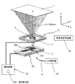
- FIG. 1 is a perspective view showing a schematic configuration of an image sensor position adjusting apparatus according to a first embodiment of the present invention.
- FIG. 2 is a schematic cross-sectional view showing the configuration of the lens unit and the imaging unit of the image sensor position adjusting device.
- FIG. 3 is a plan view of a measurement chart of the position adjusting device for the image sensor.
- FIG. 4 is a diagram showing the relationship between the subject distance and the focal position movement amount.
- FIG. 5 is a diagram illustrating the relationship between the gap between the photographic lens and the image sensor and the allowable rotation angle of the image sensor.
- FIG. 6 is a diagram for explaining the relationship of the focal position with respect to the subject distance of the lens unit and the imaging unit.
- FIG. 7 is a diagram for explaining the tilt adjustment of the imaging unit.
- FIG. 1 is a perspective view showing a schematic configuration of an image sensor position adjusting apparatus according to a first embodiment of the present invention.
- FIG. 2 is a schematic cross-sectional view showing the configuration of the
- FIG. 8 is a diagram showing the correlation between the subject distance and the SFR value at an image height of 0% of the image sensor position adjusting apparatus according to the second embodiment of the present invention.
- FIG. 9 is a diagram showing the correlation between the subject distance and the SFR value at an image height of 60% of the image sensor position adjusting device.
- FIG. 10 is an enlarged view of the main part of FIG.
- FIG. 11 is an enlarged view of a main part of FIG.
- FIG. 12 is a diagram showing the correlation between the subject distance and the SFR value at an image height of 90%.
- FIG. 13 is a diagram for explaining variations in peak coordinates based on the SFR value of the peripheral image height with respect to the image center.
- FIG. 14 is a block diagram of a control device for an image sensor position adjusting device according to a third embodiment of the present invention.
- FIG. 1 is a perspective view showing a schematic configuration of an image sensor position adjusting apparatus according to a first embodiment of the present invention.
- the position of the image sensor of a camera module used for a smart phone or a digital camera is adjusted.
- the position adjustment device for the image sensor includes a measurement chart 1 and a lens positioning jig having a lens holding mechanism 11 as an example of a lens unit holding unit that holds the lens unit 2. 10 and an inclination adjustment unit 20b for adjusting the inclination of the imaging unit around the Z axis and the inclinations around the X axis and the Y axis perpendicular to the Z axis based on the chart image captured by the imaging unit 3 and the imaging unit holding
- the moving mechanism 20 including the part 20a is provided.
- the lens unit 2 is arranged on the Z axis orthogonal to the measurement chart 1.
- the image pickup unit 3 (sensor substrate) is mounted with an image pickup element 82 (shown in FIG. 2) arranged on the Z axis so as to pick up a chart image formed by the lens unit 2.
- the lens unit 2 includes a unit main body 71, a photographing lens 72 incorporated in the unit main body, and a VCM (Voice Coil Moto: voice) that moves the photographing lens 72 along the optical axis direction.
- VCM Vehicle Coil Moto: voice
- -Coil motor 73.
- the photographing lens 72 is mainly composed of, for example, 3 to 5 plastic lenses or glass lenses (in the first embodiment, 3 lenses).
- the imaging unit 3 includes a substrate 81 and an imaging element 82 mounted on the substrate 81.
- the moving mechanism 20 shown in FIG. 1 moves in the Z-axis direction, moves in the X-axis direction perpendicular to the Z-axis, moves in the Y-axis direction perpendicular to the Z-axis and the X-axis, and rotates around the Z-axis.
- a 6-axis stage having a function of rotating around the X axis and rotating around the Y axis.
- the image sensor position adjusting device applies a VCM 73 (shown in FIG. 2) of the lens unit 2 and a control device 30 that controls the moving mechanism 20 and an adhesive for fixing the imaging unit 3 to the lens unit 2.
- An adhesive application device 40 as an example of a filling unit that performs this process and a UV irradiator 50 that irradiates ultraviolet rays to harden the adhesive are provided.
- the control device 30 uses the SFR (spatial frequency response) to image the image pickup surface of the image pickup device 82 with respect to the image formation surface of the chart image formed by the photographing lens 72.
- An inclination calculating unit 30a that calculates inclinations around the X, Y, and Z axes is provided.
- the control device 30 may be a personal computer or may be composed of a microcomputer and an input / output circuit.
- the image sensor position adjustment device having the above-described configuration is disposed on, for example, a vibration isolation table.
- the specifications of the imaging unit of the camera module that is adjusted using the imaging device position adjusting device of this embodiment are as follows. Number of pixels: 8 million pixels Image sensor: CMOS sensor Focal length: 4.2 mm
- the measurement chart 1 has a light source (reflection type or transmission type) for chart illumination.
- the moving mechanism 20 (shown in FIG. 1) is disposed at the lower part of the suction unit holding portion 20a including a suction pad (not shown) that sucks the imaging unit 3 (sensor substrate), and is provided on the control device. And a six-axis stage (not shown) including an inclination adjusting unit 20b controlled by 30 (shown in FIG. 1).
- the upper surface of a suction pad (not shown) that sucks the lens unit 2 is used as a reference surface, and the distance L from the reference surface to the measurement chart 1 is 600 mm.
- An air pump (not shown) is connected to the suction pad (not shown) of the lens holding mechanism 11 and the suction pad (not shown) of the moving mechanism 20.
- the suction force of the air pump attracts and positions the lens unit 2 on the suction pad of the lens holding mechanism 11 and positions the imaging unit 3 on the suction pad of the moving mechanism 20.
- FIG. 3 is a plan view of the measurement chart 1 of the position adjusting device for the image sensor.
- the measurement chart 1 is divided into first to fourth quadrants by a perpendicular and a horizontal line passing through the center of the rectangular chart surface.
- Black square chart patterns 61 and 61 are printed on the first and second quadrants of the chart surface of the measurement chart 1.
- black square chart patterns 62 and 62 are printed on the third and fourth quadrants of the chart surface of the measurement chart 1, and a chart pattern 63 is printed at the center of the chart surface.
- FIG. 4 shows the relationship between the subject distance L and the amount of movement of the focal position movement amount D (the amount of deviation between the imaging surface and the imaging surface of the image sensor 82) in the camera module composed of the lens unit 2 and the imaging unit 3. Yes.
- the camera module set so that an image of an object at infinity is focused on the imaging surface of the imaging unit 3 by the lens unit 2, for the measurement chart 1 arranged at a position of 600 mm, By extending the photographic lens 72 to the subject side by 0.029 mm, the chart image of the measurement chart 1 is focused on the imaging surface of the imaging device 82 (the focusing surface is shifted).
- the margin for adjusting the tilt of the imaging unit 3 is widened with respect to the rotation angle of the imaging unit 3 (sensor substrate) obtained by the focus evaluation value analysis. Then, as shown in FIG. 7, after adjusting the tilt of the imaging unit 3, the lens unit 2 is lowered by 0.029 mm with respect to the Z-axis direction (an infinity lens design position), and the lens unit 2 and the imaging unit 3 are moved. Adhere with an adhesive.
- Sensor adjustment ( ⁇ x, ⁇ y) of .5 ° ⁇ 60) is possible.
- the chart image formed by the photographing lens 72 of the lens unit 2 is picked up by the image pickup element 82 of the image pickup unit 3 while moving the image pickup unit 3 in the Z-axis direction,
- the focus evaluation value of each chart pattern of the chart image is acquired using the set evaluation area.
- An approximate imaging plane is calculated by developing the focusing evaluation value of each chart pattern obtained for each evaluation area in a three-dimensional coordinate system, and imaging is performed so that the imaging plane matches the approximate imaging plane. Adjust the tilt of unit 3.
- UV + heat combination adhesive is applied to a predetermined area on the substrate 81 on which the image pickup element 82 of the image pickup unit 3 is mounted, thereby adjusting the tilt of the image pickup unit 3.
- ultraviolet rays are irradiated from the UV irradiator 50 through the optical fiber 51.
- the adhesive is temporarily cured so that the relative positional relationship between the lens unit 2 and the imaging unit 3 can be maintained, and then the adhesive is fully cured in a high temperature furnace.
- the UV + heat combination type adhesive is used.
- the present invention is not limited to this, and an instantaneous adhesive, a thermosetting adhesive, a natural curing adhesive, or the like may be used.
- the gap between the lens unit 2 and the imaging unit 3 is not filled with an adhesive, but is applied in advance before adjusting the angle of the imaging unit 3.
- the position adjustment apparatus increases in the height direction but also increases in the width direction and the depth direction. Further, regarding the production cost of the measurement chart, it is difficult to print on one large sheet at a time, and one large plate material that does not bend is required, so that the cost is greatly increased.
- the rotation system around the X axis and the Y axis of the image pickup unit 3 is an automatic biaxial goniometer stage, and the rotation of the two motors makes the image pickup unit 3 around the X axis around the center of the image pickup surface.
- the imaging unit 3 is tilted in the ⁇ X direction and the ⁇ Y direction around the Y axis orthogonal to the Z axis and the X axis. Thereby, when the imaging unit 3 is tilted in each direction, the positional relationship between the center of the imaging surface and the Z axis is prevented from being shifted.
- the focus evaluation value analysis is performed using a spatial frequency response (Spatial Frequency Response).
- the focus evaluation value analysis may use other evaluation values such as an MTF (Modulation Transfer Function) value.
- MTF Modulation Transfer Function
- the outer shape of the board on which is mounted is ⁇ 8.3 mm
- there is a margin of ⁇ 24 ′ ( ⁇ 0.4 ° ⁇ 60).
- the maximum rotation angle of the image pickup unit 3 is assumed to be ⁇ 20 ′ ( ⁇ ⁇ 0.33 ° ⁇ 60), and the (design value + 0.029 mm) between the photographing lens 72 and the image pickup device 82 is assumed. ) Is provided with a sufficient gap for adjusting the inclination of the imaging unit 3.
- the image sensor position adjusting apparatus of the first embodiment by arranging the measurement chart 1 at a short distance (600 mm) with respect to the photographing lens 72, not only in the optical axis direction but also in the width direction and the depth direction.
- the position adjusting device main body can be reduced in size, and the manufacturing cost of the measurement chart 1 can be reduced.
- the imaging lens 72 is also connected to the imaging lens 72 with respect to the imaging lens 72 having a large adjustment angle of the imaging unit 3. 82 becomes difficult to interfere, the absolute number of camera modules that can be adjusted in the mass production process can be increased, the number of defective products is reduced, and the yield is improved, so that the manufacturing cost can be reduced.
- the photographic lens 72 is moved to the subject side with respect to the position of the photographic lens 72 that forms an image of the subject at a position corresponding to infinity on the imaging surface of the imaging element 82, and the photographic lens 72 and the imaging element 82 are moved.
- the inclination of the image sensor 82 can be adjusted by widening the distance between the image sensor 82 and the margin for adjusting the tilt can be sufficiently secured even if the adjustment angle of the image sensor 82 and the photographing lens 72 by the active alignment is large.
- the image sensor 82 may be moved to the side opposite to the subject.
- the imaging unit 3 in which the gap between the lens unit 2 and the lens unit 2 varies after the inclination is adjusted by filling an adhesive into the gap between the lens unit 2 and the imaging unit 3 by the adhesive application device 40 (filling unit). can be easily fixed to the lens unit 2.
- At least one of an ultraviolet curable adhesive or a thermosetting adhesive is bonded to at least a part of the gap between the lens unit 2 and the imaging unit 3.
- the adhesive between the lens unit 2 and the image pickup unit 3 can be easily filled in the state before adjusting the inclination of the image pickup element 82, and the lens unit 2 and the image pickup after the inclination adjustment. Even if there is a portion where the distance from the unit 3 is narrow, the lens unit 2 and the imaging unit 3 can be securely and easily bonded by irradiating the heated adhesive with ultraviolet rays or heating the adhesive.
- the X axis of the image pickup surface of the image pickup device 82 with respect to the image formation surface of the chart image formed by the photographing lens 72 using SFR (spatial frequency response) Since the inclination calculation unit 30a calculates the inclination about the Y-axis and the Z-axis, the focus evaluation can be performed with high accuracy even from a blurred image by SFR (spatial frequency response), and the result of the chart image formed by the photographing lens 72 can be obtained.
- the inclination about the X axis, Y axis, and Z axis of the image pickup surface of the image pickup element 82 with respect to the image plane can be accurately calculated.
- the image sensor position adjusting apparatus of the second embodiment has the same configuration as the image sensor position adjusting apparatus of the first embodiment except for the subject distance.
- FIG. 8 shows the correlation between the subject distance and the SFR value at an image height of 0% of the image sensor position adjustment device of the second embodiment of the present invention
- FIG. 9 shows the subject at an image height of 60% of the image sensor position adjustment device. It is a figure which shows the correlation of distance and a SFR value.
- the SFR value representing the resolution is higher as the distance of the subject (measurement chart 1) is longer, and the peripheral image height near the center of the image is SFR relative to the distance of the subject (measurement chart 1). The value becomes higher.
- FIGS. 10 and 11 show an enlarged view of the main part of FIG. 8, and FIG. 11 shows an enlarged view of the main part of FIG.
- the equivalent performance is exhibited at the object distance of 100 mm or more at the image height of 0%, and the image height of 0%. With a subject distance of 200 mm or more, the same performance is exhibited.
- FIG. 12 showing the correlation between the subject distance and the SFR value at an image height of 90%, the equivalent performance is exhibited at an image height of 90% and an object distance of 200 mm or more.
- Table 1 shows the numerical data in FIG. 10
- Table 2 shows the numerical data in FIG. 11
- Table 3 shows the numerical data in FIG. 12 (in Tables 1 to 3, “Inf” represents infinity). .
- FIG. 13 shows a diagram for explaining the variation of the peak coordinates based on the SFR value of the peripheral image height with respect to the image center.
- the horizontal axis represents the Z-axis coordinate [mm]
- the vertical axis represents the SFR value.
- the black diamond ( ⁇ ) indicates the SFR value of 0% image height (“IH0.0”)
- the black square ( ⁇ ) indicates the first image height 60% (“IH0.6 ⁇
- the SFR value of 1 ”) and the black triangle (() are the SFR value of the second image height of 60% (“ IH0.0-2 ”).
- the SFR value at each image height is preferably equivalent to the SFR value of the object at infinity, and the SFR value deterioration is 3% or less with respect to the SFR value of the object at infinity as a numerical range that does not have a large difference. Up to the characteristic guarantee area.
- the position adjustment device for the image sensor can be reduced in size and cost, and the adjustment accuracy can be improved.
- the resolution of the same image height decreases as the subject distance decreases.
- Tables 1 to 3 assuming that the subject resolution of an infinite subject is 1, the subject distance at which the resolution is degraded by 3% is 100 mm at an image height of 0%, 200 mm at an image height of 60%, and the image height. 90% is 200 mm.
- the subject distance of the closest image is 200 mm.
- the subject distance of the closest image is 600 mm as an area where resolution degradation is almost zero.
- the measurement chart 1 is arranged in an area (ideally 600 mm, 200 mm or more from the simulation result) where an SFR value equivalent to infinity is obtained.
- the position of the one closer to the photographing lens 72 is fed forward than the measurement chart is arranged at infinity.
- the focal position movement amount (the extension amount of the photographing lens 72) up to a subject distance of about 5000 mm, and a large value with an inflection point of 2000 mm. If a gap of at least 10 ⁇ m is not obtained with respect to the position of the infinitely far photographing lens 72, the gap is not secured with respect to the position of the infinitely far photographing lens 72. It is necessary to arrange within 2000 mm. From this point, the arrangement of the measurement chart 1 is set within 2000 mm from the photographing lens 72.
- the measurement chart 1 is more preferable to install the measurement chart 1 at a subject distance of 1000 mm that can effectively widen the gap between the imaging lens 72 and the imaging element 82. This not only reduces the size of the measurement chart and reduces the size of the device, but also contributes to cost reduction of the device.
- the height of the device is within a maximum of 2 to 3 m.
- the upper limit of the subject distance is set to 2000 mm, but is preferably set to 1000 mm or less.
- the apparatus body can be downsized with the adjustment angle of the photographing lens 72 within an allowable error, and the measurement system (measurement housing) Body and measurement chart) and the adjustment accuracy can be improved.
- the distance L between the measurement chart 1 and the photographic lens 72 is set as follows. 200mm ⁇ L ⁇ 2000mm further, 400mm ⁇ L ⁇ 1000mm More preferably. By setting it within the range of this condition, it is possible to easily secure the distance between the imaging lens 72 and the imaging element 82 when the position of the imaging element 82 is adjusted while reducing the size of the apparatus main body.
- FIG. 14 is a block diagram of the control device 130 of the image sensor position adjusting device according to the third embodiment of the present invention.
- the image sensor position adjusting device of the third embodiment has the same configuration as the image sensor position adjusting device of the first embodiment except for the control device, and FIGS.
- the control device 130 is based on the chart image picked up by the image pickup device 82 and uses the SFR (spatial frequency response) to image the chart image formed by the photographing lens 72.
- An inclination calculation unit 130a that calculates inclinations around the X axis, Y axis, and Z axis of the imaging surface of the image sensor 82, and a chart pattern that includes at least a part of an imaging position set in advance on the imaging surface of the image sensor 82
- a pattern evaluation unit 130b for recognizing an image and a focus evaluation value calculated using an evaluation region for each chart pattern of a chart image determined with reference to the position of the chart pattern recognized by the chart pattern recognition unit 130b.
- a focus evaluation value calculation unit 130c is based on the chart image picked up by the image pickup device 82 and uses the SFR (spatial frequency response) to image the chart image formed by the photographing lens 72.
- An inclination calculation unit 130a that calculates inclinations around the X axis, Y axis,
- the relationship between the image pickup surface of the image pickup device 82 of the image pickup unit 3 and the image formation surface of the chart pattern changes due to a change in magnification.
- the edge of the left side of the rectangular chart pattern is detected by image processing (pattern matching), and processing for analyzing a predetermined area from that point according to each image height is performed. ing.
- the apparatus can be stably operated and the adjustment accuracy can be improved.
- the focus evaluation value calculation unit 130c can calculate the focus evaluation value without any problem.
- the image sensor position adjustment apparatus including the measurement chart 1 in which a plurality of black square chart patterns 61 and 62 are printed on the chart surface has been described.
- the chart pattern is not limited to this, and may be a ladder-like chart pattern in which straight lines are arranged at a predetermined interval.
- a 6-axis stage having a function of rotating around the Y axis is used as the moving mechanism 20
- the inclination of the image pickup element held by the image pickup unit holding unit around the Z axis is within an allowable range.
- the moving mechanism may not have a function of rotating around the Z axis.
- Patent Document 2 Japanese Patent Laid-Open No. 2006-30256
- a mechanism for exchanging the measurement chart is required (if the measurement chart is fixed, a moving mechanism is required).
- the operation accuracy of the mechanism is required when changing the measurement chart (positioning accuracy).
- the image sensor position adjustment apparatus of the present invention uses the same subject (measurement chart) for the focus and image sensor adjustment angle, both of which are adjusted with resolution. Since this resolution is almost correlated with the blur of the actual photograph, a result close to the image seen by human eyes is obtained, and has the following features (a) to (d). (a) Just adjust during assembly. (b) There is no need to change the measurement chart. (c) The cost for one measurement chart is sufficient. (d) Space for one measurement chart is sufficient.
- An image sensor position adjusting device includes: A measurement chart 1 in which a plurality of chart patterns are formed; A lens unit holding unit 11 for holding the lens unit 2 in which the taking lens 72 arranged on the Z axis orthogonal to the measurement chart 1 is incorporated; An imaging unit holding unit 20a for holding the imaging unit 3 in which the imaging element 82 arranged on the Z-axis is incorporated so as to capture the chart image of the measurement chart 1 formed by the imaging lens 72; , A moving mechanism 20 that moves either the lens unit holding unit 11 or the imaging unit holding unit 20a along the Z-axis direction; Based on the chart image of the measurement chart imaged by the imaging element 82 while moving either the lens unit holding unit 11 or the imaging unit holding unit 20a along the Z-axis direction by the moving mechanism 20.
- a tilt adjusting unit 20b that adjusts the tilt around the Z-axis of the image sensor 82 and the tilt around the X-axis and the Y-axis intersecting the Z-axis,
- the distance L between the measurement chart 1 and the photographic lens 72 is 200mm ⁇ L ⁇ 2000mm It satisfies the following conditions.
- the measurement chart 1 can be disposed at a short distance from the photographing lens 72, and the apparatus main body can be downsized not only in the optical axis direction but also in the width direction and the depth direction.
- the photographic lens 72 is moved to the subject side with respect to the position of the photographic lens 72 that forms an image of the subject at a position corresponding to infinity on the imaging surface of the imaging device 82, or the imaging device 82 is moved to the subject.
- the image sensor 82 can be tilted by widening the distance between the photographic lens 72 and the image sensor 82, and the adjustment angle of the image sensor 82 and the photographic lens 72 by active alignment is large. However, a sufficient margin for tilt adjustment can be ensured by a low-cost and space-saving image sensor position adjusting device.
- the distance L between the measurement chart 1 and the photographic lens 72 is 400mm ⁇ L ⁇ 1000mm Satisfy the condition of
- a filling portion 40 for filling an adhesive into at least a part of the gap between the lens unit 2 and the imaging unit 3 is provided.
- the imaging unit 3 in which the gap between the lens unit 2 and the lens unit 2 varies after the tilt adjustment is obtained. It can be easily fixed to the unit 2.
- the filling unit 40 is configured such that an ultraviolet curable adhesive or thermosetting is applied to at least a part of the gap before adjusting the angles around the X, Y, and Z axes of the image sensor 82 by the tilt adjusting unit 20b. Fill at least one of the mold adhesives.
- At least a part of the gap between the lens unit 2 and the imaging unit 3 is filled with at least one of an ultraviolet curable adhesive or a thermosetting adhesive before adjustment by the inclination adjusting unit 20b.
- the adhesive between the lens unit 2 and the imaging unit 3 can be easily filled before the inclination of the imaging element 82 is adjusted, and the lens unit 2 and the imaging unit 3 are adjusted after the inclination adjustment. Even if there is a portion where the distance between the lens unit 2 and the imaging unit 3 is narrowed, the lens unit 2 and the imaging unit 3 can be reliably and easily bonded to each other by irradiating or heating the filled adhesive with ultraviolet rays.
- the image sensor position adjustment device Based on the chart image picked up by the image pickup element 82, X of the image pickup surface of the image pickup element 82 with respect to the image formation surface of the chart image formed by the photographing lens 72 using SFR (spatial frequency response).
- An inclination calculating unit 130a for calculating inclinations about the axis, the Y axis, and the Z axis;
- the tilt adjusting unit 20b is configured to determine the X axis, Y axis, and Y axis of the image sensor 82 based on the tilts around the X axis, Y axis, and Z axis of the imaging surface of the image sensor 82 calculated by the tilt calculator 130a. Adjust the tilt around the Z axis.
- SFR spatial frequency response
Landscapes
- Engineering & Computer Science (AREA)
- Physics & Mathematics (AREA)
- Health & Medical Sciences (AREA)
- Biomedical Technology (AREA)
- General Health & Medical Sciences (AREA)
- Multimedia (AREA)
- Signal Processing (AREA)
- General Physics & Mathematics (AREA)
- Optics & Photonics (AREA)
- Studio Devices (AREA)
- Lens Barrels (AREA)
- Mounting And Adjusting Of Optical Elements (AREA)
Abstract
移動機構(20)によりレンズユニット保持部(11)または撮像ユニット保持部のいずれか一方をZ軸方向に沿って移動させながら撮像素子により撮像された測定チャート(1)のチャート像に基づいて、撮像素子のZ軸回りの傾きおよびそのZ軸に交わるX軸,Y軸回りの傾きを調整する傾き調整部(20b)を備える。上記測定チャート(1)と撮影レンズ(72)との距離Lが、 200mm ≦ L ≦ 2000mm の条件を満たす。これにより、撮影レンズと撮像素子との間隔を広げる簡単な構成により、撮像素子の傾き調整のマージンを十分に確保することができる低コストかつ省スペースな撮像素子の位置調整装置を提供する。
Description
この発明は、撮像素子の位置調整装置に関し、詳しくは撮影レンズに対する撮像素子の傾きを調整する撮像素子の位置調整装置に関する。
従来の第1の撮像素子の位置調整装置としては、レンズ保持機構にレンズユニットを保持させると共に、素子移動機構に撮像素子が組み込まれた撮像ユニットを保持させ、スライドステージで撮像ユニットをZ軸方向に移動させながら、撮影レンズにより結像したチャート像を撮像素子で撮像し、撮像面上に設定された少なくとも5つの撮像位置の合焦座標値を取得するものがある(例えば、特開2010-21985号公報(特許文献1)参照)。この従来の第1の撮像素子の位置調整装置は、撮像位置毎に得られた合焦座標値を3次元座標系に展開することにより得られる複数の評価点の相対位置から近似結像面を算出して、この近似結像面に撮像面が一致するように、第2スライドステージおよび2軸回転ステージで撮像ユニットの位置および傾きを調整する。
また、従来の第2の撮像素子の位置調整装置としては、2枚の試験チャートを用いて撮像素子の位置と角度の調整を行うものがある(例えば、特開2006-30256号公報(特許文献2)参照)。この従来の第2の撮像素子の位置調整装置では、まず白黒パターンを設けた第1の試験チャートで合焦評価を行い(フォーカス)、白色のチャートである第2の試験チャートで周辺光量比を測定して、撮像素子の調整角度(センサチルト量)を求める。上記従来の第2の撮像素子の位置調整装置では、周辺光量比は、解像度と100%の相関関係があるとは言えず、また、周辺光量比は、光源(被写体照明用)とレンズの特性の積で決まる値であり、光源の照度分布にも影響されるため、照度分布にばらつきのない均一発光光源を用いれば、照度分布の影響を小さくすることができるが、コストが高くなる。また、上記撮像素子の位置調整装置において、照度分布にばらつきのある不均一発光光源を用いれば、低コストにできるが、撮像素子の傾きの計算結果にばらつきが生じてしまう。
しかしながら、上記従来の第1,第2の撮像素子の位置調整装置では、特にレンズユニットの撮影レンズと撮像ユニットの撮像素子との間のギャップが狭いカメラモジュールにおいて、撮像素子の調整角度が大きい場合に傾き調整のマージンを十分に確保することでできないという問題がある。
そこで、この発明の課題は、撮影レンズと撮像素子との間隔を広げる簡単な構成により、撮像素子の傾き調整のマージンを十分に確保することができる低コストかつ省スペースな撮像素子の位置調整装置を提供することにある。
上記課題を解決するため、この発明の撮像素子の位置調整装置は、
複数のチャートパターンが形成された測定チャートと、
上記測定チャートに直交するZ軸上に配置された撮影レンズが組み込まれたレンズユニットを保持するためのレンズユニット保持部と、
上記撮影レンズによって結像される上記測定チャートのチャート像を撮像するように上記Z軸上に配置された撮像素子が組み込まれた撮像ユニットを保持するための撮像ユニット保持部と、
上記レンズユニット保持部または上記撮像ユニット保持部のいずれか一方を、上記Z軸方向に沿って移動させる移動機構と、
上記移動機構により上記レンズユニット保持部または上記撮像ユニット保持部のいずれか一方を上記Z軸方向に沿って移動させながら上記撮像素子により撮像された上記測定チャートのチャート像に基づいて、上記撮像素子のZ軸回りの傾きおよびそのZ軸に直交するX軸,Y軸回りの傾きを調整する傾き調整部と
を備え、
上記測定チャートと上記撮影レンズとの距離Lは、
200mm ≦ L ≦ 2000mm
の条件を満たすことを特徴とする。
なお、この発明の撮像素子の位置調整装置は、レンズユニットおよび撮像ユニットを含まない。
複数のチャートパターンが形成された測定チャートと、
上記測定チャートに直交するZ軸上に配置された撮影レンズが組み込まれたレンズユニットを保持するためのレンズユニット保持部と、
上記撮影レンズによって結像される上記測定チャートのチャート像を撮像するように上記Z軸上に配置された撮像素子が組み込まれた撮像ユニットを保持するための撮像ユニット保持部と、
上記レンズユニット保持部または上記撮像ユニット保持部のいずれか一方を、上記Z軸方向に沿って移動させる移動機構と、
上記移動機構により上記レンズユニット保持部または上記撮像ユニット保持部のいずれか一方を上記Z軸方向に沿って移動させながら上記撮像素子により撮像された上記測定チャートのチャート像に基づいて、上記撮像素子のZ軸回りの傾きおよびそのZ軸に直交するX軸,Y軸回りの傾きを調整する傾き調整部と
を備え、
上記測定チャートと上記撮影レンズとの距離Lは、
200mm ≦ L ≦ 2000mm
の条件を満たすことを特徴とする。
なお、この発明の撮像素子の位置調整装置は、レンズユニットおよび撮像ユニットを含まない。
また、一実施形態の撮像素子の位置調整装置では、
上記測定チャートと上記撮影レンズとの距離Lは、
400mm ≦ L ≦ 1000mm
の条件を満たす。
上記測定チャートと上記撮影レンズとの距離Lは、
400mm ≦ L ≦ 1000mm
の条件を満たす。
また、一実施形態の撮像素子の位置調整装置では、
上記レンズユニットと上記撮像ユニットとの間に有する空隙の少なくとも一部に接着剤を充填する充填部を備えた。
上記レンズユニットと上記撮像ユニットとの間に有する空隙の少なくとも一部に接着剤を充填する充填部を備えた。
また、一実施形態の撮像素子の位置調整装置では、
上記充填部は、上記撮像素子のX軸,Y軸およびZ軸回りの角度を上記傾き調整部により調整する前に、上記空隙の少なくとも一部に紫外線硬化型の接着剤または熱硬化型の接着剤の少なくとも一方を充填する。
上記充填部は、上記撮像素子のX軸,Y軸およびZ軸回りの角度を上記傾き調整部により調整する前に、上記空隙の少なくとも一部に紫外線硬化型の接着剤または熱硬化型の接着剤の少なくとも一方を充填する。
上記実施形態によれば、傾き調整部による調整する前に、レンズユニットと撮像ユニットとの空隙の少なくとも一部に紫外線硬化型の接着剤または熱硬化型の接着剤の少なくとも一方を充填部により充填することによって、撮像素子の傾きを調整する前の状態でレンズユニットと撮像ユニットとの間隔に接着剤を容易に充填できると共に、傾き調整後にレンズユニットと撮像ユニットとの間隔が狭くなった箇所があっても、充填された接着剤に対して紫外線を照射するかまたは加熱することにより、レンズユニットと撮像ユニットとを確実かつ容易に接着できる。
また、一実施形態の撮像素子の位置調整装置では、
上記撮像素子により撮像された上記チャート像に基づいて、SFR(空間周波数応答)を用いて上記撮影レンズにより結像された上記チャート像の結像面に対する上記撮像素子の撮像面のX軸,Y軸,Z軸回りの傾きを算出する傾き算出部を備え、
上記傾き調整部は、上記傾き算出部により算出された上記撮像素子の撮像面のX軸,Y軸,Z軸回りの傾きに基づいて、上記撮像素子のX軸,Y軸,Z軸回りの傾きを調整する。
上記撮像素子により撮像された上記チャート像に基づいて、SFR(空間周波数応答)を用いて上記撮影レンズにより結像された上記チャート像の結像面に対する上記撮像素子の撮像面のX軸,Y軸,Z軸回りの傾きを算出する傾き算出部を備え、
上記傾き調整部は、上記傾き算出部により算出された上記撮像素子の撮像面のX軸,Y軸,Z軸回りの傾きに基づいて、上記撮像素子のX軸,Y軸,Z軸回りの傾きを調整する。
上記実施形態によれば、撮像素子により撮像されたチャート像に基づいて、SFR(空間周波数応答)を用いて撮影レンズにより結像されたチャート像の結像面に対する撮像素子の撮像面のX軸,Y軸,Z軸回りの傾きを傾き算出部により算出するので、SFR(空間周波数応答)により不鮮明な画像からでも精度よく合焦評価ができ、撮影レンズにより結像されたチャート像の結像面に対する撮像素子の撮像面のX軸,Y軸,Z軸回りの傾きを正確に算出することができる。
以上より明らかなように、この発明によれば、撮影レンズと撮像素子との間隔を広げることにより、撮影レンズと撮像素子との間隔を広げる簡単な構成により、撮像素子の傾き調整のマージンを十分に確保することができる低コストかつ省スペースな撮像素子の位置調整装置を実現することができる。
また、撮影レンズに対して測定チャートを近距離に配置することで、光軸方向だけでなく、幅方向・奥行き方向に対しても装置本体を小型化できる。
また、望遠端近くに配置した測定チャートよりも小さい測定チャートで撮像素子の位置調整が可能となり、材料費・加工費などの製造コストを削減できる。
また、撮像素子の位置調整時の撮影レンズと撮像素子との間隔を確保することにより、調整角度が大きな撮影レンズに対しても撮像素子を撮影レンズが干渉しにくくなり、量産工程において調整可能なカメラモジュールの絶対数を増やすことができる。
このようにして、調整可能なカメラモジュールが増えることによって、不良品数が減って歩留まりが向上するため、製造コストを低減することができる。
以下、この発明の撮像素子の位置調整装置を図示の実施の形態により詳細に説明する。
〔第1実施形態〕
図1はこの発明の第1実施形態の撮像素子の位置調整装置の概略構成を示す斜視図である。なお、この第1実施形態では、スマートホンやデジタルカメラなどに用いられるカメラモジュールの撮像素子の位置調整を行う。
図1はこの発明の第1実施形態の撮像素子の位置調整装置の概略構成を示す斜視図である。なお、この第1実施形態では、スマートホンやデジタルカメラなどに用いられるカメラモジュールの撮像素子の位置調整を行う。
この第1実施形態の撮像素子の位置調整装置は、図1に示すように、測定チャート1と、レンズユニット2を保持するレンズユニット保持部の一例としてのレンズ保持機構11を有するレンズ位置決め治具10と、撮像ユニット3により撮像されたチャート像に基づいて、撮像ユニットのZ軸回りの傾きおよびそのZ軸に直交するX軸,Y軸回りの傾きを調整する傾き調整部20bと撮像ユニット保持部20aを含む移動機構20を備えている。
上記レンズユニット2は、測定チャート1に直交するZ軸上に配置されている。また、上記撮像ユニット3(センサ基板)は、レンズユニット2によって結像されるチャート像を撮像するようにZ軸上に配置された撮像素子82(図2に示す)が搭載されている。
上記レンズユニット2は、図2に示すように、ユニット本体71と、ユニット本体内に組み込まれた撮影レンズ72と、その撮影レンズ72を光軸方向に沿って移動させるVCM(Voice Coil Moto:ボイス・コイル・モータ)73とを有する。上記撮影レンズ72は、例えば3~5枚のプラスチックレンズまたはガラスレンズで主に構成されている(この第1実施形態では3枚構成)。
また、上記撮像ユニット3は、図2に示すように、基板81と、その基板81上に搭載された撮像素子82とを有する。
また、図1に示す移動機構20は、Z軸方向の移動と、Z軸に直交するX軸方向の移動と、Z軸かつX軸に直交するY軸方向の移動と、Z軸回りの回転と、X軸回りの回転と、Y軸回りの回転を行う機能を備えた6軸ステージである。
また、上記撮像素子の位置調整装置は、レンズユニット2のVCM73(図2に示す)や移動機構20を制御する制御装置30と、レンズユニット2に撮像ユニット3を固定するための接着剤を塗布する充填部の一例としての接着剤塗布装置40と、接着剤を固めるための紫外線を照射するUV照射機50とを備えている。
上記制御装置30は、撮像素子82により撮像されたチャート像に基づいて、SFR(空間周波数応答)を用いて撮影レンズ72により結像されたチャート像の結像面に対する撮像素子82の撮像面のX軸,Y軸,Z軸回りの傾きを算出する傾き算出部30aを有する。なお、制御装置30には、パーソナルコンピュータを用いてもよいし、マイクロコンピュータと入出力回路などからなるものでよい。
上記構成の撮像素子の位置調整装置は、例えば除振台等の上に配置される。
なお、この実施の形態の撮像素子の位置調整装置を用いて調整するカメラモジュールの撮像ユニットの仕様は次の通りである。
画素数:800万画素
撮像素子:CMOSセンサ
焦点距離:4.2mm
画素数:800万画素
撮像素子:CMOSセンサ
焦点距離:4.2mm
また、測定チャート1は、チャート照明用の光源(反射型または透過型)を有する。
また、移動機構20(図1に示す)は、撮像ユニット3(センサ基板)を吸着する吸着パッド(図示せず)を含む撮像ユニット保持部20aと、その吸着パッドの下部に配置され、制御装置30(図1に示す)により制御される傾き調整部20bを含む6軸ステージ(図示せず)を有する。
図1において、レンズユニット2を吸着する吸着パッド(図示せず)の上面を基準面とし、その基準面から測定チャート1までの距離Lを600mmとしている。
上記レンズ保持機構11の吸着パッド(図示せず)および移動機構20の吸着パッド(図示せず)にエアポンプ(図示せず)を接続している。このエアポンプの吸引力によって、レンズ保持機構11の吸着パッドにレンズユニット2が吸着して位置決めされると共に、移動機構20の吸着パッドに撮像ユニット3が吸着して位置決めされる。
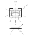
また、図3は上記撮像素子の位置調整装置の測定チャート1の平面図を示している。この測定チャート1は、図3に示すように、矩形状のチャート面の中心を通る垂線と水平線で第1~第4象限に4分割されている。測定チャート1のチャート面の第1,第2象限上に、黒色の正方形状のチャートパターン61,61を印刷している。また、測定チャート1のチャート面の第3,第4象限上に、黒色の正方形状のチャートパターン62,62を印刷すると共に、チャート面の中央部分にチャートパターン63を印刷している。
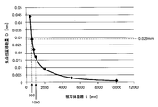
図4は上記レンズユニット2と撮像ユニット3で構成されたカメラモジュールにおいて被写体距離Lと焦点位置移動量Dの繰出量(撮像素子82の撮像面と結像面のずれ量)の関係を示している。上記レンズユニット2により無限遠の被写体の像が撮像ユニット3の撮像面に結像して合焦するように設定されたカメラモジュールにおいて、600mmの位置に配置された測定チャート1に対しては、撮影レンズ72を被写体側に0.029mm繰り出すことにより、測定チャート1のチャート像が撮像素子82の撮像面に結像して合焦する(合焦面がずれる)。
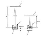
従って、レンズユニット2を測定チャート1の方向に持ち上げるか、または、図6に示すように、撮像ユニット3(センサ基板)を測定チャート1とは逆方向(撮像素子82側)に下げることで、これまでのプロセス(レンズユニットと撮像ユニットを機械的に当接させて接着)よりも、撮影レンズ72と撮像素子82との間のギャップを0.029mm増やすことができるため、撮像素子82の傾き調整に使用できる空間が広がる。
このため、合焦評価値解析によって求められた撮像ユニット3(センサ基板)の回転角度に対して、撮像ユニット3の傾き調整のマージンが広がる。そして、図7に示すように、撮像ユニット3の傾き調整後に、レンズユニット2をZ軸方向に対して0.029mm下げて(無限遠のレンズ設計位置)、レンズユニット2と撮像ユニット3とを接着剤により接着する。
例えば、撮影レンズ72との距離が600mmの測定チャート1で合焦評価値の解析には、撮像ユニット3をZ軸方向に60μm~100μmのストロークを確保することで、±30′(=±0.5°×60)のセンサ調整(θx,θy)が可能となる。
合焦評価値の解析は、撮像ユニット3をZ軸方向に移動させながら、レンズユニット2の撮影レンズ72により結像したチャート像を撮像ユニット3の撮像素子82で撮像して、撮像面上に設定された評価領域を用いてチャート像の各チャートパターンの合焦評価値を取得する。この評価領域毎に得られた各チャートパターンの合焦評価値を3次元座標系に展開することにより近似結像面を算出して、この近似結像面に撮像面が一致するように、撮像ユニット3の傾きを調整する。
上記撮像ユニット3の傾き調整前に、撮像ユニット3の撮像素子82が搭載された基板81上の予め定められた領域にUV+熱併用型の接着剤を塗布して、撮像ユニット3の傾き調整をした後に、UV照射機50から光ファイバー51を介して紫外線を照射する。これによって、レンズユニット2と撮像ユニット3との相対位置関係が保持できるように接着剤を仮硬化させ、その後、高温炉にて接着剤を本硬化させる。なお、この実施の形態では、UV+熱併用型の接着剤を用いたが、これに限らず、瞬間接着剤、熱硬化接着剤、自然硬化接着剤等を利用してもよい。
この実施形態では、撮像ユニット3の角度調整後に、レンズユニット2と撮像ユニット3との間のギャップに接着剤を充填するのでなく、撮像ユニット3の角度調整前に予め塗布しておく。
被写体距離(測定チャート1と撮像ユニット3との距離)を遠ざけると、位置調整装置全体が高さ方向に大きくなるだけでなく、幅方向・奥行き方向にも大きくなる。また、測定チャートの作製費用に関しても、1枚の大きなシートに一度に印刷するのが困難であると共に、撓まない1枚の大きな板材が必要となるため、コストが大幅にアップする。
撮像ユニット3のX軸の回りおよびY軸の回りの回転系は、自動2軸ゴニオステージで、2つのモータの回転により撮像面の中心を回転中心にして、撮像ユニット3をX軸の回りのθX方向と、Z軸およびX軸に直交するY軸の回りのθY方向で撮像ユニット3を傾ける。これにより、撮像ユニット3を各方向に傾けたときに、撮像面の中心とZ軸との位置関係がずれないようにしている。
上記実施の形態では、合焦評価値解析は、空間周波数応答(Spatial Frequency Response)を用いて行う。なお、合焦評価値解析は、MTF(Modulation Transfer Function)値などの他の評価値を用いてもよい。例えば、レンズユニット2と撮像ユニット3で構成されたカメラモジュールの完成品の撮像テストにおいて同様の項目の検査が実施されているため、チャートパターンのコントラスト比を計算して、合焦評価を行っても良い。
撮影レンズ72と撮像素子82との間のギャップを設計値(バックフォーカス)から0.029mm広げた場合の撮像ユニット3の調整角度について、例えば、レンズユニット2の外形および撮像ユニット3の撮像素子82が搭載された基板の外形を夫々□8.3mmとすると、±24′(=±0.4°×60)のマージンがあることになる。この実施形態では、撮像ユニット3の最大回転角度は、±20′(≒±0.33°×60)を想定しており、撮影レンズ72と撮像素子82との間に(設計値+0.029mm)のギャップを設けたことによって、撮像ユニット3の傾き調整に十分な隙間を有していることになる。
上記撮像ユニット3の外形を□8.3mmとするとき、撮影レンズ72と撮像素子82との間のギャップと撮像素子82の許容回転角度の関係は、図5に示すとおりである。
上記第1実施形態の撮像素子の位置調整装置によれば、測定チャート1を撮影レンズ72に対して近距離(600mm)に配置することで、光軸方向だけでなく、幅方向・奥行き方向に対しても位置調整装置本体を小型化できると共に、測定チャート1の製造コストも削減することができる。
また、撮像素子82の傾き調整において撮影レンズ72と撮像素子82との間に十分なギャップを確保することによって、撮像ユニット3の調整角度が大きい撮影レンズ72に対しても撮影レンズ72に撮像素子82が干渉しにくくなり、量産工程において調整可能なカメラモジュールの絶対数を増やすことができ、不良品数が減って歩留まりが向上するため、製造コストを下げることができる。
また、無限遠に相当する位置の被写体の像を撮像素子82の撮像面に結像させる撮影レンズ72の位置に対して、撮影レンズ72を被写体側に移動させて、撮影レンズ72と撮像素子82との間隔を広げて撮像素子82の傾き調整を行うことができ、アクティブアライメントによる撮像素子82・撮影レンズ72の調整角度が大きくても、傾き調整のマージンを十分に確保することができる。なお、撮影レンズ72を被写体側に移動させる代わりに、撮像素子82を被写体と反対の側に移動させてもよい。
また、上記レンズユニット2と撮像ユニット3との空隙の少なくとも一部に接着剤塗布装置40(充填部)により接着剤を充填することによって、傾き調整後にレンズユニット2との空隙がばらつく撮像ユニット3をレンズユニット2に容易に固定できる。
また、上記移動機構20の傾き調整部20bによる調整の前に、レンズユニット2と撮像ユニット3との空隙の少なくとも一部に紫外線硬化型の接着剤または熱硬化型の接着剤の少なくとも一方を接着剤塗布装置40により充填することによって、撮像素子82の傾きを調整する前の状態でレンズユニット2と撮像ユニット3との間隔に接着剤を容易に充填できると共に、傾き調整後にレンズユニット2と撮像ユニット3との間隔が狭くなった箇所があっても、充填された接着剤に対して紫外線を照射するかまたは加熱することにより、レンズユニット2と撮像ユニット3とを確実かつ容易に接着できる。
また、上記撮像素子82により撮像されたチャート像に基づいて、SFR(空間周波数応答)を用いて撮影レンズ72により結像されたチャート像の結像面に対する撮像素子82の撮像面のX軸,Y軸,Z軸回りの傾きを傾き算出部30aにより算出するので、SFR(空間周波数応答)により不鮮明な画像からでも精度よく合焦評価ができ、撮影レンズ72により結像されたチャート像の結像面に対する撮像素子82の撮像面のX軸,Y軸,Z軸回りの傾きを正確に算出することができる。
〔第2実施形態〕
次に、この発明の第2実施形態の撮像素子の位置調整装置について説明する。なお、この第2実施形態の撮像素子の位置調整装置は、被写体距離を除いて第1実施形態の撮像素子の位置調整装置と同一の構成をしている。
次に、この発明の第2実施形態の撮像素子の位置調整装置について説明する。なお、この第2実施形態の撮像素子の位置調整装置は、被写体距離を除いて第1実施形態の撮像素子の位置調整装置と同一の構成をしている。
図8はこの発明の第2実施形態の撮像素子の位置調整装置の像高0割における被写体距離とSFR値の相関を示し、図9は上記撮像素子の位置調整装置の像高6割における被写体距離とSFR値の相関を示す図である。
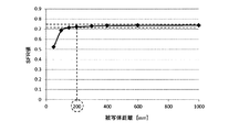
図8,図9に示すように、被写体(測定チャート1)の距離が遠いほど解像度を表すSFR値は高く、画像中心近傍の周辺像高の方が、被写体(測定チャート1)の距離に対するSFR値が高くなる。
図10は図8の要部の拡大図を示し、図11は図9の要部の拡大図を示している。図10,図11に示すように、無限遠の被写体のSFR値に対して、数値劣化を3%とすると、像高0割で被写体距離100mm以上で同等の性能を発揮し、像高0割で被写体距離200mm以上で同等の性能を発揮する。
また、像高9割における被写体距離とSFR値の相関を示す図12においても、像高9割で被写体距離200mm以上で同等の性能を発揮する。
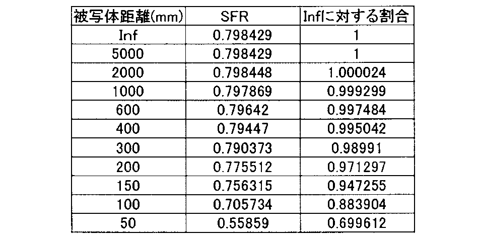
表1は図10の数値データを示し、表2は図11の数値データを示し、表3は図12の数値データを示している(表1~表3において「Inf」は無限遠を表す)。

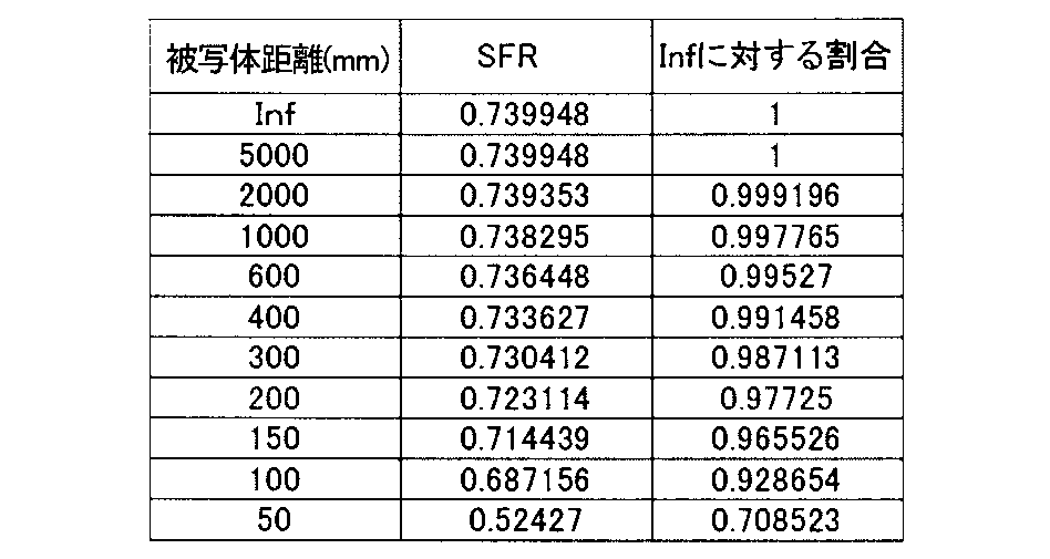
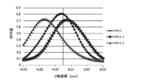
また、図13は画像中心に対する周辺像高のSFR値に基づくピーク座標のばらつきを説明するための図を示している。図13において、横軸はZ軸座標[mm]を表し、縦軸はSFR値を表している。また、図13において、黒色の菱形印(◆)は、像高0割(「IH0.0」)のSFR値、黒色の四角(■)は第1の像高6割(「IH0.6-1」)のSFR値、黒色の三角(▲)は第2の像高6割(「IH0.0-2」)のSFR値である。
図13に示すように、画像中心に対する周辺像高のSFR値に基づくピーク座標ばらつきから撮像素子82の調整角度を求めるプロセスにおいて、SFR値が小さいと、ノイズの影響が大きく、ピーク位置の再現性(ばらつき)や解析エラーの原因となり、撮像素子82の調整角度の計算結果の信頼性が下がる。従って、各像高におけるSFR値は、無限遠の被写体のSFR値相当であることが好ましく、大きな差がない数値範囲として、無限遠の被写体のSFR値に対してSFR値の劣化が3%以下までを特性保証領域とする。
無限遠の被写体のSFR値相当のSFR値が得られる領域において傾き調整を行うことによって、撮像素子の位置調整装置の小型化と低コスト化ができると共に、調整精度を向上できる。
図8~図12に示すように、被写体距離が短くなるほど同一像高の解像度が下がる。また、表1~表3に示すように、無限遠の被写体の被写体解像度を1とすると、解像度が3%劣化する被写体距離は、像高0割で100mm、像高6割で200mm、像高9割で200mmである。像高3%Lessを許容すると、最近接像の被写体距離は200mmとなる。
さらに、解像度劣化がほぼゼロの領域としては、最近接像の被写体距離は600mmとなる。
無限遠の測定チャートの配置は、現実的には困難であり、無限遠と同等のSFR値が得られる領域(理想的には600mm、シミュレーション結果からは200mm以上)に測定チャート1を配置して、合焦評価値解析を行うことにより、装置の小型化・コスト削減と調整精度を両立できる。
但し、被写体距離の下限値を200mmとするのは、無限遠の解像度特性に対して3%の解像度劣化を許容することを想定しており、より高精度に調整角度を求めるには、無限遠と同等の解像度特性が必要となる。従って、図8~図11より、被写体距離は400mm以上で用いるのが望ましい。
また、図4に示す被写体距離と焦点位置移動量(撮影レンズ72の繰り出し量)の関係があるため、被写体距離を近くにするほど撮影レンズ72と撮像素子82のギャップは大きくなり、撮影レンズ72の位置は、測定チャートを無限遠に配置するより、撮影レンズ72に近づけた方が前方に繰り出される。
焦点位置移動量(撮影レンズ72の繰出し量)に関しては、図4に示すように、被写体距離5000mm程度までは、ほぼ変化がなく、2000mmを変曲点として、大きな値となる。無限遠の撮影レンズ72の位置に対して、少なくとも10μm以上のギャップを得られないと無限遠の撮影レンズ72の位置に対してギャップを確保したことにならないため、測定チャート1を撮影レンズ72から2000mm以内に配置する必要がある。この点から、測定チャート1の配置を撮影レンズ72から2000mm以内とする。
さらに、撮像レンズ72と撮像素子82との間のギャップを効果的に広げることができる被写体距離1000mmに測定チャート1を設置することがより好ましい。これにより測定チャートのサイズが小さくなり、装置のサイズが小さくなるだけでなく、装置のコストダウンに貢献できる。
また、実際に装置を導入するにあたっては、装置の高さは最大で2m~3m以内であることが望ましい。
以上より、被写体距離の上限値は、2000mmとしているが、1000mm以下にすることがより好ましい。
上記第2実施形態の撮像素子の位置調整装置によれば、被写体距離を200mm以上とすることによって、撮影レンズ72の調整角度が許容誤差内で装置本体の小型化ができ、測定系(測定筐体、測定チャート)のコスト削減できると共に、調整精度を向上できる。
上記第2実施形態の撮像素子の位置調整装置では、測定チャート1と撮影レンズ72との距離Lを、
200mm ≦ L ≦ 2000mm
さらに、
400mm ≦ L ≦ 1000mm
とすることがより好ましい。
この条件の範囲内とすることで、装置本体を小型化しつつ、撮像素子82の位置調整時の撮影レンズ72と撮像素子82との間隔を容易に確保することができる。
200mm ≦ L ≦ 2000mm
さらに、
400mm ≦ L ≦ 1000mm
とすることがより好ましい。
この条件の範囲内とすることで、装置本体を小型化しつつ、撮像素子82の位置調整時の撮影レンズ72と撮像素子82との間隔を容易に確保することができる。
〔第3実施形態〕
図14はこの発明の第3実施形態の撮像素子の位置調整装置の制御装置130のブロック図を示している。なお、この第3実施形態の撮像素子の位置調整装置は、制御装置を除いて第1実施形態の撮像素子の位置調整装置と同一の構成をしており、図1,図2を援用する。
図14はこの発明の第3実施形態の撮像素子の位置調整装置の制御装置130のブロック図を示している。なお、この第3実施形態の撮像素子の位置調整装置は、制御装置を除いて第1実施形態の撮像素子の位置調整装置と同一の構成をしており、図1,図2を援用する。
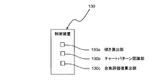
この制御装置130は、図14に示すように、撮像素子82により撮像されたチャート像に基づいて、SFR(空間周波数応答)を用いて撮影レンズ72により結像されたチャート像の結像面に対する撮像素子82の撮像面のX軸,Y軸,Z軸回りの傾きを算出する傾き算出部130aと、撮像素子82の撮像面上に予め設定された撮像位置に少なくとも一部が含まれるチャートパターンを認識するチャートパターン認識部130bと、チャートパターン認識部130bにより認識されたチャートパターンの位置を基準にして決定されるチャート像の各チャートパターンに対する評価領域を用いて合焦評価値を算出する合焦評価値算出部130cとを有する。
撮影レンズ72または撮像素子82をZ軸方向に移動させると、倍率変化によって、撮像ユニット3の撮像素子82の撮像面とチャートパターンの結像面との関係が変化する。一般的に、測定チャート1とレンズユニット2の撮影レンズ72との距離が近いほど、撮影レンズ72の移動による倍率の変化は大きい。
この第3実施形態の手法では、矩形のチャートパターンの例えば左側の辺のエッジを画像処理(パターンマッチング)によって検出し、その点から各像高に応じて、所定の領域を解析する処理を行っている。
上記第3実施形態の撮像素子の位置調整装置によれば、装置の安定した稼働が実現できると共に、調整精度を向上できる。
また、上記レンズユニット2または撮像ユニット3をZ軸方向の移動により画像倍率が変化して、撮像素子82の撮像面とチャート像の結像面との関係が変化しても、特定の撮像領域のチャートパターンを認識し、そのチャートパターンの位置を基準にして各チャートパターンの評価領域を決定するので、画像倍率の変化に伴って、レンズユニット2または撮像ユニット3をZ軸方向に移動させても、合焦評価値算出部130cにより合焦評価値を問題なく算出することができる。
上記第1~第3実施形態では、黒色の正方形状の複数のチャートパターン61,62などがチャート面に印刷された測定チャート1を備えた撮像素子の位置調整装置について説明したが、測定チャートのチャートパターンはこれに限らず、所定の間隔で直線を配列したラダー状のチャートパターンなどでもよい。
また、Z軸方向の移動と、Z軸に直交するX軸方向の移動と、Z軸かつX軸に直交するY軸方向の移動と、Z軸回りの回転と、X軸回りの回転と、Y軸回りの回転を行う機能を備えた6軸ステージを移動機構20として用いたが、撮像ユニット保持部により保持される撮像素子の撮像素子のZ軸回りの傾きが許容範囲内になるように撮像ユニット保持部により撮像ユニットを保持できる場合、移動機構は、Z軸回りの回転を行う機能を備えなくてもよい。
この発明の具体的な実施の形態について説明したが、この発明は上記第1~第3実施形態に限定されるものではなく、この発明の範囲内で種々変更して実施することができる。
また、特許文献2(特開2006-30256号公報)に記載された従来技術では、
(1) 測定チャート交換の機構が必要となる(測定チャートが固定されている場合は移動機構が必要)。
(2) 測定チャート交換時に機構の動作精度が必要となる(位置決め精度)。
(3) 測定チャートの枚数に応じてコストが増加する。
(4) 装置のスペースが大きい(チャート2枚分)。
という問題があるのに対して、この発明の撮像素子の位置調整装置では、合焦・撮像素子調整角度を同一の被写体(測定チャート)を用いて行っており、どちらも解像度で調整しており、この解像度は実際の写真のボケとほぼ相関があるため、人間の目で見た画像に近い結果が得られ、次のような(a)~(d)の特徴を有する。
(a) 組立時に調整するだけで良い。
(b) 測定チャートを交換する必要がない。
(c) 測定チャート1枚分のコストでよい。
(d) 測定チャート1枚分のスペースでよい。
(1) 測定チャート交換の機構が必要となる(測定チャートが固定されている場合は移動機構が必要)。
(2) 測定チャート交換時に機構の動作精度が必要となる(位置決め精度)。
(3) 測定チャートの枚数に応じてコストが増加する。
(4) 装置のスペースが大きい(チャート2枚分)。
という問題があるのに対して、この発明の撮像素子の位置調整装置では、合焦・撮像素子調整角度を同一の被写体(測定チャート)を用いて行っており、どちらも解像度で調整しており、この解像度は実際の写真のボケとほぼ相関があるため、人間の目で見た画像に近い結果が得られ、次のような(a)~(d)の特徴を有する。
(a) 組立時に調整するだけで良い。
(b) 測定チャートを交換する必要がない。
(c) 測定チャート1枚分のコストでよい。
(d) 測定チャート1枚分のスペースでよい。
この発明の撮像素子の位置調整装置は、
複数のチャートパターンが形成された測定チャート1と、
上記測定チャート1に直交するZ軸上に配置された撮影レンズ72が組み込まれたレンズユニット2を保持するためのレンズユニット保持部11と、
上記撮影レンズ72によって結像される上記測定チャート1のチャート像を撮像するように上記Z軸上に配置された撮像素子82が組み込まれた撮像ユニット3を保持するための撮像ユニット保持部20aと、
上記レンズユニット保持部11または上記撮像ユニット保持部20aのいずれか一方を、上記Z軸方向に沿って移動させる移動機構20と、
上記移動機構20により上記レンズユニット保持部11または上記撮像ユニット保持部20aのいずれか一方を上記Z軸方向に沿って移動させながら上記撮像素子82により撮像された上記測定チャートのチャート像に基づいて、上記撮像素子82のZ軸回りの傾きおよびそのZ軸に交わるX軸,Y軸回りの傾きを調整する傾き調整部20bと
を備え、
上記測定チャート1と上記撮影レンズ72との距離Lは、
200mm ≦ L ≦ 2000mm
の条件を満たすことを特徴とする。
複数のチャートパターンが形成された測定チャート1と、
上記測定チャート1に直交するZ軸上に配置された撮影レンズ72が組み込まれたレンズユニット2を保持するためのレンズユニット保持部11と、
上記撮影レンズ72によって結像される上記測定チャート1のチャート像を撮像するように上記Z軸上に配置された撮像素子82が組み込まれた撮像ユニット3を保持するための撮像ユニット保持部20aと、
上記レンズユニット保持部11または上記撮像ユニット保持部20aのいずれか一方を、上記Z軸方向に沿って移動させる移動機構20と、
上記移動機構20により上記レンズユニット保持部11または上記撮像ユニット保持部20aのいずれか一方を上記Z軸方向に沿って移動させながら上記撮像素子82により撮像された上記測定チャートのチャート像に基づいて、上記撮像素子82のZ軸回りの傾きおよびそのZ軸に交わるX軸,Y軸回りの傾きを調整する傾き調整部20bと
を備え、
上記測定チャート1と上記撮影レンズ72との距離Lは、
200mm ≦ L ≦ 2000mm
の条件を満たすことを特徴とする。
上記構成によれば、撮影レンズ72から近距離の位置に測定チャート1を配置することが可能になり、光軸方向だけでなく、幅方向・奥行き方向に対しても装置本体を小型化できる。
また、無限遠に相当する位置の被写体の像を撮像素子82の撮像面に結像させる撮影レンズ72の位置に対して、撮影レンズ72を被写体側に移動させるか、または、撮像素子82を被写体と反対の側に移動させて、撮影レンズ72と撮像素子82との間隔を広げて撮像素子82の傾き調整を行うことができ、アクティブアライメントによる撮像素子82・撮影レンズ72の調整角度が大きくても、低コストかつ省スペースな撮像素子の位置調整装置によって傾き調整のマージンを十分に確保することができる。
また、一実施形態の撮像素子の位置調整装置では、
上記測定チャート1と上記撮影レンズ72との距離Lは、
400mm ≦ L ≦ 1000mm
の条件を満たす。
上記測定チャート1と上記撮影レンズ72との距離Lは、
400mm ≦ L ≦ 1000mm
の条件を満たす。
また、一実施形態の撮像素子の位置調整装置では、
上記レンズユニット2と上記撮像ユニット3との間に有する空隙の少なくとも一部に接着剤を充填する充填部40を備えた。
上記レンズユニット2と上記撮像ユニット3との間に有する空隙の少なくとも一部に接着剤を充填する充填部40を備えた。
上記実施形態によれば、レンズユニット2と撮像ユニット3との空隙の少なくとも一部に充填部40により接着剤を充填することによって、傾き調整後にレンズユニット2との空隙がばらつく撮像ユニット3をレンズユニット2に容易に固定できる。
また、一実施形態の撮像素子の位置調整装置では、
上記充填部40は、上記撮像素子82のX軸,Y軸およびZ軸回りの角度を上記傾き調整部20bにより調整する前に、上記空隙の少なくとも一部に紫外線硬化型の接着剤または熱硬化型の接着剤の少なくとも一方を充填する。
上記充填部40は、上記撮像素子82のX軸,Y軸およびZ軸回りの角度を上記傾き調整部20bにより調整する前に、上記空隙の少なくとも一部に紫外線硬化型の接着剤または熱硬化型の接着剤の少なくとも一方を充填する。
上記実施形態によれば、傾き調整部20bによる調整する前に、レンズユニット2と撮像ユニット3との空隙の少なくとも一部に紫外線硬化型の接着剤または熱硬化型の接着剤の少なくとも一方を充填部40により充填することによって、撮像素子82の傾きを調整する前の状態でレンズユニット2と撮像ユニット3との間隔に接着剤を容易に充填できると共に、傾き調整後にレンズユニット2と撮像ユニット3との間隔が狭くなった箇所があっても、充填された接着剤に対して紫外線を照射するかまたは加熱することにより、レンズユニット2と撮像ユニット3とを確実かつ容易に接着できる。
また、一実施形態の撮像素子の位置調整装置では、
上記撮像素子82により撮像された上記チャート像に基づいて、SFR(空間周波数応答)を用いて上記撮影レンズ72により結像された上記チャート像の結像面に対する上記撮像素子82の撮像面のX軸,Y軸,Z軸回りの傾きを算出する傾き算出部130aを備え、
上記傾き調整部20bは、上記傾き算出部130aにより算出された上記撮像素子82の撮像面のX軸,Y軸,Z軸回りの傾きに基づいて、上記撮像素子82のX軸,Y軸,Z軸回りの傾きを調整する。
上記撮像素子82により撮像された上記チャート像に基づいて、SFR(空間周波数応答)を用いて上記撮影レンズ72により結像された上記チャート像の結像面に対する上記撮像素子82の撮像面のX軸,Y軸,Z軸回りの傾きを算出する傾き算出部130aを備え、
上記傾き調整部20bは、上記傾き算出部130aにより算出された上記撮像素子82の撮像面のX軸,Y軸,Z軸回りの傾きに基づいて、上記撮像素子82のX軸,Y軸,Z軸回りの傾きを調整する。
上記実施形態によれば、撮像素子82により複数のZ座標で夫々撮像されたチャート像に基づいて、SFR(空間周波数応答)を用いて撮影レンズ72により結像されたチャート像の結像面に対する撮像素子82の撮像面のX軸,Y軸,Z軸回りの傾きを傾き算出部130aにより算出するので、SFR(空間周波数応答)により不鮮明な画像からでも精度よく合焦評価ができ、撮影レンズ72により結像されたチャート像の結像面に対する撮像素子82の撮像面のX軸,Y軸,Z軸回りの傾きを正確に算出することができる。
1…測定チャート
2…レンズユニット
3…撮像ユニット
10…レンズ位置決め治具
11…レンズ保持機構
12,21…吸着パッド
13,14…位置決めピン
20…移動機構
20a…撮像ユニット保持部
20b…傾き調整部
30,130…制御装置
30a,130a…傾き算出部
40…接着剤塗布装置
50…UV照射機
61,62,63…チャートパターン
71…ユニット本体
72…撮影レンズ
73…VCM
81…基板
82…撮像素子
130b…チャートパターン認識部
130c…合焦評価値算出部
2…レンズユニット
3…撮像ユニット
10…レンズ位置決め治具
11…レンズ保持機構
12,21…吸着パッド
13,14…位置決めピン
20…移動機構
20a…撮像ユニット保持部
20b…傾き調整部
30,130…制御装置
30a,130a…傾き算出部
40…接着剤塗布装置
50…UV照射機
61,62,63…チャートパターン
71…ユニット本体
72…撮影レンズ
73…VCM
81…基板
82…撮像素子
130b…チャートパターン認識部
130c…合焦評価値算出部
Claims (5)
- 複数のチャートパターンが形成された測定チャート(1)と、
上記測定チャート(1)に直交するZ軸上に配置された撮影レンズが組み込まれたレンズユニット(2)を保持するためのレンズユニット保持部(11)と、
上記撮影レンズ(72)によって結像される上記測定チャート(1)のチャート像を撮像するように上記Z軸上に配置された撮像素子が組み込まれた撮像ユニット(3)を保持するための撮像ユニット保持部(20a)と、
上記レンズユニット保持部(11)または上記撮像ユニット保持部(20a)のいずれか一方を、上記Z軸方向に沿って移動させる移動機構(20)と、
上記移動機構(20)により上記レンズユニット保持部(11)または上記撮像ユニット保持部(20a)のいずれか一方を上記Z軸方向に沿って移動させながら上記撮像素子(82)により撮像された上記測定チャート(1)のチャート像に基づいて、上記撮像素子(82)のZ軸回りの傾きおよびそのZ軸に交わるX軸,Y軸回りの傾きを調整する傾き調整部(20b)と
を備え、
上記測定チャート(1)と上記撮影レンズ(72)との距離Lは、
200mm ≦ L ≦ 2000mm
の条件を満たすことを特徴とする撮像素子の位置調整装置。 - 請求項1に記載の撮像素子の位置調整装置において、
上記測定チャート(1)と上記撮影レンズ(72)との距離Lは、
400mm ≦ L ≦ 1000mm
の条件を満たすことを特徴とする撮像素子の位置調整装置。 - 請求項1または2に記載の撮像素子の位置調整装置において、
上記レンズユニット(2)と上記撮像ユニット(3)との間に有する空隙の少なくとも一部に接着剤を充填する充填部(40)を備えたことを特徴とする撮像素子の位置調整装置。 - 請求項3に記載の撮像素子の位置調整装置において、
上記充填部(40)は、上記撮像素子(82)のX軸,Y軸およびZ軸回りの角度を上記傾き調整部(20b)により調整する前に、上記空隙の少なくとも一部に紫外線硬化型の接着剤または熱硬化型の接着剤の少なくとも一方を充填することを特徴とする撮像素子の位置調整装置。 - 請求項1から4までのいずれか1つに記載の撮像素子の位置調整装置において、
上記撮像素子(82)により撮像された上記チャート像に基づいて、SFR(空間周波数応答)を用いて上記撮影レンズ(72)により結像された上記チャート像の結像面に対する上記撮像素子(82)の撮像面のX軸,Y軸,Z軸回りの傾きを算出する傾き算出部(130a)を備え、
上記傾き調整部(20b)は、上記傾き算出部(130a)により算出された上記撮像素子(82)の撮像面のX軸,Y軸,Z軸回りの傾きに基づいて、上記撮像素子(82)のX軸,Y軸,Z軸回りの傾きを調整することを特徴とする撮像素子の位置調整装置。
Applications Claiming Priority (2)
| Application Number | Priority Date | Filing Date | Title |
|---|---|---|---|
| JP2013-051992 | 2013-03-14 | ||
| JP2013051992A JP2014179764A (ja) | 2013-03-14 | 2013-03-14 | 撮像素子の位置調整装置 |
Publications (1)
| Publication Number | Publication Date |
|---|---|
| WO2014141497A1 true WO2014141497A1 (ja) | 2014-09-18 |
Family
ID=51536187
Family Applications (1)
| Application Number | Title | Priority Date | Filing Date |
|---|---|---|---|
| PCT/JP2013/071786 Ceased WO2014141497A1 (ja) | 2013-03-14 | 2013-08-12 | 撮像素子の位置調整装置 |
Country Status (2)
| Country | Link |
|---|---|
| JP (1) | JP2014179764A (ja) |
| WO (1) | WO2014141497A1 (ja) |
Cited By (1)
| Publication number | Priority date | Publication date | Assignee | Title |
|---|---|---|---|---|
| US20210080675A1 (en) * | 2019-09-16 | 2021-03-18 | Sang Shin BAE | Optical axis alignment apparatus of camera module |
Families Citing this family (2)
| Publication number | Priority date | Publication date | Assignee | Title |
|---|---|---|---|---|
| KR102544085B1 (ko) * | 2020-02-26 | 2023-06-15 | 가부시키가이샤 피에프에이 | 카메라 모듈 제조 장치 |
| JP2025042796A (ja) * | 2023-09-15 | 2025-03-28 | 株式会社Screenホールディングス | 光学素子保持ユニットおよび描画装置 |
Citations (5)
| Publication number | Priority date | Publication date | Assignee | Title |
|---|---|---|---|---|
| JPH04235490A (ja) * | 1991-01-10 | 1992-08-24 | Toshiba Corp | 固体撮像センサの位置調整装置 |
| JP2005136743A (ja) * | 2003-10-30 | 2005-05-26 | Kyocera Corp | 撮像素子の位置調整装置及び位置調整方法 |
| JP2006030256A (ja) * | 2004-07-12 | 2006-02-02 | Mitsubishi Electric Corp | 撮像装置の焦点調整方法および焦点調整装置 |
| WO2009110528A1 (ja) * | 2008-03-06 | 2009-09-11 | シャープ株式会社 | 固体撮像装置用テストチャート及びその使用方法、チャート盤、テスト装置 |
| WO2013035514A1 (ja) * | 2011-09-05 | 2013-03-14 | コニカミノルタアドバンストレイヤー株式会社 | カメラモジュールの製造方法及びカメラモジュール |
-
2013
- 2013-03-14 JP JP2013051992A patent/JP2014179764A/ja active Pending
- 2013-08-12 WO PCT/JP2013/071786 patent/WO2014141497A1/ja not_active Ceased
Patent Citations (5)
| Publication number | Priority date | Publication date | Assignee | Title |
|---|---|---|---|---|
| JPH04235490A (ja) * | 1991-01-10 | 1992-08-24 | Toshiba Corp | 固体撮像センサの位置調整装置 |
| JP2005136743A (ja) * | 2003-10-30 | 2005-05-26 | Kyocera Corp | 撮像素子の位置調整装置及び位置調整方法 |
| JP2006030256A (ja) * | 2004-07-12 | 2006-02-02 | Mitsubishi Electric Corp | 撮像装置の焦点調整方法および焦点調整装置 |
| WO2009110528A1 (ja) * | 2008-03-06 | 2009-09-11 | シャープ株式会社 | 固体撮像装置用テストチャート及びその使用方法、チャート盤、テスト装置 |
| WO2013035514A1 (ja) * | 2011-09-05 | 2013-03-14 | コニカミノルタアドバンストレイヤー株式会社 | カメラモジュールの製造方法及びカメラモジュール |
Cited By (2)
| Publication number | Priority date | Publication date | Assignee | Title |
|---|---|---|---|---|
| US20210080675A1 (en) * | 2019-09-16 | 2021-03-18 | Sang Shin BAE | Optical axis alignment apparatus of camera module |
| US11644634B2 (en) * | 2019-09-16 | 2023-05-09 | Furonteer Inc | Optical axis alignment apparatus of camera module |
Also Published As
| Publication number | Publication date |
|---|---|
| JP2014179764A (ja) | 2014-09-25 |
Similar Documents
| Publication | Publication Date | Title |
|---|---|---|
| CN105556946B (zh) | 摄像模块的制造方法及摄像模块的制造装置 | |
| CN101666957B (zh) | 拍摄装置中的自动焦点调整方法 | |
| CN113302725B (zh) | 安装装置和安装方法 | |
| JP2022541026A (ja) | 撮影機器及び方法、並びに調整要素 | |
| US9906695B2 (en) | Manufacturing method of imaging module and imaging module manufacturing apparatus | |
| CN105308951A (zh) | 定位装置、定位方法及复眼照相机组件 | |
| JP5990655B2 (ja) | 撮像モジュール、撮像モジュールの製造方法、電子機器 | |
| US9791659B2 (en) | Imaging module and electronic device | |
| KR101549139B1 (ko) | 카메라 모듈 조립 방법 및 장치 | |
| WO2014141497A1 (ja) | 撮像素子の位置調整装置 | |
| CN105474620B (zh) | 摄像模块的制造方法及摄像模块的制造装置 | |
| JP7012977B2 (ja) | カメラモジュール製造装置 | |
| US9609196B2 (en) | Imaging module and electronic device | |
| US10015401B2 (en) | Imaging module, manufacturing method of imaging module, and electronic device | |
| CN113824853B (zh) | 摄像模组组装方法和设备 | |
| WO2015060188A1 (ja) | 撮像モジュールの製造方法及び撮像モジュールの製造装置 | |
| US10020342B2 (en) | Image pickup module manufacturing method, and image pickup module manufacturing device | |
| KR102325610B1 (ko) | 손떨림보정용 엑츄에이터 검사 장치 및 방법 | |
| CN120883740A (zh) | 定位装置、安装装置、处理装置、定位方法、电子部件的制造方法以及处理方法 | |
| JP6072511B2 (ja) | 位置調整装置、および位置調整方法 | |
| TW201517621A (zh) | 攝影模組的製造方法以及攝影模組的製造裝置 |
Legal Events
| Date | Code | Title | Description |
|---|---|---|---|
| 121 | Ep: the epo has been informed by wipo that ep was designated in this application |
Ref document number: 13877605 Country of ref document: EP Kind code of ref document: A1 |
|
| NENP | Non-entry into the national phase |
Ref country code: DE |
|
| 122 | Ep: pct application non-entry in european phase |
Ref document number: 13877605 Country of ref document: EP Kind code of ref document: A1 |