WO2014141486A1 - Uninterruptible power source apparatus - Google Patents
Uninterruptible power source apparatus Download PDFInfo
- Publication number
- WO2014141486A1 WO2014141486A1 PCT/JP2013/057560 JP2013057560W WO2014141486A1 WO 2014141486 A1 WO2014141486 A1 WO 2014141486A1 JP 2013057560 W JP2013057560 W JP 2013057560W WO 2014141486 A1 WO2014141486 A1 WO 2014141486A1
- Authority
- WO
- WIPO (PCT)
- Prior art keywords
- power supply
- unit
- battery
- power
- supply unit
- Prior art date
Links
Images


Classifications
-
- H—ELECTRICITY
- H02—GENERATION; CONVERSION OR DISTRIBUTION OF ELECTRIC POWER
- H02J—CIRCUIT ARRANGEMENTS OR SYSTEMS FOR SUPPLYING OR DISTRIBUTING ELECTRIC POWER; SYSTEMS FOR STORING ELECTRIC ENERGY
- H02J1/00—Circuit arrangements for dc mains or dc distribution networks
- H02J1/08—Three-wire systems; Systems having more than three wires
-
- H—ELECTRICITY
- H02—GENERATION; CONVERSION OR DISTRIBUTION OF ELECTRIC POWER
- H02J—CIRCUIT ARRANGEMENTS OR SYSTEMS FOR SUPPLYING OR DISTRIBUTING ELECTRIC POWER; SYSTEMS FOR STORING ELECTRIC ENERGY
- H02J1/00—Circuit arrangements for dc mains or dc distribution networks
- H02J1/10—Parallel operation of dc sources
- H02J1/102—Parallel operation of dc sources being switching converters
-
- H—ELECTRICITY
- H02—GENERATION; CONVERSION OR DISTRIBUTION OF ELECTRIC POWER
- H02J—CIRCUIT ARRANGEMENTS OR SYSTEMS FOR SUPPLYING OR DISTRIBUTING ELECTRIC POWER; SYSTEMS FOR STORING ELECTRIC ENERGY
- H02J7/00—Circuit arrangements for charging or depolarising batteries or for supplying loads from batteries
- H02J7/34—Parallel operation in networks using both storage and other dc sources, e.g. providing buffering
- H02J7/345—Parallel operation in networks using both storage and other dc sources, e.g. providing buffering using capacitors as storage or buffering devices
-
- H—ELECTRICITY
- H02—GENERATION; CONVERSION OR DISTRIBUTION OF ELECTRIC POWER
- H02J—CIRCUIT ARRANGEMENTS OR SYSTEMS FOR SUPPLYING OR DISTRIBUTING ELECTRIC POWER; SYSTEMS FOR STORING ELECTRIC ENERGY
- H02J7/00—Circuit arrangements for charging or depolarising batteries or for supplying loads from batteries
- H02J7/34—Parallel operation in networks using both storage and other dc sources, e.g. providing buffering
- H02J7/35—Parallel operation in networks using both storage and other dc sources, e.g. providing buffering with light sensitive cells
-
- H—ELECTRICITY
- H02—GENERATION; CONVERSION OR DISTRIBUTION OF ELECTRIC POWER
- H02J—CIRCUIT ARRANGEMENTS OR SYSTEMS FOR SUPPLYING OR DISTRIBUTING ELECTRIC POWER; SYSTEMS FOR STORING ELECTRIC ENERGY
- H02J9/00—Circuit arrangements for emergency or stand-by power supply, e.g. for emergency lighting
- H02J9/04—Circuit arrangements for emergency or stand-by power supply, e.g. for emergency lighting in which the distribution system is disconnected from the normal source and connected to a standby source
- H02J9/06—Circuit arrangements for emergency or stand-by power supply, e.g. for emergency lighting in which the distribution system is disconnected from the normal source and connected to a standby source with automatic change-over, e.g. UPS systems
- H02J9/062—Circuit arrangements for emergency or stand-by power supply, e.g. for emergency lighting in which the distribution system is disconnected from the normal source and connected to a standby source with automatic change-over, e.g. UPS systems for AC powered loads
-
- H—ELECTRICITY
- H02—GENERATION; CONVERSION OR DISTRIBUTION OF ELECTRIC POWER
- H02J—CIRCUIT ARRANGEMENTS OR SYSTEMS FOR SUPPLYING OR DISTRIBUTING ELECTRIC POWER; SYSTEMS FOR STORING ELECTRIC ENERGY
- H02J2300/00—Systems for supplying or distributing electric power characterised by decentralized, dispersed, or local generation
- H02J2300/20—The dispersed energy generation being of renewable origin
- H02J2300/28—The renewable source being wind energy
-
- Y—GENERAL TAGGING OF NEW TECHNOLOGICAL DEVELOPMENTS; GENERAL TAGGING OF CROSS-SECTIONAL TECHNOLOGIES SPANNING OVER SEVERAL SECTIONS OF THE IPC; TECHNICAL SUBJECTS COVERED BY FORMER USPC CROSS-REFERENCE ART COLLECTIONS [XRACs] AND DIGESTS
- Y02—TECHNOLOGIES OR APPLICATIONS FOR MITIGATION OR ADAPTATION AGAINST CLIMATE CHANGE
- Y02B—CLIMATE CHANGE MITIGATION TECHNOLOGIES RELATED TO BUILDINGS, e.g. HOUSING, HOUSE APPLIANCES OR RELATED END-USER APPLICATIONS
- Y02B10/00—Integration of renewable energy sources in buildings
- Y02B10/70—Hybrid systems, e.g. uninterruptible or back-up power supplies integrating renewable energies
-
- Y—GENERAL TAGGING OF NEW TECHNOLOGICAL DEVELOPMENTS; GENERAL TAGGING OF CROSS-SECTIONAL TECHNOLOGIES SPANNING OVER SEVERAL SECTIONS OF THE IPC; TECHNICAL SUBJECTS COVERED BY FORMER USPC CROSS-REFERENCE ART COLLECTIONS [XRACs] AND DIGESTS
- Y02—TECHNOLOGIES OR APPLICATIONS FOR MITIGATION OR ADAPTATION AGAINST CLIMATE CHANGE
- Y02E—REDUCTION OF GREENHOUSE GAS [GHG] EMISSIONS, RELATED TO ENERGY GENERATION, TRANSMISSION OR DISTRIBUTION
- Y02E10/00—Energy generation through renewable energy sources
- Y02E10/70—Wind energy
- Y02E10/76—Power conversion electric or electronic aspects
Definitions
- the present invention relates to an uninterruptible power supply apparatus that can be constructed in a space-saving manner, for example, in a power supply system that is installed in a data center and supplies power to a plurality of servers (load devices) that constitute a multi-node server.
- FIG. 12 is a schematic configuration diagram of a conventional general power supply system in a data center including a plurality of load devices using a DC voltage as a driving power source, for example, a plurality of servers.
- This power supply system includes an uninterruptible power supply (UPS) 1 interposed in a 400V system power supply and high-voltage AC power (AC400V) fed via the uninterruptible power supply 1, for example, 200V or And an AC power supply distributor (PDU) 2 for converting into 100V AC power.
- UPS uninterruptible power supply
- AC400V high-voltage AC power
- PDU AC power supply distributor
- the uninterruptible power supply 1 basically includes a large capacity battery (BAT) 1a capable of storing DC power.
- the uninterruptible power supply 1 includes an AC / DC converter 1b that converts the high-voltage AC power into a DC voltage to charge the battery 1a, an output voltage of the AC / DC converter 1b, or the battery 1a. And a DC / AC converter 1c that converts the DC power stored in the battery into high-voltage AC power and outputs it.
- the power distribution unit 2 includes a circuit breaker 2a that separates, for example, the system power supply and the load facility side including the load device (server).
- the AC power supply distributor 2 further includes a transformer 2b that converts the high-voltage AC power (AC 400V) into, for example, 200V AC power and outputs it.
- reference numeral 3 denotes a transformer which converts, for example, 6.6 kV transmission AC power into the high-voltage AC power (AC 400 V) and draws it into the building where the uninterruptible power supply 1 and the like are provided.
- the load equipment constructed by including a plurality of servers 4 as the load devices is connected to the power supply distributor 2 at the front stage thereof, and is the drive power supply voltage of the server 4 from the AC power (AC200V).
- a switching power supply 5 that generates low-voltage direct current power (for example, DC12V) of 48V or less is provided.
- the switching power supply 5 generally includes an AC / DC converter 5a that converts the AC power (AC 200V) into a DC voltage, and a DC output voltage that supplies the output voltage of the AC / DC converter 5a to the server 4. And a DC / DC converter 5b for conversion to (DC12V).
- the plurality of servers 4 are respectively connected to the switching power supply 5 and are operated by being supplied with the DC output voltage, which is a driving power supply for the server 4, from the switching power supply 5 (see, for example, Patent Document 1).
- the plurality of servers 4 are generally installed in a server rack by storing a predetermined number of servers 4 so as to form a server group, and the switching power supply 5 is provided corresponding to each server group.
- the switching power supply 5 is housed in the server rack together with the predetermined number of servers 4.
- the conventional general power supply system configured as described above has a large number of conversion stages such as the AC / DC converters 1b and 5a and the DC / DC converter 5b described above, and conversion efficiency with respect to power is poor. Therefore, a power supply system in which a DC power supply system as shown in FIGS. 13 and 14 is constructed has been proposed.
- the power supply system shown in FIG. 13 directly feeds the high-voltage DC power (DC 400V) obtained from the AC / DC converter 1b of the uninterruptible power supply 1 to the DC power supply distributor 2.
- the high-voltage direct current power fed through the power distributor 2a is input to a switching power source 5 including a DC / DC converter 5d, and the switching power source 5 (DC / DC converter 5d) is input.
- DC 12 V DC output voltage
- This type of power supply system is called, for example, a high-voltage DC power supply system (HVCD) (see, for example, Non-Patent Document 1).
- HVCD high-voltage DC power supply system
- the power supply system shown in FIG. 14 uses high voltage direct current power (DC400V) obtained from the AC / DC converter 1b of the uninterruptible power supply 1 as a DC / DC converter 1d provided in the uninterruptible power supply 1. Then, the power is converted to a low DC voltage (DC48V) and supplied to the DC power supply distributor 2a. On the load device side, the DC low voltage fed from the power supply distributor 2a is input to the switching power supply 5 including the DC / DC converter 5e, and the switching power supply 5 (DC / DC converter 5e) The server 4 is configured to generate a DC output voltage (DC 12 V) that supplies power to each server 4.
- This type of power supply system is called, for example, a low-voltage DC power supply system (see, for example, Non-Patent Document 2).
- Patent Document 2 discloses that the uninterruptible power supply is operated in parallel.
- Patent Document 3 discloses that when the number of parallel operations of the uninterruptible power supply apparatus is increased, only the batteries are connected in parallel by switching the switch, thereby changing the battery capacity.
- the present invention has been made in consideration of such circumstances, and an object of the present invention is, for example, to provide a power supply system that supplies power to a load device composed of a plurality of servers in a compact and space-saving manner, and to achieve a required power capacity.
- An object of the present invention is to provide an uninterruptible power supply that can be easily constructed in response.
- the uninterruptible power supply according to the present invention to achieve the above-described object is A power supply unit that houses a power supply circuit unit that converts alternating current power and generates a direct current voltage for supplying power to a load device in a casing of a predetermined size;
- a battery circuit unit that is provided side by side in the power supply unit and stores DC power, and generates a DC voltage that discharges the stored DC power and supplies power to the load device is housed in a casing having the same dimensions as the power supply unit.
- a battery unit; The power supply unit and the battery unit are detachably mounted, and a rack for connecting the power supply circuit portion of the power supply unit and the battery circuit portion of the battery unit in parallel is provided.
- the rack is detachably attached to the power supply unit and the battery unit from the front side of the rack, and is provided in each housing of the power supply unit and the battery unit on the back side of the rack.
- the power supply circuit unit is connected to the circuit unit via a connector, and the connection unit is connected to the power supply unit and the battery unit in parallel.
- connection structure is composed of an AC power supply line connected to the system power supply and a DC power line for supplying a DC voltage to the load device.
- the battery unit is connected in parallel to the power supply unit via the DC power line, and the battery circuit unit inputs a DC voltage output from the power supply unit and outputs the DC to the battery. It comprises a DC / DC converter that stores electric power and generates a DC voltage for supplying power to the load device from DC power stored in the battery.
- the connector is connected to the rack when the power supply unit or the battery unit is attached to the rack, and is disconnected when the power supply unit or the battery unit is removed from the rack.
- the connection structure is configured to include the other one of the plug and the plug seat.
- connection structure is provided across a plurality of storage areas of the rack on which the power supply unit or the battery unit is selectively mounted.
- connection structure is provided with a terminal portion in which the DC power line is separated between the adjacent storage areas, and the DC power line is connected in parallel or in series via a terminal unit attached to the terminal portion. It is desirable to realize as a structure.
- the battery circuit unit is provided with a DC / AC converter that generates AC power supplied from the power supply unit from DC power stored in the battery and outputs the AC power to the AC power supply line. Further, the battery circuit unit is connected to a power supply input system provided separately from the AC power supply line, and the battery is configured to convert the power obtained from the solar power generation device or the wind power generation device via the power supply input system to the voltage. It is also desirable to provide a converter for storing electricity.
- the rack has a size conforming to the EIA standard in which, for example, a plurality of load devices can be mounted vertically
- the casing of the predetermined size in which the power supply unit and the battery unit are individually stored
- the basic storage size of the rack or the division size obtained by dividing this basic storage size into N equal parts (N is a natural number of 2 or more) in the width direction is realized. It is desirable that the power supply unit and the battery unit are mounted on the rack together with a predetermined number of load devices.
- the power supply unit is individually provided for each phase of the three-phase AC power supply.
- a plurality of the battery units may be provided in parallel with respect to one power supply unit.
- Each of the power supply unit and the battery unit is provided with a fan device that causes air to flow inside the housings to release heat in the power supply circuit unit and the battery circuit unit. It is desirable that the power supply circuit unit and the battery circuit unit are driven even when operation is stopped.
- the power supply unit and the battery unit are configured separately, and the power supply unit and the battery circuit unit are connected in parallel by storing these power supply units and the battery unit in a rack, respectively. Therefore, the power supply system can be easily built according to the load specifications. Moreover, it is easy to increase the power capacity by easily adding battery units connected in parallel to the power supply unit.
- the power supply unit and the battery unit constituting the uninterruptible power supply using, for example, an empty space of a rack that stores a plurality of load devices (servers). Therefore, there is no need to secure a dedicated space for installing the uninterruptible power supply in the data center unlike the conventional power supply system in which a large-capacity uninterruptible power supply is centrally arranged in the system power supply. Can be built. Further, the power supply circuit unit and the battery circuit unit are individually housed in a casing having the same dimensions to constitute the power supply unit and the battery unit, respectively. It can be constructed at a low cost as a unit having a capacity. Therefore, it is possible to construct the uninterruptible power supply apparatus at a low cost as a whole.
- assembled with the uninterruptible power supply which concerns on one Embodiment of this invention The figure which shows the example of the mounting
- FIG. 1 is a schematic configuration diagram of a power supply system 100 constructed using the uninterruptible power supply according to the embodiment.
- the power supply system 100 is suitable for supplying a DC voltage of 12V, which is a drive source of the server 4, to each of a plurality of servers (load devices) 4 provided in a data center and constructing a multi-node server, for example. Is.
- the same parts as those of the conventional power supply system are denoted by the same reference numerals.
- the power supply system 100 includes an AC power supply distributor (PDU) 2 connected to a 400 V system power supply, and a server rack that houses a plurality of the servers (load devices) 4 via the power supply distributor 2.
- the AC power is supplied to 40.
- the power supply system 100 shown in FIG. 1 includes a transformer 2b in the power supply distributor 2, converts high-voltage AC power (AC400V) fed from the system power supply into 200V AC power, and converts it to the load side (server rack). 40).
- AC power AC 400V
- the AC power may be supplied to the load side via the power distributor 2 as it is.
- the server rack 40 in which a plurality of the servers (load devices) 4 are accommodated, there is no power supply unit 20 and a battery unit 30 corresponding to each of a server group including a predetermined number of servers 4.
- a power failure power supply 10 is provided.
- the power supply unit 20 is configured by storing a power supply circuit unit 21 constituting a main body thereof in a casing of a predetermined size that can be mounted on the server rack 40.
- the power supply circuit unit 21 includes an AC / DC converter 22 that converts the AC power (AC200V / AC400V) into a DC voltage. Further, the power supply circuit unit 21 includes a DC / DC converter 23 that converts the output voltage of the AC / DC converter 22 into a DC voltage (DC 12 V) that supplies power to the server 4.
- the power supply circuit unit 21 corresponds to the switching power supply 5 shown in FIG. Accordingly, the AC / DC converter 22 and the DC / DC converter 23 constituting the power supply circuit unit 21 correspond to the AC / DC converter 5a and the DC / DC converter 5b in the switching power supply 5, respectively. .
- the battery unit 30 is configured by housing the battery circuit unit 31 constituting the main body in a casing having the same dimensions as the casing of the power supply unit 20.
- the battery unit 30 is provided side by side with the power supply unit 20 and is operated in parallel with the power supply unit 20.
- the battery unit 30 (battery circuit unit 31) stores DC power during operation of the power supply unit 20 (power supply circuit unit 21), and discharges the stored DC power to generate the DC voltage (DC12V).
- the uninterruptible power supply 10 constructed by including the power supply unit 20 and the battery unit 30 in parallel has a power supply function for the server (load device) 4 unlike the uninterruptible power supply 1 described above. Construct a DC output type uninterruptible power supply.
- the battery circuit unit 31 includes a battery 32 such as a Li ion battery capable of storing DC power. Further, as shown in FIG. 1, the battery circuit unit 31 includes a bidirectional DC / DC converter 33 that is connected to a voltage output terminal of the DC / DC converter 23 and selectively charges and discharges the battery 32. Composed. In this case, the bidirectional DC / DC converter 33 receives the above-mentioned 12V DC voltage and charges the battery 32 to store DC power. Further, the bidirectional DC / DC converter 33 generates and outputs the 12V DC voltage to be supplied to the server (load device) 4 from the DC power stored in the battery 32.
- the bidirectional DC / DC converter 33 generates and outputs the 12V DC voltage to be supplied to the server (load device) 4 from the DC power stored in the battery 32.
- the battery circuit unit 31 is charged with the battery 32 using an AC / DC converter 34 that converts the AC voltage (AC 200V / AC 400V) into a DC voltage. It is also possible to configure. In this case, in place of the bidirectional DC / DC converter 33, a function of merely generating the 12V DC voltage for supplying power to the server (load device) 4 from the DC power stored in the battery 32 is provided. It is sufficient to use a DC / DC converter 35.
- the battery unit 30 is provided in parallel to the power supply unit 20 and is operably provided with the power supply unit 20.
- “being operable at the same time” not only means that the battery 32 is charged when the power supply unit 20 is operated, but also is stored in the battery 32 when the power supply unit 20 is operated, as will be described later. It also means that the DC voltage (DC12V) is generated by discharging the DC power.
- the AC / DC converters 22 and 34 play a role of converting high voltage AC power (AC 400V) into a predetermined DC voltage (DC 800V), for example, as described above.
- the semiconductor switching element for example, a MOS-FET or IGBT
- each of the AC / DC converters 22 and 34 is preferably configured using, for example, a neutral point clamp type three-level power conversion circuit.
- this type of neutral point clamp type three-level power conversion circuit is introduced in detail in, for example, Japanese Patent Application Laid-Open Nos. 2012-253981 and 2011-223867. According to the neutral-point clamp type three-level power conversion circuit, the voltage applied to the semiconductor switching element can be suppressed to about 1 ⁇ 2 of the input voltage.
- the AC / DC converters 22 and 34 can be constructed in a compact manner by using relatively inexpensive semiconductor switching elements having a withstand voltage of about 600 V and excellent performance.
- the power conversion efficiency itself can be increased by suppressing the loss in the semiconductor switching element. Therefore, in combination with the fact that the battery 32 can be reduced in size and weight using, for example, a small and large-capacity Li ion battery, the power supply circuit unit 21 including the DC / DC converter 23 described above and the like.
- Each of the battery circuit portions 31 can be configured compactly.
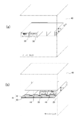
- the power supply unit 20 and the battery unit 30 configured as described above are server racks having dimensions conforming to the EIA standard in which a plurality of servers (load devices) 4 can be mounted vertically as shown in FIG. 40 is removably accommodated in each.
- the housing that houses the power supply circuit unit 21 and constructs the power supply unit 20 has the basic storage size of the server rack 40, and in particular, divides the basic storage size into N equal parts in the width direction (N is 2 or more). (Natural number) of division size.
- the casing is made of a so-called one-unit size (1U size) that is divided into four equal parts in the width direction (here, abbreviated as 1U4 size).
- the housing that houses the battery circuit unit 31 and constructs the battery unit 30 also has a 1U4 size that is the same size as the power supply unit 20.
- the power supply unit 20 and the battery unit 30 are shown in FIG. 2A when the server rack 40 is viewed from the front (front) side, and in FIG. Are stored side by side in the server rack 40 as shown in FIG.
- the power supply unit 20 and the battery unit 30 are detachably attached to the server rack 40 from the front side of the server rack 40, respectively.
- connection structure 41 for connecting the power supply unit 20 and the battery unit 30 in parallel is provided on the back side of the server rack 40 as shown in FIG.
- This connection structure 41 is basically connected to the system power supply and supplied with an AC power supply line 42 that supplies an AC voltage (AC200V / AC400V), and a DC voltage that supplies a DC voltage (DC12V) to the server (load device). And a power line 43.
- the connection structure 41 is coupled to the power supply unit 20 and the battery unit 30 via connectors described later.
- the connector 44 provided on the back side of each housing of the power supply unit 20 and the battery unit 30 is composed of one of a plug-in pair and a plug seat.
- the connection structure 41 is provided with the other of the plug and the plug seat.
- the plug-in pair of connectors 44 are connected to the server rack 40 when the power supply unit 20 or the battery unit 30 is mounted, and the server rack of the power supply unit 20 or the battery unit 30 is connected. The connection is released along with the removal from 40.
- the connector 44 serves to connect the power supply circuit unit 21 and the battery circuit unit 31 to the AC power supply line 42 and the DC power line 43, respectively, thereby connecting the power supply unit 20 and the battery unit 30 in parallel. Take on.
- the battery circuit unit 31 is configured to charge the battery 32 by inputting the DC voltage (DC 12V) output from the power circuit unit 21 as described above, the battery circuit unit 31 is provided in the battery unit 30.
- the connector 44 connected connects the battery circuit unit 31 only to the DC power line 43.
- FIGS. 3 (a) and 3 (b) show an example in which single-phase AC power (AC200V) is input.
- the power supply unit 20 has three-phase AC power. It is provided individually for each phase (R, S, T) of the AC power supply.
- the battery unit 30 is provided for each power supply unit 20. In this case, for example, as shown in FIGS. 3 (a) and 3 (b), two rows of storage stages adjacent to each other in the vertical direction of the server rack 40 are used, and the phases for the respective phases (R, S, T).
- the power supply unit 20 and the battery unit 30 are housed side by side.
- connection structure 41 As shown in FIGS. 3A and 3B, the AC power supply line 42 and the DC power line straddle the plurality of storage stages arranged in the vertical direction of the server rack 40. 43 is extended. It is sufficient that the AC power supply line 42 and the DC power line 43 extending in the vertical direction are provided along a support column provided on the back side of the server rack 40. Further, although not shown here, it goes without saying that the connection structure 41 is also provided to extend to other storage stages for storing the server (load equipment) 4 of the server rack 40. Then, a DC voltage (DC 12 V) is supplied to the server (load device) 4 through the DC power line 43 of the connection structure 41.
- DC 12 V DC voltage
- the expansion form of the uninterruptible power supply 10 will be briefly described.
- the power supply unit 20 and the battery unit 30 are each realized in a 1U4 size as described above, so basically two power supply units 20 and two battery units are provided. 30 and stored in a row in the storage stage of the server rack 40 side by side as shown in FIG. Further, when increasing the battery capacity, for example, as shown in FIG. 4B, the battery unit 30 may be added and stored in a storage stage adjacent to the power supply unit 20. Furthermore, when the power capacity itself for the server (load device) 4 is increased, for example, the battery unit 30 may be added together with the power unit 20 as shown in FIG.
- the battery unit 30 may be added to increase the battery capacity.
- FIG. 5B it is of course possible to increase the power supply capacity itself for the server (load device) 4 by adding the power supply unit 20 and the battery unit 30 respectively. In this case, it is desirable to store the power supply unit 20 and the battery unit 30 side by side in each of the three vertical storage stages.
- the power supply unit 20 and the battery unit 30 in the uninterruptible power supply 10 are the same size and are individually configured. Accordingly, the power supply unit 20 and the battery unit 30 can be appropriately added according to the power capacity required for the uninterruptible power supply 10 and according to the backup time of the battery unit 30 at the time of a power failure of the AC power supply. . Therefore, this uninterruptible power supply 10 is rich in expandability, and can construct the power supply system 100 according to various specifications.
- FIG. 6 shows a schematic configuration example of the connection structure 41, in which 44 denotes a connector connected to the AC power supply line 42 and the DC power line 43. These connectors 44 are provided for each storage area of the power supply unit 20 and / or the battery unit 30 obtained by dividing one storage area in the server rack 40 into four in the width direction.
- connection structure 41 is provided with a plurality of terminal portions 45 that separate the DC power line 43 between the adjacent storage areas.
- These terminal portions 45 play a role of sequentially connecting the DC power lines 43 in series via the terminal units when a terminal unit (not shown) is mounted. Therefore, when the terminal unit is removed, the DC power line 43 is disconnected at the mounting position of the terminal portion 45. By disconnecting the DC power line 43 at the terminal portion 45, the DC power line 43 is set so as not to form a loop on the back side of the server rack 40. Further, the DC power lines 43 from the plurality of uninterruptible power supply devices 10 to the plurality of servers (load devices) 4 are set to be the shortest paths.
- the DC power line 43 is also possible to divide the DC power line 43 into a plurality of systems using the terminal unit 45 and to connect the plurality of DC power lines 43 in a hierarchical manner via the terminal unit 45.
- the DC 24V DC power line 43 can be formed from the DC 12V DC power line 43. Therefore, even when the DC 24V system server (load device) 4 is mounted on the server rack 40, the uninterruptible power supply 10 that outputs the DC voltage of 12V described above can cope with it.
- the connector 44 may be any connector having a power supply system terminal structure as shown in FIG. Specifically, three AC terminals 44 a, 44 b, 44 c connected to the AC power supply line 42, a GND terminal 44 d connected to a ground line that defines a reference potential, and positive / negative connected to the DC power line 43. What is necessary is just a power connector provided with a pair of DC terminal 44e, 44f.
- the three AC terminals 44a, 44b, 44c and the power supply circuit section are selected according to which phase of the S phase, T phase, and R phase in the three-phase alternating current is used.
- the connection with 21 can be switched.
- the power supply unit 20 for inputting single-phase alternating current is configured to connect the power supply circuit unit 21 to two predetermined AC terminals among the three AC terminals 44a, 44b, and 44c. It ’s fine.
- the battery unit 30 it is sufficient for the battery unit 30 to be configured to connect to the AC terminals 44a, 44b, and 44c depending on whether or not the battery circuit unit 31 includes the AC / DC converter 34. .
- the power supply circuit unit 21 and the battery circuit unit 31 in the power supply unit 20 and the battery unit 30 are connected to the pair of positive and negative DC terminals 44e and 44f, respectively.
- a connector (not shown) for serial communication as the connector 44, for example.
- a higher-level management unit that manages the operation of the uninterruptible power supply 10 between the power supply unit 20 and the battery unit 30 constituting the uninterruptible power supply 10 via the connector for serial communication. 50 (see FIG. 1) can be configured to communicate with each other.
- the uninterruptible power supply 10 is configured by mounting the power supply unit 20 and the battery unit 30 on the server rack 40, respectively. According to the uninterruptible power supply 10, the power supply performance (capacity) is increased by appropriately adding the power supply unit 20 and the battery unit 30 according to the power capacity required for the uninterruptible power supply 10. Can be easily expanded.
- the wiring length (laying length) of the DC power line 43 from the uninterruptible power supply 10 to the server 4 is short, the wiring inductance can be reduced. Therefore, even when the load power in the server 4 changes abruptly, the operation of the uninterruptible power supply 10 can be made to respond at high speed by following the change. As a result, it is possible to minimize fluctuations in the DC voltage (DC 12 V) supplied to the server 4 and stabilize the DC voltage (DC 12 V).
- the power unit 20 having a higher operating rate than the battery unit 30 is generally disposed at a position where the line length of the DC power line 43 is shorter than the server 4, the DC voltage (DC12V) Power supply with low loss can be realized.
- the position where the DC power line 43 is disconnected by the terminal unit 45 may be set so that the line length of the DC power line 43 to the server 4 is the shortest.
- the auxiliary battery unit 60 includes, for example, a battery 61 made of a Li ion battery or the like as shown in FIG. 8, and DC / DC for charging the battery 61 by converting the direct current power obtained by the solar power generation device.
- a converter 62 is provided.
- the auxiliary battery unit 60 includes a DC / DC converter 63 that converts the DC power stored in the battery 61 into the DC voltage (DC12V) and outputs the same.
- the auxiliary battery unit 60 is also housed in a casing having the same dimensions as the power supply unit 20.
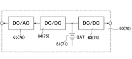
- the auxiliary battery unit 70 includes, for example, a battery 71 made of a Li ion battery, an AC / DC converter 72 that converts AC power obtained by the wind power generator, as shown in FIG. A DC / DC converter 73 that charges the battery 71 by converting the output voltage of the DC converter 72 is provided. Further, the auxiliary battery unit 70 includes a DC / DC converter 74 that converts the DC power stored in the battery 71 into the DC voltage (DC12V) and outputs the same. The auxiliary battery unit 70 is also housed in a housing having the same dimensions as the power supply unit 20.
- assistant battery unit 60,70 and the said wind power generation device it is clearly different from the alternating current power supply line 42 mentioned above, for example of each said auxiliary
- each of the auxiliary battery units 60 and 70 has a DC / DC converter 64 (75) for converting DC power stored in the battery 61 (71) by voltage conversion, and this DC.
- a DC / AC converter 65 (76) for generating the AC power (AC 200V) from the output of the / DC converter 64 (75) is provided. It is also useful to configure so that the output (AC 200 V) of the DC / AC converter 65 (76) can be fed to the AC power supply line 42.
- the battery unit 30 is connected with the DC power stored in the batteries 61 and 71 of the auxiliary battery units 60 and 70, respectively.
- the power supply performance of the power supply unit 20 can be effectively backed up.
- a part of direct current power (DC 12 V) fed from the power supply unit 20 to the server 4 can be supplemented with power that can be output from the auxiliary battery units 60 and 70. Therefore, the load applied to the power supply unit 20 can be reduced.
- control units 26 and 36 mounted on the power supply unit 20 and the battery unit 30 and their control functions will be described. These control units 26 and 36 basically serve to control operations of the power supply circuit unit 21 and the battery circuit unit 31.
- the control units 26 and 36 control the fan drive units 27 and 37, respectively, to control the rotation speeds (air volumes) of the fan devices 28 and 38 provided in the housings of the power supply unit 20 and the battery unit 30, respectively. It also has a function to control.
- the fan devices 28 and 38 allow air to flow inside the respective casings and release heat generated by the power supply circuit unit 21 and the battery circuit unit 31 to the outside of the casings.
- the fan devices 28 and 38 serve to prevent overheating (high temperature) of the power supply circuit unit 21 and the battery circuit unit 31 due to the heat release.
- the fan devices 28 and 38 are generally provided at the back of the casing, and release the heat inside the casing by blowing air toward the back side of the server rack 40.
- the unbalance compensation control function 51 uses the R-phase, S-phase, and T-phase power amounts from the R phase, S phase, and T phase in the above-described three-phase AC input uninterruptible power supply 10. Monitor for imbalances.
- the unbalance compensation control function 51 uses the charge / discharge power of each battery 32 in the battery unit 30 of each phase to control the amount of power output from the power supply unit 20 of each phase, thereby Compensates for unbalance between the phases.
- the backup control function 52 generally indicates that the operating state (output current) of the power supply unit 20 is equal to or lower than the rated power of the power supply unit 20, and the storage state (charge capacity) in the battery unit 30 is fully charged. It is activated when less than In this case, the backup control function 52 determines, for example, the difference between the rated current of the power supply unit 20 and the output current amount of the power supply unit 20 as the surplus current amount that the power supply unit 20 can further output, that is, the surplus power amount. Asking. The backup control function 52 charges the battery 32 of the battery unit 30 using the surplus power and stores DC power in the battery 32. The battery 32 is charged until the battery 32 is fully charged. This charge control is particularly effective when power energy from the above-described solar power generation device or wind power generation device cannot be obtained.
- the conversion efficiency control function 53 plays a role of increasing the conversion efficiency in the power supply unit 20 by controlling the charge / discharge of the battery 32.
- This conversion efficiency control is executed, for example, by obtaining a ratio (load ratio; X% load) to the maximum load from the amount of output current of the power supply unit 20.
- the difference of the load ratio for example, 30% load
- the charging / discharging of the battery unit 30 is controlled by the difference so that the load ratio of the power supply unit 20 is 30%, thereby adjusting the amount of current output from the power supply unit 20.
- a load current amount required for the power supply unit 20 corresponds to a 50% load
- a current corresponding to a 20% load that is a difference from the 30% load is supplied from the battery unit 30.
- the power supply unit 20 outputs only a 30% load current, so that the operation of the power supply unit 20 is brought into a 30% load state.
- the load current amount required for the power supply unit 20 corresponds to a 25% load
- an extra current corresponding to a 5% load which is a difference from the 30% load, is taken out from the power supply unit 20.
- the current of the 5% load is used for charging the battery unit 30 to set the operation of the power supply unit 20 to the 30% load state.
- the operation of the power supply unit 20 is set to a 30% load state, and the conversion efficiency ⁇ is increased to increase the efficiency of the entire uninterruptible power supply 10.
- the overload control function 54 performs the overload operation of the power supply unit 20 when the load of the server 4 temporarily becomes heavy and the load current output from the power supply unit 20 exceeds the rated current. Play a role to suppress.
- the overload control function 54 is executed when the amount of load current supplied to the server 4 side exceeds the rated current of the power supply unit 20. Then, the overload control function 54 obtains the difference between the load current and the rated current as an amount of current that is insufficient for the server 4, and the current corresponding to the amount of insufficient current is obtained from the battery unit 30. The operation of the battery unit 30 is controlled.
- the server 4 is supplied with both the current output from the power supply unit 20 and the current output from the battery unit 30.
- the current (load current amount) output from the power supply unit 20 can be suppressed to the rated current.
- the amount of load current required for the power supply unit 20 that exceeds the rated current is supplemented by the current from the battery unit 30.
- the power failure control function 55 is a case where a plurality of uninterruptible power supply devices 10 are controlled in parallel under the management of the management unit 15, and the high-voltage AC power (AC 400V) from the system power source. Executed when the supply of is cut off. Specifically, at the time of a power failure, each of the uninterruptible power supply devices 10 basically switches the power supply to the server 4 that each of the uninterruptible power supply devices 10 is supplied to from the battery unit 30. At this time, the power failure control function 55 determines the amount of power stored in each battery unit 30 of the plurality of uninterruptible power supply devices 10 and the amount of current to be supplied to the server 4 from each battery unit 30. The backup possible time during which power can be supplied to the server 4 is obtained.
- auxiliary battery units 60 and 70 are provided and AC power (AC200V / AC400V) is output from the auxiliary battery units 60 and 70 to the AC power supply line 42, the following is performed.
- the power supply unit 20 can be prevented from shifting to the complete power failure mode.
- the auxiliary battery unit can be secured to a certain extent from the AC power supply line 42 for the operation of the uninterruptible power supply 10.
- DC power stored in 60 and 70 is converted into AC voltage and output to the AC power (AC200V / AC400V) feed line.
- the fan control function 56 plays a role of driving the fan devices 28 and 38 even when the power supply unit 20 and / or the battery unit 30 has stopped its operation.
- the fan devices 28 and 38 form an air flow inside the housing containing the power supply unit 20 and the battery unit 30 and discharge heat generated inside the housing to the outside.
- the fan devices 28 and 38 serve to cool the entire uninterruptible power supply 10 by discharging the heat in the server rack 40 to the outside.
- the fan control function 56 prevents the stagnation of the air flow in the server rack 40 by driving the fan devices 28 and 38 having such a role, thereby causing local overheating in the server rack 40. Is preventing.
- the fan control function 56 collects not only the load status of each uninterruptible power supply 10 but also the load status of the server 4.
- the rotational speeds of the fan devices 28 and 38 are individually controlled according to these load conditions, thereby forming a smooth air flow in the server rack 40.
- the collection of the load status is performed by information communication between the power supply unit 20 and the battery unit 30 constituting the uninterruptible power supply 10, further the auxiliary battery units 60 and 70, and the server 4. Is called.
- the storage location in the server rack 40 is determined by, for example, the mounting position identification provided in each of the units 20, 30, 60, and 70. It may be preset in advance using the DIP switch.
- the power supply unit 20 when the power supply unit 20 shifts to the complete power failure mode due to the power failure of the AC power (AC200V / AC400V), power can be supplied from the battery unit 30 to the server 4. it can.
- the operation (operation) of the server 4 can be continued even during the power failure. Therefore, for example, if the power supply unit 20 is removed from the server rack 40, the operation of the power supply unit 20 can be forcibly stopped. That is, the power supply unit 20 can be set to the complete stop mode in a pseudo manner.
- DC power (DC 12 V) is supplied from the battery unit 30 connected in parallel to the power supply unit 20 to the server 4. Therefore, if the discharge characteristic of the battery 32 in the battery unit 30 at this time, specifically, the change in the charging voltage of the battery 32 with the passage of time is measured, the degree of characteristic deterioration of the battery 32 from the measured discharge characteristic. Can be easily diagnosed.
- the output of the power supply unit 20 is forcibly set to zero [0] or reduced.
- the discharge characteristic of the said battery 32 in the said battery unit 30 at that time specifically, the change of the charging voltage of the said battery 32 with time passage are measured.
- the degree of characteristic deterioration of the battery 32 can be diagnosed from the measured discharge characteristics of the battery 32. In this way, deterioration diagnosis of the battery 32 can be performed without forcibly generating a power failure state by artificially disconnecting the input or output of the power supply unit 20 from the server rack 40 or removing the power supply unit 20. Can be performed.
- the battery remains in a state where the power supply system 100 is operated without causing a pseudo power failure of the AC power (AC200V / AC400V).
- the deterioration diagnosis of the battery 32 provided in the unit 30 can be easily executed.
- the deterioration diagnosis of the battery 32 can be individually performed for each battery unit 30 in the plurality of uninterruptible power supply apparatuses 10. Therefore, in operating this power supply system 100, the AC power (AC200V / AC400V) does not need to be artificially interrupted, so that the maintenance can be carried out easily, efficiently and safely. The effect of becoming.
- the uninterruptible power supply 10 it is possible to achieve stable operation including the above-mentioned incidental control functions. Furthermore, as described above, the power supply system 100 with high expandability can be easily configured, and there are significant effects in practical use such as low cost. Furthermore, since the power supply unit 20 and the battery unit 30 can be housed and configured in a small casing that can be mounted on the server rack 40, the handling is easy. Since it can be easily attached and detached, the effects such as easy maintenance can be achieved.
Landscapes
- Engineering & Computer Science (AREA)
- Power Engineering (AREA)
- Business, Economics & Management (AREA)
- Emergency Management (AREA)
- Stand-By Power Supply Arrangements (AREA)
- Power Sources (AREA)
- Charge And Discharge Circuits For Batteries Or The Like (AREA)
Abstract
The present invention is provided with: a power source unit (20) in which is accommodated, in a housing of prescribed dimensions, a power source circuit part (21) for converting alternating-current power and generating direct-current voltage to be supplied to a load device (4); a battery unit (30) provided in alignment with the power source unit, the battery unit (30) accommodating, in a housing of the same dimensions as the power source unit, a battery circuit part (31) for storing direct-current power and discharging the stored direct-current power to generate direct-current voltage to be supplied to the load device; and a rack (40) in which the power source unit and the battery unit are each removably mounted, the rack (40) connecting in parallel the power source circuit part of the power source unit and the battery circuit part of the battery unit.
Description
本発明は、例えばデータセンターに設備されて、マルチノードサーバを構成する複数台のサーバ(負荷機器)に電力を供給する電源システムを省スペースで構築することのできる無停電電源装置に関する。
The present invention relates to an uninterruptible power supply apparatus that can be constructed in a space-saving manner, for example, in a power supply system that is installed in a data center and supplies power to a plurality of servers (load devices) that constitute a multi-node server.
図12は、直流電圧を駆動電源とする複数台の負荷機器、例えば複数のサーバを備えたデータセンターにおける従来一般的な電源システムの概略構成図である。この電源システムは、400V系の系統電源に介装された無停電電源装置(UPS)1と、この無停電電源装置1を介して給電される高電圧交流電力(AC400V)を、例えば200V系または100V系の交流電力に変換する交流用の電源分配器(PDU)2とを備える。
FIG. 12 is a schematic configuration diagram of a conventional general power supply system in a data center including a plurality of load devices using a DC voltage as a driving power source, for example, a plurality of servers. This power supply system includes an uninterruptible power supply (UPS) 1 interposed in a 400V system power supply and high-voltage AC power (AC400V) fed via the uninterruptible power supply 1, for example, 200V or And an AC power supply distributor (PDU) 2 for converting into 100V AC power.
ちなみに前記無停電電源装置1は、基本的には直流電力を蓄電可能な大容量のバッテリ(BAT)1aを備える。また前記無停電電源装置1は、前記高電圧交流電力を直流電圧に変換して前記バッテリ1aを充電するAC/DC変換器1bと、このAC/DC変換器1bの出力電圧、または前記バッテリ1aに蓄電された直流電力を高電圧交流電力に変換して出力するDC/AC変換器1cとを備えて構成される。
Incidentally, the uninterruptible power supply 1 basically includes a large capacity battery (BAT) 1a capable of storing DC power. The uninterruptible power supply 1 includes an AC / DC converter 1b that converts the high-voltage AC power into a DC voltage to charge the battery 1a, an output voltage of the AC / DC converter 1b, or the battery 1a. And a DC / AC converter 1c that converts the DC power stored in the battery into high-voltage AC power and outputs it.
ここで前記電源分配器2は、例えば前記系統電源と前記負荷機器(サーバ)を備えた負荷設備側とを切り離す遮断器2aを備える。また前記交流用の電源分配器2は、更に前記高電圧交流電力(AC400V)を、例えば200V系の交流電力に変換して出力するトランス2bを備える。尚、図中3は、例えば6.6kVの送電交流電力を前記高電圧交流電力(AC400V)に変換して前記無停電電源装置1等が設けられた建物内に引き込むトランスである。
Here, the power distribution unit 2 includes a circuit breaker 2a that separates, for example, the system power supply and the load facility side including the load device (server). The AC power supply distributor 2 further includes a transformer 2b that converts the high-voltage AC power (AC 400V) into, for example, 200V AC power and outputs it. In the figure, reference numeral 3 denotes a transformer which converts, for example, 6.6 kV transmission AC power into the high-voltage AC power (AC 400 V) and draws it into the building where the uninterruptible power supply 1 and the like are provided.
また前記負荷機器としての複数台のサーバ4を備えて構築される負荷設備は、その前段部に前記電源分配器2に接続されて前記交流電力(AC200V)から前記サーバ4の駆動電源電圧である48V以下の低電圧直流電力(例えばDC12V)を生成するスイッチング電源5を備える。このスイッチング電源5は、一般的には前記交流電力(AC200V)を直流電圧に変換するAC/DC変換器5aと、このAC/DC変換器5aの出力電圧を前記サーバ4に給電する直流出力電圧(DC12V)に変換するDC/DC変換器5bとを備える。そして前記複数台のサーバ4は前記スイッチング電源5にそれぞれ接続され、該スイッチング電源5から当該サーバ4の駆動電源である前記直流出力電圧が給電されて動作する(例えば特許文献1を参照)。
Further, the load equipment constructed by including a plurality of servers 4 as the load devices is connected to the power supply distributor 2 at the front stage thereof, and is the drive power supply voltage of the server 4 from the AC power (AC200V). A switching power supply 5 that generates low-voltage direct current power (for example, DC12V) of 48V or less is provided. The switching power supply 5 generally includes an AC / DC converter 5a that converts the AC power (AC 200V) into a DC voltage, and a DC output voltage that supplies the output voltage of the AC / DC converter 5a to the server 4. And a DC / DC converter 5b for conversion to (DC12V). The plurality of servers 4 are respectively connected to the switching power supply 5 and are operated by being supplied with the DC output voltage, which is a driving power supply for the server 4, from the switching power supply 5 (see, for example, Patent Document 1).
尚、前記複数台のサーバ4は、一般的には所定数ずつサーバラックに収納されてサーバ群を形成して設備され、前記スイッチング電源装置5は各サーバ群のそれぞれに対応して設けられる。そして前記スイッチング電源装置5は、前記所定数のサーバ4と共に前記サーバラックに一体に収納される。これらの複数台のサーバ4は、いわゆるマルチノードサーバを構築する。
The plurality of servers 4 are generally installed in a server rack by storing a predetermined number of servers 4 so as to form a server group, and the switching power supply 5 is provided corresponding to each server group. The switching power supply 5 is housed in the server rack together with the predetermined number of servers 4. These plural servers 4 construct a so-called multi-node server.
しかしながら上述した如く構成される従来一般的な電源システムは、前述したAC/DC変換器1b,5aやDC/DC変換器5b等の変換段数が多く、電力に対する変換効率が悪い。そこで図13および図14にそれぞれに示すような直流給電系を構築した電源システムが提唱されている。
However, the conventional general power supply system configured as described above has a large number of conversion stages such as the AC / DC converters 1b and 5a and the DC / DC converter 5b described above, and conversion efficiency with respect to power is poor. Therefore, a power supply system in which a DC power supply system as shown in FIGS. 13 and 14 is constructed has been proposed.
図13に示す電源システムは、無停電電源装置1のAC/DC変換器1bから得られる高電圧直流電力(DC400V)を直接的に直流用の電源分配器2に給電する。そして負荷機器側においては、前記電源分配器2aを介して給電される前記高電圧直流電力をDC/DC変換器5dからなるスイッチング電源5に入力し、該スイッチング電源5(DC/DC変換器5d)にて前記各サーバ4に給電する直流出力電圧(DC12V)を生成するように構成される。この種の電源システムは、例えば高電圧直流給電システム(HVCD)と称される(例えば非特許文献1を参照)。
The power supply system shown in FIG. 13 directly feeds the high-voltage DC power (DC 400V) obtained from the AC / DC converter 1b of the uninterruptible power supply 1 to the DC power supply distributor 2. On the load device side, the high-voltage direct current power fed through the power distributor 2a is input to a switching power source 5 including a DC / DC converter 5d, and the switching power source 5 (DC / DC converter 5d) is input. ) To generate a DC output voltage (DC 12 V) for supplying power to each server 4. This type of power supply system is called, for example, a high-voltage DC power supply system (HVCD) (see, for example, Non-Patent Document 1).
また図14に示す電源システムは、無停電電源装置1のAC/DC変換器1bから得られる高電圧直流電力(DC400V)を、該無停電電源装置1に設けられたDC/DC変換器1dを介して低電圧の直流電圧(DC48V)に変換して前記直流用の電源分配器2aに給電する。そして負荷機器側においては、前記電源分配器2aから給電される直流低電圧をDC/DC変換器5eからなるスイッチング電源5に入力し、該スイッチング電源5(DC/DC変換器5e)にて前記各サーバ4に給電する直流出力電圧(DC12V)を生成するように構成される。この種の電源システムは、例えば低電圧の直流給電システムと称される(例えば非特許文献2を参照)。
Further, the power supply system shown in FIG. 14 uses high voltage direct current power (DC400V) obtained from the AC / DC converter 1b of the uninterruptible power supply 1 as a DC / DC converter 1d provided in the uninterruptible power supply 1. Then, the power is converted to a low DC voltage (DC48V) and supplied to the DC power supply distributor 2a. On the load device side, the DC low voltage fed from the power supply distributor 2a is input to the switching power supply 5 including the DC / DC converter 5e, and the switching power supply 5 (DC / DC converter 5e) The server 4 is configured to generate a DC output voltage (DC 12 V) that supplies power to each server 4. This type of power supply system is called, for example, a low-voltage DC power supply system (see, for example, Non-Patent Document 2).
尚、上述した電源システムにおける無停電電源装置1に関する技術として、例えば特許文献2には無停電電源装置を並列運転することが開示されている。また特許文献3には無停電電源装置の並列運転数を増加させた際、スイッチを切り替えることでバッテリだけを並列接続し、これによってバッテリ容量を変更することが開示されている。
As a technique related to the uninterruptible power supply 1 in the above-described power supply system, for example, Patent Document 2 discloses that the uninterruptible power supply is operated in parallel. Further, Patent Document 3 discloses that when the number of parallel operations of the uninterruptible power supply apparatus is increased, only the batteries are connected in parallel by switching the switch, thereby changing the battery capacity.
しかしながら図13に示す高電圧直流給電システムにおいては、前記電源分配器2における遮断器2aとして高電圧直流電力を遮断する上で大型のものが必要である。即ち、一般的には機械式接点の遮断器による直流の高電圧・大電流の遮断は困難であり、同じ定格の交流の電圧・電流を遮断する機械式接点の遮断器に比較して前記遮断器2aが大幅に大型化する。これ故、設備コスト増大の要因となる。その上、メンテナンス頻度の高い前記サーバラック内に前記高電圧直流電力を引き込むためには、その直流電圧(DC400V)に対する感電対策も必要となる。
However, in the high-voltage DC power supply system shown in FIG. 13, a large-sized device is necessary as the circuit breaker 2 a in the power supply distributor 2 in order to cut off the high-voltage DC power. That is, in general, it is difficult to cut off the high voltage / current of direct current using a mechanical contact breaker. Compared to a mechanical contact breaker that cuts off AC voltage / current of the same rating, The vessel 2a is greatly increased in size. Therefore, it becomes a factor of equipment cost increase. In addition, in order to draw the high-voltage DC power into the server rack having a high maintenance frequency, it is necessary to take an electric shock countermeasure against the DC voltage (DC 400 V).
この点、図14に示す直流給電システムにおいては、前記サーバラック内に引き込む直流電力の電圧がDC48Vと低いので、該直流電圧(48V)に対する感電の影響は少ない。しかしこの直流給電システムでは低電圧の直流大電流を取り扱うので、配電線等の導体における損失や発熱を低減する為の配慮が必要である。更には前述した遮断器2aについても大電流に対応し得る大型のものが必要となる。この為、その設備コストの増大を招来することが否めない。
In this respect, in the DC power supply system shown in FIG. 14, since the voltage of the DC power drawn into the server rack is as low as DC48V, there is little influence of electric shock on the DC voltage (48V). However, since this direct current power supply system handles a large direct current of low voltage, it is necessary to consider for reducing loss and heat generation in conductors such as distribution lines. Furthermore, the circuit breaker 2a described above is also required to have a large size that can handle a large current. For this reason, it cannot be denied that the equipment cost increases.
また前記データセンターにおいては、通常、数百kW以上の大容量で大型の無停電電源装置1を集中配置し、前述したように系統電源に介装している。この為、前記データセンターにおける前記無停電電源装置1の設置に要するスペースが大きな割合を占める。しかも前記無停電電源装置1に不具合が生じた際の影響が前記全てのサーバ(負荷装置)4に普及することが否めず、信頼性低下の要因ともなっている。また前述した特許文献2,3にそれぞれ開示される技術では、バッテリを並列接続してその容量を増設するには複数の無停電電源装置を並列に用いることが必要であり、そのシステム構成が大掛かりになると言う不具合がある。
In the data center, large uninterruptible power supply units 1 having a large capacity of several hundred kW or more are generally arranged in a concentrated manner, and are interposed in the system power supply as described above. For this reason, the space required for installation of the uninterruptible power supply 1 in the data center occupies a large proportion. Moreover, it is unavoidable that the influence when a failure occurs in the uninterruptible power supply 1 spreads to all the servers (load devices) 4, which also causes a decrease in reliability. Further, in the technologies disclosed in Patent Documents 2 and 3 described above, it is necessary to use a plurality of uninterruptible power supplies in parallel in order to increase the capacity by connecting batteries in parallel, and the system configuration is large. There is a problem to say.
本発明はこのような事情を考慮してなされたもので、その目的は、例えば複数台のサーバからなる負荷機器に電力を供給する電源システムを省スペースでコンパクトに、しかも要求される電力容量に応じて簡易に構築することのできる無停電電源装置を提供することにある。
The present invention has been made in consideration of such circumstances, and an object of the present invention is, for example, to provide a power supply system that supplies power to a load device composed of a plurality of servers in a compact and space-saving manner, and to achieve a required power capacity. An object of the present invention is to provide an uninterruptible power supply that can be easily constructed in response.
上述した目的を達成するべく本発明に係る無停電電源装置は、
交流電力を変換して負荷機器に給電する直流電圧を生成する電源回路部を所定寸法の筐体に収納した電源ユニットと、
この電源ユニットに並べて設けられて直流電力を蓄電すると共に、蓄電した直流電力を放電させて前記負荷機器に給電する直流電圧を生成するバッテリ回路部を前記電源ユニットと同一寸法の筐体に収納したバッテリユニットと、
前記電源ユニットと前記バッテリユニットとをそれぞれ着脱自在に装着して該電源ユニットの電源回路部と前記バッテリユニットとのバッテリ回路部とを並列接続するラックと
を具備したことを特徴としている。 The uninterruptible power supply according to the present invention to achieve the above-described object is
A power supply unit that houses a power supply circuit unit that converts alternating current power and generates a direct current voltage for supplying power to a load device in a casing of a predetermined size;
A battery circuit unit that is provided side by side in the power supply unit and stores DC power, and generates a DC voltage that discharges the stored DC power and supplies power to the load device is housed in a casing having the same dimensions as the power supply unit. A battery unit;
The power supply unit and the battery unit are detachably mounted, and a rack for connecting the power supply circuit portion of the power supply unit and the battery circuit portion of the battery unit in parallel is provided.
好ましくは前記ラックは、該ラックの前面側から前記電源ユニットおよび前記バッテリユニットとをそれぞれ着脱自在に装着すると共に、該ラックの裏面側において前記電源ユニットおよび前記バッテリユニットの各筐体にそれぞれ設けられたコネクタを介して前記電源回路部および前記回路部に結合されて前記電源ユニットと前記バッテリユニットとを並列に接続する接続構造体を備えて構成される。
Preferably, the rack is detachably attached to the power supply unit and the battery unit from the front side of the rack, and is provided in each housing of the power supply unit and the battery unit on the back side of the rack. The power supply circuit unit is connected to the circuit unit via a connector, and the connection unit is connected to the power supply unit and the battery unit in parallel.
ちなみに前記接続構造体は、系統電源に接続された交流電源ラインと、負荷機器に直流電圧を給電する直流電力ラインとからなる。また前記バッテリユニットは、前記直流電力ラインを介して前記電源ユニットに対して並列接続されるものであって、前記バッテリ回路部は、前記電源ユニットから出力される直流電圧を入力してバッテリに直流電力を蓄電し、該バッテリに蓄電した直流電力から前記負荷機器に給電する直流電圧を生成するDC/DC変換器を備えて構成される。
Incidentally, the connection structure is composed of an AC power supply line connected to the system power supply and a DC power line for supplying a DC voltage to the load device. The battery unit is connected in parallel to the power supply unit via the DC power line, and the battery circuit unit inputs a DC voltage output from the power supply unit and outputs the DC to the battery. It comprises a DC / DC converter that stores electric power and generates a DC voltage for supplying power to the load device from DC power stored in the battery.
好ましくは前記コネクタは、前記ラックへの前記電源ユニットまたは前記バッテリユニットの装着に伴って連結されると共に、前記電源ユニットまたは前記バッテリユニットの前記ラックからの取り外しに伴って連結解除されるプラグイン型の対をなす接栓および接栓座の一方からなり、また前記接続構造体は、前記接栓および接栓座の他方を備えて構成される。
Preferably, the connector is connected to the rack when the power supply unit or the battery unit is attached to the rack, and is disconnected when the power supply unit or the battery unit is removed from the rack. And the connection structure is configured to include the other one of the plug and the plug seat.
更に好ましくは前記接続構造体を、前記電源ユニットまたは前記バッテリユニットが選択的に装着される前記ラックの複数の収納領域に跨って設ける。また前記接続構造体に、隣接する前記収納領域間で前記直流電力ラインを切り離した端子部を設け、この端子部に装着される端子ユニットを介して前記直流電力ラインを並列接続または直列接続する連結構造として実現することが望ましい。
More preferably, the connection structure is provided across a plurality of storage areas of the rack on which the power supply unit or the battery unit is selectively mounted. In addition, the connection structure is provided with a terminal portion in which the DC power line is separated between the adjacent storage areas, and the DC power line is connected in parallel or in series via a terminal unit attached to the terminal portion. It is desirable to realize as a structure.
尚、前記バッテリ回路部に、前記バッテリに蓄電した直流電力から前記電源ユニットら給電する交流電力を生成して前記交流電源ラインに出力するDC/AC変換器を設けることも好適である。更に前記バッテリ回路部に、前記交流電源ラインとは別に設けられた電源入力系に接続され、該電源入力系を介して太陽光発電装置または風力発電装置から得られる電力を電圧変換して前記バッテリに蓄電する変換器を設けることも望ましい。
It is preferable that the battery circuit unit is provided with a DC / AC converter that generates AC power supplied from the power supply unit from DC power stored in the battery and outputs the AC power to the AC power supply line. Further, the battery circuit unit is connected to a power supply input system provided separately from the AC power supply line, and the battery is configured to convert the power obtained from the solar power generation device or the wind power generation device via the power supply input system to the voltage. It is also desirable to provide a converter for storing electricity.
好ましくは前記ラックは、例えば複数台の負荷機器を縦並びに装着可能なEIA規格に準拠した寸法を有するとき、前記電源ユニットおよび前記バッテリユニットをそれぞれ個別に収納した前記所定寸法の筐体を、前記ラックの基本収納サイズ、またはこの基本収納サイズを幅方向にN等分(Nは2以上の自然数)した分割サイズを有するものとして実現する。そして前記電源ユニットおよび前記バッテリユニットを、所定数の負荷機器と共に前記ラックに装着することが望ましい。
Preferably, when the rack has a size conforming to the EIA standard in which, for example, a plurality of load devices can be mounted vertically, the casing of the predetermined size in which the power supply unit and the battery unit are individually stored, The basic storage size of the rack or the division size obtained by dividing this basic storage size into N equal parts (N is a natural number of 2 or more) in the width direction is realized. It is desirable that the power supply unit and the battery unit are mounted on the rack together with a predetermined number of load devices.
尚、前記電源ユニットは、三相交流電源の各相に対してそれぞれ個別に設けられる。また前記バッテリユニットは、1台の電源ユニットに対して複数台並列に設けるようにしても良い。
The power supply unit is individually provided for each phase of the three-phase AC power supply. A plurality of the battery units may be provided in parallel with respect to one power supply unit.
また前記電源ユニットおよび前記バッテリユニットのそれぞれに、前記各筐体の内部に空気を通流させて前記電源回路部および前記バッテリ回路部における熱を放出させるファン装置を設け、これらの各ファン装置を、前記電源回路部および前記バッテリ回路部の動作停止時においても駆動することが望ましい。
Each of the power supply unit and the battery unit is provided with a fan device that causes air to flow inside the housings to release heat in the power supply circuit unit and the battery circuit unit. It is desirable that the power supply circuit unit and the battery circuit unit are driven even when operation is stopped.
上述した構成の無停電電源装置によれば、電源ユニットとバッテリユニットとを個別に構成し、これらの電源ユニットおよびバッテリユニットをそれぞれラックに収納して電源回路部とバッテリ回路部とを並列に接続するだけなので拡張性に富み、負荷の仕様に応じた電源システムを容易に構築することができる。しかも電源ユニットに並列接続するバッテリユニットを容易に増設して、その電力容量を高めることも容易である。
According to the uninterruptible power supply having the configuration described above, the power supply unit and the battery unit are configured separately, and the power supply unit and the battery circuit unit are connected in parallel by storing these power supply units and the battery unit in a rack, respectively. Therefore, the power supply system can be easily built according to the load specifications. Moreover, it is easy to increase the power capacity by easily adding battery units connected in parallel to the power supply unit.
また無停電電源装置を構成する前記電源ユニットとバッテリユニットとを、例えば複数台の負荷装置(サーバ)を収納するラックの空きスペースを利用して設備することが可能である。従って大容量の無停電電源装置を系統電源に集中配置する従来の電源システムのように、データセンターに前記無停電電源装置を設置する為の専用スペースを確保する必要がなく、コンパクトに電源システムを構築することができる。更には前記電源回路部および前記バッテリ回路部をそれぞれ個別に同一寸法の筐体に収納して前記電源ユニットおよび前記バッテリユニットをそれぞれ構成するので、前記電源ユニットおよび前記バッテリユニットをそれぞれ所定の、電力容量を有するユニットとして安価に構築することができる。従って無停電電源装置としても、全体的に安価に構築することが可能となる。
Also, it is possible to install the power supply unit and the battery unit constituting the uninterruptible power supply using, for example, an empty space of a rack that stores a plurality of load devices (servers). Therefore, there is no need to secure a dedicated space for installing the uninterruptible power supply in the data center unlike the conventional power supply system in which a large-capacity uninterruptible power supply is centrally arranged in the system power supply. Can be built. Further, the power supply circuit unit and the battery circuit unit are individually housed in a casing having the same dimensions to constitute the power supply unit and the battery unit, respectively. It can be constructed at a low cost as a unit having a capacity. Therefore, it is possible to construct the uninterruptible power supply apparatus at a low cost as a whole.
また複数の無停電電源装置間において、例えば負荷状況に応じて前記バッテリユニットを運用して前記電源ユニットの変換効率を高めたり、前記交流電力量の低下を補償すること等も可能となる。更には前記電源ユニットおよび前記バッテリユニットを個々に交換したり、また個々にメンテンスすることも可能となるので、その保守管理が簡単である等の利点もある。故に本発明によれば電源システム全体の高効率化と省スペース化を図ると共に、その設備コストを抑えることができる等の効果を奏し得る無停電電源装置を提供することができる。
In addition, among the plurality of uninterruptible power supply apparatuses, for example, the battery unit can be operated according to the load condition to increase the conversion efficiency of the power supply unit, or to compensate for the decrease in the AC power amount. Furthermore, since the power supply unit and the battery unit can be individually replaced or individually maintained, there is an advantage that the maintenance management is simple. Therefore, according to the present invention, it is possible to provide an uninterruptible power supply that can achieve the effects of, for example, improving the efficiency and space saving of the entire power supply system and suppressing the equipment cost.
以下、図面を参照して本発明の実施形態に係る無停電電源装置について説明する。
Hereinafter, an uninterruptible power supply according to an embodiment of the present invention will be described with reference to the drawings.
図1は実施形態に係る無停電電源装置を用いて構築される電源システム100の概略構成図である。この電源システム100は、例えばデータセンターに設けられてマルチノードサーバを構築する複数台のサーバ(負荷機器)4のそれぞれに、該サーバ4の駆動源である12Vの直流電圧を供給するに好適なものである。尚、図1においては従来の電源システムと同一部分には同一符号を付して示してある。
FIG. 1 is a schematic configuration diagram of a power supply system 100 constructed using the uninterruptible power supply according to the embodiment. The power supply system 100 is suitable for supplying a DC voltage of 12V, which is a drive source of the server 4, to each of a plurality of servers (load devices) 4 provided in a data center and constructing a multi-node server, for example. Is. In FIG. 1, the same parts as those of the conventional power supply system are denoted by the same reference numerals.
この電源システム100は、400V系の系統電源に接続された交流用の電源分配器(PDU)2を備え、この電源分配器2を介して前記サーバ(負荷機器)4を複数台収納したサーバラック40に前記交流電力を給電するように構成される。この図1に示す電源システム100は、前記電源分配器2にトランス2bを内蔵し、前記系統電源から給電される高電圧交流電力(AC400V)を200Vの交流電力に変換して負荷側(サーバラック40)に給電するように構成される。尚、前記交流電力(AC400V)をそのまま前記電源分配器2を介して負荷側に給電するように構成することも勿論可能である。
The power supply system 100 includes an AC power supply distributor (PDU) 2 connected to a 400 V system power supply, and a server rack that houses a plurality of the servers (load devices) 4 via the power supply distributor 2. The AC power is supplied to 40. The power supply system 100 shown in FIG. 1 includes a transformer 2b in the power supply distributor 2, converts high-voltage AC power (AC400V) fed from the system power supply into 200V AC power, and converts it to the load side (server rack). 40). Of course, the AC power (AC 400V) may be supplied to the load side via the power distributor 2 as it is.
ここで前記サーバ(負荷機器)4を複数台収納した前記サーバラック40には、所定数のサーバ4からなるサーバ群のそれぞれに対応して、電源ユニット20とバッテリユニット30とにより構成される無停電電源装置10が設けられる。前記電源ユニット20は、その本体をなす電源回路部21を、前記サーバラック40に装着可能な所定寸法の筐体に収納して構成される。
Here, in the server rack 40 in which a plurality of the servers (load devices) 4 are accommodated, there is no power supply unit 20 and a battery unit 30 corresponding to each of a server group including a predetermined number of servers 4. A power failure power supply 10 is provided. The power supply unit 20 is configured by storing a power supply circuit unit 21 constituting a main body thereof in a casing of a predetermined size that can be mounted on the server rack 40.
ちなみに前記電源回路部21は、前記交流電力(AC200V/AC400V)を直流電圧に変換するAC/DC変換器22を備える。更に前記電源回路部21は、上記AC/DC変換器22の出力電圧を前記サーバ4に給電する直流電圧(DC12V)に変換するDC/DC変換器23を備える。この電源回路部21は、図12に示した前記スイッチング電源5に相当するものである。従って電源回路部21を構成する前記AC/DC変換器22および前記DC/DC変換器23は、前記スイッチング電源5における前記AC/DC変換器5aおよび前記DC/DC変換器5bのそれぞれに対応する。
Incidentally, the power supply circuit unit 21 includes an AC / DC converter 22 that converts the AC power (AC200V / AC400V) into a DC voltage. Further, the power supply circuit unit 21 includes a DC / DC converter 23 that converts the output voltage of the AC / DC converter 22 into a DC voltage (DC 12 V) that supplies power to the server 4. The power supply circuit unit 21 corresponds to the switching power supply 5 shown in FIG. Accordingly, the AC / DC converter 22 and the DC / DC converter 23 constituting the power supply circuit unit 21 correspond to the AC / DC converter 5a and the DC / DC converter 5b in the switching power supply 5, respectively. .
また前記バッテリユニット30は、その本体をなすバッテリ回路部31を、前記電源ユニット20の筐体と同一寸法の筐体に収納して構成される。このバッテリユニット30は、前記電源ユニット20に並べて設けられて該電源ユニット20に対して並列的に運転される。ちなみに前記バッテリユニット30(バッテリ回路部31)は、前記電源ユニット20(電源回路部21)の動作時に直流電力を蓄電すると共に、蓄電した直流電力を放電させて前記直流電圧(DC12V)の生成に供する役割を担う。従って前記電源ユニット20および前記バッテリユニット30を並列に備えて構築される前記無停電電源装置10は、前述した無停電電源装置1とは異なって、前記サーバ(負荷機器)4に対する電源機能を備えた直流出力型の無停電電源装置を構築する。
Further, the battery unit 30 is configured by housing the battery circuit unit 31 constituting the main body in a casing having the same dimensions as the casing of the power supply unit 20. The battery unit 30 is provided side by side with the power supply unit 20 and is operated in parallel with the power supply unit 20. Incidentally, the battery unit 30 (battery circuit unit 31) stores DC power during operation of the power supply unit 20 (power supply circuit unit 21), and discharges the stored DC power to generate the DC voltage (DC12V). Take a role to serve. Therefore, the uninterruptible power supply 10 constructed by including the power supply unit 20 and the battery unit 30 in parallel has a power supply function for the server (load device) 4 unlike the uninterruptible power supply 1 described above. Construct a DC output type uninterruptible power supply.
ちなみに前記バッテリ回路部31は、直流電力を蓄電可能なLiイオン電池等のバッテリ32を備える。更に前記バッテリ回路部31は、図1に示すように前記DC/DC変換器23の電圧出力端子に接続されて前記バッテリ32を選択的に充放電する双方向DC/DC変換器33を備えて構成される。この場合、前記双方向DC/DC変換器33は、前述した12Vの直流電圧を受けて前記バッテリ32を充電して直流電力を蓄電する。また前記双方向DC/DC変換器33は、前記バッテリ32に蓄電された直流電力から前記サーバ(負荷機器)4に給電する前記12Vの直流電圧を生成して出力する。
Incidentally, the battery circuit unit 31 includes a battery 32 such as a Li ion battery capable of storing DC power. Further, as shown in FIG. 1, the battery circuit unit 31 includes a bidirectional DC / DC converter 33 that is connected to a voltage output terminal of the DC / DC converter 23 and selectively charges and discharges the battery 32. Composed. In this case, the bidirectional DC / DC converter 33 receives the above-mentioned 12V DC voltage and charges the battery 32 to store DC power. Further, the bidirectional DC / DC converter 33 generates and outputs the 12V DC voltage to be supplied to the server (load device) 4 from the DC power stored in the battery 32.
尚、図1にバッテリユニット30Aとして示すように、前記バッテリ回路部31を前記交流電圧(AC200V/AC400V)を直流電圧に変換するAC/DC変換器34を用いて前記バッテリ32を充電するように構成することも可能である。この場合、前記双方向DC/DC変換器33に代えて、前記バッテリ32に蓄電された直流電力から前記サーバ(負荷機器)4に給電する前記12Vの直流電圧を生成するだけの機能を備えたDC/DC変換器35を用いれば十分である。
As shown as a battery unit 30A in FIG. 1, the battery circuit unit 31 is charged with the battery 32 using an AC / DC converter 34 that converts the AC voltage (AC 200V / AC 400V) into a DC voltage. It is also possible to configure. In this case, in place of the bidirectional DC / DC converter 33, a function of merely generating the 12V DC voltage for supplying power to the server (load device) 4 from the DC power stored in the battery 32 is provided. It is sufficient to use a DC / DC converter 35.
前記バッテリ回路部31がいずれの構成を採用するにしろ、前記バッテリユニット30は前記電源ユニット20に対して並列に設けられ、該電源ユニット20と同時に動作可能に設けられる。ここで上記「同時に動作可能」とは、前記電源ユニット20の動作時に前記バッテリ32を充電することを意味するだけでなく、後述するように前記電源ユニット20の動作時に前記バッテリ32に蓄電されている直流電力を放電させて前記直流電圧(DC12V)を生成することも意味する。
Regardless of the configuration of the battery circuit unit 31, the battery unit 30 is provided in parallel to the power supply unit 20 and is operably provided with the power supply unit 20. Here, “being operable at the same time” not only means that the battery 32 is charged when the power supply unit 20 is operated, but also is stored in the battery 32 when the power supply unit 20 is operated, as will be described later. It also means that the DC voltage (DC12V) is generated by discharging the DC power.
ところで前記各AC/DC変換器22,34は、例えば前述したように高電圧交流電力(AC400V)を所定の直流電圧(DC800V)に変換する役割を担う。ちなみに前記各AC/DC変換器22,34を一般的な2レベル電力変換回路を用いて構築した場合、その半導体スイッチング素子(例えばMOS-FETやIGBT等)には、通常、1000V以上の耐圧特性を備えることが要求される。従って前記各AC/DC変換器22,34については、例えば中性点クランプ方式の3レベル電力変換回路を用いて構成することが望ましい。
By the way, the AC / DC converters 22 and 34 play a role of converting high voltage AC power (AC 400V) into a predetermined DC voltage (DC 800V), for example, as described above. Incidentally, when each of the AC / DC converters 22 and 34 is constructed using a general two-level power conversion circuit, the semiconductor switching element (for example, a MOS-FET or IGBT) usually has a withstand voltage characteristic of 1000 V or more. Is required. Therefore, each of the AC / DC converters 22 and 34 is preferably configured using, for example, a neutral point clamp type three-level power conversion circuit.
なお、この種の中性点クランプ方式の3レベル電力変換回路については、例えば特開2012-253981号公報や特開2011-223867号公報等に詳しく紹介される通りである。そして上記中性点クランプ方式の3レベル電力変換回路によれば、前記半導体スイッチング素子に加わる電圧を、その入力電圧の略1/2に抑えることができる。
Incidentally, this type of neutral point clamp type three-level power conversion circuit is introduced in detail in, for example, Japanese Patent Application Laid-Open Nos. 2012-253981 and 2011-223867. According to the neutral-point clamp type three-level power conversion circuit, the voltage applied to the semiconductor switching element can be suppressed to about ½ of the input voltage.
従って耐圧が600V程度の比較的安価で性能の優れた半導体スイッチング素子を用いて前記各AC/DC変換器22,34をそれぞれコンパクトに構築することが可能となる。しかも半導体スイッチング素子での損失を抑えてその電力変換効率自体も高めることができる。これ故、例えば小型で大容量のLiイオン電池等を用いて前記バッテリ32を小型・軽量化し得ることと相俟って、前述したDC/DC変換器23等を含めて前記電源回路部21および前記バッテリ回路部31をそれぞれコンパクトに構成することができる。
Therefore, the AC / DC converters 22 and 34 can be constructed in a compact manner by using relatively inexpensive semiconductor switching elements having a withstand voltage of about 600 V and excellent performance. In addition, the power conversion efficiency itself can be increased by suppressing the loss in the semiconductor switching element. Therefore, in combination with the fact that the battery 32 can be reduced in size and weight using, for example, a small and large-capacity Li ion battery, the power supply circuit unit 21 including the DC / DC converter 23 described above and the like. Each of the battery circuit portions 31 can be configured compactly.
さて上述した如く構成される前記電源ユニット20および前記バッテリユニット30は、例えば図2に示すように複数台のサーバ(負荷機器)4を縦並びに装着可能なEIA規格に準拠した寸法を有するサーバラック40にそれぞれ着脱自在に収納される。ここで前記電源回路部21収納して前記電源ユニット20を構築する筐体は、前記サーバラック40の基本収納サイズであって、特にこの基本収納サイズを幅方向にN等分(Nは2以上の自然数)した分割サイズのものからなる。具体的には前記筐体は、いわゆる1ユニットサイズ(1Uサイズ)を幅方向に4等分した1/4サイズ(ここでは1U4サイズと略記する)のものからなる。また前記バッテリ回路部31を収納して前記バッテリユニット30を構築する筐体もまた、前記電源ユニット20と同じ寸法の1U4サイズのものからなる。
Now, the power supply unit 20 and the battery unit 30 configured as described above are server racks having dimensions conforming to the EIA standard in which a plurality of servers (load devices) 4 can be mounted vertically as shown in FIG. 40 is removably accommodated in each. Here, the housing that houses the power supply circuit unit 21 and constructs the power supply unit 20 has the basic storage size of the server rack 40, and in particular, divides the basic storage size into N equal parts in the width direction (N is 2 or more). (Natural number) of division size. Specifically, the casing is made of a so-called one-unit size (1U size) that is divided into four equal parts in the width direction (here, abbreviated as 1U4 size). The housing that houses the battery circuit unit 31 and constructs the battery unit 30 also has a 1U4 size that is the same size as the power supply unit 20.
そして前記電源ユニット20および前記バッテリユニット30は、図2(a)に前記サーバラック40を正面(前面)側から見た状態、および図2(b)に前記サーバラック40を背面(裏面)側から見た状態をそれぞれ示すように、前記サーバラック40に並べて収納される。特に前記電源ユニット20および前記バッテリユニット30は、前記サーバラック40の前面側から該サーバラック40にそれぞれ着脱自在に装着される。
The power supply unit 20 and the battery unit 30 are shown in FIG. 2A when the server rack 40 is viewed from the front (front) side, and in FIG. Are stored side by side in the server rack 40 as shown in FIG. In particular, the power supply unit 20 and the battery unit 30 are detachably attached to the server rack 40 from the front side of the server rack 40, respectively.
ここで前記サーバラック40の裏面側には、図2(b)に示すように前記電源ユニット20および前記バッテリユニット30を並列に接続する接続構造体41が設けられている。この接続構造体41は、基本的には前記系統電源に接続されて交流電圧(AC200V/AC400V)を給電する交流電源ライン42と、前記サーバ(負荷機器)に直流電圧(DC12V)を給電する直流電力ライン43とを備える。この接続構造体41は、後述するコネクタを介して前記電源ユニット20および前記バッテリユニット30にそれぞれ結合される。
Here, a connection structure 41 for connecting the power supply unit 20 and the battery unit 30 in parallel is provided on the back side of the server rack 40 as shown in FIG. This connection structure 41 is basically connected to the system power supply and supplied with an AC power supply line 42 that supplies an AC voltage (AC200V / AC400V), and a DC voltage that supplies a DC voltage (DC12V) to the server (load device). And a power line 43. The connection structure 41 is coupled to the power supply unit 20 and the battery unit 30 via connectors described later.
ちなみに前記電源ユニット20および前記バッテリユニット30の各筐体の裏面側に設けられるコネクタ44は、プラグイン型の対をなす接栓および接栓座の一方からなる。また前記接続構造体41には、前記接栓および接栓座の他方が設けられる。このプラグイン型の対をなすコネクタ44は、前記サーバラック40への前記電源ユニット20または前記バッテリユニット30の装着に伴って連結されると共に、前記電源ユニット20または前記バッテリユニット30の前記サーバラック40からの取り外しに伴って連結解除される。
Incidentally, the connector 44 provided on the back side of each housing of the power supply unit 20 and the battery unit 30 is composed of one of a plug-in pair and a plug seat. The connection structure 41 is provided with the other of the plug and the plug seat. The plug-in pair of connectors 44 are connected to the server rack 40 when the power supply unit 20 or the battery unit 30 is mounted, and the server rack of the power supply unit 20 or the battery unit 30 is connected. The connection is released along with the removal from 40.
そして前記コネクタ44は、前記電源回路部21および前記バッテリ回路部31を前記交流電源ライン42および直流電力ライン43にそれぞれ接続し、これによって前記電源ユニット20と前記バッテリユニット30とを並列接続する役割を担う。尚、前記バッテリ回路部31が前述したように電源回路部21から出力される直流電圧(DC12V)を入力して前記バッテリ32を充電するように構成される場合には、前記バッテリユニット30に設けられる前記コネクタ44は、前記直流電力ライン43に対してだけ前記バッテリ回路部31を接続する。
The connector 44 serves to connect the power supply circuit unit 21 and the battery circuit unit 31 to the AC power supply line 42 and the DC power line 43, respectively, thereby connecting the power supply unit 20 and the battery unit 30 in parallel. Take on. When the battery circuit unit 31 is configured to charge the battery 32 by inputting the DC voltage (DC 12V) output from the power circuit unit 21 as described above, the battery circuit unit 31 is provided in the battery unit 30. The connector 44 connected connects the battery circuit unit 31 only to the DC power line 43.
尚、図2(a)(b)は、単相の交流電力(AC200V)を入力する場合の例を示しているが、三相交流電力を入力する場合には前記電源ユニット20は、三相交流電源の各相(R,S,T)に対してそれぞれ個別に設けられる。そしてこれらの各電源ユニット20に対して前記バッテリユニット30がそれぞれ設けられる。この場合には、例えば図3(a)(b)に示すように、前記サーバラック40の縦方向に隣接する2列の収納段を用いて、前記各相(R,S,T)に対する前記電源ユニット20および前記バッテリユニット30を、それぞれ横並びにして収納する。
2 (a) and 2 (b) show an example in which single-phase AC power (AC200V) is input. However, when three-phase AC power is input, the power supply unit 20 has three-phase AC power. It is provided individually for each phase (R, S, T) of the AC power supply. The battery unit 30 is provided for each power supply unit 20. In this case, for example, as shown in FIGS. 3 (a) and 3 (b), two rows of storage stages adjacent to each other in the vertical direction of the server rack 40 are used, and the phases for the respective phases (R, S, T). The power supply unit 20 and the battery unit 30 are housed side by side.
この際、前記接続構造体41については、図3(a)(b)に示すように前記サーバラック40の縦方向に並ぶ複数の収納段間に跨って前記交流電源ライン42および前記直流電力ライン43を延在させた構成としておく。この縦方向に延びる前記交流電源ライン42および前記直流電力ライン43については、前記サーバラック40の背面側の側部に設けられる支柱に沿って設ければ十分である。またここでは図示を省略しているが、前記サーバラック40のサーバ(負荷機器)4を収納する他の収納段についても、前記接続構造体41を延在させて設けられることは言うまでもない。そして前記接続構造体41の前記直流電力ライン43を介して前記サーバ(負荷機器)4に対する直流電圧(DC12V)の給電が行われる。
At this time, with respect to the connection structure 41, as shown in FIGS. 3A and 3B, the AC power supply line 42 and the DC power line straddle the plurality of storage stages arranged in the vertical direction of the server rack 40. 43 is extended. It is sufficient that the AC power supply line 42 and the DC power line 43 extending in the vertical direction are provided along a support column provided on the back side of the server rack 40. Further, although not shown here, it goes without saying that the connection structure 41 is also provided to extend to other storage stages for storing the server (load equipment) 4 of the server rack 40. Then, a DC voltage (DC 12 V) is supplied to the server (load device) 4 through the DC power line 43 of the connection structure 41.
ここで無停電電源装置10の拡張形態について簡単に説明する。交流電源が単相入力の場合、前述したように前記電源ユニット20および前記バッテリユニット30がそれぞれ1U4サイズで実現されるので、基本的には2台の前記電源ユニット20と2台の前記バッテリユニット30を用い、図4(a)に示すように前記サーバラック40の1列の収納段に横並びに収納すれば良い。またバッテリ容量を増加する場合には、例えば図4(b)に示すように前記バッテリユニット30を増設し、これを前記電源ユニット20に隣接する収納段に収納すれば良い。更には前記サーバ(負荷機器)4に対する電源容量自体を増加する場合には、例えば図4(c)に示すように前記電源ユニット20と共に前記バッテリユニット30をそれぞれ増設すれば良い。
Here, the expansion form of the uninterruptible power supply 10 will be briefly described. When the AC power supply is a single-phase input, the power supply unit 20 and the battery unit 30 are each realized in a 1U4 size as described above, so basically two power supply units 20 and two battery units are provided. 30 and stored in a row in the storage stage of the server rack 40 side by side as shown in FIG. Further, when increasing the battery capacity, for example, as shown in FIG. 4B, the battery unit 30 may be added and stored in a storage stage adjacent to the power supply unit 20. Furthermore, when the power capacity itself for the server (load device) 4 is increased, for example, the battery unit 30 may be added together with the power unit 20 as shown in FIG.
尚、交流電源が三相入力の場合には、例えば図5(a)に示すように前記バッテリユニット30を増設してバッテリ容量を増加すれば良い。更には図5(b)に示すように前記電源ユニット20と前記バッテリユニット30とをそれぞれ増設して前記サーバ(負荷機器)4に対する電源容量自体を増大することも勿論可能である。この場合、縦並びの3段の収納段のそれぞれに、前記電源ユニット20と前記バッテリユニット30とを並べて収納することが望ましい。
When the AC power supply is a three-phase input, for example, as shown in FIG. 5A, the battery unit 30 may be added to increase the battery capacity. Further, as shown in FIG. 5B, it is of course possible to increase the power supply capacity itself for the server (load device) 4 by adding the power supply unit 20 and the battery unit 30 respectively. In this case, it is desirable to store the power supply unit 20 and the battery unit 30 side by side in each of the three vertical storage stages.
即ち、本無停電電源装置10における前記電源ユニット20および前記バッテリユニット30は同一サイズで、且つ個別に構成されている。従って無停電電源装置10に要求される電力容量に応じて、また交流電源の停電時における前記バッテリユニット30によるバックアップ時間に応じて、前記電源ユニット20および前記バッテリユニット30を適宜増設することができる。故に本無停電電源装置10は、拡張性に富み、種々の仕様に応じた電源システム100を構築することが可能である。
That is, the power supply unit 20 and the battery unit 30 in the uninterruptible power supply 10 are the same size and are individually configured. Accordingly, the power supply unit 20 and the battery unit 30 can be appropriately added according to the power capacity required for the uninterruptible power supply 10 and according to the backup time of the battery unit 30 at the time of a power failure of the AC power supply. . Therefore, this uninterruptible power supply 10 is rich in expandability, and can construct the power supply system 100 according to various specifications.
次に上述した如く前記電源ユニット20および前記バッテリユニット30を収納する前記サーバラック40について説明する。このサーバラック40には、前述したようにその背面に前記接続構造体41が設けられる。図6はこの接続構造体41の概略的な構成例を示すもので、図中、44は前記交流電源ライン42および直流電力ライン43に接続されたコネクタを示している。これらのコネクタ44は、前記サーバラック40における1段の収納領域を幅方向に4分割した前記電源ユニット20および/または前記バッテリユニット30の各収納領域毎に設けられる。
Next, the server rack 40 that houses the power supply unit 20 and the battery unit 30 as described above will be described. As described above, the server rack 40 is provided with the connection structure 41 on the back surface thereof. FIG. 6 shows a schematic configuration example of the connection structure 41, in which 44 denotes a connector connected to the AC power supply line 42 and the DC power line 43. These connectors 44 are provided for each storage area of the power supply unit 20 and / or the battery unit 30 obtained by dividing one storage area in the server rack 40 into four in the width direction.
また前記接続構造体41には、前記直流電力ライン43を隣接する前記収納領域間で切り離した複数の端子部45が設けられる。これらの端子部45は、図示しない端子ユニットが装着されることで、該端子ユニットを介して前記直流電力ライン43を順次直列に接続する役割を担う。従って前記端子ユニットを取り外した場合には、前記直流電力ライン43は当該端子部45の装着位置にて切り離される。この端子部45における前記直流電力ライン43の切り離しによって、前記サーバラック40の裏面側において前記直流電力ライン43がループを形成しないように設定される。更には複数の無停電電源装置10から複数のサーバ(負荷機器)4に対する前記直流電力ライン43がそれぞれ最短経路となるように設定される。
Also, the connection structure 41 is provided with a plurality of terminal portions 45 that separate the DC power line 43 between the adjacent storage areas. These terminal portions 45 play a role of sequentially connecting the DC power lines 43 in series via the terminal units when a terminal unit (not shown) is mounted. Therefore, when the terminal unit is removed, the DC power line 43 is disconnected at the mounting position of the terminal portion 45. By disconnecting the DC power line 43 at the terminal portion 45, the DC power line 43 is set so as not to form a loop on the back side of the server rack 40. Further, the DC power lines 43 from the plurality of uninterruptible power supply devices 10 to the plurality of servers (load devices) 4 are set to be the shortest paths.
ここで前記端子部45を利用して前記直流電力ライン43を複数の系統に分断し、前記端子部45を介して複数の直流電力ライン43を階層的に連結することも可能である。このような複数の直流電力ライン43の階層的な連結によれば、例えばDC12Vの直流電力ライン43からDC24Vの直流電力ライン43を形成することが可能となる。従って前記サーバラック40にDC24V系のサーバ(負荷機器)4を装着する場合であっても、前述した12Vの直流電圧を出力する無停電電源装置10にて対処することが可能となる。
Here, it is also possible to divide the DC power line 43 into a plurality of systems using the terminal unit 45 and to connect the plurality of DC power lines 43 in a hierarchical manner via the terminal unit 45. According to such a hierarchical connection of the plurality of DC power lines 43, for example, the DC 24V DC power line 43 can be formed from the DC 12V DC power line 43. Therefore, even when the DC 24V system server (load device) 4 is mounted on the server rack 40, the uninterruptible power supply 10 that outputs the DC voltage of 12V described above can cope with it.
尚、前記コネクタ44としては、例えば図7に示すような電源系端子構造を有するものであれば良い。具体的には前記交流電源ライン42に接続される3個のAC端子44a,44b,44c、基準電位を規定する接地ラインに接続されるGND端子44d、および前記直流電力ライン43に接続される正負一対のDC端子44e,44fを備えた電源コネクタであれば良い。
The connector 44 may be any connector having a power supply system terminal structure as shown in FIG. Specifically, three AC terminals 44 a, 44 b, 44 c connected to the AC power supply line 42, a GND terminal 44 d connected to a ground line that defines a reference potential, and positive / negative connected to the DC power line 43. What is necessary is just a power connector provided with a pair of DC terminal 44e, 44f.
そして前記電源ユニット20においては、前記三相交流におけるS相,T相,R相の内、どの相に対して用いるかに応じて前記3個のAC端子44a,44b,44cと前記電源回路部21との接続を切替え可能としておけば良い。また単相交流を入力する前記電源ユニット20においては、前記3個のAC端子44a,44b,44cの内、予め定められた2つのAC端子に前記電源回路部21を接続するように構成しておけば良い。更に前記バッテリユニット30においては、前記バッテリ回路部31が前記AC/DC変換器34を備えるか否かに応じて前記AC端子44a,44b,44cに接続するように構成しておけば十分である。尚、前記電源ユニット20および前記バッテリユニット30における前記電源回路部21並びに前記バッテリ回路部31は、前記正負一対のDC端子44e,44fにそれぞれ接続されることは言うまでもない。
In the power supply unit 20, the three AC terminals 44a, 44b, 44c and the power supply circuit section are selected according to which phase of the S phase, T phase, and R phase in the three-phase alternating current is used. The connection with 21 can be switched. The power supply unit 20 for inputting single-phase alternating current is configured to connect the power supply circuit unit 21 to two predetermined AC terminals among the three AC terminals 44a, 44b, and 44c. It ’s fine. Furthermore, it is sufficient for the battery unit 30 to be configured to connect to the AC terminals 44a, 44b, and 44c depending on whether or not the battery circuit unit 31 includes the AC / DC converter 34. . Needless to say, the power supply circuit unit 21 and the battery circuit unit 31 in the power supply unit 20 and the battery unit 30 are connected to the pair of positive and negative DC terminals 44e and 44f, respectively.
また前記無停電電源装置10の構成にもよるが、前記コネクタ44として、例えばシリアル通信用のコネクタ(図示せず)を備えることも有用である。そしてこのシリアル通信用のコネクタを介して前記無停電電源装置10を構成する前記電源ユニット20と前記バッテリユニット30との間で、或いは複数の無停電電源装置10の動作を管理する上位の管理ユニット50(図1を参照)との間で相互に情報通信するように構成することも可能である。
Depending on the configuration of the uninterruptible power supply 10, it is also useful to provide a connector (not shown) for serial communication as the connector 44, for example. Then, a higher-level management unit that manages the operation of the uninterruptible power supply 10 between the power supply unit 20 and the battery unit 30 constituting the uninterruptible power supply 10 via the connector for serial communication. 50 (see FIG. 1) can be configured to communicate with each other.
以上のように本発明に係る無停電電源装置10は、前記サーバラック40に前記電源ユニット20および前記バッテリユニット30をそれぞれ装着して構成される。そしてこの無停電電源装置10によれば、該無停電電源装置10に要求される電源容量等に応じて前記電源ユニット20および前記バッテリユニット30を適宜増設することで、その電源性能(能力)を容易に拡張することができる。
As described above, the uninterruptible power supply 10 according to the present invention is configured by mounting the power supply unit 20 and the battery unit 30 on the server rack 40, respectively. According to the uninterruptible power supply 10, the power supply performance (capacity) is increased by appropriately adding the power supply unit 20 and the battery unit 30 according to the power capacity required for the uninterruptible power supply 10. Can be easily expanded.
しかも当該無停電電源装置10を、前記サーバラック40に装着される前記サーバ4に近接して配置することで、前記直流電力ライン43を徒に引き回すことなく、前記サーバ4に対して電源供給することか可能となる。従って前記直流電力ライン43を、必要最小限の配線長を確保して十分に短くすることができる。故に前記直流電力ライン43に低電圧(DC12V)の大電流が流れる場合であっても該直流電力ライン43での損失を十分に低減することができる。
In addition, by arranging the uninterruptible power supply 10 in the vicinity of the server 4 mounted on the server rack 40, power is supplied to the server 4 without drawing the DC power line 43. It becomes possible. Therefore, the DC power line 43 can be sufficiently shortened while ensuring a necessary minimum wiring length. Therefore, even when a low voltage (DC 12 V) large current flows through the DC power line 43, the loss in the DC power line 43 can be sufficiently reduced.
更には無停電電源装置10から前記サーバ4への前記直流電力ライン43の配線長(敷設長)が短い分、その配線インダクタンスを低減することが可能となる。従って前記サーバ4における負荷電力が急激に変化した場合であっても、その変化に追従させて前記無停電電源装置10の動作を高速に応答させることができる。この結果、前記サーバ4に給電する前記直流電圧(DC12V)の変動を最小限に抑え、該直流電圧(DC12V)の安定化を図ることが可能となる。
Furthermore, since the wiring length (laying length) of the DC power line 43 from the uninterruptible power supply 10 to the server 4 is short, the wiring inductance can be reduced. Therefore, even when the load power in the server 4 changes abruptly, the operation of the uninterruptible power supply 10 can be made to respond at high speed by following the change. As a result, it is possible to minimize fluctuations in the DC voltage (DC 12 V) supplied to the server 4 and stabilize the DC voltage (DC 12 V).
この際、一般的に前記バッテリユニット30よりも稼働率の高い前記電源ユニット20を前記サーバ4に対して前記直流電力ライン43の線路長が短くなる位置に配置すれば、前記直流電圧(DC12V)の低損失での給電が実現できる。この場合、前記端子部45による前記直流電力ライン43の切り離し位置を、前記サーバ4までの前記直流電力ライン43の線路長が最も短くなるように設定すれば良い。
At this time, if the power unit 20 having a higher operating rate than the battery unit 30 is generally disposed at a position where the line length of the DC power line 43 is shorter than the server 4, the DC voltage (DC12V) Power supply with low loss can be realized. In this case, the position where the DC power line 43 is disconnected by the terminal unit 45 may be set so that the line length of the DC power line 43 to the server 4 is the shortest.
ところで上述した如く構成される無停電電源装置10において、例えば太陽光発電装置から得られる電力を蓄積する補助バッテリユニット60や、風力発電装置にて得られる電力を蓄積する補助バッテリユニット70を増設することも有用である。ちなみに前記補助バッテリユニット60は、例えば図8に示すようにLiイオン電池等からなるバッテリ61と、前記太陽光発電装置にて得られる直流電力を電圧変換して前記バッテリ61を充電するDC/DC変換器62を備える。更に前記補助バッテリユニット60は、前記バッテリ61に蓄電された直流電力を前記直流電圧(DC12V)に変換して出力するDC/DC変換器63を備える。そしてこの補助バッテリユニット60もまた、前記電源ユニット20と同じ寸法の筐体に収納して構成される。
By the way, in the uninterruptible power supply 10 configured as described above, for example, an auxiliary battery unit 60 that accumulates electric power obtained from a solar power generation device and an auxiliary battery unit 70 that accumulates electric power obtained from a wind power generation device are added. It is also useful. Incidentally, the auxiliary battery unit 60 includes, for example, a battery 61 made of a Li ion battery or the like as shown in FIG. 8, and DC / DC for charging the battery 61 by converting the direct current power obtained by the solar power generation device. A converter 62 is provided. Further, the auxiliary battery unit 60 includes a DC / DC converter 63 that converts the DC power stored in the battery 61 into the DC voltage (DC12V) and outputs the same. The auxiliary battery unit 60 is also housed in a casing having the same dimensions as the power supply unit 20.
また前記補助バッテリユニット70は、例えば図9に示すようにLiイオン電池等からなるバッテリ71と、前記風力発電装置にて得られる交流電力を電圧変換するAC/DC変換器72、およびこのAC/DC変換器72の出力電圧を電圧変換して前記バッテリ71を充電するDC/DC変換器73を備える。更に前記補助バッテリユニット70は、前記バッテリ71に蓄電された直流電力を前記直流電圧(DC12V)に変換して出力するDC/DC変換器74を備える。そしてこの補助バッテリユニット70もまた、前記電源ユニット20と同じ寸法の筐体に収納して構成される。
Further, the auxiliary battery unit 70 includes, for example, a battery 71 made of a Li ion battery, an AC / DC converter 72 that converts AC power obtained by the wind power generator, as shown in FIG. A DC / DC converter 73 that charges the battery 71 by converting the output voltage of the DC converter 72 is provided. Further, the auxiliary battery unit 70 includes a DC / DC converter 74 that converts the DC power stored in the battery 71 into the DC voltage (DC12V) and outputs the same. The auxiliary battery unit 70 is also housed in a housing having the same dimensions as the power supply unit 20.
尚、前記補助バッテリユニット60,70に対する太陽光発電装置および前記風力発電装置からの各給電ラインについては、前述した交流電源ライン42と明確に異なるように、例えば前記各補助バッテリユニット60,70のそれぞれに直接給電するように構成することが望ましい。具体的には前記サーバラック40に前記各補助バッテリユニット60,70を実装したとき、該補助バッテリユニット60,70の表面(前面)側から給電するように構成しておけば良い。この際、前記太陽光発電装置および前記風力発電装置からの各給電ラインに対する接続コネクタ(端子)構造が互いに異なるようにしておけば、その誤接続を簡易に防止することができる。
In addition, about each power supply line from the solar power generation device with respect to the said auxiliary | assistant battery unit 60,70 and the said wind power generation device, it is clearly different from the alternating current power supply line 42 mentioned above, for example of each said auxiliary | assistant battery unit 60,70. It is desirable to configure the power supply to each directly. Specifically, when the auxiliary battery units 60 and 70 are mounted on the server rack 40, power may be supplied from the front (front) side of the auxiliary battery units 60 and 70. Under the present circumstances, if the connection connector (terminal) structure with respect to each electric power feeding line from the said solar power generation device and the said wind power generator is mutually different, the misconnection can be prevented easily.
また更に前記各補助バッテリユニット60,70に、例えば図10に示すように前記バッテリ61(71)に蓄電された直流電力を電圧変換して取り出すDC/DC変換器64(75)と、このDC/DC変換器64(75)の出力から前記交流電力(AC200V)を生成するDC/AC変換器65(76)を設ける。そして前記DC/AC変換器65(76)の出力(AC200V)を前記交流電源ライン42に給電し得るように構成することも有用である。
Further, for example, as shown in FIG. 10, each of the auxiliary battery units 60 and 70 has a DC / DC converter 64 (75) for converting DC power stored in the battery 61 (71) by voltage conversion, and this DC. A DC / AC converter 65 (76) for generating the AC power (AC 200V) from the output of the / DC converter 64 (75) is provided. It is also useful to configure so that the output (AC 200 V) of the DC / AC converter 65 (76) can be fed to the AC power supply line 42.
前記無停電電源装置10に上述した構成の補助バッテリユニット60,70を増設すれば、前記補助バッテリユニット60,70の各バッテリ61,71にそれぞれ蓄電された直流電力にて前記バッテリユニット30を、ひいては前記電源ユニット20の電力供給性能を効果的にバックアップすることが可能となる。これに加えて、例えば前記電源ユニット20から前記サーバ4に給電される直流電力(DC12V)の一部を前記補助バッテリユニット60,70から出力可能な電力で補うことができる。従って前記電源ユニット20に加わる負担を軽減することができる。
If the auxiliary battery units 60 and 70 having the above-described configuration are added to the uninterruptible power supply 10, the battery unit 30 is connected with the DC power stored in the batteries 61 and 71 of the auxiliary battery units 60 and 70, respectively. As a result, the power supply performance of the power supply unit 20 can be effectively backed up. In addition, for example, a part of direct current power (DC 12 V) fed from the power supply unit 20 to the server 4 can be supplemented with power that can be output from the auxiliary battery units 60 and 70. Therefore, the load applied to the power supply unit 20 can be reduced.
更には前記交流電源ライン42に給電される交流電力(AC200V)の一部を前記補助バッテリユニット60,70から出力可能な電力で補うことができる。これ故、前記系統電源から給電される前記高電圧交流電力(AC200V/400V)に対する前記電源ユニット20での電力消費を抑えることもできる。従って上述した前記電源ユニット20での処理負担の軽減効果と相俟って、当該無停電電源装置10の省電力化を図ることが可能となる。
Furthermore, a part of AC power (AC 200V) fed to the AC power supply line 42 can be supplemented with power that can be output from the auxiliary battery units 60 and 70. Therefore, power consumption in the power supply unit 20 with respect to the high-voltage AC power (AC200V / 400V) fed from the system power supply can be suppressed. Accordingly, in combination with the effect of reducing the processing load on the power supply unit 20 described above, it is possible to save power in the uninterruptible power supply 10.
ここで前記電源ユニット20および前記バッテリユニット30にそれぞれ搭載される制御部26,36とその制御機能について説明する。これらの制御部26,36は、基本的には前記電源回路部21および前記バッテリ回路部31の動作を制御する役割を担う。また前記各制御部26,36は、ファン駆動部27,37をそれぞれ制御して前記電源ユニット20および前記バッテリユニット30の各筐体に設けられたファン装置28,38の回転数(風量)を制御する機能も備える。
Here, the control units 26 and 36 mounted on the power supply unit 20 and the battery unit 30 and their control functions will be described. These control units 26 and 36 basically serve to control operations of the power supply circuit unit 21 and the battery circuit unit 31. The control units 26 and 36 control the fan drive units 27 and 37, respectively, to control the rotation speeds (air volumes) of the fan devices 28 and 38 provided in the housings of the power supply unit 20 and the battery unit 30, respectively. It also has a function to control.
ちなみに前記ファン装置28,38は、前記各筐体の内部に空気を通流させて前記電源回路部21および前記バッテリ回路部31が発生する熱を前記筐体の外部に放出する。そして前記ファン装置28,38は、上記熱放出により前記電源回路部21および前記バッテリ回路部31の過熱(高温化)を防止する役割を担う。尚、前記ファン装置28,38は、一般的には前記筐体の奥部に設けられ、前記サーバラック40の背面側に向けて空気を吹き出すことで前記筐体内部の熱を放出する。
Incidentally, the fan devices 28 and 38 allow air to flow inside the respective casings and release heat generated by the power supply circuit unit 21 and the battery circuit unit 31 to the outside of the casings. The fan devices 28 and 38 serve to prevent overheating (high temperature) of the power supply circuit unit 21 and the battery circuit unit 31 due to the heat release. The fan devices 28 and 38 are generally provided at the back of the casing, and release the heat inside the casing by blowing air toward the back side of the server rack 40.
また前記管理ユニット50は、図11にその制御機能を概略的に示すように前記電源ユニット20および前記バッテリユニット30の各動作を、互いに関連付けて制御する役割を担っている。具体的には前記管理ユニット50は、例えばマイクロプロセッサを主体として構成される。そして前記管理ユニット50は、前記マイクロプロセッサが実行する制御プログラムとして、例えば不平衡補償制御機能51、バックアップ制御機能52、変換効率制御機能53、過負荷制御機能54、停電制御機能55、そしてファン制御機能56を備える。前記管理ユニット50における上記各制御機能51~56は、前記電源ユニット20および前記バッテリユニット30との間での情報通信の下で、各ユニット20,30の運転状態を監視しながらそれぞれの機能を実行する。
The management unit 50 plays a role of controlling the operations of the power supply unit 20 and the battery unit 30 in association with each other as schematically shown in FIG. Specifically, the management unit 50 is configured mainly with a microprocessor, for example. The management unit 50 includes, as control programs executed by the microprocessor, for example, an unbalance compensation control function 51, a backup control function 52, a conversion efficiency control function 53, an overload control function 54, a power failure control function 55, and a fan control. A function 56 is provided. The control functions 51 to 56 in the management unit 50 perform the respective functions while monitoring the operation state of the units 20 and 30 under information communication between the power supply unit 20 and the battery unit 30. Execute.
具体的には前記不平衡補償制御機能51は、前述した三相交流入力の無停電電源装置10において、前記R相, S相およびT相の各電力量から該R相, S相, T相間の不平衡を監視する。そして前記不平衡補償制御機能51は、前記各相のバッテリユニット30における各バッテリ32の充放電電力を利用して前記各相の前記電源ユニット20からそれぞれ出力される電力量を制御し、これによって前記各相間の不平衡を補償する。
Specifically, the unbalance compensation control function 51 uses the R-phase, S-phase, and T-phase power amounts from the R phase, S phase, and T phase in the above-described three-phase AC input uninterruptible power supply 10. Monitor for imbalances. The unbalance compensation control function 51 uses the charge / discharge power of each battery 32 in the battery unit 30 of each phase to control the amount of power output from the power supply unit 20 of each phase, thereby Compensates for unbalance between the phases.
また前記バックアップ制御機能52は、概略的には前記電源ユニット20の運転状態(出力電流)が該電源ユニット20の定格電力以下であり、前記バッテリユニット30での蓄電状態(充電容量)が満充電に満たないときに起動される。この場合、前記バックアップ制御機能52は、例えば前記電源ユニット20の定格電流と該電源ユニット20の出力電流量との差分を、当該電源ユニット20が更に出力可能な余剰電流量、即ち、余剰電力量として求める。そして前記バックアップ制御機能52は上記余剰電力を利用して前記バッテリユニット30のバッテリ32を充電して該バッテリ32に直流電力を蓄電する。このバッテリ32の充電は、該バッテリ32が満充電となるまで実行される。この充電制御は、前述した太陽光発電装置や風力発電装置からの電力エネルギが得られない場合に特に有効である。
Further, the backup control function 52 generally indicates that the operating state (output current) of the power supply unit 20 is equal to or lower than the rated power of the power supply unit 20, and the storage state (charge capacity) in the battery unit 30 is fully charged. It is activated when less than In this case, the backup control function 52 determines, for example, the difference between the rated current of the power supply unit 20 and the output current amount of the power supply unit 20 as the surplus current amount that the power supply unit 20 can further output, that is, the surplus power amount. Asking. The backup control function 52 charges the battery 32 of the battery unit 30 using the surplus power and stores DC power in the battery 32. The battery 32 is charged until the battery 32 is fully charged. This charge control is particularly effective when power energy from the above-described solar power generation device or wind power generation device cannot be obtained.
また前記変換効率制御機能53は、前記バッテリ32の充放電を制御して前記電源ユニット20での変換効率を高める役割を担う。この変換効率制御は、例えば前記電源ユニット20の出力電流量から、その最大負荷に対する割合(負荷割合;X%負荷)を求めて実行される。そして予め求められている当該電源ユニット20の最大変換効率を得る負荷割合(例えば30%負荷時)と、上記出力電流量から求められた負荷割合(X%負荷)との差分を求める。そして前記電源ユニット20の負荷割合が30%負荷となるように前記バッテリユニット30に対する充放電を上記差分だけ制御し、これによって前記電源ユニット20が出力する電流量を調整する。
Further, the conversion efficiency control function 53 plays a role of increasing the conversion efficiency in the power supply unit 20 by controlling the charge / discharge of the battery 32. This conversion efficiency control is executed, for example, by obtaining a ratio (load ratio; X% load) to the maximum load from the amount of output current of the power supply unit 20. And the difference of the load ratio (for example, 30% load) which obtains the maximum conversion efficiency of the said power supply unit 20 calculated | required previously and the load ratio (X% load) calculated | required from the said output current amount are calculated | required. The charging / discharging of the battery unit 30 is controlled by the difference so that the load ratio of the power supply unit 20 is 30%, thereby adjusting the amount of current output from the power supply unit 20.
具体的には、例えば前記電源ユニット20に要求される負荷電流量が50%負荷に相当する場合、前記30%負荷との差分である20%負荷分の電流を前記バッテリユニット30から供給する。そして前記電源ユニット20からは30%負荷分の電流だけを出力するようにすることで、該電源ユニット20の運転を30%負荷状態とする。逆に前記電源ユニット20に要求される負荷電流量が25%負荷に相当する場合には、前記30%負荷との差分である5%負荷分の電流を前記電源ユニット20から余分に取り出す。そしてこの5%負荷分の電流を前記バッテリユニット30の充電に用いることで前記電源ユニット20の運転を30%負荷状態とする。このようなバッテリユニット30に対する充放電制御により、前記電源ユニット20の運転を30%負荷状態とし、その変換効率ηを高めて前記無停電電源装置10の全体を高効率化する。
Specifically, for example, when a load current amount required for the power supply unit 20 corresponds to a 50% load, a current corresponding to a 20% load that is a difference from the 30% load is supplied from the battery unit 30. The power supply unit 20 outputs only a 30% load current, so that the operation of the power supply unit 20 is brought into a 30% load state. Conversely, when the load current amount required for the power supply unit 20 corresponds to a 25% load, an extra current corresponding to a 5% load, which is a difference from the 30% load, is taken out from the power supply unit 20. Then, the current of the 5% load is used for charging the battery unit 30 to set the operation of the power supply unit 20 to the 30% load state. By such charge / discharge control for the battery unit 30, the operation of the power supply unit 20 is set to a 30% load state, and the conversion efficiency η is increased to increase the efficiency of the entire uninterruptible power supply 10.
また前記過負荷制御機能54は、前記サーバ4の負荷が一時的に重くなって前記電源ユニット20から出力される負荷電流がその定格電流を超えるような場合、前記電源ユニット20の過負荷動作を抑制する役割を担う。この過負荷制御機能54は、前記サーバ4側給電される負荷電流量が、該電源ユニット20の定格電流を超えるときに実行される。そして前記過負荷制御機能54は、前記負荷電流と前記定格電流の差分を、前記サーバ4にとって不足する電流量として求め、前記バッテリユニット30から上記不足電流量に相当する電流が得られるように該バッテリユニット30の動作を制御する。
Further, the overload control function 54 performs the overload operation of the power supply unit 20 when the load of the server 4 temporarily becomes heavy and the load current output from the power supply unit 20 exceeds the rated current. Play a role to suppress. The overload control function 54 is executed when the amount of load current supplied to the server 4 side exceeds the rated current of the power supply unit 20. Then, the overload control function 54 obtains the difference between the load current and the rated current as an amount of current that is insufficient for the server 4, and the current corresponding to the amount of insufficient current is obtained from the battery unit 30. The operation of the battery unit 30 is controlled.
この結果、前記サーバ4には前記電源ユニット20から出力される電流と、前記バッテリユニット30から出力される電流とが併せて供給されることになる。この結果、前記電源ユニット20から出力される電流(負荷電流量)をその定格電流に抑えることが可能となる。換言すれば前記電源ユニット20に要求される負荷電流量の内、その定格電流を超える分を前記バッテリユニット30からの電流によって補う。これによって前記電源ユニット20にその定格能力を超える余分な負担が加わる不具合を未然に防ぐことが可能となる。
As a result, the server 4 is supplied with both the current output from the power supply unit 20 and the current output from the battery unit 30. As a result, the current (load current amount) output from the power supply unit 20 can be suppressed to the rated current. In other words, the amount of load current required for the power supply unit 20 that exceeds the rated current is supplemented by the current from the battery unit 30. As a result, it is possible to prevent a problem that the power supply unit 20 is subjected to an extra burden exceeding its rated capacity.
尚、前記停電制御機能55は、前記管理ユニット15の管理の下で複数の無停電電源装置10を並列に運転制御している場合であって、前記系統電源からの高電圧交流電力(AC400V)の供給が途絶えたときに実行される。具体的には停電時には前記各無停電電源装置10は、基本的にはそれぞれが受け持つサーバ4に対する給電を前記バッテリユニット30からの給電に切り替える。この際、停電制御機能55は、前記複数の無停電電源装置10の各バッテリユニット30に蓄電されている電力量と、前記サーバ4に対して供給すべき電流量とから前記各バッテリユニット30から前記サーバ4に対して電力供給し得るバックアップ可能時間をそれぞれ求める。
The power failure control function 55 is a case where a plurality of uninterruptible power supply devices 10 are controlled in parallel under the management of the management unit 15, and the high-voltage AC power (AC 400V) from the system power source. Executed when the supply of is cut off. Specifically, at the time of a power failure, each of the uninterruptible power supply devices 10 basically switches the power supply to the server 4 that each of the uninterruptible power supply devices 10 is supplied to from the battery unit 30. At this time, the power failure control function 55 determines the amount of power stored in each battery unit 30 of the plurality of uninterruptible power supply devices 10 and the amount of current to be supplied to the server 4 from each battery unit 30. The backup possible time during which power can be supplied to the server 4 is obtained.
そしてバックアップ可能時間に余裕のない無停電電源装置10が存在する場合、当該無停電電源装置10が受け持つサーバ4の負荷の一部を他のサーバ4に移し替え、これによってその負荷を軽減する。即ち、複数の無停電電源装置10に対する負荷の振り分けを実行し、これによって前記バッテリユニット30に蓄電されている電力量が少なく、バックアップ能力が不足する前記無停電電源装置10の負荷を低減する。
Then, when there is an uninterruptible power supply 10 that does not have enough time for backup, a part of the load of the server 4 that the uninterruptible power supply 10 is responsible for is transferred to another server 4, thereby reducing the load. That is, the load distribution to the plurality of uninterruptible power supply devices 10 is executed, thereby reducing the load of the uninterruptible power supply device 10 in which the amount of power stored in the battery unit 30 is small and the backup capability is insufficient.
このような負荷の振り分け制御によれば、前記サーバ4に加わる負荷が急激に増加しても、或いは停電が生じても前記バッテリ32の残容量が零[0]となる前に、その無停電電源装置10に接続されたサーバ4の負荷を低減することが可能となる。従って前記無停電電源装置10の電源ユニット20に、その定格能力を超える余分な負担が加わることを未然に防ぐことができ、前記電源ユニット20の安定した動作を保証することが可能となる。更には特定の無停電電源装置10に接続されたサーバ4だけがいち早く動作停止してしまうような不具合を未然に防ぐことが可能となる。
According to such load distribution control, even if the load applied to the server 4 suddenly increases or a power failure occurs, before the remaining capacity of the battery 32 becomes zero [0], the uninterruptible power The load on the server 4 connected to the power supply device 10 can be reduced. Therefore, it is possible to prevent the power supply unit 20 of the uninterruptible power supply 10 from being subjected to an extra load exceeding its rated capacity, and to ensure stable operation of the power supply unit 20. Furthermore, it is possible to prevent a problem that only the server 4 connected to the specific uninterruptible power supply 10 is quickly stopped.
また前述した補助バッテリユニット60,70を備え、該補助バッテリユニット60,70から前記交流電源ライン42に交流電力(AC200V/AC400V)を出力する構成を採用している場合には、次のようにして前記電源ユニット20の完全停電モードへの移行を防ぐことができる。即ち、前記交流電力(AC400V/AC200V)の電圧が低下しても、前記交流電源ライン42から前記無停電電源装置10の動作に必要な電力を或る程度確保できるような場合、前記補助バッテリユニット60,70に蓄電された直流電力を交流電圧に変換して前記交流電力(AC200V/AC400V)の給電ラインに出力する。
Further, in the case where the above-described auxiliary battery units 60 and 70 are provided and AC power (AC200V / AC400V) is output from the auxiliary battery units 60 and 70 to the AC power supply line 42, the following is performed. Thus, the power supply unit 20 can be prevented from shifting to the complete power failure mode. In other words, even if the voltage of the AC power (AC400V / AC200V) is lowered, the auxiliary battery unit can be secured to a certain extent from the AC power supply line 42 for the operation of the uninterruptible power supply 10. DC power stored in 60 and 70 is converted into AC voltage and output to the AC power (AC200V / AC400V) feed line.
すると前記交流電力(AC400V/AC200V)の低下分を前記補助バッテリユニット60,70から出力される電力にて補うことが可能となり、前記電源ユニット20の完全停電モードへの移行を未然に防ぐことが可能となる。この制御は、例えば前述した停電制御機能55の下で実行される。
Then, it becomes possible to compensate for the decrease in the AC power (AC400V / AC200V) with the power output from the auxiliary battery units 60, 70, and to prevent the power supply unit 20 from shifting to the complete power failure mode. It becomes possible. This control is executed, for example, under the power failure control function 55 described above.
一方、前記ファン制御機能56は、前記電源ユニット20および/または前記バッテリユニット30がその動作を停止している場合であっても、前記ファン装置28,38を駆動する役割を担う。ちなみに前記ファン装置28,38は、前記電源ユニット20やバッテリユニット30を収納した筐体内部に空気流を形成して該筐体内部に生じる熱を外部に排出する。また同時に前記ファン装置28,38は、前記サーバラック40内の熱を外部に排出することで、前記無停電電源装置10の全体を冷却する役割を担う。
On the other hand, the fan control function 56 plays a role of driving the fan devices 28 and 38 even when the power supply unit 20 and / or the battery unit 30 has stopped its operation. Incidentally, the fan devices 28 and 38 form an air flow inside the housing containing the power supply unit 20 and the battery unit 30 and discharge heat generated inside the housing to the outside. At the same time, the fan devices 28 and 38 serve to cool the entire uninterruptible power supply 10 by discharging the heat in the server rack 40 to the outside.
前記ファン制御機能56は、このような役割を担う前記ファン装置28,38を駆動することで、前記サーバラック40内における空気流の滞留を防ぎ、これによって前記サーバラック40内の局部的な過熱を防いでいる。また前記ファン制御機能56は、前記各無停電電源装置10の負荷状況のみならず、前記サーバ4の負荷状況を収集している。そしてこれらの負荷状況に応じて前記各ファン装置28,38の回転数を個別に制御し、これによって前記サーバラック40内における円滑な空気流を形成している。
The fan control function 56 prevents the stagnation of the air flow in the server rack 40 by driving the fan devices 28 and 38 having such a role, thereby causing local overheating in the server rack 40. Is preventing. The fan control function 56 collects not only the load status of each uninterruptible power supply 10 but also the load status of the server 4. The rotational speeds of the fan devices 28 and 38 are individually controlled according to these load conditions, thereby forming a smooth air flow in the server rack 40.
ちなみに前記負荷状況の収集は、前記無停電電源装置10を構成する前記電源ユニット20および前記バッテリユニット30、更には前記補助バッテリユニット60,70、並びに前記サーバ4との間での情報通信によって行われる。この際、前記各ユニット20,30,60,70については、前記サーバラック40における何処の収納領域に装着するかを、例えば前記各ユニット20,30,60,70にそれぞれ設けた装着位置識別用のDIPスイッチを用いて予めプリセットしておけば良い。
Incidentally, the collection of the load status is performed by information communication between the power supply unit 20 and the battery unit 30 constituting the uninterruptible power supply 10, further the auxiliary battery units 60 and 70, and the server 4. Is called. At this time, for each of the units 20, 30, 60, and 70, the storage location in the server rack 40 is determined by, for example, the mounting position identification provided in each of the units 20, 30, 60, and 70. It may be preset in advance using the DIP switch.
このようにしておけば、前記サーバラック40内の何処の部位(領域)において大量の熱が発生するかを判定することが可能となる。従って熱の発生分布状況に応じて前記各ファン装置28,38の回転数(風量)を調整し、これによって前記サーバラック40内における空気の流れを変えることで熱溜まりの発生を防ぐことが可能となる。従ってシステム全体の効率的な運転を確保することが可能となる。しかも前記電源ユニット20のファン装置28だけを高速に回転駆動する必要がなくなるので、ファンの高速回転に伴う騒音の発生を防止することも可能となる。
In this way, it is possible to determine in which part (region) in the server rack 40 a large amount of heat is generated. Therefore, it is possible to prevent the occurrence of heat accumulation by adjusting the rotation speed (air volume) of each of the fan devices 28 and 38 according to the heat generation distribution state and thereby changing the air flow in the server rack 40. It becomes. Therefore, efficient operation of the entire system can be ensured. In addition, since it is not necessary to drive only the fan device 28 of the power supply unit 20 at high speed, it is possible to prevent generation of noise due to high speed rotation of the fan.
また前述した構成によれば、前記交流電力(AC200V/AC400V)の停電に伴って前記電源ユニット20が完全停電モードに移行した際、前記バッテリユニット30からサーバ4に対して電力供給を行うことができる。そして上記停電時においても前記サーバ4の動作(運転)を継続させることができる。従って、例えば前記電源ユニット20を前記サーバラック40から取り外せば、これによって該電源ユニット20の動作を強制的に停止させることができる。つまり当該電源ユニット20を擬似的に完全停止モードに設定することができる。
Further, according to the configuration described above, when the power supply unit 20 shifts to the complete power failure mode due to the power failure of the AC power (AC200V / AC400V), power can be supplied from the battery unit 30 to the server 4. it can. The operation (operation) of the server 4 can be continued even during the power failure. Therefore, for example, if the power supply unit 20 is removed from the server rack 40, the operation of the power supply unit 20 can be forcibly stopped. That is, the power supply unit 20 can be set to the complete stop mode in a pseudo manner.
すると当該電源ユニット20に並列接続されている前記バッテリユニット30から前記サーバ4に対して直流電力(DC12V)の供給が実行される。従ってこのときの前記バッテリユニット30における前記バッテリ32の放電特性、具体的には時間経過に伴う前記バッテリ32の充電電圧の変化を計測すれば、計測した放電特性から該バッテリ32の特性劣化の程度を簡易に診断することが可能となる。
Then, DC power (DC 12 V) is supplied from the battery unit 30 connected in parallel to the power supply unit 20 to the server 4. Therefore, if the discharge characteristic of the battery 32 in the battery unit 30 at this time, specifically, the change in the charging voltage of the battery 32 with the passage of time is measured, the degree of characteristic deterioration of the battery 32 from the measured discharge characteristic. Can be easily diagnosed.
尚、例えば前記管理ユニット50におけるバッテリ劣化診断機能の下で前記電源ユニット20の出力を強制的に零[0]とし、或いは低下させる。そしてそのときの前記バッテリユニット30における前記バッテリ32の放電特性、具体的には時間経過に伴う前記バッテリ32の充電電圧の変化を計測する。そして計測した前記バッテリ32の放電特性から、該バッテリ32の特性劣化の程度を診断することも可能である。このようにすれば前記サーバラック40から前記電源ユニットの20の入力または出力を人為的に切り離す、あるいは電源ユニット20を取り外す等により停電状態を強制的に発生させなくても前記バッテリ32の劣化診断を行うことが可能となる。
For example, under the battery deterioration diagnosis function in the management unit 50, the output of the power supply unit 20 is forcibly set to zero [0] or reduced. And the discharge characteristic of the said battery 32 in the said battery unit 30 at that time, specifically, the change of the charging voltage of the said battery 32 with time passage are measured. The degree of characteristic deterioration of the battery 32 can be diagnosed from the measured discharge characteristics of the battery 32. In this way, deterioration diagnosis of the battery 32 can be performed without forcibly generating a power failure state by artificially disconnecting the input or output of the power supply unit 20 from the server rack 40 or removing the power supply unit 20. Can be performed.
従って複数の無停電電源装置10を備えて構成される電源システム100によれば、前記交流電力(AC200V/AC400V)を擬似的に停電させることなく、該電源システム100を運用した状態のまま前記バッテリユニット30が備えるバッテリ32の劣化診断を簡易に実行することができる。特に複数の無停電電源装置10における各バッテリユニット30毎に、前記バッテリ32の劣化診断を個別に実施することができる。従って本電源システム100を運用する上で、前記交流電力(AC200V/AC400V)を擬似的に停電させる必要がないので、そのメンテナンスを容易に、且つ効率的に、しかも安全に実施することが可能となる等の効果が奏せられる。
Therefore, according to the power supply system 100 configured to include a plurality of uninterruptible power supply devices 10, the battery remains in a state where the power supply system 100 is operated without causing a pseudo power failure of the AC power (AC200V / AC400V). The deterioration diagnosis of the battery 32 provided in the unit 30 can be easily executed. In particular, the deterioration diagnosis of the battery 32 can be individually performed for each battery unit 30 in the plurality of uninterruptible power supply apparatuses 10. Therefore, in operating this power supply system 100, the AC power (AC200V / AC400V) does not need to be artificially interrupted, so that the maintenance can be carried out easily, efficiently and safely. The effect of becoming.
即ち、図12に示した従来一般的な電源システムのような場合、前記無停電電源装置1のバッテリ1aに不具合が生じたときや、或いは前記スイッチング電源5における前記AC/DC変換器5aや前記DC/DC変換器5b等に不具合が生じると停電状態に陥る。そして前記サーバ4に対する給電が途絶えると言うリスクがある。この点、例えば図4や図11に示したように、並列に設けた複数の無停電電源装置40が互いに電源として作用するように構成された電源システム100によれば、前記無停電電源装置40間で相互に様子を見ながらその出力を絞ることができる。また前記バッテリユニット30からの給電ができない場合には速やかに前記電源ユニット20からの給電を再開することが可能である。従って上述した従来の電源システムにおけるリスクを招来することなしに、本電源システム100を信頼性良く運用することが可能となる。
That is, in the case of the conventional general power supply system shown in FIG. 12, when a failure occurs in the battery 1a of the uninterruptible power supply 1, or the AC / DC converter 5a in the switching power supply 5 and the If a problem occurs in the DC / DC converter 5b or the like, a power failure occurs. There is a risk that power supply to the server 4 is interrupted. In this regard, for example, as shown in FIGS. 4 and 11, according to the power supply system 100 configured such that a plurality of uninterruptible power supply devices 40 provided in parallel act as power sources, the uninterruptible power supply device 40. The output can be narrowed down while looking at each other. Further, when the power supply from the battery unit 30 cannot be performed, the power supply from the power supply unit 20 can be resumed promptly. Therefore, it is possible to operate the power supply system 100 with high reliability without incurring risks in the conventional power supply system described above.
従って本発明に係る無停電電源装置10によれば、上述した付帯的な制御機能を含めてその安定した運用を図ることが可能である。更には前述したように拡張性に富んだ電源システム100を簡易に構成することができ、しかも安価である等の実用上多大なる効果が奏せられる。更には前記電源ユニット20および前記バッテリユニット30を、前記サーバラック40に装着可能な小型の筐体に収納して構成することができるので、その取り扱いが容易であり、また前記サーバラック40に対して容易に装脱可能なので、そのメンテナンスが容易である等の効果も奏せられる。
Therefore, according to the uninterruptible power supply 10 according to the present invention, it is possible to achieve stable operation including the above-mentioned incidental control functions. Furthermore, as described above, the power supply system 100 with high expandability can be easily configured, and there are significant effects in practical use such as low cost. Furthermore, since the power supply unit 20 and the battery unit 30 can be housed and configured in a small casing that can be mounted on the server rack 40, the handling is easy. Since it can be easily attached and detached, the effects such as easy maintenance can be achieved.
尚、本発明は上述した実施形態に限定されるものではない。例えば前記電源ユニット20および前記バッテリユニット30の筐体の大きさを、1ユニットサイズ(1Uサイズ)を幅方向に2等分した1/2サイズや、幅方向に3等分した1/3サイズとして実現することも勿論可能である。更には前記電源ユニット20に並列接続する前記バッテリユニット30の数も特に限定されないことは言うまでもない。その他、本発明はその要旨を逸脱しない範囲で種々変形して実施することができる。
Note that the present invention is not limited to the embodiment described above. For example, the size of the casing of the power supply unit 20 and the battery unit 30 is ½ size obtained by dividing one unit size (1U size) into two equal parts in the width direction, or one third size obtained by dividing the unit size into three equal parts in the width direction. Of course, it can be realized as Furthermore, it goes without saying that the number of the battery units 30 connected in parallel to the power supply unit 20 is not particularly limited. In addition, the present invention can be variously modified and implemented without departing from the scope of the invention.
10 無停電電源装置
20 電源ユニット
21 電源回路部
22 AC/DC変換器
23 DC/DC変換器
28 ファン装置
30 バッテリユニット
31 バッテリ回路部
32 バッテリ
33,35 DC/DC変換器
34 AC/DC変換器
38 ファン装置
40 サーバラック
41 接続構造体
42 交流電源ライン
43 直流電力ライン
44 コネクタ
45 端子部
50 管理ユニット
60,70 補助バッテリユニット
61,71 バッテリ
62,63,64,73,74,75 DC/DC変換器
72 AC/DC変換器
65,76 DC/AC変換器
100 電源システム DESCRIPTION OFSYMBOLS 10 Uninterruptible power supply 20 Power supply unit 21 Power supply circuit part 22 AC / DC converter 23 DC / DC converter 28 Fan apparatus 30 Battery unit 31 Battery circuit part 32 Battery 33,35 DC / DC converter 34 AC / DC converter 38 Fan Device 40 Server Rack 41 Connection Structure 42 AC Power Supply Line 43 DC Power Line 44 Connector 45 Terminal Unit 50 Management Unit 60,70 Auxiliary Battery Unit 61,71 Battery 62,63,64,73,74,75 DC / DC Converter 72 AC / DC converter 65,76 DC / AC converter 100 Power supply system
20 電源ユニット
21 電源回路部
22 AC/DC変換器
23 DC/DC変換器
28 ファン装置
30 バッテリユニット
31 バッテリ回路部
32 バッテリ
33,35 DC/DC変換器
34 AC/DC変換器
38 ファン装置
40 サーバラック
41 接続構造体
42 交流電源ライン
43 直流電力ライン
44 コネクタ
45 端子部
50 管理ユニット
60,70 補助バッテリユニット
61,71 バッテリ
62,63,64,73,74,75 DC/DC変換器
72 AC/DC変換器
65,76 DC/AC変換器
100 電源システム DESCRIPTION OF
Claims (12)
- 交流電力を変換して負荷機器に給電する直流電圧を生成する電源回路部を所定寸法の筐体に収納した電源ユニットと、
この電源ユニットに並べて設けられて直流電力を蓄電すると共に、蓄電した直流電力を放電させて前記負荷機器に給電する直流電圧を生成するバッテリ回路部を前記電源ユニットと同一寸法の筐体に収納したバッテリユニットと、
前記電源ユニットと前記バッテリユニットとをそれぞれ着脱自在に装着して該電源ユニットの電源回路部と前記バッテリユニットとのバッテリ回路部とを並列接続するラックと
を具備したことを特徴とする無停電電源装置。 A power supply unit that houses a power supply circuit unit that converts alternating current power and generates a direct current voltage for supplying power to a load device in a casing of a predetermined size;
A battery circuit unit that is provided side by side in the power supply unit and stores DC power, and generates a DC voltage that discharges the stored DC power and supplies power to the load device is housed in a casing having the same dimensions as the power supply unit. A battery unit;
An uninterruptible power supply comprising: a rack for detachably mounting the power supply unit and the battery unit and connecting the power supply circuit portion of the power supply unit and the battery circuit portion of the battery unit in parallel. apparatus. - 前記ラックは、該ラックの前面側から前記電源ユニットおよび前記バッテリユニットとをそれぞれ着脱自在に装着すると共に、該ラックの裏面側において前記電源ユニットおよび前記バッテリユニットの各筐体にそれぞれ設けられたコネクタを介して前記電源回路部および前記バッテリ回路部に結合されて前記電源ユニットと前記バッテリユニットとを並列に接続する接続構造体を備えている請求項1に記載の無停電電源装置。 The rack detachably mounts the power supply unit and the battery unit from the front side of the rack, and connectors provided on the respective housings of the power supply unit and the battery unit on the back side of the rack. The uninterruptible power supply according to claim 1, further comprising: a connection structure coupled to the power supply circuit unit and the battery circuit unit via the connection to connect the power supply unit and the battery unit in parallel.
- 前記接続構造体は、系統電源に接続された交流電源ラインと、負荷機器に直流電圧を給電する直流電力ラインとからなる請求項2に記載の無停電電源装置。 The uninterruptible power supply according to claim 2, wherein the connection structure includes an AC power supply line connected to a system power supply and a DC power line for supplying a DC voltage to the load device.
- 前記バッテリユニットは、前記直流電力ラインを介して前記電源ユニットに対して並列接続されるものであって、
前記バッテリ回路部は、前記電源ユニットから出力される直流電圧を入力してバッテリに直流電力を蓄電し、該バッテリに蓄電した直流電力から前記負荷機器に給電する直流電圧を生成するDC/DC変換器を備えている請求項3に記載の無停電電源装置。 The battery unit is connected in parallel to the power supply unit via the DC power line,
The battery circuit unit receives a DC voltage output from the power supply unit, stores DC power in the battery, and generates DC voltage for supplying power to the load device from the DC power stored in the battery. The uninterruptible power supply according to claim 3 provided with a device. - 前記コネクタは、前記ラックへの前記電源ユニットまたは前記バッテリユニットの装着に伴って連結されると共に、前記電源ユニットまたは前記バッテリユニットの前記ラックからの取り外しに伴って連結解除されるプラグイン型の対をなす接栓および接栓座の一方からなり、
前記接続構造体は、前記接栓および接栓座の他方を備えたものである請求項2に記載の無停電電源装置。 The connector is a plug-in type pair that is connected when the power supply unit or the battery unit is attached to the rack, and is disconnected when the power supply unit or the battery unit is removed from the rack. Consisting of one of the plugs and plug seats
The uninterruptible power supply according to claim 2, wherein the connection structure includes the other of the plug and the plug seat. - 前記接続構造体は、前記電源ユニットまたは前記バッテリユニットが選択的に装着される前記ラックの複数の収納領域に跨って設けられるものであって、
前記接続構造体は、隣接する前記収納領域間で前記直流電力ラインを切り離した端子部を備え、該端子部に装着される端子ユニットを介して前記直流電力ラインを直列に接続する連結構造を有する請求項3に記載の無停電電源装置。 The connection structure is provided across a plurality of storage areas of the rack to which the power supply unit or the battery unit is selectively mounted,
The connection structure includes a terminal portion that separates the DC power line between the storage areas adjacent to each other, and has a connection structure that connects the DC power line in series via a terminal unit attached to the terminal portion. The uninterruptible power supply device according to claim 3. - 前記バッテリ回路部は、前記バッテリに蓄電した直流電力から前記電源ユニットら給電する交流電力を生成して前記交流電源ラインに出力するDC/AC変換器を備える請求項3に記載の無停電電源装置。 The uninterruptible power supply according to claim 3, wherein the battery circuit unit includes a DC / AC converter that generates AC power supplied from the power supply unit from DC power stored in the battery and outputs the AC power to the AC power supply line. .
- 前記バッテリ回路部は、前記交流電源ラインとは別に設けられた電源入力系に接続され、該電源入力系を介して太陽光発電装置または風力発電装置から得られる電力を電圧変換して前記バッテリに蓄電する変換器を備える請求項7に記載の無停電電源装置。 The battery circuit unit is connected to a power input system provided separately from the AC power line, and converts the power obtained from the solar power generator or the wind power generator through the power input system into the battery. The uninterruptible power supply according to claim 7 provided with a converter which accumulates electricity.
- 前記ラックは、複数台の負荷機器を縦並びに装着可能なEIA規格に準拠した寸法を有するものであって、
前記電源ユニットおよび前記バッテリユニットをそれぞれ個別に収納した前記所定寸法の筐体は、前記ラックの基本収納サイズ、またはこの基本収納サイズを幅方向にN等分(Nは2以上の自然数)した分割サイズを有し、所定数の前記負荷機器と共に前記ラックに装着されるものである請求項1~8のいずれかに記載の無停電電源装置。 The rack has a size conforming to the EIA standard in which a plurality of load devices can be mounted vertically,
The casing of the predetermined size in which the power supply unit and the battery unit are individually stored is divided into the basic storage size of the rack or the basic storage size divided into N (N is a natural number of 2 or more) in the width direction. The uninterruptible power supply according to any one of claims 1 to 8, which has a size and is mounted on the rack together with a predetermined number of the load devices. - 前記電源ユニットは、三相交流電源の各相に対してそれぞれ個別に設けられるものである請求項1~8のいずれかに記載の無停電電源装置。 The uninterruptible power supply according to any one of claims 1 to 8, wherein the power supply unit is individually provided for each phase of a three-phase AC power supply.
- 前記バッテリユニットは、1台の電源ユニットに対して複数台並列に設けられるものである請求項1~8のいずれかに記載の無停電電源装置。 The uninterruptible power supply according to any one of claims 1 to 8, wherein a plurality of the battery units are provided in parallel with respect to one power supply unit.
- 前記電源ユニットおよび前記バッテリユニットは、前記各筐体の内部に空気を通流させて前記電源回路部および前記バッテリ回路部における熱を放出させるファン装置をそれぞれ備え、
これらのファン装置は、前記電源回路部および前記バッテリ回路部の動作停止時においても駆動される請求項1~8のいずれかに記載の無停電電源装置。 The power supply unit and the battery unit are each provided with a fan device that allows air to flow inside each casing to release heat in the power supply circuit unit and the battery circuit unit.
The uninterruptible power supply according to any one of claims 1 to 8, wherein these fan devices are driven even when operation of the power supply circuit unit and the battery circuit unit is stopped.
Priority Applications (3)
| Application Number | Priority Date | Filing Date | Title |
|---|---|---|---|
| PCT/JP2013/057560 WO2014141486A1 (en) | 2013-03-15 | 2013-03-15 | Uninterruptible power source apparatus |
| JP2015505213A JP6048572B2 (en) | 2013-03-15 | 2013-03-15 | Uninterruptible power system |
| US14/642,649 US9899835B2 (en) | 2013-03-15 | 2015-03-09 | Uninterruptible power supply system |
Applications Claiming Priority (1)
| Application Number | Priority Date | Filing Date | Title |
|---|---|---|---|
| PCT/JP2013/057560 WO2014141486A1 (en) | 2013-03-15 | 2013-03-15 | Uninterruptible power source apparatus |
Related Child Applications (1)
| Application Number | Title | Priority Date | Filing Date |
|---|---|---|---|
| US14/642,649 Continuation US9899835B2 (en) | 2013-03-15 | 2015-03-09 | Uninterruptible power supply system |
Publications (1)
| Publication Number | Publication Date |
|---|---|
| WO2014141486A1 true WO2014141486A1 (en) | 2014-09-18 |
Family
ID=51536179
Family Applications (1)
| Application Number | Title | Priority Date | Filing Date |
|---|---|---|---|
| PCT/JP2013/057560 WO2014141486A1 (en) | 2013-03-15 | 2013-03-15 | Uninterruptible power source apparatus |
Country Status (3)
| Country | Link |
|---|---|
| US (1) | US9899835B2 (en) |
| JP (1) | JP6048572B2 (en) |
| WO (1) | WO2014141486A1 (en) |
Cited By (2)
| Publication number | Priority date | Publication date | Assignee | Title |
|---|---|---|---|---|
| JP2017127045A (en) * | 2016-01-12 | 2017-07-20 | 富士電機株式会社 | Power supply system |
| JP2017162274A (en) * | 2016-03-10 | 2017-09-14 | 日本電気株式会社 | Information processing system |
Families Citing this family (27)
| Publication number | Priority date | Publication date | Assignee | Title |
|---|---|---|---|---|
| GB2510899A (en) * | 2013-02-19 | 2014-08-20 | Eltek As | Power supply system module |
| CN103701189B (en) * | 2013-12-25 | 2016-01-13 | 联方云天科技(北京)有限公司 | A kind of distributed dynamic balanced power supply method of networking |
| CN103683270B (en) * | 2013-12-26 | 2016-01-20 | 联方云天科技(北京)有限公司 | A kind of distributive high-voltage direct current power supply management method of networking |
| KR101582850B1 (en) * | 2013-12-30 | 2016-01-07 | 주식회사 효성 | Dual power supply apparatus for high voltage direct current system and control method using the same |
| CN106233572A (en) * | 2014-04-18 | 2016-12-14 | 施耐德电气It公司 | System and method for distributed uninterrupted power source |
| US10637264B2 (en) * | 2014-09-24 | 2020-04-28 | Powertec Solutions International Llc | Portable switching power supply with attachable battery pack and enclosure |
| JP6392892B2 (en) * | 2014-12-08 | 2018-09-19 | 東芝三菱電機産業システム株式会社 | Uninterruptible power system |
| CN104682375A (en) * | 2015-03-24 | 2015-06-03 | 华为技术有限公司 | Power supply equipment and power supply method for data center |
| CN106611995B (en) * | 2015-10-23 | 2019-04-16 | 光宝电子(广州)有限公司 | Uninterrupted power supply method of supplying power to and equipment with active voltage adjustment |
| WO2017127088A1 (en) * | 2016-01-21 | 2017-07-27 | Hewlett Packard Enterprise Development Lp | Device having main and backup power |
| TWI586076B (en) * | 2016-05-24 | 2017-06-01 | 群光電能科技股份有限公司 | Battery charging apparatus and charging system |
| JP6588412B2 (en) * | 2016-09-30 | 2019-10-09 | Necプラットフォームズ株式会社 | Power control apparatus, power control method, and power control system |
| US11309714B2 (en) * | 2016-11-02 | 2022-04-19 | Tesla, Inc. | Micro-batteries for energy generation systems |
| US10069407B1 (en) * | 2017-03-02 | 2018-09-04 | Hewlett Packard Enterprise Development Lp | Converters to convert input voltages to output voltages |
| US10998746B2 (en) | 2017-04-03 | 2021-05-04 | Smart Charging Technologies Llc | Direct current uninterruptible power supply with AC power supply and related methods |
| US10923947B2 (en) * | 2017-04-03 | 2021-02-16 | Smart Charging Technologies Llc | Direct current uninterruptible power supply with cloud server and related methods |
| US10873206B2 (en) * | 2017-05-30 | 2020-12-22 | Schneider Electric It Corporation | System and method for power storage and distribution |
| EP3422531A1 (en) * | 2017-06-26 | 2019-01-02 | Siemens Aktiengesellschaft | Method for controlling an uninterruptible power supply system and corresponding power supply system |
| CN111384763A (en) * | 2018-12-28 | 2020-07-07 | 远景能源(江苏)有限公司 | Electric energy conversion and control device and energy storage system with same |
| US10847994B2 (en) | 2019-03-15 | 2020-11-24 | Seagate Technology Llc | Data center power distribution system |
| DE202019103388U1 (en) * | 2019-06-17 | 2019-06-27 | Wacker Neuson Produktion GmbH & Co. KG | Power supply unit with a housing and a rechargeable, electrical storage |
| US11735948B2 (en) * | 2019-07-26 | 2023-08-22 | Baidu Usa Llc | Bi-directional multi-function converter for backup battery unit |
| US11237610B2 (en) * | 2019-11-20 | 2022-02-01 | Intel Corporation | Handling loss of power for uninterruptible power supply efficiency |
| TWI705642B (en) * | 2020-01-15 | 2020-09-21 | 旭隼科技股份有限公司 | Uninterruptable power system device and method thereof |
| CN113141738B (en) * | 2020-01-20 | 2022-07-22 | 日月元科技(深圳)有限公司 | Uninterruptible power system device and method |
| CN112196739B (en) * | 2020-10-10 | 2022-04-26 | 国电联合动力技术有限公司 | Wind generating set uninterrupted power supply intelligent regulation and control system and method |
| KR102654899B1 (en) | 2020-11-13 | 2024-04-03 | 주식회사 엘지에너지솔루션 | Direct current distribution based charging/discharging system for battery formation |
Citations (3)
| Publication number | Priority date | Publication date | Assignee | Title |
|---|---|---|---|---|
| JP2003309935A (en) * | 2002-04-16 | 2003-10-31 | Hitachi Ltd | Dc backup power source |
| JP2005124268A (en) * | 2003-10-14 | 2005-05-12 | Densei Lambda Kk | Power supply and backup power supply system |
| JP2011125124A (en) * | 2009-12-09 | 2011-06-23 | Sanyo Electric Co Ltd | Server and uninterruptible power supply housed in the server |
Family Cites Families (13)
| Publication number | Priority date | Publication date | Assignee | Title |
|---|---|---|---|---|
| JP3250354B2 (en) | 1993-12-24 | 2002-01-28 | オムロン株式会社 | Power supply |
| JP2003264939A (en) * | 2002-03-08 | 2003-09-19 | Hitachi Ltd | Power unit and information processing system using it |
| JP2005176461A (en) * | 2003-12-09 | 2005-06-30 | Matsushita Electric Ind Co Ltd | Direct-current uninterruptible power supply unit |
| JP4673019B2 (en) * | 2004-09-10 | 2011-04-20 | 日立コンピュータ機器株式会社 | Information processing device |
| JP2006230029A (en) | 2005-02-15 | 2006-08-31 | Hitachi Ltd | Uninterruptible power supply unit |
| US20080012423A1 (en) * | 2006-07-13 | 2008-01-17 | Emile Mimran | USB connector devices for charging |
| JP5583394B2 (en) * | 2009-12-09 | 2014-09-03 | Fdk株式会社 | Server uninterruptible power supply |
| JP5562054B2 (en) * | 2010-01-29 | 2014-07-30 | 富士通株式会社 | Table tap and power measurement system |
| CN102859467B (en) * | 2010-04-30 | 2015-11-25 | 富士通株式会社 | Uninterrupted power supply(ups) and its using method and server system |
| KR101193168B1 (en) * | 2010-08-20 | 2012-10-19 | 삼성에스디아이 주식회사 | Power storage system, controlling method of the same, and recording medium storing program to execute the method |
| JP5687498B2 (en) | 2011-01-05 | 2015-03-18 | 株式会社Nttファシリティーズ | Power conversion system |
| JP5662877B2 (en) | 2011-06-03 | 2015-02-04 | ルネサスエレクトロニクス株式会社 | Battery system |
| US9478981B2 (en) * | 2012-09-26 | 2016-10-25 | Samsung Sdi Co., Ltd. | Battery system having identifiers and energy storage system including the same |
-
2013
- 2013-03-15 WO PCT/JP2013/057560 patent/WO2014141486A1/en active Application Filing
- 2013-03-15 JP JP2015505213A patent/JP6048572B2/en active Active
-
2015
- 2015-03-09 US US14/642,649 patent/US9899835B2/en active Active
Patent Citations (3)
| Publication number | Priority date | Publication date | Assignee | Title |
|---|---|---|---|---|
| JP2003309935A (en) * | 2002-04-16 | 2003-10-31 | Hitachi Ltd | Dc backup power source |
| JP2005124268A (en) * | 2003-10-14 | 2005-05-12 | Densei Lambda Kk | Power supply and backup power supply system |
| JP2011125124A (en) * | 2009-12-09 | 2011-06-23 | Sanyo Electric Co Ltd | Server and uninterruptible power supply housed in the server |
Cited By (2)
| Publication number | Priority date | Publication date | Assignee | Title |
|---|---|---|---|---|
| JP2017127045A (en) * | 2016-01-12 | 2017-07-20 | 富士電機株式会社 | Power supply system |
| JP2017162274A (en) * | 2016-03-10 | 2017-09-14 | 日本電気株式会社 | Information processing system |
Also Published As
| Publication number | Publication date |
|---|---|
| JPWO2014141486A1 (en) | 2017-02-16 |
| US20150180232A1 (en) | 2015-06-25 |
| JP6048572B2 (en) | 2016-12-21 |
| US9899835B2 (en) | 2018-02-20 |
Similar Documents
| Publication | Publication Date | Title |
|---|---|---|
| JP6048572B2 (en) | Uninterruptible power system | |
| JP6008040B2 (en) | Uninterruptible power system | |
| JP6070819B2 (en) | Power system | |
| US9153374B2 (en) | Cooling arrangements for drive systems | |
| EP3141983B1 (en) | Power supply method and apparatus | |
| CN103477729B (en) | For manufacturing the power switch cabinet of the equipment of electric energy | |
| US8976526B2 (en) | Providing a cooling system for a medium voltage drive system | |
| US9220179B2 (en) | Pluggable power cell for an inverter | |
| US8254076B2 (en) | Providing modular power conversion | |
| AU2014321654B2 (en) | Liquid cooled electronic modules and methods for replacing the same | |
| JP2019533414A (en) | Charging pile | |
| EP3625870B1 (en) | Virtualization of power for data centers, telecom environments and equivalent infrastructures | |
| EP3692618B1 (en) | Battery driven ground power unit with improved construction, durability and maintenance | |
| CN107112765A (en) | Distribution on ship | |
| US11588337B2 (en) | Centralized charging cabinet provided with isolation area and charging area | |
| WO2011008514A2 (en) | Pluggable power cell for an inverter and providing modular power conversion | |
| CN111835055B (en) | Centralized charging cabinet | |
| JP7548675B2 (en) | Cooling system for use in power converters. | |
| US20220216716A1 (en) | Plug-in type energy storage system | |
| CN105529746B (en) | A kind of flexibility distribution system | |
| KR101576249B1 (en) | Digital control through a battery of multiplex efficient charger systems | |
| CN113809766B (en) | Multi-bus energy storage system and control method thereof | |
| JP2009261176A (en) | Dc power supply system and dc power supply method | |
| EP4335014A1 (en) | Mobile power supply system comprising cascaded multi-level inverter |
Legal Events
| Date | Code | Title | Description |
|---|---|---|---|
| 121 | Ep: the epo has been informed by wipo that ep was designated in this application |
Ref document number: 13878000 Country of ref document: EP Kind code of ref document: A1 |
|
| ENP | Entry into the national phase |
Ref document number: 2015505213 Country of ref document: JP Kind code of ref document: A |
|
| NENP | Non-entry into the national phase |
Ref country code: DE |
|
| 122 | Ep: pct application non-entry in european phase |
Ref document number: 13878000 Country of ref document: EP Kind code of ref document: A1 |