SYSTEMS AND METHODS FOR COMMUNICATING
WITH WELDING EQUIPMENT
FIELD
[0001] The general inventive concepts relate, among other things, to electric arc welding and, more particularly, to systems and methods for exchanging data with welding-related equipment. Still more particularly, the invention relates to a welding system and method for communicating with a welding system according to the preamble of claims 1 and 7, respectively.
PRIORITY CLAIM
[00002] This application claims the benefit of and priority to three U.S. Provisional Patent
Applications, Nos. 61/795,000, 61/798,192 and 61/798,915, which were all filed on March 15, 2013. These three provisional applications are hereby incorporated by reference in full in this application.
INCORPORATION BY REFERENCE
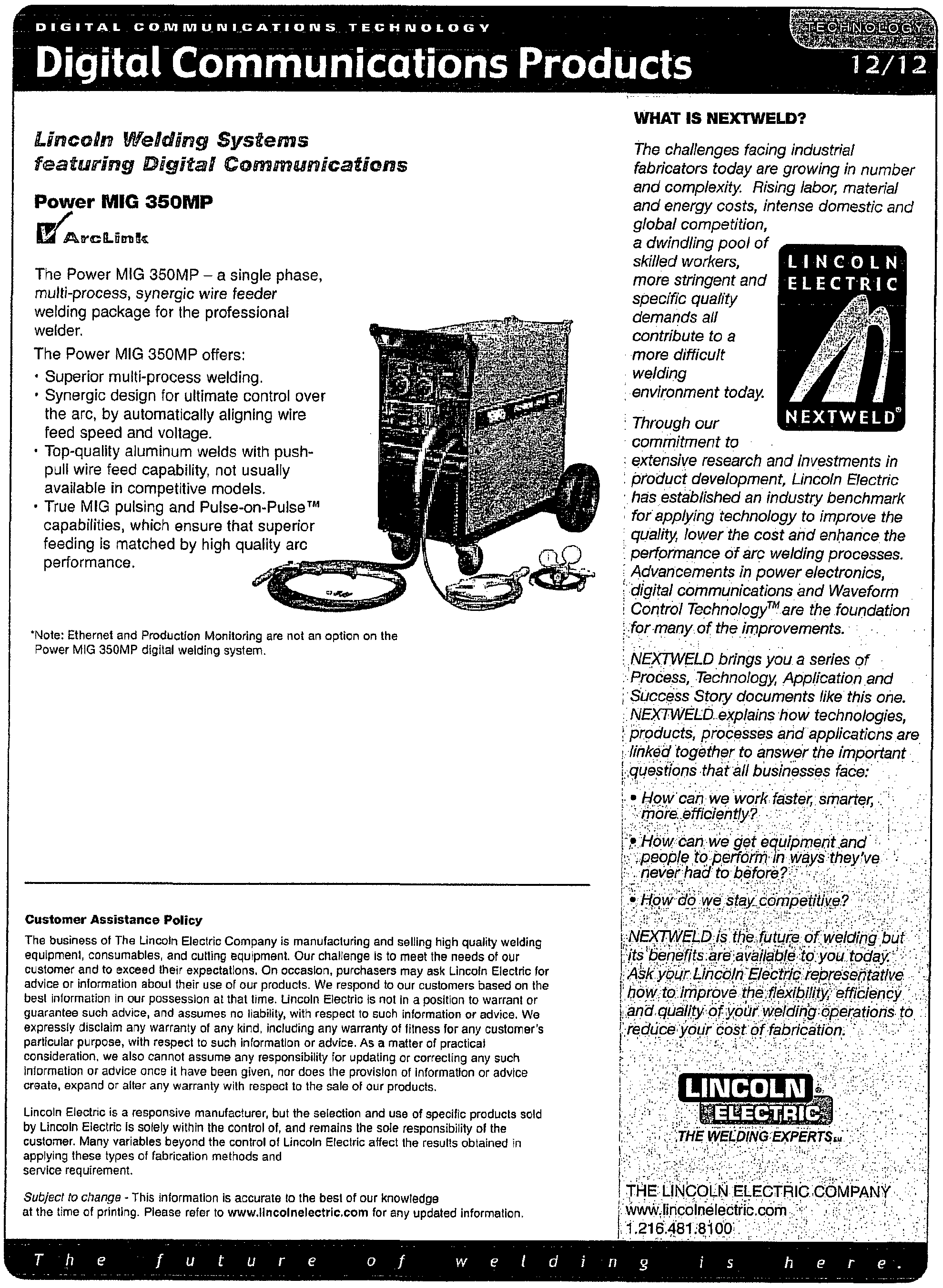
[0003] The following documents may be beneficial to a more thorough understanding and appreciation of the general inventive concepts set forth herein: U.S. Pat. Nos. 5,278,390 to Blankenship; 5,500,512 to Goldblatt; 5,553,810 to Bobeczko; 5,708,253 to Bloch et al.; 5,862,071 to Scholder; 6,536,660 to Blankenship et al.; and 6,858,817 to Blankenship et al.; the article entitled What Every Engineer Should Know about Welding, D. K. Miller (1997) (attached hereto as Appendix 1 ); and the publication entitled Digital Communications Technology (Lincoln Electric 2006) (attached hereto as Appendix 2). Accordingly, each of these documents is hereby incorporated herein by reference in its entirety.
BACKGROUND
[00004] Near field communication, abbreviated NFC, is a form of contactless communication between devices like smartphones or tablets. NFC encompasses a set of standards for such devices, which are often handheld or otherwise mobile, to establish radio communication with each other by touching them together or bringing them into close proximity, usually no more than a few centimeters. NFC peer-to-peer communication is possible provided both devices are powered.
Communication is also possible between an NFC device and an unpowered NFC chip, often called a "passive tag" or simply "tag."
[0005] NFC is a short-range, low-power communications protocol between two devices.
An initiator device uses magnetic induction to create a radio-wave field that a target device can detect and access, allowing small amounts of data to be transferred wirelessly over a relatively short distance (e.g., less than 10 cm). More specifically, by using magnetic induction, the initiator device emits a small electric current, which creates a magnetic field that in turn bridges the physical space between the initiator device and the target device. The field is received by a similar coil in the target device, where it is turned back into electrical impulses to communicate data such as status information or any other information. So-called "passive" NFC tags use the energy from the initiator device to encode their response, while "active" or "peer-to-peer" tags have their own power source and respond to the initiator device using their own electromagnetic fields. Thus, NFC transmissions typically encompass two modes. In a passive communication mode, the initiator device provides a carrier field and the target device answers by modulating the existing field. In this mode, the target device may draw its operating power from the initiator-provided electromagnetic field, thus making the target device a transponder. In an active communication mode, both the initiator device and the target device communicate by alternately generating their own fields. A device deactivates its radio frequency (RF) field while it is waiting for data. In this mode, both devices typically have power supplies.
[0006] NFC devices may be able to receive and transmit data at the same time. Accordingly, the devices can check for potential collisions if the received signal frequency does not match with the transmitted signal's frequency.
[0007] NFC operates within the globally available and unlicensed radio frequency ISM band of 13.56 MHz. Most of the RF energy is concentrated in the allowed ±7 kHz bandwidth range, but the full spectral envelope may be as wide as 1.8 MHz when using ASK modulation. The working distance with compact standard antennas may extend up to 20 cm, but the practical working distance is smaller.
[0008] NFC transmissions are generally secure due to their short range and support for encryption. Applications will often use higher-layer cryptographic protocols (e.g., SSL) to establish a
secure channel. Because loss of an NFC device may present a security issue, such devices are typically protected by additional security, such as an authentication code.
[0009] The NFC standards cover communications protocols and data exchange formats, which offer a secure connection with relatively simple setup, and can be used to bootstrap more capable wireless connections, such as Bluetooth and Wi-Fi connections.
[0010]Application of NFC transmissions and related communications to welding systems and methods are contemplated by the general inventive concepts, as shown and described herein.
BRIEF DESCRIPTION OF THE DRAWINGS
[001 1] The general inventive concepts as well as embodiments and advantages thereof are described below in greater detail, by way of example, with reference to the drawings in which:
[0012] Figure 1 is a schematic drawing of a MIG welding system.
[0013] Figure 2 is an embodiment of a welding system incorporating NFC logic and NFC capable devices.
[0014] Figures 3A and 3B are schematic drawings of passive and active NFC devices or tags, respectively.
[0015] Figure 4 is a schematic drawing of a power source including an NFC tag.
[0016] Figure 5 is a schematic drawing of a gas source including an NFC tag.
[0017] Figure 6 is a schematic drawing of a wire source including an NFC tag.
[0018] Figure 7 is a schematic drawing of a welding torch including an NFC tag.
[0019] Figure 8 is a schematic drawing of a welder including an NFC tag.
[0020] Figure 9 is a schematic drawing of a wire feeder including an NFC tag.
[0021 ] Figure 10 is a schematic drawing of an operator device including active NFC logic.
[0022] Figure 11 is a logic flow chart of a process for limiting access to certain welder functions using NFC logic.
[0023] Figure 12 is a logic flow chart of a process for securing calibration data to welding devices that comprise a welding system.
[0024] Figure 13 is a logic flow chart of a method for setting up and calibrating a welding system using NFC devices.
[0025] Figure 14 is a logic flow chart of a method for configuring a network for a welding system using NFC tags.
BRIEF SUMMARY
[0026] Systems and methods for reading data from and/or writing data to various components of a welding installation are provided. The data is exchanged between devices using near field communication. In one embodiment, the invention provides a welding system, a welder; a wire feeder; a welding torch; a communication means for receiving NFC signals connected to a weld controller of the welder. Further embodiments, features and aspects of the invention are inferable from the ensuing description, drawings and claims.
DETAILED DESCRIPTION
[0027] While the general inventive concepts are susceptible of embodiment in many different forms, there are shown in the drawings and will be described herein in detail specific embodiments thereof with the understanding that the present disclosure is to be considered as merely an exemplification of the principles of the general inventive concepts. Accordingly, the general inventive concepts are not intended to be limited to the specific embodiments illustrated herein.
[0028] The following are definitions of various terms that may be used throughout the disclosure. Both singular and plural forms of all terms fall within each meaning:
[0029] "Logic," synonymous with "circuit" as used herein includes, but is not limited to, hardware, firmware, software and/or combinations of each to perform a function(s) or an action(s). For example, based on a desired application or particular need(s), logic may include a software controlled microprocessor, discreet logic such as an application specific integrated circuit (ASIC), or other programmed logic device. In some instances, logic could also be fully embodied as software.
[0030] "Software" or "computer program" as used herein includes, but is not limited to, one or more computer readable and/or executable instructions that cause a computer or other electronic device to perform functions, initiate actions, and/or behave in a desired manner. The instructions may be embodied in various forms such as routines, algorithms, modules or programs including separate applications or code from dynamically linked libraries. Software may also be implemented
in various forms such as a stand-alone program, a function call, a servlet, an applet, instructions stored in a memory, part of an operating system or other type of executable instructions. It will be appreciated by one of ordinary skill in the art that the form of software is dependent on, for example, the requirements of a particular application, the environment it runs on, and/or the desires of a designer/programmer or the like.
[0031] "Computer" or "processing unit" as used herein includes, but is not limited to, any programmed or programmable electronic device that can store, retrieve, and process data.
[0032] "Operator" as used herein includes, but is not limited to, any individual actually performing a welding operation, as well as any individual supervising or otherwise responsible for a welding operation (whether manual or automatic).
[0033] Electric arc welding is a complicated process wherein numerous interrelated and non-interrelated parameters affect the deposition of molten metal to a weld pool in performing a welding operation. Accordingly, many modern electric arc welders include memory or similar structure for storing information useful for performing or otherwise controlling welding processes. The information can include, for example, information directly related to the welding process, such as parameters for controlling the welder, and/or information indirectly related to the welding process, such as information on an operator performing the welding process or information related to a wire being used in the welding process. Systems and methods for efficiently, reliably, and securely inputting such information are desirable.
[0034] The general inventive concepts contemplate systems and methods which use NFC active and/or passive devices to read, write, and/or store information within a welding system, including amongst various components of the welding system (e.g., a power supply/controller) and operators thereof.
[0035] Metal inert gas (MIG) welding, a subset of gas metal arc welding (GMAW), is one type of electric arc welding. MIG welding is a welding process in which an electric arc forms between a consumable wire electrode and workpiece metals, causing the metals, along with the wire, to melt and join. Along with the wire electrode, a shielding gas is often fed through a welding gun or torch to shield the process from contaminants (e.g., oxygen, nitrogen) in the air. While the various exemplary embodiments set forth herein may be directed to one or more specific types of welding
processes, the general inventive concepts are not intended to be limited to these specific types of welding processes and may find applicability with any suitable welding process.
[0036] A conventional MIG welding system 100 is shown in FIG. 1. In the MIG welding system 100, a welding unit (welder) 102 functions as a power supply and controller for a welding process. The welder 102 includes a memory 104 or similar logic for storing information relating to the welding process. For example, the information could be stored in the memory by an operator 106 manually programming or otherwise interacting with the welder 02.
[0037] The welder 102 is connected to a power source 110 that supplies the necessary input power 112 to operate the welder 102. The welder 102 may condition the input power 112 to produce a consistent or otherwise controlled output power 114 suitable for the welding process.
[0038] The welder 102 is also connected to a gas source 120 that supplies a shielding gas
122 for the welding process. A gas regulator may be used to regulate a pressure of the shielding gas 122 for controlled delivery to the welder 102.
[0039] The welder 102 is also connected to a wire feeder 130. The wire feeder 130 receives a welding wire 32 from a wire source 134, such as a spool or barrel of wire. The wire feeder 130 includes a motor or the like for paying out the welding wire 132 to a welding torch 140, gun, or the like. The wire feeder 130 may advance the welding wire 132 in response to action by the operator 106, such as the operator 106 pressing a switch on the torch 140.
[0040] In the illustrated embodiment, the output power 114 and/or the shielding gas 122 are also fed (e.g., using cables) through the wire feeder 130 to the welding torch 140. In another embodiment, the output power 114 and/or the shielding gas 122 can be fed directly from the welder 102 to the welding torch 140.
[0041] At least one workpiece 150 to be welded is also provided. The workpiece 150 is connected to the welder 102 by a ground cable 152 or the like.
[0042] A MIG welding system 200, according to one exemplary embodiment of the general inventive concepts, is shown in FIG. 2. As described herein, one or more components of the MIG welding system 200 are NFC-capable components. Accordingly, data can be read from and/or written to these components resulting in a more dynamic welding system.
■r -
[0043] In the MIG welding system 200, a welding unit (welder) 202 functions as a power supply and controller for a welding process. The power supply and the controller for the welding process could also be discrete units. The welder 202 can include a processing unit (not shown) for implementing and/or assisting with these (and other) functions. The processing unit can be an internal component of the welder 202, or an external component which the welder 202 accesses (e.g., over a network).
[0044] The welder 202 also includes a memory 204 or similar logic for storing information relating to the welding process. The information can be stored in the memory at any time. For example, the information could be stored in the memory 204 when the welder 202 is manufactured. As another example, the information could be stored in the memory 204 or otherwise updated after installation of the welder 202, such as by the operator 106.
[0045] The welder 202 can include NFC logic 206 including any related logic, software, structure, and the like, such as a power supply. The NFC logic 206 renders the welder 202 capable of sending and/or receiving NFC transmissions.
[0046] The welder 202 is connected to a power source 210 that supplies the necessary input power 112 to operate the welder 202. The welder 202 may condition or otherwise alter the input power 112 to produce a consistent or otherwise controlled output power 114 suitable for the welding process.
[0047] The power source 210 can include NFC logic 216 including any related logic, software, structure, and the like, such as a power supply. The NFC logic 216 renders the power source 210 capable of sending and/or receiving NFC transmissions.
[0048] The welder 202 is also connected to a gas source 220 that supplies a shielding gas
122 for the welding process. A gas regulator (not shown) may be used to regulate a pressure of the shielding gas 22 for controlled delivery to the welder 202.
[0049] The gas source 220 can include NFC logic 226 including any related logic, software, structure, and the like, such as a power supply. The NFC logic 226 renders the gas source 220 capable of sending and/or receiving NFC transmissions.
[0050] The welder 202 is also connected to a wire feeder 230. The wire feeder 230 receives a welding wire 132 from a wire source 234, such as a spool or barrel of wire. The wire feeder
230 includes a motor or the like for paying out the welding wire 132 to a welding torch 240, gun, or the like. The wire feeder 230 may advance the welding wire 132 in response to action by the operator 106, such as the operator 106 pressing a switch on the welding torch 240. In an automated (e.g., robotic) installation, the wire feeder 230 can automatically advance the welding wire 132 in accordance with a computer program or the like associated with the welding process.
[0051] The wire feeder 230 can include NFC logic 236 including any related logic, software, structure, and the like, such as a power supply. The NFC logic 236 renders the wire feeder 230 capable of sending and/or receiving NFC transmissions.
[0052] The wire source 234 can include NFC logic 238 including any related logic, software, structure, and the like, such as a power supply. The NFC logic 238 renders the wire source 234 capable of sending and/or receiving NFC transmissions.
[0053] The torch 240 can include NFC logic 248 including any related logic, software, structure, and the like, such as a power supply. The NFC logic 248 renders the torch 240 capable of sending and/or receiving NFC transmissions.
[0054] In one exemplary embodiment, the output power 14 and/or the shielding gas 122 are also fed (e.g., using cables) through the wire feeder 230 to the welding torch 240. In one exemplary embodiment, the output power 114 and/or the shielding gas 122 are fed directly from the welder 202 to the welding torch 240.
[0055] At least one workpiece 150 to be welded is also provided. The workpiece 150 is connected to the welder 202 by a ground cable 152 or the like.
[0056] Other components of or related to the MIG welding system 200 can include NFC logic including any related logic, software, structure, and the like, such as a power supply. For example, a device 250 associated with the operator 106 can include such NFC logic 256. In one exemplary embodiment, the device 250 is portable so that it can be carried around a work site by the operator 106. In one exemplary embodiment, the device 250 includes a processing unit that provides additional functionality, such as the ability to make phone calls, receive e-mails, take pictures, etc. The NFC logic (e.g., the NFC logic 256) renders the component (e.g., the device 250) capable of sending and/or receiving NFC transmissions.
[0057] The general inventive concepts contemplate welding systems, such as the MIG welding system 200, which include at least one NFC-enabled component. In this manner, the welding systems include at least one component for which data can be read from and/or written to, resulting in enhanced, dynamic welding systems.
[0058] The power source 210 (e.g., a 1 10V electrical outlet) can be viewed as a component of the MIG welding system 200 to the extent it represents a power source for providing power (e.g., the input power 112) to the welder 202 so that the welder 202 can in turn generate and control power (e.g., the output power 1 14) for other components of the MIG welding system 200. In one exemplary embodiment, the power source 210 includes passive NFC logic 402 (see FIG. 4). The NFC logic 402 can take any suitable form. In one exemplary embodiment, the NFC logic 402 is a tag, sticker, or the like. In one exemplary embodiment, the tag is affixed to an outer surface of the power source 210. The tag is readily visible to and accessibly by a user (e.g., the operator 106).
[0059] As a passive device, the tag has no dedicated power supply. Instead, the tag functions as a target device 302 which includes NFC logic 304 and is powered by an electromagnetic field 306 generated by NFC logic 308 of an initiator device 310 (see FIG. 3A). The initiator device 310, as an active device, includes a dedicated power supply 312 (e.g., one or more batteries). In one exemplary embodiment, the initiator device 310 uses read instructions 314 communicated by the field 306 to read information stored on or otherwise associated with the target device 302. The read instructions 314 may be implemented by an NFC application (not shown) running on the initiator device 310. In one exemplary embodiment, the initiator device 310 uses write instructions 318 communicated by the field 306 to write information to the target device 302. The write instructions 318 can also be implemented or otherwise managed by the NFC application running on the initiator device 310.
[0060] The passive NFC logic 402 allows power source information 404 to be stored at or otherwise associated with the power source 210. The power source information 404 can include any information on the power source 210, such as its output power capabilities. The power source information 404 can be accessed by the initiator device 310 and used, for example, to verify that the power source 210 is capable of safely (i.e., rated for) providing sufficient output power for the weld-
ing process. If some deficiency or other issue is identified with the power source 210, the welding process can be prevented or otherwise delayed until said deficiency is remedied.
[0061] In one exemplary embodiment, the gas source 220 includes passive NFC logic 502
(see FIG. 5). The NFC logic 502 can take any suitable form. In one exemplary embodiment, the NFC logic 502 is a tag, sticker, or the like. In one exemplary embodiment, the tag is affixed to an outer surface of the gas source 220 (e.g., one or more tanks containing the shielding gas 122). The tag is readily visible to and accessibly by a user (e.g., the operator 106).
[0062] As a passive device, the tag has no dedicated power supply. Instead, the tag functions as a target device 302 which includes NFC logic 304 and is powered by an electromagnetic field 306 generated by NFC logic 308 of an initiator device 310 (see FIG. 3A). The initiator device 310, as an active device, includes a dedicated power supply 312 (e.g., one or more batteries). In one exemplary embodiment, the initiator device 310 uses read instructions 314 communicated by the field 306 to read information stored on or otherwise associated with the target device 302. The read instructions 314 may be implemented by an NFC application (not shown) running on the initiator device 310. In one exemplary embodiment, the initiator device 310 uses write instructions 318 communicated by the field 306 to write information to the target device 302. The write instructions 318 can also be implemented or otherwise managed by the NFC application running on the initiator device 310.
[0063] The passive NFC logic 502 allows gas source information 504 to be associated with the gas source 220. The gas source information 504 can include any information on the gas source 220, such as a composition of the shielding gas 122 provided thereby. The gas source information 504 can be accessed by the initiator device 310 and used, for example, to determine whether the shielding gas 122 provided by the gas source 220 is proper for the particular welding process. If some deficiency or other issue is identified with the shielding gas 122, the welding process can be prevented or otherwise delayed until said deficiency is remedied.
[0064] In one exemplary embodiment, the wire source 234 includes passive NFC logic 602
(see FIG. 6). The NFC logic 602 can take any suitable form. In one exemplary embodiment, the NFC logic 602 is a tag, sticker, or the like. In one exemplary embodiment, the tag is affixed to an
outer surface of the wire source 234 (e.g., a spool containing the welding wire 132). The tag is readily visible to and accessible by a user (e.g., the operator 106).
[0065] As a passive device, the tag has no dedicated power supply. Instead, the tag functions as a target device 302 which includes NFC logic 304 and is powered by an electromagnetic field 306 generated by NFC logic 308 of an initiator device 310 (see FIG. 3A). The initiator device 310, as an active device, includes a dedicated power supply 312 (e.g., one or more batteries). In one exemplary embodiment, the initiator device 310 uses read instructions 314 communicated by the field 306 to read information stored on or otherwise associated with the target device 302. The read instructions 314 may be implemented by an NFC application (not shown) running on the initiator device 310. In one exemplary embodiment, the initiator device 310 uses write instructions 318 communicated by the field 306 to write information to the target device 302. The write instructions 318 can also be implemented or otherwise managed by the NFC application running on the initiator device 310.
[0066] The passive NFC logic 602 allows welding wire information 604 to be associated with the wire source 234. The welding wire information 604 can include any information on the wire source 234, such as a composition and/or size (e.g., diameter) of the welding wire 132 provided thereby. The welding wire information 604 can be accessed by the initiator device 310 and used, for example, to determine whether the welding wire 132 provided by the wire source 234 is suitable for the particular welding process. If some deficiency or other issue is identified with the welding wire 132, the welding process can be prevented or otherwise delayed until said deficiency is remedied.
[0067] In one exemplary embodiment, the welding torch 240 includes passive NFC logic
702 (see FIG. 7). The NFC logic 702 can take any suitable form. In one exemplary embodiment, the NFC logic 702 is a tag, sticker, or the like. In one exemplary embodiment, the tag is affixed to an outer surface of the welding torch 240 (e.g., on in proximity to a handle 246 of the welding torch 240). The tag may be protected from the harsh welding conditions encountered near the welding torch 240 in any suitable manner. For example, the tag can be made from or otherwise surrounded by a heat resistant material to compensate for the harsh welding conditions. As another example, the tag can be disposed behind a removable panel or the like of the welding torch 240 in order to
shield the tag from the harsh welding conditions. The tag is readily visible to and accessibly by a user (e.g., the operator 106).
[0068] As a passive device, the tag has no dedicated power supply. Instead, the tag functions as a target device 302 which includes NFC logic 304 and is powered by an electromagnetic field 306 generated by NFC logic 308 of an initiator device 310 (see FIG. 3A). The initiator device 310, as an active device, includes a dedicated power supply 312 (e.g., one or more batteries). In one exemplary embodiment, the initiator device 310 uses read instructions 314 communicated by the field 306 to read information stored on or otherwise associated with the target device 302. The read instructions 314 may be implemented by an NFC application (not shown) running on the initiator device 310. In one exemplary embodiment, the initiator device 310 uses write instructions 318 communicated by the field 306 to write information to the target device 302. The write instructions 318 can also be implemented or otherwise managed by the NFC application running on the initiator device 310.
[0069] The passive NFC logic 702 allows torch information 704 to be associated with the welding torch 240. The torch information 704 can include any information on the welding torch 240, such as a maintenance history of the welding torch 240. The torch information 704 can be accessed by the initiator device 310 and used, for example, to determine whether the welding torch 240 is in a satisfactory condition for performing the particular welding process. If some deficiency or other issue is identified with the welding torch 240, the welding process can be prevented or otherwise delayed until said deficiency is remedied.
[0070] In one exemplary embodiment, the welder 202 includes active NFC logic 802 (see
FIG. 8). The NFC logic 802 can take any suitable form. In one exemplary embodiment, the NFC logic 802 is a tag, sticker, or the like. In one exemplary embodiment, the tag is affixed to an outer surface of the welder 202 (e.g., a frame of the welder 202). The tag is readily visible to and accessible by a user (e.g., the operator 106).
[0071] As an active device, the tag has a dedicated power supply 804 (e.g., one or more batteries) which powers its NFC logic 802. In this manner, the tag can function as both an initiator device, such as the initiator device 310, and an active target device 330 (see FIG. 3B).
[0072] The target device 330 has its own power supply 332. The target device 330 further includes NFC logic 334 which can generate an electromagnetic field 336 similar to the electromagnetic field 306 generated by the initiator device 310. In this manner, the target device 330 and the initiator device 310 can engage in peer-to-peer communications with one another. Otherwise, when the target device 330 acts strictly as a target device, it functions in a manner similar to the target device 302 shown in FIG. 3A.
[0073] Conversely, when the target device 330 acts as an initiator device or a combination initiator-target device, it functions in a manner similar to the initiator device 310 shown in FIG. 3A. For example, the target device 330 uses read instructions 314 communicated by its field 336 to read information stored on or otherwise associated with the other device (e.g., the initiator device 310). The read instructions 314 may be implemented by an NFC application (not shown) running on the target device 330. In one exemplary embodiment, the target device 330 uses write instructions 318 communicated by its field 336 to write information to the other device. The write instructions 318 can also be implemented or otherwise managed by the NFC application running on the target device 330.
[0074] When the target device 330 acts as the initiator device 310, the welder 202 can use the NFC logic 802 to read data from and/or write data to another component of the MIG welding system 200 (as a target device). When the target device 330 acts as the target device 302, the welder 202 can use the NFC logic 802 to store welder information which can be read and/or written by another component of the MIG welding system 200 (as an initiator device). Accordingly, the welder 202 can participate in peer-to-peer communications with other components of the MIG welding system 200, including any operators (e.g., operator 106) thereof.
[0075] The active NFC logic 802 allows welder information 806 to be associated with the welder 202. The welder information 806 can include the power source information 404, the gas source information 504, the welding wire information 604, the torch information 704, and/or the wire feeder information 906, as well as any other information relating to the welding process, other components of the MIG welding system 200, and/or operators thereof.
[0076] The welder information 806 can be accessed by any initiator device 310 and used, for example, to determine the requirements and/or parameters associated with a particular welding
process. If some deficiency, issue, problem, or the like, is identified from the welder information 806, the welding process can be prevented or otherwise delayed until said deficiency is remedied. In one exemplary embodiment, the deficiency is remedied automatically by the welding component representing the initiator device 310.
[0077] In one exemplary embodiment, other components of the MIG welding system 200, instead of or in addition to the welder 202, can be active devices. For example, the wire feeder 230 includes active NFC logic 902 (see FIG. 9). The NFC logic 902 can take any suitable form. In one exemplary embodiment, the NFC logic 902 is a tag, sticker, or the like. In one exemplary embodiment, the tag is affixed to an outer surface of the wire feeder 230 (e.g., a housing of the wire feeder 230). The tag is readily visible to and accessibly by a user (e.g., the operator 106).
[0078] As an active device, the tag has a dedicated power supply 904 (e.g., one or more batteries) which powers its NFC logic 902. In this manner, the tag can function as both an initiator device, such as the initiator device 310, and an active target device 330 (see FIG. 3B).
[0079] The target device 330 has its own power supply 332. The target device 330 further includes NFC logic 334 which can generate an electromagnetic field 336 similar to the electromagnetic field 306 generated by the initiator device 310. In this manner, the target device 330 and the initiator device 310 can engage in peer-to-peer communications with one another. Otherwise, when the target device 330 acts strictly as a target device, it functions in a manner similar to the target device 302 shown in FIG. 3A.
[0080] Conversely, when the target device 330 acts as an initiator device or a combination initiator-target device, it functions in a manner similar to the initiator device 310 shown in FIG. 3A. For example, the target device 330 uses read instructions 314 communicated by its field 336 to read information stored on or otherwise associated with the other device (e.g., the initiator device 310). The read instructions 314 may be implemented by an NFC application (not shown) running on the target device 330. In one exemplary embodiment, the target device 330 uses write instructions 318 communicated by its field 336 to write information to the other device. The write instructions 318 can also be implemented or otherwise managed by the NFC application running on the target device 330.
[0081] When the target device 330 acts as the initiator device 310, the wire feeder 230 can use the NFC logic 902 to read data from and/or write data to another component of the MIG welding system 200 (as a target device). When the target device 330 acts as the target device 302, the wire feeder 230 can use the NFC logic 902 to store wire feeder information which can be read and/or written by another component of the MIG welding system 200 (as an initiator device). Accordingly, the wire feeder 230 can participate in peer-to-peer communications with other components of the MIG welding system 200, including any operators (e.g., operator 106) thereof.
[0082] The active NFC logic 902 allows wire feeder information 906 to be associated with the wire feeder 230. The wire feeder information 906 can include the power source information 404, the gas source information 504, the welding wire information 604, the torch information 704, and/or the welder information 806, as well as any other information relating to the welding process, other components of the MIG welding system 200, and/or operators thereof.
[0083] The wire feeder information 906 can be accessed by any initiator device 310 and used, for example, to determine the requirements and/or parameters associated with a particular welding process. If some deficiency, issue, problem, or the like, is identified from the wire feeder information 906, the welding process can be prevented or otherwise delayed until said deficiency is remedied. In one exemplary embodiment, the deficiency is remedied automatically by the welding component representing the initiator device 310.
[0084] In one exemplary embodiment, limitations of the wire feeder 230 can be communicated to the welder 202 via the wire feeder information 906, such that only those welding processes for which the wire feeder 230 is suitable would be displayed or otherwise made available to the operator 106.
[0085] In one exemplary embodiment, an operator device 1000 associated with the operator 106 includes active NFC logic 1002 (see FIG. 10). In one exemplary embodiment, the NFC logic 1002 is embedded in or otherwise integrated with the operator device 1000. In one exemplary embodiment, the NFC logic 1002 is implemented as an add-on component to the operator device 1000. For example, the operator device 1000 can be provided with NFC capability by interfacing the NFC logic 1002 with the device, such as by plugging it into a port, expansion slot, or the like of the device.
The general inventive concepts contemplate that other components of a welding system (e.g., the MIG welding system 200) could be retrofit with NFC capability in a similar manner.
[0086] The operator device 1000 also includes an NFC application (not shown), which is software facilitating communications between the operator 106 and the various NFC-enabled components of the MIG welding system 200. For example, the NFC application can provide a user interface, as well as manage the exchange of data between NFC-enabled devices.
[0087] In one exemplary embodiment, the operator device 1000 is a mobile device. In one exemplary embodiment, the operator device 1000 is a smartphone. In one exemplary embodiment, the operator device 1000 is a portable computer. In one exemplary embodiment, the operator device 1000 is a tablet (see FIG. 10).
[0088] In one exemplary embodiment, the operator device 1000 is a relatively fixed computer. In this case, it may be necessary to bring an NFC-enabled component (e.g., a spool of wire including NFC logic) to the operator device 1000 in order for communications between the operator device 1000 and the component to be possible. In this case, the operator device 1000 may be able to share data with other components of the MIG welding system 200 (e.g., the welder 202) by means of a network, such as a wired or wireless Ethernet network.
[0089] One of ordinary skill in the art will appreciate that any number or combination of components in the MIG welding system 200 can be NFC-enabled. Furthermore, each such component can be configured for either passive or active NFC. Accordingly, the operator device 1000 can generally be used by the operator 106 to read data from and/or write data to any of the NFC-enabled welding components of the MIG welding system 200, such as the welder 202, the power source 210, the gas source 220, the wire feeder 230, the wire source 234, and the welding torch 240.
[0090] In one exemplary embodiment, the operator device 1000 can include authentication information which is used to implement or otherwise enforce access control in a welding system (e.g., the MIG welding system 200). For example, NFC tags are placed on one or more components of the welding system. The NFC tags include control information which defines access limits or requirements for the components. When the operator device 1000 is brought into proximity with any of the components, an NFC session is established to determine whether the authentication information on the operator device 1000 satisfies the access limits or requirements set forth in the control infor-
mation of the component. In one exemplary embodiment, the operator 106 initiates the NFC session manually (e.g., by pressing a button, icon, or the like on the operator device 1000).
[0091] If the authentication information on the operator device 1000 satisfies the access limits or requirements set forth in the control information of the component, then the operator 106 possessing the operator device 1000 is granted access to the component. Here, access to the component can mean any level of access, such as only reading data from the component, reading data to and writing data from the component, and/or actual use of the component for its intended purpose. Indeed, the control information for a component of the welding system can set forth different levels of access, with the operator 106 only being able to access the component consistent with a level of access that can be established using the authentication information of the operator device 1000. If the authentication information on the operator device 1000 fails to satisfy the access limits or requirements set forth in the control information of the component, then the operator 106 utilizing the operator device 1000 is denied access to the component or any access to the component by the operator 106 is appropriately limited.
[0092] Furthermore, the use of information on the operator device 1000 can be extended to implement specific access control measures.
[0093] For example, in one exemplary embodiment, the operator device 1000 is uniquely associated with a particular operator (e.g., the operator 106). The operator device 1000 can include operator information relating to the operator 106, such as the operator's qualifications to perform a particular welding process.
[0094] The operator information can be used in any suitable manner within the MIG welding system 200. For example, the operator information can be used by the welder 202 and/or welding torch 240 to determine whether the operator 106 is certified to perform a particular welding process. If it is determined that the operator 106 lacks the requisite certification, the welder 202 and/or welding torch 240 could prevent the operator 106 from performing the welding process, such as by disabling equipment necessary for performing the welding process (e.g., the welder 202 and/or the welding torch 240).
[0095] As another example, in one exemplary embodiment, the operator device 1000 includes license key information. The license key information can, for example, define use permis-
sions for licensed technology implemented in the components of a welding system (e.g., the MIG welding system 200).
[0096] Additionally, NFC tags are placed on one or more components of the welding system. The NFC tags include license information which defines access limits or requirements for the components in accordance with one or more licenses relating to the components. When the operator device 1000 is brought into proximity with any of the components, an NFC session is established to determine whether the license key information on the operator device 1000 satisfies the license requirements set forth in the license information of the component. In one exemplary embodiment, the operator 106 initiates the NFC session manually (e.g., by pressing a button, icon, or the like on the operator device 1000).
[0097] If the license key information on the operator device 1000 satisfies the license requirements set forth in the license information of the component, then the operator 106 possessing the operator device 1000 is granted access to the licensed component and/or additional licensed functionality of the component is made available to the operator 106. If the license key information on the operator device 000 fails to satisfy the license requirements set forth in the license information of the component, then the operator 106 utilizing the operator device 1000 is denied access to the licensed component and/or any additional licensed functionality of the component.
[0098] v A method 1100 of enforcing a license in a welding system (e.g., the MIG welding system 200) is shown in FIG. 11.
[0099] According to the method 1 100, an NFC device (e.g., the operator device 1000) or other NFC tag is brought in close proximity to welding equipment (e.g., the welder 202) by a user (e.g., the operator 106) at 1102. In one exemplary embodiment, close proximity means within 10 cm.
[00100] The welding equipment uses NFC to obtain data from the NFC device which is then processed at 1104. In particular, the data is evaluated to determine whether the NFC device constitutes a license at 1106. If it is determined that the NFC device does not constitute a valid license directed to licensed technology of the welding equipment, further processing halts (i.e., the method 1100 resets) and the user is denied access to the welding equipment and/or additional functionality covered by the license. Conversely, if it is determined that the NFC device does constitute a valid
license directed to licensed technology associated with the welding equipment, processing continues to 1108. In 1108, access to the welding equipment and/or additional functionality, as the licensed technology, is made available to the user.
[00101] Thereafter, the method 1100 evaluates whether the NFC device remains in close proximity to the welding equipment at 1110. If it becomes the case that the NFC device is no longer in close proximity to the welding equipment, then the user is denied further access to the welding equipment and/or additional functionality at 1112 and further processing halts (i.e., the method 1100 resets).
[00102] On the other hand, as long as the NFC device remains in close proximity to the welding equipment, the user can continue to use the licensed welding equipment and/or additional functionality. In particular, steps 1110 and 1114 form a loop which is constantly or periodically checked to confirm that access to the welding machine or additional functionality, as the licensed technology, should remain available to the user.
[00103] In a welding system including NFC-enabled components, such as the MIG welding system 200, the capabilities of the welding system and underlying components can be extended to provide an enhanced welding system. For example, using NFC, the components of the welding system can store or otherwise be associated with information, and that information can readily be accessed and used by other components of the welding system. NFC tags present a low-cost solution to adding information to "dumb" devices (i.e., those lacking a dedicated processing unit), such as a spool of wire. For passive NFC tags, no dedicated power source is needed and the tags can have a relatively small footprint. Furthermore, operators of the welding system can readily configure and exchange data with the NFC-enabled components, as well as implement various access control mechanisms. Further still, the NFC transmissions between components and/or operators of the welding system are relatively secure owing to their requirement of close proximity and use of encryption and/or other protection mechanisms. Thus, the general inventive concepts extend to any number of (such as automated, manual, hard automated or semi-automated systems) and all welding processes, including, without limitation, MIG, TIG, GMAW, gas brazing, submerged ARC welding, flux-cored welding, and any other welding processes and methods (a non-exhaustive list of welding processes for which this invention could be used is provided in the attached Appendix 3, which is
incorporated herein in its entirety). NFC can be used to enhance the overall capabilities of any of these welding systems and methods.
[00104] The general inventive concepts extend, for example, to systems and methods for enabling arc welders. By way of overview, in electric arc welding, specific applications often involve a welding procedure specification (WPS) that must be followed for acceptance of the weld. In practice, the WPS for a specific application provides the necessary information to set the electric arc welder and load the electric arc welder with external constituents for the purposes of performing the specified welding process.
[00105] In accordance with one exemplary embodiment, the WPS for a given welding operation is converted to digital data and stored in a memory of a portable, local device (e.g., a smart- phone or tablet, such as the operator device 1000). In one exemplary embodiment, the WPS could be stored in a remote location such as a computer connected to the welder by a network, such as an Ethernet network. Any suitable network would suffice, from a local area network to the Internet. The computer and/or welder could employ a wireless connection to the network.
[00106] In one exemplary embodiment, the digital data comprising the WPS of a specific welding operation is loaded into a memory of a portable device. In various exemplary embodiments, the portable device is instead loaded with a code (e.g., a URL or other network address) which allows the digital data defining the WPS to be directed to the digital process controller of the welder (e.g., over a network). The portable device uses NFC to transmit or otherwise direct the WPS or code to the controller of the electric arc welder.
[00107] Thus, the general inventive concepts encompass the use of NFC for communicating a specific digital data defining WPS or a code identifying a specific WPS to a component of a welding system (e.g., a controller of a welder). In the latter case, the digital data defining the WPS is loaded directly into the controller of the welder from an external source, such as an Ethernet network, accessed using the code.
[00108] As shown in FIG. 2, a welding system 1200, according to one exemplary embodiment, includes a system 1210 that is used to provide control data by line 1212 to determine the operation of welder A by controller 1220. The controller is a standard digital processing device for outputting command signals on line 1222 to govern the operation of power supply 1230, shown as
having positive terminal 1232 and negative terminal 1234. Of course, these terminals can be from a switching network with alternate polarity or can be from a rectifier to give specific polarity for AC, DC positive, or DC negative welding. The power supply 1230 can be, for example, an inverter, down chopper, or other power source architecture. Welder A performs a welding operation at a station schematically illustrated as contact sleeve 1240 for directing current to welding wire or electrode E from supply spool 1250 toward workpiece W. In some instances, a stick electrode may be used. Controller 1220 causes welder A to perform any of a variety of welding processes involving weld parameters (e.g., la, Va, WFS), electrical characteristics (e.g., AC, DC+, DC-), and other definitions of the welding mode (e.g., pulse, spray, globular, short circuit, STT).
[00109] System 1210 includes a disabling circuit 1270 which will not allow controller 1220 to operate unless an enable output is received from the disabling circuit.
[00110] System 1210 also includes a communications means 1280 that includes NFC logic
1282 and a memory 1284 or other storage means. The NFC logic 1282 can be active or passive. The communications means 1280 can also include a processing unit. The communications means 1280 provides NFC functionality to the system 1210. The NFC logic 1282 is operable to communicate (i.e., exchange digital data) with NFC logic 1292 of a portable device 1290, as described herein, to receive digital data therefrom (see FIGS. 3A-3B). The NFC logic 1292 can be active or passive. The digital data transmitted from the portable device 1290 to the system 1210 (via communications means 1280) is indicative of a particular welding procedure specification (WPS). The WPS dictates the parameters of welder A, as well as controls disabling circuit 1270.
[00111] The portable device 1290 can include a memory 1294 or other storage means, in addition to the NFC logic 1292. Prior to its transmission to the system 1210, the digital data can be stored in the memory 1294 of the portable device 1290. The portable device 1290 can also include a processing unit. In one exemplary embodiment, an interface of the portable device 1290 allows a user (e.g., the operator 106) to navigate amongst a plurality of welding procedure specifications in order to specify which WPS is to be sent. In one exemplary embodiment, the portable device 1290 is the operator device 1000 (see FIG. 10).
[00112] In one exemplary embodiment, the disabling circuit 1270 is implemented or otherwise controlled by an internal processing unit. In one exemplary embodiment, the disabling circuit
1270 is implemented or otherwise controlled by an external processing unit, such as a processing unit in the communications means 1280. The disabling circuit 1270 can receive information, such as the digital data, from the communications means 1280 over line 1214.
[00113] Information on one or more external items is also provided to the system 1210. For example, this information could be sent to the system 1210 via an NFC transmission (e.g., from a welding component) which is received by the communications means 1280. As another example, this information could be sent to the system 1210 over a network, such as an Ethernet network connecting various welding components.
[001 14] The information can relate to any one or more actual external items pertinent to a welding process to be performed by the welder A. For example, the information could be indicative of the wire E on spool 1250. As another example, the information could be indicative of the gas used for shielding the welding process. As yet another example, the information could be indicative of a qualification of the person operating welder A (e.g., the operator 106).
[00115] Once the WPS data and information on any external items has been provided, the system 2 0 can proceed with its analysis. In particular, the welding procedure specification from the digital data is input to the controller 1220 and the individual aspects of the WPS (corresponding to the input external items) are compared against the WPS by the disabling circuit 1270. If there is coincidence of data between the desired operation of the welding procedure specification and the external items, an enable signal is directed to the controller 1220 through line 1212. This line also inputs other information relating to the WPS to be performed by welder A. This data bypasses the disable circuit 1270. Welder A is controlled by parameters from the WPS. If welder A is not capable of performing the desired parameters, controller 1220 does not initiate welding.
[001 16] The inclusion of NFC logic in one or more components of the welding system 1200, and the portable device 1290, allows for WPS information to be readily, selectively, and securely delivered to the welder A. Furthermore, use of NFC logic in various welding components can eliminate or reduce the need for a network spanning the components of the welding system 1200. Further still, it is not be necessary to have dedicated power sources at welding components or items in order for the welding components or items to communicate their data (e.g., the information on external items). Furthermore, the disabling circuit 1270 aids in insuring that the controller 1220 only initi-
ates welding when there is coincidence between the desired WPS and the external items related to the welding process to be performed.
[001 17] The general inventive concepts extend, for example, to systems and methods for controlling a welding process or cycle of an arc welder.
[001 18] The systems and methods include digital state tables stored in a memory (e.g., the memory 204) or similar structure of the arc welder (e.g., the welder 202). Each of these state tables includes a plurality of digitally coded welding parameters indicative of a selected function of a specific welding cycle. This information is collectively referred to as weld cycle information herein. One state is performed and completed before the next state is processed. This continues until a total cycle is performed. A weld controller includes means for converting the selected function of a specific digital state in the state table into welding parameters at the output of the arc welder operated by the weld controller.
[001 19] As described herein, the systems and methods can employ a large number of the digital state tables and/or other digital programs which are input or otherwise provided by near field communications (NFC) to the arc welder and/or any related structure (e.g., the weld controller for operating the arc welder). In this manner, the library of weld cycle information available to a welding operator (e.g., the operator 106) is dynamic and can be readily changed. For example, customized and/or new weld cycle information can be created or otherwise obtained outside the welder and then readily loaded therein using NFC.
[00120] As shown in FIG. 13, a welding system 1300, according to one exemplary embodiment, includes communications means 1310 that includes NFC logic 1312. The NFC logic 1312 can be active or passive. The communications means 1310 can also include a memory 1314 or other storage means. The communications means 1310 can also include a processing unit. The communications means 1310 provides NFC functionality to the system 1300.
[00121] The NFC logic 1312 is operable to communicate (i.e., exchange digital data) with
NFC logic 1382 of a portable device 1380, as described herein, to receive digital data therefrom (see FIGS. 3A-3B). The NFC logic 1382 can be active or passive. The digital data transmitted from the portable device 1380 to the communications means 1310 is directed to weld cycle information. The weld cycle information and/or associated data contains all of the parameters for performing a given
generic welding process, such as tungsten inert gas (TIG), MIG, synergetic MIG/MAG pulse welding, etc. Each of the state tables included in the weld cycle information relates to a finite welding cycle which is to be performed in a series of individual steps or states by the welding equipment of the welding system 1300. The steps or successive states are defined by specific parameters.
[00122] The communications means 1310 is connected to or otherwise interfaces with a weld controller 1340 via an interconnect line 1342. The weld controller 1340 includes inputs 1344, 1346 and 1348 so that the actual welding current lw, the arc voltage Va and the wire feed speed FS can be sensed and input into the controller 1340, on lines 1344, 1346, 1348, respectively, for the purpose of adaptively implementing the state table loaded from the communications means 1310 into the controller 1340 for performing any given welding process, pulse profile, or cycle.
[00123] In one exemplary embodiment, a digitally loaded program from communications means 1310 is loaded into controller 1340. The controller 1340 inputs information from the welding operation through lines 1344, 1346 and 1348 for performing the particular welding cycle with the architecture constraints of the cycle dictated by the state table or look up table loaded into the controller. A wire feeder 1350 is controlled by the weld controller 1340 through a control line 352 for driving motor 1350a in accordance with the desired feed speed FS of the particular welding cycle of the state table loaded into the weld controller.
[00124] Referring now more particularly to weld controller 1340, this controller has a standard read out meter 1360 and a manual control 1362 for controlling wire speed or any other desired manual manipulation to be performed by the welding operator during the weld cycle. In many instances, there is no manual manipulation of any welding parameter during the processing of a customized welding cycle by the controller 1340. The illustration of a manual control 1362 in the form of a knob is illustrative in nature and shows the versatility of the welding system 1300.
[00125] The welding system 1300 allows additional operations to be employed by merely loading additional generic or semi-generic state tables into the welding equipment of the welding system 1300. The welding equipment (e.g., the NFC-enabled components) of the welding system 1300 can be provided with dedicated or shared memory areas for storing the weld cycle information and/or any other related information. For example, prior to its transmission from the portable device 1380, the weld cycle information can be stored in the memory 1384 of the portable device 1380.
Upon receipt of the weld cycle information by the communications means 1310, the weld cycle information can be stored in the memory 1314 of the communications means 1310. Thus, any number of customized state tables could be added to the welding system 1300, provided sufficient memory or other storage exists. Accordingly, the welding system 1300 is also readily scalable.
[00126] A method 1400 of communicating weld cycle information, such as customized weld cycle information, to a welding system (e.g., the MIG welding system 200), according to one exemplary embodiment, is shown in FIG. 14.
[00127] According to the method 1400, an NFC device (e.g., the operator device 1000) or other NFC tag is brought in close proximity to welding equipment (e.g., the welder 202) by a user (e.g., the operator 106) at 1402. In one exemplary embodiment, close proximity means within 10 cm.
[00128] The welding equipment uses NFC to obtain data (e.g., the weld cycle information) from the NFC device which is then processed at 1404. The data is stored in a memory of the welding equipment at 1406. In one exemplary embodiment, the data is stored in an external storage device accessible by the welding equipment.
[00129] The welding equipment retrieves the data (e.g., from the memory) and uses it to carry out a welding operation at 1408.
[00130] Because the systems and methods can readily import additional weld cycle information, the systems and methods can be efficiently and securely updated, improved, and changed, without changing any structure, except the software which defines the state tables for the various types of weld cycles. As a result of this enhanced adaptability, the systems and methods should have extended applicability.
[00131] The above description of specific embodiments has been given by way of example.
From the disclosure given, those skilled in the art will not only understand the general inventive concepts and attendant advantages, but will also find apparent various changes and modifications to the structures and methods disclosed. For example, the general inventive concepts are equally applicable to both manual welding systems and processes and automated welding systems and processes.
[00132] Furthermore, notwithstanding any exemplary methods disclosed herein, more or fewer steps may be present in other methods encompassed by the general inventive concepts. Likewise, the order in which the steps are performed can change in different embodiments. It is sought, therefore, to cover all such changes and modifications as fall within the spirit and scope of the general inventive concepts, as described and illustrated herein, and any and all equivalents thereof.
Reference numbers:
100 welding system 318 instructions
102 welder 330 target device
106 operator 332 power supply
110 power source 334 logic
112 input power 336 electromagnetic field
114 output power 402 logic
120 gas source 404 power source information 22 shielding gas 502 logic
130 wire feeder 504 gas source information
132 welding wire 602 logic
134 wire source 604 welding wire information
140 welding torch 702 logic
150 workpiece 704 torch information
152 ground cable 802 logic
200 welding system 804 power supply
202 welder 806 welder information
204 memory 902 logic
206 logic 904 power supply
210 power source 906 wire feeder information
216 logic 1000 operator device
220 gas source 1002 logic
226 logic 1100 method
230 wire feeder 1102 step
234 wire source 1104 step
236 logic 1106 step
238 logic 1108 step
240 welding torch 1110 step
246 handle 1112 step
248 logic 1114 step
250 device 1200 welding system
256 logic 1210 system
302 target device 1212 line
304 logic 1220 controller
306 electromagnetic field 1222 line
308 logic 1230 power supply
310 initiator device 1232 positive terminal
312 power supply 1234 negative terminal
314 instructions 1240 contact sleeve
1250 supply spool 1350a motor
1270 disabling circuit 1352 control line
280 communications means 1360 read out meter
1282 logic 1362 manual control
1284 memory 1380 portable device
1290 portable device 1382 logic
1292 logic 1384 memory
1294 memory 1400 method
1300 welding system 1402 step
1310 communications means 1404 step
1312 logic 1406 step
1314 memory 1408 step
1340 weld controller
1342 interconnect line A welder
1344 input E welding wire/electrode
1346 input lw welding current
1348 input Va arc voltage
1350 wire feeder W workpiece
Appendix 1
From amperage ITHIN THE WELDING INDUSprimary variable in determining
TRY , TH E TERM "WELDING heat input. Generally, an increase in to preheat, PROCEDURE SPECIFICATION" amperage means higher deposition
(or WPS) is used to signify the comrates, deeper penetration, and more there's more to bination of variables used to make a admixture. The amperage flowing certain weld. At a minimum the through an electrical circuit is the WPS (or "Welding Procedure" or same, regardless of where it is meawelding simply "Procedure") consists of: sured. It may be measured with a process (Shielded Metal Arc Welding tong meter or with the use of an procedures than [SMAW], Flux Cored Arc Welding electrical shunt. The role of amper[FCAW], etc.); electrode specification age is best understood in the context meets the eye (AWS A5.1, A5.20, etc.); electrode of heat input and current density classification (E7018, E71T-1, etc.); considerations. For CV welding, an
By Duane K. Miller, P.E. electrode diameter; electrical characincrease in wire feed speed will teristics ( (AC, DC+, DC-); base directly increase amperage. For metal specification (A36, A572 Gr. SMAW on CC systems, the machine 50, etc.); minimum preheat and setting determines the basic amperinterpass temperature; welding curage, although changes in the arc rent (amperage)/wire feed speed; arc length (controlled by the welder) will voltage; travel speed; position of further change amperage. Longer welding; post weld heat treatment; arc lengths reduce amperage.
shielding gas type and flow rate; and • Arc voltage is directly related to joint design details. arc length. As the voltage increases,
The welding procedure is somethe arc length increases, as does the what analogous to a cook's recipe: It demand for arc shielding. For CV outlines the steps required to make welding, the voltage is determined a quality weld under specific condiprimarily by the machine setting, so tions. the arc length is relatively fixed in
CV welding. For SMAW on CC sys¬
EFFECTS OF WELDING VARIABLES tems, however, the arc voltage is
The effects of the variables are determined by the arc length, which somewhat dependent on the welding is manipulated by the welder. As arc process being employed, but general lengths are increased with SMAW, trends apply to all the processes. It the arc voltage will increase, and the is important to distinguish the difamperage will decrease. Arc voltage ference between constant current also controls the width of the weld
(CC) and constant voltage (CV) elecbead, with higher voltages generattrical welding systems. Shielded ing wider beads. Arc voltage has a metal arc welding is always done direct effect on the heat input comwith a CC system, while flux cored putation.
welding and gas metal arc welding • The voltage in a welding circuit generally are performed with CV is not constant, but is composed of a systems. Submerged arc may utilize series of voltage drops. Consider the either. following example: assume the
• Amperage is a measure of the power source delivers a total system amount of current flowing through voltage of 40 volts. Between the the electrode and the work. It is a power source and the welding head
Modern Steel Construction / May 1997
or gun, there is a voltage drop of perhaps 3 volts associated with the
input cable resistance. From the
point of attachment of the work head
to the power source work terminal,
there is an additional voltage drop
of, say, 7 volts. Subtracting the 3
volts and the 7 volts from the original 40 leaves 30 volts for the arc.
This example illustrates how important it is to ensure that the voltages
used for monitoring welding procedures properly recognize any losses
in the welding circuit. The most
accurate way to determine arc voltage is to measure the voltage drop
between the contact tip and the
work piece. However, this may not
be practical for semiautomatic welding, so voltage is typically read from
a point on the wire feeder (where the
gun and cable connection is made),
to the workpiece. For SMAW welding, voltage is not usually monitored, since it is constantly changing
and cannot be controlled except by
the welder. Skilled welders hold
short arc lengths to deliver the best
weld quality.
• Travel speed, measured in inches per minute, is the rate at which
the electrode is moved relative to the
joint. All other variables being Wire feed speed is the preferred electrode extension is increased in a equal, travel speed has an inverse method of maintaining welding proconstant voltage system, the electrieffect on the size of the weld beads. cedures for constant voltage wire cal resistance of the electrode As the travel speed increases, the feed processes. The wire feed speed increases, causing the electrode to be weld size will decrease. Extremely can be independently adjusted and heated. This is known as resistance low travel speeds may result in measured directly, regardless of the heating or "I2R heating". As the reduced penetration, as the arc other welding conditions. It is possiamount of heating increases, the arc impinges on a thick layer of molten ble to utilize amperage as an alterenergy required to melt the electrode metal and the weld puddle rolls native to wire feed speed although decreases. Longer electrode extenahead of the arc. Travel speed is a the resultant amperage for a given sions may be employed to gain highkey variable used in computing heat wire feed speed may vary, depending er deposition rates at a given amperinput (reducing travel speed increason polarity, electrode diameter, elecage. When the electrode extension is es heat input). trode type and electrode extension. increased without any change in
• Wire feed speed is a measure of Although equipment has been availwire feed speed, the amperage will the rate at which the electrode is able for two decades that monitor decrease. This results in less penepassed through the welding gun and wire feed speed, many codes such as tration and less admixture. With the delivered to the arc. Typically meaAWS Dl.l continue to acknowledge increase in electrical stickout, it is sured in inches per minute (ipm), amperage as the primary method for common to increase the machine the deposition rates are directly proprocedure documentation. Dl.l does voltage setting to compensate for the portional to wire feed speed and permit the use of wire feed speed greater voltage drop across the elecdirectly related to amperage. When control instead of amperage, providtrode.
all other welding conditions are ing a wire feed speed-amperage relaIn constant voltage systems, it is maintained constant, an increase in tionship chart is available for compossible to simultaneously increase wire feed speed will directly lead to parison. Specification sheets both the ESO and the wire feed an increase in amperage. For slower supplied by the filler metal manufacspeed in a balanced manner so that wire feed speeds, the ratio of wire turer provide data that support the current remains constant. When feed speed to amperage is relatively these relationships. this is done, higher deposition rates constant and linear. For higher wire • Electrode extension, also known are attained. Other welding varifeed speeds, this ratio may increase, as "electrical stickout" or ESO, is the ables, such as voltage and travel resulting in a higher deposition rate distance from the contact tip to the speed, must be adjusted to maintain per amp, but at the expense of peneend of the electrode. It applies only a stable arc and to ensure quality tration. to the wire fed processes. As the welding. The ESO variable should
always be within the range recominput. strength, the required level of penemended by the manufacturer. 0 Current density is determined tration is a function of the joint β Electrode diameter is another by dividing the welding amperage by design in the weld type. All welds critical variable. Larger electrodes the cross sectional area of the elecare required to deliver a certain can carry higher welding currents. trode. For solid electrodes, the curyield and/or tensile strength, For a fixed amperage, however, rent density is therefore proportionalthough the exact level required is smaller electrodes result in higher al to I/d2. For tubular electrodes a function of the connection design. deposition rates. This is because of where current is conducted by the Not all welds are required to deliver the effect on current density dissheath, the current density is relatminimum specified levels of notch cussed below. ed to the area of the metallic cross toughness. Acceptable levels of
• Polarity is a definition of the section. As the current density undercut and porosity are a function direction of current flow. Positive increases, there will be an increase of the type of loading applied to the polarity (reverse) is achieved when in deposition rates, as well as peneweld. Determination of the most the electrode lead is connected to the tration. The latter will increase the efficient means by which these conpositive terminal of the direct curamount of admixture for a given ditions can be met cannot be left to rent (DC) power supply. The work joint. Notice that this may be the welders, but is determined by lead is connected to the negative teraccomplished by either increasing knowledgeable welding technicians minal. Negative polarity (straight) the amperage or decreasing the elecand engineers who create written occurs when the electrode is connecttrode size. Because the electrode welding procedure specifications and ed to the negative terminal and the diameter is a squared function, a communicate those requirements to work lead to the positive terminal. small decrease in diameter may welders by the means of these docuAlternating current (AC) is not a have a significant effect on deposiments. The WPS is the primary tool polarity, but a current type. With tion rates and plate penetration. that is used to communicate to the AC, the electrode is alternately posi• Preheat and interpass temperawelder, supervisor, and the inspector tive and negative. Submerged arc is ture are used to control cracking how a specific weld is to be made. the only process that commonly uses tendencies, typically in the base The suitability of a weld made by a either electrode positive and elecmaterials. Regarding weld metal skilled welder in conformance with trode negative polarity for the same properties, for most carbon-manthe requirements of a WPS can only type of electrode. AC may also be ganese-silicon systems, a moderate be as good as the WPS itself. used. For a fixed wire feed speed, a interpass temperature promotes Procedural variable values must be submerged arc electrode will require good notch toughness. Preheat and properly selected in order to have a more amperage on positive polarity interpass temperatures greater than WPS appropriate for the application. than on negative. For a fixed 550 degrees F may negatively affect The ability of a welder to follow a amperage, it is possible to utilize notch toughness. When the base written WPS is determined by higher wire feed speeds and deposimetal receives little or no preheat, welder qualification tests (D 1.1-96, tion rates with negative polarity the resultant rapid cooling may also paragraph C4.1.2). The welder may than with positive. AC exhibits a lead to a deterioration of notch not know how or why each particumix of both positive and negative toughness. Therefore, careful conlar variable was selected, although polarity characteristics. trol of preheat and interpass temthese values must be used in produc¬
• The magnetic field that surperatures is critical. tion. The inspector is required to rounds any DC conductor can cause ensure that all welding is done in a phenomenon known as arc blow, PURPOSE OF WPSS accordance with the WPS, observing where the arc is physically deflected The particular values for the varithe technique of each welder on a by the field. The strength of the ables discussed above have signifiperiodic basis (D 1.1 -96, paragraph magnetic field is proportional to the cant affect on weld soundness, 6.5.4). Inspectors do not develop square of the current value, so this mechanical properties, and producWPSs, but they must ensure the prois a more significant potential probtivity. It is therefore critical that cedures exist and are followed (Dl.l- lem with higher currents. AC is less those procedural values used in the 96, paragraph 6.3.1).
prone to arc blow, and can someactual fabrication and erection be The Dl.1-96 Structural Welding times be used to overcome this pheappropriate for the specific requireCode - Steel requires written weldnomenon. ments of the applicable code and job ing procedures for all fabrication
• Heat input is proportional to specifications. Welds that will be performed (Dl.1-96, paragraph 5.5). the welding amperage, times the arc architecturally exposed, for example, These WPSs are required to be writvoltage, divided by the travel speed. should be made with procedures ten, regardless of whether they are Higher heat inputs relate to larger that minimize spatter, encourage prequalified or qualified by test. weld cross sectional areas, and largexceptional surface finish, and have Each fabricator or erector is responer heat affected zones, which may limited or no undercut. Welds that sible for the development of WPSs negatively affect mechanical properwill be covered with fireproofmg, in (Dl.1-96, paragraph 4.1.1.1, 4.6). ties in that region. Higher heat contrast, would naturally have less Confusion about this issue apparentinput generally results in slightly restrictive cosmetic requirements. ly still exists since there continue to decreased yield and tensile strength Many issues must be considered be reports of fabrication being perin the weld metal, and generally when selecting welding procedure formed in the absence of written lower notch toughness because of values. While all welds must welding procedure specifications. the interaction of bead size and heat achieve fusion to ensure their One prevalent misconception is that
if the actual parameters under rective measures to be taken may ment that they be written. The use which welding will be performed necessitate weld removal and of prequalified WPSs still requires meet all the conditions for "prequali- replacement, an activity that routhat the welders be appropriately fied" status, written WPSs are not tinely increases the cost of that parqualified. All the workmanship prorequired. This is not true. As has ticular weld tenfold. Avoiding these visions imposed in the fabrication been shown in the cited code refertypes of unnecessary activities by section of the code apply to prequaliences, the requirement is clear. clear communication has obvious fied WPSs. The only code require¬
The WPS is a communication quality and economic ramifications. ment exempted by prequalification tool, and it is the primary means of There are other economic issues is the nondestructive testing and communication to all the parties to be considered as well. In a most mechanical testing required for involved regarding how the welding general way, the cost of welding is qualification testing of welding prois to be performed. It must therefore inversely proportional to the deposicedures.
be readily available to foremen, tion rate. The deposition rate, in A host of restrictions and limitainspectors and the welders. The turn, is directly tied to the wire feed tions imposed on prequalified weldcode is not prescriptive in its speed of the semiautomatic welding ing procedures do not apply to weldrequirements regarding availability processes. If it is acceptable, for ing procedures that are qualified by and distribution of WPSs. Some example, to make a given weld with test. Prequalified welding proceshop fabricators have issued each a wire feed speed of 200 ipm, then a dures must conform with all the prewelder employed in their organizaweld made at 160 ipm (which may qualified requirements in the code. tion with a set of welding procedures meet all the quality requirements) Failure to comply with a single prethat are typically retained in the would cost approximately 25% more qualified condition eliminates the welder's locker or tool box. Others than the weld made at the optimum opportunity for the welding procehave listed WPS parameters on shop procedure. Conformance with WPS dure to be prequalified (Dl.1-96, drawings. Some company bulletin values can help ensure that conparagraph 3.1).
boards have listings of typical WPSs struction is performed at rates that In order for a WPS to be prequaliused in the organization. Regardless are conducive to the required weld fied, the following conditions must of the method used, WPSs must be quality and are economical as well. be met:
available to those authorized to use The code imposes minimum • The welding process must be prethem. requirements for a given project. qualified. Only SMAW, SAW,
It is in the contractor's best interAdditional requirements may be GMAW (except GMAW-s), and est to ensure that efficient communiimposed by contract specifications. FCAW may be prequalified cation is maintained with all parties The same would hold true regarding (Dl.1-96, paragraph 3.2.1). involved. Not only can quality be WPS values. Compliance with the • The base metal filler metal comcompromised when WPSs are not minimum requirements of the code bination must be prequalified. available, but productivity can suffer may not be adequate under all cirPrequalified base metals, filler as well. Regarding quality, the limcumstances. Additional requiremetals, and combinations are its of suitable operation of the parments can be communicated through shown in Dl.1-96, paragraph 3.3, ticular welding process and electrode the WPS. For example, the Dl.1-96 Table 3.1.
for the steel, joint design and posicode permits the use of an E71T-11 • The minimum preheat and inter- tion of welding must be understood. FCAW electrode for multiple pass pass temperatures prescribed in
Dl.1-96, paragraph 3.3, Table Obviously, the particular electrode welding without any restriction on 3.2 must be employed (Dl.1-96, employed must be operated on the plate thickness. The Lincoln paragraph 3.5).
proper polarity, proper shielding Electric product, Innershield • Specific requirements for the vargases must be used, and amperage NR211MP, has a maximum thickious weld types must be mainlevels must be appropriate for the ness restriction imposed by the mantained. Fillet welds must be in diameter of electrode, and for the ufacturer of ½". This additional accordance with Dl.1-96, parathickness of material on which weldrequirement can be incorporated graph 3.9, plug and slot welds in ing is performed. Other issues may into the applicable WPS. Other recaccordance with Dl.1-96, paranot be as obvious. For example, the ommendations that may be imposed graph 3.10, and groove welds in required preheat for a particular by the steel producer, electrode manaccordance with Dl.1-96, paraapplication is a function of the ufacturer, or others can and should graph 3.11, 3.12, and 3.13 as grade(s) of steel involved, the thickbe documented in the WPS. applicable. For the groove welds, nesses) of material, and the type of whether partial joint penetration electrode employed (whether low PRBQUALIFIED PROCEDURES or complete joint penetration, the hydrogen or non-low hydrogen). All- The AWS Dl.l code provides for required groove preparation of this can be communicated by the use of prequalified WPSs. dimensions are shown in Dl.1-96, means of the written WPS. Prequalified WPSs are those that Figures 3.3 and 3.4.
Lack of conformance with the the AWS Dl Committee has deterEven if prequalified joint details parameters outlined in the WPS mined to have a history of acceptare employed, the welding procedure may result in the deposition of a able performance, and so does not must be qualified by test if other weld that does not meet the quality subject them to the qualification prequalified conditions are not met. requirements imposed by the code or testing imposed on all other welding For example, if a prequalified detail the job specifications. When an procedures. The use of prequalified is used on an unlisted steel, the unacceptable weld is made, the corWPSs does not preclude the requirewelding procedures must be qualified by test.
for the thickness of steel on which the weld is being made is inappropriate. It would not meet the requirements of Dl.1-96, paragraph 5.3.1.2 in the section entitled Fabrication, which requires that the size of electrode and amperage be suitable for the thickness of material being welded. This illustration demonstrates the fact that compliance with all prequalified conditions does not guarantee that the combination of selected variables will always generate an acceptable weld.
Most contractors will determine preliminary values for a prequalified WPS based upon their experience, recommendations from publications such as Lincoln Electric's Procedure Handbook of Arc Welding, industry publications such as the AWS Welding Handbooks, from AWS Welding Procedure Specifications (AWS B2.1), or other sources. It is the responsibility of the contractor to verify the suitability of the suggested parameters prior to the application of the actual procedure on a project, although the verification test need not be subject to the full
range of procedure qualification tests imposed by the code. Typical
Prequalified status requires conIt is the contractor's responsibilitests will be made to determine formance to a variety of procedural ty to ensure that the particular soundness of the weld deposit (e.g., parameters. These are largely conparameters selected within the fusion, tie-in of weld beads, freedom tained in Dl.1-96, Table 3.7, and requirements of the prequalified from slag inclusions, etc.). The plate include maximum electrode diameWPS are suitable for the specific could be nondestructively tested or, ters, maximum welding current, application. An extreme example as is more commonly done, cut, polmaximum root pass thickness, maxiwill serve as an illustration. ished, and etched. The latter operamum fill pass thicknesses, maxiConsider the following example of a tions allow for examination of penemum single-pass fillet weld sizes, hypothetical proposed WPS for tration patterns, bead shapes, and and maximum single pass weld laymaking a ¼" fillet weld on ¼" A36 tie-in. Welds made with prequaliers (Dl.1-96, Table 3.3). In addition steel in the flat position. The weld fied WPSs that meet the physical to all the preceding requirements, type and steel are prequalified. dimensional requirements (fillet welding performed with a prequaliSAW, a prequalified process, is weld size, maximum reinforcement fied WPS must be in conformance selected. The filler metal selected is levels, and surface profile requirewith the other code provisions conF7A2-EM12K, meeting the requirements), and are sound (that is, havtained in the fabrication section of ments of Dl.1-96, Table 3.1. No preing adequate fusion, tie-in and freeAWS Dl.1-96 Structural Welding heat is specified since it would not dom from excessive slag inclusions Code. be required according to Dl.1-96, and porosity) should meet the
The code does not imply that a Table 3.2. The electrode diameter strength and ductility requirements WPS that is prequalified will autoselected is less than the ¼" maximposed by the code for welding promatically achieve the quality condiimum specified in Dl.1-96, Table cedures qualified by test. Weld tions required by the code. The com3.7. The maximum single pass fillet soundness, however, cannot be mentary language for paragraph weld size in the flat position, accordassumed just because the WPS is 3.2.1 states the following: ing to Dl.1-96, Table 3.7, is unlimitprequalified.
"The use of prequalified joints ed, so the ½" fillet size can be preand procedures does not necessarily qualified. The current level selected GUIDELINES guarantee sound welds. Fabrication for making this particular fillet weld When developing prequalified capability is still required, together is 800 amps, less than the 1000 amp WPSs, the starting point is a set of with effective and knowledgeable maximum specified in D l .1-96, welding parameters appropriate for supervision to consistently produce Table 3.7. the general application being considsound welds." (AWS Dl.1-96, paraHowever, the amperage level ered. Parameters for overhead weldgraph C3.2.1) imposed on the electrode diameter ing will naturally vary from those
required for down-hand welding. In the simplest case, the exact conditype of tests required are defined in The thickness of material involved tions that will be encountered in Dl.1-96, Table 4.2 for complete joint will dictate electrode sizes and correproduction will be replicated in the penetration groove welds, Dl.1-96, sponding current levels. The specific procedure qualification test. This Table 4.3 for partial joint penetrafiller metals selected will reflect the would include the welding process, tion groove welds, and Dl .1-96, strength requirements of the connecfiller metal, grade of steel, joint Table 4.4 for fillet welds.
tion. Many other issues must be details, thicknesses of material, preOnce the number of tests has considered. heat values, minimum interpass been determined, the test plate is
Depending on the level of familtemperature level, and the various sectioned and the specimens iarity and comfort the contractor has welding parameters of amperage, machined for testing. The results of with the particular values selected, voltage, and travel speed. The inithe tests are recorded on the PQR. welding a mock-up may be appropritial parameters used to make the According to Dl.1-96, if the test ate. Once the parameters that are procedure qualification test plate results meet all the prescribed desired for use in production are beg for a name to define them, requirements, the testing is successestablished, it is essential to check although there is no standard indusful and welding procedures can be each of the applicable parameters try term. It has been suggested that established based upon the successfor compliance with the Dl.1-96 "TWPS" be used where the T could ful PQR. If the test results are code. alternately stand for temporary, unsuccessful, the PQR cannot be
To assist in this effort, Annex H test, or trial. In any case, it would Used to establish the WPS. If any has been provided in the Dl.1-96 define the parameters to be used for one specimen of those tested fails to code. This contains a check list that making the test plate since the meet the test requirements, two identifies prequalified requirements. validity of the particular parameters retests of that particular type of test If any single parameter deviates cannot be verified until they have may be performed with specimens from these requirements, the consuccessfully passed the required extracted from the same test plate. tractor is left with two options: (1) test. The parameters for the test If both of the supplemental specithe preliminary procedure can be weld are recorded on a Procedure mens meet the requirements, the adjusted to conform with the preQualification Record (PQR). The Dl.1-96 allows the tests to be qualified constraints; or, (2) the actual values used should be recorddeemed successful. If the test plate WPS can be qualified by test. If the ed on this document. The target is over 1½" thick, failure of a specipreliminary procedure is adjusted, it voltage, for example, may be 30 volts men necessitates retesting of all the may be appropriate to reexamine its but, in actual fact, only 29 volts were specimens at the same time from viability by another mock-up. used for making the test plate. The two additional locations in the test
The next step is to document, in 29 volts would be recorded. material (Dl.1-96, paragraph 4.8.5). writing, the prequalified WPS valAfter the test plate has been It is wise to retain the PQRs ues. A sample form is included in welded, it is allowed to cool and the from unsuccessful tests as they may Annex E of the code. The fabricator plate is subjected to the visual and be valuable in the future when may utilize any convenient format nondestructive testing as prescribed another similar welding procedure is (Dl.1-96, paragraph 3.6). Also conby the code. The specific tests contemplated for testing.
tained in Annex E are a series of required are a function of the type of The acceptance criteria for the examples of completed WPSs that weld being made and the particular various tests are prescribed in the may be used as a pattern. welding consumables. The types of code. The reduced section tensile qualification tests are described in tests are required to exceed the min¬
QUALIFYING BY TEST Dl.1-96, paragraph 4.4. imum specified tensile strength of
Conducting qualification tests— In order to be acceptable, the test the steel being joined (Dl.1-96, paraThere are two primary reasons why plates must first pass visual inspecgraph 4.8.3.5). Specific limits on the welding procedures may be qualified tion followed by nondestructive testsize, location, distribution, and type by test. First, it may be a contractuing (NDT) (Dl.1-96, paragraphs of indication on bend specimens is al requirement. Secondly, one or 4.8.1, 4.8.2). At the contractor's prescribed in Dl.1-96, paragraph more of the specific conditions option, either RT or UT can be used 4.8.3.3.
encountered in production may devifor NDT. The mechanical tests Writing WPSs from successful ate from the prequalified requirerequired involve bend tests (for PQRs— When a PQR records the ments. In either case, a test weld soundness), macro etch tests (for successful completion of the required must be made prior to the establishsoundness), and reduced section tentests, welding procedures may be ment of the final WPS. The first sile tests (for strength). For qualifiwritten from that PQR. At a ministep in qualifying a welding procecation of procedures on steels with mum, the values used for the test dure by test is to determine the prosignificantly different mechanical weld will constitute a valid WPS. cedure one wants to qualify. The properties, a longitudinal bend specThe values recorded on the PQR are same sources cited for the prequaliimen is possible (Dl.1-96, paragraph simply transcribed to a separate fied WPS starting points could be 4.8.3.2). All weld metal tensile tests form, now known as a WPS rather used for WPSs qualified by test. are required for unlisted filler metthan a PQR.
These will typically be the parameals. The nature of the bend speciIt is possible to write more than ters used for fabrication of the test mens, whether side, face, or root, is one WPS from a successful PQR. plate, although this is not always a function of the thickness of the Welding procedures that are suffithe case, as will be discussed later. steel involved. The number and ciently similar to those tested can be
a Vis" fillet weld. The specific application conditions, however, will necessitate that a separate WPS be developed for each situation. A sample WPS is included for each situation.
Situation One: The weld to be made is a Vie" fillet weld that connects the shear tab to the column. This weld will be made in the fabrication shop with a column in the horizontal position. The fillet weld is applied to either side of a ½" shear tab. It is welded to a W14x311 column with a flange thickness of 2 > ". The shear tab is made of A36 steel, while the column is of A572 Gr 50.
The welding engineer recognizes that for the grades of steel involved, and for the type of weld specified, a prequalified WPS could be written. The process of choice for this particular shop fabricator is gas shielded flux cored arc welding, a prequalified welding process. From Table 3.1 of the Dl.1-96 code, a list of prequalified filler metals is given. Outershield 70, an E70T-1 electrode is selected because, for semiautomatic welding, it is likely to be the most economical process considering
deposition rate and cleanup time. supported by the same PQR. rather for planning qualification The electrode operates on DC+ Significant deviations from those tests. For example, a test plate conpolarity. From experience, the engineer knows that diameter is conditions, however, require addiducted in the 2G position qualifies
tional qualification testing. Changes the WPS for use in either the 1G or appropriate for the application, and that are significant enough to war2G position. Even though the first specifies that the shielding gas rant additional testing are considanticipated use of the WPS may be should be C02 based upon the elecered essential variables, and these for the 1G position, it may be advistrode manufacturer's recommendaable to qualify in the 2G position so tion and its low cost characteristics. are listed in Dl.1-96, Tables 4.5, 4.6,
and 4.7. For example, consider an that additional usage can be From Table 3.2 of the Dl.1-96 code, the preheat is selected. It is conSMAW welding procedure that is obtained from this test plate.
qualified by test using an E8018-C3 trolled by the thicker steel, that is,
In a similar way, Dl.1-96, Table
7 defines what changes can be the column flange, and required to electrode. From that test, it would 4.
be a minimum of 150 degree F since be possible to write a WPS that utimade in the base metals used in prothe column flange thickness is 2¼". lizes E7018 (since this is a decrease duction vs. qualification testing. An
in electrode strength) but it would alternate steel may be selected for From recommendations supplied by not be permissible to write a WPS the qualification testing simply the electrode manufacturer, the that utilizes E9018-G electrode because it affords additional flexibilwelding engineer selects a welding (because Table 4.5 lists an increase ity for future applications. current of 460 amps, 31 volts, and in filler metal classification strength If WPS qualification is performed specifies that the welding speed as an essential variable). It is on a non-prequalifted joint geometry, should be 15-17 ipm. The final variimportant to carefully review the and acceptable test results are able is determined based upon expeessential variables in order to deterobtained, WPSs may be written from rience. If any doubts still exist, a mine whether a previously conductthat PQR utilizing any of the pre- simple fillet weld test could be made ed test may be used to substantiate qualified joint geometries (Dl.1-96, to verify the travel speed for the the new procedure being contemplatTable 4.5, Item 32). given amperage.
ed. As a quick check, the engineer
Dl.1-96, Table 4.1 defines the EXAMPLES reviews Annex H to ensure that all range of weld types and positions To provide some insight into the the prequalified conditions have qualified by various tests. This thought process that a welding engibeen achieved. Finally, these are table is best used, not as an after- neer may follow to develop a WPS, tabulated on the WPS.
the-fact evaluation of the applicabilitwo examples will be given. In both Situation Two: The second weld ty of the test already conducted, but cases, the weld is the same, namely, to be made is also a Vie" fillet weld,
but in this case, the weld will be ments of this code" (Dl.1-96, paraarc), and flux cored arc WPSs in made in the field. The weld will be graph 6.3.1). The Dl.1-96 code does conjunction with certain related made between the shear tab not require prequalified WPSs to be types of joints have been thordescribed above, and the beam web. submitted to the engineer for oughly tested and have a long In this situation, the beam is a approval. Welding procedures that record of proven satisfactory perW36xl50, specified to be of A36 have been qualified by test are formance." (Dl.1-96, paragraph steel. Under field conditions, the required to be reviewed by the engiC3.2.1).
weld must be made in the vertical neer (Dl.1-96, paragraph 4.1.1). The review required by the position. However, the use of a "prequalified inspector in Dl .1-96, paragraph
The welding engineer again recjoint" does not exempt the engineer 6.3.1 does not specifically require a ognizes that the WPS for this applifrom using engineering judgment in determination regarding the suitcation could be prequalified if all the determining the suitability of appliability of the procedure for the parapplicable conditions are met. Self cation for these joints (Dl.1-96, ticular application, but rather shielded flux cored arc welding is paragraph 3.1). The code is not requires that the procedure conform selected in order to ensure high explicit with respect to engineering to the requirements of the code. As quality welds under windy condiresponsibility for the other aspects previously stated, the engineer is tions. This is a prequalified process. of a prequalified WPS. not exempted from exercising engiIn D 1.1-96, Table 3.1, the engineer The code is clear that the inspecneering judgment when prequalified locates suitable filler metals and tor is required to review all WPSs. joint details are used.
selects Innershield NR232, an E71T- For a prequalified WPS, Annex H, The previously described respon8 self-shielded flux cored electrode "Contents of a Prequalified WPS", is sibility of the inspector to review all which operates on DC negative particularly helpful. This Annex WPSs applies equally to those qualipolarity. Because the welding will provides a list of the various elefied by test. However, Dl .1-96, be made in the vertical position, a ments of a prequalified WPS, and paragraph 4.1.1 additionally 0.068 in. diameter electrode is specihas a reference to the code pararequires the following:
fied. From technical literature supgraph where these restrictions are "Except for prequalified WPSs in plied by Lincoln Electric, a middle- listed. In the reorganized Dl.1-96 conformance with Section 3, a of-the-range procedure suitable for code format, user-friendly tables and WPS for use in production weldvertical position welding is selected. figures summarize many of the preing shall be qualified in conforThe engineer specifies the current to qualified requirements. These mance with Section 4, Part B, and be 250 amps, 19-21 volts, with a include: shall be approved by the engineer."
travel speed of 5.5-6.5 ipm. The con• Table 3.1 - Prequalified Base
trolling variable is the thickness of Metal - Filler Metal Combinations The apparent logic behind the difthe beam web, which is ¾". In this for Matching Strength ferences in approval approaches is situation, Table 3.2 of the Dl.1-96 • Table 3.2 - P r e q u a l i f i e d that while prequalified WPSs are code does not require any minimum Minimum Preheat and Interpass based upon well established, time preheat. Temperatures proven, and documented welding
The two welds to be made are • Table 3.3 - Filler Metal practices (see Dl.1-96, paragraph remarkably similar, and yet the Requirements for Exposed Bare C3.2.1), WPSs that have been qualiWPS values specified are significantApplications of A588 Steel fied by test may utilize new, ly different. In order to ensure that • Table 3.7 - Prequalified WPS unproven and sometimes controverquality welds are delivered at ecoRequirements sial concepts. WPSs that are qualinomical rates, it is imperative that a • Figure 3.3 - P r e q u a l i f i e d fied by test are not automatically knowledgeable individual establish Groove Weld Joint Details subject to the same restrictions that WPS values. These values must be • Figure 3.4 - Prequalified C JP would apply to prequalified WPSs. adhered to during fabrication and Groove Weld Details Even though the required qualificaerection in order to ensure quality In addition to the above tables, tion tests have demonstrated the welds in the final structure. Table 4.5 lists the essential variable adequacy of the particular WPS changes required for WPS requalifi- under test conditions, further scruti¬
REVIEW AND APPROVAL cation. The limitation of variables ny by the engineer is justified to
After a WPS is developed by a prescribed in Table 4.5 also apply to ensure that it is applicable for the fabricator or erector, it is required to prequalified WPSs (Dl.1-96, paraparticular situation that will be be reviewed by the inspector (AWS graph 3.6). Through the use of these encountered in production.
Dl.1-96, paragraph 6.3.1). This tables, the majority of the prequaliTwo examples will be cited to applies whether the WPS has been fied conditions can be easily checked illustrate the philosophical differqualified by test, or whether it is by the inspector as part of the ences a welding engineer may take prequalified. The code requires required review. when evaluating a WPS qualified by WPSs that are qualified by test to be The fundamental premise on test. In Situation One, the contracsubmitted to the engineer for which the suitability of prequalified tor wishes to use a WPS that would approval (Dl.1-96, paragraph 4.1.1). procedures stands is stated in the otherwise be prequalified, except for
Prequalified WPSs are required commentary as follows: one change in the joint detail. Based to be reviewed by the inspector who "Certain shielded metal arc, subupon experience and some informal is required to "make certain that the merged arc, gas metal arc tests, the contractor has determined procedures conform to the require(excluding the short circuiting that a modified groove detail will mode of metal transfer across the reduce the required volume of weld
not preheated prior to fabrication
(although the air temperature inside the shop where the qualification testing is being performed is at 70 degree F). After the first weld pass is applied, the steel temperature rises well above ambient due to the thermal energy added by the welding process. A second weld pass is applied to the first side. Next, the plate is inverted and the root pass made from the opposite side is gouged out. While the interpass temperature is still well above ambient, the second side of the joint is welded. Finally, the plate is flipped one more time, and the first side of the joint is welded out to completion.
The test plate is subject to all of the code-mandated tests, and successfully meets the code requirements. With this information in hand, the contractor submits the procedure to the engineer for approval, claiming that these tests have proven the weldability of the new steel, and that no preheat is required. While it is true that the code-mandated requirements have been fulfilled, the suitability of this welding procedure for actual fabrication has not been established. The relatively small sizes associated with the test plate (1" thick x 14" minimum wide x 30" minimum long, according to Dl.1-96, Figure 4.10) is not sufficient to duplicate the restraint or cooling rates that will be

seen in actual structures. These issues will affect the resultant heat metal without affecting quality. The lem with fusion problems associated affected zone microstructure, hydrojoint detail is similar to a B-U2a-GF, with this technique. A successful gen diffusion rates, and residual except that the root opening and PQR should satisfy the engineer who stress levels - all elements that groove angles deviate from the pre- is required to approve this proceaffect the possibility of weld crackqualified requirements shown in dure. ing. In addition, except for the root Dl.1-96. Specifically, the combinaIn Situation Two, the issue is pass, all of the weld passes had the tion of a ½" root opening with a 45 more complex. A new steel is being benefit of the higher interpass temdegree included angle when applied contemplated for construction, and perature. Furthermore, the root to plate ½" thick provides a near the claim of the steel producer is pass that was made without preheat optimum configuration for this conthat it can be welded with reduced was gouged out when the second tractor's procedures that utilize preheat levels. It cannot be prequal- side was welded. Although no preFCAW-g. Since these dimensional ified because (a) the steel is not heat was applied, the steel was at changes are beyond the limits perprequalified; and, (b) the preheat shop ambient temperature, qualifymitted by the as-detailed tolerances levels are below the prequalified liming a 70 degrees F preheat temperafor the specific joint, they must be its. In order to qualify the procedure ture, not "no preheat" temperature. qualified by test. If there were to be for unlimited thickness qualification, The engineer ought to view the a problem associated with this Dl.1-96, Table 4.2 requires the test second WPS with a greater degree of approach, it would no doubt eviplate be 1 in. or thicker. The conscrutiny than first. It would be readence itself as a fusion-type probtractor qualifies the welding procesonable, for example, to require lem. The required qualification test dure on 1 in. steel, although the weldability tests (such as: G-BOP, as outlined in Table 4.2 require two actual application will utilize 4 in. TEKKEN, or CTS tests) in order to Reduce Section Tension Tests, and thick steel. The actual joint configubetter understand the likely behavfour Side Bend Tests. Both of these ration used for qualification testing ior of this proposed welding procetests, and the Side Bend Test in paris a double V groove butt joint, welddure. Larger scale, restrained mock- ticular, will quickly reveal any probed from two sides. The test plate is
ups would be necessary to evaluate actual restraint and cooling conditions.
When WPSs that have been qualified by test are reviewed, there are three distinct elements of that review: First, the procedure qualification record should be evaluated to ensure that all the required tests have been performed, verifying that the proper thicknesses of material, positions of welding, and number of required tests have all been performed. Secondly, the results of the testing must be examined to be certain that the code requirements have been met. The final aspect of the review is to compare the WPS to the PQR. This will consist of a comparison of the requirements of AWS Dl.1-96, Table 4.5, as it relates to any differences between the PQR and the WPS. Requirements regarding the steels used in testing versus those listed on the WPS are addressed in Dl.1-96, Table 4.7.
The opinions and explanations expressed above are the author's alone and do not necessarily reflect the opinions of the AWS or of the AWS Dl Committee. Official interpretations of the Dl.l code can only be made by the Dl Committee. Dl.1- 96, Annex F, provides information detailing how an official interpretation can be obtained.
This article is based on a paper presented at the 1997 National Stee IConstruction Conference. Duane K. Miller, P.E., is a senior project leader and design consultant at The Lincoln Electric Company's Welding Technology Center.In that capacity, he assists engineers and fabricators in welding design and metallurgical problems.
Appendix 2
The Power Wave 450 was an analog welding system.
New welding features required additional wiring and calibration between the robot and power source. Weld process controls were found on both the welding
teach pendant or hard automation control interface.
SPEED OF PERFORMANCE
Delays are reduced, allowing more data to be transferred in less time.
FLEX!BILITY/SCALABILITY
New features can be added to existing equipment through software upgrades, and new components can easily be added to an existing welding cell.
COST REDUCTION
A single cable between multiple devices is less expensive and more efficient.
S!MPURE© EQUiPMENT MAINTENANCE
Calibration between the power source and robot is not necessary, even after features are added to an existing system.
PROCESS CONTROLS
All weld process controls are accessible from a single user interface control panel.
PRODUCTION MONSTORING
High-speed communications enable the use of software tools to track equipment usage and condition, allow configuration of limits and responses after each weld, and provide storage of thousands of weld summaries.
Integration Possibilities 2/
Seam!ess Integration
Process
FANUC Robot Monitoring
PLC or Hard Automation
OeviceNel Compatible Robot
The ArcLink Protocol
Is ArcLink?
ArcLink is the leading digital
communications protocol for
the arc welding industry. It
integrates all welding
components for seamless,
time-critical data transfer.
The strength of ArcLink lies
in the ability to communicate
with each system component
in a pre-defined welding
language. In addition,
ArcLink is an open
communications protocol,
meaning that Lincoln Electric
publishes how it works and
encourages other companies
to adopt it. . ,
ArcLink brings modularity to
welding systems and provides
a single, intelligent connection
between all modules. An
ArcLink network can be as
simple as a single stick
welder or as complicated as
robotic installations.
ArcLink™ Communications 5/12
Robotic Integration Application
ArcLink greatly improves the integration of the arc welding
process into automated arc welding systems, as the
advanced features of ArcLink provide process changing
(between 8 weld schedules), file transfer, data acquisition,
and component fault history capabilities.
Semiautomatic Application
ArcLink is used in semiautomatic applications as the method
of communication internal to each welding component.
ArcLink provides many of the same benefits to semiautomatic
applications as it does to robotics, such as:
• data monitoring
• access to all weld process controls from a single user
• ability to boom-mount user interfaces Power Wave F355i/FANUC RJ3iB is an example of an ArcLink Specifications ArcLink Robotic Welding System
• 5-conductor SO-type control cable with 5-pin connectors
for all interconnections
• Isolated 40 VDC power supply
• ultiple-sourced transceiver
• Data rate of 125-500 Kbaud
Features
Of ArcLink
File Transfer
• Weld files can be saved, shared, or modified.
Data Acquisition
• Weld data is collected and stored for
Production Monitoring™ purposes.
Advanced Diagnostics
• ArcLink provides the capability to monitor component
failures system wide.
■ Uses one control cable for communications, component ArcLink Robotic systems allow weld mode searches by process power, and electrode voltage sensing connections. and wire type through the robot teach pendant.
• Provides flexibility of physical configuration so that any
component may be connected to any other component in
the system.
Performance
• Provides a repeatable and reliable method of
Of Using ArcLink communication for time-critical welding applications.
Modular System Configuration • Improves welding performance by increasing the
• Allows for creation of custom welding amount of shared information between welding system configurations. system components.
Rugged Hardware ArcLink Performance Metrics
• Establishes a high degree of tolerance for electrically noisy
welding environments. Criteria Performance
Scalable System (compared to Analog)
• Permits addition of new features and functionality without Arc start/end times 50-80 % reduction
Latency
changing the existing cabling. More deterministic
Process switching time 80 % reduction
Part search (through the wire) speeds 100 % faster
Arc current, voltage, and wire feed 500 % faster, for speed telemetry arc seam tracking
T h El
DeviceNet™ Communications
The DeviceNet Protocol
Conformance Test Version A-13.
DeviceNet Works
DeviceNet connectivity is established through a DeviceNet Gateway. DeviceNet carries data from the components of the welding systems (slaves) to a Programmable Logic Controller (master). DeviceNet performs deterministic messaging, so that all messages are assigned priorities, preventing interference or destruction of important data. The DeviceNet connector houses five conductors, as depicted below. Because it only carries 24 VDC, an additional cable is required to power the wire feeder drive motor. Additionally, this cable does not contain a voltage sensing lead.
Lead 3 Is a grounding shield
Lead 5 is a dedicated
power lead supplying
24 VDC
T h e f u t u r e f w e
DeviceNet™ Communications
DeviceNet
Robotic and Hard Automation
Applications
The Lincoln Electric ArcLink protocol paired with
DeviceNet gateway board and a PLC provide the
ultimate answer to hard-cell automated welding.
Lincoln Electric also employs DeviceNet in specific
robotic welding applications. The Power Wave 455
and Power Wave 655 Robotic connect seamlessly to
robot controllers and hard automation PLCs.
DeviceNet Specifications
• 24 VDC power
• 5-conductor shielded PVC control cable
• Single-sourced transceiver
■ Opto-isolator optional
• Data rate of 125-500 Kbaud
Of DeviceNet Gateway
Configuration Software
• Programs the master/slave relationship between the
PLC and the welding system components.
• Sets the scan rate for the polled input/output.
• Allows configuration of basic system parameters.
User Interface Software
• Provides the user access to all welding
process controls.
• Provides ability to search the weld database.
Open DeviceNet Vendors Association
(ODVA) Compliance
• Lincoln Power Wave 455M and 655 Robotic have
been tested and found to comply with ODVA Protocol
Conformance Test Version A-13.
Power Wave 455M with optional
DeviceNet Gateway Power Wave 455M with DeviceNet Gateway
A Typical DeviceNet Welding System Configuration
T h f u o f
DI GITA L COM M U N I CATI O N S TEC H O LO G Y
Ethernet Communications
o we summares
T h e f u t u r e o f w e l d i n s i s
Digital Communications Products
Lincoln Welding Systems featuring Digital Communications
Power Wave Welding Systems: Simple. Innovative. Technologically Advanced.
Power Wave® AC/DC 1000™ Power Feed Wire Feed Systems
Power Feed 10M
The Power Wave AC/DC 1000 is a
system with a single range of contr
Amps per arc at 100 % duty cycle
The Power Wave AC/DC 1000
provides:
■ DC+, DC- and Variable
frequency up to 200 Hertz
• Flexible Waveform Control
• Variable Frequency
• Variable independent
amplitudes
• Variable timing
• The Power Wave AC/DC
is 100 % software
controlled
Power Wave F355i Power Feed 10R
The Power Wave F355i is fully integrated with the FANUC The Power Feed 10R is a high performance, digitally ARC Mate™ R-J3iB controller and designed for the most controlled, modular wire feeder designed to be a part of a demanding robotic applications. modular, multi-process welding system.
• in
Ethernet access is available through
the Ethernet port of the R-J3iB
Appendix 3
List of welding processes - Wikipedia, the free encyclopedia
List of welding processes
From Wikipedia, the free encyclopedia
This is a list of welding processes, separated into their respective categories. The associated N reference numbers (second column) are specified in ISO 4063 (in the European Union published as EN ISO 4063).^ Numbers in parentheses are obsolete and were removed from the current (1998) version of ISO 4063. The AWS reference codes of the American Welding Society are commonly used in North America. ra
Contents m 1 Arc welding
m 2 Oxyfuel gas welding
3 Resistance welding
m 4 Solid-state welding
m 5 Other welding
m 6 Notes and references
m 7 See also
Name N AWS Characteristics Applications
Two metal
Atomic
electrodes in
hydrogen (149) AHW Historical
hydrogen
welding
atmosphere
Consumable
Bare metal
(1 13) BMAW electrode, no flux Historical
arc welding
or shielding gas
List of welding processes - Wikipedia, the free encyclopedia
Name N AWS Characteristics Applications
Air acetylene Chemical welding process,
(321) AAW Limited welding not popular
Combustion of acetylene
Oxyacetylene with oxygen produces high- Maintenance,
311 OAW
welding temperature flame, repair
inexpensive equipment
Oxygen/Propane Gas welding with
312
welding oxygen/propane flame
Oxyhydrogen Combustion of hydrogen
313 OHW Limited welding with oxygen produces flame
Gas flames heat surfaces
Pressure gas Pipe, railroad
PGW and pressure produces the
welding rails (limited) weld
Resistance weldie
Name N AWS Characteristics Applications
Automobile
Two pointed electrodes apply
Resistance industry,
21 RSW pressure and current to two or
spot welding Aerospace
more thin workpieces
industry
Resistance Two wheel-shaped electrodes Aerospace seam 22 ERW roll along workpieces, industry, steel welding applying pressure and current drums, tubing
Projection
23 PW
welding
Flash
24 FW
Name N AWS Characteristics Applications
Joining of
Dissimilar metals are corrosion
Coextrusion
CEW extruded through the same resistant welding
die alloys to
cheaper alloys
Joining of soft alloys such as
Cold pressure Electrical
48 CW copper and aluminium below welding contacts
their melting point
Titanium
Diffusion pump
45 DFW No weld line visible
welding impellor
wheels
Transition joints for
Joining of dissimilar
chemical
Explosion materials, e.g. corrosion
441 EXW industry and welding resistant alloys to structural
shipbuilding. steels
Bimetal pipelines
Automotive
Tubes or sheets are
industry, accelerated by
Electromagnetic pressure
electromagnetic forces.
pulse welding vessels,
Oxides are expelled during
dissimilar impact
material joints
The oldest welding process in
Damascus
Forge welding (43) FOW the world. Oxides must be
steel
removed by flux or flames.
Aerospace
Thin heat affected zone,
Friction 42 industry,
FRW oxides disrupted by friction,
welding railway, land needs sufficient pressure
transport
Shipbuilding, aerospace,
Friction stir A rotating consumable tool is railway
FSW
welding traversed along the joint line rolling stock, automotive industry
Metals are pressed together at
Hot pressure elevated temperatures below Aerospace
HPW
welding the melting point in vacuum components or an inert gas atmosphere
Hot isostatic A hot inert gas applies the
Aerospace pressure 47 HPW pressure inside a pressure
components welding vessel, i.e. an autoclave
Bimetallic materials are
Dissimilar
Roll welding ROW joined by forcing them
materials between two rotating wheels
Solar
High-frequency vibratory industry.
Ultrasonic 41 usw energy is applied to foils, thin Electronics. welding
metal sheets or plastics. Rear lights of cars.
Name N AWS Characteristics Applications
Electron
51 Deep penetration, fast, high
beam EBW
511 equipment cost
welding
Electroslag 72 ESW Welds thick workpieces Heavy plate welding quickly, vertical position, steel fabrication,
only, construction continuous consumable Construction, electrode. shipbuilding.
Flow
welding
Induction
74 IW
welding
Laser beam 521 Deep penetration, fast, high Automotive
LBW
welding 522 equipment cost industry
Combines LBW with GMAW
Automotive,
Laser- in the same welding head, able
Shipbuilding, hybrid to bridge gaps up to 2mm
Steelwork welding (between plates), previously not
industries possible with LBW alone.
Following an electrical
Components of
Percussion discharge, pressure is applied
77 PEW switch gear welding which forges the materials
devices together
Exothermic reaction between
Thermite
71 TW alumnium powder and iron Railway tracks welding
oxide powder
Continuous consumable
Electrogas Storage tanks,
73 electrode, vertical positioning,
welding shipbuilding steel only
Stud arc Welds studs to base material
78
welding with heat and pressure
Notes and references
1. A ISO 4063: "Welding and allied processes - Nomenclature of processes and reference numbers" (1998)
2. A "Welding Inspection Handbook", 3rd edition, American Welding Society, ISBN 0-87171-560-0, Miami, FL, pp. 10-11 (2000)
3. A Also known as metal inert gas (MIG) welding or metal active gas (MAG) welding.
4. Λ Also known as tungsten inert gas (TIG) welding.
5. A Also known as manual metal arc (MMA) welding or stick welding. m Cary, Howard B. and Scott C. Helzer (2005). Modern Welding Technology.
Upper Saddle River, New Jersey: Pearson Education. ISBN 0-13-113029-3. m Lincoln Electric (1994). The Procedure Handbook of Arc Welding. Cleveland:
Lincoln Electric. ISBN 99949-25-82-2.
S©© nlso
Ei Welding
E3 List of welding codes
m [[Symbols and conventions used in welding documentati
■ laser cladding
External links
& Welding process information (ht^://www.ke tometals.com/page.aspx?
ID=CheckArticle&site=kts&NM=75)
ϋ Resistance welding process information
(http://www.keytometals.com/page.aspx?
ID=CheckArticle&site=kts&NM=76)
Retrieved from "http://en.wikipedia.Org/w/index.php?
title=List_of_welding_processes&oldid=544334935 "
Categories: Welding | Technology-related lists a This page was last modified on 15 March 2013 at 10: 17.
m Text is available under the Creative Commons Attribution-ShareAlike
License; additional terms may apply. See Terms of Use for details.
Wikipedia® is a registered trademark of the Wikimedia Foundation, Inc., a non-profit organization.