WO2014140708A1 - Consumable for specially coated metals - Google Patents
Consumable for specially coated metals Download PDFInfo
- Publication number
- WO2014140708A1 WO2014140708A1 PCT/IB2014/000256 IB2014000256W WO2014140708A1 WO 2014140708 A1 WO2014140708 A1 WO 2014140708A1 IB 2014000256 W IB2014000256 W IB 2014000256W WO 2014140708 A1 WO2014140708 A1 WO 2014140708A1
- Authority
- WO
- WIPO (PCT)
- Prior art keywords
- electrode
- materials
- workpiece
- consumable electrode
- range
- Prior art date
- Legal status (The legal status is an assumption and is not a legal conclusion. Google has not performed a legal analysis and makes no representation as to the accuracy of the status listed.)
- Ceased
Links
Classifications
-
- B—PERFORMING OPERATIONS; TRANSPORTING
- B23—MACHINE TOOLS; METAL-WORKING NOT OTHERWISE PROVIDED FOR
- B23K—SOLDERING OR UNSOLDERING; WELDING; CLADDING OR PLATING BY SOLDERING OR WELDING; CUTTING BY APPLYING HEAT LOCALLY, e.g. FLAME CUTTING; WORKING BY LASER BEAM
- B23K35/00—Rods, electrodes, materials, or media, for use in soldering, welding, or cutting
- B23K35/22—Rods, electrodes, materials, or media, for use in soldering, welding, or cutting characterised by the composition or nature of the material
- B23K35/36—Selection of non-metallic compositions, e.g. coatings or fluxes; Selection of soldering or welding materials, conjoint with selection of non-metallic compositions, both selections being of interest
- B23K35/362—Selection of compositions of fluxes
-
- B—PERFORMING OPERATIONS; TRANSPORTING
- B23—MACHINE TOOLS; METAL-WORKING NOT OTHERWISE PROVIDED FOR
- B23K—SOLDERING OR UNSOLDERING; WELDING; CLADDING OR PLATING BY SOLDERING OR WELDING; CUTTING BY APPLYING HEAT LOCALLY, e.g. FLAME CUTTING; WORKING BY LASER BEAM
- B23K35/00—Rods, electrodes, materials, or media, for use in soldering, welding, or cutting
- B23K35/22—Rods, electrodes, materials, or media, for use in soldering, welding, or cutting characterised by the composition or nature of the material
- B23K35/24—Selection of soldering or welding materials proper
- B23K35/30—Selection of soldering or welding materials proper with the principal constituent melting at less than 1550°C
- B23K35/3053—Fe as the principal constituent
Definitions
- Certain embodiments relate to consumable electrodes used in arc welding applications. More particularly, certain embodiments relate to porosity resistant, low fume consumable electrodes used in gas shielded metal arc welding (GMAW) or gas shielded flux core arc welding (FCAW-G) applications on a work- piece with a metal coating. Still more particularly, the invention relates to a consumable electrode for use in arc welding applications involving a workpiece with a zinc coating, a system for welding comprising the electrode, a method for welding and a use of the electrode according to the preamble of claim 1 , 10, 12 and 13, respectively.
- GMAW gas shielded metal arc welding
- FCAW-G gas shielded flux core arc welding
- Metals such as iron or steel may be galvanized, e.g., coated with zinc.
- the zinc coatings prevent corrosion of the underlying iron or steel by forming a physical barrier.
- the zinc can act as a sacrificial anode to protect the iron or steel even when the barrier is scratched or damaged.
- Galvanized steel can be welded but the zinc coating creates numerous problems.
- the zinc coating may produce volatiies and oxides that can adversely affect weld quality. For example, zinc vapor can get trapped in the weld puddle, which can then lead to high porosity in the finished weld. This happens when the weld puddle cools before the vapor can escape, when there is no escape route for the vapor, and/or when there is a high concentration of zinc volatiies.
- the zinc volatiies and zinc oxide can interfere with the arc and generate high spatter, resulting in an unsound weld.
- the galvanized workpiece is routinely prepped by removing the zinc coating, e.g., by grinding, prior to the main welding operation.
- prepping the workpiece prior to welding is time consuming and inefficient.
- this method results in welds with significant spatter that causes issues when the workpiece is later painted and/or can cause internal porosity that results in poor mechanical properties (fatigue life)
- Embodiments of the present invention comprise a consumable electrode for use in arc welding, such as gas shielded arc welding (GMAW) or gas shielded flux core arc welding (FCAW-G) applications on a workpiece with a metal coating, e.g., a zinc coating.
- GMAW gas shielded arc welding
- FCAW-G gas shielded flux core arc welding
- Such applications can include any of brazing, cladding, building up, filling, hard-facing overlaying, joining, and welding applications.
- the electrode includes a metal sheath surrounding a core, and filler materials are disposed in the core.
- the filler materials can include iron, e.g., in a range of 8% to 12% by weight of the electrode.
- the metal sheath can also include iron.
- the metal sheath can be 100% iron.
- the filler materials further include fluxing materials that facilitate a partitioning of the coating of the workpiece into a slag formed at least in part by the fluxing materials.
- the fluxing materials include deoxidizing materials in a range of 2% to 6% by weight of the electrode.
- the deoxidizing materials can include aluminum and/or magnesium.
- the concentration of the slag forming materials in the core is limited to that needed to partition enough of the coating metal away from the weld/slag interface to produce a weld with little or no porosity.
- FIG. 1 illustrates a functional schematic block diagram of an exemplary system for GMAW or FCAW-G applications that is consistent with the present invention
- FIG. 2 illustrates an exemplary embodiment of a consumable electrode that can be used in the system of Figure 1 ;
- FIG. 3 illustrates an instructive cross-sectional view of a weld/slag interface produced by the system of Figure 1 using the consumable of Figure 2.
- FIG. 1 illustrates a functional schematic block diagram of an exemplary system for GMAW or FCAW-G applications. While the present invention is described in terms of a consumable for use in GMAW/FCAW-G applications, the present invention can also be used in other types of processes.
- the system includes a welding power supply 80.
- the power supply 80 is a pulsed direct current (DC) power supply, although alternating current (AC) or other types of power supplies are possible as well.
- DC direct current
- AC alternating current
- the configuration of power supply 80 is well-known in the art and, for brevity, will not be further discussed.
- the power supply 80 is operatively connected to contact tube 20, which is housed in torch 10.
- the contact tube 20 makes contact with consumable electrode 40.
- the power supply 80 can include an arc initiation circuit (not shown) to create an arc 30 between the consumable electrode 40 and workpiece 50. Once the arc 30 is formed, the power supply 80 provides a current via contact tube 20, consumable electrode 40, and the arc 30 to heat the workpiece 50 and form weld puddle 45. During operation, the arc 30 melts the consumable electrode 40, which provides filler material for joining, welding, brazing, cladding, etc.
- a wire feed system 90 feeds the consumable electrode 40 toward the workpiece 50 as the electrode 40 is being consumed.
- the workpiece 50 also has a zinc coating 52 that is melted or vaporized by the arc 30 during the heating process.
- gas supply 60 provides shielding gas 70 to torch 10.
- the shielding gas 70 displaces the atmosphere and forms a shield around the arc 30 and the weld puddle 45.
- the interactions of the filler materials in the consumable electrode 40 with the coating 52 and the workpiece 50 during the welding process produces a weld/slag layer 54.
- the present invention provides a porosity resistant, low fume consumable electrode 100 that is designed for coated metals, e.g., zinc-galvanized steel.
- the consumable electrode 100 can be a cored filler wire with a steel sheath 110.
- the sheath 110 surrounds a core 120 having iron powder 130, fluxing materials 140, and alloying agents 150.
- the consumable electrode 100 can be a flux-cored filler wire.
- the electrode 100 is a metal cored filler wire.
- the electrode 100 may be specifically designed to be used with shielding gas when welding.
- the consumable electrode 100 is designed to be used in a direct current electrode negative (DCEN) configuration.
- DCEN direct current electrode negative
- the sheath 110 can be made of low carbon steel with 0.05% to 0.1 % carbon by weight of the sheath 110.
- the main component of the core is iron 130.
- the fill percent of the iron 130 in the core 120 is in the range of 49% to 80% by weight of the core 120.
- the core also contains fluxing materials 140.
- the fluxing materials 140 are included to at least produce slag, which facilitates the removal of zinc and/or helps prevent nitrogen from entering the weld puddle.
- the fluxing materials 140 can include metal fluorides (or acidic oxides) and deoxidizing metals.
- the fluorides can be, for example, barium fluoride, calcium fluoride, and/or strontium fluoride.
- the present invention is not limited to just these fluorides and can include other fluorides so long as they promote the formation of slag.
- the deoxidizing materials can be magnesium and/or aluminum. Again, the present invention is not limited to these deoxidizers and can include other deoxidizing metals so long as they promote the partitioning of the zinc in the slag as discussed below.
- the electrode 100 may also contain alloying agents 150 such as carbon, manganese, silicon, titanium, chrome, nickel, boron, molybdenum, zirconium, calcium, and/or barium.
- alloying agents 150 such as carbon, manganese, silicon, titanium, chrome, nickel, boron, molybdenum, zirconium, calcium, and/or barium.
- the alloying agents 50 are not limited to the above elements and compounds and can include other alloying agents based on the desired weld characteristics.
- the porosity due to the trapped zinc vapors.
- the porosity can also be caused by atmospheric nitrogen being trapped in the weld puddle as the filler wire is transferred to the weld puddle.
- the metal fluorides (or acidic oxides) and deoxidizing metals discussed above can help prevent the atmospheric nitrogen and oxygen from making contact with the weld puddle.
- the fluorides and deoxidizers are released from the consumable electrode 100 to help form the slag.
- the slag is rich in oxides and will form as the aluminum, magnesium, and other materials react with the oxygen in the atmosphere.
- the slag cools and solidifies before the weld puddle and floats on top of the weld puddle.
- the slag then acts as a barrier that helps prevent atmospheric nitrogen and oxygen from entering the weld puddle 45.
- the slag also helps in removing the zinc volatiles and zinc oxides, which are formed during the welding process, from the weld puddle 45.
- a two-phase slag layer 310/320 forms on top of weld layer 300.
- the aluminum and/or magnesium oxides form a relatively dense slag layer 310.
- a second slag layer 320 that is less dense and mostly made of zinc oxide forms on top of the dense slag layer 310. That is, the zinc is partitioned away from the weld/slag interface 305 into a more porous section of the slag.
- the partitioning of the zinc is analogous to a desulphurization process in steel making. In that process, the fluxing additions increase the sulfur capacity of the slag, thus decreasing the sulfur trapped in the steel. Similarly, by partitioning the zinc away from the weld/slag interface 305 with the use of aluminum and magnesium, less zinc is trapped in the weld puddle 45. In this case, the weld/slag interface 305 will predominantly be an oxide rich in aluminum and/or magnesium.
- the slag has beneficial effects in acting as a barrier against atmospheric nitrogen and oxygen and in partitioning the zinc away from the weld
- some of the fluorides, oxidizers, and oxides used to produce the slag form fumes.
- fluorides such as calcium fluoride, barium fluoride, and strontium fluoride and deoxidizers such as magnesium produce significant slag and generate fumes.
- deoxidizers such as magnesium
- the con- centration of the slag forming materials in the core 120 is limited to that needed to partition enough of the zinc away from the weld/slag interface 305 to produce a weld 300 with little or no porosity.
- Such welds can achieve tensile strengths in a range of 450 MPa to 900 Mpa.
- the fluorides in consumable electrode 100 can be in the range of 0% to 2.2% by weight of the electrode 100. In some embodiments, the fluorides are in the range of 0.43% to 0.52% by weight of the electrode 100.
- the deoxidizers can be in the range of 2% and 6% by weight of the electrode 100, and in some embodiments, the deoxidizers are in the range of 4.15% to 5.03% by weight of the electrode 100.
- the carbon in the filler material can be in the range of 0% to 0.5% by weight of the electrode 100, and in some embodiments the carbon is at about 0.003% by weight of the electrode 100.
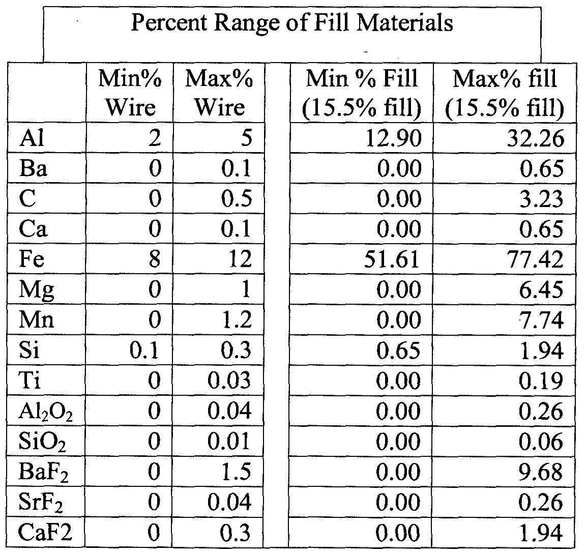
- the consumable electrode 100 can have fill materials as shown in Table 1. :
- the first column of Table 1 has an exemplary list of fill materials that can be used in electrodes that are consistent with the present invention. Of course, other materials can be used without departing from the sprit of the invention.
- the next two columns show the minimum and maximum percentage by weight of the wire (electrode) of each of the fill materials. As indicated by the 0% in the Min% column, not all the listed materials are necessarily present in every embodiment of the present invention. However, in some exemplary embodiments of the invention, the combination of the fill materials makes up approximately 15.5% by weight of the electrode 100. In the exemplary embodiments disclosed in Table 1 , the last two columns show the minimum and maximum percentage of each fill material as a percentage by weight of the total fill material.
- Table 2 shows the chemistry of an exemplary embodiment of the electrode 100.
- the "Fill” column shows the percentage by weight of the total fill material with the fill materials making up about 15.5% by weight of the electrode 100.
- the next two columns show a variance (i.e., the minimum percentage and the maximum percentage) as percent by weight of the wire (electrode) of each fill material in exemplary embodiments of the invention.
- the percentage of fill materials in these embodiments can range from about 14% to about 17%
- the consumable electrode 100 may be used in a GMAW system or a FCAW-G system such as that illustrated in Figure 1.
- the classification of whether electrode 00 is metal cored electrode or a flux cored electrode will depend on the amount of flux material 140 in the core 120.
- the electrode 100 is designed for reduced slag formation. Therefore, in some applications, there can be a greater risk of atmospheric nitrogen being transferred to the weld puddle 45 and thus porosity of the weld bead. Accordingly, consistent with the present invention, the consumable electrode 100 may be designed to be used with shielding gas 70 as shown in Figure 1 to provide additional porosity protection.
- the shielding gas 70 displaces the atmospheric nitrogen and oxygen around the arc 30 and weld puddle 45 by forming an envelope around them.
- the shielding gas 70 can be argon, helium, carbon dioxide, or any other inert gas or any blend thereof.
- the shielding gas 70 may be a combination of carbon dioxide and argon in which the concentration of carbon dioxide in the argon ranges from 10% to 25%.
- the GMAW or FCAW-G system can be set up as direct current electrode negative (DCEN).
- DCEN direct current electrode positive
- the DCEN method By using the DCEN method, there is minimal penetration, i.e., no keyhole effect, but the weld strength is not compromised. Because there is no keyhole effect, there is decreased interaction with the zinc coating and less risk of porosity.
- exemplary embodiments of the invention are capable of producing sound welds on galvanized metal at high travel speeds, e.g., 40 in/minute or higher.
- welds formed with a consumable electrode that is consistent with the present invention can achieve a tensile strength of greater than 700 M Pa, which matches high strength automotive sheet metal.
Landscapes
- Engineering & Computer Science (AREA)
- Mechanical Engineering (AREA)
- Nonmetallic Welding Materials (AREA)
- Arc Welding In General (AREA)
Abstract
Description

Claims
Priority Applications (2)
| Application Number | Priority Date | Filing Date | Title |
|---|---|---|---|
| CN201480026602.2A CN105189031A (en) | 2013-03-13 | 2014-03-07 | Consumable for specially coated metals |
| BR112015022502A BR112015022502A2 (en) | 2013-03-13 | 2014-03-07 | consumable for specially coated metals |
Applications Claiming Priority (2)
| Application Number | Priority Date | Filing Date | Title |
|---|---|---|---|
| US13/798,398 | 2013-03-13 | ||
| US13/798,398 US20140263259A1 (en) | 2013-03-13 | 2013-03-13 | Consumable for specially coated metals |
Publications (1)
| Publication Number | Publication Date |
|---|---|
| WO2014140708A1 true WO2014140708A1 (en) | 2014-09-18 |
Family
ID=50624860
Family Applications (1)
| Application Number | Title | Priority Date | Filing Date |
|---|---|---|---|
| PCT/IB2014/000256 Ceased WO2014140708A1 (en) | 2013-03-13 | 2014-03-07 | Consumable for specially coated metals |
Country Status (5)
| Country | Link |
|---|---|
| US (1) | US20140263259A1 (en) |
| CN (1) | CN105189031A (en) |
| BR (1) | BR112015022502A2 (en) |
| DE (1) | DE202014010582U1 (en) |
| WO (1) | WO2014140708A1 (en) |
Cited By (1)
| Publication number | Priority date | Publication date | Assignee | Title |
|---|---|---|---|---|
| KR20210145801A (en) * | 2019-05-09 | 2021-12-02 | 가부시키가이샤 고베 세이코쇼 | Flux Cored Wire, Welding Method and Welding Metal |
Families Citing this family (10)
| Publication number | Priority date | Publication date | Assignee | Title |
|---|---|---|---|---|
| US9821414B2 (en) | 2013-01-31 | 2017-11-21 | Siemens Energy, Inc. | Welding electrode |
| US10052706B2 (en) | 2014-04-04 | 2018-08-21 | Lincoln Global, Inc. | Method and system to use AC welding waveform and enhanced consumable to improve welding of galvanized workpiece |
| US10279435B2 (en) * | 2014-06-11 | 2019-05-07 | Lincoln Global, Inc. | Stick electrode |
| WO2016200560A1 (en) * | 2015-06-08 | 2016-12-15 | Siemens Energy, Inc. | Welding electrode |
| WO2017151737A1 (en) | 2016-03-03 | 2017-09-08 | H.C. Starck Inc. | Fabricaton of metallic parts by additive manufacturing |
| US11247291B2 (en) | 2016-11-16 | 2022-02-15 | Lincoln Global, Inc. | Welding electrode wires having alkaline earth metals |
| US10668572B2 (en) * | 2016-11-16 | 2020-06-02 | Lincoln Global, Inc. | Welding electrode wires having alkaline earth metals |
| US11426824B2 (en) * | 2017-09-29 | 2022-08-30 | Lincoln Global, Inc. | Aluminum-containing welding electrode |
| US11529697B2 (en) * | 2017-09-29 | 2022-12-20 | Lincoln Global, Inc. | Additive manufacturing using aluminum-containing wire |
| CN110497115B (en) * | 2018-05-16 | 2022-08-09 | 林肯环球股份有限公司 | Welding electrode wire with alkaline earth metal |
Citations (6)
| Publication number | Priority date | Publication date | Assignee | Title |
|---|---|---|---|---|
| US3488469A (en) * | 1968-03-08 | 1970-01-06 | Lincoln Electric Co | High impact cored welding electrode |
| US3947655A (en) * | 1974-05-15 | 1976-03-30 | The Lincoln Electric Company | Cored type electrode welding |
| JPS5548479A (en) * | 1978-09-29 | 1980-04-07 | Mitsubishi Electric Corp | Arc welding method |
| US4584459A (en) * | 1985-02-08 | 1986-04-22 | Teledyne Industries, Inc. | Spray transfer self-shielded tubular composite hard surfacing electrode |
| US20110297658A1 (en) * | 2009-01-13 | 2011-12-08 | Lincoln Global, Inc. | Method and system to start and use combination filler wire feed and high intensity energy source for welding |
| US20120205346A1 (en) * | 2009-10-21 | 2012-08-16 | Illinois Tool Works Inc. | Welding wire, usage of welding wire and method of manufacturing power tower |
Family Cites Families (9)
| Publication number | Priority date | Publication date | Assignee | Title |
|---|---|---|---|---|
| JP3513380B2 (en) * | 1998-01-26 | 2004-03-31 | 株式会社神戸製鋼所 | Carbon dioxide arc welding flux cored wire for DC positive polarity and welding method |
| JP3513382B2 (en) * | 1998-02-23 | 2004-03-31 | 株式会社神戸製鋼所 | Arc welding method for galvanized steel sheet |
| JP3511366B2 (en) * | 1998-09-09 | 2004-03-29 | 株式会社神戸製鋼所 | Flux-cored wire for gas-shielded arc welding for galvanized steel sheet welding |
| US7161109B2 (en) * | 2003-08-18 | 2007-01-09 | Praxair Technology, Inc. | Gas metal arc welding of coated steels and shielding gas therefor |
| US20060144836A1 (en) * | 2005-01-03 | 2006-07-06 | Lincoln Global, Inc. | Cored electrode for reducing diffusible hydrogen |
| US7678203B2 (en) * | 2005-03-04 | 2010-03-16 | Lincoln Global, Inc. | Welding flux |
| US7829820B2 (en) * | 2005-04-05 | 2010-11-09 | Lincoln Global, Inc. | Flux cored electrode with fluorine |
| US7812284B2 (en) * | 2005-07-12 | 2010-10-12 | Lincoln Global, Inc. | Barium and lithium ratio for flux cored electrode |
| CN102873468B (en) * | 2012-09-18 | 2014-10-01 | 武汉铁锚焊接材料股份有限公司 | A high-speed flat fillet welding flux-cored wire and its preparation and application |
-
2013
- 2013-03-13 US US13/798,398 patent/US20140263259A1/en not_active Abandoned
-
2014
- 2014-03-07 DE DE202014010582.0U patent/DE202014010582U1/en not_active Expired - Lifetime
- 2014-03-07 WO PCT/IB2014/000256 patent/WO2014140708A1/en not_active Ceased
- 2014-03-07 BR BR112015022502A patent/BR112015022502A2/en not_active IP Right Cessation
- 2014-03-07 CN CN201480026602.2A patent/CN105189031A/en active Pending
Patent Citations (6)
| Publication number | Priority date | Publication date | Assignee | Title |
|---|---|---|---|---|
| US3488469A (en) * | 1968-03-08 | 1970-01-06 | Lincoln Electric Co | High impact cored welding electrode |
| US3947655A (en) * | 1974-05-15 | 1976-03-30 | The Lincoln Electric Company | Cored type electrode welding |
| JPS5548479A (en) * | 1978-09-29 | 1980-04-07 | Mitsubishi Electric Corp | Arc welding method |
| US4584459A (en) * | 1985-02-08 | 1986-04-22 | Teledyne Industries, Inc. | Spray transfer self-shielded tubular composite hard surfacing electrode |
| US20110297658A1 (en) * | 2009-01-13 | 2011-12-08 | Lincoln Global, Inc. | Method and system to start and use combination filler wire feed and high intensity energy source for welding |
| US20120205346A1 (en) * | 2009-10-21 | 2012-08-16 | Illinois Tool Works Inc. | Welding wire, usage of welding wire and method of manufacturing power tower |
Cited By (3)
| Publication number | Priority date | Publication date | Assignee | Title |
|---|---|---|---|---|
| KR20210145801A (en) * | 2019-05-09 | 2021-12-02 | 가부시키가이샤 고베 세이코쇼 | Flux Cored Wire, Welding Method and Welding Metal |
| EP3967445A4 (en) * | 2019-05-09 | 2023-01-18 | Kabushiki Kaisha Kobe Seiko Sho (Kobe Steel, Ltd.) | Flux-cored wire, welding method, and weld metal |
| KR102647971B1 (en) * | 2019-05-09 | 2024-03-14 | 가부시키가이샤 고베 세이코쇼 | Flux cored wire, welding methods and weld metals |
Also Published As
| Publication number | Publication date |
|---|---|
| BR112015022502A2 (en) | 2017-07-18 |
| CN105189031A (en) | 2015-12-23 |
| US20140263259A1 (en) | 2014-09-18 |
| DE202014010582U1 (en) | 2016-02-18 |
Similar Documents
| Publication | Publication Date | Title |
|---|---|---|
| WO2014140708A1 (en) | Consumable for specially coated metals | |
| KR102210291B1 (en) | A tubular welding wire | |
| US9199341B2 (en) | Systems and methods for welding electrodes | |
| EP3175947B1 (en) | Methods for welding zinc-coated workpieces | |
| CA2937560C (en) | Systems and methods for welding wires for welding zinc-coated workpieces | |
| KR20140131996A (en) | Welding wire electrode, welding method and welding system | |
| US20140061179A1 (en) | Systems and methods for welding electrodes | |
| US11697171B2 (en) | Systems and methods for welding zinc-coated workpieces | |
| US20180133844A1 (en) | Welding electrode wires having alkaline earth metals | |
| EP2945773B1 (en) | Method of manufacturing a tubular metal-cored welding wire | |
| JP3210609U (en) | Consumable electrode for special coated metal | |
| EP3666452A1 (en) | Improved crack-resistant wire electrode containing added sulfur source and magnesium oxide | |
| JP2015136720A (en) | Two electrode horizontal fillet gas shield arc welding method | |
| JPH11226735A (en) | Gas shielded arc welding method | |
| JP3947422B2 (en) | MIG welding method of titanium or titanium alloy | |
| JP2003320477A (en) | Titanium or titanium alloy MIG welding wire excellent in arc stability and MIG welding method of titanium or titanium alloy using the wire | |
| JP2015136719A (en) | Two electrode horizontal fillet gas shield arc welding method | |
| JP2015073997A (en) | Two-electrode horizontal fillet gas shielded arc welding method |
Legal Events
| Date | Code | Title | Description |
|---|---|---|---|
| WWE | Wipo information: entry into national phase |
Ref document number: 201480026602.2 Country of ref document: CN |
|
| 121 | Ep: the epo has been informed by wipo that ep was designated in this application |
Ref document number: 14720215 Country of ref document: EP Kind code of ref document: A1 |
|
| ENP | Entry into the national phase |
Ref document number: 2015600139 Country of ref document: JP Kind code of ref document: A |
|
| NENP | Non-entry into the national phase |
Ref country code: DE |
|
| REG | Reference to national code |
Ref country code: BR Ref legal event code: B01A Ref document number: 112015022502 Country of ref document: BR |
|
| 122 | Ep: pct application non-entry in european phase |
Ref document number: 14720215 Country of ref document: EP Kind code of ref document: A1 |
|
| NENP | Non-entry into the national phase |
Ref country code: JP |
|
| ENP | Entry into the national phase |
Ref document number: 112015022502 Country of ref document: BR Kind code of ref document: A2 Effective date: 20150911 |