WO2014136363A1 - 製造方法および製造装置 - Google Patents
製造方法および製造装置 Download PDFInfo
- Publication number
- WO2014136363A1 WO2014136363A1 PCT/JP2013/085000 JP2013085000W WO2014136363A1 WO 2014136363 A1 WO2014136363 A1 WO 2014136363A1 JP 2013085000 W JP2013085000 W JP 2013085000W WO 2014136363 A1 WO2014136363 A1 WO 2014136363A1
- Authority
- WO
- WIPO (PCT)
- Prior art keywords
- laminated
- manufacturing
- module
- positioning
- manufacturing apparatus
- Prior art date
- Legal status (The legal status is an assumption and is not a legal conclusion. Google has not performed a legal analysis and makes no representation as to the accuracy of the status listed.)
- Ceased
Links
Images












Classifications
-
- H—ELECTRICITY
- H01—ELECTRIC ELEMENTS
- H01M—PROCESSES OR MEANS, e.g. BATTERIES, FOR THE DIRECT CONVERSION OF CHEMICAL ENERGY INTO ELECTRICAL ENERGY
- H01M8/00—Fuel cells; Manufacture thereof
- H01M8/24—Grouping of fuel cells, e.g. stacking of fuel cells
- H01M8/2465—Details of groupings of fuel cells
- H01M8/247—Arrangements for tightening a stack, for accommodation of a stack in a tank or for assembling different tanks
- H01M8/248—Means for compression of the fuel cell stacks
-
- B—PERFORMING OPERATIONS; TRANSPORTING
- B32—LAYERED PRODUCTS
- B32B—LAYERED PRODUCTS, i.e. PRODUCTS BUILT-UP OF STRATA OF FLAT OR NON-FLAT, e.g. CELLULAR OR HONEYCOMB, FORM
- B32B38/00—Ancillary operations in connection with laminating processes
- B32B38/18—Handling of layers or the laminate
- B32B38/1808—Handling of layers or the laminate characterised by the laying up of the layers
-
- H—ELECTRICITY
- H01—ELECTRIC ELEMENTS
- H01M—PROCESSES OR MEANS, e.g. BATTERIES, FOR THE DIRECT CONVERSION OF CHEMICAL ENERGY INTO ELECTRICAL ENERGY
- H01M8/00—Fuel cells; Manufacture thereof
- H01M8/24—Grouping of fuel cells, e.g. stacking of fuel cells
- H01M8/2404—Processes or apparatus for grouping fuel cells
-
- H—ELECTRICITY
- H01—ELECTRIC ELEMENTS
- H01M—PROCESSES OR MEANS, e.g. BATTERIES, FOR THE DIRECT CONVERSION OF CHEMICAL ENERGY INTO ELECTRICAL ENERGY
- H01M8/00—Fuel cells; Manufacture thereof
- H01M8/24—Grouping of fuel cells, e.g. stacking of fuel cells
- H01M8/2465—Details of groupings of fuel cells
- H01M8/247—Arrangements for tightening a stack, for accommodation of a stack in a tank or for assembling different tanks
-
- B—PERFORMING OPERATIONS; TRANSPORTING
- B32—LAYERED PRODUCTS
- B32B—LAYERED PRODUCTS, i.e. PRODUCTS BUILT-UP OF STRATA OF FLAT OR NON-FLAT, e.g. CELLULAR OR HONEYCOMB, FORM
- B32B2457/00—Electrical equipment
- B32B2457/18—Fuel cells
-
- H—ELECTRICITY
- H01—ELECTRIC ELEMENTS
- H01M—PROCESSES OR MEANS, e.g. BATTERIES, FOR THE DIRECT CONVERSION OF CHEMICAL ENERGY INTO ELECTRICAL ENERGY
- H01M8/00—Fuel cells; Manufacture thereof
- H01M8/10—Fuel cells with solid electrolytes
- H01M2008/1095—Fuel cells with polymeric electrolytes
-
- Y—GENERAL TAGGING OF NEW TECHNOLOGICAL DEVELOPMENTS; GENERAL TAGGING OF CROSS-SECTIONAL TECHNOLOGIES SPANNING OVER SEVERAL SECTIONS OF THE IPC; TECHNICAL SUBJECTS COVERED BY FORMER USPC CROSS-REFERENCE ART COLLECTIONS [XRACs] AND DIGESTS
- Y02—TECHNOLOGIES OR APPLICATIONS FOR MITIGATION OR ADAPTATION AGAINST CLIMATE CHANGE
- Y02E—REDUCTION OF GREENHOUSE GAS [GHG] EMISSIONS, RELATED TO ENERGY GENERATION, TRANSMISSION OR DISTRIBUTION
- Y02E60/00—Enabling technologies; Technologies with a potential or indirect contribution to GHG emissions mitigation
- Y02E60/30—Hydrogen technology
- Y02E60/50—Fuel cells
-
- Y—GENERAL TAGGING OF NEW TECHNOLOGICAL DEVELOPMENTS; GENERAL TAGGING OF CROSS-SECTIONAL TECHNOLOGIES SPANNING OVER SEVERAL SECTIONS OF THE IPC; TECHNICAL SUBJECTS COVERED BY FORMER USPC CROSS-REFERENCE ART COLLECTIONS [XRACs] AND DIGESTS
- Y02—TECHNOLOGIES OR APPLICATIONS FOR MITIGATION OR ADAPTATION AGAINST CLIMATE CHANGE
- Y02P—CLIMATE CHANGE MITIGATION TECHNOLOGIES IN THE PRODUCTION OR PROCESSING OF GOODS
- Y02P70/00—Climate change mitigation technologies in the production process for final industrial or consumer products
- Y02P70/50—Manufacturing or production processes characterised by the final manufactured product
Definitions
- the present invention relates to a manufacturing method and a manufacturing apparatus that embodies the manufacturing method.
- a fuel cell is configured by alternately laminating separators and membrane electrode assemblies. Since the fuel cell can obtain a high output according to the number of laminated layers of the separator and the membrane electrode assembly, it is desirable to increase the number of laminated layers.
- the positions of the separators to be stacked are relatively shifted, for example, the anode gas, cathode gas, and cooling water through-holes provided in the separator do not coincide with each other between the adjacent separators. Battery performance cannot be achieved.
- the two positioning holes provided in the laminated member are:
- the two positioning members are not smoothly inserted.
- the positioning hole of the laminated member and the tip of the positioning member interfere locally, and there is a possibility that the laminated member under load is deformed.
- the present invention has been made to solve the above-described problems, and an object of the present invention is to provide a manufacturing method capable of stacking with high positioning accuracy without deforming a stacked member and a manufacturing apparatus embodying the manufacturing method.
- the manufacturing method according to the present invention that achieves the above object is a manufacturing method in which a plurality of laminated members each formed in a plate shape are laminated and manufactured while being positioned on a surface orthogonal to the laminating direction.
- This manufacturing method has a guide process and a positioning process.
- the laminated member is moved while being guided in the laminating direction in a state in which the first reference surface along the laminating direction of the laminated member is along the first positioning member arranged in the laminating direction of the laminated member.
- the second reference surface along the stacking direction of the laminated member is arranged on the second positioning member arranged in parallel with the first positioning member while the laminated member is moving along the first positioning member. Position by abutting.
- the manufacturing apparatus that achieves the above object is a manufacturing apparatus that manufactures by laminating a plurality of laminated members each formed in a plate shape while positioning each other on a plane orthogonal to the laminating direction.
- the manufacturing apparatus includes a first positioning member, a second positioning member, a moving member, and a control unit.
- the first positioning member has a long shape and is disposed on the reference table.
- the second positioning member is disposed on the reference base in parallel with the longitudinal direction of the first positioning member, and has a long shape shorter than the first positioning member.
- the moving member moves the laminated member.
- the control unit controls the operation of the moving member, and moves the first reference surface along the stacking direction of the stacked member along the first positioning member, and the second reference surface along the stacking direction of the stacked member. Is positioned while being moved along the second positioning member.
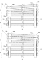
- FIG. 4 is a partial cross-sectional view taken along line 4-4 in FIG. 3, showing a state in which the module is inserted into the main pillar after being inserted into the main pillar in the manufacturing apparatus according to the first embodiment.
- FIG. 8 is a perspective view showing a state in which the steps shown in FIGS. 3 to 7 are repeated and all necessary modules are stacked in the manufacturing apparatus according to the first embodiment.
- the manufacturing apparatus which concerns on 1st Embodiment after pulling out a pillar space
- FIG. 10 is a perspective view showing various forms relating to the tip of the follower used in the steps shown in FIGS. 2 to 9 in the manufacturing apparatus according to the first embodiment. It is a perspective view which shows the various forms which position a module with respect to the main pillar with which the manufacturing apparatus which concerns on 1st Embodiment was equipped, and the follower pillar.
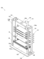
- FIG. 5 is a perspective view showing a state in which the module 10 is temporarily placed on all temporary placement spacers 141 in the manufacturing apparatus 100 and then the column interval adjusting jig 150 is inserted through the main pillar 131 and the secondary pillar 132.
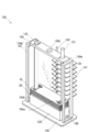
- FIG. 6 is a perspective view illustrating a state in which all modules 10 temporarily placed on the temporary placement spacer 141 are sequentially moved downward and stacked in the manufacturing apparatus 100.
- FIG. 7 is a perspective view showing a state in which all the modules 10 that have been temporarily placed on the temporary spacer 141 have been stacked in the manufacturing apparatus 100 by repeating the process shown in FIG. 6.
- FIG. 8 is a perspective view showing a state in which all the necessary modules 10 have been stacked in the manufacturing apparatus 100 by repeating the steps shown in FIGS.
- FIG. 9 is a perspective view showing a state in which the second end member 30 is stacked on the uppermost module 10 after the column interval adjusting jig 150 is pulled out in the manufacturing apparatus 100.
- FIG. 10 is a perspective view showing various forms related to the distal end portion of the follower pillar 132 used in the steps shown in FIGS. 2 to 9 in the manufacturing apparatus 100.
- FIG. 11 is a perspective view showing various forms for positioning the module 10 with respect to the main pillar 131 and the follower pillar 132 provided in the manufacturing apparatus 100.
- the member indicated by the broken line is in a state before operation, and the member indicated by the solid line is in operation or is in operation. The later state is shown.
- the module 10 corresponds to a laminated member. Specifically, the module 10 is configured, for example, by laminating a plurality of separators and membrane electrode assemblies (MEAs) used in the fuel cell 1 alternately.
- the module 10 is formed in a long plate shape.
- the module 10 includes a through hole corresponding to the cathode gas supply port 10c, the cooling fluid supply port 10d, and the anode gas supply port 10e at one end in the longitudinal direction.
- the module 10 includes through holes corresponding to the anode gas discharge port 10f, the cooling fluid discharge port 10g, and the cathode gas discharge port 10h at the other end in the longitudinal direction.
- the main column 131 is inserted into the cooling fluid supply port 10d, and the follower column 132 is inserted through the cooling fluid discharge port 10g.
- the main column 131 corresponds to a first positioning member.
- the sub pillar 132 corresponds to a second positioning member.
- the first end member 20 is inserted into the main pillar 131 and the sub pillar 132, and the first end member 20 is attached to the reference base 120. It is mounted (S101 in FIG. 1).
- the reference stand 120 of the manufacturing apparatus 100 is made of, for example, metal and is formed in a rectangular parallelepiped.
- the upper part of the reference table 120 is formed smoothly because the modules 10 are stacked via the first end member 20.
- the reference table 120 has round holes at both ends in the longitudinal direction of the upper part.
- a main pillar 131 and a follower pillar 132 are detachably inserted into a round hole provided in the reference table 120.
- the main column 131 has a long shape and is disposed on the reference table 120.
- the main column 131 has a cylindrical shape and has an outer peripheral surface that is formed smoothly.
- the sub pillar 132 is arranged on the reference base 120 in parallel with the longitudinal direction of the main pillar 131 and has a long shape shorter than the main pillar 131.
- the sub pillar 132 includes a tip portion 132a having a tapered shape and a base material portion 132b extending the tip portion 132a.
- the base portion 132b of the follower 132 has a smooth outer peripheral surface.
- the reference table 120 is fixed to the upper part of the support table 110.
- the support base 110 is made of, for example, metal and is formed in a plate shape.
- the first end member 20 of the fuel cell 1 sandwiches a plurality of stacked modules 10 with a second end member 30 described later.
- the first end member 20 is made of, for example, a metal, and an insulator is provided at a portion in contact with the module 10.
- the outer shape of the first end member 20 is the same as the outer shape of the module 10.
- the first end member 20 is formed in a rectangular plate shape, and has a through hole corresponding to the cathode gas supply port 20c, the cooling fluid supply port 20d, and the anode gas supply port 20e at one end in the longitudinal direction. .
- the first end member 20 includes a through hole corresponding to the anode gas discharge port 20f, the cooling fluid discharge port 20g, and the cathode gas discharge port 20h at the other end in the longitudinal direction.
- the main column 131 is inserted into the cooling fluid supply port 20d, and the follower column 132 is inserted through the cooling fluid discharge port 20g.
- a pair of handling hands 171 and 172 corresponding to the moving member are used for conveying the first end member 20 .
- the pair of handling hands 171 and 172 each sandwich the first end member 20.
- the handling hand 171 grasps one end of the first end member 20 in the longitudinal direction
- the handling hand 172 grasps the other end of the first end member 20 in the longitudinal direction.
- the pair of handling hands 171 and 172 are movable to arbitrary positions in the horizontal and vertical directions by a three-axis moving stage (not shown).
- the lowermost temporary spacer 141 located on the downstream side in the stacking direction of the modules 10 is rotated forward 180 degrees clockwise around the rotating portion 141a, thereby stacking the modules 10. Project into the area.
- the temporary spacer 141 corresponds to a temporary member.
- the module 10 is expressed as MOD (S102 in FIG. 1).
- a plurality of temporary spacers 141 of the manufacturing apparatus 100 are provided at regular intervals with respect to the support column 142.
- the temporary placement spacer 141 is formed in a plate shape so as to place the central portion of the module 10.
- the longitudinal dimension of the temporary spacer 141 is shorter than the longitudinal dimension of the module 10.
- the short-side dimension of the temporary spacer 141 is slightly longer than the short-side dimension of the module 10.
- the temporary spacer 141 is provided so as to be rotatable with respect to the support column 142 around a rotating portion 141a provided at one end thereof.
- a plurality of temporary spacers 141 provided on the support 142 are individually rotated.
- the support column 142 is disposed perpendicular to the support table 110 so as to be adjacent to the reference table 120.
- the module 10 is lowered and the first opening 10 a of the module 10 is inserted into the main pillar 131.
- the first opening 10a corresponds to, for example, the cooling fluid supply port 10d.
- the module 10 is lowered along the main column 131 in a state where the main column 131 is in contact with the first reference surface 10aa of the first opening 10a of the module 10.
- the first reference surface 10aa is an inner surface of the first opening 10a and is provided in a plane along the stacking direction of the modules 10 (S103 in FIG. 1).
- the module 10 is further lowered, and the second opening 10b of the module 10 is inserted into the follower column 132.
- the second opening 10b corresponds to, for example, the cooling fluid discharge port 10g.
- the module 10 is lowered along the follower column 132 in a state where the follower column 132 is in contact with the second reference surface 10bb of the second opening 10b of the module 10.
- the second reference surface 10bb is an inner surface of the second opening 10b and is provided in a plane along the stacking direction of the modules 10 (S104 in FIG. 1).
- the module 10 is further lowered and temporarily placed on the temporary placement spacer 141 (S105 in FIG. 1).
- a pair of handling hands 173 and 174 corresponding to moving members are used for conveying the module 10.
- the pair of handling hands 173 and 174 each sandwich the module 10.
- the handling hand 171 grasps one end of the module 10 in the longitudinal direction
- the handling hand 172 grasps the other end in the longitudinal direction of the module 10.
- the pair of handling hands 173 and 174 are movable to arbitrary positions in the horizontal and vertical directions by a three-axis moving stage (not shown).
- the controller 180 corresponds to a control unit, controls the operation of the handling hands 173 and 174, and moves the first reference plane 10aa along the stacking direction of the modules 10 along the main pillar 131.
- the second reference surface 10bb along the stacking direction of 10 is positioned along the follower pillar 132 while being moved.
- the controller 180 includes a ROM, a CPU, and a RAM.
- ROM Read Only Memory
- a CPU Central Processing Unit
- a RAM Random Access Memory
- the area indicated by A in FIG. 4A corresponds to the guide unit 101.
- the module 10 is lowered so as to approach the main pillar 131 while being inclined downward from the main pillar 131 toward the sub pillar 132.
- the module 10 is inclined in the counterclockwise direction in the drawing when the first opening 10 a is brought into contact with the main pillar 131.
- the module 10 moves along the main pillar 131 in a state where the first reference surface 10aa of the first opening 10a is in contact with the main pillar 131, the module 10 is adjusted from an inclined state to a horizontal state.
- the thickness of the module 10 increases, the area where the first reference surface 10aa of the first opening 10a contacts the main pillar 131 increases, and the inclination of the module 10 can be easily adjusted.
- the area indicated by B in FIG. 4A corresponds to the positioning unit 102.
- the second opening 10 b of the module 10 is inserted into the follower 132.
- the sub pillar 132 includes a tip portion 132a having a tapered shape, and a base material portion 132b having a cylindrical shape extending from the tip portion 132a.
- the tip of the tapered shape is in the process of moving while contacting the front end 132a of the follower pillar 132. Since it is guided to the portion 132a, the angle error can be eliminated.
- the module 10 shown in FIG. 4B is so approached to the main column 131 that it is inclined downward from the follower column 132 toward the main column 131 in the guide portion 101. Lower.
- the module 10 is inclined in the clockwise direction in the drawing when the first opening 10a abuts the main pillar 131.
- the module 10 extends along the main column 131 in a state where the first reference surface 10aa of the first opening 10a is in contact with the main column 131. Since it moves, it is adjusted from an inclined state to a horizontal state.
- the second opening 10b of the module 10 is inserted into the follower pillar 132.
- the tip of the tapered shape is in the process of moving while contacting the front end 132a of the follower pillar 132. Since it is guided to the portion 132a, the angle error can be eliminated.
- the modules 10 are temporarily placed in order. That is, the steps S102 to S105 in FIG. 1 are repeated until the module 10 is temporarily placed in all the temporarily placeable spacers (S106 in FIG. 1).
- the column interval adjusting jig 150 for positioning the relative position of the main column 131 and the sub column 132 is inserted into the main column 131 and the sub column 132, respectively.
- the column interval adjusting jig 150 is installed on top of the pair of reference side columns 161 and 162 provided close to both ends in the longitudinal direction of the reference table 120 (S107 in FIG. 1).
- the column interval adjusting jig 150 of the manufacturing apparatus 100 corresponds to a holding member.
- the column interval adjusting jig 150 is made of, for example, metal and is formed in a plate shape. At both ends in the longitudinal direction of the column interval adjusting jig 150, there are provided a first reference hole 150a and a second reference hole 150b formed of through holes.
- a first reference hole 150a and a second reference hole 150b formed of through holes.
- the pair of reference side columns 161 and 162 are arranged on the support base 110 so as to be close to both ends of the reference base 120 in the longitudinal direction.
- the pair of reference side columns 161 and 162 are made of, for example, metal and are formed in a plate shape with a large opening inside.
- a pair of handling hands 175 and 176 corresponding to moving members are used for transporting the column interval adjusting jig 150.
- the pair of handling hands 175 and 176 respectively hold the column interval adjusting jig 150.
- the handling hand 171 grasps one end in the longitudinal direction of the column interval adjusting jig 150, and the handling hand 172 grasps the other end in the longitudinal direction of the column interval adjusting jig 150.
- the pair of handling hands 175 and 176 are movable to arbitrary positions in the horizontal and vertical directions by a three-axis moving stage (not shown).
- the temporary spacer 141 temporarily placing the module 10 is 180 degrees centering on the rotating portion 141a. Reverse counterclockwise. As a result, the temporary spacer 141 is retracted from the stacked region of the module 10 (S108 in FIG. 1). Next, the module 10 in which the temporary spacer 141 is retracted and moved is moved downward and stacked (S109 in FIG. 1).
- the second end member 30 is inserted into the main column 131 and the sub column 132, respectively, and the second end member 30 is stacked on the uppermost module 10 (S113 in FIG. 1).
- the second end member 30 of the fuel cell 1 sandwiches a plurality of stacked modules 10 with the first end member 20.
- the second end member 30 is made of, for example, a metal, and an insulator is provided at a portion in contact with the module 10.
- the outer shape of the second end member 30 is the same as the outer shape of the module 10.
- the second end member 30 is formed in a long plate shape, and has a through hole corresponding to the cathode gas supply port 30c, the cooling fluid supply port 30d, and the anode gas supply port 30e at one end in the longitudinal direction. .
- the second end member 30 includes a through hole corresponding to the anode gas discharge port 30f, the cooling fluid discharge port 30g, and the cathode gas discharge port 30h at the other end in the longitudinal direction.
- the main column 131 is inserted into the cooling fluid supply port 30d, and the follower column 132 is inserted through the cooling fluid discharge port 30g.
- a pair of handling hands 171 and 172 are used for transporting the second end member 30.
- the pair of handling hands 171 and 172 each sandwich the second end member 30.
- the handling hand 171 grasps one end in the longitudinal direction of the second end member 30, and the handling hand 172 grasps the other end in the longitudinal direction of the second end member 30.
- the pair of handling hands 171 and 172 are movable to arbitrary positions in the horizontal and vertical directions by a three-axis moving stage (not shown).
- the tip of the follower column 132 used in the steps shown in FIGS. 2 to 9 can have various configurations.
- the tip portion 132a may be formed in a truncated cone shape.
- the tip portion 132a shown in FIG. 10A corresponds to the tip portion 132a shown in FIGS.
- the tip end portion 132c may be formed in a conical shape.
- the follower column 132 includes a tip portion 132c formed in a truncated cone shape, and a base material portion 132d that extends from the tip portion 132c and has a cylindrical shape.
- the tip end portion 132e may be formed in a multistage shape.
- the sub pillar 132 includes a tip portion 132e formed in a multi-stage shape, and a base material portion 132f that extends from the tip portion 132e and has a cylindrical shape.
- the tip portion 132g having a truncated cone shape may be formed so as to be separable from the base material portion 132h having a cylindrical shape.
- a screw provided protruding from the lower portion of the tip end portion 132g shown in FIG. 10D is screwed into a screw groove provided in the upper surface of the base material portion 132h.
- the main pillar 131 and the secondary pillar 132 used in the steps shown in FIGS. 2 to 9 can position the modules 10 formed in various shapes as shown in FIG.
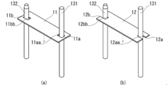
- the main pillar 131 is formed with respect to the first opening portion 11a and the second opening portion 11b opened near both ends in the longitudinal direction of the module 11.
- And follower pillars 132 are inserted and moved respectively.
- the first reference surface 11aa is an inner surface of the first opening 11a and is provided in a plane along the stacking direction of the modules 11.
- the second reference surface 11bb is an inner surface of the second opening 11b and is provided in a plane along the stacking direction of the modules 11.
- the module 12 having a form corresponding to FIG. 11B may be used.
- the main pillar 131 and the secondary pillar 132 are arranged along the first notch 12a and the second notch 12b formed by notching the outer periphery of both ends of the module 12 in the longitudinal direction. Move them.
- the first reference surface 12aa is an inner surface of the first cutout portion 12a and is provided in a surface along the stacking direction of the modules 12.
- the second reference surface 12bb is an inner surface of the second notch 12b and is provided in a surface along the stacking direction of the modules 12.
- the manufacturing method according to the first embodiment described above and the manufacturing apparatus 100 that embodies the manufacturing method have the following operational effects.
- the manufacturing method according to the first embodiment is a manufacturing method in which a plurality of modules 10 each formed in a plate shape are stacked and manufactured while being positioned on a plane orthogonal to the stacking direction.
- This manufacturing method has a guide process and a positioning process.
- the module 10 is moved while being guided in the stacking direction in a state where the first reference surface 10aa along the stacking direction of the module 10 is along the main pillar 131 disposed toward the stacking direction of the module 10. .
- the positioning step while the module 10 is moving along the main pillar 131, the second reference surface 10 bb along the stacking direction of the modules 10 is brought into contact with the sub pillar 132 arranged in parallel with the main pillar 131. To position.
- the manufacturing apparatus 100 stacks and manufactures a plurality of modules 10 each formed in a plate shape while positioning each other on a plane orthogonal to the stacking direction.
- the manufacturing apparatus 100 includes a main pillar 131, a follower pillar 132, handling hands 173 and 174, and a controller 180.
- the main column 131 has a long shape and is disposed on the reference table 120.
- the sub pillar 132 is arranged on the reference base 120 in parallel with the longitudinal direction of the main pillar 131 and has a long shape shorter than the main pillar 131.
- the handling hands 173 and 174 move the module 10.
- the controller 180 controls the operations of the handling hands 173 and 174 and moves along the stacking direction of the module 10 while moving the first reference surface 10aa along the stacking direction of the module 10 along the main pillar 131.
- the second reference surface 10bb is positioned while being moved along the sub pillar 132.
- the second reference surface 10bb along the stacking direction of the modules 10 is parallel to the main column 131 while the module 10 is moving along the main column 131. Then, the positioning is performed by contacting the follower pillar 132 arranged in this manner. According to such a manufacturing method and manufacturing apparatus 100, the modules 10 can be stacked with high accuracy without being deformed.
- the positioning of the module 10 is performed with a simple configuration using the main pillar 131 and the secondary pillar 132, and complicated mechanisms and sensors are not required. Can do.
- the manufacturing method and the manufacturing apparatus 100 configured as described above, since the module 10 is not deformed, the production is not interrupted due to the deformation of the module 10, and the manufacturing efficiency can be improved.
- first reference surface 10aa and the second reference surface 10bb are respectively provided on the inner surfaces of the first opening 10a and the second opening 10b formed in the module 10, and the main pillar 131 and the secondary pillar 132 are provided in the first opening. It is good also as a structure penetrated to 10a and the 2nd opening part 10b, respectively.
- the cooling fluid supply port of the module 10 is used as the first opening 10a
- the first reference surface 10aa is provided on the inner surface of the cooling fluid supply port
- the cooling fluid discharge port of the module 10 is used as the second opening 10b. If the second reference surface 10bb is provided on the inner surface of the cooling fluid discharge port, there is no need to provide an opening.
- main pillar 131 may be configured such that the module 10 is rotatable in a direction intersecting the stacking direction with reference to the abutted first reference surface 10aa.
- the angle error is reduced by rotating the module 10 with respect to the first reference plane 10aa. Can be resolved.
- the main column 131 may be formed in a cylindrical shape or a polygonal column shape, and the first reference surface 10aa may be composed of three continuous surfaces.
- the main column 131 allows the module 10 to rotate in a state where the outer peripheral surfaces are in contact with three continuous surfaces.
- the module 10 is configured with a simple configuration in which the outer periphery of the main column 131 formed in a cylindrical shape or a polygonal column shape is brought into contact with the first reference surface 10aa including three continuous surfaces. Positioning can be performed with respect to the main column 131 by eliminating the angle error.
- the distal end of the follower pillar 132 may be configured to recede by more than the thickness of the module 10 in the stacking direction of the module 10 from the distal end of the main pillar 131. That is, in the manufacturing apparatus 100, the sub pillar 132 may be configured to be shorter than the main pillar 131 by the thickness of the module 10 or more.
- the secondary pillar 132 is brought into contact with the second reference surface 10bb of the module 10. be able to. Therefore, it is possible to reliably prevent the module 10 from being deformed.
- the follower column 132 may have a configuration in which a tip portion having a tapered shape is provided at the tip thereof.
- the module 10 that is in contact with the main pillar 131 moves while being in contact with the distal end portion 132a of the follower pillar 132 even when an angular error occurs in the direction intersecting the stacking direction.
- the angle error can be eliminated by being guided to the tapered tip portion 132a.
- tip 132a of the follower 132 may be configured to be inclined linearly outward along the stacking direction of the modules 10.
- the module 10 moves in contact with the tip portion 132a inclined in a tapered shape in the process of moving.
- the angle error can be eliminated smoothly. Therefore, the interference between the module 10 and the follower pillar 132 can be suppressed, and the stress applied to the module 10 can be greatly reduced.
- the tip 132e of the follower pillar 132 may have a multi-stage shape with a plurality of refracting parts or bent parts.
- the module 10 moves in contact with the tip portion 132e formed in a multistage shape in the process of moving.
- the angle error can be eliminated step by step. Therefore, the interference between the module 10 and the follower pillar 132 can be suppressed, and the stress applied to the module 10 can be greatly reduced.
- tip 132g of the follower 132 may be configured to be separable.
- the follower pillar 132 may include a base material part 132b having a columnar shape or a polygonal prism shape with the tip part 132a extending, and the entire length of the base material part 132b may be longer than the thickness of the module 10.
- the module 10 inserted through the follower pillar 132 can be sufficiently positioned at the base portion 132b of the follower pillar 132.
- the follower pillar 132 and the main pillar 131 may be configured to be stacked in the direction opposite to the stacking direction of the modules 10.
- the follower column 132 when the number of stacked modules 10 is increased, it can be easily handled by stacking the follower pillar 132 and the main pillar 131.
- the follower column 132 is stacked by screwing the base member portion 132h having a screw thread in the lower part thereof with respect to the substrate member 132h shown in FIG. .
- the main pillar 131 may have the same configuration as the follower pillar 132.
- the manufacturing apparatus 100 is connected to the main pillar 131 and the sub pillar 132 after the module 10 is inserted and before the stacking, and the column interval adjusting jig that holds and positions the main pillar 131 and the sub pillar 132. 150 may be further included.
- the positions of the main pillar 131 and the follower pillar 132 are positioned using the pillar interval adjusting jig 150. Lamination can be performed with higher positioning accuracy.
- the temporary placement process which temporarily places the several module 10 in the state spaced apart from each other along the lamination direction using the several temporary placement spacer 141.
- the plurality of modules 10 are temporarily placed in order from the temporary placement spacer 141 located on the downstream side in the stacking direction of the modules 10 in the temporary placement step.
- the main pillar 131 and the secondary pillar 132 are held in a positioned state by the holding step.
- the temporary placement step the temporary placement of the modules 10 is released in order from the module 10 located downstream in the stacking direction of the modules 10 and the movement of the modules 10 is resumed.
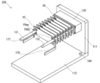
- FIG. 12 is a perspective view showing a state in which the module 10 is inserted and temporarily placed in the main pillar 131 and the secondary pillar 132 arranged in parallel in the manufacturing apparatus 200.
- the manufacturing method and the manufacturing apparatus 200 according to the modification of the first embodiment are different from the configuration of the manufacturing method and the manufacturing apparatus 100 according to the first embodiment described above in that the module 10 is suspended and moved.
- the manufacturing apparatus 200 shown in FIG. 12 holds the reference table 120 by the side plate 111 from the side with the reference table 120 rotated 90 ° clockwise from the state shown in FIG.
- the lower part of the side plate 111 is joined to the support base 112.
- the main pillar 131 and the follower pillar 132 inserted through the reference table 120 are also arranged in parallel in a state of being rotated 90 ° clockwise from the state shown in FIG.
- the module 10 conveyed using handling hands 177 and 178 corresponding to moving members is inserted into the main pillar 131 and the sub pillar 132, and the module 10 is suspended and moved.
- the handling hands 177 and 178 temporarily place the adjacent modules 10 apart from each other.
- the second end member 30 is inserted through the main pillar 131 and the sub pillar 132, and the plurality of modules 10 are brought into close contact with each other and stacked.
- the guide process and the guide unit are moved by suspending the module 10 from the main pillar 131 that has a long shape and is arranged horizontally. Further, the positioning step and the positioning portion suspend and move the module 10 with respect to the follower pillar 132 that is formed in a long shape and is horizontally disposed.
- the guide step and the positioning step may be configured to move adjacent modules 10 in a separated state.
- FIG. 13 is a flowchart illustrating a method for applying a load to the stacked modules 10 in the method for manufacturing the module 10 using the manufacturing apparatus 300.
- FIG. 14 is a perspective view showing a state in which the load applying member 310 is placed on the second end member 30, the column interval adjusting jig 150 is attached, and the module 10 is urged in the manufacturing apparatus 300.
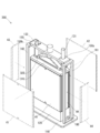
- FIG. 15 is a perspective view showing a state in which the exterior member is attached to the module 10 or the like while the module 10 is urged by the load applying member 310 in the manufacturing apparatus 300.
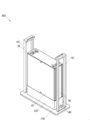
- FIG. 16 is a perspective view showing a state after the pressing member 320, the column interval adjusting jig 150, and the load applying member 310 are removed in the manufacturing apparatus 300.
- the member indicated by the broken line is in a state before operation, and the member indicated by the solid line is in operation or in operation. The later state is shown.
- the configuration of the manufacturing method and the manufacturing apparatus 300 according to the second embodiment is different from the configuration of the manufacturing method and the manufacturing apparatus 100 according to the first embodiment described above in that the load is applied to the stacked modules 10.
- the load adding step in the manufacturing method corresponds to the load adding portion of the manufacturing apparatus 300.
- a load is applied to the module 10 in which a plurality of layers are stacked as shown in FIG. 14.
- the load applying member 310 is inserted into the main pillar 131 and the follower pillar 132, and placed on the second end member 30.
- the load applying member 310 is made of, for example, metal and is formed in a plate shape.
- a first hole 310a and a second hole 310b are inserted through the main pillar 131 and the follower pillar 132 (S201 in FIG. 13).
- the column interval adjusting jig 150 is inserted into the main column 131 and the sub column 132, and is installed on the upper part of the pair of reference side columns 161 and 162 (S202 in FIG. 13).
- the pressing member 320 is inserted into the insertion hole 150 c opened in the center of the column interval adjusting jig 150 to press the load applying member 310.
- the pressing member 320 is made of, for example, metal and has a cylindrical shape (S203 in FIG. 13).
- the load applying jig 310 urges the module 10 that is stacked in plural via the second end member 30 (S204 in FIG. 13).
- the exterior member is attached to the plurality of stacked modules 10 and the like in a state where the plurality of stacked modules 10 are pressed by the load applying member 310 as shown in FIG.
- the exterior member composed of the first main plate 41, the second main plate 42, the first side plate 43, and the second side plate 44 is attached to the first end member 20 and the second end member 30 using screws (not shown). Screw into the threaded groove provided in The first main plate 41, the second main plate 42, the first side plate 43, and the second side plate 44 are each made of a metal plate (S205 in FIG. 13).
- the pressing member 320 is pulled out from the insertion hole 150c of the column interval adjusting jig 150 and removed from the process shown in FIG. 15 (S206 in FIG. 13).
- the column interval adjusting jig 150 is pulled out and removed from the main column 131 and the sub column 132 (S207 in FIG. 13).
- the load applying member 310 is pulled out from the main pillar 131 and the sub pillar 132 and removed (S208 in FIG. 13).
- the main pillar 131 and the secondary pillar 132 are pulled out and removed from the first end member 20, the plurality of stacked modules 10, and the second end member 30 (S ⁇ b> 209 in FIG. 13).
- the manufacturing apparatus 300 includes the load application member 310 that abuts against a plurality of stacked modules 10 and applies a load to the stacking direction of the modules 10.
- a gap generated between adjacent modules 10 can be eliminated in a plurality of stacked modules 10. Therefore, when using the fuel cell 1 configured by stacking a plurality of modules 10, it is possible to prevent leakage of cooling water or the like from between adjacent modules 10. Furthermore, the resistance value between the cells of the module 10 can be reduced by sufficiently adhering the stacked modules 10.
- the load adding step may be configured to increase or decrease the load according to the repulsive force from the plurality of modules 10 to which the load is applied.
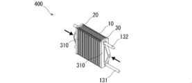
- FIG. 17 is a perspective view showing a state in which a load is applied simultaneously from above and below to a plurality of stacked modules 10 in the manufacturing apparatus 400.
- FIG. 18 is a perspective view showing a state in which a load is applied simultaneously from both ends in the horizontal direction to the plurality of stacked modules 10 in the manufacturing apparatus 400.
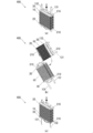
- FIG. 19 is a perspective view showing a state in which a load is applied to the stacked modules 10 from above before and after the top and bottom of the stacked modules 10 are reversed in the manufacturing apparatus 400.
- FIG. 20 shows a state in which a load is applied to the multi-layered module 10 from above before and after the top and bottom of the multi-layered module 10 is reversed while the load is applied in the manufacturing apparatus 400.
- FIG. 20 shows a state in which a load is applied to the multi-layered module 10 from above before and after the top and bottom of the multi-layered module 10 is reversed while the load is applied in the manufacturing apparatus 400.
- FIGS. 17 to 20 illustration of the rotation mechanism and the like is omitted, and only the minimum configuration is illustrated.
- the arrow in the figure indicates that a load is applied in the direction of the arrow.
- the manufacturing method and the manufacturing apparatus 400 according to the modified example of the second embodiment have a configuration in which a load is applied to the stacked modules 10 by a special method, and the manufacturing method and the manufacturing apparatus 300 according to the second embodiment described above. Different from the configuration.
- a pair of load applying jigs 310 are used to simultaneously apply the same or different loads to the modules 10 stacked in the vertical direction from above and below.
- the modules 10 stacked in the vertical direction are rotated in the horizontal direction, and then the horizontal ends of the modules 10 stacked in a plurality of layers are used with a pair of load applying jigs 310. Load simultaneously.
- a load is applied from above to the modules 10 stacked in a vertical direction using a pair of load applying jigs 310. Thereafter, as shown in FIG. 19B, the top and bottom of the stacked modules 10 are reversed. Further, as shown in FIG. 19 (c), a pair of load applying jigs 310 are used to apply a load from above to the modules 10 that are stacked in a reversed state.
- a load is applied from above to the modules 10 stacked in a vertical direction by using a pair of load applying jigs 310.
- FIG. 20B the top and bottom of the stacked modules 10 are reversed using a pair of load applying jigs 310 while the load is applied.
- FIG. 20 (c) a pair of load applying jigs 310 are used to apply a load from above to the modules 10 that are stacked in a reversed state.
- the load applying step simultaneously applies the same or different loads to the plurality of stacked modules 10 from above and below in the vertical direction.
- the load applying unit simultaneously applies the same or different loads to the plurality of stacked modules 10 from above and below in the vertical direction.
- a relatively large load is applied to the module 10 positioned below the module 10 due to the weight of the module 10. It is possible to prevent the load applied to the module 10 from becoming uneven.
- the spacing between adjacent modules 10 can be made uniform in the stacked modules 10.
- a load is applied from above in the vertical direction to the plurality of stacked modules 10, and then the top and bottom of the plurality of stacked modules 10 are reversed and then perpendicular to the plurality of stacked modules 10. It is good also as a structure which adds a load again from the direction upper direction.
- the interval between the modules 10 is relatively narrow due to the weight of the module 10.
- the lower module 10 that has been formed is disposed upward. That is, in the module 10 in which a plurality of modules are stacked, the module 10 positioned below the module 10 is subjected to a relatively large load due to the weight of the module 10 and the interval between the modules 10 is reduced. can do.
- the load applying step may be configured to continue applying a load to the plurality of stacked modules 10 when the top and bottom of the plurality of stacked modules 10 are reversed.
- the load applying step may be configured such that after a plurality of stacked modules 10 are arranged in the horizontal direction, a load is applied to the plurality of stacked modules 10 from both ends in the horizontal direction.
- FIG. 21 is a flowchart showing a method for inspecting the quality of the stacked modules 10 in the method for manufacturing the modules 10 using the manufacturing apparatus 500.
- FIG. 22 is a perspective view illustrating a state in which the stacked state of a plurality of stacked modules 10 is measured in the manufacturing apparatus 500.
- FIG. 23 is a perspective view showing a state in which the resistance value between a plurality of stacked modules 10 is measured in the manufacturing apparatus 500.
- FIG. 24 is a perspective view illustrating a state in which the internal volume of a plurality of stacked modules 10 is measured in the manufacturing apparatus 500.
- FIG. 25 is a perspective view showing the fuel cell 1 that has been inspected and removed from the manufacturing apparatus 500 in the manufacturing apparatus 500.
- the member indicated by the broken line is in a state before the operation, and the member indicated by the solid line is in operation or is in operation. The later state is shown.
- the configuration for inspecting the quality of the stacked modules 10 is different from the configurations of the manufacturing method and the manufacturing apparatus according to the first and second embodiments described above.
- the inspection process in the manufacturing method corresponds to the inspection unit of the manufacturing apparatus 500.
- a leak measuring device 510 corresponding to an inspection device is connected to the second end member 30 (S301 in FIG. 21).
- one medium is injected into the manifold provided in the plurality of stacked modules 10, and one medium leaking outside is measured from the gap between the adjacent modules 10 (FIG. 21).
- S302 it is determined whether or not the amount of leak is within a predetermined value. If it exceeds the predetermined value, the leak test is rejected and the process proceeds to S304. If it is within the specified value, the leak test is passed and the process goes to S305. Proceed (S303 in FIG. 21).
- the wiring 521 provided in the resistance measuring device 520 corresponding to the tester is connected to the electrode tabs 10i protruding from the modules 10 at both ends stacked in plural (S306 in FIG. 21). ).
- the resistance value of the cell between the modules 10 at the two stacked ends is measured using the resistance measuring device 520 (S307 in FIG. 21).
- an internal volume measuring device 530 corresponding to an inspection device is connected to the second end member 30 (S311 in FIG. 21).
- another medium is injected into the first manifold provided in the plurality of stacked modules 10 and discharged from the second manifold provided in the plurality of stacked modules 10.
- the discharge amount and pressure of the medium are measured (S312 in FIG. 21).
- the fuel cell 1 is removed from the manufacturing apparatus 500.
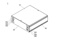
- the fuel cell 1 is configured, for example, by covering a first end member 20, a plurality of modules 10, and a second end member 30 that are stacked in this order with an exterior member.
- configurations such as an insulating plate and a current collecting plate are omitted.
- the manufacturing method according to the third embodiment includes an inspection process for inspecting the quality of a plurality of stacked modules 10.
- the manufacturing apparatus 500 according to the third embodiment includes an inspection device that is connected to a plurality of stacked modules 10 and inspects the quality of the modules 10.
- the manufacturing efficiency can be improved.
- the inspection process may be configured to measure a resistance value between a plurality of stacked modules 10 related to the fuel cell 1 using the resistance measuring device 520.
- the quality related to the resistance value of the module 10 can be inspected by measuring the resistance value between the stacked modules 10 continuously after the modules 10 are stacked. Manufacturing efficiency can be improved.
- one medium is injected into the manifold provided in the plurality of stacked modules 10 according to the fuel cell 1 using the leak measuring device 510, and one leaks to the outside through the gap between the adjacent modules 10.
- the medium may be measured.
- the inspection step uses the internal volume measuring device 530 to prepare the module 10 while injecting another medium under pressure to the first manifold provided in the plurality of stacked modules 10 according to the fuel cell 1.
- the internal volume of a plurality of stacked modules 10 may be measured based on the discharge amount and pressure of another medium discharged from the second manifold.
- FIG. 26 is a perspective view showing a state in which the process shown in FIG. 23 is performed at the end of the process shown in FIG.
- FIG. 27 is a perspective view showing a state in which the process shown in FIGS. 22 and 23 is performed at the end of the process shown in FIG.
- the manufacturing method and the manufacturing apparatus 600 according to the modified example of the third embodiment have a configuration in which the stacked module 10 is inspected in a state where a load is applied to the manufacturing method and the manufacturing apparatus 500 according to the above-described third embodiment. Different from the configuration.
- the manufacturing apparatus 600 shown in FIG. 26 performs the process shown in FIG. 23 at the end of the process shown in FIG. Specifically, the manufacturing apparatus 600 applies a resistance measuring instrument before attaching an exterior material to a plurality of stacked modules 10 or the like in a state in which a plurality of stacked modules 10 are applied using a load applying jig 310. 520 is used to measure the resistance value between the modules 10 at both ends stacked in a plurality.
- the manufacturing apparatus 600 uses a load measuring device 310 to apply a leak measurement device before attaching an exterior material to a plurality of stacked modules 10 or the like in a state where the plurality of stacked modules 10 are applied.
- the stacking state of the modules 10 stacked by using 510 is measured.
- the manufacturing apparatus 600 measures the resistance value between the modules 10 at both ends stacked by using the resistance measuring device 520.
- the inspection process inspects the quality of the module 10 in a state where a load is applied by the load addition process.
- the inspection unit inspects the quality of the module 10 in a state where a load is applied by the load addition unit.
- the quality of the module 10 is inspected before the exterior member is attached to the first end member 20, the plurality of stacked modules 10, and the second end member 30. Can do. Therefore, when there is a problem in the quality of the module 10, it is not necessary to remove the exterior member, and the module 10 can be easily repaired.
- the main column 131 corresponding to the first positioning member is inserted into the cooling fluid supply port 10d of the module 10, and the slave column 132 corresponding to the second positioning member is cooled to the module 10.
- the present invention is not limited to such a configuration.
- the main column 131 may be inserted into the cathode gas supply port 10c and the secondary column 132 may be inserted into the cathode gas discharge port 10h.
- the module 10 is provided with a long through hole, and the main pillar 131 is inserted along one end in the longitudinal direction of the through hole. It is good also as a structure inserted along the end follower pillar 132.
- FIG. The module 10 is provided with a reference surface for positioning at both ends in the longitudinal direction in a plane along the stacking direction of the long through holes.
- the main pillar 131 and the secondary pillar 132 each having a cylindrical shape with respect to the reference plane, with the three faces of the inner surfaces of the two manifold holes provided in the module 10 as the reference plane. It is not limited to the configuration along the line.
- two continuous surfaces of the inner surfaces of two manifold holes provided in the module 10 are used as a reference surface, and the outer periphery of a polygonal main column or subordinate column is set along the reference surface. It is good also as a structure.
- the two continuous surfaces serving as the reference surfaces are not limited to planar shapes, and may be, for example, a shape curved convexly toward the center of the manifold hole.
- the main pillar 131 may have a tip portion having a tapered shape at the tip, similarly to the follower pillar 132. In this case, the main pillar 131 can be easily inserted into the first opening 10 a of the module 10.
- the module 10 having a dedicated through hole for inserting the main pillar 131 and a dedicated through hole for inserting the follower pillar 132 may be used.
- the module 10 includes a reference surface for positioning in a plane along the stacking direction of the through holes.
- the laminated member to be laminated is not limited to the module 10 configured by alternately laminating a plurality of membrane electrode assemblies and separators used in the fuel cell 1.
- the laminated member is also applied to members other than the fuel cell 1.
- Fuel cell 10, 11, 12 modules (equivalent to laminated members), 10a, 11a first opening, 10aa, 11aa first reference plane, 10b, 11b second opening, 10bb, 11bb second reference plane, 10c, 20c, 30c cathode gas supply port, 10d, 20d, 30d Cooling fluid supply port, 10e, 20e, 30e anode gas supply port, 10f, 20f, 30f Anode gas outlet, 10g, 20g, 30g Cooling fluid outlet, 10h, 20h, 30h Cathode gas outlet, 10i electrode tab, 12a 1st notch part, 12aa first reference plane, 12b Second notch, 12bb second reference plane, 20 first end member, 30 second end member, 41 1st main plate, 42 second main plate, 43 first side plate, 44 second side plate, 100, 200, 300, 400, 500, 600 production equipment, 101 Guide, 102 positioning part, 110, 112 support base, 111 side plates, 120 reference table, 131 main pillar (corresponding to the following
Landscapes
- Life Sciences & Earth Sciences (AREA)
- Engineering & Computer Science (AREA)
- Manufacturing & Machinery (AREA)
- Sustainable Development (AREA)
- Sustainable Energy (AREA)
- Chemical & Material Sciences (AREA)
- Chemical Kinetics & Catalysis (AREA)
- Electrochemistry (AREA)
- General Chemical & Material Sciences (AREA)
- Fuel Cell (AREA)
- Laminated Bodies (AREA)
Abstract
【課題】積層部材を変形させることなく高い位置決め精度で積層することができる製造方法を提供する。 【解決手段】本製造方法は、それぞれ板状に形成した複数の積層部材を積層方向と直交する面上において互いに位置決めしつつ積層して製造する製造方法である。本製造方法は、案内工程と位置決め工程を有する。案内工程では、積層部材(モジュール10)の積層方向に沿う第1基準面10aaを、積層部材の積層方向に向かって配設した第1位置決め部材(主柱131)に沿わせた状態で、積層部材を積層方向に案内しつつ移動させる。位置決め工程では、積層部材が第1位置決め部材に沿って移動している途中で、積層部材の積層方向に沿う第2基準面10bbを、第1位置決め部材に並行して配設した第2位置決め部材(従柱132)に当接させて位置決めする。
Description
本発明は、製造方法およびその製造方法を具現化した製造装置に関する。
従来から、たとえば燃料電池は、セパレータと膜電極接合体とを交互に積層して構成している。燃料電池は、セパレータと膜電極接合体との積層数に応じて高出力を得られることから、その積層数を増加させることが望ましい。一方、積層するセパレータの位置が相対的にずれると、たとえば、セパレータの内部に備えたアノードガス用、カソードガス用、および冷却水用の貫通孔が、隣接したセパレータ同士で一致せず、本来の電池性能を達成できない。
このため、燃料電池を製造する際に、垂直に配設した2本の位置決め部材を基準にして、その2本の位置決め部材に対してセパレータの両端に備えた2個の位置決め孔を挿通させ、セパレータを高い位置精度で積層する構成がある(たとえば、特許文献1参照。)。
ところで、上記特許文献1の構成では、垂直に配置された2本の位置決め部材の高さが同一であることから、積層部材を水平に保った上で、その積層部材に備えた2つの位置決め孔を2本の位置決め部材に対して同時に挿通させる必要がある。
しかしながら、積層部材を2本の位置決め部材に対して嵌め合いするときに、その積層部材が接触して傾いてしまった場合や当初から傾いていた場合、積層部材に備えた2つの位置決め孔は、2本の位置決め部材に対してスムーズに挿通されない。その結果、積層部材の位置決め孔と、位置決め部材の先端とが局所的に干渉してしまい、負荷が掛かった積層部材が変形する虞があった。
本発明は、上記の課題を解決するためになされたものであり、積層部材を変形させることなく高い位置決め精度で積層することができる製造方法およびその製造方法を具現化した製造装置の提供を目的とする。
上記目的を達成する本発明に係る製造方法は、それぞれ板状に形成した複数の積層部材を積層方向と直交する面上において互いに位置決めしつつ積層して製造する製造方法である。本製造方法は、案内工程と位置決め工程を有する。案内工程では、積層部材の積層方向に沿う第1基準面を、積層部材の積層方向に向かって配設した第1位置決め部材に沿わせた状態で、積層部材を積層方向に案内しつつ移動させる。位置決め工程では、積層部材が第1位置決め部材に沿って移動している途中で、積層部材の積層方向に沿う第2基準面を、第1位置決め部材に並行して配設した第2位置決め部材に当接させて位置決めする。
上記目的を達成する本発明に係る製造装置は、それぞれ板状に形成した複数の積層部材を積層方向と直交する面上において互いに位置決めしつつ積層して製造する製造装置である。本製造装置は、第1位置決め部材、第2位置決め部材、移動部材、および制御部を有している。第1位置決め部材は、長尺形状からなり基準台に配設している。第2位置決め部材は、第1位置決め部材の長手方向に並行して基準台に配設し、第1位置決め部材よりも短い長尺形状からなる。移動部材は、積層部材を移動させる。制御部は、移動部材の作動を制御し、積層部材の積層方向に沿う第1基準面を第1位置決め部材に沿わせて移動させている途中で、積層部材の積層方向に沿う第2基準面を第2位置決め部材に沿わせて移動させつつ位置決めする。
以下、添付した図面を参照しながら、各実施形態について説明する。図面の説明において同一の要素には同一の符号を付し、重複する説明を省略する。図面における部材の大きさや比率は、説明の都合上誇張され実際の大きさや比率とは異なる場合がある。
(第1実施形態)
第1実施形態に係る製造方法およびその製造方法を具現化した製造装置100について、図1~図11を参照しながら説明する。
第1実施形態に係る製造方法およびその製造方法を具現化した製造装置100について、図1~図11を参照しながら説明する。
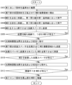
図1は、製造装置100を用いたモジュール10の製造方法を示すフローチャートである。図2は、製造装置100において、第1エンド部材20を基準台120に載置する状態を示す斜視図である。図3は、製造装置100において、モジュール10を仮置スペーサ141に仮置きする状態を示す斜視図である。図4は、製造装置100において、モジュール10を主柱131に挿通した後に従柱132に挿通する状態を、図3中の4-4線に沿って示す部分断面図である。図5は、製造装置100において、全ての仮置スペーサ141にモジュール10を仮置きした後、柱間隔調整治具150を主柱131および従柱132に挿通する状態を示す斜視図である。図6は、製造装置100において、仮置スペーサ141に仮置きしている全てのモジュール10を下方に順次移動させて積層する状態を示す斜視図である。図7は、製造装置100において、図6に示す工程を繰り返し、仮置スペーサ141に仮置きしていた全てのモジュール10を積層し終えた状態を示す斜視図である。
図8は、製造装置100において、図3~図7に示す工程を繰り返し、必要なモジュール10を全て積層し終えた状態を示す斜視図である。図9は、製造装置100において、柱間隔調整治具150を引き抜いた後、第2エンド部材30を最上部のモジュール10に積層する状態を示す斜視図である。図10は、製造装置100において、図2~図9に示す工程で用いる従柱132の先端部に係る様々な形態を示す斜視図である。図11は、製造装置100に備えた主柱131および従柱132に対してモジュール10を位置決めさせる様々な形態を示す斜視図である。
なお、図2~図9の斜視図において、同一の部材を破線と実線で図示している場合、原則として、破線で図示した部材は動作前の状態、実線で図示した部材は動作中または動作後の状態を示している。
まず、製造装置100を用いて積層するモジュール10について、図3を参照しながら説明する。
モジュール10は、積層部材に相当する。具体的には、モジュール10は、たとえば、燃料電池1に用いるセパレータと膜電極接合体(MEA)とを交互に複数積層して構成している。モジュール10は、長尺の板状に形成している。モジュール10は、その長手方向の一端に、カソードガス供給口10c、冷却流体供給口10d、およびアノードガス供給口10eに相当する貫通孔を備えている。同様に、モジュール10は、長手方向の他端に、アノードガス排出口10f、冷却流体排出口10g、およびカソードガス排出口10hに相当する貫通孔を備えている。モジュール10は、たとえば、冷却流体供給口10dに主柱131を挿通させ、冷却流体排出口10gに従柱132を挿通させる。主柱131は、第1位置決め部材に相当する。従柱132は、第2位置決め部材に相当する。
つぎに、製造装置100の構成および製造装置100を用いたモジュール10の積層方法について、図1~図11を参照しながら説明する。
具体的には、最初に、図2に示すように、製造装置100において、第1エンド部材20を主柱131および従柱132にそれぞれ挿通して、その第1エンド部材20を基準台120に載置する(図1のS101)。
製造装置100の基準台120は、たとえば、金属からなり、長方体に形成している。基準台120の上部は、第1エンド部材20を介してモジュール10を積層することから、平滑に形成している。基準台120は、上部の長手方向の両端に、丸穴を備えている。基準台120に備えた丸穴に、主柱131および従柱132を着脱可能に挿入している。主柱131は、長尺形状からなり基準台120に配設している。主柱131は、円柱形状からなり、その外周面を平滑に形成している。従柱132は、主柱131の長手方向に並行して基準台120に配設し、主柱131よりも短い長尺形状からなる。従柱132は、先細り形状からなる先端部132aと、その先端部132aを延在させる基材部132bからなる。従柱132の基材部132bは、その外周面を平滑に形成している。基準台120は、支持台110の上部に固定している。支持台110は、たとえば、金属からなり、板状に形成している。
燃料電池1の第1エンド部材20は、複数積層したモジュール10を、後述する第2エンド部材30と挟持する。第1エンド部材20は、たとえば、金属からなり、モジュール10と当接する部分に絶縁体を設けている。第1エンド部材20の外形形状は、モジュール10の外形形状と同様である。第1エンド部材20は、長方形からなる板状で形成し、その長手方向の一端に、カソードガス供給口20c、冷却流体供給口20d、およびアノードガス供給口20eに相当する貫通孔を備えている。同様に、第1エンド部材20は、長手方向の他端に、アノードガス排出口20f、冷却流体排出口20g、およびカソードガス排出口20hに相当する貫通孔を備えている。第1エンド部材20は、たとえば、冷却流体供給口20dに主柱131を挿通させ、冷却流体排出口20gに従柱132を挿通させる。
第1エンド部材20の搬送には、移動部材に相当する一対のハンドリング用ハンド171および172を用いる。一対のハンドリング用ハンド171および172は、それぞれ第1エンド部材20を挟持する。ハンドリング用ハンド171は第1エンド部材20の長手方向の一端をつかみ、ハンドリング用ハンド172は第1エンド部材20の長手方向の他端をつかむ。一対のハンドリング用ハンド171および172は、図示せぬ3軸の移動ステージによって、水平方向および垂直方向の任意の場所に移動自在としている。
つぎに、図3に示すように、モジュール10の積層方向下流側に位置する最下部の仮置スペーサ141を、その回転部141aを中心として180度時計方向に正転させて、モジュール10の積層領域に突出させる。仮置スペーサ141は、仮置部材に相当する。なお、図1中では、モジュール10をMODと表記している(図1のS102)。
製造装置100の仮置スペーサ141は、支柱142に対して一定の間隔で複数設けている。仮置スペーサ141は、モジュール10の中央部分を載置するように板状に形成している。仮置スペーサ141の長手方向の寸法は、モジュール10の長手方向の寸法よりも短い。一方、仮置スペーサ141の短手方向の寸法は、モジュール10の短手方向の寸法よりも若干長い。仮置スペーサ141は、その一端に備えた回転部141aを中心として、支柱142に対して回動自在に設けている。支柱142に複数設けた仮置スペーサ141は、個々に独立して回動させる。支柱142は、基準台120に隣り合うように、支持台110に対して垂直に配設している。
さらに、図3に示すように、モジュール10を降下させて、モジュール10の第1開口部10aを主柱131に挿通する。第1開口部10aは、たとえば、冷却流体供給口10dに相当する。モジュール10の第1開口部10aの第1基準面10aaに対して、主柱131を当接させた状態で、モジュール10を主柱131に沿って降下させる。第1基準面10aaは、第1開口部10aの内面であって、モジュール10の積層方向に沿った面内に備えている(図1のS103)。
さらに、図3に示すように、モジュール10をさらに降下させて、モジュール10の第2開口部10bを従柱132に挿通する。第2開口部10bは、たとえば、冷却流体排出口10gに相当する。モジュール10の第2開口部10bの第2基準面10bbに対して、従柱132を当接させた状態で、モジュール10を従柱132に沿って降下させる。第2基準面10bbは、第2開口部10bの内面であって、モジュール10の積層方向に沿った面内に備えている(図1のS104)。モジュール10をさらに降下させ、仮置スペーサ141に仮置きする(図1のS105)。
モジュール10の搬送には、移動部材に相当する一対のハンドリング用ハンド173および174を用いる。一対のハンドリング用ハンド173および174は、それぞれモジュール10を挟持する。ハンドリング用ハンド171はモジュール10の長手方向の一端をつかみ、ハンドリング用ハンド172はモジュール10の長手方向の他端をつかむ。一対のハンドリング用ハンド173および174は、図示せぬ3軸の移動ステージによって、水平方向および垂直方向の任意の場所に移動自在としている。
コントローラ180は、制御部に相当し、ハンドリング用ハンド173および174の作動を制御し、モジュール10の積層方向に沿う第1基準面10aaを主柱131に沿わせて移動させている途中で、モジュール10の積層方向に沿う第2基準面10bbを従柱132に沿わせて移動させつつ位置決めする。コントローラ180は、ROM、CPU、およびRAMを含んでいる。ROM(Read Only Memory)は、一対のハンドリング用ハンド173および174等の制御プログラムを格納している。CPU(Central Processing Unit)は、制御プログラムに基づいて一対のハンドリング用ハンド173および174等の動作を制御する。RAM(Random Access Memory)は、制御中の各種データを一時的に記憶する。
ここで、モジュール10を主柱131に挿通した後に従柱132に挿通する方法について、図4を参照しながらより具体的に説明する。
図4(a)中にAで示している領域が、案内部101に相当する。案内部101において、モジュール10を、主柱131から従柱132の方向に向かって下方に傾斜している状態で、主柱131に対して接近するように降下させる。モジュール10は、その第1開口部10aを主柱131に当接させた時点では、図中において反時計方向に傾斜している。ところが、モジュール10は、第1開口部10aの第1基準面10aaが主柱131に当接した状態で、その主柱131に沿って移動することから、傾斜した状態から水平の状態に調整される。モジュール10の厚みが厚い程、第1開口部10aの第1基準面10aaと主柱131が接触する面積が増加し、モジュール10の傾きを調整し易い。
図4(a)中にBで示している領域が、位置決め部102に相当する。位置決め部102において、モジュール10の第2開口部10bを従柱132に挿入させる。従柱132は、先細り形状からなる先端部132aと、その先端部132aを延在させ円柱形状からなる基材部132bを備えている。ここで、主柱131に当接しているモジュール10が、積層方向と交差する方向に角度誤差を生じていた場合でも、従柱132の先端部132aに当接しながら移動する過程で先細り形状の先端部132aに誘導されることから、角度誤差を解消することができる。
同様に、図4(b)に示すモジュール10を、案内部101において、従柱132から主柱131の方向に向かって下方に傾斜している状態で、主柱131に対して接近するように降下させる。モジュール10は、その第1開口部10aを主柱131に当接した時点では、図中の時計方向に傾斜している。ところが、モジュール10は、前述した図4(a)に示すモジュール10と同様に、第1開口部10aの第1基準面10aaが主柱131に当接した状態で、その主柱131に沿って移動することから、傾斜した状態から水平の状態に調整される。
さらに、位置決め部102において、モジュール10の第2開口部10bを従柱132に挿入させる。ここで、主柱131に当接しているモジュール10が、積層方向と交差する方向に角度誤差を生じていた場合でも、従柱132の先端部132aに当接しながら移動する過程で先細り形状の先端部132aに誘導されることから、角度誤差を解消することができる。
つぎに、図5に示すように、図3に示す工程から引き続き、仮置き可能な全ての仮置スペーサ141に対して、モジュール10の積層方向下流側の最下部に位置する仮置スペーサ141から順にモジュール10を仮置きする。すなわち、仮置き可能な全てのスペーサにモジュール10を仮置きするまで、図1のS102~S105の工程を繰り返す(図1のS106)。つぎに、主柱131と従柱132の相対位置を位置決めする柱間隔調整治具150を主柱131および従柱132に対してそれぞれ挿通する。柱間隔調整治具150は、基準台120の長手方向の両端に近接して備えた一対の基準側柱161および162の上部に設置する(図1のS107)。
製造装置100の柱間隔調整治具150は、保持部材に相当する。柱間隔調整治具150は、たとえば、金属からなり、板状に形成している。柱間隔調整治具150の長手方向の両端には、貫通孔からなる第1基準孔150aと第2基準孔150bを備えている。ここで、主柱131および従柱132は、複数のモジュール10を挿通させるために、長尺に形成していることから、たとえば傾斜して位置がずれる可能性がある。そこで、柱間隔調整治具150の第1基準孔150aを主柱131に挿通し、柱間隔調整治具150の第2基準孔150bを従柱132に挿通することによって、主柱131と従柱132の間隔を調整する。一対の基準側柱161および162は、基準台120の長手方向の両端に近接するように、支持台110に配設している。一対の基準側柱161および162は、たとえば、金属からなり、内部を大きく開口した板状に形成している。柱間隔調整治具150を一対の基準側柱161および162に設置すると、柱間隔調整治具150の絶対位置が補正される。
柱間隔調整治具150の搬送には、移動部材に相当する一対のハンドリング用ハンド175および176を用いる。一対のハンドリング用ハンド175および176は、それぞれ柱間隔調整治具150を挟持する。ハンドリング用ハンド171は柱間隔調整治具150の長手方向の一端をつかみ、ハンドリング用ハンド172は柱間隔調整治具150の長手方向の他端をつかむ。一対のハンドリング用ハンド175および176は、図示せぬ3軸の移動ステージによって、水平方向および垂直方向の任意の場所に移動自在としている。
つぎに、図6に示すように、モジュール10の積層方向下流側の最下部に位置するモジュール10について、そのモジュール10を仮置きしている仮置スペーサ141を、回転部141aを中心として180度反時計方向に逆転させる。この結果、仮置スペーサ141は、モジュール10の積層領域から退避する(図1のS108)。つぎに、仮置スペーサ141が退避して移動可能となったモジュール10を、下方に移動させて積層する(図1のS109)。
つぎに、図7に示すように、仮置スペーサ141に仮置きしていた全てのモジュール10を下方に移動させて積層するまでの間、図6に示す工程(図1のS108およびS109)を繰り返し行う(図1のS110)。仮置スペーサ141に仮置きされていたモジュール10が全て無くなった段階で、柱間隔調整治具150を主柱131および従柱132から引き抜く(図1のS111)。
つぎに、図8に示すように、積層すべきモジュール10を全て積層し終えるまでの間、図3および図5~図7に示す工程(図1のS102~S111)を繰り返し行う(図1のS112)。
つぎに、図9に示すように、第2エンド部材30を主柱131および従柱132にそれぞれ挿通し、その第2エンド部材30を最上部のモジュール10に積層する(図1のS113)。
燃料電池1の第2エンド部材30は、複数積層したモジュール10を、第1エンド部材20と挟持する。第2エンド部材30は、たとえば、金属からなり、モジュール10と当接する部分に絶縁体を設けている。第2エンド部材30の外形形状は、モジュール10の外形形状と同様である。第2エンド部材30は、長尺の板状で形成し、その長手方向の一端に、カソードガス供給口30c、冷却流体供給口30d、およびアノードガス供給口30eに相当する貫通孔を備えている。同様に、第2エンド部材30は、長手方向の他端に、アノードガス排出口30f、冷却流体排出口30g、およびカソードガス排出口30hに相当する貫通孔を備えている。第2エンド部材30は、たとえば、冷却流体供給口30dに主柱131を挿通させ、冷却流体排出口30gに従柱132を挿通させる。
第2エンド部材30の搬送には、一対のハンドリング用ハンド171および172を用いる。一対のハンドリング用ハンド171および172は、それぞれ第2エンド部材30を挟持する。ハンドリング用ハンド171は第2エンド部材30の長手方向の一端をつかみ、ハンドリング用ハンド172は第2エンド部材30の長手方向の他端をつかむ。一対のハンドリング用ハンド171および172は、図示せぬ3軸の移動ステージによって、水平方向および垂直方向の任意の場所に移動自在としている。
図2~図9に示す工程で用いる従柱132は、図10に示すように、その先端部を様々な構成にすることができる。
具体的には、図10(a)に示すように、先端部132aを、円錐台形状に形成してもよい。図10(a)に示す先端部132aは、図2~9に図示した先端部132aに相当する。同様に、図10(b)に示すように、先端部132cを円錐形状に形成してもよい。従柱132は、円錐台形状に形成した先端部132cと、その先端部132cを延在させ円柱形状からなる基材部132dを備えている。同様に、図10(c)に示すように、先端部132eを多段形状に形成してもよい。従柱132は、多段形状に形成した先端部132eと、その先端部132eを延在させ円柱形状からなる基材部132fを備えている。同様に、図10(d)に示すように、円錐台形状からなる先端部132gを、円柱形状からなる基材部132hから分離可能に形成してもよい。図10(d)に示す先端部132gの下部から突出して備えたネジを、基材部132hの上面に開口して備えたネジ溝にネジ留めする。
図2~図9に示す工程で用いる主柱131および従柱132は、図11に示すように、様々な形状に形成されたモジュール10の位置決めを行うことができる。
図2~図9で示した工程では、図11(a)に示すように、モジュール11の長手方向の両端近傍に開口した第1開口部11aおよび第2開口部11bに対して、主柱131および従柱132をそれぞれ挿通させて移動させる。第1基準面11aaは、第1開口部11aの内面であって、モジュール11の積層方向に沿った面内に備えている。第2基準面11bbは、第2開口部11bの内面であって、モジュール11の積層方向に沿った面内に備えている。
一方、図2~図9で示した工程では、図11(b)に相当する形態のモジュール12を用いてもよい。図11(b)に示すように、モジュール12の長手方向の両端の外周部に切り欠いて形成した第1切欠部12aおよび第2切欠部12bに対して、主柱131および従柱132を沿わせて移動させる。第1基準面12aaは、第1切欠部12aの内面であって、モジュール12の積層方向に沿った面内に備えている。第2基準面12bbは、第2切欠部12bの内面であって、モジュール12の積層方向に沿った面内に備えている。
上述した第1実施形態に係る製造方法およびその製造方法を具現化した製造装置100によれば、以下の作用効果を奏する。
第1実施形態に係る製造方法は、それぞれ板状に形成した複数のモジュール10を積層方向と直交する面上において互いに位置決めしつつ積層して製造する製造方法である。本製造方法は、案内工程と位置決め工程を有する。案内工程では、モジュール10の積層方向に沿う第1基準面10aaを、モジュール10の積層方向に向かって配設した主柱131に沿わせた状態で、モジュール10を積層方向に案内しつつ移動させる。位置決め工程では、モジュール10が主柱131に沿って移動している途中で、モジュール10の積層方向に沿う第2基準面10bbを、主柱131に並行して配設した従柱132に当接させて位置決めする。
同様に、第1実施形態に係る製造装置100は、それぞれ板状に形成した複数のモジュール10を積層方向と直交する面上において互いに位置決めしつつ積層して製造する。製造装置100は、主柱131、従柱132、ハンドリング用ハンド173および174、およびコントローラ180を有している。主柱131は、長尺形状からなり基準台120に配設している。従柱132は、主柱131の長手方向に並行して基準台120に配設し、主柱131よりも短い長尺形状からなる。ハンドリング用ハンド173および174は、モジュール10を移動させる。コントローラ180は、ハンドリング用ハンド173および174の作動を制御し、モジュール10の積層方向に沿う第1基準面10aaを主柱131に沿わせて移動させている途中で、モジュール10の積層方向に沿う第2基準面10bbを従柱132に沿わせて移動させつつ位置決めする。
このように構成した製造方法および製造装置100によれば、モジュール10が主柱131に沿って移動している途中で、モジュール10の積層方向に沿う第2基準面10bbを、主柱131に並行して配設した従柱132に当接させて位置決めする。このような製造方法および製造装置100によれば、モジュール10を変形させることなく高精度で積層することができる。
さらに、このように構成した製造方法および製造装置100によれば、モジュール10の位置決めは、主柱131および従柱132を用いた簡便な構成によって行い、複雑な機構やセンサー等を不要とすることができる。
さらに、このように構成した製造方法および製造装置100によれば、モジュール10を変形させないことから、モジュール10の変形に起因する製造の中断が発生せず、製造効率を向上させることができる。
さらに、第1基準面10aaおよび第2基準面10bbは、モジュール10に形成した第1開口部10aおよび第2開口部10bの内面にそれぞれ備え、主柱131および従柱132は、第1開口部10aおよび第2開口部10bにそれぞれ挿通する構成としてもよい。
このような構成によれば、モジュール10に形成した開口部の内面に基準面を備える簡便な構成とすることによって、開口部を設けるためにモジュール10の形状を大きくする必要がない。特に、たとえば、モジュール10の冷却流体供給口を第1開口部10aとして、冷却流体供給口の内面に第1基準面10aaを備え、かつ、モジュール10の冷却流体排出口を第2開口部10bとして、冷却流体排出口の内面に第2基準面10bbを備える構成とすれば、開口部を特別に設ける必要がない。
さらに、主柱131は、当接した第1基準面10aaを基準にして、モジュール10を積層方向と交差する方向に回転自在とする構成としてもよい。
このような構成によれば、積層するモジュール10が積層方向と交差する方向に角度誤差を生じていた場合でも、第1基準面10aaを基準にしてモジュール10を回転させることによって、その角度誤差を解消することができる。
さらに、主柱131は円柱形状または多角柱形状に形成し、第1基準面10aaは連続した3つの面からなる構成としてもよい。ここで、主柱131は、連続した3つの面に対して外周面をそれぞれ当接させた状態で、モジュール10を回転自在とする。
このような構成によれば、連続した3つの面からなる第1基準面10aaに対して、円柱形状または多角柱形状に形成した主柱131の外周を当接させる簡便な構成によって、モジュール10を主柱131に対して角度誤差を解消して位置決めすることができる。
さらに、従柱132の先端は、主柱131の先端よりも、モジュール10の積層方向に向かってモジュール10の厚み以上に後退させた構成としてもよい。すなわち、製造装置100において、従柱132は、主柱131よりもモジュール10の厚み以上、短くなるように構成してもよい。
このような構成によれば、モジュール10の第1基準面10aaに対して主柱131を十分に当接させた後に、そのモジュール10の第2基準面10bbに対して従柱132を当接させることができる。したがって、モジュール10が変形することを確実に防止できる。
さらに、従柱132は、その先端に先細り形状からなる先端部を備えた構成としてもよい。
このような構成によれば、主柱131に当接しているモジュール10が、積層方向と交差する方向に角度誤差を生じていた場合でも、従柱132の先端部132aに当接しながら移動する過程で、先細り形状の先端部132aに誘導されて角度誤差を解消することができる。
さらに、従柱132の先端部132aは、モジュール10の積層方向に沿って外方に直線状に傾斜させた構成としてもよい。
このような構成によれば、従柱132に当接したモジュール10が角度誤差を生じていた場合でも、テーパー形状に傾斜した先端部132aに当接しながら移動する過程で、モジュール10が先端部132aに誘導されて角度誤差をスムーズに解消することができる。したがって、モジュール10と従柱132との干渉を抑制することができ、モジュール10に加わる応力を大幅に軽減することができる。
さらに、従柱132の先端部132eは、屈折部位または屈曲部位を複数備えて多段形状に形成した構成としてもよい。
このような構成によれば、従柱132に当接したモジュール10が角度誤差を生じていた場合でも、多段形状に形成した先端部132eに当接しながら移動する過程で、モジュール10が先端部132eに誘導されて角度誤差を段階的に解消することができる。したがって、モジュール10と従柱132との干渉を抑制することができ、モジュール10に加わる応力を大幅に軽減することができる。
さらに、従柱132の先端部132gは、分離可能な構成としてもよい。
このような構成によれば、従柱132の先端部132gがたとえば経年劣化した場合には、その先端部132gを基材部132hから取外し、先端部132gのみを交換すればよく、交換に係るコストを低減することができる。
さらに、従柱132は、先端部132aを延在させ円柱形状または多角柱形状からなる基材部132bを備え、その基材部132bの全長をモジュール10の厚み以上に長い構成としてもよい。
このような構成によれば、従柱132に挿通させたモジュール10を、その従柱132の基材部132bの部分で十分に位置決めを行うことができる。
さらに、従柱132および主柱131は、それぞれモジュール10の積層方向と反対方向に向かって積み重ね自在な構成としてもよい。
このような構成によれば、モジュール10の積層数を増加させる場合には、従柱132および主柱131をそれぞれ積み重ねることで、容易に対応することができる。具体的には、たとえば従柱132において、図10(d)に示す基材部132hに対して、下部にネジ山を備えた基材部132hをネジ留めすることによって、その従柱132を積み重ねる。主柱131は、従柱132と同様の構成にすればよい。
さらに、モジュール10を挿通した後であって積層する前における主柱131と従柱132の位置を、柱間隔調整治具150を用いて位置決めした状態で保持する保持工程を有する構成としてもよい。すなわち、製造装置100は、モジュール10を挿通した後であって積層する前の主柱131および従柱132に接続し、主柱131と従柱132とを保持して位置決めする柱間隔調整治具150をさらに有する構成としてもよい。
このような構成によれば、モジュール10を挿通した後であって積層する前に、主柱131と従柱132の位置を、柱間隔調整治具150を用いて位置決めすることから、モジュール10をより高い位置決め精度で積層することができる。
さらに、複数の仮置スペーサ141を用いて複数のモジュール10を積層方向に沿って互いに離間させた状態で仮置きする仮置き工程を有する構成としてもよい。ここで、最初に、仮置き工程によって、モジュール10の積層方向下流側に位置する仮置スペーサ141から順に、複数のモジュール10の仮置きを行う。つぎに、保持工程によって、主柱131および従柱132を位置決めした状態で保持する。最後に、仮置き工程によって、モジュール10の積層方向下流側に位置するモジュール10から順に、モジュール10の仮置きを解除し、モジュール10の移動を再開させる。
このような構成によれば、1個のモジュール10を積層する度に、主柱131と従柱132の位置を、柱間隔調整治具150を用いて位置決めする必要がなく、製造効率を向上させることができる。
(第1実施形態の変形例)
第1実施形態の変形例に係る製造方法およびその製造方法を具現化した製造装置200について、図12を参照しながら説明する。
第1実施形態の変形例に係る製造方法およびその製造方法を具現化した製造装置200について、図12を参照しながら説明する。
図12は、製造装置200において、水平に並列して配設した主柱131および従柱132に対してモジュール10を挿通して仮置きする状態を示す斜視図である。
第1実施形態の変形例に係る製造方法および製造装置200は、モジュール10を吊り下げて移動させる構成が、前述した第1実施形態に係る製造方法および製造装置100の構成と異なる。
第1実施形態の変形例においては、前述した第1実施形態と同様の構成からなるものについて、同一の符号を使用し、前述した説明を省略する。
図12に示す製造装置200は、基準台120を図2に示す状態から時計方向に90°回転させた状態で、その基準台120を側方から側板111で保持している。側板111の下部は、支持台112に接合している。基準台120に挿通した主柱131および従柱132も、図2に示す状態から時計方向に90°回転した状態で、水平に並列して配設している。主柱131および従柱132に対して、移動部材に相当するハンドリング用ハンド177および178を用いて搬送したモジュール10を挿通し、そのモジュール10を吊り下げて移動させる。ハンドリング用ハンド177および178は、隣り合うモジュール10を離間させた状態で仮置きする。必要なモジュール10を主柱131および従柱132に挿通した後、第2エンド部材30を主柱131および従柱132に挿通し、複数のモジュール10を密接させて積層する。
上述した第1実施形態の変形例に係る製造方法およびその製造方法を具現化した製造装置200によれば、第1実施形態に係る作用効果に加えて、さらに以下の作用効果を奏する。
第1実施形態の変形例に係る製造方法および製造装置200によれば、案内工程および案内部は、長尺形状からなり水平に配置した主柱131に対してモジュール10を吊り下げて移動させる。また、位置決め工程および位置決め部は、長尺形状からなり水平に配置した従柱132に対してモジュール10を吊り下げて移動させる。
このような構成によれば、複数のモジュール10を積層する際に、隣接するモジュール10から荷重を受けることを防止できる。さらに、主柱131および従柱132に吊り下げられたモジュール10は自重で静止することから、仮置スペーサ141を不要とすることができる。
さらに、たとえば、案内工程および位置決め工程は、隣り合うモジュール10を離間させた状態で移動させる構成としてもよい。
このような構成によれば、モジュール10を移動させる際に、そのモジュール10が振動してしまっても、隣り合うモジュール10との接触を防止することができる。したがって、隣り合うモジュール10の接触に起因したモジュール10の破損を防止できる。
(第2実施形態)
第2実施形態に係る製造方法およびその製造方法を具現化した製造装置300について、図13~図16を参照しながら説明する。
第2実施形態に係る製造方法およびその製造方法を具現化した製造装置300について、図13~図16を参照しながら説明する。
図13は、製造装置300を用いたモジュール10の製造方法において、積層したモジュール10に対して荷重を付加する方法を示すフローチャートである。図14は、製造装置300において、荷重付加部材310を第2エンド部材30に載置し、柱間隔調整治具150を取り付け、モジュール10を付勢する状態を示す斜視図である。図15は、製造装置300において、荷重付加部材310によってモジュール10を付勢しつつ、外装部材をモジュール10等に取り付ける状態を示す斜視図である。図16は、製造装置300において、押圧部材320、柱間隔調整治具150、および荷重付加部材310を取り外した後の状態を示す斜視図である。
なお、図14~図16の斜視図において、同一の部材を破線と実線で図示している場合、原則として、破線で図示した部材は動作前の状態、実線で図示した部材は動作中または動作後の状態を示している。
第2実施形態に係る製造方法および製造装置300は、積層したモジュール10に対して荷重を付加する構成が、前述した第1実施形態に係る製造方法および製造装置100の構成と異なる。第2実施形態において、製造方法における荷重付加工程は、製造装置300の荷重付加部に対応している。
第2実施形態においては、前述した第1実施形態等と同様の構成からなるものについて、同一の符号を使用し、前述した説明を省略する。
荷重付加部と対応した荷重付加工程では、図13のフローチャートに示すように、複数積層したモジュール10に対して荷重を付加する。
まず、図9に示す工程から引き続き、図14に示すように複数積層したモジュール10に対して荷重を付加する。具体的には、荷重付加部材310を主柱131および従柱132にそれぞれ挿通して第2エンド部材30に載置する。荷重付加部材310は、たとえば、金属からなり、板状に形成している。荷重付加部材310の長手方向の両端には、主柱131および従柱132を挿通する第1孔310aおよび第2孔310bを備えている(図13のS201)。つぎに、柱間隔調整治具150を主柱131および従柱132に対してそれぞれ挿通して一対の基準側柱161および162の上部に設置する(図13のS202)。つぎに、押圧部材320を、柱間隔調整治具150の中央に開口した挿通孔150cに挿通させて、荷重付加部材310を押圧する。押圧部材320は、たとえば、金属からなり、円柱形状に形成している(図13のS203)。つぎに、荷重付加治具310によって、第2エンド部材30を介し複数積層したモジュール10を付勢する(図13のS204)。
つぎに、図14に示す工程から引き続き、図15に示すように、荷重付加部材310によって複数積層されたモジュール10を押圧した状態で、複数積層したモジュール10等に対して外装部材を取り付ける。具体的には、第1主板41、第2主板42、第1側板43、および第2側板44からなる外装部材を、図示せぬネジを用いて、第1エンド部材20および第2エンド部材30に備えられたネジ溝にネジ留めする。第1主板41、第2主板42、第1側板43、および第2側板44は、それぞれ金属板からなる(図13のS205)。
つぎに、図15に示す工程から引き続き、図16に示すように、押圧部材320を柱間隔調整治具150の挿通孔150cから引き抜いて取り外す(図13のS206)。つぎに、柱間隔調整治具150を主柱131および従柱132から引き抜いて取り外す(図13のS207)。つぎに、荷重付加部材310を主柱131および従柱132から引き抜いて取り外す(図13のS208)。最後に、主柱131および従柱132を、第1エンド部材20、複数積層したモジュール10、第2エンド部材30から引き抜いて取り外す(図13のS209)。
上述した第2実施形態に係る製造方法およびその製造方法を具現化した製造装置300によれば、第1実施形態等に係る作用効果に加えて、さらに以下の作用効果を奏する。
第2実施形態に係る製造方法によれば、複数積層されたモジュール10に対して荷重を付加する荷重付加工程を有する。同様に、第2実施形態に係る製造装置300によれば、複数積層されたモジュール10に当接し、モジュール10の積層方向に対して荷重を付加する荷重付加部材310を有する。
このように構成した製造方法および製造装置300によれば、複数積層されたモジュール10において、隣接するモジュール10間に生じている隙間を無くすことができる。したがって、モジュール10を複数積層して構成した燃料電池1を使用するときに、隣接するモジュール10間から冷却水等が漏洩することを防止できる。さらに、積層したモジュール10を十分に密着させることによって、モジュール10のセル間の抵抗値を低下させることができる。
さらに、たとえば、荷重付加工程は、荷重を付加した複数のモジュール10からの反発力に応じて、荷重を増減させる構成としてもよい。
このような構成によれば、複数積層されたモジュール10において、たとえば、隣接するモジュール10間に生じている隙間が大きく、複数のモジュール10からの反発力が弱いときは、複数のモジュール10に付加する荷重を増加させることができる。したがって、隣接するモジュール10間に生じている隙間を確実に無くすことができる。
(第2実施形態の変形例)
第2実施形態の変形例に係る製造方法およびその製造方法を具現化した製造装置400について、図17~図20を参照しながら説明する。
第2実施形態の変形例に係る製造方法およびその製造方法を具現化した製造装置400について、図17~図20を参照しながら説明する。
図17は、製造装置400において、複数積層されたモジュール10に対して上方および下方から荷重を同時に付加する状態を示す斜視図である。図18は、製造装置400において、複数積層されたモジュール10に対して水平方向の両端から荷重を同時に付加する状態を示す斜視図である。図19は、製造装置400において、複数積層されたモジュール10の天地を逆転させる前と後で、複数積層されたモジュール10に対して上方から荷重を付加する状態を示す斜視図である。図20は、製造装置400において、複数積層されたモジュール10の天地を、荷重を付加したままの状態で逆転させる前と後で、複数積層されたモジュール10に対して上方から荷重を付加する状態を示す斜視図である。
図17~図20に示す製造装置400においては、回転機構等の図示を省略し、最低限の構成のみを図示している。図中の矢印は、その矢印の方向に向かって、荷重を付加していることを示している。
第2実施形態の変形例に係る製造方法および製造装置400は、積層したモジュール10に対して特殊な方法で荷重を付加する構成が、前述した第2実施形態に係る製造方法および製造装置300の構成と異なる。
第2実施形態の変形例においては、前述した第1および第2実施形態等と同様の構成からなるものについて、同一の符号を使用し、前述した説明を省略する。
図17に示す製造装置400では、一対の荷重付加治具310を用い、垂直方向に複数積層されたモジュール10に対して上方および下方から、同一または異なる荷重をそれぞれ同時に付加する。
図18に示す製造装置400では、垂直方向に複数積層されたモジュール10を水平方向に回転させてから、一対の荷重付加治具310を用い、複数積層されたモジュール10に対して水平方向の両端から荷重をそれぞれ同時に付加する。
図19に示す製造装置400では、図19(a)に示すように、一対の荷重付加治具310を用い、垂直方向に複数積層されたモジュール10に対して上方から荷重を付加する。その後、図19(b)に示すように、複数積層されたモジュール10の天地を逆転させる。さらに、図19(c)に示すように、一対の荷重付加治具310を用い、天地を逆転させた状態で複数積層されたモジュール10に対して上方から荷重を付加する。
図20に示す製造装置400では、図20(a)に示すように、一対の荷重付加治具310を用い、垂直方向に複数積層されたモジュール10に対して上方から荷重を付加する。その後、図20(b)に示すように、一対の荷重付加治具310を用い、荷重を付加したままの状態で、複数積層されたモジュール10の天地を逆転させる。さらに、図20(c)に示すように、一対の荷重付加治具310を用い、天地を逆転させた状態で複数積層されたモジュール10に対して上方から荷重を付加する。
上述した第2実施形態の変形例に係る製造方法およびその製造方法を具現化した製造装置400によれば、第1および第2実施形態等に係る作用効果に加えて、さらに以下の作用効果を奏する。
第2実施形態の変形例に係る製造方法によれば、荷重付加工程は、複数積層されたモジュール10に対して垂直方向上方および下方から、同一または異なる荷重をそれぞれ同時に付加する。同様に、第2実施形態の変形例に係る製造方法によれば、荷重付加部は、複数積層されたモジュール10に対して垂直方向上方および下方から、同一または異なる荷重をそれぞれ同時に付加する。
このように構成した製造方法および製造装置400によれば、複数積層されたモジュール10において、その下方に位置するモジュール10に対し、モジュール10の自重に起因して相対的に大きな荷重が掛かり、複数のモジュール10に掛かる荷重が不均一になることを防止できる。すなわち、複数積層されたモジュール10に対して垂直方向上方および下方から荷重を付加することによって、複数積層したモジュール10において、隣接したモジュール10間の間隔を均一にすることができる。特に、複数積層されたモジュール10に対して、垂直方向上方よりも下方から相対的に大きな荷重を付加することによって、モジュール10の自重に起因した荷重のばらつきをキャンセルすることができる。すなわち、複数積層したモジュール10のうち、上方に積層したモジュール10間の間隔が大きく、下方に積層したモジュール10間の間隔が狭くなることを防止することができる。
さらに、荷重付加工程は、複数積層されたモジュール10に対して垂直方向上方から荷重を付加した後、複数積層されたモジュール10の天地を逆転させてから、複数積層されたモジュール10に対して垂直方向上方から荷重を再度付加する構成としてもよい。
このような構成によれば、モジュール10間の間隔が相対的に広くなっていた上方のモジュール10を下方に配設しつつ、モジュール10の自重に起因しモジュール10間の間隔が相対的に狭くなっていた下方のモジュール10を上方に配設する。すなわち、複数積層されたモジュール10において、その下方に位置するモジュール10の方が、モジュール10の自重に起因して相対的に大きな荷重が掛かり、モジュール10間の間隔が狭くなっていた状態を解消することができる。
さらに、荷重付加工程は、複数積層されたモジュール10の天地を逆転させるときに、複数積層されたモジュール10に対する荷重の付加を継続させる構成としてもよい。
このような構成によれば、複数積層されたモジュール10の天地を逆転させるときに、モジュール10間の間隔が広がってしまうことを防止することができる。
さらに、荷重付加工程は、複数積層されたモジュール10を水平方向に配設した後、複数積層されたモジュール10に対して水平方向の両端から荷重を付加する構成としてもよい。
このような構成によれば、隣接したモジュール10間に自重が作用しない状態で、複数積層されたモジュール10に対して荷重を付加することができる。すなわち、複数積層したモジュール10において、自重の影響を受けることなく、隣接したモジュール10間の間隔を均一にすることができる。
(第3実施形態)
第3実施形態に係る製造方法およびその製造方法を具現化した製造装置500について、図21~図25を参照しながら説明する。
第3実施形態に係る製造方法およびその製造方法を具現化した製造装置500について、図21~図25を参照しながら説明する。
図21は、製造装置500を用いたモジュール10の製造方法において、積層したモジュール10の品質を検査する方法を示すフローチャートである。図22は、製造装置500において、複数積層したモジュール10の積層状態を測定する状態を示す斜視図である。図23は、製造装置500において、複数積層したモジュール10間の抵抗値を測定する状態を示す斜視図である。図24は、製造装置500において、複数積層したモジュール10の内容積を測定する状態を示す斜視図である。図25は、製造装置500において、検査を完了させ製造装置500から取り外した燃料電池1を示す斜視図である。
なお、図22~図25の斜視図において、同一の部材を破線と実線で図示している場合、原則として、破線で図示した部材は動作前の状態、実線で図示した部材は動作中または動作後の状態を示している。
第3実施形態に係る製造方法および製造装置500は、積層したモジュール10の品質を検査する構成が、前述した第1および第2実施形態に係る製造方法および製造装置の構成と異なる。第3実施形態において、製造方法における検査工程は、製造装置500の検査部に対応している。
第3実施形態においては、前述した第1および第2実施形態等と同様の構成からなるものについて、同一の符号を使用し、前述した説明を省略する。
検査部と対応した検査工程では、図21のフローチャートに示すように、積層したモジュール10の品質を検査する。
まず、図16に示す工程から引き続き、図22に示すように複数積層したモジュール10の積層状態を検査する。
具体的には、図22に示すように、検査器に相当するリーク測定器510を、第2エンド部材30に接続する(図21のS301)。つぎに、リーク測定器510を用い、複数積層したモジュール10に備えたマニホールドに対して一の媒体を注入し、隣接したモジュール10の隙間から外部にリークする一の媒体を測定する(図21のS302)。つぎに、リークの量が予め定めた規定値以内かを判定し、規定値を超えていればリーク検査は不合格でありS304に進み、規定値以内であればリーク検査は合格でありS305に進む(図21のS303)。ここで、S304に進んだ場合は、複数積層したモジュール10の積層状態を改修し、モジュール10間において隙間が生じないようにした後にS302に戻る(図21のS304)。一方、S305に進んだ場合は、リーク検査機器を、第2エンド部材30から取り外す(図21のS305)。
つぎに、図22に示す工程から引き続き、図23に示すようにモジュール10間のセルの抵抗値を検査する。
具体的には、図23に示すように、検査器に相当する抵抗測定器520に備えた配線521を、複数積層した両端のモジュール10からそれぞれ突出した電極タブ10iに接続する(図21のS306)。つぎに、抵抗測定器520を用いて、複数積層した両端のモジュール10間のセルの抵抗値を測定する(図21のS307)。つぎに、モジュール10間のセルの抵抗値が予め定めた規定値以内かを判定し、規定値を超えていれば抵抗値検査は不合格でありS309に進み、規定値以内であれば抵抗値検査は合格でありS310に進む(図21のS308)。ここで、S309に進んだ場合は、複数積層したモジュール10の密着具合を改修した後にS307に戻る。積層したモジュール10を十分に密着させることによって、セルの抵抗値を低下させることができる(図21のS309)。一方、S310に進んだ場合は、抵抗測定器520に備えた配線521を、複数積層した両端のモジュール10の電極タブ10iから取り外す(図21のS310)。
つぎに、図23に示す工程から引き続き、図24に示すように複数積層したモジュール10の内容積を検査する。
具体的には、図24に示すように、検査器に相当する内容積測定器530を第2エンド部材30に接続する(図21のS311)。つぎに、内容積測定器530を用い、複数積層したモジュール10に備えた第1のマニホールドに対して他の媒体を注入しつつ、複数積層したモジュール10に備えた第2のマニホールドから吐出した他の媒体の吐出量と圧力を測定する(図21のS312)。つぎに、内容積値が予め定めた規定値以内かを判定し、規定値を超えていれば内容積検査は不合格でありS314に進み、規定値以内であれば内容積検査は合格でありS315に進む(図21のS313)。ここで、S314に進んだ場合は、複数積層したモジュール10のマニホールド等を改修した後にS312に戻る(図21のS314)。一方、S315に進んだ場合は、内容積測定器530を第2エンド部材30から取り外す(図21のS315)。
最後に、図25に示すように、製造装置500から検査を完了した燃料電池1取り出す。燃料電池1は、たとえば、第1エンド部材20、複数のモジュール10、第2エンド部材30の順で積層したものを、外装部材で被覆して構成している。燃料電池1では、絶縁板や集電板等の構成は省略している。
上述した第3実施形態に係る製造方法およびその製造方法を具現化した製造装置500によれば、第1および第2実施形態等に係る作用効果に加えて、さらに以下の作用効果を奏する。
第3実施形態に係る製造方法によれば、複数積層されたモジュール10の品質を検査する検査工程を有する。同様に、第3実施形態に係る製造装置500によれば、複数積層されたモジュール10に接続し、モジュール10の品質を検査する検査器を有する。
このように構成した製造方法および製造装置500によれば、モジュール10を積層した後に連続して、そのモジュール10の品質を検査することができることから、製造効率を向上させることができる。
具体的には、検査工程は、抵抗測定器520を用いて、燃料電池1に係る複数積層したモジュール10間の抵抗値を測定する構成としてもよい。
このような構成によれば、モジュール10を積層した後に連続して、複数積層したモジュール10間の抵抗値を測定することによって、そのモジュール10の抵抗値に係る品質を検査することができることから、製造効率を向上させることができる。
さらに、検査工程は、リーク測定器510を用いて、燃料電池1に係る複数積層したモジュール10に備えたマニホールドに対して一の媒体を注入し、隣接したモジュール10の隙間から外部にリークする一の媒体を測定する構成としてもよい。
このような構成によれば、モジュール10を積層した後に連続して、複数積層したモジュール10の積層状態を測定することによって、そのモジュール10の隙間の有無に係る品質を検査することができることから、製造効率を向上させることができる。
さらに、検査工程は、内容積測定器530を用いて、燃料電池1に係る複数積層したモジュール10に備えた第1のマニホールドに対して他の媒体を加圧して注入しつつ、モジュール10に備えた第2のマニホールドから吐出させた他の媒体の吐出量と圧力に基づき、複数積層したモジュール10の内容積を測定する構成としてもよい。
このような構成によれば、モジュール10を積層した後に連続して、複数積層したモジュール10の内容積を測定することによって、そのモジュール10の内容積に係る品質を検査することができることから、製造効率を向上させることができる。
(第3実施形態の変形例)
第3実施形態の変形例に係る製造方法およびその製造方法を具現化した製造装置600について、図26および図27を参照しながら説明する。
第3実施形態の変形例に係る製造方法およびその製造方法を具現化した製造装置600について、図26および図27を参照しながら説明する。
図26は、製造装置600において、図14に示す工程の最後に、図23に示す工程を行う状態を示す斜視図である。図27は、製造装置600において、図14に示す工程の最後に、図22および図23に示す工程を行う状態を示す斜視図である。
第3実施形態の変形例に係る製造方法および製造装置600は、積層したモジュール10に対して荷重を付加した状態で検査する構成が、前述した第3実施形態に係る製造方法および製造装置500の構成と異なる。
第3実施形態の変形例においては、前述した第1および第2実施形態等と同様の構成からなるものについて、同一の符号を使用し、前述した説明を省略する。
図26に示す製造装置600は、図14に示す工程の最後に、図23に示す工程を行う。具体的には、製造装置600は、荷重付加治具310を用いて複数積層されたモジュール10に付加をかけた状態で、複数積層されたモジュール10等に外装材を取り付ける前に、抵抗測定器520を用いて複数積層した両端のモジュール10間の抵抗値を測定する。
図27に示す製造装置600は、図14に示す工程の最後に、図22および図23に示す工程を行う。具体的には、製造装置600は、荷重付加治具310を用いて複数積層されたモジュール10に付加をかけた状態で、複数積層されたモジュール10等に外装材を取り付ける前に、リーク測定器510を用いて複数積層したモジュール10の積層状態を測定する。さらに、製造装置600は、抵抗測定器520を用いて複数積層した両端のモジュール10間の抵抗値を測定する。
上述した第3実施形態の変形例に係る製造方法およびその製造方法を具現化した製造装置600によれば、第1~第3実施形態等に係る作用効果に加えて、さらに以下の作用効果を奏する。
第3実施形態の変形例に係る製造方法によれば、検査工程は、荷重付加工程によって荷重が付加された状態のモジュール10の品質を検査する。同様に、第3実施形態の変形例に係る製造装置600によれば、検査部は、荷重付加部によって荷重が付加された状態のモジュール10の品質を検査する。
このように構成した製造方法および製造装置600によれば、外装部材を第1エンド部材20、複数積層されたモジュール10、および第2エンド部材30に取り付ける前に、モジュール10の品質を検査することができる。したがって、モジュール10の品質に問題があった場合に、外装部材を取り外す手間が不要であり、モジュール10の改修を容易に行うことができる。
そのほか、本発明は、特許請求の範囲に記載された構成に基づき様々な改変が可能であり、それらについても本発明の範疇である。
たとえば、第1~第3実施形態等において、第1位置決め部材に相当する主柱131をモジュール10の冷却流体供給口10dに挿通し、第2位置決め部材に相当する従柱132をモジュール10の冷却流体排出口10gに挿通する構成で説明した。しかしながら、このような構成に限定されることはなく、たとえば、主柱131をカソードガス供給口10cに挿通し、従柱132をカソードガス排出口10hに挿通する構成としてもよい。
また、第1~第3実施形態等において、モジュール10に、長尺な貫通孔を備え、その貫通孔の長手方向の一端に主柱131を沿わせて挿通し、貫通孔の長手方向の他端に従柱132を沿わせて挿通する構成としてもよい。モジュール10は、長尺な貫通孔の積層方向に沿った面内であって、その長手方向の両端に位置決め用の基準面をそれぞれ備える。
また、第1~第3実施形態等において、モジュール10に備えられた2個のマニホールド孔の内面の3面を基準面として、その基準面に対して円柱形状からなる主柱131や従柱132を沿わせる構成に限定されることはない。たとえば、各実施形態において、モジュール10に備えられた2個のマニホールド孔の内面の連続する2面を基準面として、その基準面に対して多角形状からなる主柱や従柱の外周を沿わせる構成としてもよい。基準面とする連続する2面は、それぞれ平面形状に限定されることはなく、たとえば、マニホールド孔の中心に向かって凸状に湾曲した形状としてもよい。
また、第1~第3実施形態等において、主柱131は、従柱132と同様に、その先端に先細り形状からなる先端部を備える構成としてもよい。この場合、主柱131は、モジュール10の第1開口部10aに挿通し易くなる。
また、第1~第3実施形態等において、主柱131を挿通する専用の貫通孔と従柱132を挿通する専用の貫通孔をそれぞれ備えたモジュール10を用いる構成としてもよい。モジュール10は、各貫通孔の積層方向に沿った面内に位置決め用の基準面を備える。
また、第1~第3実施形態等において、積層する積層部材は、燃料電池1に用いる膜電極接合体とセパレータとを交互に複数積層して構成したモジュール10に限定されることはない。積層部材は、燃料電池1以外の部材にも適用される。
本出願は、2013年3月4日に出願された日本特許出願番号2013-042219号に基づいており、その開示内容は、参照され、全体として、組み入れられている。
1 燃料電池、
10,11,12 モジュール(積層部材に相当)、
10a,11a 第1開口部、
10aa,11aa 第1基準面、
10b,11b 第2開口部、
10bb,11bb 第2基準面、
10c,20c,30c カソードガス供給口、
10d,20d,30d 冷却流体供給口、
10e,20e,30e アノードガス供給口、
10f,20f,30f アノードガス排出口、
10g,20g,30g 冷却流体排出口、
10h,20h,30h カソードガス排出口、
10i 電極タブ、
12a 第1切欠部、
12aa 第1基準面、
12b 第2切欠部、
12bb 第2基準面、
20 第1エンド部材、
30 第2エンド部材、
41 第1主板、
42 第2主板、
43 第1側板、
44 第2側板、
100,200,300,400,500,600 製造装置、
101 案内部、
102 位置決め部、
110,112 支持台、
111 側板、
120 基準台、
131 主柱(第1位置決め部材に相当)、
132 従柱(第2位置決め部材に相当)、
132a,132c,132e,132g 先端部、
132b,132d,132f,132h 基材部、
141 仮置スペーサ(仮置部材に相当)、
141a 回転部、
142 支柱、
150 柱間隔調整治具(保持部材に相当)、
150a 第1基準孔、
150b 第2基準孔、
150c 挿通孔、
161,162 基準側柱、
171,172,173,174,175,176,177,178 ハンドリング用ハンド(移動部材に相当)、
180 コントローラ(制御部に相当)、
310 荷重付加部材、
310a 第1孔、
310b 第2孔、
320 押圧部材、
510 リーク測定器(検査器に相当)、
520 抵抗測定器(検査器に相当)、
521 配線、
530 内容積測定器(検査器に相当)。
10,11,12 モジュール(積層部材に相当)、
10a,11a 第1開口部、
10aa,11aa 第1基準面、
10b,11b 第2開口部、
10bb,11bb 第2基準面、
10c,20c,30c カソードガス供給口、
10d,20d,30d 冷却流体供給口、
10e,20e,30e アノードガス供給口、
10f,20f,30f アノードガス排出口、
10g,20g,30g 冷却流体排出口、
10h,20h,30h カソードガス排出口、
10i 電極タブ、
12a 第1切欠部、
12aa 第1基準面、
12b 第2切欠部、
12bb 第2基準面、
20 第1エンド部材、
30 第2エンド部材、
41 第1主板、
42 第2主板、
43 第1側板、
44 第2側板、
100,200,300,400,500,600 製造装置、
101 案内部、
102 位置決め部、
110,112 支持台、
111 側板、
120 基準台、
131 主柱(第1位置決め部材に相当)、
132 従柱(第2位置決め部材に相当)、
132a,132c,132e,132g 先端部、
132b,132d,132f,132h 基材部、
141 仮置スペーサ(仮置部材に相当)、
141a 回転部、
142 支柱、
150 柱間隔調整治具(保持部材に相当)、
150a 第1基準孔、
150b 第2基準孔、
150c 挿通孔、
161,162 基準側柱、
171,172,173,174,175,176,177,178 ハンドリング用ハンド(移動部材に相当)、
180 コントローラ(制御部に相当)、
310 荷重付加部材、
310a 第1孔、
310b 第2孔、
320 押圧部材、
510 リーク測定器(検査器に相当)、
520 抵抗測定器(検査器に相当)、
521 配線、
530 内容積測定器(検査器に相当)。
Claims (30)
- それぞれ板状に形成した複数の積層部材を積層方向と直交する面上において互いに位置決めしつつ積層して製造する製造方法であって、
前記積層部材の積層方向に沿う第1基準面を、前記積層部材の積層方向に向かって配設した第1位置決め部材に沿わせた状態で、前記積層部材を積層方向に案内しつつ移動させる案内工程と、
前記積層部材が前記第1位置決め部材に沿って移動している途中で、前記積層部材の積層方向に沿う第2基準面を、前記第1位置決め部材に並行して配設した第2位置決め部材に当接させて位置決めする位置決め工程と、を有する製造方法。 - 前記第1基準面および前記第2基準面は、前記積層部材に形成した第1開口部および第2開口部の内面にそれぞれ備え、
前記第1位置決め部材および第2位置決め部材は、前記第1開口部および前記第2開口部にそれぞれ挿通する請求項1に記載の製造方法。 - 前記第1位置決め部材は、当接した前記第1基準面を基準にして、前記積層部材を積層方向と交差する方向に回転自在とする請求項1または2に記載の製造方法。
- 前記第1位置決め部材は、円柱形状または多角柱形状に形成し、
前記第1基準面は、連続した3つの面からなり、
前記第1位置決め部材は、連続した3つの前記面に対して外周面をそれぞれ当接させた状態で、前記積層部材を回転自在とする請求項3に記載の製造方法。 - 前記積層部材を挿通した後であって積層する前における前記第1位置決め部材と前記第2位置決め部材との位置を保持部材を用いて位置決めした状態で保持する保持工程と、をさらに有する請求項1~4のいずれか1項に記載の製造方法。
- 複数の仮置部材を用いて複数の前記積層部材を積層方向に沿って互いに離間させた状態で仮置きする仮置き工程を、さらに有し、
前記仮置き工程によって、前記積層部材の積層方向下流側に位置する前記仮置部材から順に、複数の前記積層部材の仮置きを行った後、
前記保持工程によって、前記第1位置決め部材および前記第2位置決め部材を保持してから、
前記仮置き工程によって、前記積層部材の積層方向下流側に位置する前記積層部材から順に、前記積層部材の仮置きを解除し、前記積層部材の移動を再開させる請求項5に記載の製造方法。 - 前記案内工程は、長尺形状からなり水平に配置した前記第1位置決め部材に対して前記積層部材を吊り下げて移動させ、
前記位置決め工程は、長尺形状からなり水平に配置した前記第2位置決め部材に対して前記積層部材を吊り下げて移動させる請求項1~6のいずれか1項に記載の製造方法。 - 前記案内工程および前記位置決め工程は、隣り合う前記積層部材を離間させた状態で移動させる請求項7に記載の製造方法。
- 複数積層された前記積層部材に対して荷重を付加する荷重付加工程を、さらに有する請求項1~8のいずれか1項に記載の製造方法。
- 前記荷重付加工程は、複数積層された前記積層部材に対して垂直方向上方および下方から、同一または異なる荷重をそれぞれ同時に付加する請求項9に記載の製造方法。
- 前記荷重付加工程は、複数積層された前記積層部材に対して垂直方向上方から荷重を付加した後、複数積層された前記積層部材の天地を逆転させてから、複数積層された前記積層部材に対して垂直方向上方から荷重を再度付加する請求項9または10に記載の製造方法。
- 前記荷重付加工程は、複数積層された前記積層部材の天地を逆転させるときに、複数積層された前記積層部材に対する荷重の付加を継続させる請求項11に記載の製造方法。
- 前記荷重付加工程は、複数積層された前記積層部材を水平方向に配設してから、複数積層された前記積層部材に対して水平方向の両端から荷重を付加する請求項9に記載の製造方法。
- 前記荷重付加工程は、荷重を付加した複数の前記積層部材からの反発力に応じて、荷重を増減させる請求項9~13のいずれか1項に記載の製造方法。
- 複数積層された前記積層部材の品質を検査する検査工程を、さらに有する請求項1~14のいずれか1項に記載の製造方法。
- 前記検査工程は、前記荷重付加工程によって荷重が付加された状態の前記積層部材の品質を検査する請求項15に記載の製造方法。
- 前記積層部材は、燃料電池のモジュールからなり、
前記検査工程は、抵抗測定器を用いて、複数積層した前記モジュール間の抵抗値を測定する請求項15または16に記載の製造方法。 - 前記積層部材は、燃料電池のモジュールからなり、
前記検査工程は、リーク測定器を用いて、複数積層した前記モジュールに備えたマニホールドに対して一の媒体を注入し、隣接した前記モジュールの隙間から外部にリークする前記一の媒体を測定する請求項15~17のいずれか1項に記載の製造方法。 - 前記積層部材は、燃料電池のモジュールからなり、
前記検査工程は、内容積測定器を用いて、複数積層した前記モジュールに備えた第1のマニホールドに対して他の媒体を加圧して注入しつつ、前記モジュールに備えた第2のマニホールドから吐出させた前記他の媒体の吐出量と圧力に基づき、複数積層した前記モジュールの内容積を測定する請求項15~18のいずれか1項に記載の製造方法。 - それぞれ板状に形成した複数の積層部材を積層方向と直交する面上において互いに位置決めしつつ積層して製造する製造装置であって、
長尺形状からなり基準台に配設した第1位置決め部材と、
前記第1位置決め部材の長手方向に並行して前記基準台に配設し、前記第1位置決め部材よりも短い長尺形状の第2位置決め部材と、
前記積層部材を移動させる移動部材と、
前記移動部材の作動を制御する制御部と、を有し、
前記制御部は、前記移動部材によって、前記積層部材の積層方向に沿う第1基準面を前記第1位置決め部材に沿わせて移動させている途中で、前記積層部材の積層方向に沿う第2基準面を前記第2位置決め部材に沿わせて移動させつつ位置決めする製造装置。 - 前記第2位置決め部材は、前記第1位置決め部材よりも前記積層部材の厚み以上、短い請求項20に記載の製造装置。
- 前記第2位置決め部材は、その先端に先細り形状からなる先端部を備えている請求項20または21に記載の製造装置。
- 前記先端部は、前記積層部材の積層方向に沿って外方に直線状に傾斜している請求項22に記載の製造装置。
- 前記先端部は、屈折部位または屈曲部位を複数備えて多段形状に形成している請求項22または23に記載の製造装置。
- 前記先端部は、分離可能である請求項22~24のいずれか1項に記載の製造装置。
- 前記第2位置決め部材は、前記先端部を延在させ円柱形状または多角柱形状からなる基材部を備え、
前記基材部の全長は、前記積層部材の厚み以上に長い請求項22~25のいずれか1項に記載の製造装置。 - 前記第2位置決め部材および前記第1位置決め部材は、それぞれ前記積層部材の積層方向と反対方向に向かって積み重ね自在である請求項20~26のいずれか1項に記載の製造装置。
- 前記積層部材を挿通した後であって積層する前の前記第1位置決め部材および前記第2位置決め部材に接続し、前記第1位置決め部材と前記第2位置決め部材とを保持して位置決めする保持部材を、さらに有する請求項20~27のいずれか1項に記載の製造装置。
- 複数積層された前記積層部材に当接し、前記積層部材の積層方向に対して荷重を付加する荷重付加部材を、さらに有する請求項20~28のいずれか1項に記載の製造装置。
- 複数積層された前記積層部材に接続し、前記積層部材の品質を検査する検査器を、さらに有する請求項20~29のいずれか1項に記載の製造装置。
Applications Claiming Priority (2)
| Application Number | Priority Date | Filing Date | Title |
|---|---|---|---|
| JP2013042219A JP2016103309A (ja) | 2013-03-04 | 2013-03-04 | 製造方法および製造装置 |
| JP2013-042219 | 2013-03-04 |
Publications (1)
| Publication Number | Publication Date |
|---|---|
| WO2014136363A1 true WO2014136363A1 (ja) | 2014-09-12 |
Family
ID=51490903
Family Applications (1)
| Application Number | Title | Priority Date | Filing Date |
|---|---|---|---|
| PCT/JP2013/085000 Ceased WO2014136363A1 (ja) | 2013-03-04 | 2013-12-26 | 製造方法および製造装置 |
Country Status (2)
| Country | Link |
|---|---|
| JP (1) | JP2016103309A (ja) |
| WO (1) | WO2014136363A1 (ja) |
Cited By (1)
| Publication number | Priority date | Publication date | Assignee | Title |
|---|---|---|---|---|
| CN111261918A (zh) * | 2018-11-30 | 2020-06-09 | 中国科学院大连化学物理研究所 | 一种燃料电池堆组装用定位装置 |
Families Citing this family (2)
| Publication number | Priority date | Publication date | Assignee | Title |
|---|---|---|---|---|
| JP7116538B2 (ja) * | 2017-11-20 | 2022-08-10 | 株式会社ジャパンディスプレイ | 表示装置及びその製造方法 |
| JP7644530B1 (ja) | 2023-12-11 | 2025-03-12 | 株式会社水素パワー | 組立治具、及びそれを用いたセル又はスタックの組立方法 |
Citations (9)
| Publication number | Priority date | Publication date | Assignee | Title |
|---|---|---|---|---|
| JPS6068564A (ja) * | 1983-09-21 | 1985-04-19 | Fuji Electric Corp Res & Dev Ltd | 燃料電池スタツクの積層方法 |
| JPH09134734A (ja) * | 1995-11-10 | 1997-05-20 | Tanaka Kikinzoku Kogyo Kk | 燃料電池の組立方法 |
| JP2001173604A (ja) * | 1999-12-20 | 2001-06-26 | Kayaba Ind Co Ltd | 油路構成ブロックおよびその組み立て方法 |
| JP2003086232A (ja) * | 2001-09-11 | 2003-03-20 | Matsushita Electric Ind Co Ltd | 燃料電池スタック |
| JP2005142048A (ja) * | 2003-11-07 | 2005-06-02 | Nissan Motor Co Ltd | 燃料電池の製造装置および製造方法 |
| JP2005296746A (ja) * | 2004-04-08 | 2005-10-27 | Toyota Motor Corp | 水素分離膜モジュール,水素分離膜型燃料電池、および、それらの製造方法 |
| JP2008123819A (ja) * | 2006-11-10 | 2008-05-29 | Nissan Motor Co Ltd | 燃料電池の製造方法および製造装置 |
| JP2008123760A (ja) * | 2006-11-09 | 2008-05-29 | Nissan Motor Co Ltd | 燃料電池用セパレータ、燃料電池の製造方法および製造装置 |
| US20120005885A1 (en) * | 2010-07-09 | 2012-01-12 | Oorja Protonics Inc. | Apparatus and method for stacking fuel cells |
-
2013
- 2013-03-04 JP JP2013042219A patent/JP2016103309A/ja active Pending
- 2013-12-26 WO PCT/JP2013/085000 patent/WO2014136363A1/ja not_active Ceased
Patent Citations (9)
| Publication number | Priority date | Publication date | Assignee | Title |
|---|---|---|---|---|
| JPS6068564A (ja) * | 1983-09-21 | 1985-04-19 | Fuji Electric Corp Res & Dev Ltd | 燃料電池スタツクの積層方法 |
| JPH09134734A (ja) * | 1995-11-10 | 1997-05-20 | Tanaka Kikinzoku Kogyo Kk | 燃料電池の組立方法 |
| JP2001173604A (ja) * | 1999-12-20 | 2001-06-26 | Kayaba Ind Co Ltd | 油路構成ブロックおよびその組み立て方法 |
| JP2003086232A (ja) * | 2001-09-11 | 2003-03-20 | Matsushita Electric Ind Co Ltd | 燃料電池スタック |
| JP2005142048A (ja) * | 2003-11-07 | 2005-06-02 | Nissan Motor Co Ltd | 燃料電池の製造装置および製造方法 |
| JP2005296746A (ja) * | 2004-04-08 | 2005-10-27 | Toyota Motor Corp | 水素分離膜モジュール,水素分離膜型燃料電池、および、それらの製造方法 |
| JP2008123760A (ja) * | 2006-11-09 | 2008-05-29 | Nissan Motor Co Ltd | 燃料電池用セパレータ、燃料電池の製造方法および製造装置 |
| JP2008123819A (ja) * | 2006-11-10 | 2008-05-29 | Nissan Motor Co Ltd | 燃料電池の製造方法および製造装置 |
| US20120005885A1 (en) * | 2010-07-09 | 2012-01-12 | Oorja Protonics Inc. | Apparatus and method for stacking fuel cells |
Cited By (2)
| Publication number | Priority date | Publication date | Assignee | Title |
|---|---|---|---|---|
| CN111261918A (zh) * | 2018-11-30 | 2020-06-09 | 中国科学院大连化学物理研究所 | 一种燃料电池堆组装用定位装置 |
| CN111261918B (zh) * | 2018-11-30 | 2021-01-15 | 中国科学院大连化学物理研究所 | 一种燃料电池堆组装用定位装置 |
Also Published As
| Publication number | Publication date |
|---|---|
| JP2016103309A (ja) | 2016-06-02 |
Similar Documents
| Publication | Publication Date | Title |
|---|---|---|
| TWI653456B (zh) | 電池化成裝置及其針盤結構 | |
| JP5946648B2 (ja) | 電池セル搬送システム | |
| JP5517269B2 (ja) | トレイ | |
| KR101625717B1 (ko) | 이차전지용 단위체 적층장치 및 적층방법 | |
| CN102192697B (zh) | 检测装置 | |
| JP2016103309A (ja) | 製造方法および製造装置 | |
| CN104345282A (zh) | 电池测试平台 | |
| JP2013055017A (ja) | 二次電池の拘束装置 | |
| KR101904094B1 (ko) | 이차전지용 파우치 필름 성형기 | |
| CN116710766B (zh) | 用于检测低电压电池单体异物位置的设备和使用该设备的分析方法 | |
| CN105345512B (zh) | 夹具 | |
| KR20240001519A (ko) | 전지 셀의 누설 검출 시스템 및 방법 | |
| CN101431201B (zh) | 夹持装置 | |
| CN101251454B (zh) | 扭转试样同心夹持套 | |
| JP2015530567A (ja) | エアマイクロメータ | |
| CN102338609B (zh) | 电池用厚度及挠度检测治具以及使用该治具的检测方法 | |
| CN202486107U (zh) | 用于tofd检测的盲区试块 | |
| KR101299630B1 (ko) | 연료전지 스택 조립 장치 및 연료전지 스택 조립 방법 | |
| JP7441697B2 (ja) | 燃料電池スタックからのガスリーク検査方法 | |
| CN106926011A (zh) | 一种压缩机缸体四轴机床精加工气检定位夹持设备 | |
| JP7178979B2 (ja) | 燃料電池シート体の積層方法及び積層装置 | |
| KR102931771B1 (ko) | 전지셀의 검사방법 | |
| CN203719823U (zh) | 一种静重式扭矩标准机用砝码吊架机构 | |
| JP2005142048A (ja) | 燃料電池の製造装置および製造方法 | |
| KR20150075134A (ko) | 용접상태 검사장치 및 이를 이용한 용접상태 검사방법 |
Legal Events
| Date | Code | Title | Description |
|---|---|---|---|
| 121 | Ep: the epo has been informed by wipo that ep was designated in this application |
Ref document number: 13877337 Country of ref document: EP Kind code of ref document: A1 |
|
| NENP | Non-entry into the national phase |
Ref country code: DE |
|
| 122 | Ep: pct application non-entry in european phase |
Ref document number: 13877337 Country of ref document: EP Kind code of ref document: A1 |
|
| NENP | Non-entry into the national phase |
Ref country code: JP |