WO2014136223A1 - 映像表示装置及び調光制御方法 - Google Patents
映像表示装置及び調光制御方法 Download PDFInfo
- Publication number
- WO2014136223A1 WO2014136223A1 PCT/JP2013/056146 JP2013056146W WO2014136223A1 WO 2014136223 A1 WO2014136223 A1 WO 2014136223A1 JP 2013056146 W JP2013056146 W JP 2013056146W WO 2014136223 A1 WO2014136223 A1 WO 2014136223A1
- Authority
- WO
- WIPO (PCT)
- Prior art keywords
- light
- display device
- modes
- cooling
- unit
- Prior art date
- Legal status (The legal status is an assumption and is not a legal conclusion. Google has not performed a legal analysis and makes no representation as to the accuracy of the status listed.)
- Ceased
Links
Images


Classifications
-
- G—PHYSICS
- G03—PHOTOGRAPHY; CINEMATOGRAPHY; ANALOGOUS TECHNIQUES USING WAVES OTHER THAN OPTICAL WAVES; ELECTROGRAPHY; HOLOGRAPHY
- G03B—APPARATUS OR ARRANGEMENTS FOR TAKING PHOTOGRAPHS OR FOR PROJECTING OR VIEWING THEM; APPARATUS OR ARRANGEMENTS EMPLOYING ANALOGOUS TECHNIQUES USING WAVES OTHER THAN OPTICAL WAVES; ACCESSORIES THEREFOR
- G03B21/00—Projectors or projection-type viewers; Accessories therefor
- G03B21/14—Details
- G03B21/16—Cooling; Preventing overheating
-
- G—PHYSICS
- G09—EDUCATION; CRYPTOGRAPHY; DISPLAY; ADVERTISING; SEALS
- G09G—ARRANGEMENTS OR CIRCUITS FOR CONTROL OF INDICATING DEVICES USING STATIC MEANS TO PRESENT VARIABLE INFORMATION
- G09G3/00—Control arrangements or circuits, of interest only in connection with visual indicators other than cathode-ray tubes
- G09G3/20—Control arrangements or circuits, of interest only in connection with visual indicators other than cathode-ray tubes for presentation of an assembly of a number of characters, e.g. a page, by composing the assembly by combination of individual elements arranged in a matrix no fixed position being assigned to or needed to be assigned to the individual characters or partial characters
- G09G3/34—Control arrangements or circuits, of interest only in connection with visual indicators other than cathode-ray tubes for presentation of an assembly of a number of characters, e.g. a page, by composing the assembly by combination of individual elements arranged in a matrix no fixed position being assigned to or needed to be assigned to the individual characters or partial characters by control of light from an independent source
- G09G3/3406—Control of illumination source
-
- H—ELECTRICITY
- H04—ELECTRIC COMMUNICATION TECHNIQUE
- H04N—PICTORIAL COMMUNICATION, e.g. TELEVISION
- H04N9/00—Details of colour television systems
- H04N9/12—Picture reproducers
- H04N9/31—Projection devices for colour picture display, e.g. using electronic spatial light modulators [ESLM]
- H04N9/3141—Constructional details thereof
- H04N9/3144—Cooling systems
-
- H—ELECTRICITY
- H04—ELECTRIC COMMUNICATION TECHNIQUE
- H04N—PICTORIAL COMMUNICATION, e.g. TELEVISION
- H04N9/00—Details of colour television systems
- H04N9/12—Picture reproducers
- H04N9/31—Projection devices for colour picture display, e.g. using electronic spatial light modulators [ESLM]
- H04N9/3141—Constructional details thereof
- H04N9/315—Modulator illumination systems
- H04N9/3155—Modulator illumination systems for controlling the light source
-
- G—PHYSICS
- G09—EDUCATION; CRYPTOGRAPHY; DISPLAY; ADVERTISING; SEALS
- G09G—ARRANGEMENTS OR CIRCUITS FOR CONTROL OF INDICATING DEVICES USING STATIC MEANS TO PRESENT VARIABLE INFORMATION
- G09G2320/00—Control of display operating conditions
- G09G2320/04—Maintaining the quality of display appearance
- G09G2320/041—Temperature compensation
-
- G—PHYSICS
- G09—EDUCATION; CRYPTOGRAPHY; DISPLAY; ADVERTISING; SEALS
- G09G—ARRANGEMENTS OR CIRCUITS FOR CONTROL OF INDICATING DEVICES USING STATIC MEANS TO PRESENT VARIABLE INFORMATION
- G09G2330/00—Aspects of power supply; Aspects of display protection and defect management
- G09G2330/02—Details of power systems and of start or stop of display operation
- G09G2330/021—Power management, e.g. power saving
Definitions
- the present invention relates to an image display device that projects an image using light from a light source, and more particularly to a technique for shielding light from a light source.
- a method of adjusting the amount of light with an optical aperture is known as a method for increasing the contrast of the image (see, for example, Patent Document 1).
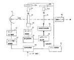
- FIG. 1 is a diagram showing an example of a projector that adjusts the amount of light using an optical aperture.
- the projector of this example includes a lamp 11 serving as a light source, an optical aperture unit 21, a video display device 31, and a projection lens 50.
- the projector also includes a lamp lighting power source 12, a lamp power control unit 13, a motor 22, a motor control unit 23, a dimming control unit 24, a video signal processing unit 32, a signal level detection unit 33, and a fan.
- a control unit 43, cooling fans 42a and 42b, ducts 41a and 41b, and a device control unit 60 are provided.
- the device control unit 60 When the device control unit 60 receives a mode switching instruction by a user operation for operating the projector in either the rated power mode or the power saving mode, the device control unit 60 sends a signal indicating the mode according to the mode switching instruction to the lamp power control unit 13. And notifies the fan control unit 43.
- the lamp power control unit 13 performs control to supply power from the lamp lighting power source 12 to the lamp 11 according to the mode notified from the device control unit 60.
- the lamp lighting power source 12 is controlled to supply the rated power of the lamp 11 to the lamp 11, and the device control unit 60 performs the power saving mode.
- the lamp lighting power source 12 is controlled to supply the lamp 11 with power lower than the rated power of the lamp 11.
- the lamp lighting power source 12 supplies power to the lamp 11 according to the mode in accordance with the mode switching instruction under the control of the lamp power control unit 13.
- the rated power mode the rated power of the lamp 11 is supplied to the lamp 11, and in the power saving mode, power lower than the rated power of the lamp 11 is supplied to the lamp 11.
- the lamp 11 emits illumination light by the electric power supplied from the lamp lighting power source 12.
- the lamp 11 In the rated power mode, the lamp 11 is lit at the rated power, and in the power saving mode, the lamp 11 is lit at a power lower than the rated power of the lamp 11. That is, in the power saving mode, the amount of illumination light emitted from the lamp 11 is smaller than in the rated power mode.
- the fan control unit 43 controls the cooling fans 42a and 42b to rotate at the number of rotations corresponding to the mode notified from the device control unit 60.
- the cooling fans 42a and 42b rotate at a higher rotation speed than when the mode notified from the device control unit 60 is the power saving mode. Control.
- the cooling fans 42a and 42b rotate under the control of the fan control unit 43, and blow cool air to the optical aperture unit 21 and the video display device 31 through the ducts 41a and 41b, respectively. Accordingly, the cooling fans 42 a and 42 b operate as a cooling unit that cools the optical aperture unit 21 and the video display device 31.
- the signal level detection unit 33 detects the signal level of the video signal that is input to the projector and forms an image projected from the projection lens 50.
- the video signal processing unit 32 converts the video signal input to the projector into a signal format corresponding to the video display device 31 and outputs it.
- the video display device 31 is composed of, for example, a liquid crystal panel, and forms a video corresponding to the video signal output from the video signal processing unit 32.
- the dimming control unit 24 calculates the aperture amount of the optical aperture unit 21 according to the signal level detected by the signal level detection unit 33. In the dimming control unit 24, how much light is applied to the video display device 31 according to the signal level of the video signal input to the projector so that the contrast of the video projected from the projection lens 50 becomes a predetermined one. It is decided whether or not it is necessary to irradiate the light. Then, the aperture amount of the optical aperture unit 21 for irradiating the image display device 31 with the light amount is calculated according to the signal level of the image signal.
- the motor control unit 23 controls the motor 22 according to the aperture amount of the optical aperture unit 21 calculated by the dimming control unit 24.
- the motor 22 sets the aperture amount of the optical aperture section 21 under the control of the motor control section 23.
- the optical diaphragm unit 21 is configured such that the diaphragm amount is variable by the motor 22, and the illumination light emitted from the lamp 11 is shielded / passed by the diaphragm amount set by the motor 22.
- the lamp power control unit 13 performs control to supply power from the lamp lighting power source 12 to the lamp 11 according to the mode notified from the device control unit 60. As a result, power corresponding to the mode designated by the user operation is supplied from the lamp lighting power source 12 to the lamp 11 and the lamp 11 is lit.
- the lamp 11 is lit at the rated power
- the power saving mode is designated by the user operation
- the lamp 11 is lit at a power lower than the rated power.
- the power supplied to the lamp 11 is switched according to the mode designated by the user operation.
- the cooling fans 42a and 42b are controlled to rotate at the number of rotations corresponding to the mode notified from the device control unit 60. Thereby, the cooling fans 42a and 42b rotate at the number of rotations corresponding to the mode specified by the user operation.
- the power saving mode is designated by the user operation
- the amount of light emitted from the lamp 11 is smaller than when the rated power mode is designated, so that the optical diaphragm unit 21 and the image display device 31 are irradiated. Less light is generated and less heat is generated. Therefore, when the power saving mode is designated by a user operation, the fan control unit 43 performs control so that the rotational speeds of the cooling fans 42a and 42b are lower than when the rated power mode is designated.
- the rotation speeds of the cooling fans 42a and 42b in the rated power mode and the power saving mode respectively correspond to the heat generation amount or temperature of the optical aperture unit 21 and the video display device 31 in the rated power mode and the power saving mode, respectively. Is set.
- the cooling fans 42a and 42b rotate, the cold air generated by the rotation of the cooling fan 42a is applied to the optical diaphragm 21 via the duct 41a, and the cold air generated by the rotation of the cooling fan 42b is applied via the duct 41b.
- the rotation speed of the cooling fans 42a and 42b is lower in the power saving mode than in the rated power mode, the cold air applied to the optical aperture unit 21 and the video display device 31 is rated power. It becomes weaker in the power saving mode than in the mode.
- the signal level detection unit 33 when a video signal is input, the signal level of the video signal is detected and output to the dimming control unit 24.
- the video signal input to the signal level detection unit 33 is input to the video signal processing unit 32, and the input video signal is converted into a signal format corresponding to the video display device 31 in the video signal processing unit 32. Is output.
- a video is formed based on the video signal output from the video signal processing unit 32.
- the optical diaphragm unit 21 when the signal level of the video signal detected by the signal level detection unit 23 is input, the optical diaphragm unit 21 according to the signal level detected by the signal level detection unit 33.
- the aperture amount is calculated.
- the video display device 31 is set according to the signal level of the video signal input to the projector so that the contrast of the video projected from the projection lens 50 becomes a predetermined contrast. It is determined how much light should be irradiated. Then, the aperture amount of the optical aperture section 21 for irradiating the image display device 31 with the light amount is calculated according to the signal level of the image signal.
- the motor 22 is controlled according to the aperture amount of the optical aperture unit 21 calculated by the dimming control unit 24. Then, the aperture amount of the optical aperture unit 21 is set by the motor 22 to the value calculated by the dimming control unit 24. Thereby, the aperture amount of the optical aperture section 21 is in accordance with the signal level of the video signal input to the projector.
- the illumination light emitted from the lamp 11 is shielded by the optical diaphragm unit 21 by the diaphragm amount corresponding to the video signal, and only the light that has passed through the optical diaphragm unit 21 is passed through the video display device 31 to the projection lens 50. It will be incident on.
- the video formed by the video display device 31 is enlarged and projected onto the screen.
- the aperture amount of the optical aperture section 21 is set according to the signal level of the input video signal, and the illumination light emitted from the lamp 11 is shielded / passed by the aperture amount. By doing so, the contrast of the image enlarged and projected from the projection lens 50 onto the screen is increased.
- the lamp 11 in the power saving mode, the lamp 11 is lit at a power lower than the rated power. Therefore, the lamp 11 also generates heat at the optical aperture unit 21 and the video display device 31. Compared to when it is lit at Therefore, in the power saving mode, the noise caused by the rotation of the cooling fans 42a and 42b can be reduced by rotating the cooling fans 42a and 42b at a low rotational speed. Thereby, the power saving mode also functions as a silent mode with low noise at the same time.
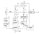
- FIG. 2 is a diagram showing another example of a projector that adjusts the amount of light using an optical aperture.
- the projector of this example has one cooling fan 42 as compared with the projector shown in FIG. 1, and the cool air generated by the cooling fan 42 is transmitted through two ducts 41a and 41b to an optical aperture section. 21 and the video display device 31 are different from each other only.
- the aperture amount of the optical aperture section 21 is set according to the signal level of the input video signal, and the illumination light emitted from the lamp 11 is blocked / passed by the aperture amount, The contrast of the image enlarged and projected from the projection lens 50 onto the screen is increased.
- the optical diaphragm section generates heat because the illumination light emitted from the lamp is shielded by the optical diaphragm section.
- the amount of heat generated by the optical diaphragm increases with the amount of light shielded by the optical diaphragm, and raises the temperature of the optical diaphragm.
- problems such as failure or deterioration of parts occur in terms of reliability. End up. Therefore, as described above, it is conceivable to cool the optical diaphragm unit together with the video display device by the cooling fan.
- the amount of heat generated decreases as the amount of illumination light radiated decreases. Therefore, even if the cooling capacity of the cooling fan is kept low in the power saving mode as described above, the temperature of the parts is extremely high. It won't get expensive.
- former stage of a video display device it will be arrange
- the cooling capacity of the cooling fan is kept low as the amount of illumination light emitted from the lamp decreases in the power saving mode, the temperature of the optical aperture section may increase.
- the ratio of the air flow required for the cooling fan in the mode and the air flow required for the cooling fan in the power saving mode are different. Therefore, for example, as shown in FIG. 2, when cooling air from one cooling fan is applied to each of the components such as the optical aperture unit and the image display device, the cooling fan is cooled in the power saving mode. If the capacity is set in accordance with the heat generation amount or temperature of a component such as a video display device, the temperature of the optical aperture unit will not be high.
- the cooling capacity of the cooling fan in the power saving mode is set according to the heat generation amount or temperature of the optical aperture section, for example, the temperature of the video display device is increased as the cooling capacity of the cooling fan is increased. It becomes too low, causing image quality degradation and noise.
- the present invention provides: A light source having a plurality of modes in which the amount of illumination light emitted is different from each other; Video forming means for forming video according to the video signal; A light shielding means for shielding the illumination light; Projecting means for projecting the image formed by the image forming means using the illumination light that has passed through the light shielding means, The light shielding means and the required cooling capacity are different from each other for each of the plurality of modes, and the cooling parts required for each of the plurality of modes are different from those of the light shielding means.
- Cooling means for cooling with a corresponding cooling capacity;
- Light shielding control means for changing a light shielding rate in the light shielding means according to the video signal,
- the light shielding control unit independently sets a range in which the light shielding rate is changed for each of the plurality of modes.
- the light source is formed by a light source having a plurality of modes in which the amount of illumination light to be emitted is different from each other, an image forming unit that forms an image according to an image signal, a light shielding unit that blocks the illumination light, and the image forming unit
- the projection unit that projects the projected image using the illumination light that has passed through the light blocking unit, the light blocking unit, and the required cooling capacity are different for each of the plurality of modes, and for each of the plurality of modes.
- the light shielding means having different cooling capacity required is a cooling means for cooling a component with a cooling capacity corresponding to the plurality of modes, and a light shielding control for changing a light shielding rate in the light shielding means according to the video signal.
- a dimming control method in a video display device comprising: The light shielding control unit sets a range in which the light shielding rate is changed independently for each of the plurality of modes, and sets the light shielding rate according to the mode and the video signal.
- the temperature of the light shielding means can be appropriately adjusted in the plurality of modes.
- FIG. 3 is a diagram showing an embodiment of the video display device of the present invention.
- the present embodiment is a projector having a lamp 11 serving as a light source, an optical aperture 21 serving as a light shielding unit, a video display device 31 serving as a video forming unit, and a projection lens 50 serving as a projection unit.
- the projector includes a lamp lighting power source 12, a lamp power control unit 13, a motor 22, a motor control unit 23, a dimming control unit 124, a video signal processing unit 32, a signal level detection unit 33, and a fan.
- a control unit 43, a cooling fan 42 serving as a cooling means, a first duct 41a and a second duct 41b, and an apparatus control unit 160 are provided.
- the motor 22, the motor control unit 23, and the dimming control unit 124 constitute the light shielding control means of the present invention.
- the apparatus control unit 160 When the apparatus control unit 160 receives a mode switching instruction by a user operation for operating the projector in either the rated power mode or the power saving mode, the apparatus control unit 160 displays a signal indicating the mode according to the mode switching instruction. 13. Notify the fan control unit 43 and the dimming control unit 124.
- the dimming control unit 124 calculates the aperture amount of the optical aperture unit 21 according to the signal level detected by the signal level detection unit 33 and the mode notified from the device control unit 160.
- the aperture amount of the optical aperture section 21 in this embodiment corresponds to the light blocking rate of the present invention.
- the light blocking ratio is 100%
- the aperture amount of the optical aperture section 21 is In the case where the light emitted from the lamp 11 is the smallest and all light passes therethrough, the light shielding rate is 0%.
- the dimming control unit 124 determines in advance how much light should be irradiated to the video display device 31 in order to make the contrast of the video projected from the projection lens 50 predetermined. Yes. This is determined according to the signal level of the video signal input to the projector for each of the rated power mode and the power saving mode.
- the dimming control unit 124 is a table (LUT: Look) in which the aperture amount of the optical aperture unit 21 for setting the light amount of the illumination light irradiated to the video display device 31 to the determined light amount is set according to the signal level. (Up Table). The table is provided for each of the rated power mode and the power saving mode. Then, the dimming control unit 124 calculates the aperture amount of the optical aperture unit 21 according to the signal level detected by the signal level detection unit 33 and the mode notified from the device control unit 160 based on the table. To do.
- the ducts 41a and 41b are formed based on the heat generation amount or temperature of the optical aperture section 21 and the video display device 31 in the rated power mode.
- the rotation speed of the cooling fan 42 is set according to the heat generation amount or temperature of the video display device 31 in each of the rated power mode and the power saving mode.
- a signal indicating the specified mode is transmitted to the lamp power control unit 13, the fan control unit 43, and the dimming.
- the control unit 124 is notified.
- the lamp power control unit 13 performs control to supply power from the lamp lighting power source 12 to the lamp 11 according to the mode notified from the device control unit 160. As a result, power corresponding to the mode designated by the user operation is supplied from the lamp lighting power source 12 to the lamp 11 and the lamp 11 is lit.
- the lamp 11 is lit at the rated power
- the power saving mode is designated by the user operation
- the lamp 11 is lit at a power lower than the rated power.
- the power supplied to the lamp 11 is switched according to the mode designated by the user operation.
- the cooling fan 42 is controlled to rotate at the number of rotations corresponding to the mode notified from the device control unit 160. Thereby, the cooling fan 42 rotates at the number of rotations corresponding to the mode designated by the user operation.
- the power saving mode is designated by the user operation
- the amount of light emitted from the lamp 11 is smaller than when the rated power mode is designated, so that the optical diaphragm unit 21 and the image display device 31 are irradiated. Less light is generated and less heat is generated. Therefore, the fan control unit 43 performs control so that the rotation speed of the cooling fan 42 is lower when the power saving mode is specified by a user operation than when the rated power mode is specified.
- the rotation speed of the cooling fan 42 in each of the rated power mode and the power saving mode is set according to the amount of heat generated or the temperature of the video display device 31 in each of the rated power mode and the power saving mode.
- the cooling fan 42 rotates, cold air generated by the rotation of the cooling fan 42 is applied to the optical aperture unit 21 through the duct 41a and applied to the video display device 31 through the duct 41b.
- the rotation speed of the cooling fan 42 is lower in the power saving mode than in the rated power mode, the cold air applied to the optical aperture unit 21 and the video display device 31 is in the rated power mode. It is weaker when in power saving mode than when it is.
- the number of pixels included in the range may be detected.
- the output signal level (gradation) of the peak class may be, for example, a minimum value, a maximum value, or a substantially intermediate value in the gradation range.
- the video signal input to the signal level detection unit 33 is input to the video signal processing unit 32, and the input video signal is converted into a signal format corresponding to the video display device 31 in the video signal processing unit 32. Is output.
- a video is formed based on the video signal output from the video signal processing unit 32.
- the dimming control unit 124 when the signal level of the video signal output from the signal level detection unit 23 is input, the signal level output from the signal level detection unit 33 based on the above-described table, The aperture amount of the optical aperture unit 21 corresponding to the mode notified from the device control unit 160 is calculated and output.
- the contrast of the image projected from the projection lens 50 can be adjusted by the amount of light emitted to the image display device 31.
- a predetermined contrast can be obtained by performing the adjustment in accordance with the signal level of the video signal. Therefore, as described above, the dimming control unit 124 controls the video display device according to the signal level of the video signal input to the projector so that the contrast of the video projected from the projection lens 50 becomes a predetermined level. It is determined how much light should be irradiated to the image 31, and the aperture amount of the optical aperture section 21 for setting the light amount irradiated to the image display device 31 to the determined light amount is a signal. It has a table set according to the level. In addition, the dimming control unit 124 according to the present embodiment has a table in which the aperture amount of the optical aperture unit 21 is set according to the signal level in each of the rated power mode and the power saving mode.
- FIG. 4 is a graph showing the relationship between the signal level by the table included in the dimming control unit 124 shown in FIG. 3 and the aperture amount of the optical aperture unit 21.
- the dimming control unit 124 uses the light emitted to the image display device 31.
- the aperture amount of the optical aperture section 21 calculated by the dimming control section 124 changes according to the signal level output from the signal level detection section 33.
- the aperture amount is calculated according to the signal level output from the signal level detection unit 33 within a range between the aperture amount when the signal level is the smallest and the aperture amount when the signal level is the highest. It will be.
- the dimming control unit 124 has a table in which the aperture amount of the optical aperture unit 21 is set according to the signal level for each of the rated power mode and the power saving mode. As shown in FIG. 4, the aperture amount of the optical aperture section 21 corresponding to the signal level is set for each of the rated power mode and the power saving mode.
- the aperture of the optical diaphragm unit 21 according to the range between the diaphragm amount when the signal level is the smallest and the diaphragm amount when the signal level is the largest, that is, the signal level output from the signal level detector 33.
- the range in which the amount is changed is set independently for each of the rated power mode and the power saving mode.
- the optical diaphragm unit 21 receives a large amount of light when the diaphragm amount is large and the light shielding ratio is high. On the other hand, when the aperture amount is small and the light blocking ratio is low, the amount of light received is reduced and the amount of heat generated is reduced. By the way, since the cooling fan 42 has a lower rotational speed in the power saving mode than in the rated power mode, the cooling air applied to the optical aperture 21 is less in the power saving mode than in the rated power mode. Is weaker. Therefore, the dimming control unit 124 is set so that the aperture amount of the optical aperture unit 21 is smaller in the power saving mode than in the rated power mode for the same signal level. As a result, the amount of heat generated in the optical diaphragm 21 is reduced in the power saving mode where the cold air applied to the optical diaphragm 21 is weak.
- the aperture amount of the optical aperture section 21 is for adjusting the contrast of the image projected from the projection lens 50. Therefore, as described above, the aperture amount of the optical aperture section 21 differs for the same signal level. If this happens, the contrast of the image projected from the projection lens 50 may not be a predetermined one.
- the aperture amount of the optical aperture unit 21 in the rated power mode is set so that the contrast of the image projected from the projection lens 50 can obtain a predetermined contrast.
- the aperture amount of the optical aperture section 21 in the mode is set such that the contrast of the image projected from the projection lens 50 is slightly different from the predetermined contrast.
- the motor control unit 23 controls the motor 22 in accordance with the diaphragm amount of the optical diaphragm unit 21 calculated by the light control unit 124. Is done. Then, the aperture amount of the optical diaphragm unit 21 is set by the motor 22 to the value calculated by the light control unit 124.
- the light blocking rate by the aperture amount of the optical aperture unit 21 is in accordance with the signal level of the video signal input to the projector. Then, the illumination light emitted from the lamp 11 is shielded by the optical diaphragm unit 21 at a light shielding rate according to the video signal, and only the light that has passed through the optical diaphragm unit 21 is projected via the video display device 31. It will be incident on.
- the cooling fan 42 is rotated at a rotation speed corresponding to the heat generation amount or temperature of the video display device 31, so that the optical aperture is affected by the radiant heat of the lamp 11. In the part 21, the cooling capacity is insufficient.
- the aperture amount of the optical aperture section 21 is small and the light shielding rate is set low, the heat generation amount of the optical aperture section 21 is reduced, and sufficient cooling is possible.
- the video formed by the video display device 31 is enlarged and projected onto the screen.
- a predetermined contrast can be obtained by performing the control described above for each frame of the video signal.
- the control described above need not be performed for each frame, and may be performed based on the detection results of a plurality of frames.
- the aperture amount of the optical aperture section 21 may be controlled to operate when a frame whose image has the same tendency in the histogram of one frame (for example, a dark image) continues for a predetermined number of times.
- the mode in which the amount of illumination light emitted from the lamp 11 is different has two modes of the rated power mode and the power saving mode has been described as an example.
- the device mode is not limited to two. Three or more modes having different amounts of illumination light emitted from the lamp 11 may be used. Moreover, it is not necessary for one mode among the plurality of modes that the lamp 11 is lit at the rated power.
- the signal level detection unit 33 calculates the aperture amount of the optical aperture unit 21 according to the signal level of the peak class in the histogram of the video signal.
- the number of pixels in the histogram is 1 or more.
- the aperture amount of the optical diaphragm unit 21 may be calculated according to the signal level of the maximum class indicating the maximum gradation (range) or the minimum class indicating the minimum gradation.
- the maximum value, the average value, the minimum value, etc. of the signal level of each pixel for each frame of the video signal are detected.
- the aperture amount of the optical aperture section 21 may be calculated according to the signal level (detection result). Further, the detection of the video signal is performed in units of one frame, but may be performed in a plurality of frames.
- cooling fan 42 for cooling the optical aperture section 21 is shared with the one for cooling the video display device 31, but the cooling fan 42 for cooling the optical aperture section 21 is other than the video display device. It may be configured to be shared with those which cool the parts.
- the configuration shown in FIG. 3 may have two cooling fans 42a and 42b as shown in FIG.
- the ratio of the air volume required when the cooling fan 42a is in the rated power mode and the air volume required when in the power saving mode, and the air volume and power saving of the cooling fan required when the cooling fan 42b is in the rated power mode Since the ratio of the cooling fan air volume required in the mode can be made the same, the control of the cooling means can be simplified, the cooling capacity of the cooling fan 42a can be suppressed, and the increase in noise is prevented. can do.
Landscapes
- Engineering & Computer Science (AREA)
- Multimedia (AREA)
- Signal Processing (AREA)
- Physics & Mathematics (AREA)
- General Physics & Mathematics (AREA)
- Computer Hardware Design (AREA)
- Theoretical Computer Science (AREA)
- Projection Apparatus (AREA)
- Liquid Crystal Display Device Control (AREA)
- Transforming Electric Information Into Light Information (AREA)
- Control Of Indicators Other Than Cathode Ray Tubes (AREA)
Abstract
発する照明光の光量が互いに異なる複数のモードを有する光源(11)と、映像信号に応じた映像を形成する映像形成手段(31)と、映像信号に応じて遮光率を変化させて照明光を遮光する遮光手段(21)と、映像形成手段にて形成された映像を、遮光手段を通過した照明光を用いて投射する投射手段(50)と、映像形成手段及び遮光手段を複数のモードに応じたそれぞれ異なる冷却能力によって冷却する冷却手段(42)とを有し、遮光手段における遮光率を変化させる範囲が複数のモード毎に独立に設定されている。
Description
本発明は、光源からの光を用いて映像を投射する映像表示装置に関し、特に、光源からの光を遮光する技術に関する。
光源からの光を用いて映像を投射するプロジェクターにおいて、映像のコントラストを高める方法として、光学絞りにより光量調節を行う方法が知られている(例えば、特許文献1参照)。
図1は、光学絞りにより光量調節を行うプロジェクターの一例を示す図である。
本例のプロジェクターは図1に示すように、光源となるランプ11と、光学絞り部21と、映像表示デバイス31と、投射レンズ50とを有する。また、プロジェクターは、ランプ点灯電源12と、ランプ電力制御部13と、モーター22と、モーター制御部23と、調光制御部24と、映像信号処理部32と、信号レベル検出部33と、ファン制御部43と、冷却ファン42a,42bと、ダクト41a,41bと、装置制御部60とを有している。
装置制御部60は、プロジェクターを定格電力モードと省電力モードとのいずれかで動作させるためのユーザー操作によるモード切替指示を受け付けると、モード切替指示に従ったモードを示す信号をランプ電力制御部13及びファン制御部43に通知する。
ランプ電力制御部13は、装置制御部60から通知されたモードに応じた電力をランプ点灯電源12からランプ11に供給する制御を行う。装置制御部60から定格電力モードであることが通知された場合は、ランプ点灯電源12にランプ11に対してランプ11の定格電力を供給させる制御を行わせ、装置制御部60から省電力モードであることが通知された場合は、ランプ点灯電源12にランプ11に対してランプ11の定格電力よりも低い電力を供給させる制御を行わせる。
ランプ点灯電源12は、ランプ電力制御部13の制御によって、モード切替指示に従ったモードに応じた電力をランプ11に供給する。定格電力モードにおいては、ランプ11に対してランプ11の定格電力を供給し、省電力モードにおいては、ランプ11に対してランプ11の定格電力よりも低い電力を供給する。
ランプ11は、ランプ点灯電源12から供給された電力によって照明光を発する。定格電力モードにおいては、ランプ11の定格電力で点灯し、省電力モードにおいては、ランプ11の定格電力よりも低い電力で点灯する。つまり、省電力モードにおいては、定格電力モードよりもランプ11が発する照明光の光量が少なくなる。
ファン制御部43は、冷却ファン42a,42bが、装置制御部60から通知されたモードに応じた回転数で回転するように制御する。装置制御部60から通知されたモードが定格電力モードである場合は、装置制御部60から通知されたモードが省電力モードである場合よりも高い回転数で冷却ファン42a,42bが回転するように制御する。
冷却ファン42a,42bは、ファン制御部43の制御によって回転し、ダクト41a,41bを介して冷風を光学絞り部21及び映像表示デバイス31のそれぞれに吹き付ける。これにより、冷却ファン42a,42bは、光学絞り部21と映像表示デバイス31を冷却する冷却手段として動作する。
信号レベル検出部33は、プロジェクターに入力され、投射レンズ50から投射される映像を形成するための映像信号の信号レベルを検出する。
映像信号処理部32は、プロジェクターに入力された映像信号を映像表示デバイス31に応じた信号形式に変換して出力する。
映像表示デバイス31は、例えば、液晶パネルからなり、映像信号処理部32から出力された映像信号に応じた映像を形成する。
調光制御部24は、信号レベル検出部33にて検出された信号レベルに応じて光学絞り部21の絞り量を算出する。調光制御部24においては、投射レンズ50から投射された映像のコントラストが所定のものとなるように、プロジェクターに入力された映像信号の信号レベルに応じて、映像表示デバイス31にどれだけの光量の光が照射されればよいかが決められている。そして、その光量の光を映像表示デバイス31に照射するための光学絞り部21の絞り量が映像信号の信号レベルに応じて算出される。
モーター制御部23は、調光制御部24にて算出された光学絞り部21の絞り量に応じてモーター22を制御する。
モーター22は、モーター制御部23の制御によって光学絞り部21の絞り量を設定する。
光学絞り部21は、モーター22によってその絞り量が可変となるように構成されており、モーター22によって設定された絞り量によって、ランプ11にて発せられた照明光を遮光/通過する。
以下に、上記のように構成されたプロジェクターの動作について説明する。
ユーザー操作によって、定格電力モードと省電力モードのいずれかの指定が装置制御部60を介して行われると、指定されたモードを示す信号が、ランプ電力制御部13及びファン制御部43に通知される。
ランプ電力制御部13において、装置制御部60から通知されたモードに応じた電力をランプ点灯電源12からランプ11に供給する制御が行われる。それにより、ランプ点灯電源12から、ユーザー操作によって指定されたモードに応じた電力がランプ11に供給されてランプ11が点灯する。ユーザー操作によって定格電力モードが指定された場合は、ランプ11がその定格電力で点灯し、ユーザー操作によって省電力モードが指定された場合は、ランプ11がその定格電力よりも低い電力で点灯する。このように、ランプ電力制御部13において、ランプ11に供給される電力が、ユーザー操作によって指定されたモードによって切り替えられる。
また、ファン制御部43において、冷却ファン42a,42bが、装置制御部60から通知されたモードに応じた回転数で回転する制御が行われる。それにより、冷却ファン42a,42bは、ユーザー操作によって指定されたモードに応じた回転数で回転する。ユーザー操作によって省電力モードが指定された場合は、定格電力モードが指定された場合に比べて、ランプ11にて発せられる光の光量が少ないことから、光学絞り部21及び映像表示デバイス31に照射される光量も少なく発熱量も少ない。そのため、ファン制御部43は、ユーザー操作によって省電力モードが指定された場合は、定格電力モードが指定された場合に比べて、冷却ファン42a,42bの回転数を低くするように制御を行う。
なお、定格電力モードと省電力モードのそれぞれにおける冷却ファン42a,42bの回転数は、定格電力モードと省電力モードのそれぞれにおける光学絞り部21、映像表示デバイス31の発熱量または温度に応じてそれぞれ設定されている。冷却ファン42a,42bが回転すると、冷却ファン42aの回転による冷風が、ダクト41aを介して光学絞り部21に当てられるとともに、冷却ファン42bの回転による冷風が、ダクト41bを介して映像表示デバイス31に当てられる。冷却ファン42a,42bの回転数が、上述したように、定格電力モードのときよりも省電力モードのときの方が低いため、光学絞り部21及び映像表示デバイス31に当てられる冷風は、定格電力モードのときよりも省電力モードのときの方が弱くなる。
信号レベル検出部33においては、映像信号が入力されると、映像信号の信号レベルが検出され、調光制御部24に出力される。また、信号レベル検出部33に入力された映像信号は、映像信号処理部32に入力され、映像信号処理部32において、入力された映像信号が映像表示デバイス31に応じた信号形式に変換されて出力される。
映像表示デバイス31においては、映像信号処理部32から出力された映像信号に基づいて映像が形成される。
また、調光制御部24においては、信号レベル検出部23にて検出された映像信号の信号レベルが入力されると、信号レベル検出部33にて検出された信号レベルに応じて光学絞り部21の絞り量が算出される。上述したように、調光制御部24においては、投射レンズ50から投射された映像のコントラストが所定のものとなるように、プロジェクターに入力された映像信号の信号レベルに応じて、映像表示デバイス31にどれだけの光量の光が照射されればよいかが決められている。そして、その光量の光を映像表示デバイス31に照射するための光学絞り部21の絞り量が映像信号の信号レベルに応じて算出されることになる。
モーター制御部23において、調光制御部24にて算出された光学絞り部21の絞り量に応じてモーター22が制御される。そして、モーター22によって光学絞り部21の絞り量が、調光制御部24にて算出されたものに設定される。これにより、光学絞り部21の絞り量が、プロジェクターに入力された映像信号の信号レベルに応じたものとなる。
そして、ランプ11にて発せられた照明光が、映像信号に応じた絞り量によって光学絞り部21にて遮光され、光学絞り部21を通過した光のみが映像表示デバイス31を介して投影レンズ50に入射されることになる。
光学絞り部21を通過した光が映像表示デバイス31を介して投影レンズ50に入射されると、映像表示デバイス31にて形成された映像がスクリーンに拡大投射される。
このように、本例のプロジェクターにおいては、入力された映像信号の信号レベルに応じて光学絞り部21の絞り量を設定し、絞り量によって、ランプ11にて発せられた照明光を遮光/通過させることにより、投射レンズ50からスクリーンに拡大投射される映像のコントラストを高めている。
図1に示したプロジェクターにおいては、省電力モードのときは、ランプ11が定格電力よりも低い電力で点灯することになるため、光学絞り部21及び映像表示デバイス31の発熱もランプ11が定格電力で点灯する場合と比べて少ないものとなる。そのため、省電力モードのときは、冷却ファン42a,42bも低い回転数で回転させることにより、冷却ファン42a,42bの回転による騒音を低減することができる。これにより、省電力モードは、同時に騒音が低い静音モードとしても機能する。
図2は、光学絞りにより光量調節を行うプロジェクターの他の例を示す図である。
本例のプロジェクターは図2に示すように、図1に示したものに対して、冷却ファン42が1つであって、その冷却ファン42による冷風を、2つのダクト41a,41bによって光学絞り部21と映像表示デバイス31のそれぞれに当てている点のみが異なるものである。
本例のプロジェクターにおいても、入力された映像信号の信号レベルに応じて光学絞り部21の絞り量を設定し、絞り量によって、ランプ11にて発せられた照明光を遮光/通過させることにより、投射レンズ50からスクリーンに拡大投射される映像のコントラストを高めている。
上述したプロジェクターのような映像表示装置においては、ランプにて発した照明光を光学絞り部において遮光するため、光学絞り部が発熱する。光学絞り部の発熱量は、光学絞り部にて遮光される光量に応じて大きくなり、光学絞り部の温度を上げる。このとき、光学絞り部として樹脂からなるものを用いた場合、あるいは、光学絞り部の周囲に樹脂からなる部品を配置した場合に、信頼性の面において、部品の故障や劣化等の問題が生じてしまう。そこで、上述したように、冷却ファンによって映像表示デバイスとともに光学絞り部を冷却することが考えられる。
映像表示デバイス等の部品は、照射される照明光の光量が少なくなると発熱量も下がるため、上述したような省電力モードにて冷却ファンによる冷却能力が低く抑えられても、部品の温度が著しく高くなってしまうことはない。一方、光学絞り部は、映像表示デバイスの前段に配置する必要があることから、ランプの近傍に配置されることとなる。そのため、光学絞り部の発熱量は、光学絞り部にて遮光される光量だけではなく、ランプによる輻射熱の影響を受ける。一般に、ランプの温度は、定格電力モードや省電力モード等のモードによらず、略一定に保たれるように制御される。そのため、省電力モードのときにランプから発せられる照明光の光量が下がっても、ランプによる輻射熱の影響はほとんど変化しない。そのため、省電力モード時にランプから発せられる照明光の光量が下がることに伴って、冷却ファンによる冷却能力が低く抑えられてしまうと、光学絞り部の温度が高くなってしまうことがある。
上記のように、映像表示デバイス等の部品における、定格電力モードのときに必要な冷却ファンの風量と省電力モードのときに必要な冷却ファンの風量との割合と、光学絞り部における、定格電力モードのときに必要な冷却ファンの風量と省電力モードのときに必要な冷却ファンの風量との割合とが異なる。そのため、例えば、図2に示したように、1つの冷却ファンによる冷風を、光学絞り部と映像表示デバイス等の部品のそれぞれに当てているような場合、省電力モードのときの冷却ファンの冷却能力を、映像表示デバイス等の部品の発熱量または温度に合わせて設定すると、光学絞り部の温度が高くなくなってしまう。また、省電力モードのときの冷却ファンの冷却能力を、光学絞り部の発熱量または温度に合わせて設定すると、冷却ファンの冷却能力を高くすることに伴って、例えば、映像表示デバイスの温度が低くなりすぎて画質劣化を引き起こしたり、騒音も高くなってしまったりすることになる。
そこで、光学絞り部を冷却する冷却ファンを他の冷却ファンとは別個に設け、これらを独立に制御することが考えられる。ところが、その場合、コストが高くなることや、上記と同様に騒音が高くなる等の問題がある。
本発明は、上述したような技術が有する問題点を解決することができる映像表示装置及び調光制御方法を提供することを目的とする。
上記目的を達成するために本発明は、
発する照明光の光量が互いに異なる複数のモードを有する光源と、
映像信号に応じた映像を形成する映像形成手段と、
前記照明光を遮光する遮光手段と、
前記映像形成手段にて形成された映像を、前記遮光手段を通過した前記照明光を用いて投射する投射手段と、
前記遮光手段と、必要となる冷却能力が前記複数のモード毎に互いに異なり、かつ、前記複数のモード毎に必要となる冷却能力が前記遮光手段とは異なる構成部品と、を前記複数のモードに応じた冷却能力によって冷却する冷却手段と、
前記映像信号に応じて前記遮光手段における遮光率を変化させる遮光制御手段とを有し、
前記遮光制御手段は、前記遮光率を変化させる範囲を、前記複数のモード毎に独立に設定している。
発する照明光の光量が互いに異なる複数のモードを有する光源と、
映像信号に応じた映像を形成する映像形成手段と、
前記照明光を遮光する遮光手段と、
前記映像形成手段にて形成された映像を、前記遮光手段を通過した前記照明光を用いて投射する投射手段と、
前記遮光手段と、必要となる冷却能力が前記複数のモード毎に互いに異なり、かつ、前記複数のモード毎に必要となる冷却能力が前記遮光手段とは異なる構成部品と、を前記複数のモードに応じた冷却能力によって冷却する冷却手段と、
前記映像信号に応じて前記遮光手段における遮光率を変化させる遮光制御手段とを有し、
前記遮光制御手段は、前記遮光率を変化させる範囲を、前記複数のモード毎に独立に設定している。
また、発する照明光の光量が互いに異なる複数のモードを有する光源と、映像信号に応じた映像を形成する映像形成手段と、前記照明光を遮光する遮光手段と、前記映像形成手段にて形成された映像を、前記遮光手段を通過した前記照明光を用いて投射する投射手段と、前記遮光手段と、必要となる冷却能力が前記複数のモード毎に互いに異なり、かつ、前記複数のモード毎に必要となる冷却能力が異なる前記遮光手段とは構成部品とを、前記複数のモードに応じた冷却能力によって冷却する冷却手段と、前記映像信号に応じて前記遮光手段における遮光率を変化させる遮光制御手段とを有してなる映像表示装置における調光制御方法であって、
前記遮光制御手段が、前記遮光率を変化させる範囲を前記複数のモード毎に独立に設定しておき、前記モード及び前記映像信号に応じて前記遮光率を設定する。
前記遮光制御手段が、前記遮光率を変化させる範囲を前記複数のモード毎に独立に設定しておき、前記モード及び前記映像信号に応じて前記遮光率を設定する。
本発明によれば、前記複数のモードにおいて遮光手段の温度を適切に調整することができる。
以下に、本発明の実施の形態について図面を参照して説明する。
図3は、本発明の映像表示装置の実施の一形態を示す図である。
本形態は図3に示すように、光源となるランプ11と、遮光手段となる光学絞り部21と、映像形成手段となる映像表示デバイス31と、投射手段となる投射レンズ50とを有するプロジェクターである。また、プロジェクターは、ランプ点灯電源12と、ランプ電力制御部13と、モーター22と、モーター制御部23と、調光制御部124と、映像信号処理部32と、信号レベル検出部33と、ファン制御部43と、冷却手段となる冷却ファン42と、第1のダクト41a及び第2のダクト41bと、装置制御部160とを有している。モーター22、モーター制御部23及び調光制御部124から、本願発明の遮光制御手段が構成される。
なお、図3に示した構成要素のうち、図1及び図2に示した構成要素と同じ符号を付与しているものは、図1及び図2を用いて説明したその構成要素の動作と同じ動作をする。
装置制御部160は、プロジェクターを定格電力モードと省電力モードとのいずれかで動作させるためのユーザー操作によるモード切替指示を受け付けると、モード切替指示に従ったモードを示す信号を、ランプ電力制御部13、ファン制御部43及び調光制御部124に通知する。
調光制御部124は、信号レベル検出部33にて検出された信号レベルと、装置制御部160から通知されたモードとに応じて光学絞り部21の絞り量を算出する。なお、本形態における光学絞り部21の絞り量は、本発明の光の遮光率に相当する。光学絞り部21の絞り量が、最も大きく、ランプ11にて発せられた光が全く通過しないものである場合は、光の遮光率が100%となり、また、光学絞り部21の絞り量が、最も小さく、ランプ11にて発せられた光が全て通過するものである場合は、光の遮光率が0%となる。
調光制御部124においては、投射レンズ50から投射された映像のコントラストを所定のものとするためには、映像表示デバイス31にどれだけの光量の光が照射されればよいかが予め決められている。これは、定格電力モードと省電力モードのそれぞれについて、プロジェクターに入力された映像信号の信号レベルに応じて決められている。調光制御部124は、映像表示デバイス31に照射される照明光の光量をその決められた光量とするための光学絞り部21の絞り量が信号レベルに応じて設定されたテーブル(LUT:Look Up Table)を有している。テーブルは、定格電力モードと省電力モードのそれぞれについて設けられている。そして、調光制御部124は、テーブルに基づいて、信号レベル検出部33にて検出された信号レベルと、装置制御部160から通知されたモードとに応じた光学絞り部21の絞り量を算出する。
ダクト41a,41bは、定格電力モードのときの光学絞り部21および映像表示デバイス31の発熱量または温度に基づいて形成される。
冷却ファン42の回転数は、定格電力モードと省電力モードのそれぞれにおける映像表示デバイス31の発熱量または温度に応じて設定されている。
以下に、上記のように構成されたプロジェクターの動作について説明する。
ユーザー操作によって、定格電力モードと省電力モードのいずれかの指定が装置制御部160を介して行われると、指定されたモードを示す信号が、ランプ電力制御部13、ファン制御部43及び調光制御部124に通知される。
ランプ電力制御部13において、装置制御部160から通知されたモードに応じた電力をランプ点灯電源12からランプ11に供給する制御が行われる。それにより、ランプ点灯電源12から、ユーザー操作によって指定されたモードに応じた電力がランプ11に供給されてランプ11が点灯する。ユーザー操作によって定格電力モードが指定された場合は、ランプ11がその定格電力で点灯し、ユーザー操作によって省電力モードが指定された場合は、ランプ11がその定格電力よりも低い電力で点灯する。このように、ランプ電力制御部13において、ランプ11に供給される電力が、ユーザー操作によって指定されたモードによって切り替えられる。
また、ファン制御部43において、冷却ファン42が、装置制御部160から通知されたモードに応じた回転数で回転する制御が行われる。それにより、冷却ファン42は、ユーザー操作によって指定されたモードに応じた回転数で回転する。ユーザー操作によって省電力モードが指定された場合は、定格電力モードが指定された場合に比べて、ランプ11にて発せられる光の光量が少ないことから、光学絞り部21及び映像表示デバイス31に照射される光量も少なく発熱量も少ない。そのため、ファン制御部43は、ユーザー操作によって省電力モードが指定された場合は、定格電力モードが指定された場合に比べて、冷却ファン42の回転数が低くするように制御を行う。なお、定格電力モードと省電力モードのそれぞれにおける冷却ファン42の回転数は、定格電力モードと省電力モードのそれぞれにおける映像表示デバイス31の発熱量または温度に応じて設定されている。冷却ファン42が回転すると、冷却ファン42の回転による冷風が、ダクト41aを介して光学絞り部21に当てられるとともに、ダクト41bを介して映像表示デバイス31に当てられる。冷却ファン42の回転数が、上述したように、定格電力モードのときよりも省電力モードのときの方が低いため、光学絞り部21及び映像表示デバイス31に当てられる冷風は、定格電力モードのときよりも省電力モードのときの方が弱くなる。
信号レベル検出部33においては、映像信号が入力されると、映像信号の信号レベルが検出され、調光制御部24に出力される。具体的には、信号レベル検出部33において、まず、入力された映像信号1フレーム分の各画素の信号レベル(階調)と画素数との関係を示すヒストグラムが検出される。そして、信号レベル検出部33において、検出されたヒストグラムの画素数のピーク値を示す階調がピーク階級として検出され、ピーク階級の信号レベル(階調)が出力される。なお、検出されるヒストグラムは、ここでは1階調毎に画素数を検出しているが、全階調を、例えば、4階調毎や8階調毎に分割して、分割された階調の範囲に含まれる画素数を検出してもよい。この場合、出力されるピーク階級の信号レベル(階調)は、例えば、その階調の範囲の最小値、最大値、または、略中間の値としてもよい。また、信号レベル検出部33に入力された映像信号は、映像信号処理部32に入力され、映像信号処理部32において、入力された映像信号が映像表示デバイス31に応じた信号形式に変換されて出力される。
映像表示デバイス31においては、映像信号処理部32から出力された映像信号に基づいて映像が形成される。
また、調光制御部124においては、信号レベル検出部23から出力された映像信号の信号レベルが入力されると、上述したテーブルに基づいて、信号レベル検出部33から出力された信号レベルと、装置制御部160から通知されたモードとに応じた光学絞り部21の絞り量が算出されて出力される。
投射レンズ50から投射された映像のコントラストは、映像表示デバイス31に照射される光の光量によって調整することができる。そして、その調整を映像信号の信号レベルに応じて行うことにより、所定のコントラストを得ることができるようになる。そこで、上述したように、調光制御部124は、投射レンズ50から投射された映像のコントラストが所定のものとなるように、プロジェクターに入力された映像信号の信号レベルに応じて、映像表示デバイス31にどれだけの光量の光が照射されればよいかが決められており、映像表示デバイス31に照射される光の光量をその決められた光量とするための光学絞り部21の絞り量が信号レベルに応じて設定されたテーブルを有している。また、本形態の調光制御部124は、光学絞り部21の絞り量が信号レベルに応じて設定されたテーブルを、定格電力モードと省電力モードのそれぞれについて有している。
図4は、図3に示した調光制御部124が有するテーブルによる信号レベルと光学絞り部21の絞り量との関係を示すグラフである。
上述したように、投射レンズ50から投射された映像のコントラストを、映像表示デバイス31に照射される光の光量によって調整するために、調光制御部124は、映像表示デバイス31に照射される光の光量をその決められた光量とするための光学絞り部21の絞り量が信号レベルに応じて設定されたテーブルを有している。
そのため、図4に示すように、調光制御部124にて算出される光学絞り部21の絞り量は、信号レベル検出部33から出力された信号レベルに応じて変化するものとなっている。そして、信号レベルが最も小さな場合の絞り量と信号レベルが最も大きな場合の絞り量との間の範囲内にて、信号レベル検出部33から出力された信号レベルに応じて絞り量が算出されることになる。また、上述したように、調光制御部124は、光学絞り部21の絞り量が信号レベルに応じて設定されたテーブルを、定格電力モードと省電力モードのそれぞれについて有しているため、図4に示すように、信号レベルに応じた光学絞り部21の絞り量が、定格電力モードと省電力モードのそれぞれについて設定されている。それにより、信号レベルが最も小さな場合の絞り量と信号レベルが最も大きな場合の絞り量との間の範囲、すなわち、信号レベル検出部33から出力された信号レベルに応じて光学絞り部21の絞り量を変化させる範囲が、定格電力モードと省電力モードのそれぞれについて独立に設定されている。
ここで、定格電力モードと省電力モードとにおける光学絞り部21の絞り量について説明する。
光学絞り部21は、絞り量が大きく遮光率が高いと、それだけ多くの光を受けることから発熱量が多くなる。一方、絞り量が小さく遮光率が低いと、受ける光が少なくなって発熱量が少なくなる。ところで、冷却ファン42は、その回転数が、定格電力モードのときよりも省電力モードのときの方が低いため、光学絞り部21に当てられる冷風は、定格電力モードのときよりも省電力モードのときの方が弱くなる。そこで、調光制御部124においては、同一の信号レベルについて、定格電力モードのときよりも省電力モードのときの方が、光学絞り部21の絞り量が小さくなるように設定されている。それにより、光学絞り部21に当てられる冷風が弱い省電力モードのときにおいて、光学絞り部21における発熱量を低減している。
なお、光学絞り部21の絞り量は、投射レンズ50から投射された映像のコントラストを調整するためのものであるため、上述したように、同一の信号レベルについて光学絞り部21の絞り量が異なってしまうと、投射レンズ50から投射された映像のコントラストが所定のものとならなくなってしまう虞れがある。本形態の調光制御部124においては、定格電力モードのときにおける光学絞り部21の絞り量を、投射レンズ50から投射された映像のコントラストが所定のコントラストを得ることができるものとし、省電力モードのときにおける光学絞り部21の絞り量を、投射レンズ50から投射された映像のコントラストが所定のコントラストとは若干異なる程度のものとしている。
調光制御部124にて光学絞り部21の絞り量が算出されると、モーター制御部23において、調光制御部124にて算出された光学絞り部21の絞り量に応じてモーター22が制御される。そして、モーター22によって光学絞り部21の絞り量が、調光制御部124にて算出されたものに設定される。
それにより、光学絞り部21の絞り量による光の遮光率が、プロジェクターに入力された映像信号の信号レベルに応じたものとなる。そして、ランプ11にて発せられた照明光が、映像信号に応じた遮光率によって光学絞り部21にて遮光され、光学絞り部21を通過した光のみが映像表示デバイス31を介して投影レンズ50に入射されることになる。この際、プロジェクターが省電力モードで動作していると、冷却ファン42が映像表示デバイス31の発熱量または温度に応じた回転数で回転しているため、ランプ11の輻射熱の影響を受ける光学絞り部21においては、冷却能力が不足する。しかし、省電力モードのときにおいては、光学絞り部21の絞り量が小さく遮光率が低く設定されているため、光学絞り部21の発熱量が少なくなり、十分な冷却が可能となる。
光学絞り部21を通過した光が映像表示デバイス31を介して投影レンズ50に入射されると、映像表示デバイス31にて形成された映像がスクリーンに拡大投射される。
上述した制御が映像信号の1フレーム毎に行われることにより、所定のコントラストを得ることができる。ただし、上述した制御は、1フレーム毎に行う必要はなく、複数のフレームの検出結果に基づいて行っても良い。例えば、1フレームのヒストグラムが同じ傾向の画像(例えば、暗い画像)であるフレームが所定の回数連続したときに、光学絞り部21の絞り量を動作させるように制御しても良い。
上述したように本形態においては、遮光手段における遮光率を変化させる範囲が、前記複数のモード毎に独立に設定されているため、省電力モード等の冷却手段の冷却能力が低いモードにおいても、遮光手段における遮光率が低くなるような範囲を設定することにより、遮光手段の温度が著しく高くなってしまうことがなく、騒音を高めることなく遮光手段の温度を適切に調整することができる。具体的には、ランプ11にて発せられる照明光の光量と冷却ファン42の冷却能力とに応じて、光学絞り部21の絞り量による遮光率が設定される範囲を互いに異なるように設定することによって、発生する熱量と冷却能力とのバランスを確保している。それにより、光学絞り部21を冷却する冷却ファンを他の部品を冷却する冷却ファンと共用化しても、冷却ファンの回転数を高くする必要がなく、安価で、低騒音のプロジェクターを提供することができる。
なお、本形態においては、ランプ11にて発せられる照明光の光量が異なるモードとして定格電力モードと省電力モードとの2つのモードを有する場合を例に挙げて説明したが、本発明の映像表示装置のモードは2つに限らない。ランプ11にて発せられる照明光の光量が異なる3つ以上もモードを有するものであってもよい。また、複数のモードのうち、1つのモードが、ランプ11が定格電力で点灯するものである必要はない。
また、本形態においては、信号レベル検出部33において、映像信号のヒストグラムにおけるピーク階級の信号レベルに応じて光学絞り部21の絞り量を算出しているが、ヒストグラムにおける画素数が1以上となる階調(範囲)のうち、最大の階調(範囲)を示す最大階級や最小の階調を示す最小階級の信号レベルに応じて光学絞り部21の絞り量を算出してもよい。また、ヒストグラムにおける信号レベルに応じて光学絞り部21の絞り量を算出するのではなく、映像信号の1フレーム毎の各画素の信号レベルの最大値、平均値、最小値等を検出し、これらの信号レベル(検出結果)に応じて光学絞り部21の絞り量を算出してもよい。また、映像信号の検出は、1フレーム単位でおこなったが、複数のフレームで行っても良い。
また、光学絞り部21を冷却するための冷却ファン42を、映像表示デバイス31を冷却するためのものと共用しているが、光学絞り部21を冷却するための冷却ファン42を映像表示デバイス以外の部品を冷却するものと共用する構成であってもよい。
また、図3に示した構成において、図1に示したもののように、2つの冷却ファン42a,42bを有するものとしてもよい。その場合、冷却ファン42aの定格電力モードのときに必要な風量と省電力モードのときに必要な風量との割合と、冷却ファン42bの定格電力モードのときに必要な冷却ファンの風量と省電力モードのときに必要な冷却ファンの風量との割合とを同じにできるので、冷却手段の制御が簡単になり、また、冷却ファン42aの冷却能力を抑えることができ、騒音が高くなることを防止することができる。
Claims (8)
- 発する照明光の光量が互いに異なる複数のモードを有する光源と、
映像信号に応じた映像を形成する映像形成手段と、
前記照明光を遮光する遮光手段と、
前記映像形成手段にて形成された映像を、前記遮光手段を通過した前記照明光を用いて投射する投射手段と、
前記遮光手段と、必要となる冷却能力が前記複数のモード毎に互いに異なり、かつ、前記複数のモード毎に必要となる冷却能力が前記遮光手段とは異なる構成部品とを、前記複数のモードに応じた冷却能力によって冷却する冷却手段と、
前記映像信号に応じて前記遮光手段における遮光率を変化させる遮光制御手段とを有し、
前記遮光制御手段は、前記遮光率を変化させる範囲を、前記複数のモード毎に独立に設定している映像表示装置。 - 請求項1に記載の映像表示装置において、
前記複数のモードのうち、前記光源の発する照明光の光量が少ないモードが、他のモードよりも、前記冷却手段の冷却能力が低く設定され、かつ、前記遮光率の最大値が低く設定されている映像表示装置。 - 請求項2に記載の映像表示装置において、
前記冷却手段の冷却能力は、前記複数のモードのそれぞれにおける前記構成部品の発熱量または温度に応じて設定されている映像表示装置。 - 請求項1乃至3のいずれか1項に記載の映像表示装置において、
前記構成部品は、前記映像形成手段である映像表示装置。 - 請求項1乃至4のいずれか1項に記載の映像表示装置において、
前記映像信号の信号レベルを検出して検出結果を出力する信号レベル検出手段を有し、
前記遮光制御手段は、前記遮光手段における遮光率を、前記信号レベル検出手段から出力された検出結果に応じて設定する映像表示装置。 - 請求項1乃至5のいずれか1項に記載の映像表示装置において、
前記冷却手段は、前記構成部品及び前記遮光手段を1つの冷却ファンによって冷却する映像表示装置。 - 請求項6に記載の映像表示装置において、
前記遮光手段に冷風を導く第1のダクトと、
前記構成部品に冷風を導く第2のダクトと、をさらに有し、
前記第1のダクトと第2のダクトは、前記複数のモードのうち最大の光量となるモードのときの、前記遮光手段および前記構成部品の発熱量または温度に基づいて形成されている映像表示装置。 - 発する照明光の光量が互いに異なる複数のモードを有する光源と、映像信号に応じた映像を形成する映像形成手段と、前記照明光を遮光する遮光手段と、前記映像形成手段にて形成された映像を、前記遮光手段を通過した前記照明光を用いて投射する投射手段と、前記遮光手段と、必要となる冷却能力が前記複数のモード毎に互いに異なり、かつ、前記複数のモード毎に必要となる冷却能力が前記遮光手段とは異なる構成部品とを、前記複数のモードに応じた冷却能力によって冷却する冷却手段と、前記映像信号に応じて前記遮光手段における遮光率を変化させる遮光制御手段とを有してなる映像表示装置における調光制御方法であって、
前記遮光制御手段が、前記遮光率を変化させる範囲を前記複数のモード毎に独立に設定しておき、前記モード及び前記映像信号に応じて前記遮光率を設定する、調光制御方法。
Priority Applications (2)
| Application Number | Priority Date | Filing Date | Title |
|---|---|---|---|
| JP2015504056A JP6061360B2 (ja) | 2013-03-06 | 2013-03-06 | 映像表示装置及び調光制御方法 |
| PCT/JP2013/056146 WO2014136223A1 (ja) | 2013-03-06 | 2013-03-06 | 映像表示装置及び調光制御方法 |
Applications Claiming Priority (1)
| Application Number | Priority Date | Filing Date | Title |
|---|---|---|---|
| PCT/JP2013/056146 WO2014136223A1 (ja) | 2013-03-06 | 2013-03-06 | 映像表示装置及び調光制御方法 |
Publications (1)
| Publication Number | Publication Date |
|---|---|
| WO2014136223A1 true WO2014136223A1 (ja) | 2014-09-12 |
Family
ID=51490786
Family Applications (1)
| Application Number | Title | Priority Date | Filing Date |
|---|---|---|---|
| PCT/JP2013/056146 Ceased WO2014136223A1 (ja) | 2013-03-06 | 2013-03-06 | 映像表示装置及び調光制御方法 |
Country Status (2)
| Country | Link |
|---|---|
| JP (1) | JP6061360B2 (ja) |
| WO (1) | WO2014136223A1 (ja) |
Citations (4)
| Publication number | Priority date | Publication date | Assignee | Title |
|---|---|---|---|---|
| JP2005031572A (ja) * | 2003-07-11 | 2005-02-03 | Sharp Corp | プロジェクターの画質補正システム |
| WO2006132167A1 (ja) * | 2005-06-08 | 2006-12-14 | Matsushita Electric Industrial Co., Ltd. | 画像表示装置 |
| JP2008046572A (ja) * | 2006-08-21 | 2008-02-28 | Sony Corp | 表示装置およびその駆動方法 |
| JP2011203514A (ja) * | 2010-03-25 | 2011-10-13 | Seiko Epson Corp | プロジェクター |
-
2013
- 2013-03-06 JP JP2015504056A patent/JP6061360B2/ja not_active Expired - Fee Related
- 2013-03-06 WO PCT/JP2013/056146 patent/WO2014136223A1/ja not_active Ceased
Patent Citations (4)
| Publication number | Priority date | Publication date | Assignee | Title |
|---|---|---|---|---|
| JP2005031572A (ja) * | 2003-07-11 | 2005-02-03 | Sharp Corp | プロジェクターの画質補正システム |
| WO2006132167A1 (ja) * | 2005-06-08 | 2006-12-14 | Matsushita Electric Industrial Co., Ltd. | 画像表示装置 |
| JP2008046572A (ja) * | 2006-08-21 | 2008-02-28 | Sony Corp | 表示装置およびその駆動方法 |
| JP2011203514A (ja) * | 2010-03-25 | 2011-10-13 | Seiko Epson Corp | プロジェクター |
Also Published As
| Publication number | Publication date |
|---|---|
| JPWO2014136223A1 (ja) | 2017-02-09 |
| JP6061360B2 (ja) | 2017-01-18 |
Similar Documents
| Publication | Publication Date | Title |
|---|---|---|
| JP5455275B2 (ja) | 画像表示装置および光源冷却方法 | |
| US7131731B2 (en) | Projection type video display apparatus | |
| WO2014155571A1 (ja) | 投写型表示装置および投写型表示装置の制御方法 | |
| JP4582264B1 (ja) | 投写型表示装置 | |
| JP4238640B2 (ja) | 照明装置、投射型表示装置及びその駆動方法 | |
| JP2000352708A (ja) | 液晶表示装置 | |
| US8960922B2 (en) | Projector and control method of the same | |
| JP6061360B2 (ja) | 映像表示装置及び調光制御方法 | |
| US10948809B2 (en) | Image projection apparatus, its control method, and storage medium | |
| US20180224728A1 (en) | Image display apparatus and image display system using the same | |
| JP5213080B2 (ja) | プロジェクタ装置およびその光源電力制御方法 | |
| US10264227B2 (en) | Projection-type image display device | |
| JP2018049205A (ja) | 液晶プロジェクタ装置 | |
| JP2018013656A (ja) | 投射型表示装置 | |
| JP2009069679A (ja) | プロジェクタ | |
| TWI436153B (zh) | 投影機及相關控制方法 | |
| US9417510B2 (en) | Image projection device and method of controlling image projection device | |
| JP6469477B2 (ja) | 電子機器及び表示制御方法 | |
| JP2018049207A (ja) | 液晶プロジェクタ装置 | |
| US20150322955A1 (en) | Optimization of heat regulation in a device comprising a fan | |
| JP4966565B2 (ja) | 照明光の調光に応じた液晶パネルの対向電極電圧の動的調整 | |
| JP4998573B2 (ja) | 照明光の調光に応じた液晶パネルの対向電極電圧の動的調整 | |
| JP2015225213A (ja) | 画像投射装置およびその制御プログラム | |
| JP2011118152A (ja) | 投射型表示装置 | |
| JP2005284126A (ja) | 投射型表示装置 |
Legal Events
| Date | Code | Title | Description |
|---|---|---|---|
| 121 | Ep: the epo has been informed by wipo that ep was designated in this application |
Ref document number: 13876886 Country of ref document: EP Kind code of ref document: A1 |
|
| ENP | Entry into the national phase |
Ref document number: 2015504056 Country of ref document: JP Kind code of ref document: A |
|
| NENP | Non-entry into the national phase |
Ref country code: DE |
|
| 122 | Ep: pct application non-entry in european phase |
Ref document number: 13876886 Country of ref document: EP Kind code of ref document: A1 |