WO2014136179A1 - アドレス設定システム及びアドレス設定方法 - Google Patents
アドレス設定システム及びアドレス設定方法 Download PDFInfo
- Publication number
- WO2014136179A1 WO2014136179A1 PCT/JP2013/055838 JP2013055838W WO2014136179A1 WO 2014136179 A1 WO2014136179 A1 WO 2014136179A1 JP 2013055838 W JP2013055838 W JP 2013055838W WO 2014136179 A1 WO2014136179 A1 WO 2014136179A1
- Authority
- WO
- WIPO (PCT)
- Prior art keywords
- light
- address
- emitting device
- light emitting
- setting system
- Prior art date
- Legal status (The legal status is an assumption and is not a legal conclusion. Google has not performed a legal analysis and makes no representation as to the accuracy of the status listed.)
- Ceased
Links
Images


Classifications
-
- H—ELECTRICITY
- H05—ELECTRIC TECHNIQUES NOT OTHERWISE PROVIDED FOR
- H05B—ELECTRIC HEATING; ELECTRIC LIGHT SOURCES NOT OTHERWISE PROVIDED FOR; CIRCUIT ARRANGEMENTS FOR ELECTRIC LIGHT SOURCES, IN GENERAL
- H05B47/00—Circuit arrangements for operating light sources in general, i.e. where the type of light source is not relevant
- H05B47/10—Controlling the light source
- H05B47/175—Controlling the light source by remote control
- H05B47/198—Grouping of control procedures or address assignation to light sources
-
- H—ELECTRICITY
- H05—ELECTRIC TECHNIQUES NOT OTHERWISE PROVIDED FOR
- H05B—ELECTRIC HEATING; ELECTRIC LIGHT SOURCES NOT OTHERWISE PROVIDED FOR; CIRCUIT ARRANGEMENTS FOR ELECTRIC LIGHT SOURCES, IN GENERAL
- H05B47/00—Circuit arrangements for operating light sources in general, i.e. where the type of light source is not relevant
- H05B47/10—Controlling the light source
- H05B47/175—Controlling the light source by remote control
- H05B47/18—Controlling the light source by remote control via data-bus transmission
Definitions
- the present invention relates to an address setting system and an address setting method.
- Patent Document 1 describes setting addresses of a plurality of lighting devices by the following method. First, a logical address is set in advance for each of the plurality of lighting devices. The plurality of logical addresses are stored in the control device in advance. Then, the control device turns on the lighting devices one by one using the logical address. The control device recognizes the physical address of the lighting device that is turned on by analyzing the image captured by the imaging device. Thereby, the control device can associate the logical address with the physical address. The logical address is set when the lighting device is shipped from the factory.
- the control device needs to store in advance identification information (logical address) preset in a plurality of light emitting devices. For this reason, when the identification information of a light-emitting device cannot be memorize
- An example of a problem to be solved by the present invention is that the address used in the control device is made to correspond to the position of the light emitting device without storing the identification information of the light emitting device in the control device in advance.
- a light irradiating unit configured to irradiate at least one of the plurality of light emitting devices with identifying light for identifying the light emitting device selected from the plurality of light emitting devices
- An address information transmission unit for transmitting address information to the light emitting device identified by the identifying light; It is an address setting system provided with.
- the light-emitting device for which an address is to be set is selected from a plurality of light-emitting devices, and the identifying light for specifying the selected light-emitting device is assigned to at least one of the plurality of light-emitting devices.
- address information is set to the light emitting device by transmitting address information to the light emitting device selected by the specifying light.
- FIG. 10 is a diagram illustrating a configuration of an address setting system according to a third embodiment.
- each component of each control unit indicates a functional unit block, not a hardware unit configuration.
- the components of each control unit are an arbitrary computer CPU, memory, a program loaded in the memory, a storage medium such as a hard disk for storing the program, and an arbitrary combination of hardware and software centering on a network connection interface. It is realized by. There are various modifications of the implementation method and apparatus.
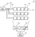
- FIG. 1 is a diagram illustrating a configuration of an address setting system 10 according to the embodiment.
- the address setting system 10 includes a light irradiation unit 140 and an address information transmission unit 150, and is a system for setting an address for each of a plurality of installed light emitting devices 100.
- the plurality of light emitting devices 100 are controlled by the light emission control unit 120.
- the light irradiation unit 140 irradiates at least one of the plurality of light emitting devices 100 with identification light that identifies the light emitting device 100 selected from the plurality of light emitting devices 100. Then, the address information transmission unit 150 transmits the address information to the light emitting device 100 specified by the specifying light. Therefore, the address used in the light emission control unit 120 can correspond to the position of the light emitting device 100 without storing the identification information of the light emitting device 100 in the light emission control unit 120 in advance.
- an example of the configuration of the address setting system 10 will be specifically described.
- the address setting system 10 has a plurality of light emitting devices 100 to be set.
- the plurality of light emitting devices 100 are arranged in a matrix.
- the light emitting device 100 has, for example, an organic EL or LED as a light source.
- the light source included in the light emitting device 100 is not limited to these.
- the light emitting device 100 is connected to the light emission control unit 120 via the power line 122 and the control line 124.
- the light emission control unit 120 controls light emission of the plurality of light emitting devices 100 using addresses set for each of the plurality of light emitting devices 100.
- the addresses used here are set in the plurality of light emitting devices 100 using the address setting system 10.
- the light emitting device 100 includes a light receiving unit 102 and a device side control unit 104.
- the light receiving unit 102 photoelectrically converts light from the outside to generate an electrical signal.
- the address information transmission unit 150 irradiates a plurality of light emitting devices 100 with setting modulated light modulated based on address information to be set in the light emitting devices 100.
- the apparatus-side control unit 104 converts the setting modulation light emitted from the address information transmission unit 150 into an electrical signal.
- the device-side control unit 104 recognizes address information by processing this electric signal, and stores this address information as an address of the light emitting device 100.
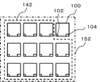
- FIG. 2 is a diagram for explaining the light irradiation range by the light irradiation unit 140 and the address information transmission unit 150.
- the address information transmission unit 150 irradiates the plurality of light emitting devices 100 with the setting modulation light 152. For this reason, the same address is set in the plurality of light emitting devices 100 as it is.
- the light irradiation unit 140 includes the light emitting device 100 to which the address information transmitted from the address information transmitting unit 150 is to be set among the plurality of light emitting devices 100 (in the example illustrated in FIG. 2, the upper right corner).
- the light (specific light) 142 is irradiated on the light emitting devices 100 except the light emitting device 100).
- the apparatus side control part 104 of light-emitting devices 100 other than the desired light-emitting device 100 cannot recognize an address. Therefore, the address can be set only for the desired light emitting device 100. Further, when the light receiving unit 102 detects light of a certain level or higher, the apparatus side control unit 104 may not set an address.
- the light irradiation unit 140 and the address information transmission unit 150 are controlled by the setting control unit 160.
- the setting control unit 160 stores an address for each installation position of each of the plurality of light emitting devices 100 in advance.
- the setting control unit 160 controls the light irradiation unit 140 and the address information transmission unit 150 to set addresses for each of the plurality of light emitting devices 100 as predetermined. Note that the address used here is also stored in the light emission control unit 120.
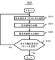
- FIG. 3 is a flowchart illustrating an example of control performed by the setting control unit 160.
- the processing shown in this figure is performed after the address setting system 10 enters the address setting mode.
- the setting control unit 160 selects the light emitting device 100 to set an address, and reads the position and address of the light emitting device 100 from a recording medium (not shown) such as a memory (step S10).
- the setting control unit 160 controls the irradiation region of the light irradiation unit 140 based on the read information, and the light emitting device 100 excluding the light emitting device 100 for which an address is to be set among the plurality of light emitting devices 100 is specified. Irradiate light (step S20).
- the setting control unit 160 controls the address information transmitting unit 150 to irradiate the plurality of light emitting devices 100 with the setting modulated light generated using the read address (step S30).
- the address information included in the modulated light for setting can be recognized only by the light emitting device 100 that is not irradiated with the light from the light irradiation unit 140 among the plurality of light emitting devices 100. Thereby, a desired address can be set to the desired light emitting device 100.
- the setting control unit 160 performs the address setting process shown in steps S10 to S30 for all the light emitting devices 100 (step S40).
- the light emitting device 100 to which an address is to be set is selected by the specifying light emitted from the light irradiation unit 140. Then, the address information transmission unit 150 transmits the address information to the light emitting device 100 specified by the specifying light. Therefore, the address used in the light emission control unit 120 can correspond to the position of the light emission device 100 without storing the identification information of the light emitting device 100 in the light emission control unit 120 in advance.
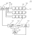
- FIG. 4 is a diagram illustrating the configuration of the address setting system 10 according to the first embodiment.
- the address setting system 10 according to the present embodiment has the same configuration as the address setting system 10 according to the embodiment except for the following points.
- the light emitting device 100 displays the address recognition information indicating that the address information has been recognized by the address setting system 10. It transmits to the setting control part 160.
- the setting control unit 160 controls the light irradiation unit 140 to change the light emitting device 100 specified by the specifying light, and the address information transmission unit 150 transmits. The address is changed to an address corresponding to the changed light emitting device 100.
- the device-side control unit 104 of the light emitting device 100 changes the light emission state of the light emitting device 100 when the address setting is completed.
- the device-side control unit 104 may change the light emitting device 100 from a non-light emitting state to a light emitting state, or may change the light emitting device 100 from a constantly emitting light state to a blinking state.
- the address setting system 10 has a light emission analysis unit 170.
- the light emission analysis unit 170 analyzes the light emission state of each of the plurality of light emitting devices 100.
- the light emission analysis unit 170 includes, for example, an image sensor and an image processing unit. Then, the light emission analysis unit 170 recognizes from the change in the light emission state of the light emitting device 100 that the setting of the address of the light emitting device 100 has been completed.
- the light emission analysis unit 170 transmits the recognition result to the setting control unit 160.
- the light emission analysis unit 170 may identify each position of the light emitting device 100 by capturing and analyzing the entire image of the plurality of light emitting devices 100.
- the setting control unit 160 controls the irradiation range (or irradiation destination) of the specifying light by using the positions of the plurality of light emitting devices 100 recognized by the light emission analysis unit 170, and the setting process is performed at that time. It is possible to make the light emitting device 100 corresponding to the address being performed recognize that it is an address setting target. In this way, addresses can be allocated according to a predetermined rule.
- the light emitting device 100 fails to recognize the address information within a predetermined time, the light emitting device 100 transmits address unrecognized information indicating that the address information could not be recognized to the setting control unit 160 of the address setting system 10. To do.
- Such a case may be, for example, the case where the address setting does not end even if a predetermined time has elapsed since the address setting system 10 entered the address setting mode.
- the address information transmitting unit 150 transmits the address again. Note that the transmission of the address unrecognized information may be performed by a change in the light emission state of the light emitting device 100, similarly to the address recognition information.
- FIG. 5 is a flowchart showing the operation of the setting control unit 160 according to the present embodiment. The process shown in this figure is the same as the process described with reference to FIG. 3 in the embodiment except for the following points.
- step S30 After the address information transmission unit 150 transmits the modulated light for setting indicating the address information (step S30), the setting control unit 160 indicates that the address setting is completed based on the recognition result transmitted from the light emission analysis unit 170. (Step S35: Yes), the process proceeds to step S40. If the recognition result transmitted from the light emission analysis unit 170 indicates that the address setting has failed (step S35: No), the process returns to step S30, and the address information transmission unit 150 again receives the address information. To send. At this time, if the number of address setting failures reaches a predetermined number, it is determined that an abnormality has occurred in the address setting system 10, and the process is terminated (step S36).
- the device side control unit 104 of the light emitting device 100 transmits the address recognition information and the address unrecognized information described above via the light emission control unit 120. May be transmitted to the setting control unit 160.
- the same effect as in the embodiment can be obtained.
- the light emitting device 100 transmits the address setting success / failure to the setting control unit 160.
- the setting control unit 160 can proceed to the address setting of the next light emitting device 100 only when the address setting is successful. Therefore, it is possible to reduce the possibility that the process is ended without setting an address in any of the light emitting devices 100.
- FIG. 6 is a diagram illustrating the configuration of the address setting system 10 according to the second embodiment.
- the address setting system 10 according to the present embodiment has the same configuration as the address setting system 10 according to the embodiment or the first embodiment except for the following points. This figure shows the same case as in the first embodiment.
- the address information transmission unit 150 also serves as the light irradiation unit 140. Then, the address information transmission unit 150 transmits the setting modulation light only to the light emitting device 100 in which the address information is to be set. In this case, the address information transmitting unit 150 generates setting modulation light, for example, by modulating a laser.
- the same effect as in the embodiment or example 1 can be obtained. Moreover, since it is not necessary to provide the light irradiation part 140, the manufacturing cost of the address setting system 10 becomes low.
- FIG. 7 is a diagram illustrating the configuration of the address setting system 10 according to the third embodiment.
- the address setting system 10 according to the present embodiment has the same configuration as the address setting system 10 according to the embodiment or the first embodiment except for the following points. This figure shows the same case as in the first embodiment.
- the address information transmission unit 150 transmits the address information to be set to all the light emitting devices 100 via the light emission control unit 120 and the control line 124.
- the light irradiation unit 140 irradiates the specific light only to the light emitting device 100 that is the target of address information setting.
- the device-side control unit 104 of the light emitting device 100 takes in the address information flowing through the control line 124 at that time and stores it as the address of the light emitting device 100.
- the light irradiation unit 140 may be configured not to irradiate the light for specifying only the light emitting device 100 that is the target of address information setting. In this case, when the light receiving unit 102 does not detect the identifying light, the device-side control unit 104 of the light emitting device 100 takes in the address information flowing through the control line 124 at that time, and the address of the light emitting device 100 Remember as.
- the address information may be transmitted from the light emission control unit 120.
- the address information transmission unit 150 outputs information indicating that address information to be output to the control line 124 is switched to the light emission control unit 120, for example.
Landscapes
- Circuit Arrangement For Electric Light Sources In General (AREA)
Abstract
光照射部(140)は、複数の発光装置(100)から選択された発光装置(100)を特定する特定用光を、複数の発光装置(100)の少なくとも一つに向けて照射する。そしてアドレス情報送信部(150)は、特定用光で特定された発光装置(100)にアドレス情報を送信する。このため、発光装置(100)の識別情報を予め発光制御部(120)に記憶させなくても、発光制御部(120)で用いるアドレスを発光装置(100)の位置に対応させることができる。
Description
本発明は、アドレス設定システム及びアドレス設定方法に関する。
有機EL(organic electroluminescence)パネルやLED(Light Emitting Diode)パネルなどのパネル状の発光源を複数並べて配置し、一つの発光装置として使用する場合がある。このような発光装置では、複数の発光源を制御することにより、様々な形態で照明を行うことが可能になる。
一方で、複数の発光装置を制御するためには、各々の発光装置に、制御部で用いるアドレスを設定する必要がある。例えば特許文献1には、以下の方法によって複数の照明装置のアドレスを設定することが記載されている。まず、複数の照明装置のそれぞれには、予め論理アドレスが設定されている。これら複数の論理アドレスは、予め制御装置に記憶されている。そして制御装置は、論理アドレスを用いて照明装置を一つずつ点灯させる。制御装置は、撮像装置が撮像した画像を解析することにより、点灯した照明装置の物理アドレスを認識する。これにより、制御装置は、論理アドレスと物理アドレスを対応付けることができる。なお、論理アドレスは、照明装置が工場から出荷されるときに設定されている。
特許文献1に記載の技術では、制御装置は複数の発光装置に予め設定された識別情報(論理アドレス)を予め記憶しておく必要がある。このため、発光装置の識別情報を予め制御装置に記憶させることができない場合、制御装置で用いるアドレスを発光装置の位置に対応させることはできない。
本発明が解決しようとする課題としては、発光装置の識別情報を予め制御装置に記憶させなくても、制御装置で用いるアドレスを発光装置の位置に対応させることが一例として挙げられる。
請求項1に記載の発明は、複数の発光装置から選択された前記発光装置を特定する特定用光を、前記複数の発光装置の少なくとも一つに向けて照射する光照射部と、
前記特定用光で特定された前記発光装置にアドレス情報を送信するアドレス情報送信部と、
を備えるアドレス設定システムである。
前記特定用光で特定された前記発光装置にアドレス情報を送信するアドレス情報送信部と、
を備えるアドレス設定システムである。
請求項11に記載の発明は、複数の発光装置からアドレスを設定すべき前記発光装置を選択し、選択された前記発光装置を特定する特定用光を、前記複数の発光装置の少なくとも一つに向けて照射し、
前記特定用光で選択された発光装置にアドレス情報を送信することにより、前記発光装置にアドレスを設定するアドレス設定方法である。
前記特定用光で選択された発光装置にアドレス情報を送信することにより、前記発光装置にアドレスを設定するアドレス設定方法である。
上述した目的、およびその他の目的、特徴および利点は、以下に述べる好適な実施の形態、およびそれに付随する以下の図面によってさらに明らかになる。
以下、本発明の実施の形態について、図面を用いて説明する。尚、すべての図面において、同様な構成要素には同様の符号を付し、適宜説明を省略する。
なお、以下に示す説明において、各制御部の各構成要素は、ハードウエア単位の構成ではなく、機能単位のブロックを示している。各制御部の構成要素は、任意のコンピュータのCPU、メモリ、メモリにロードされたプログラム、そのプログラムを格納するハードディスクなどの記憶メディア、ネットワーク接続用インタフェースを中心にハードウエアとソフトウエアの任意の組合せによって実現される。そして、その実現方法、装置には様々な変形例がある。
(実施形態)
図1は、実施形態に係るアドレス設定システム10の構成を示す図である。アドレス設定システム10は、光照射部140及びアドレス情報送信部150を備えており、設置済みの複数の発光装置100のそれぞれにアドレスを設定するためのシステムである。複数の発光装置100は、発光制御部120によって制御されている。
図1は、実施形態に係るアドレス設定システム10の構成を示す図である。アドレス設定システム10は、光照射部140及びアドレス情報送信部150を備えており、設置済みの複数の発光装置100のそれぞれにアドレスを設定するためのシステムである。複数の発光装置100は、発光制御部120によって制御されている。
光照射部140は、複数の発光装置100から選択された発光装置100を特定する特定用光を、複数の発光装置100の少なくとも一つに向けて照射する。そしてアドレス情報送信部150は、特定用光で特定された発光装置100にアドレス情報を送信する。このため、発光装置100の識別情報を予め発光制御部120に記憶させなくても、発光制御部120で用いるアドレスを発光装置100の位置に対応させることができる。以下、アドレス設定システム10の構成の一例を具体的に説明する。
アドレス設定システム10は、設定対象の複数の発光装置100を有している。複数の発光装置100はマトリクス状に配置されている。発光装置100は、光源として、例えば有機EL又はLEDを有している。ただし発光装置100が有する光源はこれらに限定されない。
発光装置100は、電力線122及び制御線124を介して発光制御部120に接続している。発光制御部120は、複数の発光装置100のそれぞれに設定されたアドレスを用いて、複数の発光装置100の発光を制御する。ここで用いられるアドレスは、アドレス設定システム10を用いて複数の発光装置100に設定される。
また発光装置100は、受光部102及び装置側制御部104を備えている。受光部102は、外部からの光を光電変換して電気信号を生成する。アドレス情報送信部150は、発光装置100に設定すべきアドレス情報に基づいて変調した設定用変調光を複数の発光装置100に向けて照射する。装置側制御部104は、アドレス情報送信部150から照射された設定用変調光を電気信号に変換する。装置側制御部104は、この電気信号を処理することによりアドレス情報を認識し、このアドレス情報をその発光装置100のアドレスとして記憶する。
図2は、光照射部140及びアドレス情報送信部150による光の照射範囲を説明するための図である。本図に示す例において、アドレス情報送信部150は、複数の発光装置100に設定用変調光152を照射する。このため、このままでは複数の発光装置100に同一のアドレスが設定されてしまう。これを防止するために、光照射部140は、複数の発光装置100のうち、アドレス情報送信部150から送信されているアドレス情報が設定されるべき発光装置100(図2に示す例では右上隅の発光装置100)を除いた発光装置100に、光(特定用光)142を照射する。すると、特定用光142が照射された発光装置100においては、受光部102から出力される信号のS/N(Signal to Noise)比が低下する。このため、所望する発光装置100以外の発光装置100の装置側制御部104は、アドレスを認識できない。従って、所望する発光装置100にのみ、そのアドレスを設定することができる。また、受光部102が一定レベル以上の光を検出した場合に装置側制御部104がアドレスを設定しないようにしてもよい。
なお、光照射部140及びアドレス情報送信部150は、設定制御部160によって制御されている。設定制御部160は、予め複数の発光装置100それぞれの設置位置別にアドレスを記憶している。設定制御部160は、光照射部140及びアドレス情報送信部150を制御することにより、複数の発光装置100のそれぞれに、予め定められた通りにアドレスを設定する。なお、ここで用いられるアドレスは、発光制御部120にも記憶されている。
図3は、設定制御部160が行う制御の一例を示すフローチャートである。本図に示す処理は、アドレス設定システム10がアドレス設定モードになってから行われる。まず、設定制御部160は、アドレスを設定すべき発光装置100を選択し、その発光装置100の位置及びアドレスをメモリーなどの記録媒体(図示せず)から読み出す(ステップS10)。次いで設定制御部160は、読み出した情報に基づいて光照射部140の照射領域を制御し、複数の発光装置100のうちアドレスが設定されるべき発光装置100を除いた発光装置100に、特定用光を照射する(ステップS20)。
次いで設定制御部160は、アドレス情報送信部150を制御し、読み出したアドレスを用いて生成した設定用変調光を、複数の発光装置100に照射する(ステップS30)。この状態で設定用変調光に含まれるアドレス情報を認識できるのは、複数の発光装置100のうち、光照射部140からの光が照射されていない発光装置100のみである。これにより、所望する発光装置100に所望するアドレスを設定することができる。
そして設定制御部160は、全ての発光装置100に対して、ステップS10~S30に示したアドレス設定処理を行う(ステップS40)。
以上、本実施形態によれば、アドレスが設定されるべき発光装置100は、光照射部140から照射される特定用光によって選択される。そしてアドレス情報送信部150は、特定用光で特定された発光装置100に対してアドレス情報を送信する。従って、発光装置100の識別情報を予め発光制御部120に記憶させなくても、発光制御部120で用いるアドレスを発光装置100の位置に対応させることができる。
(実施例1)
図4は、実施例1に係るアドレス設定システム10の構成を示す図である。本実施例に係るアドレス設定システム10は、以下の点を除いて、実施形態に係るアドレス設定システム10と同様の構成である。
図4は、実施例1に係るアドレス設定システム10の構成を示す図である。本実施例に係るアドレス設定システム10は、以下の点を除いて、実施形態に係るアドレス設定システム10と同様の構成である。
まず、発光装置100は、光照射部140からの光(特定用光)によって選択された後、アドレス情報を認識できた場合、アドレス情報を認識したことを示すアドレス認識情報をアドレス設定システム10の設定制御部160に送信する。そしてアドレス設定システム10がアドレス認識情報を認識したとき、設定制御部160は、光照射部140を制御し、特定用光が特定する発光装置100を変更し、且つアドレス情報送信部150が送信するアドレスを、変更後の発光装置100に対応するアドレスに変更する。
本図に示す例では、発光装置100の装置側制御部104は、アドレスの設定が完了すると、その発光装置100の発光状態を変化させる。例えば装置側制御部104は、その発光装置100を未発光状態から発光状態に変化させても良いし、発光装置100を常時発光している状態から点滅する状態に変化させても良い。
そしてアドレス設定システム10は、発光解析部170を有している。発光解析部170は、複数の発光装置100のそれぞれの発光状態を解析する。発光解析部170は、例えば画像センサと画像処理部によって構成される。そして発光解析部170は、発光装置100の発光状態の変化から、その発光装置100のアドレスの設定が終了したことを認識する。発光解析部170は、認識結果を設定制御部160に送信する。
なお、発光解析部170は、複数の発光装置100の全体の像を取り込んだ上で解析することにより、発光装置100のそれぞれの位置を特定してもよい。この場合、設定制御部160は、発光解析部170が認識した複数の発光装置100それぞれの位置を用いて特定用光の照射範囲(又は照射先)を制御することにより、そのときに設定処理が行われているアドレスに対応する発光装置100に、アドレスの設定対象であることを認識させることができる。このようにすると、あらかじめ決められたルールでアドレスを割り振ることができる。
また、発光装置100は、予め定められた時間以内にアドレス情報を認識できなかった場合、アドレス情報を認識できなかったことを示すアドレス未認識情報を、アドレス設定システム10の設定制御部160に送信する。このようなケースは、例えば、アドレス設定システム10がアドレス設定モードになってから予め定められた時間経過してもアドレスの設定が終了しない場合などがある。
そしてアドレス設定システム10がアドレス未認識情報を認識したとき、アドレス情報送信部150は、アドレスを再度送信する。なお、アドレス未認識情報の送信は、アドレス認識情報と同様に、発光装置100の発光状態の変化によって行われても良い。
図5は、本実施例に係る設定制御部160の動作を示すフローチャートである。本図に示す処理は、以下の点を除いて、実施形態において図3を用いて説明した処理と同様である。
アドレス情報送信部150がアドレス情報を示す設定用変調光を送信した(ステップS30)後、設定制御部160は、発光解析部170から送信されてくる認識結果が、アドレス設定が完了していることを示していた場合(ステップS35:Yes)、ステップS40に進む。また、発光解析部170から送信されてくる認識結果が、アドレス設定が失敗していることを示していた場合(ステップS35:No)、ステップS30に戻り、アドレス情報送信部150に、再度アドレス情報を送信させる。このとき、アドレス設定の失敗回数が予め定められた回数に達した場合、アドレス設定システム10に異常が生じていると判断し、処理を終了する(ステップS36)。
なお、例えば設定制御部160と発光制御部120の間で通信が行われる場合、発光装置100の装置側制御部104は、上述したアドレス認識情報及びアドレス未認識情報を、発光制御部120を介して設定制御部160に送信しても良い。
本実施例によっても、実施形態と同様の効果を得ることができる。また、発光装置100は、アドレスの設定の成功/失敗を、設定制御部160に送信する。このため、設定制御部160は、アドレスの設定が成功した場合にのみ、次の発光装置100のアドレスの設定に進むようにすることができる。従って、いずれかの発光装置100にアドレスが設定されないで処理が終了する可能性を低くすることができる。
(実施例2)
図6は、実施例2に係るアドレス設定システム10の構成を示す図である。本実施例に係るアドレス設定システム10は、以下の点を除いて、実施形態又は実施例1に係るアドレス設定システム10と同様の構成である。本図は、実施例1と同様の場合を示している。
図6は、実施例2に係るアドレス設定システム10の構成を示す図である。本実施例に係るアドレス設定システム10は、以下の点を除いて、実施形態又は実施例1に係るアドレス設定システム10と同様の構成である。本図は、実施例1と同様の場合を示している。
まず、アドレス情報送信部150は光照射部140を兼ねている。そして、アドレス情報送信部150は、そのアドレス情報が設定されるべき発光装置100にのみ、設定用変調光を送信する。この場合、アドレス情報送信部150は、例えばレーザを変調することにより、設定用変調光を生成する。
本実施例によっても、実施形態又は実施例1と同様の効果を得ることができる。また、光照射部140を設ける必要はないため、アドレス設定システム10の製造コストは低くなる。
(実施例3)
図7は、実施例3に係るアドレス設定システム10の構成を示す図である。本実施例に係るアドレス設定システム10は、以下の点を除いて、実施形態又は実施例1に係るアドレス設定システム10と同様の構成である。本図は、実施例1と同様の場合を示している。
図7は、実施例3に係るアドレス設定システム10の構成を示す図である。本実施例に係るアドレス設定システム10は、以下の点を除いて、実施形態又は実施例1に係るアドレス設定システム10と同様の構成である。本図は、実施例1と同様の場合を示している。
まず、アドレス情報送信部150は、設定対象となっているアドレス情報を、発光制御部120及び制御線124を介して全ての発光装置100に送信する。
そして、光照射部140は、アドレス情報の設定対象となっている発光装置100にのみ、特定用光を照射する。受光部102が特定用光を検出した場合、その発光装置100の装置側制御部104は、そのとき制御線124を流れているアドレス情報を取り込んで、その発光装置100のアドレスとして記憶する。
なお、光照射部140は、実施形態と同様に、アドレス情報の設定対象となっている発光装置100にのみ、特定用光を照射しないようにしてもよい。この場合、受光部102が特定用光を検出していない場合、その発光装置100の装置側制御部104は、そのとき制御線124を流れているアドレス情報を取り込んで、その発光装置100のアドレスとして記憶する。
なお、アドレス情報は発光制御部120から送信されても良い。この場合、アドレス情報送信部150は、例えば制御線124に出力するアドレス情報を切り替えることを示す情報を、発光制御部120に出力する。
本実施例によっても、実施形態又は実施例1と同様の効果を得ることができる。
以上、図面を参照して実施形態及び実施例について述べたが、これらは本発明の例示であり、上記以外の様々な構成を採用することもできる。
Claims (11)
- 複数の発光装置から選択された前記発光装置を特定する特定用光を、前記複数の発光装置の少なくとも一つに向けて照射する光照射部と、
前記特定用光で特定された前記発光装置にアドレス情報を送信するアドレス情報送信部と、
を備えるアドレス設定システム。 - 請求項1に記載のアドレス設定システムにおいて、
前記発光装置は、前記アドレス情報を認識した場合に、前記アドレス情報を認識したことを示すアドレス認識情報を前記アドレス設定システムに送信し、
前記アドレス認識情報を認識したとき、
前記光照射部は、前記特定用光が特定する前記発光装置を変更し、
前記アドレス情報送信部は、変更後の前記発光装置のアドレス情報を送信するアドレス設定システム。 - 請求項2に記載のアドレス設定システムにおいて、
前記発光装置は、前記アドレス情報を認識した場合、発光状態を変更することにより、前記アドレス認識情報を前記アドレス設定システムに送信し、
前記発光装置の発光から前記アドレス認識情報を検出する発光解析部を備えるアドレス設定システム。 - 請求項1~3のいずれか一項に記載のアドレス設定システムにおいて、
前記発光解析部は、画像処理によって前記複数の発光装置のそれぞれの位置を特定する画像処理部を備え、
前記光照射部は、前記画像処理部が特定した位置に基づいて前記特定用光の照射を制御するアドレス設定システム。 - 請求項1~4のいずれか一項に記載のアドレス設定システムにおいて、
前記発光装置は、予め定められた時間が経過した後、前記アドレス情報を認識できなかった場合に、前記アドレス情報を認識できなかったことを示すアドレス未認識情報を前記アドレス設定システムに送信し、
前記アドレス情報送信部は、前記アドレス未認識情報を受信したときに、再度前記アドレス情報をすくなくとも所定回数送信するアドレス設定システム。 - 請求項5に記載のアドレス設定システムにおいて、
前記発光装置は、予め定められた時間が経過した後、前記アドレス情報を認識できなかった場合、発光状態を変更することにより、前記アドレス未認識情報を前記アドレス設定システムに送信し、
前記発光装置の発光から前記アドレス未認識情報を検出する発光解析部を備えるアドレス設定システム。 - 請求項1~6のいずれか一項に記載のアドレス設定システムにおいて、
前記アドレス情報送信部は、前記アドレス情報に基づいて変調した設定用変調光を前記複数の発光装置に向けて照射し、
前記光照射部は、前記設定用変調光が照射されている間、前記複数の発光装置のうち前記選択された発光装置を除いた前記発光装置に、前記特定用光を照射するアドレス設定システム。 - 請求項1~6のいずれか一項に記載のアドレス設定システムにおいて、
前記アドレス情報送信部は、前記光照射部を兼ねており、前記特定用光として、前記アドレス情報に基づいて変調した設定用変調光を前記選択された発光装置に向けて照射するアドレス設定システム。 - 請求項1~6のいずれか一項に記載のアドレス設定システムにおいて、
前記光照射部は、前記特定用光を前記選択された発光装置に向けて照射し、
前記アドレス情報送信部は、前記複数の発光装置に前記アドレス情報を出力し、
前記発光装置は、
前記特定用光を検出する受光部と、
前記受光部が前記特定用光を検出したときに、前記アドレス情報を記憶する制御部と、
を備えるアドレス設定システム。 - 請求項1~9のいずれか一項に記載のアドレス設定システムにおいて、
前記複数の発光装置を有するアドレス設定システム。 - 複数の発光装置からアドレスを設定すべき前記発光装置を選択し、選択された前記発光装置を特定する特定用光を、前記複数の発光装置の少なくとも一つに向けて照射し、
前記特定用光で選択された発光装置にアドレス情報を送信することにより、前記発光装置にアドレスを設定するアドレス設定方法。
Priority Applications (1)
| Application Number | Priority Date | Filing Date | Title |
|---|---|---|---|
| PCT/JP2013/055838 WO2014136179A1 (ja) | 2013-03-04 | 2013-03-04 | アドレス設定システム及びアドレス設定方法 |
Applications Claiming Priority (1)
| Application Number | Priority Date | Filing Date | Title |
|---|---|---|---|
| PCT/JP2013/055838 WO2014136179A1 (ja) | 2013-03-04 | 2013-03-04 | アドレス設定システム及びアドレス設定方法 |
Publications (1)
| Publication Number | Publication Date |
|---|---|
| WO2014136179A1 true WO2014136179A1 (ja) | 2014-09-12 |
Family
ID=51490748
Family Applications (1)
| Application Number | Title | Priority Date | Filing Date |
|---|---|---|---|
| PCT/JP2013/055838 Ceased WO2014136179A1 (ja) | 2013-03-04 | 2013-03-04 | アドレス設定システム及びアドレス設定方法 |
Country Status (1)
| Country | Link |
|---|---|
| WO (1) | WO2014136179A1 (ja) |
Citations (5)
| Publication number | Priority date | Publication date | Assignee | Title |
|---|---|---|---|---|
| JP2001015272A (ja) * | 1999-06-30 | 2001-01-19 | Matsushita Electric Works Ltd | 照明装置 |
| JP2002246187A (ja) * | 2001-02-13 | 2002-08-30 | Toshiba Lighting & Technology Corp | 照明制御装置 |
| JP2008204926A (ja) * | 2007-02-22 | 2008-09-04 | Matsushita Electric Works Ltd | 無線制御式照明システム |
| JP2010073634A (ja) * | 2008-09-22 | 2010-04-02 | Toshiba Lighting & Technology Corp | 照明システム |
| JP2010153100A (ja) * | 2008-12-24 | 2010-07-08 | Toshiba Lighting & Technology Corp | 照明制御システム |
-
2013
- 2013-03-04 WO PCT/JP2013/055838 patent/WO2014136179A1/ja not_active Ceased
Patent Citations (5)
| Publication number | Priority date | Publication date | Assignee | Title |
|---|---|---|---|---|
| JP2001015272A (ja) * | 1999-06-30 | 2001-01-19 | Matsushita Electric Works Ltd | 照明装置 |
| JP2002246187A (ja) * | 2001-02-13 | 2002-08-30 | Toshiba Lighting & Technology Corp | 照明制御装置 |
| JP2008204926A (ja) * | 2007-02-22 | 2008-09-04 | Matsushita Electric Works Ltd | 無線制御式照明システム |
| JP2010073634A (ja) * | 2008-09-22 | 2010-04-02 | Toshiba Lighting & Technology Corp | 照明システム |
| JP2010153100A (ja) * | 2008-12-24 | 2010-07-08 | Toshiba Lighting & Technology Corp | 照明制御システム |
Similar Documents
| Publication | Publication Date | Title |
|---|---|---|
| JP6223576B2 (ja) | アドレス指定可能な照明のためのタブレットに基づくコミッショニングツール | |
| RU2538102C2 (ru) | Эффективное назначение адресов в системах кодированного освещения | |
| US9560723B2 (en) | Systems and methods for self commissioning and locating lighting system | |
| US20170339000A1 (en) | Remote controlled led based id emitter | |
| CN109104527B (zh) | 用于光通信的信息发送装置、光通信方法和光通信系统 | |
| US20150185325A1 (en) | Tof camera for vehicle and method for driving the same | |
| JP2011228174A (ja) | 照明システム | |
| CN112655279A (zh) | 基于相机的调试 | |
| CN107182145A (zh) | 照明系统、照明器具以及终端装置 | |
| KR102074976B1 (ko) | 공연 연출 제어 시스템 | |
| US9750117B2 (en) | Lighting system, lighting device, and method of communication in lighting system | |
| WO2021165315A1 (en) | Maintenance method and configuration method for luminaire assemblies | |
| US8258454B2 (en) | Luminaire and a method for controlling a luminaire | |
| US20160088696A1 (en) | System for controlling control target units, method of controlling control target units, and recording medium | |
| WO2014136179A1 (ja) | アドレス設定システム及びアドレス設定方法 | |
| JP6467705B2 (ja) | アドレス決定方法、照明制御システム、制御装置、及び操作装置 | |
| US20160088706A1 (en) | Detection device, detection method, and recording medium storing a detection program | |
| US20200044933A1 (en) | Management device and management method | |
| CN115665925B (zh) | 一种led灯串的灯点地址分配方法及装置 | |
| JP2013512485A (ja) | タッチスクリーン及びタッチスクリーンの駆動方法 | |
| CN104679228A (zh) | 电子装置及其控制方法 | |
| JP2016058887A (ja) | 可視光通信装置、及び、受信装置 | |
| JP6026640B2 (ja) | 制御システム | |
| JP6038579B2 (ja) | 調光システム、調光方法、および、照明装置 | |
| EP3618580B1 (en) | Transmission coding scheme for a lighting system |
Legal Events
| Date | Code | Title | Description |
|---|---|---|---|
| 121 | Ep: the epo has been informed by wipo that ep was designated in this application |
Ref document number: 13876789 Country of ref document: EP Kind code of ref document: A1 |
|
| NENP | Non-entry into the national phase |
Ref country code: DE |
|
| 122 | Ep: pct application non-entry in european phase |
Ref document number: 13876789 Country of ref document: EP Kind code of ref document: A1 |
|
| NENP | Non-entry into the national phase |
Ref country code: JP |