WO2014136138A1 - Piston member for syringe - Google Patents
Piston member for syringe Download PDFInfo
- Publication number
- WO2014136138A1 WO2014136138A1 PCT/JP2013/001314 JP2013001314W WO2014136138A1 WO 2014136138 A1 WO2014136138 A1 WO 2014136138A1 JP 2013001314 W JP2013001314 W JP 2013001314W WO 2014136138 A1 WO2014136138 A1 WO 2014136138A1
- Authority
- WO
- WIPO (PCT)
- Prior art keywords
- piston member
- contact surface
- ptfe
- syringe barrel
- liquid contact
- Prior art date
Links
Images


Classifications
-
- A—HUMAN NECESSITIES
- A61—MEDICAL OR VETERINARY SCIENCE; HYGIENE
- A61M—DEVICES FOR INTRODUCING MEDIA INTO, OR ONTO, THE BODY; DEVICES FOR TRANSDUCING BODY MEDIA OR FOR TAKING MEDIA FROM THE BODY; DEVICES FOR PRODUCING OR ENDING SLEEP OR STUPOR
- A61M5/00—Devices for bringing media into the body in a subcutaneous, intra-vascular or intramuscular way; Accessories therefor, e.g. filling or cleaning devices, arm-rests
- A61M5/178—Syringes
- A61M5/31—Details
- A61M5/315—Pistons; Piston-rods; Guiding, blocking or restricting the movement of the rod or piston; Appliances on the rod for facilitating dosing ; Dosing mechanisms
- A61M5/31511—Piston or piston-rod constructions, e.g. connection of piston with piston-rod
- A61M5/31513—Piston constructions to improve sealing or sliding
-
- A—HUMAN NECESSITIES
- A61—MEDICAL OR VETERINARY SCIENCE; HYGIENE
- A61M—DEVICES FOR INTRODUCING MEDIA INTO, OR ONTO, THE BODY; DEVICES FOR TRANSDUCING BODY MEDIA OR FOR TAKING MEDIA FROM THE BODY; DEVICES FOR PRODUCING OR ENDING SLEEP OR STUPOR
- A61M5/00—Devices for bringing media into the body in a subcutaneous, intra-vascular or intramuscular way; Accessories therefor, e.g. filling or cleaning devices, arm-rests
- A61M5/178—Syringes
- A61M5/31—Details
- A61M2005/3103—Leak prevention means for distal end of syringes, i.e. syringe end for mounting a needle
- A61M2005/3104—Caps for syringes without needle
-
- A—HUMAN NECESSITIES
- A61—MEDICAL OR VETERINARY SCIENCE; HYGIENE
- A61M—DEVICES FOR INTRODUCING MEDIA INTO, OR ONTO, THE BODY; DEVICES FOR TRANSDUCING BODY MEDIA OR FOR TAKING MEDIA FROM THE BODY; DEVICES FOR PRODUCING OR ENDING SLEEP OR STUPOR
- A61M5/00—Devices for bringing media into the body in a subcutaneous, intra-vascular or intramuscular way; Accessories therefor, e.g. filling or cleaning devices, arm-rests
- A61M5/178—Syringes
- A61M5/28—Syringe ampoules or carpules, i.e. ampoules or carpules provided with a needle
- A61M5/284—Syringe ampoules or carpules, i.e. ampoules or carpules provided with a needle comprising means for injection of two or more media, e.g. by mixing
Definitions
- the present invention relates to a piston member such as a gasket for a syringe or an intermediate piston used when a drug solution is administered to a human body or an animal in the medical and medical fields.
- the syringe before mounting the injection needle is attached to a plastic or glass syringe barrel (cylindrical cylinder), a movable plunger rod (pushing), the tip of the plunger rod, and is non-leakable.
- a gasket that is a piston member that maintains water vapor impermeability and also ensures the sliding performance of the plunger rod, and a top cap that is attached to the needle mounting portion of the syringe barrel.
- vulcanized rubber has been used for gaskets, but in order to improve the poor slidability when these rubber gaskets slide on the inner surface of the syringe barrel, the gasket surface or the inner surface of the syringe barrel is used. Silicone grease was applied.
- PTFE polytetrafluoroethylene
- This gasket is formed by a casting method one by one in a mold in which a plurality of independent ring grooves are formed on the inner periphery of the bottom of the cavity.
- the thickness of the gasket is about 20-60 ⁇ m, and the adhesive surface with the gasket body A PTFE film that has been surface-treated to improve adhesion to rubber is pasted, a rubber gasket body is press-fitted into the cavity, and the PTFE film is stretched and pasted to the surface of the gasket body.
- the piston rod mounting side of the gasket body It is formed by cutting out the PTFE film protruding from the end. In the press-fitting process, the PTFE film stuck on the surface is formed with a plurality of independent ring-shaped ridges at the tip portion thereof by the ring groove of the mold cavity.
- the presence of the PTFE film can greatly improve the slidability of the gasket with respect to the syringe as compared with the rubber gasket, and the distal end of the syringe barrel is further improved by a plurality of independent ring-shaped protrusions. It is said that the chemical liquid filled on the side does not leak to the piston rod side from the sliding contact surface between the syringe barrel and the gasket.
- the gasket described in Patent Document 1 has the following problems.
- the PTFE film pasting type gasket although it depends on the diameter and length of the gasket, the PTFE film is about 3 times larger than 5 ml for a gasket with a small volume syringe of 5 ml or less.
- the gasket for medium volume syringes of 100 ml or less is stretched about twice, and the gasket for large volume syringes exceeding 100 ml is stretched about 1.5 times.
- a resin film is generally stretched, including PTFE film, the resin molecules are aligned in the stretching direction as it is stretched, that is, the orientation is enhanced, and there is no elongation in the direction perpendicular to the stretching direction.
- the formation of the ring-shaped ridge formed on the film by the press-fitting method is based on the transfer from the cavity, but since the gasket body pushed into the cavity is made of rubber, the resulting shape will be somewhat inaccurate.
- the ring-shaped ridge formed on the tip of the gasket must be forcibly pulled out from the ring groove, and the shape may be damaged. There are limits to mitigation effects.
- the surface of the cast-type PTFE film to be used had fine irregularities, which were stretched by the above-described elongation, which led to liquid leakage on the film surface.
- the coated PTFE film has many fine through holes inside.
- the width of the ring-shaped ridge in Patent Document 1 is 0.05 to 0.5 mm, the height is 0.01 to 0.2 mm, and the gasket body is made of rubber, so the gasket body is inserted into the syringe barrel.
- the ring-shaped ridges are hardly compressed, so the fine through holes in the ring-like ridges remain as they are without being crushed, and there is a problem that liquid leakage occurs through the fine through holes. .
- liquid leakage passing through the surface and the inside of the ring-shaped ridge is remarkable, which hinders the practical use of the small volume syringe.
- the adhesive is caused by the difference in thermal expansion between the rubber constituting the internal gasket body and the thin PTFE film attached to the surface due to the temperature change at the time of heat disinfection or press-fitting.
- problems such as weakening or wrinkles on the surface of the PTFE film.
- the main problem of the present invention is not limited to the size from a small diameter to a large diameter, and it is inexpensive and has slidability, non-leakage, water vapor non-permeability, etc.
- An object of the present invention is to provide a piston member for a syringe that can sufficiently satisfy the sealing performance.
- the invention described in claim 1 is a piston member 10 such as a gasket 10a (FIG. 1) and an intermediate piston 10b (FIG. 18) used for the syringe barrel 1.
- a piston member 10 such as a gasket 10a (FIG. 1) and an intermediate piston 10b (FIG. 18) used for the syringe barrel 1.
- the piston member 10 that is formed by cutting a PTFE block and is pressed into the syringe barrel 1 and used in a sliding state.
- the slidable contact surface 11 of the piston member 10 slidably contacting the inner peripheral surface 2 of the syringe barrel 1, at least the ridge in the circumferential direction over the entire periphery of the slidable contact surface 11a adjacent to the liquid contact surface 14 with the chemical solution 30.
- the piston member 10 is characterized in that the pitch P of the ridges 13 at the time of cutting is 50 ⁇ m or less, and the press-fitting allowance T of the piston member 10 to the syringe barrel 1 is 10 to 150 ⁇ m.
- the PTFE block is aligned with the inner diameter S of the syringe barrel 1 and is cut in consideration of the press-fitting allowance T (usually lathe), and the cut surface (particularly, the sliding surface 11a with the syringe barrel 1). Further, the pitch P of the ridges 13 at the time of cutting is 50 ⁇ m or less (preferably 3 to 40 ⁇ m), and the press-fitting allowance T of the piston member 10 to the syringe barrel 1 is 10 to 150 ⁇ m in diameter difference.
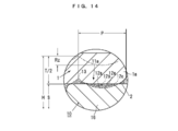
- the cold flow fills the machining groove 12 (FIG. 14).
- a high degree of watertightness that is, non-leakage and further water vapor impermeability
- the sliding resistance during injection of the piston member 10 into the syringe barrel 1 is 12 N or less, which is required.
- the invention according to claim 2 is characterized in that, in the piston member 10 according to claim 1, the maximum height roughness Rz at the time of cutting is formed to be 6 ⁇ m or less. If the maximum height roughness (in other words, the groove depth or 10-point average roughness) Rz of the machining groove 12 is 6 ⁇ m or less (preferably 3 ⁇ m or less), the machining groove 12 is reliably embedded by cold flow. Done.
- the invention described in claim 3 is characterized in that, in the piston member 10 of claim 1, the ridge 13 is formed in a spiral shape.
- the processing groove 12 becomes a spiral groove, and it is common knowledge that the chemical solution 30 flows out through the spiral processing groove 12.
- the cold flow fills the processing groove 12. Realize water tightness. Since the machining groove 12 is spiral, the piston member 10 can be formed by ordinary lathe machining, and rapid and inexpensive production is possible.
- the invention described in claim 4 is characterized in that, in the piston member 10 of claim 1, the ridges 13 are formed in a ring shape.
- the pitch P of the ridges 13 is as very small as 50 ⁇ m, and therefore the thickness of the ridges 13 themselves is very thin, so that the placebo 30 passes through the grain boundaries of the PTFE lump existing on the ridges 13. 13 passes through and leaks.
- the press-fitting allowance T is set to 10 to 150 ⁇ m
- the ridges 13 are crushed and the grain boundaries of the PTFE lump are eliminated as described above. Passing through is also gone. This point can also be applied to the case of the spiral.
- the sliding resistance is 12N or less as described above.
- the invention according to claim 5 is the piston member 10 according to any one of claims 1 to 4, wherein the width D of the sliding contact surface 11a of the piston member 10 is 0.5 mm to 3mm ".
- the width D of the slidable contact surface 11a is 0.5 mm or less, the liquid contact side sliding portion 16 on which the slidable contact surface 11a is formed is weak in strength and may be damaged during handling. If there is, when the syringe barrel 1 is a cycloolefin resin, the surface pressure with respect to the syringe barrel 1 of the press-fitted wetted sliding portion 16 may become too high, and the syringe barrel 1 may be broken.
- the invention according to claim 6 is the piston member 10 according to any one of claims 1 to 4, wherein “the sliding contact surface 11a adjacent to the liquid contact surface of the piston member 10 is In other words, the thickness gradually decreases from the wetted surface 14 side toward the opposite non-wetted surface 14a side ”.
- the invention according to claim 7 is the piston member 10 according to any one of claims 1 to 4, wherein “the sliding contact surface 11a adjacent to the liquid contact surface of the piston member 10 is in contact with the piston member 10. It is thin in a concave arc shape between the liquid surface 14 side and the opposite non-wetted surface 14a side. "
- the invention according to claim 8 is the piston member 10 according to any one of claims 1 to 4, wherein “the sliding contact surface 11a adjacent to the liquid contact surface of the piston member 10 is in contact with the piston member 10. Between the liquid surface 14 side, the non-wetted surface 14a side opposite to the liquid surface 14 side, and the central portion thereof, it is thinned in a concave arc shape.
- the invention according to claim 9 is the piston member 10 according to any one of claims 1 to 4, wherein “the liquid contact of the sliding contact surface 11a adjacent to the liquid contact surface of the piston member 10”.
- the diameter of the surface 14 side is formed thicker than the diameter of the opposite non-wetted surface 14a side ".
- the invention according to claim 10 is the piston member 10 according to any one of claims 1 to 4, wherein at least three of the ridges 13 (in other words, counted from the liquid contact surface 14 side) 3 rounds) has the pitch P, the maximum height roughness Rz, and the press-fitting allowance T of claim 1, and the convex strips 13 after 4 strips (in other words, 4 rounds) are the liquid contact surface 14. It is characterized in that at least one of the pitch P, the maximum height roughness Rz, and the press-fitting allowance T is formed larger than the three ridges 13 on the side.
- the liquid contact surface 14 side raises the contact pressure to the inner peripheral surface 2 of the syringe barrel 1 to increase the reliability against liquid leakage, and is narrowed in a narrowed portion or a concave arc shape. In the portion, the contact pressure with respect to the syringe barrel 1 is weakened, so that the piston rod 5 can be pushed with a smaller force.
- the invention according to claim 11 is the piston member 10 according to any one of claims 1 to 4, in which at least three of the ridges 13 (in other words, counted from the liquid contact surface 14 side) 3 rounds) is ring-shaped, and the convex strips 13 after 4 strips (in other words, 4 rounds) are spiral.
- the watertightness is ensured by the ridges 13 (at least 3 or more and up to 5) formed along the narrow processed grooves 12 on the liquid contact surface 14 side, and the non-wetted surface 14a that does not contribute to ensuring the watertightness.
- the processing groove 12 on the side spiral the processing speed can be greatly improved.
- the invention according to claim 12 is characterized in that in the piston member 10 according to any one of claims 1 to 4, the whole piston member 10 is formed of PTFE. To do. In this case, the PTFE bar 50 may be cut, and the production of the piston member 10 is performed quickly and inexpensively in the same manner as normal machining.
- the invention according to claim 13 is the piston member 10 according to any one of claims 1 to 4, wherein “the piston member 10 is only the outer peripheral surface of the chemical-resistant resin material 61. It is formed by cutting at least the PTFE portion of the composite block 60 covered with the PTFE cylinder material 62 ”. In this case, since the composite block 60 is used, the use of expensive PTFE can be reduced. Further, the sliding of the manufactured piston member 10 is ensured by soft PTFE, and the strength and thermal expansion of the piston member 10 are governed by the chemical-resistant resin material 61.
- the piston member 10 is hardly affected by PTFE exhibiting a large thermal expansion near room temperature, the prefilled syringes A and B incorporating the piston member 10 formed by the composite block 60 are affected by the thermal effect of the use environment. Not receive.
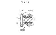
- the invention according to claim 14 is the piston member 10 according to any one of claims 1 to 4, wherein “the cavity 18 is formed inside the sliding contact surface 11a of the piston member 10. It is characterized by. In this case, since the cavity 18 is formed inside the sliding contact surface 11a, the sliding contact portion is thinned and the elasticity is improved. As a result, the touch to the inner peripheral surface 2 of the syringe barrel 1 is further improved. It becomes soft and can push the piston rod 5 with a smaller force.
- the present invention without using a medical plug covering film or silicone oil, and without being limited to a size from a small diameter to a large diameter, it is inexpensive, slidable, and water vapor impermeable. It was possible to provide a piston member for a prefilled syringe or a dual syringe that can sufficiently satisfy water tightness such as non-water leakage.
- Sectional drawing of the prefilled syringe to which this invention is applied is an expanded sectional view of the part shown with the broken-line ellipse of FIG. FIG. 3 is an enlarged front view in which a machining groove is spiral at a portion indicated by a broken line ellipse in FIG. 2.
- channel of FIG. FIG. 3 is an enlarged front view in which a processing groove has a ring shape in a portion indicated by a broken line ellipse in FIG. 2.
- FIG. 3 is an enlarged front view in a case where a processing groove on a liquid contact surface side is a ring shape and a reverse side is a spiral shape in a portion indicated by a broken line ellipse in FIG. 2.
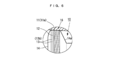
- FIG. 3 is an enlarged front view in a case where a processing groove on the liquid contact surface side is a narrow ring shape in a portion indicated by a broken line ellipse in FIG. 2 and a rough ring shape or a spiral shape on the opposite side.
- FIG. 3 is an enlarged cross-sectional view when a sliding contact surface is formed so as to gradually reduce its diameter from a liquid contact side toward a piston rod side in a portion indicated by a broken line ellipse in FIG. 2.
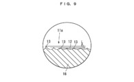
- FIG. 9 is an enlarged cross-sectional view of the portion indicated by a circle in FIG. 8 when the ridge is formed so as to gradually reduce the crest diameter from the liquid contact side toward the piston rod side.
- FIG. 3 is an enlarged cross-sectional view when a sliding contact surface is formed to have a concave arc shape between a liquid contact side and a piston rod side in a portion indicated by a broken line ellipse in FIG. 2.
- FIG. 3 is an enlarged cross-sectional view when a sliding contact surface is formed to form a concave arc shape between a liquid contact side, a piston rod side, and an intermediate portion thereof in a portion indicated by a broken line ellipse in FIG. 2.
- FIG. 3 is an enlarged cross-sectional view when a sliding contact surface is formed to form a concave arc shape between a liquid contact side, a piston rod side, and an intermediate portion thereof in a portion indicated by a broken line ellipse in FIG. 2.
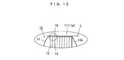
- FIG. 3 is an enlarged cross-sectional view when a liquid contact side of a sliding contact surface is formed thicker than a piston rod side in a portion indicated by a broken line ellipse in FIG. 2.
- FIG. 13 is an enlarged cross-sectional view of a portion indicated by a broken line ellipse in FIG. 12.
- the expanded sectional view at the time of forming a cavity inside the sliding contact surface of the gasket of FIG. The principal part expanded sectional view of the gasket formed using the composite block.
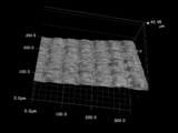
- the figure of the surface roughness measurement result (pitch 50 micrometer) of the gasket of this invention.
- the figure of the surface roughness measurement result (pitch 100 micrometer) of the gasket of this invention.
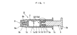
- FIG. 1 is a cross-sectional view of a prefilled syringe A to which the gasket 10a of the present invention is applied
- FIG. 18 is a cross-sectional view of a dual syringe B to which the intermediate piston 10b and the gasket 10a of the present invention are applied.
- the prefilled syringe A includes a gasket 10 a that is a piston member 10, a syringe barrel 1, a piston rod 5 that is attached to the gasket 10 a, and a top cap 8.
- an intermediate piston 10b which is the piston member 10 is further used.
- symbol 30 in FIG. 1 is the chemical
- symbol 31 in FIG. 18 is a powder-form chemical
- 32 is the water for injection which melt
- FIG. 1 will be described.
- common members are denoted by the same reference numerals, and in the description of FIG. 2 and subsequent drawings, the overlapping portions use the description that has already been described, and in order to avoid complication, the description thereof is in principle. Omitted.
- the syringe barrel 1 is a cylindrical container, and a mounting portion 1b on which a syringe needle (not shown) is mounted protrudes from the tip of the barrel main body 1a, and a hook portion 1c is formed at the rear end.
- a syringe needle (not shown) is mounted protrudes from the tip of the barrel main body 1a, and a hook portion 1c is formed at the rear end.
- glass glass, hard resin (for example, cycloolefin resin; hereinafter referred to as COP), soft resin (for example, polypropylene, hereinafter referred to as PP), or the like is used.
- COP cycloolefin resin
- PP polypropylene
- the piston member 10 including the gasket 10a shown in FIG. 1 and the intermediate piston 10b shown in FIGS. 16 and 17 is formed of PTFE as a whole, and the central portion is made of the chemical resistant resin 61 and is at least cut. There are two cases where the part is formed of PTFE.
- the PTFE used in the present invention may be pure PTFE.
- PFA polytetrafluoroethylene-perfluoroalkyl vinyl ether copolymer
- PFA polytetrafluoroethylene-perfluoroalkyl vinyl ether copolymer
- a modified body in which 1 to 15% by mass of a fluororesin such as a propylene copolymer is mixed because elasticity is imparted to the piston member 10.
- a round bar 50 as shown in FIG. 19 is used.
- the above pure PTFE or a modified PTFE, and further, a block (round bar material) formed into a closed cell by a hot isostatic pressing method called a so-called HIP treatment is used.
- PTFE before HIP treatment is made by molding powder PTFE or modified PTFE into a block shape (for example, a cylindrical shape) at high pressure and sintering it, so it is an aggregate of fine PTFE masses. These are open-cell blocks in which fine gaps are continuously connected to the grain boundaries of the PTFE block.
- An example of the hot isostatic pressing method is as follows.
- the above-mentioned open cell type PTFE block or open cell type modified PTFE block (for example, a rod-like body) is put into a heating furnace, and first the inside of the heating furnace is 0.013 to 133 Pa (normally used vacuum is 0.13 to 13.3 Pa).
- the pressure is reduced to a degree of vacuum to eliminate the gas from the pressure molded body.
- heat fusion treatment is carried out at 320 to 400 ° C. (more preferably 350 to 370 ° C.) for several hours to 10 and several hours, and this is cooled to obtain a closed cell type PTFE block.
- the temperature is raised to the above temperature while the pressure is reduced to the above degree of vacuum, and after holding for the above time, the pressure is returned to normal pressure and cooled under pressure to obtain a closed cell PTFE block.
- FIG. 20 shows a composite block 60 in which the outer peripheral surface of a round bar-shaped chemical-resistant resin material 61 is covered with a PTFE cylinder material 62 that is cut.
- the chemical-resistant resin material 61 is, for example, COP or ultra-high molecular polyethylene, and after inserting the chemical-resistant resin material 61 into the heated cylindrical PTFE member 62, these are cooled to shrink the cylindrical PTFE member 62.
- the outer peripheral surface of the chemical resistant resin material 61 is covered. So-called shrink fitting is performed.
- a round bar material of the chemical resistant resin material 61 may be press-fitted into the cylindrical PTFE member 62 and integrated.
- the PTFE member 62 extended by press fitting is integrated by tightening.
- the PTFE member 62 only needs to have a thickness (1 to 2 mm) necessary for cutting. If the diameter of the chemical-resistant resin material 61 is sufficiently large with respect to the thickness of the PTFE member 62, the composite block 60 is not affected by PTFE exhibiting a large thermal expansion near room temperature, and the composite block 60 has a thermal expansion smaller than that of PTFE. Therefore, the dimensional change is sufficiently suppressed in the vicinity of 0 ° C. to around room temperature.
- the PTFE member 62 of the composite block 60 may be the above-mentioned open cell or may be made into a closed cell by performing a HIP process.
- the gasket 10a is formed such that the outer periphery of the liquid contact side sliding portion 16 and the end portion 17 on the mounting side of the piston rod 5 is thick, and the space between the liquid contact side sliding portion 16 and the mounting side end portion 17 is narrow. .
- the end 17 guides the sliding of the gasket 10a so that the piston rod 5 attached to the gasket 10a does not sway, and its maximum outer diameter is substantially equal to or slightly thinner than the inner diameter of the syringe barrel 1.
- the shape of the outer peripheral portion of the end portion 17 is formed in a mountain shape with a cross section parallel to the central axis, and the outer periphery thereof is in sliding contact with the inner periphery of the syringe barrel 1. If it does not interfere with the sliding of the piston rod 5, it can be omitted.
- the liquid contact side sliding portion 16 of the gasket 10 a is a sliding contact portion with the inner peripheral surface 2 of the syringe barrel 1, is adjacent to the liquid contact surface 14 with the chemical solution 30, and extends from the liquid contact surface 14 to the piston rod 5.
- the width D is 0.5 to 3 mm.
- a preferred width D is 1 to 2 mm.
- the width D applies to both the spiral case, the independent ring shape, and variations thereof.
- the processing groove 12 may have a spiral shape or an independent ring shape. These will be described in detail later.
- FIG. 13 is a partially enlarged cross-sectional view of a cut portion, and a ridge 13 having a substantially triangular cross section is formed between the processed grooves 12 cut by the blade.
- Rz the maximum height roughness
- FIG. 25 shows the case where the pitch P of the ridges 13 is 50 ⁇ m, the maximum height roughness Rz is 2.3 ⁇ m (at this time, the arithmetic average roughness Ra is 0.36 ⁇ m), and in the liquid leakage test described later, There was no leakage.
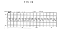
- FIG. 26 shows the case where the pitch P of the ridges 13 is 100 ⁇ m and the maximum height roughness Rz is 6.6 ⁇ m (the arithmetic average roughness Ra is 1.54 ⁇ m at this time). Liquid leakage was observed. Measurement was performed using a surface shape analyzer manufactured by Tokyo Seimitsu Co., Ltd.
- the cutting method is to project PTFE blocks 50 and 60 (bars, preferably round bars) from a lathe chuck by a predetermined amount, and then scrape the end face of the protruding portion into a flat or required predetermined shape, and then to the protruding portion.
- the piston member 10 is the gasket 10a or the intermediate piston 10b
- the outer peripheral surface is cut into a predetermined shape to be described later.
- the intermediate piston 10b when the cutting of the outer shape is finished, the intermediate piston 10b is finished by cutting off at the base of the protruding portion.
- a pilot hole of a female screw hole 15 for screwing the male screw portion 5a of the piston rod 5 is further drilled in the center of the end face of the protruding portion, and then the female screw is engraved into the pilot hole by tapping. Then, the opening edge of the female screw hole 15 is chamfered, and finally cut off at the base of the protruding portion with a predetermined size to finish the gasket 10a.
- the feed width is indicated by pitch P in FIG.
- FIG. 4 shows a modification of this example, in which only the portion adjacent to the wetted surface 14 (for example, 3 to 5 strips (ie, 3 to 5 rounds) in the spiral groove) is cut to 50 ⁇ m or less, and the other portions are more Increase cutting speed by rough cutting.
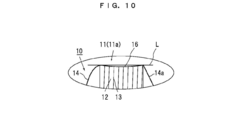
- FIG. 5 to 12 show modified examples of the sliding contact surface 11a of the piston member 10, and FIG. 5 shows a case where ring ridges 13b are formed at equal intervals over the entire sliding contact surface 11a.
- the machining groove 12 is scraped off by 1 pitch P, and then the cutter is retracted and separated from the PTFE round bar 50, the cutter is moved horizontally by 1 pitch P, and the cutter is again PTFE round.
- the processing groove 12 is scraped off by 1 pitch P in contact with the bar 50.
- the ring protrusion 13b is formed on the sliding contact surface 11a.
- FIG. 6 shows the ring ridges 13b at a pitch P of 50 ⁇ m or less by 1 (ie, 1 round) of the ridges 13 on the wetted surface 14 side, and 3-5 (ie, 3-5 laps) for safety. Is formed, and the remaining portion is the spiral ridge 13a.
- FIG. 7 one protrusion 13 on the wetted surface 14 side is formed, and for safety, a ring protrusion 13b is formed by 3 to 5 with a pitch P of 50 ⁇ m or less, and the remaining portion is formed with a pitch of 50 ⁇ m or more.
- a rough ring ridge 13b is formed.
- FIGS. 3 to 7 are examples of creating the ridges 13.
- FIG. 8 to 12 are modified examples of the sliding contact surface 11a, and these are applied to FIGS. 3 to 7.
- L in the drawing is a line parallel to the center line, for easy understanding of the shape of the sliding contact surface 11a.
- the diameter (peak diameter H) of the liquid contact side sliding portion 16 gradually decreases from the liquid contact surface 14 side toward the opposite non-wetted surface 14 a side.
- FIG. 9 is a partially enlarged cross-sectional view of a portion surrounded by a circle in FIG.
- the diameter (crest diameter H) of the liquid contact side sliding portion 16 is reduced in a concave arc shape between the liquid contact surface 14 side and the non-liquid contact surface 14 a side opposite to the liquid contact surface 14 side.
- the same partial diameter (mountain diameter H) is formed in a concave arc shape between the liquid contact surface 14 side, the non-liquid contact surface 14a side, and the central portion thereof.
- the diameter (peak diameter H) of the part adjacent to the wetted surface 14 of the same part is thick, and the non-wetted surface 14a side diameter (peak diameter H) is formed thinner than this.
- the spiral protrusion 13a adjacent to the liquid contact surface 14 needs to have a width of at least three or more, and a width of about five when securing watertightness or water vapor impermeability.
- the number of the ring ridges 13b is theoretically one, but it is preferable that the number is three or more in consideration of safety. 8 to 12, in any case, the portion on the liquid contact surface 14 side formed with a large diameter is in strong contact with the inner peripheral surface 2 of the syringe barrel 1 to ensure water tightness and water vapor impermeability. ing. The figure is shown in FIG. And even the thinly formed portion is in light contact with the inner peripheral surface 2 of the syringe barrel 1 during insertion. By doing in this way, the liquid contact surface 14 side raises the contact pressure to the inner peripheral surface 2 of the syringe barrel 1 to increase the reliability against liquid leakage, and is gradually narrowed in a narrowed portion or a concave arc shape.
- the contact pressure becomes weak, and the piston rod 5 can be pushed with a smaller force.
- the portion formed with a large diameter is the liquid contact surface 14 side.
- the present invention is not limited to this, and any portion of the sliding contact surface 11a can be formed.
- FIG. 14 is an enlarged cross-sectional view of a portion that is in strong contact with the syringe barrel 1 described above.
- FIG. 21 (1000 times) is a reverse photograph of the processing groove 12
- FIG. 22 is a reverse photograph of the processed groove 12 (1000 times).
- 27 is an enlarged photograph of the boundary portion between the liquid contact surface 14 of the piston member 10 and the placebo 30 on the inner peripheral surface 2 of the syringe barrel 1, and shows a state where the placebo 30 is stopped by the ridges 13.
- the horizontal streaks that shine white are the processed grooves 12, and the cold flow from the ridges 13 does not sufficiently fill the processed grooves 12 between the ridges 13.
- the protrusions 13 in the vicinity of the boundary between the liquid contact surface 14 of the piston member 10 and the placebo 30 are crushed to sufficiently fill the machining groove 12.
- FIGS. 21 and 22 in which the ridges 13 are shown in an inverted state the groove bottom 12a of the processed groove 12 cut off by the sharp cutting edge of the cutting tool has a shallow continuous concave arc shape.
- a ridge 13 with a thin ridge line at the tip and a continuous wavy ridge continues.
- the machined grooves 12 and the ridges 13 are somewhat uneven, unlike metal cutting.
- the cutting surface is the highest in high-speed steel and becomes smooth in the order of carbide, polycrystalline diamond, and single crystal diamond. The smoother the cutting surface, the better the water tightness and vapor impermeability.
- the processed grooves 12 and the ridges 13 cut as described above have some irregularities, but PTFE has a high deformability, and when the piston member 10 is inserted into the syringe barrel 1 with a press-fitting margin T, Of course, even in the case of a ring shape, the ridges 13 are strongly crushed by the inner peripheral surface 2 of the syringe barrel 1 and flow into the machining groove 12 side (cold flow), and the pitch P of the ridges 13 is 50 ⁇ m during cutting.
- the maximum height roughness Rz is 6 ⁇ m or less and the press-fitting allowance T is 10 ⁇ m or more in diameter, the processed groove 12 is completely filled in a considerable portion.
- the buried portion is indicated by reference numeral 12a, and the boundary thereof is indicated by reference numeral 12b.
- the entire embedded state of the processed groove 12 is remarkable. As a result, even if the processing groove 12 is a spiral groove, the above-described watertightness and water vapor impermeability are ensured.
- the pitch P of the ridges 13 is 50 ⁇ m or more, it is related to the maximum height roughness Rz, but the processed grooves 12 are not sufficiently filled, and water may leak through the remaining fine gaps.
- the ambient temperature difference is large (for example, when stored in a refrigerator, and then taken out and returned to room temperature before injection)
- the physical properties of PTFE a large dimensional change occurs near room temperature. May cause liquid leakage.
- the range of 3 to 40 ⁇ m has the highest reliability for non-leakage.
- the pitch P of the ridges 13 is 3 ⁇ m or less, it takes too much time for cutting, and the height of the ridges 13 between the machining grooves 12 becomes too low (that is, the maximum height roughness of the machining grooves 12). Rz becomes too shallow) and the elasticity of the ridge 13 becomes too small. Therefore, the pitch P of the ridges 13 is practically preferable to be 3 ⁇ m or more and 40 ⁇ m or less.
- the maximum height roughness Rz of the processed groove 12 at the time of cutting is deeper than 6 ⁇ m, there is a risk that the cold-flowed PTFE cannot fully fill the groove bottom 12a of the processed groove 12 and water leakage occurs.
- the maximum height roughness Rz is preferably 3 ⁇ m or less. From the viewpoint of groove filling by cold flow, the maximum height roughness Rz is preferably shallow.
- the groove bottom 12a in an arc shape.
- the groove pitch P and the maximum height roughness Rz are basically not related to the thickness of the syringe barrel 1 and can be applied to the syringe barrel 1 of any thickness. If the groove pitch P and the maximum height roughness Rz are within the above ranges, high water tightness (non-leakage and water vapor impermeability) can be realized even if the processed groove 12 is a spiral groove.
- the diameter of the liquid contact side sliding portion 16 is increased by a minimum of 10 ⁇ m (5 ⁇ m in radius) and a maximum of 150 ⁇ m (75 ⁇ m in radius) as a press-fit allowance T (see FIG. 24).
- PTFE that has not been subjected to HIP processing has a fine communication gap inside.
- the piston member 10 is inserted into the syringe barrel 1 with the press-fitting allowance T and the ridges 13 are crushed, these fine communication gaps will be clogged during the cold flow described above, Even PTFE that has not been subjected to HIP treatment will not only allow water leakage through the communication gap but also water vapor.
- the relationship between the inner diameter S of the syringe barrel 1 and the outer diameter of the liquid contact side sliding portion 16 of the piston member 10 (press fitting allowance T) is within the above range, and the groove pitch P of the processing groove 12 of the sliding contact surface 11a.
- the width D of the sliding contact surface 11a of the piston member 10 is set to 0.5 to 3 mm. If the width D is smaller than 0.5 mm, the wetted sliding portion 16 may be damaged during handling. If the width D is 3 mm or more, the press-fitting allowance of the piston member 10 to the syringe barrel 1 is 50 ⁇ m.
- the surface pressure of the liquid contact side sliding portion 16 against the syringe barrel 1 becomes too high, and if steam sterilization is performed at room temperature or at 121 ° C. for 20 minutes, There is a possibility that the piston member 10 expands beyond the syringe barrel 1 and the syringe barrel 1 breaks. Practically, it is 1 to 2 mm.
- the intermediate piston 10b has liquid contact side sliding portions 16 formed at both ends, and the space between both liquid contact side sliding portions 16 is formed narrow.
- the slidable contact surface 11a of the both liquid contact side sliding portions 16 is formed exactly the same as the slidable contact surface 11a of the gasket 10a.
- the syringe barrel 1 has a needle mounting portion 1b at the front end, a finger hook portion 1c at the rear end, and a cylindrical chemical solution filling portion 4c formed therebetween, and is formed of a cyclic polyolefin in this embodiment.
- the shape of the syringe barrel 1 is not limited to that illustrated, and the syringe barrel 1 can be made of polypropylene, glass, or the like.
- the piston rod 5 is a rod-shaped member provided with a male screw portion 5a at the front end and a finger contact portion 5b at the rear end. On the outer peripheral surface of the male screw portion 5a of the piston rod 5, a male screw that is screwed into the female screw hole 15 of the gasket 10a described above is formed.
- the material of the piston rod 5 is made of resin such as cyclic polyolefin, polycarbonate, and polypropylene.
- the top cap 8 is attached to the needle mounting portion 1b of the syringe barrel 1 so that the chemical solution 30 filled in the syringe barrel 1 does not leak, and the chemical solution 30 is not contaminated by various germs floating in the air. It is the sealing member for doing.
- the top cap 8 is composed of a truncated cone-shaped cap body 8a and a fitting protrusion 8c extending in the opening direction from the top surface of the cap body 8a and having a recess 8b into which the needle mounting portion 1b is fitted. ing.
- the top cap 8 is formed of an elastomer. Elastomers include both “thermosetting elastomers” such as vulcanized rubber and thermosetting resin elastomers and “thermoplastic elastomers”.
- Such a member is assembled, and the drug solution 30 is filled in the closed space of the syringe barrel 1 and the gasket 10a to constitute a prefilled syringe A as shown in FIG.
- the top cap 8 is removed, and the prefilled syringe A can be used simply by mounting a predetermined needle on the needle mounting portion 1b of the syringe barrel 1.
- the movement of the piston rod 5 is extremely smooth, including the initial movement, and does not exceed 12 N, as can be seen from the sliding resistance test described later.
- the gasket 10a is leaked on the sliding contact surface 11a with the inner peripheral surface 2 of the syringe barrel 1 over a long period of time due to its excellent water repellency. Neither liquid nor permeation of the water vapor occurs.
- the gasket 10a in FIG. 20 uses the above-described composite block 60 in which only the outer peripheral surface of the chemical-resistant resin material 61 is covered with the PTFE member 62, and the PTFE portion is already described according to the inner diameter S of the syringe barrel 1. A predetermined cutting process is performed to obtain a gasket 10a having a predetermined shape. This also applies to the intermediate piston 10b.
- the resin material 61 is exposed on the liquid contact surface 14, but the resin material 61 is excellent in chemical resistance such as COP and ultra-high molecular weight polyethylene, so that it comes into contact. It does not adversely affect the chemical solution 30 that is present. Since the slidable contact surface 11a is formed of PTFE, no liquid leakage occurs and excellent slidability is exhibited. If a resin harder than PTFE is selected as the chemical-resistant resin material 61, the outer PTFE is reinforced from the inside, and the chemical-resistant resin material 61 usually has a temperature range from around 0 ° C. to around room temperature. Since the coefficient of thermal expansion is smaller than that of PTFE, the piston member 10 is less affected by changes in the outside air temperature, and the dimensional change with respect to temperature is superior to that of PTFE alone.
- chemical resistance such as COP and ultra-high molecular weight polyethylene
- FIG. 17 shows a further modification of the gasket 10a.
- the gasket 10a is composed of a main body portion 20 and a liquid contact side sliding contact ring 23 fitted on the liquid contact side outer peripheral surface 21 of the main body portion 20. Only the sliding contact ring 23 is made of PTFE or closed cell PTFE. The liquid contact side sliding contact ring 23 is formed by cutting as described above. Then, the liquid contact side sliding contact ring 23 is fitted into the mold, and the above-described chemical liquid resistant resin that does not adversely affect the chemical liquid 30 is injected, and the liquid contact side sliding portion 27 of the main body portion 26 is in contact with the liquid contact side.
- the gasket 10a has a shape in which the sliding contact cap 28 is fitted.
- the intermediate piston 10b can be formed in which the liquid contact side sliding contact ring 23 is fitted to the liquid contact side outer peripheral surface 21 provided at both ends thereof. it can.
- the liquid contact side sliding contact ring 23 may be fitted into the body portion 20 which has been molded in advance. Note that the main body portion 26 may be cut and fitted into the liquid contact side sliding portion 27.
- FIG. 18 is an example of a dual syringe B that uses the intermediate piston 10b, and is an example in which the syringe barrel 1 is provided with a bypass 1d.
- the intermediate piston 10b is accommodated in the syringe barrel 1, and a piston rod 5 having a gasket 10a attached to the flange 1c side of the syringe barrel 1 is inserted.
- the intermediate piston 10b is disposed on the flange 1c side beyond the opening 1e portion on the flange 1c side of the bypass 1d, and the sealed space between the intermediate piston 10b and the gasket 10a is filled with water 32 for injection.
- medical agent 31 is filled in the space comprised by the needle mounting part 1b and the intermediate piston 10b.
- the top cap 8 When in use, the top cap 8 can be removed and the needle can be used immediately if it is mounted on the needle mounting portion 1b.
- the intermediate piston 10b moves forward through the filled water 32 for injection, and when the rear end of the intermediate piston 10b exceeds the opening 1e portion on the flange 1c side of the bypass 1d, the water 32 for injection is The drug passes through the bypass 1d and flows into the sealed space filled with the drug 31 from the opening portion 1f on the distal end side, so that the drug 31 is melted and injected.
- the sliding resistance is almost the same as that of the prefilled syringe A of FIG.
- the present invention will be described in more detail with reference to Examples and Comparative Examples.
- the syringe barrel is filled with colored pure water (placebo), and using the PTFE gasket of the present invention, the liquid sealing property (liquid leakage), the water vapor permeability test, and the sliding property (piston) Rod pressure) was tested.
- Each test has 10 tests.
- Liquid sealability (liquid leakage) test The interface part between the sliding surface of the gasket and the inner peripheral surface of the syringe barrel was magnified 100 times, and the presence or absence of leakage to the sliding part of the placebo was observed. .
- the pitch P of the ridges was 50 ⁇ m or less and the maximum height roughness Rz was 6 ⁇ m or less
- liquid leakage did not occur at room temperature in any of PP, COP and glass syringe barrels.
- any syringe barrel of any inner diameter liquid leakage was observed when the pitch P of the ridges was 80 ⁇ m and 100 ⁇ m.
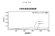
- the precision balance used for the measurement can measure up to 1 / 10,000 g. Even after 1,500 hours, the weight loss of the syringe barrel using the gasket of the present invention was almost zero, and the fluctuation range was within the error range of the precision balance. On the other hand, a conventional syringe barrel using a butyl rubber gasket showed a weight loss of 0.005 g.
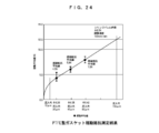
- the average value of these is connected by a straight line, and the horizontal line drawn from the place where the sliding average value (N) is 12N and the intersection point are obtained, and a press-fitting allowance of 150 ⁇ m is obtained. That is, even if the press-fitting allowance is increased to 150 ⁇ m in diameter with respect to the syringe barrel 1, it can be said that the slidability is not impaired. However, in the case of the COP syringe barrel, if the press-fitting allowance is 150 ⁇ m or more in diameter and the width D of the sliding contact surface 11a exceeds 3 mm, the COP syringe barrel may be cracked.
- the upper limit of the press-fitting allowance is 150 ⁇ m.
- the lower limit is 10 ⁇ m in consideration of the relationship between PTFE cold flow, groove depth, and pitch.
- the press allowance was 10 ⁇ m or less, the processed groove could not be filled and water leakage occurred.
Abstract
Description
PTFEブロックを切削加工して形成され、シリンジバレル1に圧入されて摺動状態で用いられるピストン部材10に於いて、
シリンジバレル1の内周面2に摺接するピストン部材10の摺接面11の内、少なくとも薬液30との接液面14に隣接する摺接面11aの全周に亙って周方向の凸条13が形成され、
切削加工時の凸条13のピッチPが50μm以下、シリンジバレル1に対するピストン部材10の圧入代Tが10~150μmであることを特徴とするピストン部材10である。 The invention described in
In the
Of the
The
図1のようにシリンジバレルに着色した純水(偽薬)を充填し、本発明のPTFE製ガスケットを用いて下記の方法で液体密封性(液漏れ)、水蒸気透過性試験及び摺動性(ピストンロッドの加圧力)を試験した。いずれの試験も試験本数はそれぞれ10本である。
本発明のガスケットの条件
シリンジバレル(材質:COP、ガラス)の内径(単位:mm)
=6.34 12.45 20.20
接液側摺動部の直径(山径H)(圧入代Tは40μm)(単位:mm)
=6.38 12.49 20.24
凸条のピッチP(μm)
=3 5 10 20 30 40 50 80 100
加工溝の最大高さ粗さ:Rz(単位:μm)
=2.3 6.0 6.6 10
摺接面の幅(単位:mm)
=0.5 1.0 1.5 2.5 3.5 Hereinafter, the present invention will be described in more detail with reference to Examples and Comparative Examples.
As shown in FIG. 1, the syringe barrel is filled with colored pure water (placebo), and using the PTFE gasket of the present invention, the liquid sealing property (liquid leakage), the water vapor permeability test, and the sliding property (piston) Rod pressure) was tested. Each test has 10 tests.
Condition of gasket of the present invention Inner diameter (unit: mm) of syringe barrel (material: COP, glass)
= 6.34 12.45 20.20
Diameter (mountain diameter H) of the sliding part on the wetted side (press fit allowance T is 40 μm) (unit: mm)
= 6.38 12.49 20.24
Ridge pitch P (μm)
= 3 5 10 20 30 40 50 80 100
Maximum height of processed groove roughness: Rz (unit: μm)
= 2.3 6.0 6.6 10
Width of sliding surface (unit: mm)
= 0.5 1.0 1.5 2.5 3.5
ガスケットの摺接面とシリンジバレルの内周面との界面部分を100倍に拡大して観察し、偽薬の摺動部分への漏れの有無を観察した。凸条のピッチPが50μm以下、最大高さ粗さRzが6μm以下のものはPP製、COP製、ガラス製シリンジバレルのいずれの場合でも室温に於いて液漏れを生じなかった。
いずれの内径のシリンジバレルに於いても、凸条のピッチPが80μm、100μmのものには液漏れが観察された。凸条のピッチPが50μmのガスケットでは上記のように室温では問題がないが、偽薬を充填したプレフィルドシリンジを5℃の冷蔵庫に一晩保管した後、室温に戻すと若干の液漏れが観察されたものがあった。凸条のピッチPが40μm以下のガスケットでは液漏れはなかった。また、最大高さ粗さRz(溝深さ)が6.6μm、10μmのものには液漏れが観察されたが、6μm以下では液漏れはなかった。上限は溝ピッチが50μm、最大高さ粗さRz(溝深さ)は6μmであり、安全をみれば、溝ピッチは40μm以下、最大高さ粗さRz(溝深さ)は3μmである。 (1) Liquid sealability (liquid leakage) test The interface part between the sliding surface of the gasket and the inner peripheral surface of the syringe barrel was magnified 100 times, and the presence or absence of leakage to the sliding part of the placebo was observed. . In the cases where the pitch P of the ridges was 50 μm or less and the maximum height roughness Rz was 6 μm or less, liquid leakage did not occur at room temperature in any of PP, COP and glass syringe barrels.
In any syringe barrel of any inner diameter, liquid leakage was observed when the pitch P of the ridges was 80 μm and 100 μm. As described above, there is no problem at room temperature with a gasket having a convex pitch P of 50 μm, but after storing the prefilled syringe filled with placebo in a refrigerator at 5 ° C. overnight, a slight liquid leakage is observed when it is returned to room temperature. There was something. There was no liquid leakage in the gasket having a pitch P of 40 μm or less. Further, liquid leakage was observed when the maximum height roughness Rz (groove depth) was 6.6 μm and 10 μm, but there was no liquid leakage below 6 μm. The upper limit is 50 μm for the groove pitch and 6 μm for the maximum height roughness Rz (groove depth). For safety reasons, the groove pitch is 40 μm or less and the maximum height roughness Rz (groove depth) is 3 μm.
ガラス製シリンジバレル(内径6.34mm 全容量2ミリリットル)に着色した純水1ミリリットルを充填し、液漏れのない形状に製作した上記PTFEガスケット(摺接面11aの幅D=2.5mm 直径(山径H)=6.38mm 圧入代=40μm)を装着し、シリンジバレルの先端にはブチルゴム製トップキャップを装着して経時重量変化を測定した。比較例として同シリンジバレルに常用されているブチルゴム製ガスケットを使用した。
測定に使用した精密天秤(島津製作所製)は1/10,000gまで測定可能である。
1,500時間経過しても、本発明のガスケットを使用したシリンジバレルの減量はほぼ0であり、変動幅は精密天秤の誤差範囲内であった。一方、ブチルゴム製ガスケットを使用した従来のシリンジバレルは0.005gの減量が認められた。 (2) Water vapor permeability test (Figure 23)
The above PTFE gasket (sliding
The precision balance (manufactured by Shimadzu Corporation) used for the measurement can measure up to 1 / 10,000 g.
Even after 1,500 hours, the weight loss of the syringe barrel using the gasket of the present invention was almost zero, and the fluctuation range was within the error range of the precision balance. On the other hand, a conventional syringe barrel using a butyl rubber gasket showed a weight loss of 0.005 g.
本発明のガスケットの条件
接液側摺動部の直径(山径H)=6.36 6.38 6.40(単位:mm)
摺接面の幅=2.3mm
シリンジバレル(COP、ガラス)の内径=6.34mm
試験速度=100mm/分
平均摺動抵抗は6.36mmで4.2N、6.38mmで5.9N、6.40mmで7.4Nといずれも要求される12N以下である。ガスケット10aにPTFEを使用する場合、これらの平均値を直線で結び、摺動平均値(N)が12Nのところから引いた横線と交点を求めると、圧入代150μmが求められる。即ち、シリンジバレル1に対して圧入代を直径で150μmまで大きくしても摺動性を損なうことはないと言える。ただし、COPシリンジバレルの場合、圧入代を直径で150μm以上とし、摺接面11aの幅Dが3mmを越えるとCOPシリンジバレルに割れを生じることがある。従って、圧入代の上限は150μmと言うことになる。
下限はPTFEのコールドフローと溝深さ、ピッチの関係から考慮して10μmである。圧入代が10μm以下であると加工溝を埋めきれず漏水が発生した。 (3) Measurement of sliding resistance value (FIG. 24)
Condition of gasket of the present invention Diameter of wetted side sliding part (crest diameter H) = 6.36 6.38 6.40 (unit: mm)
Sliding surface width = 2.3 mm
Inner diameter of syringe barrel (COP, glass) = 6.34 mm
Test speed = 100 mm / min The average sliding resistance is 4.2 N at 6.36 mm, 5.9 N at 6.38 mm, and 7.4 N at 6.40 mm, all of which are less than the required 12 N. When PTFE is used for the
The lower limit is 10 μm in consideration of the relationship between PTFE cold flow, groove depth, and pitch. When the press allowance was 10 μm or less, the processed groove could not be filled and water leakage occurred.
Claims (14)
- PTFEブロックを切削加工して形成され、シリンジバレルに圧入されて摺動状態で用いられるピストン部材に於いて、
シリンジバレルの内周面に摺接するピストン部材の摺接面の内、少なくとも薬液との接液面に隣接する摺接面の全周に亙って周方向の凸条が形成され、
切削加工時の凸条のピッチが50μm以下、シリンジバレルに対するピストン部材の圧入代が10~150μmであることを特徴とするピストン部材。 In a piston member formed by cutting a PTFE block, press-fitted into a syringe barrel, and used in a sliding state,
Of the slidable contact surface of the piston member slidably in contact with the inner peripheral surface of the syringe barrel, at least a circumferential ridge is formed over the entire periphery of the slidable contact surface adjacent to the liquid contact surface with the chemical solution,
A piston member characterized in that the pitch of the ridges during cutting is 50 μm or less, and the press-fitting allowance of the piston member to the syringe barrel is 10 to 150 μm. - 切削加工時の最大高さ粗さが6μm以下に形成されていることを特徴とする請求項1に記載のピストン部材。 2. The piston member according to claim 1, wherein the maximum height roughness at the time of cutting is 6 μm or less.
- 凸条が螺旋状に形成されていることを特徴とする請求項1に記載のピストン部材。 The piston member according to claim 1, wherein the protrusion is formed in a spiral shape.
- 凸条がリング状に形成されていることを特徴とする請求項1に記載のピストン部材。 The piston member according to claim 1, wherein the protrusion is formed in a ring shape.
- ピストン部材の接液面に隣接する摺接面の幅が、0.5mm~3mmであることを特徴とする請求項1~4のいずれかに記載のピストン部材。 The piston member according to any one of claims 1 to 4, wherein the width of the sliding contact surface adjacent to the liquid contact surface of the piston member is 0.5 mm to 3 mm.
- ピストン部材の接液面に隣接する摺接面が、接液面側から反対側の非接液面側に向けて次第に細くなっていることを特徴とする請求項1~4のいずれかに記載のピストン部材。 5. The sliding contact surface adjacent to the liquid contact surface of the piston member is gradually narrowed from the liquid contact surface side toward the opposite non-wetted surface side. Piston member.
- ピストン部材の接液面に隣接する摺接面が、接液面側と反対側の非接液面側との間で凹弧状に細くなっていることを特徴とする請求項1~4のいずれかに記載のピストン部材。 The sliding contact surface adjacent to the liquid contact surface of the piston member is narrowed in a concave arc shape between the liquid contact surface side and the non-wetted surface side opposite to the liquid contact surface side. A piston member according to any one of the above.
- ピストン部材の接液面に隣接する摺接面が、接液面側、反対側の非接液面側及びその中央部分の間で凹弧状に細くなっていることを特徴とする請求項1~4のいずれかに記載のピストン部材。 The sliding contact surface adjacent to the liquid contact surface of the piston member is narrowed in a concave arc shape between the liquid contact surface side, the opposite non-wetted surface side and the central portion thereof. The piston member according to any one of 4.
- ピストン部材の接液面に隣接する摺接面の接液面側の直径が、反対側の非接液面側の直径より太く形成されていることを特徴とする請求項1~4のいずれかに記載のピストン部材。 5. The diameter of the wetted surface side of the sliding contact surface adjacent to the wetted surface of the piston member is formed to be larger than the diameter of the opposite non-wetted surface side. The piston member according to 1.
- 接液面側から数えて凸条の少なくとも3条が請求項1に記載のピッチ、最大高さ粗さ及び圧入代を有し、4条以降の凸条が前記接液面側の3条の凸条よりピッチ、最大高さ粗さ及び圧入代の少なくとも1つが大きく形成されていることを特徴とする請求項1~4のいずれかに記載のピストン部材。 At least three of the ridges counted from the wetted surface side have the pitch, the maximum height roughness, and the press-fitting allowance according to claim 1, and the four or more ridges are the three strips on the wetted side. The piston member according to any one of claims 1 to 4, wherein at least one of a pitch, a maximum height roughness, and a press-fitting allowance is formed larger than the ridges.
- 請求項1~4のいずれかに記載のピストン部材に於いて、
接液面側から数えて凸条の少なくとも3条がリング状であり、4条以降の凸条が螺旋状であることを特徴とするピストン部材。 The piston member according to any one of claims 1 to 4,
A piston member characterized in that at least three of the ridges counted from the wetted surface side are ring-shaped, and the ridges after the fourth are spiral. - 請求項1~4のいずれかに記載のピストン部材に於いて、
ピストン部材の全体がPTFEで形成されていることを特徴とするピストン部材。 The piston member according to any one of claims 1 to 4,
A piston member characterized in that the whole piston member is formed of PTFE. - 請求項1~4のいずれかに記載のピストン部材に於いて、
ピストン部材が、耐薬液性樹脂材の外周面のみにPTFE筒材を被覆した複合ブロックの少なくともPTFE部分を切削加工して形成されていることを特徴とするピストン部材。 The piston member according to any one of claims 1 to 4,
A piston member, wherein the piston member is formed by cutting at least a PTFE portion of a composite block in which only an outer peripheral surface of a chemical-resistant resin material is covered with a PTFE cylinder material. - 請求項1~4のいずれかに記載の記載のピストン部材に於いて、
ピストン部材の摺接面の内側に空洞が形成されていることを特徴とするピストン部材。 The piston member according to any one of claims 1 to 4,
A piston member, wherein a cavity is formed inside a sliding contact surface of the piston member.
Priority Applications (6)
| Application Number | Priority Date | Filing Date | Title |
|---|---|---|---|
| JP2013528161A JP5406416B1 (en) | 2013-03-04 | 2013-03-04 | Piston member for syringe |
| PCT/JP2013/001314 WO2014136138A1 (en) | 2013-03-04 | 2013-03-04 | Piston member for syringe |
| US14/406,436 US20150148751A1 (en) | 2013-03-04 | 2013-03-04 | Piston member for syringe |
| EP13876947.6A EP2848273A4 (en) | 2013-03-04 | 2013-03-04 | Piston member for syringe |
| CN201380039839.XA CN104519932A (en) | 2013-03-04 | 2013-03-04 | Piston member for syringe |
| IN2272MUN2014 IN2014MN02272A (en) | 2013-03-04 | 2014-11-11 |
Applications Claiming Priority (1)
| Application Number | Priority Date | Filing Date | Title |
|---|---|---|---|
| PCT/JP2013/001314 WO2014136138A1 (en) | 2013-03-04 | 2013-03-04 | Piston member for syringe |
Publications (1)
| Publication Number | Publication Date |
|---|---|
| WO2014136138A1 true WO2014136138A1 (en) | 2014-09-12 |
Family
ID=50202614
Family Applications (1)
| Application Number | Title | Priority Date | Filing Date |
|---|---|---|---|
| PCT/JP2013/001314 WO2014136138A1 (en) | 2013-03-04 | 2013-03-04 | Piston member for syringe |
Country Status (6)
| Country | Link |
|---|---|
| US (1) | US20150148751A1 (en) |
| EP (1) | EP2848273A4 (en) |
| JP (1) | JP5406416B1 (en) |
| CN (1) | CN104519932A (en) |
| IN (1) | IN2014MN02272A (en) |
| WO (1) | WO2014136138A1 (en) |
Cited By (6)
| Publication number | Priority date | Publication date | Assignee | Title |
|---|---|---|---|---|
| JP2016151328A (en) * | 2015-02-18 | 2016-08-22 | 住友ゴム工業株式会社 | Pre-filled syringe, gasket applied to pre-filled syringe and its process of manufacture |
| JP2018102819A (en) * | 2016-12-28 | 2018-07-05 | 住友ゴム工業株式会社 | Medical syringe |
| EP2926851B1 (en) | 2014-03-31 | 2019-07-10 | Sumitomo Rubber Industries, Ltd. | Gasket for prefilled syringe, and production method therefor |
| JP2020120919A (en) * | 2019-01-30 | 2020-08-13 | 住友ゴム工業株式会社 | Gasket for syringe |
| US11071830B2 (en) | 2016-03-29 | 2021-07-27 | Coki Engineering Inc. | High-slidability syringe |
| WO2021255873A1 (en) * | 2020-06-17 | 2021-12-23 | 有限会社コーキ・エンジニアリング | Gasket and syringe using said gasket |
Families Citing this family (20)
| Publication number | Priority date | Publication date | Assignee | Title |
|---|---|---|---|---|
| US9333288B2 (en) * | 2011-09-30 | 2016-05-10 | Becton Dickinson France, S.A.S. | Attachable plunger rod and associated packaging |
| US10561795B2 (en) | 2013-10-07 | 2020-02-18 | Sio2 Medical Products, Inc. | Convertible plungers, film coated plungers and related syringe assemblies |
| CA2960135C (en) | 2014-09-10 | 2023-09-19 | Sio2 Medical Products, Inc. | Three-position plungers, film coated plungers and related syringe assemblies |
| WO2016056038A1 (en) | 2014-10-07 | 2016-04-14 | 有限会社コーキ・エンジニアリング | Slidable medical silicone rubber, gasket using said rubber, and prefilled syringe using said gasket |
| ES2846783T3 (en) | 2015-03-10 | 2021-07-29 | Regeneron Pharma | Aseptic drilling system |
| CN104759003A (en) * | 2015-04-21 | 2015-07-08 | 上海康德莱企业发展集团医疗器械有限公司 | Safety injector |
| CN108025143B (en) | 2015-07-14 | 2021-08-24 | Sio2医药产品公司 | Convertible plunger and method for assembling same in a medical barrel |
| EP3334483B1 (en) * | 2015-08-13 | 2020-05-06 | SHL Medical AG | A stopper for a medicament container |
| US10471211B2 (en) * | 2016-01-15 | 2019-11-12 | W. L. Gore & Associates, Inc. | Medical delivery device with laminated stopper |
| JP6883253B2 (en) | 2016-03-30 | 2021-06-09 | 住友ゴム工業株式会社 | Gasket manufacturing method |
| US10918800B2 (en) | 2016-05-31 | 2021-02-16 | Sio2 Medical Products, Inc. | Convertible plungers and methods for assembling the same in a medical barrel |
| USD870278S1 (en) | 2017-01-13 | 2019-12-17 | Sio2 Medical Products, Inc. | Syringe plunger assembly |
| US10493207B2 (en) * | 2017-02-27 | 2019-12-03 | W. L. Gore & Associates, Inc. | Medical delivery devices having low lubricant syringe barrels |
| CN110234439B (en) * | 2017-03-13 | 2021-03-12 | 纳美仕有限公司 | Prefilled syringe and method for storing resin composition |
| BR112019020705A2 (en) | 2017-05-05 | 2020-05-12 | Regeneron Pharmaceuticals, Inc. | AUTOINJECTOR |
| JP6300137B1 (en) * | 2017-08-29 | 2018-03-28 | 有限会社コーキ・エンジニアリング | Gasket and syringe provided with the same |
| CN109283653A (en) * | 2018-11-24 | 2019-01-29 | 中国科学院长春光学精密机械与物理研究所 | Adhesive dispenser is given for space camera reflecting mirror |
| USD1007676S1 (en) | 2021-11-16 | 2023-12-12 | Regeneron Pharmaceuticals, Inc. | Wearable autoinjector |
| CN114028653B (en) * | 2021-12-01 | 2023-06-02 | 李伟 | Split type syringe and protective needle |
| CN117232726B (en) * | 2023-11-14 | 2024-02-13 | 常州市华伟医疗用品有限公司 | A leakproofness batch detection system for syringe piston |
Citations (3)
| Publication number | Priority date | Publication date | Assignee | Title |
|---|---|---|---|---|
| JP2000342688A (en) * | 1999-06-01 | 2000-12-12 | Material Eng Tech Lab Inc | Syringe |
| JP2002000726A (en) * | 2000-06-21 | 2002-01-08 | Hori Glass Kk | Syringe |
| JP2006181027A (en) | 2004-12-27 | 2006-07-13 | Daikyo Seiko Ltd | Piston for syringe |
Family Cites Families (7)
| Publication number | Priority date | Publication date | Assignee | Title |
|---|---|---|---|---|
| US2160654A (en) * | 1932-09-06 | 1939-05-30 | Claude J Doran | Piston ring |
| US4820278A (en) * | 1988-01-13 | 1989-04-11 | The Boeing Company | Non-contaminating renewable syringe |
| US6139861A (en) * | 1999-01-14 | 2000-10-31 | Friedman; Mark | Intraoral topical anti-inflammatory treatment for relief of migraine, tension-type headache, post-traumatic headache facial pain, and cervical-muscle spasm |
| JP4287561B2 (en) * | 1999-12-01 | 2009-07-01 | 本田技研工業株式会社 | Manufacturing method of sliding contact surface member |
| DE10122959A1 (en) * | 2001-05-11 | 2002-11-21 | West Pharm Serv Drug Res Ltd | Method for producing a piston for a pharmaceutical syringe or a similar item includes a step in which surplus of the inert foil cap on the piston body is separated in a punching unit |
| US7891528B2 (en) * | 2006-07-03 | 2011-02-22 | Nordson Corporation | Dispenser and piston for dispensing a liquid material |
| EP2461912B1 (en) * | 2009-08-04 | 2016-08-17 | 3M Innovative Properties Company | Dispensing device with pressure release |
-
2013
- 2013-03-04 EP EP13876947.6A patent/EP2848273A4/en not_active Withdrawn
- 2013-03-04 CN CN201380039839.XA patent/CN104519932A/en active Pending
- 2013-03-04 JP JP2013528161A patent/JP5406416B1/en active Active
- 2013-03-04 US US14/406,436 patent/US20150148751A1/en not_active Abandoned
- 2013-03-04 WO PCT/JP2013/001314 patent/WO2014136138A1/en active Application Filing
-
2014
- 2014-11-11 IN IN2272MUN2014 patent/IN2014MN02272A/en unknown
Patent Citations (3)
| Publication number | Priority date | Publication date | Assignee | Title |
|---|---|---|---|---|
| JP2000342688A (en) * | 1999-06-01 | 2000-12-12 | Material Eng Tech Lab Inc | Syringe |
| JP2002000726A (en) * | 2000-06-21 | 2002-01-08 | Hori Glass Kk | Syringe |
| JP2006181027A (en) | 2004-12-27 | 2006-07-13 | Daikyo Seiko Ltd | Piston for syringe |
Non-Patent Citations (1)
| Title |
|---|
| See also references of EP2848273A4 * |
Cited By (10)
| Publication number | Priority date | Publication date | Assignee | Title |
|---|---|---|---|---|
| EP2926851B1 (en) | 2014-03-31 | 2019-07-10 | Sumitomo Rubber Industries, Ltd. | Gasket for prefilled syringe, and production method therefor |
| JP2016151328A (en) * | 2015-02-18 | 2016-08-22 | 住友ゴム工業株式会社 | Pre-filled syringe, gasket applied to pre-filled syringe and its process of manufacture |
| CN105879163A (en) * | 2015-02-18 | 2016-08-24 | 住友橡胶工业株式会社 | Prefilled syringe, seal gasket for use in prefilled syringe, and production method thereof |
| CN105879163B (en) * | 2015-02-18 | 2020-12-25 | 住友橡胶工业株式会社 | Prefilled syringe, sealing gasket suitable for prefilled syringe and manufacturing method thereof |
| US11071830B2 (en) | 2016-03-29 | 2021-07-27 | Coki Engineering Inc. | High-slidability syringe |
| JP2018102819A (en) * | 2016-12-28 | 2018-07-05 | 住友ゴム工業株式会社 | Medical syringe |
| JP2020120919A (en) * | 2019-01-30 | 2020-08-13 | 住友ゴム工業株式会社 | Gasket for syringe |
| JP7247608B2 (en) | 2019-01-30 | 2023-03-29 | 住友ゴム工業株式会社 | gasket for syringe |
| WO2021255873A1 (en) * | 2020-06-17 | 2021-12-23 | 有限会社コーキ・エンジニアリング | Gasket and syringe using said gasket |
| JP7012936B1 (en) * | 2020-06-17 | 2022-02-15 | 有限会社コーキ・エンジニアリング | Gasket and syringe using the gasket |
Also Published As
| Publication number | Publication date |
|---|---|
| EP2848273A4 (en) | 2015-04-22 |
| JPWO2014136138A1 (en) | 2017-02-09 |
| CN104519932A (en) | 2015-04-15 |
| US20150148751A1 (en) | 2015-05-28 |
| JP5406416B1 (en) | 2014-02-05 |
| IN2014MN02272A (en) | 2015-08-07 |
| EP2848273A1 (en) | 2015-03-18 |
Similar Documents
| Publication | Publication Date | Title |
|---|---|---|
| JP5406416B1 (en) | Piston member for syringe | |
| EP3231468B1 (en) | Gasket, and medical syringe | |
| JP5977462B1 (en) | Gasket using medical silicone rubber having slidability, syringe using the gasket, and method for producing the same | |
| EP2103320A1 (en) | Piston for syringe | |
| JP6006905B1 (en) | High sliding syringe | |
| EP3120886A1 (en) | Medical syringe, gasket for use in the syringe, and gasket production method | |
| KR102397677B1 (en) | Gasket and syringe having same | |
| CN107185082B (en) | Laminated gasket, medical syringe and method of use thereof | |
| US20230133890A1 (en) | Living hinge seal for silicone-free syringe barrel | |
| WO2017175256A1 (en) | Method for manufacturing bleed type sliding contact ring, and gasket and syringe using sliding contact ring | |
| JP7012936B1 (en) | Gasket and syringe using the gasket | |
| JP2892617B2 (en) | Syringe stopper | |
| JPH09206377A (en) | Slide plug for injector | |
| WO2014155607A1 (en) | Syringe | |
| JP6589406B2 (en) | Prefilled syringe |
Legal Events
| Date | Code | Title | Description |
|---|---|---|---|
| ENP | Entry into the national phase |
Ref document number: 2013528161 Country of ref document: JP Kind code of ref document: A |
|
| 121 | Ep: the epo has been informed by wipo that ep was designated in this application |
Ref document number: 13876947 Country of ref document: EP Kind code of ref document: A1 |
|
| REEP | Request for entry into the european phase |
Ref document number: 2013876947 Country of ref document: EP |
|
| WWE | Wipo information: entry into national phase |
Ref document number: 14406436 Country of ref document: US Ref document number: 2013876947 Country of ref document: EP |
|
| NENP | Non-entry into the national phase |
Ref country code: DE |