WO2014132501A1 - Neutron capture therapy system - Google Patents
Neutron capture therapy system Download PDFInfo
- Publication number
- WO2014132501A1 WO2014132501A1 PCT/JP2013/081511 JP2013081511W WO2014132501A1 WO 2014132501 A1 WO2014132501 A1 WO 2014132501A1 JP 2013081511 W JP2013081511 W JP 2013081511W WO 2014132501 A1 WO2014132501 A1 WO 2014132501A1
- Authority
- WO
- WIPO (PCT)
- Prior art keywords
- irradiation
- neutron
- room
- therapy system
- capture therapy
- Prior art date
Links
Images


Classifications
-
- A—HUMAN NECESSITIES
- A61—MEDICAL OR VETERINARY SCIENCE; HYGIENE
- A61N—ELECTROTHERAPY; MAGNETOTHERAPY; RADIATION THERAPY; ULTRASOUND THERAPY
- A61N5/00—Radiation therapy
- A61N5/10—X-ray therapy; Gamma-ray therapy; Particle-irradiation therapy
- A61N5/1077—Beam delivery systems
- A61N5/1079—Sharing a beam by multiple treatment stations
-
- A—HUMAN NECESSITIES
- A61—MEDICAL OR VETERINARY SCIENCE; HYGIENE
- A61N—ELECTROTHERAPY; MAGNETOTHERAPY; RADIATION THERAPY; ULTRASOUND THERAPY
- A61N5/00—Radiation therapy
- A61N5/10—X-ray therapy; Gamma-ray therapy; Particle-irradiation therapy
- A61N2005/1085—X-ray therapy; Gamma-ray therapy; Particle-irradiation therapy characterised by the type of particles applied to the patient
- A61N2005/109—Neutrons
Definitions
- the present invention relates to a neutron capture therapy system for irradiating an irradiated object with a neutron beam.
- Patent Document 1 describes a neutron beam irradiation apparatus that irradiates a patient with an irradiation target with a neutron beam.
- This neutron beam irradiation apparatus can easily align the neutron outlet of the collimator and the irradiation target and improve the irradiation accuracy.
- the neutron beam irradiation apparatus includes a mounting table on which a patient is mounted, a decelerating apparatus that decelerates neutrons, and a collimator that converges neutrons.
- the mounting table and the collimator are provided to be movable relative to the speed reducer along the neutron extraction direction.
- the speed reducer is embedded in the wall of the irradiation chamber, and the mounting table and the collimator are arranged in the irradiation chamber.
- a neutron beam is irradiated after performing preparatory work such as alignment between the collimator and the patient on the mounting table. Since the collimator and the mounting table are arranged in the irradiation chamber, the alignment operation is performed in the irradiation chamber.
- an object of the present invention is to provide a neutron capture therapy system that can shorten the preparation time in an irradiation chamber.
- a neutron capture therapy system is a neutron capture therapy system that irradiates an irradiated body with a neutron beam, and the irradiated body can be arranged indoors to irradiate the irradiated body with a neutron beam
- An irradiation chamber covered with a shielding wall for blocking neutron radiation from the room to the outside of the room, a neutron beam generator capable of emitting neutrons in the room of the irradiation room, and an irradiated object are placed And a mounting table configured to be movable between the inside and the outside of the irradiation chamber.
- the mounting table can move between the inside and the outside of the irradiation chamber, the preparatory work for irradiating the irradiated object with the neutron beam is performed. Can be carried out outside the irradiation chamber after being moved outside the irradiation chamber. Therefore, part of the preparation work in the irradiation chamber can be performed outside the irradiation room, so that the time required for the preparation work in the irradiation chamber can be reduced.
- the neutron capture therapy system further includes a preparation room arranged in parallel with the irradiation room, and a mark for alignment of the irradiated object is provided in the room of the preparation room.
- a preparation room arranged in parallel with the irradiation room, and a mark for alignment of the irradiated object is provided in the room of the preparation room.
- a collimator for defining the irradiation range of the neutron beam and a first position defining unit for defining the position of the mounting table in the room of the irradiation chamber are provided in the room of the irradiation chamber.
- a second position defining unit for defining the position of the mounting table in the room of the preparation room is further provided, and the positional relationship between the mark and the second position defining unit is between the collimator and the first position defining unit. It is the same as the positional relationship.
- the object to be irradiated is positioned with respect to the mark after the object to be irradiated is placed on the mounting table positioned by the second position defining portion in the preparation room.
- the mounting base which mounted the to-be-irradiated body is moved to an irradiation chamber and the position of a mounting base is positioned by a 1st position prescription
- regulation part it will be in the state by which alignment with the collimator and to-be-irradiated body was made. Accordingly, since the alignment operation between the collimator and the irradiated object in the irradiation chamber can be performed in the preparation chamber in a simulated manner, the time required for the alignment operation of the irradiated object in the irradiation chamber can be further shortened.
- the mounting table has a base part and a top plate that is arranged on the base part and supports the irradiated object, and the top board can rotate around the vertical axis with respect to the base part.
- the longitudinal direction of a top plate can be match
- the size of the entrance and the like through which the mounting table passes is defined by the size of the base portion, not the length of the top plate portion in the longitudinal direction. Therefore, the expansion of the size of the entrance / exit through which the mounting table passes can be suppressed.
- the preparation time in the irradiation chamber can be shortened.
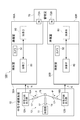
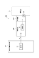
- FIG. 1 is a schematic diagram showing a neutron capture therapy system 100 according to the first embodiment.
- the neutron capture therapy system 100 is a device that performs cancer treatment using boron neutron capture therapy (BNCT).
- Neutron capture therapy performs cancer treatment by irradiating a patient (irradiated body) to which boron ( 10 B) is administered with neutron beams.
- BNCT boron neutron capture therapy
- FIG. 1 is a device that performs cancer treatment using boron neutron capture therapy (BNCT).
- BNCT boron neutron capture therapy
- FIG. 1 is a device that performs cancer treatment using boron neutron capture therapy (BNCT).
- BNCT boron neutron capture therapy
- FIG. 1 is a device that performs cancer treatment using boron neutron capture therapy (BNCT).
- BNCT boron neutron capture therapy
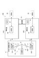
- FIG. 2 is a diagram showing a configuration of the neutron capture therapy system 100.
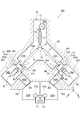
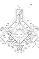
- FIG. 3 is a diagram showing the arrangement of the neutron capture therapy system 100.
- the neutron capture therapy system 100 includes a neutron beam generation unit 10 for generating and irradiating a therapeutic neutron beam N, and an irradiation chamber for irradiating the patient with the neutron beam N.
- the neutron beam generator 10 is configured to generate a neutron beam N in irradiation chambers 30A and 30B, which will be described later, and to irradiate the patient S with the neutron beam N.
- the neutron beam generation unit 10 includes an accelerator 11 (for example, a cyclotron), a neutron beam output unit 12A and a neutron beam output unit 12B that generate a neutron beam N from the charged particle beam P, and a charged particle beam P as a neutron beam output unit 12A.
- the beam transport path 13 transported to the neutron beam output part 12B is provided.
- the accelerator 11 and the beam transport path 13 are arranged in a Y-shaped charged particle beam generation chamber 10a (see FIG. 3).
- the charged particle beam generation chamber 10a is a closed space covered with a concrete shielding wall W.
- the accelerator 11 accelerates charged particles (for example, protons), creates charged particle beams P (for example, proton beams), and emits them.
- the beam transport path 13 selectively emits the charged particle beam P to either the neutron beam output unit 12A or the neutron beam output unit 12B.
- the beam transport path 13 includes a first transport unit 14 connected to the accelerator 11, a beam direction switch 15 that switches the traveling direction of the charged particle beam P, and a transport for transporting the charged particle beam P to the neutron beam output unit 12A. 16 A of 2nd transport parts and the 3rd transport part 16B for transporting the charged particle beam P to the neutron beam output part 12B are provided.
- the second transport unit 16A is connected to the beam direction switch 15 and the neutron beam output unit 12A.
- the third transport unit 16B is connected to the beam direction switch 15 and the neutron beam output unit 12B. That is, the beam transport path 13 branches into the second transport unit 16A and the third transport unit 16B in the beam direction switch 15.
- the beam direction switch 15 controls the traveling direction of the charged particle beam P using a switching electromagnet.
- the beam direction switch 15 can remove the charged particle beam P from the normal trajectory and guide it to a beam dump (not shown). According to the beam dump, the output of the charged particle beam P can be confirmed before treatment or the like.
- the neutron capture therapy system 100 may have a configuration that does not include a beam dump. In this case, the beam direction switch 15 is not connected to the beam dump.
- Each of the first transport unit 14, the second transport unit 16A, and the third transport unit 16B includes a beam adjusting unit 17 for the charged particle beam P.
- the beam adjusting unit 17 is for horizontal and horizontal steering for adjusting the axis of the charged particle beam P, a quadrupole electromagnet for suppressing the divergence of the charged particle beam P, and for shaping the charged particle beam P. Including four-way slits.
- Each of the first transport unit 14, the second transport unit 16 ⁇ / b> A, and the third transport unit 16 ⁇ / b> B may be configured without the beam adjustment unit 17.
- the second transport unit 16A and the third transport unit 16B may include a current monitor as necessary.
- the current monitor measures the current value (that is, charge, irradiation dose rate) of the charged particle beam P irradiated to the neutron beam output unit 12A and the neutron beam output unit 12B in real time.
- the second transport unit 16A and the third transport unit 16B may include a charged particle beam scanning unit 18 (see FIG. 4) as necessary.
- the charged particle beam scanning unit 18 scans the charged particle beam P and controls irradiation of the charged particle beam P to the target T (see FIG. 4).
- the charged particle beam scanning unit 18 controls the irradiation position of the charged particle beam P with respect to the target T, for example.
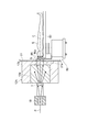
- FIG. 4 is a view showing the vicinity of the neutron beam output unit 12A of the neutron capture therapy system 100.
- the neutron beam output unit 12A and the neutron beam output unit 12B have the same configuration. Accordingly, the neutron beam output unit 12A will be described below, and the description of the neutron beam output unit 12B will be omitted.
- the neutron beam output unit 12A includes a target T for generating the neutron beam N, a moderator 12a for decelerating the neutron beam N, and a shield 12b.
- the moderator 12a and the shielding body 12b constitute a moderator.
- the target T generates a neutron beam N when irradiated with the charged particle beam P.
- the target T is formed of, for example, beryllium (Be) and has a disk shape with a diameter of 160 mm.
- the moderator 12a decelerates the neutron beam N emitted from the target T.
- the neutron beam N decelerated by the moderator 12a and reduced to a predetermined energy is also called a therapeutic neutron beam.
- the moderator 12a has, for example, a laminated structure made of a plurality of different materials.
- the material of the moderator 12a is appropriately selected according to various conditions such as the energy of the charged particle beam P. For example, when the output from the accelerator 11 (see FIG. 2) is a proton beam of 30 MeV and a beryllium target is used as the target T, the material of the moderator 12a is lead, iron, aluminum, or calcium fluoride. be able to.
- the material of the moderator 12a can be heavy water (D2O) or lead fluoride.
- the material of the moderator 12a is fluental (trade name: aluminum, aluminum fluoride, lithium fluoride).
- the material of the moderator 12a can be iron or fluenthal.
- the shield 12b shields the neutron beam N and radiation such as gamma rays generated with the generation of the neutron beam N from being emitted to the outside, and separates the charged particle beam generation chamber 10a from the irradiation chamber 30A. At least a part thereof is embedded in W1 (see FIG. 3).
- the charged particle beam P is irradiated onto the target T, whereby a neutron beam N is generated.
- the generated neutron beam N is decelerated by the moderator 12a.
- the neutron beam N emitted from the moderator 12 a passes through the collimator 86 and is irradiated to the patient S on the treatment table 80.
- the neutron beam N includes a fast neutron beam, an epithermal neutron beam, and a thermal neutron beam, and is accompanied by gamma rays.
- the thermal neutron beam mainly reacts with the boron incorporated into the tumor in the body of the patient S to exert an effective therapeutic effect.
- a part of the epithermal neutron beam included in the beam of neutron beam N also becomes a thermal neutron beam that is decelerated in the body of the patient S and exhibits the above therapeutic effect.
- a thermal neutron beam is a neutron beam having an energy of 0.5 eV or less.
- the neutron capture therapy system 100 includes two irradiation chambers 30A and 30B.
- the irradiation chamber 30A is disposed on an extension line in the direction in which the second transport portion 16A extends.
- the irradiation chamber 30B is disposed on an extension line in the direction in which the third transport portion 16B extends.
- the neutron beam N can also be extracted in a direction intersecting with the direction in which the second transport part 16A or the third transport part 16B extends.
- the arrangement of the irradiation chamber 30A is not limited to the extended line in the direction in which the second transport portion 16A extends, and the irradiation chamber 30A is arranged at a position corresponding to the extraction direction of the neutron beam N. Can do.
- the arrangement of the irradiation chamber 30B is not limited to the extended line in the direction in which the third transport portion 16B extends, and the irradiation chamber 30B can be arranged at a position corresponding to the extraction direction of the neutron beam N.
- the irradiation chamber 30B has the same configuration as the irradiation chamber 30A. Accordingly, the irradiation chamber 30A will be described below, and the description of the irradiation chamber 30B will be omitted.
- the irradiation room 30 ⁇ / b> A is a room in which the patient S is disposed in order to irradiate the patient S with the neutron beam N.
- the size of the irradiation chamber 30A is 3.5 m wide ⁇ 5 m deep ⁇ 3 m high.
- the irradiation chamber 30A includes a shielding space 30S surrounded by the shielding wall W2 and a door D1 for allowing the treatment table 80 to enter and exit.
- a cover (wall body) 31 is provided between the irradiation chamber 30A and the shield 12b.
- the cover 31 forms a part of the side wall surface of the irradiation chamber 30A.
- the cover 31 is provided with a collimator mounting portion 31 a that serves as an output port for the neutron beam N.
- the collimator mounting portion 31a is an opening for fitting a collimator 86 described later.
- the shielding wall W2 forms a shielding space 30S in which radiation is prevented from entering the room from the outside of the irradiation room 30A and radiation is prevented from being emitted from the room to the outside. That is, the shielding wall W2 blocks the radiation of the neutron beam N from the inside of the irradiation chamber 30A to the outside.
- the shielding wall W2 may be formed integrally with the shielding wall W that defines the charged particle beam generation chamber 10a.
- the shielding wall W2 may be a concrete wall having a thickness of 2 m or more.
- a wall W1 separating the charged particle beam generation chamber 10a and the irradiation chamber 30A is provided between the charged particle beam generation chamber 10a and the irradiation chamber 30A. This wall W1 forms a part of the shielding wall W.
- the door D1 is for suppressing radiation in the shielded space 30S from being emitted to the communication room 40A.
- the communication room 40A will be described later.
- the door D1 is provided so as to close an entrance that communicates with the communication chamber 40A.
- the door D1 is made of a radiation shielding member such as lead and has a predetermined thickness.
- the door D1 moves on a rail provided in the room of the irradiation chamber 30A with a driving force applied by a motor or the like. Since the door D1 is heavy, a high torque motor, a speed reducer, or the like is used as a mechanism for driving the door D1. Further, the door D1 may have a function of notifying the worker entering and exiting the irradiation chamber 30A. For example, the retreat of the operator from the irradiation chamber 30A may be confirmed by closing the door D1 in a state where the treatment table 80 is disposed in the irradiation chamber 30A.
- a camera 32 is disposed in the irradiation chamber 30A.
- the camera 32 is for observing the state of the patient S in the room of the irradiation room 30A.
- the camera 32 is arranged at a position where the patient S can be photographed in the irradiation chamber 30A.
- the camera 32 does not need to acquire a high-accuracy image, and only needs to be able to acquire an image that can confirm the state of the patient S.
- a CCD camera can be used as the camera 32.
- the preparation rooms 50A and 50B will be described.
- the neutron capture therapy system 100 includes two preparation rooms 50A and 50B.
- the preparation chamber 50A is arranged so as to be separated from the irradiation chamber 30A along the Y-axis direction.
- the preparation room 50B has the same configuration as the preparation room 50A. Therefore, the preparation room 50A will be described below, and the description of the preparation room 50B will be omitted.
- the preparation room 50A is a room for performing work necessary for irradiating the patient S with the neutron beam N in the irradiation room 30A.
- the preparation room 50A for example, the restraint of the patient S on the treatment table 80 and the alignment between the collimator 86 and the patient S are performed (see FIG. 6). Therefore, the preparation room 50 ⁇ / b> A has a size that allows the treatment table 80 to be arranged and allows an operator to easily perform the preparation work around the treatment table 80.
- a wall W3 separating the preparation chamber 50A and the irradiation chamber 30A is provided between the preparation chamber 50A and the irradiation chamber 30A.
- the thickness of the wall W3 is, for example, 3.2 m. That is, the preparation chamber 50A and the irradiation chamber 30A are separated by 3.2 m along the Y-axis direction.
- the wall W3 is provided with a communication room 40A that communicates from the preparation room 50A to the irradiation room 30A.
- the communication room 40A is a room for moving the treatment table 80 restraining the patient S between the preparation room 50A and the irradiation room 30A.
- the communication room 40A has a width through which the treatment table 80 can pass.
- the communication room 40A has a height that allows an operator to walk through. Therefore, the size of the communication room 40A is, for example, 1.5 m wide ⁇ 3.2 m deep ⁇ 2.0 m high.
- a door D2 is disposed between the preparation room 50A and the communication room 40A.
- a communication chamber 40B is provided on the wall W3 separating the preparation chamber 50B and the irradiation chamber 30B.
- the communication room 40B has the same configuration as the communication room 40A.
- preparation rooms 50A and 50B may be shielded spaces surrounded by the shield walls W like the irradiation rooms 30A and 30B.
- the preparation rooms 50A and 50B may be spaces that are not surrounded by the shielding wall W.
- the neutron capture therapy system 100 includes one management room 70.
- the management room 70 is a room for managing the entire process performed using the neutron capture therapy system 100.
- At least one administrator enters the management room 70 and manages the entire process using a monitoring device disposed in the management room 70 and a control device 71 for operating the neutron beam generation unit 10.
- the manager who has entered the management room 70 visually checks the state of the preparation work in the preparation rooms 50 ⁇ / b> A and 50 ⁇ / b> B from the inside of the management room 70.
- the manager who has entered the management room 70 operates the control device 71 to, for example, a beam transport path so as to irradiate the target T corresponding to the irradiation room 30A to be irradiated with the neutron beam N with the charged particle beam P. 13 is controlled. Furthermore, the manager who has entered the management room 70 operates the control device 71 to control the start and stop of irradiation with the neutron beam N.
- a variety of preparation also before the patient S to enter the preparation room 50A, 50B e.g., PET examination and, like the administration of such boron (10 B)
- the management room 70 may manage the entire process of neutron capture therapy including irradiation treatment by the neutron capture therapy system 100 by managing such preparation steps.
- the management room 70 is disposed between the preparation room 50A and the preparation room 50B so as to be adjacent to the two preparation rooms 50A and 50B.
- the management room 70 is adjacent to the preparation room 50A at one corner and is adjacent to the preparation room 50B at another corner.
- a window 72A for viewing the inside of the preparation room 50A is arranged.
- a window 72B is provided for viewing the inside of the preparation room 50B.
- a monitor 73 for displaying an image of the camera 32 provided in the irradiation chambers 30A and 30B is arranged. The administrator can check the state of the patient S in the irradiation chamber 30 ⁇ / b> A from the camera image displayed on the monitor 73.
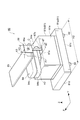
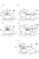
- FIG. 5 is a perspective view showing the treatment table 80 of the neutron capture therapy system 100.
- the treatment table 80 is a mounting table for neutron capture therapy.
- the treatment table 80 is for restraining the patient S to a predetermined posture and moving the patient S from the preparation chamber 50A to the irradiation chamber 30A while restraining the posture.
- the treatment table 80 includes a base part 81, a drive part 82 for moving the base part 81 on the floor surface, and a top board (placement part) 83 for placing the patient S.
- the base part 81 forms a base part of the treatment table 80.
- the base part 81 has a base part 81a and a support part 81b arranged on the base part 81a.
- the base portion 81a has a rectangular shape including a first side 81c and a second side 81d in plan view.
- the first side 81c is longer than the second side 81d.
- the length of at least one of the first side 81c or the second side 81d of the base portion 81a is made smaller than the width of the communication chambers 40A and 40B.
- the support part 81b has a rectangular parallelepiped outer shape.
- the lower surface of the support portion 81b is fixed to the upper surface of the base portion 81a.
- a robot arm 84 and a collimator fixing portion 87 are disposed on the upper surface of the support portion 81b.
- the drive part 82 is provided on the lower surface side of the base part 81 a in the base part 81.
- the drive unit 82 supports all the weights of the base unit 81, the robot arm 84, the top plate 83, the collimator 86, the collimator fixing unit 87, and the patient S, and enables them to move on the floor surface.
- the driving unit 82 can use four wheels. These wheels are given a driving force for movement on the floor surface by a motor or the like.
- the robot arm 84 is for moving the top plate 83 relative to the base portion 81. That is, the robot arm 84 is for moving the patient S restrained on the top plate 83 relative to the collimator 86 fixed to the base portion 81.
- the robot arm 84 includes an elevating part 84a disposed on the upper surface side of the base part 81, a first arm 84b provided with one end side being rotatable about the vertical rotation axis A1 with respect to the elevating part 84a, and one end side being first.
- a second arm 84c provided to be rotatable about the vertical rotation axis A2 with respect to the other end side of the one arm 84b. That is, the robot arm 84 has two vertical rotation axes A1 and A2 that are separated from each other in the horizontal direction.
- the top plate 83 has a flat outer shape having a longitudinal direction.
- the top plate 83 is configured such that the position with respect to the base portion 81 can be adjusted.
- the length of the top plate 83 in the longitudinal direction is set to a length that allows the patient S to lie down, for example, 2 m.
- One end side of the top plate 83 is attached so as to be rotatable around the vertical axis A3 on the other end side of the second arm 84c.
- the top plate 83 is provided with a restraining tool (not shown) for fixing the body of the patient S. Note that the restraining tool may be attached to the top plate 83.
- the first arm 84b is rotated about the vertical rotation axis A1 with respect to the elevating part 84a
- the second arm 84c is rotated about the vertical rotation axis A2 with respect to the first arm 84b.
- the top plate 83 can be moved to a desired position in the XY plane by rotating the top plate 83 about the vertical rotation axis A3 with respect to the second arm 84c.
- the body of the patient S can be rotated around the vertical axis with respect to the irradiation direction of the neutron beam N.
- the top plate 83 can be moved in the Z-axis direction by moving the elevating unit 84a up and down relative to the support unit 81b. Therefore, according to such a robot arm 84, the freedom degree of the posture of the patient S with respect to the collimator 86 fixed to the base part 81 can be improved.
- the collimator 86 is for regulating the irradiation range of the neutron beam N.
- the collimator 86 is provided with, for example, a circular opening 86a for defining an irradiation range.
- a circular opening 86a for defining an irradiation range.
- the upstream and downstream directions of the neutron beam N An imaginary axis extending to is referred to as an “irradiation center axis”, and is denoted by a reference symbol “C”.
- the collimator 86 has, for example, a rectangular flat plate shape.
- the outer shape of the collimator 86 corresponds to the inner shape of the collimator mounting portion 31a in the irradiation chamber 30A.
- the collimator fixing part 87 is fixed to the upper surface of the support part 81 b of the base part 81.
- the collimator fixing portion 87 is for holding the collimator 86 at a fixed position with respect to the base portion 81.
- the collimator fixing portion 87 includes a horizontal piece 87a and an upright piece 87b, and has a substantially L shape.
- One end of the horizontal piece 87a is fixed to the support portion 81b, and the other end projects from the side surface 81e of the support portion 81b in the direction along the X axis.
- the width of the horizontal piece 87a in the horizontal direction (Y axis) is smaller than the width of the base portion 81 in the horizontal direction (Y axis).
- the standing piece 87b has one end fixed to the other end of the horizontal piece 87a and a collimator 86 attached to the other end that extends upward.
- the collimator 86 Since the standing piece 87b is fixed to the horizontal piece 87a that protrudes in the direction along the X axis from the side surface 81e of the base portion 81, the collimator 86 is a position that protrudes in the horizontal direction from the side surface 81e of the base portion 81. Is held in. By holding the collimator 86 at such a position, when the collimator 86 is attached to the collimator attachment portion 31 a of the cover 31, it is possible to suppress the base portion 81, the top plate 83, and the like from interfering with the cover 31.
- the horizontal width H1 of the collimator fixing portion 87 is smaller than the horizontal width H2 of the base portion 81.
- the horizontal width H1 of the collimator fixing portion 87 means the maximum width of the collimator fixing portion 87 in the direction along the Y axis. That is, the width H1 is the maximum width in the direction (Y axis) orthogonal to the direction of the irradiation center axis C (X axis) and the vertical direction (Z axis).
- the horizontal width H2 of the base portion 81 refers to the maximum width of the base portion 81 in the direction along the Y axis. That is, the width H2 is the length of the first side 81c of the base portion 81a.
- the horizontal width H3 of the collimator 86 is smaller than the horizontal width H2 of the base portion 81.
- the horizontal width H3 of the collimator 86 refers to the maximum width of the collimator 86 in the direction along the Y-axis.
- the treatment table 80 is provided with a collimator 86 fixed to the base portion 81 and a top plate 83 that is movable relative to the base portion 81. Therefore, the posture of the patient S restrained on the top plate 83 can be held at a predetermined position with respect to the opening 86a of the collimator 86. Therefore, it becomes possible to irradiate the predetermined irradiation target in the patient S with the neutron beam N that has passed through the opening 86a of the collimator 86.
- the treatment table 80 Since the treatment table 80 is provided with the drive unit 82, the treatment table 80 can be moved while maintaining the posture of the patient S with respect to the collimator 86. Therefore, the alignment between the irradiation target in the patient S and the irradiation center axis C of the collimator 86 can be performed in the preparation chambers 50A and 50B in advance without performing the alignment in the irradiation chamber 30A. In addition, by moving the treatment table 80 to the outside of the irradiation chamber 30A and performing the maintenance of the treatment table 80, it is possible to reduce the work time required for the maintenance of the treatment table 80 in a place with a high radiation dose.
- the maximum width H1 of the collimator fixing portion 87 is equal to or less than the maximum width H2 of the base portion 81. Therefore, the width necessary for the treatment table 80 to pass at the place where the treatment table 80 passes is the base. It is determined by the maximum width H2 of the part 81. Therefore, even if it is a case where incidental equipment is provided in the place where the treatment table 80 passes, it is possible to suppress an increase in the size of the incidental equipment in order to pass the treatment table 80. That is, the expansion of the width of the communication chambers 40A and 40B can be suppressed, and the increase in the size of incidental facilities such as the door D1 and the door D2 can be suppressed.
- the drive mechanism can be simplified.
- the increase in the size of the door D1 and the door D2 is suppressed, and the drive mechanism of the door D1 and the door D2 is simplified, so that an increase in the construction cost of the neutron capture therapy system 100 as a whole can be suppressed.
- the collimator fixing portion 87 protrudes from the side surface 81 e of the base portion 81, so the collimator 86 fixed to the collimator fixing portion 87 is held at a position protruding from the side surface 81 e of the base portion 81. Therefore, when the collimator 86 is attached to the collimator attachment portion 31a of the cover 31, the base portion 81 does not interfere with the cover 31, so that the collimator 86 can be easily attached to the collimator attachment portion 31a.
- the treatment table 80 can adjust the longitudinal direction of the top plate 83 to the moving direction of the treatment table 80 by rotating the top plate 83 around the rotation axes A1, A2, and A3 with respect to the base portion 81. For this reason, the size of the entrance and the like through which the treatment table 80 passes is determined not by the length of the top plate 83 in the longitudinal direction but by the size of the base portion 81. Therefore, the expansion of the size of the doorway through which the treatment table 80 passes can be further suppressed. That is, the width of the communication chambers 40A and 40B in which the treatment table 80 moves is defined by the first side 81c or the second side 81d of the base portion 81 of the treatment table 80.
- [Treatment flow] A flow of treatment using the neutron capture therapy system 100 will be described. First, a predetermined preparation for entering the neutron capture therapy system 100 is performed on the patient S. Subsequently, the patient S and the operator are guided to the preparation room 50 ⁇ / b> A, and the patient S is laid on the top plate 83. And an operator restrains the body of the patient S with respect to the top plate 83 using a restraint tool. Next, the patient S and the collimator 86 are aligned. More specifically, alignment between the irradiation target in the patient S and the irradiation center axis C of the collimator 86 is performed.
- FIG. 6 is a diagram for explaining the alignment between the patient S and the collimator 86.
- the irradiation target R and the irradiation center axis C are shifted in the YZ plane. There is. In this description, it is assumed that the irradiation target R is shifted from the irradiation center axis C by Yd in the Y-axis direction and by Zd in the Z-axis direction. Therefore, as shown in FIGS.
- the operator drives the lifting / lowering portion 84 a of the robot arm 84 to move the top plate 83 by the distance Zd in the Z-axis direction, and the robot arm
- the first arm 84b and the second arm 84c are driven to move the top plate 83 by a distance Yd in the Y-axis direction.
- the robot arm 84 may be driven to adjust the distance along the X-axis direction from the collimator 86 to the irradiation target R.
- the irradiation direction of the neutron beam N on the patient S may be adjusted by rotating the robot arm 84 about the vertical rotation axes A1 to A3 as necessary.
- the state of work performed in the preparation room 50A is monitored by an administrator who has entered the adjacent management room 70.
- the treatment table 80 is moved to the irradiation room 30A.
- the manager of the management room 70 may determine whether or not the irradiation room 30A can be entered. For example, the operator reports to the administrator that the work in the preparation room 50A has been completed. When the manager who has obtained the report determines that it is possible to enter the irradiation room 30A, the manager opens the door D2 that separates the preparation room 50A and the communication room 40A. Then, the operator operates the drive unit 82 of the treatment table 80 to move the treatment table 80 to the communication room 40A. At this time, the worker follows the treatment table 80 and moves to the communication room 40A together with the treatment table 80.
- the manager closes the door D2. After closing, the manager opens the door D1 separating the communication room 40A and the irradiation room 30A.
- the order of opening and closing the doors D1 and D2 is not limited to this order. For example, the door D1 and the door D2 may be opened simultaneously.
- the operator operates the drive unit 82 of the treatment table 80 to move the treatment table 80 into the irradiation chamber 30A, and the operator himself moves into the irradiation chamber 30A.
- the work performed in the irradiation chamber 30A is mainly a work for attaching the collimator 86 to the collimator mounting portion 31a provided in the cover 31 (see FIG. 6E).
- the operator moves to the communication room 40A and closes the door D1 using a switch or the like provided in the communication room 40A. By this closure, it is reported to the management room that the worker has retreated from the irradiation room 30A.
- the manager of the management room 70 After the manager of the management room 70 visually confirms that the worker has evacuated to the preparation room 50A, the manager operates the control device 71 to start irradiation with the neutron beam N.
- the irradiation time is about 1 hour as an example.
- the state of the patient S during irradiation is monitored using the monitor 73 of the management room 70 for the image of the camera 32 provided in the room of the irradiation room 30A.
- the administrator determines to stop irradiation.
- the control device 71 automatically stops the irradiation of the neutron beam N. Then, the operator enters the room of the irradiation room 30A and moves the treatment table 80 to the preparation room 50A. In the room of the preparation room 50A, the fixation of the patient S by the restraining tool is released, and the patient S is guided to the outside of the preparation room 50A. Thus, the neutron capture therapy using the neutron capture therapy system 100 is completed.
- the neutron capture therapy system 100 can selectively irradiate each of the plurality of irradiation chambers 30A and 30B with the neutron beam N. Moreover, according to the neutron capture therapy system 100, since the preparation work for irradiating the patient S with the neutron beam N is performed in the respective preparation rooms 50A and 50B, the time for the preparation work in the irradiation rooms 30A and 30B is performed. Shortened. Therefore, since the ratio of the irradiation time of the neutron beam N in the time when the patient S is arranged in the irradiation chambers 30A and 30B is increased, the utilization efficiency of the irradiation chambers 30A and 30B can be increased.
- neutron capture therapy has a longer irradiation time than radiotherapy such as X-ray therapy or proton beam therapy.
- radiotherapy such as X-ray therapy or proton beam therapy.
- the efficiency improvement by performing the preparatory work in the other irradiation chamber 30 ⁇ / b> B or the preparation chamber 50 ⁇ / b> B is the operating efficiency of the entire system. Contribute greatly to improvement.
- the control for irradiating the irradiation chambers 30A and 30B with the neutron beam N is performed in the one management chamber 70, the adjustment of the neutron beam occupation is made efficient, and the accelerator 11 Can improve the efficiency of use. Therefore, according to the neutron capture therapy system 100, the utilization efficiency of the irradiation chambers 30 ⁇ / b> A and 30 ⁇ / b> B can be increased and the utilization efficiency of the accelerator 11 can be increased, so that the operation efficiency of the entire system can be increased.
- the neutron capture therapy system 100 includes windows 72A and 72B through which the inside of the management room 70 to the preparation rooms 50A and 50B can be observed. According to this configuration, since the inside of each of the preparation rooms 50A and 50B can be observed from the management room 70, the entrance and exit of the patient S with respect to each of the preparation rooms 50A and 50B and the preparation work in the rooms of the preparation rooms 50A and 50B are performed. The degree of progress can be grasped. Therefore, the operating efficiency of the neutron capture therapy system 100 can be further increased.
- the neutron capture therapy system 100 further includes a camera 32 for observing the inside of the irradiation rooms 30A and 30B from the management room 70. According to this configuration, since the inside of each irradiation room 30A, 30B can be observed from the management room 70 through the camera 32, the state of the patient S in each irradiation room 30A, 30B can be grasped. Therefore, the safety of the neutron capture therapy system 100 can be improved.
- the neutron capture therapy system 100 irradiates the treatment table 80 as a preparatory work for irradiating the patient S with the neutron beam N because the treatment table 80 can move between the inside and the outside of the irradiation rooms 30A and 30B. It can be carried out outside the irradiation chambers 30A and 30B after being moved outside the chambers 30A and 30B. Therefore, part of the preparation work in the irradiation chambers 30A and 30B can be performed outside the irradiation chambers 30A and 30B, so that the time required for the preparation work in the irradiation chambers 30A and 30B can be reduced.
- the neutron capture therapy system 100 generates a neutron by irradiating the target T with the charged particle beam P generated by the accelerator 11. According to such a neutron beam generator 10, the neutron capture therapy system 100 can be reduced in size.
- FIG. 7 is a diagram illustrating a configuration of a neutron capture therapy system 101 according to a modification.
- the neutron capture therapy system 101 may include three irradiation chambers 30A, 30B, and 30C and three preparation chambers 50A, 50B, and 50C.
- the neutron beam generation unit 10 includes three neutron beam output units 12A, 12B, and 12C corresponding to the irradiation chambers 30A, 30B, and 30C, respectively.
- the beam transport path 13 includes a second transport unit 16A that transports the charged particle beam P to the neutron beam output unit 12A, a third transport unit 16B that transports the charged particle beam P to the neutron beam output unit 12B, and the charged particle beam P And a fourth transport part 16C for transporting the gas to the neutron beam output part 12C.
- the management room 70 is arranged adjacent to all the preparation rooms 50A, 50B, 50C. Further, a window 72A is provided between the management room 70 and the preparation room 50A, a window 72B is provided between the management room 70 and the preparation room 50B, and between the management room 70 and the preparation room 50C. A window 72C is provided.
- the neutron capture therapy system 101 can achieve the same effects as the neutron capture therapy system 100. That is, in the neutron capture therapy system 101, since the control for selectively irradiating the irradiation chambers 30A, 30B, and 30C with the neutron beam N is performed in the one management chamber 70, the utilization efficiency of the accelerator 11 is increased. Therefore, the operating efficiency of the entire system can be increased.
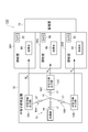
- FIG. 8 is a diagram showing a configuration of the neutron capture therapy system 102 according to the second embodiment.
- the neutron capture therapy system 102 relates to the first embodiment in that it does not include a preparation room and that the management room 70 is disposed adjacent to the two irradiation rooms 30A and 30B. Different from the neutron capture therapy system 100. Since the other configuration is the same as that of the neutron capture therapy system 100, the overlapping description will be omitted below.
- the restraint of the patient S on the treatment table 80 and the alignment of the collimator 86 and the patient S are performed in the preparation rooms 50A and 50B. These operations may be performed at a place different from the preparation chambers 50A and 50B provided in parallel with the irradiation chambers 30A and 30B.
- the treatment table 80 is carried out from the room of the irradiation chambers 30A and 30B surrounded by the shielding wall W to the outside of the room not surrounded by the shielding wall W, and then to a predetermined place. Move.
- the neutron capture therapy system 102 can be configured not to include the preparation rooms 50A and 50B.
- the control for irradiating the irradiation chamber 30A or the irradiation chamber 30B with the neutron beam N is performed in the one management chamber 70, the adjustment of the occupation of the neutron beam N is made efficient and the accelerator 11 Use efficiency can be increased. Therefore, according to the neutron capture therapy system 102, since the utilization efficiency of the accelerator 11 increases, the operating efficiency of the entire system can be increased.
- FIG. 9 is a diagram showing a configuration of a neutron capture therapy system 103 according to a modification.
- the neutron capture therapy system 103 may include three irradiation chambers 30A, 30B, and 30C.
- the neutron beam generation unit 10 includes three neutron beam output units 12A, 12B, and 12C corresponding to the irradiation chambers 30A, 30B, and 30C, respectively.
- the management room 70 is disposed adjacent to all the irradiation rooms 30A, 30B, 30C.
- the neutron capture therapy system 103 can achieve the same effects as the neutron capture therapy system 102. That is, in the neutron capture therapy system 103, since the control for selectively irradiating the irradiation chambers 30A, 30B, and 30C with the neutron beam N is performed in the one management chamber 70, the utilization efficiency of the accelerator 11 is increased. Therefore, the operating efficiency of the entire system can be increased.
- FIG. 10 is a diagram illustrating a configuration of the neutron capture therapy system 104 according to the third embodiment.
- FIG. 11 is a diagram showing the arrangement of the neutron capture therapy system 104.
- the collimator 86 is not attached to the treatment table 80, the collimator 86 is provided in the irradiation chambers 30A and 30B, and the dummy collimator 51 is provided.
- It is different from the neutron capture therapy system 100 according to the first embodiment in that it is provided in the preparation rooms 50A and 50B.
- the configuration different from the neutron capture therapy system 100 according to the first embodiment will be described in detail below.
- the irradiation chambers 30 ⁇ / b> A and 30 ⁇ / b> B have a collimator 86 attached to the collimator attachment portion 31 a of the cover 31.
- the irradiation chambers 30A and 30B include a reference portion (first position defining portion) 33 for positioning the treatment table 80 at a predetermined position in the irradiation chambers 30A and 30B.
- the treatment table 80 can be always arranged at the same position. That is, the position of the treatment table 80 with respect to the collimator 86 can be made constant every time the neutron beam N is irradiated.
- Preparation rooms 50A and 50B have dummy collimators (markers) 51.
- the dummy collimator 51 is a mark for positioning the patient S.
- the dummy collimator 51 has an opening having substantially the same shape as the opening 86a of the collimator 86 in the irradiation chambers 30A and 30B.
- the preparation rooms 50A and 50B have a reference part (second position defining part) 52 for positioning the treatment table 80 at a predetermined position in the preparation rooms 50A and 50B.
- the treatment table 80 can be always arranged at the same position.
- the dummy collimator 51 may not be a three-dimensional object simulating the shape of the collimator 86, but may be a figure representing the shape of the collimator 86 in plan view. For example, it may be a projection image of the collimator 86 projected on the screen. It may be an image of the collimator 86 displayed on the monitor.
- the dummy collimator 51 may be a mark drawn on the wall surface of the preparation chamber 50A.
- the positional relationship of the reference unit 52 with respect to the dummy collimator 51 is the same as the positional relationship of the reference unit 33 with respect to the collimator 86. That is, in the preparation rooms 50A and 50B of the neutron capture therapy system 104, the positional relationship between the collimator 86 and the treatment table 80 in the irradiation rooms 30A and 30B can be simulated.
- performing the alignment of the patient S with respect to the dummy collimator 51 in the preparation chambers 50A and 50B is the same as performing the alignment of the patient S with respect to the collimator 86 in the irradiation chambers 30A and 30B. Has meaning.
- FIG. 12 is a diagram for explaining the alignment between the patient S and the collimator 86.
- the collimator 86 is arranged on the treatment table 80 and the dummy collimator 51 is arranged at the dummy collimator mounting position in the preparation room 50A.
- the collimator 86 and the dummy collimator 51 are prepared for each patient S.
- the treatment table 80 is positioned using the reference portions 52a and 52b, and the treatment table 80 is fixed.
- standard part 52a prescribes
- standard part 52b prescribes
- the patient S is restrained on the top board 83.
- the position of the irradiation target R of the patient S is shifted from the irradiation center axis C of the dummy collimator 51. Therefore, as shown in FIGS. 12 (c) and 12 (d), by operating the elevating part 84a of the treatment table 80 to move the top plate 83 in the direction along the Z axis, the irradiation center axis C and The position in the Z-axis direction with the irradiation target R of the patient S is matched.
- the robot arm 84 of the treatment table 80 is operated to move the top plate 83 in the direction along the XY plane, thereby aligning the positions of the irradiation center axis C and the irradiation target R of the patient S in the Y-axis direction. .
- the treatment table 80 is moved to the irradiation room 30A. And the treatment table 80 is fixed after positioning using the reference
- standard part 33a prescribes
- standard part 33b prescribes
- the state in which the irradiation target R of the patient S is aligned with the position of the irradiation center axis C of the collimator 86 is reproduced.
- the irradiation target R of the patient S is set to the position of the irradiation center axis C of the collimator 86 only by performing the positioning operation using the reference unit 33 in the irradiation chamber 30A. It can be in an aligned state. Therefore, the working time in the irradiation chamber 30A can be shortened.
- the neutron capture therapy system 104 the same effect as the neutron capture therapy system 100 according to the first embodiment can be obtained. That is, since the neutron capture therapy system 104 can perform a part of the work in the irradiation chambers 30A and 30B in the preparation chambers 50A and 50B in advance, the utilization efficiency of the irradiation chambers 30A and 30B can be improved. Further, in the neutron capture therapy system 104, since the control for selectively irradiating the irradiation chambers 30A, 30B, and 30C with the neutron beam N is performed in the one management chamber 70, the utilization efficiency of the accelerator 11 is increased. Therefore, the operating efficiency of the entire system can be increased.
- positioning of the patient S in the irradiation chambers 30A and 30B can be simulated by positioning the patient S with respect to the dummy collimator 51 in the preparation rooms 50A and 50B. Therefore, it is possible to shorten the time for the alignment operation of the patient S in the irradiation chambers 30A and 30B.
- the patient S is positioned with respect to the dummy collimator 51 after the patient S is placed on the treatment table 80 positioned by the reference units 52a and 52b in the preparation rooms 50A and 50B. . Then, when the treatment table 80 on which the patient S is placed is moved to the irradiation chambers 30A and 30B and the position of the treatment table 80 is positioned by the reference portions 33a and 33b, the collimator 86 and the patient S are aligned. Become.
- the alignment operation between the collimator 86 and the patient S in the irradiation chambers 30A and 30B can be performed in the preparation chambers 50A and 50B in a simulated manner, the time required for the alignment operation of the patient S in the irradiation chambers 30A and 30B is reduced. Further shortening is possible.
- the neutron capture therapy system of the present invention has been described above, but the present invention is not limited to the above embodiment.
- the numerical values such as the specific dimensions and distances of the components exemplified in the above embodiment are examples for facilitating the understanding of the description, and do not limit the present invention.
- the treatment table 80 is a chair provided with a seat on which the patient S sits, a backrest erected with respect to the seat, and a head holding unit installed at the upper end of the backrest, instead of the top plate 83. There may be.
- the neutron capture therapy system does not use the neutron beam N generated by the accelerator 11 and the target T, but may use the neutron beam N directly emitted from the nuclear reactor. That is, the neutron beam generation unit 10 may be configured by a nuclear reactor.
- FIG. 13 is a diagram showing a neutron capture therapy system 105 according to a modification. As shown in FIG. 13, in the neutron capture therapy system 105, the neutron beam generation unit 10 includes a nuclear reactor 91 instead of a configuration including an accelerator 11, a beam transport path 13, and neutron beam output units 12 ⁇ / b> A and 12 ⁇ / b> B. Yes. Neutron beam N can be emitted directly from the reactor 91.
- the neutron beam generator 10 having the nuclear reactor 91 it is possible to suppress power consumption required for operation of the neutron capture therapy system. Note that, according to the configuration in which the neutron beam N is generated using the accelerator 11 and the target T as in the first to third embodiments, the size can be reduced as compared with the neutron beam generator 10 having the nuclear reactor 91. it can.
- the neutron beam generation unit 10 may use a radioisotope that emits neutron beams or a small fusion reactor as a neutron source.
- the preparation time in the irradiation chamber can be shortened.
- SYMBOLS 10 ... Neutron beam generation part, 11 ... Accelerator, 12A, 12B, 12C ... Neutron beam output part, 13 ... Beam transport path, 14 ... First transport part, 15 ... Beam direction changer, 16A ... Second transport part, 16B ... 3rd transport part, 16C ... 4th transport part, 17 ... Beam adjustment part, 18 ... Charged particle beam scanning part, 30A, 30B, 30C ... Irradiation chamber, 31 ... Cover (wall body), 32 ... Camera, 33 ... Reference part (first position defining part), 40A, 40B ... communication room, 50A, 50B, 50C ... preparation room, 51 ... dummy collimator (mark), 52 ...
- reference part (second position defining part), 70 ... management room 71 ... Control device, 72A, 72B, 72C ... Window, 73 ... Monitor, 80 ... Treatment table, 81 ... Base part, 82 ... Drive part, 83 ... Top plate, 84 ... Robot arm, 86 ... Collimator, 87 ... Collimator Fixed part, 91 ... nuclear reactor, 00, 101, 102, 103, 104, 105 ... neutron capture therapy system, A1, A2, A3 ... rotation axis, C ... irradiation center axis, D1, D2 ... door, N ... neutron beam, P ... charged particle beam, R ... irradiation target, S ... patient, T ... target, W ... shielding wall, W1, W2, W3 ... wall.
Abstract
Provided is a neutron capture therapy system with which irradiation-chamber preparation time can be shortened. This neutron capture therapy system (100) irradiates a patient (S) with a neutron beam (N). The neutron capture therapy system (100) is provided with: irradiation chambers (30A, 30B) which are each provided with a chamber interior capable of having the patient (S) disposed therein in order to irradiate the patient (S) with the neutron beam (N), and which are surrounded by shielding walls (W1) for blocking chamber-exterior-bound radiation of the neutron beam (N) from the chamber interiors; a neutron beam generation unit (10) which is capable of irradiating the chamber interiors of the irradiation chambers (30A, 30B) with the neutron beam (N); and a treatment table (80) upon which the patient (S) is placed, and which is configured so as to be capable of moving between chamber exteriors and the chamber interiors of the irradiation chambers (30A, 30B).
Description
本発明は、中性子線を被照射体に照射する中性子捕捉療法システムに関する。
The present invention relates to a neutron capture therapy system for irradiating an irradiated object with a neutron beam.
特許文献1には、患者における照射目標に中性子線を照射する中性子線照射装置が記載されている。この中性子線照射装置は、コリメータの中性子取出口と照射目標との位置合わせを容易に行い、照射精度の向上を図ることを可能にする。中性子線照射装置は、患者を載置する載置台と、中性子を減速する減速装置と、中性子を収束するコリメータとを備えている。載置台及びコリメータは、中性子の取出方向に沿って減速装置に対して相対的に移動可能に設けられている。
Patent Document 1 describes a neutron beam irradiation apparatus that irradiates a patient with an irradiation target with a neutron beam. This neutron beam irradiation apparatus can easily align the neutron outlet of the collimator and the irradiation target and improve the irradiation accuracy. The neutron beam irradiation apparatus includes a mounting table on which a patient is mounted, a decelerating apparatus that decelerates neutrons, and a collimator that converges neutrons. The mounting table and the collimator are provided to be movable relative to the speed reducer along the neutron extraction direction.
特許文献1に記載された中性子線照射装置では、減速装置が照射室の壁に埋め込まれ、載置台及びコリメータが照射室内に配置されている。中性子線照射装置を用いて治療を行う場合には、コリメータと載置台上の患者との位置合わせといった準備作業を実施した後に、中性子線を照射する。コリメータ及び載置台は照射室内に配置されているので、位置合わせ作業は照射室内で実施する。
In the neutron beam irradiation apparatus described in Patent Document 1, the speed reducer is embedded in the wall of the irradiation chamber, and the mounting table and the collimator are arranged in the irradiation chamber. When a treatment is performed using a neutron beam irradiation apparatus, a neutron beam is irradiated after performing preparatory work such as alignment between the collimator and the patient on the mounting table. Since the collimator and the mounting table are arranged in the irradiation chamber, the alignment operation is performed in the irradiation chamber.
しかしながら、中性子線を用いた放射線治療法は、他の放射線治療法と比較して、患者に中性子線を照射するための照射室内の放射線量が高くなる傾向がある。したがって、中性子線を用いた放射線治療の分野では、照射室の室内における準備時間を短縮することが望まれている。
However, radiation therapy using neutron radiation tends to have a higher radiation dose in the irradiation chamber for irradiating the patient with neutron radiation than other radiation therapy. Therefore, in the field of radiation therapy using neutron beams, it is desired to shorten the preparation time in the irradiation chamber.
上記事情に鑑み、本発明は、照射室における準備時間を短縮することができる中性子捕捉療法システムを提供することを目的とする。
In view of the above circumstances, an object of the present invention is to provide a neutron capture therapy system that can shorten the preparation time in an irradiation chamber.
本発明の一実施形態に係る中性子捕捉療法システムは、中性子線を被照射体に照射する中性子捕捉療法システムであって、中性子線を被照射体に照射するために被照射体が室内に配置可能であり、室内から室外への中性子線の放射を遮断するための遮蔽壁に覆われた照射室と、照射室の室内に中性子線を照射可能な中性子線発生部と、被照射体を載置し照射室の室内と室外との間で移動可能に構成された載置台と、を備える。
A neutron capture therapy system according to an embodiment of the present invention is a neutron capture therapy system that irradiates an irradiated body with a neutron beam, and the irradiated body can be arranged indoors to irradiate the irradiated body with a neutron beam An irradiation chamber covered with a shielding wall for blocking neutron radiation from the room to the outside of the room, a neutron beam generator capable of emitting neutrons in the room of the irradiation room, and an irradiated object are placed And a mounting table configured to be movable between the inside and the outside of the irradiation chamber.
本発明の一実施形態に係る中性子捕捉療法システムでは、載置台が照射室の室内と室外との間を移動可能であるので、被照射体に中性子線を照射するための準備作業を、載置台を照射室の室外に移動させた後に照射室の室外において実施することができる。従って、照射室の室内における準備作業の一部を照射室の室外で実施できるため、照射室の室内における準備作業に要する時間を短縮することができる。
In the neutron capture therapy system according to one embodiment of the present invention, since the mounting table can move between the inside and the outside of the irradiation chamber, the preparatory work for irradiating the irradiated object with the neutron beam is performed. Can be carried out outside the irradiation chamber after being moved outside the irradiation chamber. Therefore, part of the preparation work in the irradiation chamber can be performed outside the irradiation room, so that the time required for the preparation work in the irradiation chamber can be reduced.
本発明の一実施形態に係る中性子捕捉療法システムは、照射室に並設された準備室を更に備え、準備室の室内には、被照射体の位置合わせのための目印が設けられている。このような構成によれば、準備室において目印に対して被照射体を位置合わせすることにより、照射室における被照射体の位置合わせを模擬することができる。従って、照射室における被照射体の位置合わせ作業の時間を短縮することができる。
The neutron capture therapy system according to an embodiment of the present invention further includes a preparation room arranged in parallel with the irradiation room, and a mark for alignment of the irradiated object is provided in the room of the preparation room. According to such a configuration, the alignment of the irradiated object in the irradiation chamber can be simulated by aligning the irradiated object with respect to the mark in the preparation chamber. Therefore, it is possible to shorten the time required for aligning the irradiated object in the irradiation chamber.
また、照射室の室内には、中性子線の照射範囲を規定するためのコリメータ及び照射室の室内における載置台の位置を規定するための第1位置規定部が設けられ、準備室の室内には、準備室の室内における載置台の位置を規定するための第2位置規定部が更に設けられ、目印と第2位置規定部との間の位置関係は、コリメータと第1位置規定部との間の位置関係と同じである。このような構成によれば、準備室の室内において第2位置規定部により位置決めされた載置台に被照射体を載置した後に、目印に対して被照射体を位置合わせする。そして、被照射体を載置した載置台を照射室に移動させ、載置台の位置を第1位置規定部により位置決めすると、コリメータと被照射体との位置合わせがなされた状態になる。従って、照射室におけるコリメータと被照射体との位置合わせ作業を準備室において模擬的に実施することができるので、照射室における被照射体の位置合わせ作業の時間を更に短縮することができる。
Further, a collimator for defining the irradiation range of the neutron beam and a first position defining unit for defining the position of the mounting table in the room of the irradiation chamber are provided in the room of the irradiation chamber. A second position defining unit for defining the position of the mounting table in the room of the preparation room is further provided, and the positional relationship between the mark and the second position defining unit is between the collimator and the first position defining unit. It is the same as the positional relationship. According to such a configuration, the object to be irradiated is positioned with respect to the mark after the object to be irradiated is placed on the mounting table positioned by the second position defining portion in the preparation room. And if the mounting base which mounted the to-be-irradiated body is moved to an irradiation chamber and the position of a mounting base is positioned by a 1st position prescription | regulation part, it will be in the state by which alignment with the collimator and to-be-irradiated body was made. Accordingly, since the alignment operation between the collimator and the irradiated object in the irradiation chamber can be performed in the preparation chamber in a simulated manner, the time required for the alignment operation of the irradiated object in the irradiation chamber can be further shortened.
また、載置台は、土台部と、土台部上に配置され被照射体を支持する天板と、を有し、天板は、土台部に対して鉛直軸回りに回転可能である。このような構成によれば、土台部に対して天板を回転させることにより、天板の長手方向を載置台の移動方向に合わせることができる。このため、載置台が通過する出入り口等の大きさは、天板部の長手方向の長さではなく、土台部の大きさにより規定されることになる。従って、載置台が通過する出入り口等の大きさの拡大を抑制することができる。
Further, the mounting table has a base part and a top plate that is arranged on the base part and supports the irradiated object, and the top board can rotate around the vertical axis with respect to the base part. According to such a structure, the longitudinal direction of a top plate can be match | combined with the moving direction of a mounting base by rotating a top plate with respect to a base part. For this reason, the size of the entrance and the like through which the mounting table passes is defined by the size of the base portion, not the length of the top plate portion in the longitudinal direction. Therefore, the expansion of the size of the entrance / exit through which the mounting table passes can be suppressed.
本発明の中性子捕捉療法システムによれば、照射室における準備時間を短縮することができる。
According to the neutron capture therapy system of the present invention, the preparation time in the irradiation chamber can be shortened.
以下、図面を参照して本発明の実施形態について詳細に説明する。なお、以下の説明において、同一又は相当要素には同一の符号を付し、重複する説明を省略する。また、後述する中性子線出力部12Aから出射される中性子線Nの出射方向にX軸、中性子線出力部12Aから出射される中性子線Nの出射方向と直交する方向にY軸、床面に対して垂直方向にZ軸を取ったXYZ座標系を設定し(図3参照)、各構成要素の位置関係の説明にX,Y,Zを用いるものとする。
Hereinafter, embodiments of the present invention will be described in detail with reference to the drawings. In the following description, the same or corresponding elements are denoted by the same reference numerals, and redundant description is omitted. Further, with respect to the X axis in the emission direction of neutron beam N emitted from neutron beam output unit 12A described later, the Y axis in the direction perpendicular to the emission direction of neutron beam N emitted from neutron beam output unit 12A, and the floor surface Then, an XYZ coordinate system taking the Z axis in the vertical direction is set (see FIG. 3), and X, Y, and Z are used to describe the positional relationship of each component.
<第1実施形態>
第1実施形態に係る中性子捕捉療法システムについて説明する。図1は、第1実施形態に係る中性子捕捉療法システム100を示す模式図である。中性子捕捉療法システム100は、ホウ素中性子捕捉療法(BNCT:Boron Neutron Capture Therapy)を用いたがん治療を行う装置である。中性子捕捉療法は、ホウ素(10B)が投与された患者(被照射体)に対して中性子線を照射することによりがん治療を行うものである。図1に示すように、中性子捕捉療法システム100を用いた中性子捕捉療法では、患者を治療台(載置台)80に拘束する等の準備作業を準備室50Aの室内で実施し、患者ごと治療台80を照射室30Aへ移動させる。照射室30Aの室内において、患者に中性子線を照射する。 <First Embodiment>
A neutron capture therapy system according to the first embodiment will be described. FIG. 1 is a schematic diagram showing a neutroncapture therapy system 100 according to the first embodiment. The neutron capture therapy system 100 is a device that performs cancer treatment using boron neutron capture therapy (BNCT). Neutron capture therapy performs cancer treatment by irradiating a patient (irradiated body) to which boron ( 10 B) is administered with neutron beams. As shown in FIG. 1, in the neutron capture therapy using the neutron capture therapy system 100, preparatory work such as restraining the patient on the treatment table (mounting table) 80 is performed in the room of the preparation room 50A, and the treatment table for each patient is performed. 80 is moved to the irradiation chamber 30A. The patient is irradiated with neutron beams in the irradiation chamber 30A.
第1実施形態に係る中性子捕捉療法システムについて説明する。図1は、第1実施形態に係る中性子捕捉療法システム100を示す模式図である。中性子捕捉療法システム100は、ホウ素中性子捕捉療法(BNCT:Boron Neutron Capture Therapy)を用いたがん治療を行う装置である。中性子捕捉療法は、ホウ素(10B)が投与された患者(被照射体)に対して中性子線を照射することによりがん治療を行うものである。図1に示すように、中性子捕捉療法システム100を用いた中性子捕捉療法では、患者を治療台(載置台)80に拘束する等の準備作業を準備室50Aの室内で実施し、患者ごと治療台80を照射室30Aへ移動させる。照射室30Aの室内において、患者に中性子線を照射する。 <First Embodiment>
A neutron capture therapy system according to the first embodiment will be described. FIG. 1 is a schematic diagram showing a neutron
図2は、中性子捕捉療法システム100の構成を示す図である。図3は、中性子捕捉療法システム100の配置を示す図である。図2及び図3に示すように、中性子捕捉療法システム100は、治療用の中性子線Nを発生させて照射するための中性子線発生部10と、患者に中性子線Nを照射するための照射室30A,30Bと、照射準備を行うための準備室50A,50Bと、作業工程を管理するための管理室70とを備えている。
FIG. 2 is a diagram showing a configuration of the neutron capture therapy system 100. FIG. 3 is a diagram showing the arrangement of the neutron capture therapy system 100. As shown in FIGS. 2 and 3, the neutron capture therapy system 100 includes a neutron beam generation unit 10 for generating and irradiating a therapeutic neutron beam N, and an irradiation chamber for irradiating the patient with the neutron beam N. 30A, 30B, preparation rooms 50A, 50B for preparing for irradiation, and a management room 70 for managing work processes.
中性子線発生部10は、後述する照射室30A,30Bの室内に中性子線Nを発生させて患者Sへ中性子線Nを照射可能に構成されている。中性子線発生部10は、加速器11(例えば、サイクロトロン)と、荷電粒子線Pから中性子線Nを生成する中性子線出力部12A及び中性子線出力部12Bと、荷電粒子線Pを中性子線出力部12A又は中性子線出力部12Bまで輸送するビーム輸送路13と、を備えている。加速器11及びビーム輸送路13は、Y字状をなす荷電粒子線生成室10aの室内に配置されている(図3参照)。荷電粒子線生成室10aは、コンクリート製の遮蔽壁Wに覆われた閉鎖空間である。
The neutron beam generator 10 is configured to generate a neutron beam N in irradiation chambers 30A and 30B, which will be described later, and to irradiate the patient S with the neutron beam N. The neutron beam generation unit 10 includes an accelerator 11 (for example, a cyclotron), a neutron beam output unit 12A and a neutron beam output unit 12B that generate a neutron beam N from the charged particle beam P, and a charged particle beam P as a neutron beam output unit 12A. Or the beam transport path 13 transported to the neutron beam output part 12B is provided. The accelerator 11 and the beam transport path 13 are arranged in a Y-shaped charged particle beam generation chamber 10a (see FIG. 3). The charged particle beam generation chamber 10a is a closed space covered with a concrete shielding wall W.
加速器11は、荷電粒子(例えば、陽子)を加速して、荷電粒子線P(例えば、陽子線)を作り出し、出射する。加速器11は、例えば、ビーム半径40mm、60kW(=30MeV×2mA)の荷電粒子線Pを生成する能力を有している。
The accelerator 11 accelerates charged particles (for example, protons), creates charged particle beams P (for example, proton beams), and emits them. The accelerator 11 has, for example, the ability to generate a charged particle beam P with a beam radius of 40 mm and 60 kW (= 30 MeV × 2 mA).
ビーム輸送路13は、荷電粒子線Pを中性子線出力部12A又は中性子線出力部12Bのうちのいずれか一方に選択的に出射する。ビーム輸送路13は、加速器11に接続された第1輸送部14と、荷電粒子線Pの進行方向を切り替えるビーム方向切替器15と、荷電粒子線Pを中性子線出力部12Aに輸送するための第2輸送部16Aと、荷電粒子線Pを中性子線出力部12Bに輸送するための第3輸送部16Bと、を有している。第2輸送部16Aは、ビーム方向切替器15及び中性子線出力部12Aに接続されている。第3輸送部16Bは、ビーム方向切替器15及び中性子線出力部12Bに接続されている。すなわち、ビーム輸送路13は、ビーム方向切替器15において第2輸送部16Aと、第3輸送部16Bとに分岐している。
The beam transport path 13 selectively emits the charged particle beam P to either the neutron beam output unit 12A or the neutron beam output unit 12B. The beam transport path 13 includes a first transport unit 14 connected to the accelerator 11, a beam direction switch 15 that switches the traveling direction of the charged particle beam P, and a transport for transporting the charged particle beam P to the neutron beam output unit 12A. 16 A of 2nd transport parts and the 3rd transport part 16B for transporting the charged particle beam P to the neutron beam output part 12B are provided. The second transport unit 16A is connected to the beam direction switch 15 and the neutron beam output unit 12A. The third transport unit 16B is connected to the beam direction switch 15 and the neutron beam output unit 12B. That is, the beam transport path 13 branches into the second transport unit 16A and the third transport unit 16B in the beam direction switch 15.
ビーム方向切替器15は、スイッチング電磁石を利用して荷電粒子線Pの進行方向を制御するものである。なお、ビーム方向切替器15には、荷電粒子線Pを正規の軌道から外してビームダンプ(不図示)に導くことが可能になっている。ビームダンプによれば、治療前などにおいて荷電粒子線Pの出力確認を行うことができる。なお、中性子捕捉療法システム100は、ビームダンプを備えていない構成であってもよく、この場合、ビーム方向切替器15は、ビームダンプには接続されていないことになる。
The beam direction switch 15 controls the traveling direction of the charged particle beam P using a switching electromagnet. The beam direction switch 15 can remove the charged particle beam P from the normal trajectory and guide it to a beam dump (not shown). According to the beam dump, the output of the charged particle beam P can be confirmed before treatment or the like. The neutron capture therapy system 100 may have a configuration that does not include a beam dump. In this case, the beam direction switch 15 is not connected to the beam dump.
第1輸送部14、第2輸送部16A及び第3輸送部16Bのそれぞれは、荷電粒子線Pのためのビーム調整部17を含んでいる。ビーム調整部17は、荷電粒子線Pの軸調整のための水平型ステアリング及び水平垂直型ステアリング、荷電粒子線Pの発散を抑制するための四重極電磁石、及び荷電粒子線Pの整形のための四方向スリット等を含んでいる。なお、第1輸送部14、第2輸送部16A及び第3輸送部16Bのそれぞれは、ビーム調整部17を備えていない構成であってもよい。
Each of the first transport unit 14, the second transport unit 16A, and the third transport unit 16B includes a beam adjusting unit 17 for the charged particle beam P. The beam adjusting unit 17 is for horizontal and horizontal steering for adjusting the axis of the charged particle beam P, a quadrupole electromagnet for suppressing the divergence of the charged particle beam P, and for shaping the charged particle beam P. Including four-way slits. Each of the first transport unit 14, the second transport unit 16 </ b> A, and the third transport unit 16 </ b> B may be configured without the beam adjustment unit 17.
なお、第2輸送部16A及び第3輸送部16Bは、必要に応じて電流モニタを含んでもよい。電流モニタは、中性子線出力部12A及び中性子線出力部12Bに照射される荷電粒子線Pの電流値(つまり、電荷,照射線量率)をリアルタイムで測定するものである。また、第2輸送部16A及び第3輸送部16Bは、必要に応じて荷電粒子線走査部18(図4参照)を含んでもよい。荷電粒子線走査部18は、荷電粒子線Pを走査し、ターゲットT(図4参照)に対する荷電粒子線Pの照射制御を行うものである。荷電粒子線走査部18は、例えば、荷電粒子線PのターゲットTに対する照射位置を制御する。
Note that the second transport unit 16A and the third transport unit 16B may include a current monitor as necessary. The current monitor measures the current value (that is, charge, irradiation dose rate) of the charged particle beam P irradiated to the neutron beam output unit 12A and the neutron beam output unit 12B in real time. Further, the second transport unit 16A and the third transport unit 16B may include a charged particle beam scanning unit 18 (see FIG. 4) as necessary. The charged particle beam scanning unit 18 scans the charged particle beam P and controls irradiation of the charged particle beam P to the target T (see FIG. 4). The charged particle beam scanning unit 18 controls the irradiation position of the charged particle beam P with respect to the target T, for example.
図4は、中性子捕捉療法システム100の中性子線出力部12Aの近傍を示す図である。ここで、中性子線出力部12Aと中性子線出力部12Bとは互いに同様の構成を有する。従って、以下より中性子線出力部12Aについて説明をし、中性子線出力部12Bの説明を省略する。図4に示すように、中性子線出力部12Aは、中性子線Nを生成するためのターゲットTと、中性子線Nを減速するための減速材12aと、遮蔽体12bとを含んでいる。なお、減速材12a及び遮蔽体12bは、モデレータを構成する。
FIG. 4 is a view showing the vicinity of the neutron beam output unit 12A of the neutron capture therapy system 100. FIG. Here, the neutron beam output unit 12A and the neutron beam output unit 12B have the same configuration. Accordingly, the neutron beam output unit 12A will be described below, and the description of the neutron beam output unit 12B will be omitted. As shown in FIG. 4, the neutron beam output unit 12A includes a target T for generating the neutron beam N, a moderator 12a for decelerating the neutron beam N, and a shield 12b. The moderator 12a and the shielding body 12b constitute a moderator.
ターゲットTは、荷電粒子線Pの照射を受けて中性子線Nを発生させるものである。ターゲットTは、例えば、ベリリウム(Be)により形成され、直径160mmの円板状をなしている。
The target T generates a neutron beam N when irradiated with the charged particle beam P. The target T is formed of, for example, beryllium (Be) and has a disk shape with a diameter of 160 mm.
減速材12aは、ターゲットTから出射される中性子線Nを減速させるものである。減速材12aにより減速されて所定のエネルギーに低減された中性子線Nは治療用中性子線とも呼ばれる。減速材12aは、例えば異なる複数の材料から成る積層構造とされている。減速材12aの材料は、荷電粒子線Pのエネルギー等の諸条件によって適宜選択される。例えば、加速器11(図2参照)からの出力が30MeVの陽子線であり、ターゲットTとしてベリリウムターゲットを用いる場合には、減速材12aの材料は、鉛、鉄、アルミニウム、又はフッ化カルシウムとすることができる。また、加速器11からの出力が11MeVの陽子線であり、ターゲットTとしてベリリウムターゲットを用いる場合には、減速材12aの材料は、重水(D2O)又はフッ化鉛とすることができる。また、加速器11からの出力が2.8MeVの陽子線であり、ターゲットTとしてリチウムターゲットを用いる場合には、減速材12aの材料は、フルエンタール(商品名;アルミニウム、フッ化アルミ、フッ化リチウムの混合物)とすることができる。また、加速器11からの出力が50MeVの陽子線であり、ターゲットTとしてタングステンターゲットを用いる場合には、減速材12aの材料は、鉄又はフルエンタールとすることができる。
The moderator 12a decelerates the neutron beam N emitted from the target T. The neutron beam N decelerated by the moderator 12a and reduced to a predetermined energy is also called a therapeutic neutron beam. The moderator 12a has, for example, a laminated structure made of a plurality of different materials. The material of the moderator 12a is appropriately selected according to various conditions such as the energy of the charged particle beam P. For example, when the output from the accelerator 11 (see FIG. 2) is a proton beam of 30 MeV and a beryllium target is used as the target T, the material of the moderator 12a is lead, iron, aluminum, or calcium fluoride. be able to. Moreover, when the output from the accelerator 11 is a proton beam of 11 MeV and a beryllium target is used as the target T, the material of the moderator 12a can be heavy water (D2O) or lead fluoride. Moreover, when the output from the accelerator 11 is a proton beam of 2.8 MeV and a lithium target is used as the target T, the material of the moderator 12a is fluental (trade name: aluminum, aluminum fluoride, lithium fluoride). A mixture of Moreover, when the output from the accelerator 11 is a proton beam of 50 MeV and a tungsten target is used as the target T, the material of the moderator 12a can be iron or fluenthal.
遮蔽体12bは、中性子線N及び当該中性子線Nの発生に伴って生じたガンマ線等の放射線が外部へ放出されないよう遮蔽するものであり、荷電粒子線生成室10aと照射室30Aとを隔てる壁W1(図3参照)に少なくともその一部が埋め込まれている。
The shield 12b shields the neutron beam N and radiation such as gamma rays generated with the generation of the neutron beam N from being emitted to the outside, and separates the charged particle beam generation chamber 10a from the irradiation chamber 30A. At least a part thereof is embedded in W1 (see FIG. 3).
中性子線出力部12Aにおいては、荷電粒子線PがターゲットTに照射され、これにより中性子線Nが発生する。発生した中性子線Nは、減速材12aで減速される。そして、減速材12aから出射された中性子線Nが、コリメータ86を通過して治療台80上の患者Sへ照射される。中性子線N中には、速中性子線、熱外中性子線、及び熱中性子線が含まれており、またガンマ線も伴っている。このうちの熱中性子線が、主に、患者Sの体内の腫瘍中に取り込まれたホウ素と核反応して有効な治療効果を発揮する。なお、中性子線Nのビームに含まれる熱外中性子線の一部も、患者Sの体内で減速されて上記治療効果を発揮する熱中性子線となる。熱中性子線は、0.5eV以下のエネルギーの中性子線である。
In the neutron beam output unit 12A, the charged particle beam P is irradiated onto the target T, whereby a neutron beam N is generated. The generated neutron beam N is decelerated by the moderator 12a. Then, the neutron beam N emitted from the moderator 12 a passes through the collimator 86 and is irradiated to the patient S on the treatment table 80. The neutron beam N includes a fast neutron beam, an epithermal neutron beam, and a thermal neutron beam, and is accompanied by gamma rays. Of these, the thermal neutron beam mainly reacts with the boron incorporated into the tumor in the body of the patient S to exert an effective therapeutic effect. A part of the epithermal neutron beam included in the beam of neutron beam N also becomes a thermal neutron beam that is decelerated in the body of the patient S and exhibits the above therapeutic effect. A thermal neutron beam is a neutron beam having an energy of 0.5 eV or less.
[照射室]
照射室30A,30Bについて説明する。図3に示すように、中性子捕捉療法システム100は、2つの照射室30A,30Bを備えている。照射室30Aは、第2輸送部16Aが延びた方向の延長線上に配置されている。照射室30Bは、第3輸送部16Bが延びた方向の延長線上に配置されている。なお、中性子線Nは、第2輸送部16A又は第3輸送部16Bが延びた方向と交差する方向に取り出すこともできる。この場合には、照射室30Aの配置は、第2輸送部16Aが延びた方向の延長線上に制限されることはなく、中性子線Nの取り出し方向に対応する位置に照射室30Aを配置することができる。同様に、照射室30Bの配置も、第3輸送部16Bが延びた方向の延長線上に制限されることはなく、中性子線Nの取り出し方向に対応する位置に照射室30Bを配置することができる。ここで、照射室30Bは照射室30Aと同様の構成を有する。従って、以下より照射室30Aについて説明し、照射室30Bの説明を省略する。 [Irradiation room]
The irradiation chambers 30A and 30B will be described. As shown in FIG. 3, the neutron capture therapy system 100 includes two irradiation chambers 30A and 30B. The irradiation chamber 30A is disposed on an extension line in the direction in which the second transport portion 16A extends. The irradiation chamber 30B is disposed on an extension line in the direction in which the third transport portion 16B extends. The neutron beam N can also be extracted in a direction intersecting with the direction in which the second transport part 16A or the third transport part 16B extends. In this case, the arrangement of the irradiation chamber 30A is not limited to the extended line in the direction in which the second transport portion 16A extends, and the irradiation chamber 30A is arranged at a position corresponding to the extraction direction of the neutron beam N. Can do. Similarly, the arrangement of the irradiation chamber 30B is not limited to the extended line in the direction in which the third transport portion 16B extends, and the irradiation chamber 30B can be arranged at a position corresponding to the extraction direction of the neutron beam N. . Here, the irradiation chamber 30B has the same configuration as the irradiation chamber 30A. Accordingly, the irradiation chamber 30A will be described below, and the description of the irradiation chamber 30B will be omitted.
照射室30A,30Bについて説明する。図3に示すように、中性子捕捉療法システム100は、2つの照射室30A,30Bを備えている。照射室30Aは、第2輸送部16Aが延びた方向の延長線上に配置されている。照射室30Bは、第3輸送部16Bが延びた方向の延長線上に配置されている。なお、中性子線Nは、第2輸送部16A又は第3輸送部16Bが延びた方向と交差する方向に取り出すこともできる。この場合には、照射室30Aの配置は、第2輸送部16Aが延びた方向の延長線上に制限されることはなく、中性子線Nの取り出し方向に対応する位置に照射室30Aを配置することができる。同様に、照射室30Bの配置も、第3輸送部16Bが延びた方向の延長線上に制限されることはなく、中性子線Nの取り出し方向に対応する位置に照射室30Bを配置することができる。ここで、照射室30Bは照射室30Aと同様の構成を有する。従って、以下より照射室30Aについて説明し、照射室30Bの説明を省略する。 [Irradiation room]
The
照射室30Aは、中性子線Nを患者Sに照射するために、患者Sが室内に配置される部屋である。照射室30Aの大きさは、一例として幅3.5m×奥行5m×高さ3mである。照射室30Aは、遮蔽壁W2に囲まれた遮蔽空間30Sと、治療台80を出入りさせるための扉D1とを備えている。
The irradiation room 30 </ b> A is a room in which the patient S is disposed in order to irradiate the patient S with the neutron beam N. As an example, the size of the irradiation chamber 30A is 3.5 m wide × 5 m deep × 3 m high. The irradiation chamber 30A includes a shielding space 30S surrounded by the shielding wall W2 and a door D1 for allowing the treatment table 80 to enter and exit.
また、図4に示すように、照射室30Aと遮蔽体12bとの間には、カバー(壁体)31が設けられている。カバー31は、照射室30Aの側壁面の一部をなす。このカバー31には、中性子線Nの出力口となるコリメータ取付部31aが設けられている。コリメータ取付部31aは、後述するコリメータ86をはめ込むための開口である。
Further, as shown in FIG. 4, a cover (wall body) 31 is provided between the irradiation chamber 30A and the shield 12b. The cover 31 forms a part of the side wall surface of the irradiation chamber 30A. The cover 31 is provided with a collimator mounting portion 31 a that serves as an output port for the neutron beam N. The collimator mounting portion 31a is an opening for fitting a collimator 86 described later.
図3に示すように、遮蔽壁W2は、照射室30Aの室外から室内へ放射線が侵入すること、及び、室内から室外へ放射線が放出されることが抑制された遮蔽空間30Sを形成する。すなわち、遮蔽壁W2は、照射室30Aの室内から室外への中性子線Nの放射を遮断するものである。この遮蔽壁W2は、荷電粒子線生成室10aを画成する遮蔽壁Wと一体に形成されていてもよい。また、遮蔽壁W2は、厚さが2m以上のコンクリート製の壁であってもよい。荷電粒子線生成室10aと照射室30Aの間には、荷電粒子線生成室10aと照射室30Aとを隔てる壁W1が設けられている。この壁W1は、遮蔽壁Wの一部をなしている。
As shown in FIG. 3, the shielding wall W2 forms a shielding space 30S in which radiation is prevented from entering the room from the outside of the irradiation room 30A and radiation is prevented from being emitted from the room to the outside. That is, the shielding wall W2 blocks the radiation of the neutron beam N from the inside of the irradiation chamber 30A to the outside. The shielding wall W2 may be formed integrally with the shielding wall W that defines the charged particle beam generation chamber 10a. The shielding wall W2 may be a concrete wall having a thickness of 2 m or more. A wall W1 separating the charged particle beam generation chamber 10a and the irradiation chamber 30A is provided between the charged particle beam generation chamber 10a and the irradiation chamber 30A. This wall W1 forms a part of the shielding wall W.
扉D1は、遮蔽空間30Sにおける放射線が連絡室40Aに放射されることを抑制するためのものである。連絡室40Aについては後述する。扉D1は、連絡室40Aに連通する出入口を塞ぐように設けられている。扉D1は、鉛等の放射線遮蔽部材からなるとともに所定の厚さを有している。扉D1は、照射室30Aの室内に設けられたレール上をモータ等により駆動力を与えられて移動する。扉D1が重量物であるため、扉D1を駆動するための機構には、高トルクモータや減速器等が用いられる。また、扉D1は、照射室30Aへの作業者の出入りを報知する機能を有していてもよい。例えば、照射室30Aの室内に治療台80が配置された状態で、扉D1を閉めることにより照射室30Aからの作業者の退避を確認するものであってもよい。
The door D1 is for suppressing radiation in the shielded space 30S from being emitted to the communication room 40A. The communication room 40A will be described later. The door D1 is provided so as to close an entrance that communicates with the communication chamber 40A. The door D1 is made of a radiation shielding member such as lead and has a predetermined thickness. The door D1 moves on a rail provided in the room of the irradiation chamber 30A with a driving force applied by a motor or the like. Since the door D1 is heavy, a high torque motor, a speed reducer, or the like is used as a mechanism for driving the door D1. Further, the door D1 may have a function of notifying the worker entering and exiting the irradiation chamber 30A. For example, the retreat of the operator from the irradiation chamber 30A may be confirmed by closing the door D1 in a state where the treatment table 80 is disposed in the irradiation chamber 30A.
また、照射室30Aの室内には、カメラ32が配置されている。カメラ32は、照射室30Aの室内における患者Sの様子を観察するためのものである。カメラ32は、照射室30Aの室内において患者Sを撮影可能な位置に配置されている。カメラ32は、高精度の画像を取得する必要はなく、患者Sの状態を確認可能な画像を取得できればよい。カメラ32には、例えばCCDカメラを用いることができる。
Further, a camera 32 is disposed in the irradiation chamber 30A. The camera 32 is for observing the state of the patient S in the room of the irradiation room 30A. The camera 32 is arranged at a position where the patient S can be photographed in the irradiation chamber 30A. The camera 32 does not need to acquire a high-accuracy image, and only needs to be able to acquire an image that can confirm the state of the patient S. As the camera 32, for example, a CCD camera can be used.
[準備室]
準備室50A,50Bについて説明する。中性子捕捉療法システム100は、2つの準備室50A,50Bを備えている。準備室50Aは、Y軸方向に沿って照射室30Aから離間するように配置されている。ここで、準備室50Bは準備室50Aと同様の構成を有する。従って、以下より準備室50Aについて説明し準備室50Bの説明を省略する。 [Preparation room]
The preparation rooms 50A and 50B will be described. The neutron capture therapy system 100 includes two preparation rooms 50A and 50B. The preparation chamber 50A is arranged so as to be separated from the irradiation chamber 30A along the Y-axis direction. Here, the preparation room 50B has the same configuration as the preparation room 50A. Therefore, the preparation room 50A will be described below, and the description of the preparation room 50B will be omitted.
準備室50A,50Bについて説明する。中性子捕捉療法システム100は、2つの準備室50A,50Bを備えている。準備室50Aは、Y軸方向に沿って照射室30Aから離間するように配置されている。ここで、準備室50Bは準備室50Aと同様の構成を有する。従って、以下より準備室50Aについて説明し準備室50Bの説明を省略する。 [Preparation room]
The
準備室50Aは、照射室30Aおいて患者Sに中性子線Nを照射するために必要な作業を実施するための部屋である。準備室50Aでは、例えば、治療台80への患者Sの拘束や、コリメータ86と患者Sとの位置合わせが実施される(図6参照)。従って、準備室50Aは、治療台80が配置可能であり、治療台80の周囲で作業者が容易に準備作業をすることができる程度の大きさを有している。
The preparation room 50A is a room for performing work necessary for irradiating the patient S with the neutron beam N in the irradiation room 30A. In the preparation room 50A, for example, the restraint of the patient S on the treatment table 80 and the alignment between the collimator 86 and the patient S are performed (see FIG. 6). Therefore, the preparation room 50 </ b> A has a size that allows the treatment table 80 to be arranged and allows an operator to easily perform the preparation work around the treatment table 80.
準備室50Aと照射室30Aとの間には、準備室50Aと照射室30Aとを隔てる壁W3が設けられている。壁W3の厚さは、例えば3.2mである。すなわち、準備室50Aと照射室30Aとは、Y軸方向に沿って3.2mだけ離間している。
A wall W3 separating the preparation chamber 50A and the irradiation chamber 30A is provided between the preparation chamber 50A and the irradiation chamber 30A. The thickness of the wall W3 is, for example, 3.2 m. That is, the preparation chamber 50A and the irradiation chamber 30A are separated by 3.2 m along the Y-axis direction.
壁W3には、準備室50Aから照射室30Aまで連通する連絡室40Aが設けられている。連絡室40Aは、患者Sを拘束した治療台80を準備室50Aと照射室30Aとの間で移動させるための部屋である。連絡室40Aは、治療台80が通過可能な幅を有している。また、連絡室40Aは、作業者が歩いて通行可能な高さを有している。従って、連絡室40Aの大きさは、一例として幅1.5m×奥行3.2m×高さ2.0mである。準備室50Aと連絡室40Aとの間には、扉D2が配置されている。なお、準備室50Bと照射室30Bとを隔てる壁W3には、連絡室40Bが設けられている。連絡室40Bは連絡室40Aと同様の構成を有する。
The wall W3 is provided with a communication room 40A that communicates from the preparation room 50A to the irradiation room 30A. The communication room 40A is a room for moving the treatment table 80 restraining the patient S between the preparation room 50A and the irradiation room 30A. The communication room 40A has a width through which the treatment table 80 can pass. In addition, the communication room 40A has a height that allows an operator to walk through. Therefore, the size of the communication room 40A is, for example, 1.5 m wide × 3.2 m deep × 2.0 m high. A door D2 is disposed between the preparation room 50A and the communication room 40A. Note that a communication chamber 40B is provided on the wall W3 separating the preparation chamber 50B and the irradiation chamber 30B. The communication room 40B has the same configuration as the communication room 40A.
なお、準備室50A,50Bは、照射室30A,30Bのように遮蔽壁Wに囲まれた遮蔽空間であってもよい。また、準備室50A,50Bは、遮蔽壁Wに囲まれていない空間であってもよい。
Note that the preparation rooms 50A and 50B may be shielded spaces surrounded by the shield walls W like the irradiation rooms 30A and 30B. The preparation rooms 50A and 50B may be spaces that are not surrounded by the shielding wall W.
[管理室]
中性子捕捉療法システム100は、1つの管理室70を備えている。管理室70は、中性子捕捉療法システム100を用いて実施される全体工程を管理するための部屋である。管理室70には、少なくとも1名の管理者が入室し、管理室70の室内に配置された監視機器及び中性子線発生部10を操作するための制御装置71を用いて全体工程を管理する。例えば、管理室70に入室した管理者は、準備室50A,50Bにおける準備作業の様子を管理室70の室内から目視により確認する。また、管理室70に入室した管理者は、制御装置71を操作して、例えば、中性子線Nを照射すべき照射室30Aに対応するターゲットTに荷電粒子線Pを照射するようにビーム輸送路13を制御する。さらに、管理室70に入室した管理者は、制御装置71を操作して、中性子線Nの照射の開始と停止とを制御する。なお、中性子捕捉療法では、患者Sには準備室50A,50Bに入室する前にも種々の準備(例えば、PET検査や、ホウ素(10B)等の投与など)が行われる。管理室70では、このような前準備の工程も管理することにより、中性子捕捉療法システム100による照射治療を含めた中性子捕捉療法の全体工程を管理するものであってもよい。 [Management room]
The neutroncapture therapy system 100 includes one management room 70. The management room 70 is a room for managing the entire process performed using the neutron capture therapy system 100. At least one administrator enters the management room 70 and manages the entire process using a monitoring device disposed in the management room 70 and a control device 71 for operating the neutron beam generation unit 10. For example, the manager who has entered the management room 70 visually checks the state of the preparation work in the preparation rooms 50 </ b> A and 50 </ b> B from the inside of the management room 70. Further, the manager who has entered the management room 70 operates the control device 71 to, for example, a beam transport path so as to irradiate the target T corresponding to the irradiation room 30A to be irradiated with the neutron beam N with the charged particle beam P. 13 is controlled. Furthermore, the manager who has entered the management room 70 operates the control device 71 to control the start and stop of irradiation with the neutron beam N. In the neutron capture therapy, a variety of preparation also before the patient S to enter the preparation room 50A, 50B (e.g., PET examination and, like the administration of such boron (10 B)) is performed. The management room 70 may manage the entire process of neutron capture therapy including irradiation treatment by the neutron capture therapy system 100 by managing such preparation steps.
中性子捕捉療法システム100は、1つの管理室70を備えている。管理室70は、中性子捕捉療法システム100を用いて実施される全体工程を管理するための部屋である。管理室70には、少なくとも1名の管理者が入室し、管理室70の室内に配置された監視機器及び中性子線発生部10を操作するための制御装置71を用いて全体工程を管理する。例えば、管理室70に入室した管理者は、準備室50A,50Bにおける準備作業の様子を管理室70の室内から目視により確認する。また、管理室70に入室した管理者は、制御装置71を操作して、例えば、中性子線Nを照射すべき照射室30Aに対応するターゲットTに荷電粒子線Pを照射するようにビーム輸送路13を制御する。さらに、管理室70に入室した管理者は、制御装置71を操作して、中性子線Nの照射の開始と停止とを制御する。なお、中性子捕捉療法では、患者Sには準備室50A,50Bに入室する前にも種々の準備(例えば、PET検査や、ホウ素(10B)等の投与など)が行われる。管理室70では、このような前準備の工程も管理することにより、中性子捕捉療法システム100による照射治療を含めた中性子捕捉療法の全体工程を管理するものであってもよい。 [Management room]
The neutron
管理室70は、2つの準備室50A,50Bに隣接するように、準備室50Aと準備室50Bとの間に配置されている。管理室70は、一の角部において準備室50Aと隣接し、別の角部において準備室50Bと隣接している。管理室70と準備室50Aとの間には、準備室50Aの室内を目視するための窓72Aが配置されている。管理室70と準備室50Bとの間には、準備室50Bの室内を目視するための窓72Bが配置されている。管理室70には、照射室30A,30Bの室内に設けられたカメラ32の画像を表示するためのモニタ73が配置されている。管理者は、このモニタ73に表示されたカメラ画像により、照射室30Aの室内における患者Sの様子を確認することができる。
The management room 70 is disposed between the preparation room 50A and the preparation room 50B so as to be adjacent to the two preparation rooms 50A and 50B. The management room 70 is adjacent to the preparation room 50A at one corner and is adjacent to the preparation room 50B at another corner. Between the management room 70 and the preparation room 50A, a window 72A for viewing the inside of the preparation room 50A is arranged. Between the management room 70 and the preparation room 50B, a window 72B is provided for viewing the inside of the preparation room 50B. In the management room 70, a monitor 73 for displaying an image of the camera 32 provided in the irradiation chambers 30A and 30B is arranged. The administrator can check the state of the patient S in the irradiation chamber 30 </ b> A from the camera image displayed on the monitor 73.
[治療台]
治療台(載置台)80について説明をする。図5は、中性子捕捉療法システム100の治療台80を示す斜視図である。治療台80は、中性子捕捉療法用の載置台である。治療台80は、患者Sを所定の姿勢に拘束すると共に、姿勢を拘束したまま準備室50Aから照射室30Aへ移動させるためのものである。図5に示すように、治療台80は、土台部81と、土台部81を床面上で移動させるための駆動部82と、患者Sを載置するための天板(載置部)83と、天板83を土台部81に対して相対的に移動させるためのロボットアーム84と、中性子線Nの照射視野を規定するためのコリメータ86と、コリメータ86を土台部81に固定するためのコリメータ固定部87とを備えている。 [Treatment table]
The treatment table (mounting table) 80 will be described. FIG. 5 is a perspective view showing the treatment table 80 of the neutroncapture therapy system 100. The treatment table 80 is a mounting table for neutron capture therapy. The treatment table 80 is for restraining the patient S to a predetermined posture and moving the patient S from the preparation chamber 50A to the irradiation chamber 30A while restraining the posture. As shown in FIG. 5, the treatment table 80 includes a base part 81, a drive part 82 for moving the base part 81 on the floor surface, and a top board (placement part) 83 for placing the patient S. A robot arm 84 for moving the top plate 83 relative to the base 81, a collimator 86 for defining the irradiation field of the neutron beam N, and for fixing the collimator 86 to the base 81 And a collimator fixing portion 87.
治療台(載置台)80について説明をする。図5は、中性子捕捉療法システム100の治療台80を示す斜視図である。治療台80は、中性子捕捉療法用の載置台である。治療台80は、患者Sを所定の姿勢に拘束すると共に、姿勢を拘束したまま準備室50Aから照射室30Aへ移動させるためのものである。図5に示すように、治療台80は、土台部81と、土台部81を床面上で移動させるための駆動部82と、患者Sを載置するための天板(載置部)83と、天板83を土台部81に対して相対的に移動させるためのロボットアーム84と、中性子線Nの照射視野を規定するためのコリメータ86と、コリメータ86を土台部81に固定するためのコリメータ固定部87とを備えている。 [Treatment table]
The treatment table (mounting table) 80 will be described. FIG. 5 is a perspective view showing the treatment table 80 of the neutron
土台部81は、治療台80の基体部をなす。土台部81は、基礎部81aと基礎部81a上に配置された支持部81bとを有している。基礎部81aは、平面視して第1の辺81cと第2の辺81dとを含む矩形状の形状を有している。例えば、第1の辺81cは、第2の辺81dよりも長くされている。この基礎部81aの第1の辺81c又は第2の辺81dの少なくとも一方の長さは、連絡室40A,40Bの幅よりも小さくされている。支持部81bは、直方体状の外形形状を有している。支持部81bの下面は基礎部81aの上面に固定されている。支持部81bの上面には、ロボットアーム84とコリメータ固定部87とが配置されている。
The base part 81 forms a base part of the treatment table 80. The base part 81 has a base part 81a and a support part 81b arranged on the base part 81a. The base portion 81a has a rectangular shape including a first side 81c and a second side 81d in plan view. For example, the first side 81c is longer than the second side 81d. The length of at least one of the first side 81c or the second side 81d of the base portion 81a is made smaller than the width of the communication chambers 40A and 40B. The support part 81b has a rectangular parallelepiped outer shape. The lower surface of the support portion 81b is fixed to the upper surface of the base portion 81a. A robot arm 84 and a collimator fixing portion 87 are disposed on the upper surface of the support portion 81b.
駆動部82は、土台部81における基礎部81aの下面側に設けられている。駆動部82は、土台部81、ロボットアーム84、天板83、コリメータ86、コリメータ固定部87及び患者Sの全ての重量を支持すると共に、それらを床面上で移動可能にする。駆動部82は、例えば、4つの車輪を用いることができる。これら車輪には、床面上で移動させるための駆動力がモータ等により与えられる。
The drive part 82 is provided on the lower surface side of the base part 81 a in the base part 81. The drive unit 82 supports all the weights of the base unit 81, the robot arm 84, the top plate 83, the collimator 86, the collimator fixing unit 87, and the patient S, and enables them to move on the floor surface. For example, the driving unit 82 can use four wheels. These wheels are given a driving force for movement on the floor surface by a motor or the like.
ロボットアーム84は、天板83を土台部81に対して相対的に移動させるためのものである。すなわち、ロボットアーム84は、天板83の上に拘束された患者Sを、土台部81に固定されたコリメータ86に対して相対的に移動させるためのものである。床面から天板83までの高さには特に制限はないが、天板83上の患者Sの拘束等を容易に実施できる程度の高さに設定されていることが好ましい。ロボットアーム84は、土台部81の上面側に配置された昇降部84aと、一端側が昇降部84aに対して鉛直回転軸A1回りに回転可能に設けられた第1のアーム84bと、一端側が第1のアーム84bの他端側に対して鉛直回転軸A2回りに回転可能に設けられた第2のアーム84cと、を含んでいる。すなわち、ロボットアーム84は、水平方向に互いに離間した2つの鉛直回転軸A1,A2を有している。
The robot arm 84 is for moving the top plate 83 relative to the base portion 81. That is, the robot arm 84 is for moving the patient S restrained on the top plate 83 relative to the collimator 86 fixed to the base portion 81. Although there is no restriction | limiting in particular in the height from a floor surface to the top plate 83, It is preferable to set to the height which can perform restraint etc. of the patient S on the top plate 83 easily. The robot arm 84 includes an elevating part 84a disposed on the upper surface side of the base part 81, a first arm 84b provided with one end side being rotatable about the vertical rotation axis A1 with respect to the elevating part 84a, and one end side being first. And a second arm 84c provided to be rotatable about the vertical rotation axis A2 with respect to the other end side of the one arm 84b. That is, the robot arm 84 has two vertical rotation axes A1 and A2 that are separated from each other in the horizontal direction.
天板83は、長手方向を有する平板状の外形形状を有している。この天板83は、土台部81に対する位置が調整可能に構成されている。天板83の長手方向の長さは、患者Sが身体を横たえることが可能な長さ、例えば2mの長さとされている。天板83の一端側は、第2のアーム84cの他端側において鉛直軸A3回りに回転可能に取り付けられている。この天板83には、患者Sの体を固定するための拘束具(不図示)が設けられている。なお、拘束具は、天板83に取り付けられていてもよい。
The top plate 83 has a flat outer shape having a longitudinal direction. The top plate 83 is configured such that the position with respect to the base portion 81 can be adjusted. The length of the top plate 83 in the longitudinal direction is set to a length that allows the patient S to lie down, for example, 2 m. One end side of the top plate 83 is attached so as to be rotatable around the vertical axis A3 on the other end side of the second arm 84c. The top plate 83 is provided with a restraining tool (not shown) for fixing the body of the patient S. Note that the restraining tool may be attached to the top plate 83.
このようなロボットアーム84によれば、第1のアーム84bを昇降部84aに対して鉛直回転軸A1回りに回転させ、第2のアーム84cを第1のアーム84bに対して鉛直回転軸A2回りに回転させ、天板83を第2のアーム84cに対して鉛直回転軸A3回りに回転させることにより、XY平面内において所望の位置に天板83を移動させることができる。さらに、中性子線Nの照射方向に対して患者Sの身体を鉛直軸回りに回転させることができる。また、昇降部84aを支持部81bに対して上下動させることにより、天板83をZ軸方向に移動させることができる。従って、このようなロボットアーム84によれば、土台部81に固定されたコリメータ86に対する患者Sの姿勢の自由度を高めることができる。
According to such a robot arm 84, the first arm 84b is rotated about the vertical rotation axis A1 with respect to the elevating part 84a, and the second arm 84c is rotated about the vertical rotation axis A2 with respect to the first arm 84b. The top plate 83 can be moved to a desired position in the XY plane by rotating the top plate 83 about the vertical rotation axis A3 with respect to the second arm 84c. Furthermore, the body of the patient S can be rotated around the vertical axis with respect to the irradiation direction of the neutron beam N. Further, the top plate 83 can be moved in the Z-axis direction by moving the elevating unit 84a up and down relative to the support unit 81b. Therefore, according to such a robot arm 84, the freedom degree of the posture of the patient S with respect to the collimator 86 fixed to the base part 81 can be improved.
コリメータ86は、中性子線Nの照射範囲を規制するためのものである。コリメータ86には、照射範囲を規定するための例えば円形の開口86aが設けられている。以下、コリメータ86で規定される照射野の中心(開口86aの中心)を通り、治療台80を照射室30A,30Bに配置して中性子線Nを照射したときに、中性子線Nの上下流方向に延在する仮想の軸線を「照射中心軸線」と称し、符号「C」を付して示す。また、コリメータ86は、例えば四角形の平板状をなしている。コリメータ86の外形形状は、照射室30Aにおけるコリメータ取付部31aの内面形状に対応している。
The collimator 86 is for regulating the irradiation range of the neutron beam N. The collimator 86 is provided with, for example, a circular opening 86a for defining an irradiation range. Hereinafter, when the treatment table 80 is placed in the irradiation chambers 30A and 30B and irradiated with the neutron beam N through the center of the irradiation field defined by the collimator 86, the upstream and downstream directions of the neutron beam N An imaginary axis extending to is referred to as an “irradiation center axis”, and is denoted by a reference symbol “C”. Further, the collimator 86 has, for example, a rectangular flat plate shape. The outer shape of the collimator 86 corresponds to the inner shape of the collimator mounting portion 31a in the irradiation chamber 30A.
コリメータ固定部87は、土台部81の支持部81bにおける上面に固定されている。コリメータ固定部87は、コリメータ86を土台部81に対して一定の位置に保持するためのものである。コリメータ固定部87は、水平片87aと起立片87bとを有し、略L字状の形状をなしている。水平片87aは、一端部が支持部81bに固定され、他端部が支持部81bの側面81eからX軸に沿った方向に突出している。水平片87aの水平方向(Y軸)の幅は、土台部81の水平方向(Y軸)の幅よりも小さくされている。起立片87bは、一端部が水平片87aの他端部に固定され上方向に延びた先の他端部にはコリメータ86が取り付けられている。
The collimator fixing part 87 is fixed to the upper surface of the support part 81 b of the base part 81. The collimator fixing portion 87 is for holding the collimator 86 at a fixed position with respect to the base portion 81. The collimator fixing portion 87 includes a horizontal piece 87a and an upright piece 87b, and has a substantially L shape. One end of the horizontal piece 87a is fixed to the support portion 81b, and the other end projects from the side surface 81e of the support portion 81b in the direction along the X axis. The width of the horizontal piece 87a in the horizontal direction (Y axis) is smaller than the width of the base portion 81 in the horizontal direction (Y axis). The standing piece 87b has one end fixed to the other end of the horizontal piece 87a and a collimator 86 attached to the other end that extends upward.
起立片87bは、土台部81の側面81eよりもX軸に沿った方向に突出した水平片87aに固定されているので、コリメータ86は、土台部81の側面81eよりも水平方向に突出した位置に保持されている。このような位置にコリメータ86を保持することにより、コリメータ86をカバー31のコリメータ取付部31aに取り付ける際に、土台部81及び天板83等がカバー31に干渉することを抑制することができる。
Since the standing piece 87b is fixed to the horizontal piece 87a that protrudes in the direction along the X axis from the side surface 81e of the base portion 81, the collimator 86 is a position that protrudes in the horizontal direction from the side surface 81e of the base portion 81. Is held in. By holding the collimator 86 at such a position, when the collimator 86 is attached to the collimator attachment portion 31 a of the cover 31, it is possible to suppress the base portion 81, the top plate 83, and the like from interfering with the cover 31.
コリメータ固定部87の水平方向の幅H1は、土台部81の水平方向の幅H2よりも小さくされている。ここで、コリメータ固定部87の水平方向の幅H1とは、Y軸に沿った方向におけるコリメータ固定部87の最大幅をいう。すなわち、幅H1は、照射中心軸線Cの方向(X軸)と鉛直方向(Z軸)とに直交する方向(Y軸)における最大幅である。また、土台部81の水平方向の幅H2とは、Y軸に沿った方向における土台部81の最大幅をいう。すなわち、幅H2は、基礎部81aの第1の辺81cの長さである。また、コリメータ86の水平方向の幅H3は、土台部81の水平方向の幅H2よりも小さくされている。ここでコリメータ86の水平方向の幅H3とは、Y軸に沿った方向におけるコリメータ86の最大幅をいう。
The horizontal width H1 of the collimator fixing portion 87 is smaller than the horizontal width H2 of the base portion 81. Here, the horizontal width H1 of the collimator fixing portion 87 means the maximum width of the collimator fixing portion 87 in the direction along the Y axis. That is, the width H1 is the maximum width in the direction (Y axis) orthogonal to the direction of the irradiation center axis C (X axis) and the vertical direction (Z axis). Further, the horizontal width H2 of the base portion 81 refers to the maximum width of the base portion 81 in the direction along the Y axis. That is, the width H2 is the length of the first side 81c of the base portion 81a. Further, the horizontal width H3 of the collimator 86 is smaller than the horizontal width H2 of the base portion 81. Here, the horizontal width H3 of the collimator 86 refers to the maximum width of the collimator 86 in the direction along the Y-axis.
治療台80には、土台部81に固定されたコリメータ86が取り付けられていると共に、土台部81に対して相対的に移動可能な天板83が取り付けられている。このため、コリメータ86の開口86aに対して、天板83の上において拘束された患者Sの姿勢を所定の位置に保持することができる。従って、患者Sにおける所定の照射目標にコリメータ86の開口86aを通過した中性子線Nを照射することが可能となる。
The treatment table 80 is provided with a collimator 86 fixed to the base portion 81 and a top plate 83 that is movable relative to the base portion 81. Therefore, the posture of the patient S restrained on the top plate 83 can be held at a predetermined position with respect to the opening 86a of the collimator 86. Therefore, it becomes possible to irradiate the predetermined irradiation target in the patient S with the neutron beam N that has passed through the opening 86a of the collimator 86.
治療台80には、駆動部82が設けられているので、コリメータ86に対する患者Sの姿勢を保持したまま移動することができる。従って、患者Sにおける照射目標と、コリメータ86の照射中心軸線Cとの位置合わせを照射室30Aにおいて実施することなく、予め準備室50A,50Bにおいて実施することが可能となる。また、治療台80を照射室30Aの室外に移動させて治療台80のメンテナンスを行うことにより、放射線量の高い場所における治療台80のメンテナンスに要する作業時間を低減することができる。
Since the treatment table 80 is provided with the drive unit 82, the treatment table 80 can be moved while maintaining the posture of the patient S with respect to the collimator 86. Therefore, the alignment between the irradiation target in the patient S and the irradiation center axis C of the collimator 86 can be performed in the preparation chambers 50A and 50B in advance without performing the alignment in the irradiation chamber 30A. In addition, by moving the treatment table 80 to the outside of the irradiation chamber 30A and performing the maintenance of the treatment table 80, it is possible to reduce the work time required for the maintenance of the treatment table 80 in a place with a high radiation dose.
治療台80は、コリメータ固定部87の最大幅H1が土台部81の最大幅H2以下とされているので、治療台80が通過する場所において、治療台80が通過するために必要な幅は土台部81の最大幅H2により決定される。従って、治療台80が通過する場所に付帯設備を設ける場合であっても、治療台80を通過させるために付帯設備を大型化することを抑制できる。すなわち、連絡室40A,40Bの幅の拡大を抑制することができると共に、扉D1及び扉D2といった付帯設備の大型化を抑制することができる。さらに、扉D1及び扉D2の大型化が抑制されるため、扉D1及び扉D2の開閉時における安全性を高めることができると共に、扉D1及び扉D2を駆動機構の高出力化を抑制して駆動機構を簡易化することができる。そのうえ、扉D1及び扉D2の大型化が抑制され、扉D1及び扉D2の駆動機構が簡素化されるため、中性子捕捉療法システム100全体の施工コストの増加を抑制することができる。
In the treatment table 80, the maximum width H1 of the collimator fixing portion 87 is equal to or less than the maximum width H2 of the base portion 81. Therefore, the width necessary for the treatment table 80 to pass at the place where the treatment table 80 passes is the base. It is determined by the maximum width H2 of the part 81. Therefore, even if it is a case where incidental equipment is provided in the place where the treatment table 80 passes, it is possible to suppress an increase in the size of the incidental equipment in order to pass the treatment table 80. That is, the expansion of the width of the communication chambers 40A and 40B can be suppressed, and the increase in the size of incidental facilities such as the door D1 and the door D2 can be suppressed. Furthermore, since the enlargement of the door D1 and the door D2 is suppressed, the safety at the time of opening and closing of the door D1 and the door D2 can be improved, and the door D1 and the door D2 are prevented from increasing the output of the drive mechanism. The drive mechanism can be simplified. In addition, the increase in the size of the door D1 and the door D2 is suppressed, and the drive mechanism of the door D1 and the door D2 is simplified, so that an increase in the construction cost of the neutron capture therapy system 100 as a whole can be suppressed.
治療台80は、コリメータ固定部87が土台部81の側面81eから突出しているので、コリメータ固定部87に固定されたコリメータ86は土台部81の側面81eから突出した位置に保持される。従って、コリメータ86をカバー31のコリメータ取付部31aに取り付けるときに、土台部81がカバー31に干渉することがないので、コリメータ86をコリメータ取付部31aに容易に取り付けることができる。
In the treatment table 80, the collimator fixing portion 87 protrudes from the side surface 81 e of the base portion 81, so the collimator 86 fixed to the collimator fixing portion 87 is held at a position protruding from the side surface 81 e of the base portion 81. Therefore, when the collimator 86 is attached to the collimator attachment portion 31a of the cover 31, the base portion 81 does not interfere with the cover 31, so that the collimator 86 can be easily attached to the collimator attachment portion 31a.
治療台80は、土台部81に対して天板83を回転軸A1,A2,A3回りに回転させることにより、天板83の長手方向を治療台80の移動方向に合わせることができる。このため、治療台80が通過する出入り口等の大きさは、天板83の長手方向の長さではなく、土台部81の大きさにより規定されることになる。従って、治療台80が通過する出入り口等の大きさの拡大を一層抑制することができる。すなわち、治療台80が移動する連絡室40A,40Bの幅は、治療台80の土台部81の第1の辺81c又は第2の辺81dにより規定されることになる。
The treatment table 80 can adjust the longitudinal direction of the top plate 83 to the moving direction of the treatment table 80 by rotating the top plate 83 around the rotation axes A1, A2, and A3 with respect to the base portion 81. For this reason, the size of the entrance and the like through which the treatment table 80 passes is determined not by the length of the top plate 83 in the longitudinal direction but by the size of the base portion 81. Therefore, the expansion of the size of the doorway through which the treatment table 80 passes can be further suppressed. That is, the width of the communication chambers 40A and 40B in which the treatment table 80 moves is defined by the first side 81c or the second side 81d of the base portion 81 of the treatment table 80.
[治療の流れ]
中性子捕捉療法システム100を用いた治療の流れを説明する。まず、中性子捕捉療法システム100に入室する前の所定の準備を患者Sに対して行う。続いて、患者S及び作業者を準備室50Aへ誘導し、患者Sを天板83の上に横たわらせる。そして、作業者は、拘束具を用いて天板83に対して患者Sの身体を拘束する。次に、患者Sと、コリメータ86との位置合わせを実施する。より詳細には、患者Sにおける照射目標と、コリメータ86の照射中心軸線Cとの位置合わせを実施する。 [Treatment flow]
A flow of treatment using the neutroncapture therapy system 100 will be described. First, a predetermined preparation for entering the neutron capture therapy system 100 is performed on the patient S. Subsequently, the patient S and the operator are guided to the preparation room 50 </ b> A, and the patient S is laid on the top plate 83. And an operator restrains the body of the patient S with respect to the top plate 83 using a restraint tool. Next, the patient S and the collimator 86 are aligned. More specifically, alignment between the irradiation target in the patient S and the irradiation center axis C of the collimator 86 is performed.
中性子捕捉療法システム100を用いた治療の流れを説明する。まず、中性子捕捉療法システム100に入室する前の所定の準備を患者Sに対して行う。続いて、患者S及び作業者を準備室50Aへ誘導し、患者Sを天板83の上に横たわらせる。そして、作業者は、拘束具を用いて天板83に対して患者Sの身体を拘束する。次に、患者Sと、コリメータ86との位置合わせを実施する。より詳細には、患者Sにおける照射目標と、コリメータ86の照射中心軸線Cとの位置合わせを実施する。 [Treatment flow]
A flow of treatment using the neutron
図6は、患者Sとコリメータ86との位置合わせを説明するための図である。図6(a)及び図6(b)に示すように、患者Sが天板83の上に拘束された直後は、照射目標Rと照射中心軸線Cとは、YZ平面内においてずれていることがある。この説明では、照射目標Rは、照射中心軸線Cに対してY軸方向にYdだけずれており、Z軸方向にZdだけずれているものとする。そこで、図6(c)及び図6(d)に示すように、作業者は、ロボットアーム84の昇降部84aを駆動して天板83をZ軸方向に距離Zdだけ移動させると共に、ロボットアーム84の第1のアーム84b及び第2のアーム84cを駆動して天板83をY軸方向に距離Ydだけ移動させる。この移動により、照射目標Rを照射中心軸線C上に位置合わせすることができる。なお、必要に応じて、ロボットアーム84を駆動して、コリメータ86から照射目標Rまでの間のX軸方向に沿った距離を調整してもよい。さらに、必要に応じて、ロボットアーム84を鉛直回転軸A1~A3回りに回転駆動して、患者Sに対する中性子線Nの照射方向を調整してもよい。この準備室50Aの室内において実施される作業の様子は、隣接する管理室70に入室した管理者により監視される。
FIG. 6 is a diagram for explaining the alignment between the patient S and the collimator 86. As shown in FIGS. 6A and 6B, immediately after the patient S is restrained on the top plate 83, the irradiation target R and the irradiation center axis C are shifted in the YZ plane. There is. In this description, it is assumed that the irradiation target R is shifted from the irradiation center axis C by Yd in the Y-axis direction and by Zd in the Z-axis direction. Therefore, as shown in FIGS. 6C and 6D, the operator drives the lifting / lowering portion 84 a of the robot arm 84 to move the top plate 83 by the distance Zd in the Z-axis direction, and the robot arm The first arm 84b and the second arm 84c are driven to move the top plate 83 by a distance Yd in the Y-axis direction. By this movement, the irradiation target R can be aligned on the irradiation center axis C. If necessary, the robot arm 84 may be driven to adjust the distance along the X-axis direction from the collimator 86 to the irradiation target R. Furthermore, the irradiation direction of the neutron beam N on the patient S may be adjusted by rotating the robot arm 84 about the vertical rotation axes A1 to A3 as necessary. The state of work performed in the preparation room 50A is monitored by an administrator who has entered the adjacent management room 70.
図3に示すように、患者Sとコリメータ86との位置合わせが終了した後に、治療台80を照射室30Aへ移動させる。このとき、照射室30Aへの入室の可否は、管理室70の管理者が決定してもよい。例えば、準備室50Aおける作業が完了した旨を、作業者が管理者に報告する。報告を得た管理者は、照射室30Aへの入室が可能であると判断すると、準備室50Aと連絡室40Aとを隔てる扉D2を開放する。そして、作業者は、治療台80の駆動部82を操作して治療台80を連絡室40Aへ移動させる。このとき、作業者は、治療台80に付き添って、治療台80と共に連絡室40Aに移動する。
As shown in FIG. 3, after the alignment between the patient S and the collimator 86 is completed, the treatment table 80 is moved to the irradiation room 30A. At this time, the manager of the management room 70 may determine whether or not the irradiation room 30A can be entered. For example, the operator reports to the administrator that the work in the preparation room 50A has been completed. When the manager who has obtained the report determines that it is possible to enter the irradiation room 30A, the manager opens the door D2 that separates the preparation room 50A and the communication room 40A. Then, the operator operates the drive unit 82 of the treatment table 80 to move the treatment table 80 to the communication room 40A. At this time, the worker follows the treatment table 80 and moves to the communication room 40A together with the treatment table 80.
作業者と治療台80とが連絡室40Aに入室すると、管理者は扉D2を閉鎖する。閉鎖した後に、管理者は、連絡室40Aと照射室30Aとを隔てる扉D1を開放する。なお、扉D1,D2の開閉順序はこの順に限定されることはなく、例えば、扉D1と扉D2とを同時に開放してもよい。作業者は、治療台80の駆動部82を操作して、治療台80を照射室30Aの室内へ移動させるとともに、作業者自身も照射室30Aの室内に移動する。照射室30Aの室内で実施される作業は、主として、コリメータ86をカバー31に設けられたコリメータ取付部31aに取り付ける作業である(図6(e)参照)。コリメータ86の取り付けが完了すると、作業者は、連絡室40Aへ移動し、連絡室40Aの室内に設けられたスイッチ等を用いて、扉D1を閉鎖する。この閉鎖により、作業者が照射室30Aから退避したことが管理室へ報告される。
When the worker and the treatment table 80 enter the communication room 40A, the manager closes the door D2. After closing, the manager opens the door D1 separating the communication room 40A and the irradiation room 30A. The order of opening and closing the doors D1 and D2 is not limited to this order. For example, the door D1 and the door D2 may be opened simultaneously. The operator operates the drive unit 82 of the treatment table 80 to move the treatment table 80 into the irradiation chamber 30A, and the operator himself moves into the irradiation chamber 30A. The work performed in the irradiation chamber 30A is mainly a work for attaching the collimator 86 to the collimator mounting portion 31a provided in the cover 31 (see FIG. 6E). When the attachment of the collimator 86 is completed, the operator moves to the communication room 40A and closes the door D1 using a switch or the like provided in the communication room 40A. By this closure, it is reported to the management room that the worker has retreated from the irradiation room 30A.
作業者が準備室50Aまで退避したことを管理室70の管理者が目視で確認した後に、管理者は、制御装置71を操作して、中性子線Nの照射を開始する。照射時間は、一例として1時間程度である。照射中の患者Sの様子は、照射室30Aの室内に設けられたカメラ32の画像を管理室70のモニタ73を用いて監視する。なお、管理者が、治療中の患者Sに異常を認めた場合には照射中止の判断を行う。
After the manager of the management room 70 visually confirms that the worker has evacuated to the preparation room 50A, the manager operates the control device 71 to start irradiation with the neutron beam N. The irradiation time is about 1 hour as an example. The state of the patient S during irradiation is monitored using the monitor 73 of the management room 70 for the image of the camera 32 provided in the room of the irradiation room 30A. In addition, when the administrator recognizes an abnormality in the patient S being treated, the administrator determines to stop irradiation.
制御装置71に予め入力された照射時間が経過すると、制御装置71は自動的に中性子線Nの照射を停止する。そして、作業者が照射室30Aの室内へ入室し、治療台80を準備室50Aまで移動させる。準備室50Aの室内において、拘束具による患者Sの固定を解除し、患者Sを準備室50Aの室外へ誘導する。以上により、中性子捕捉療法システム100を用いた中性子捕捉療法が完了する。
When the irradiation time previously input to the control device 71 has elapsed, the control device 71 automatically stops the irradiation of the neutron beam N. Then, the operator enters the room of the irradiation room 30A and moves the treatment table 80 to the preparation room 50A. In the room of the preparation room 50A, the fixation of the patient S by the restraining tool is released, and the patient S is guided to the outside of the preparation room 50A. Thus, the neutron capture therapy using the neutron capture therapy system 100 is completed.
中性子捕捉療法システム100によれば、複数の照射室30A,30Bのそれぞれに選択的に中性子線Nを照射することができる。また、中性子捕捉療法システム100によれば、それぞれの準備室50A,50Bでは、患者Sに中性子線Nを照射するための準備作業が実施されるので、照射室30A,30Bにおける準備作業の時間が短縮される。従って、患者Sが照射室30A,30Bに配置されている時間における中性子線Nの照射時間が占める割合が高まるので、照射室30A,30Bの利用効率を高めることができる。さらに、中性子捕捉療法は、X線治療や陽子線治療といった放射線治療よりも照射時間が長い。このため、中性子捕捉療法システム100において、例えば一方の照射室30Aにおける治療と並行して、他方の照射室30B又は準備室50Bにおいて準備作業を実施することによる効率化は、システム全体の稼働効率の向上に大きく貢献する。そして、中性子捕捉療法システム100によれば、中性子線Nを照射室30A,30Bへ照射するための制御が一の管理室70において実施されるので、中性子線占有の調整を効率化して、加速器11の利用効率を高めることができる。従って、中性子捕捉療法システム100によれば、照射室30A,30Bの利用効率を高めると共に加速器11の利用効率を高めることができるので、システム全体の稼働効率を高めることができる。
The neutron capture therapy system 100 can selectively irradiate each of the plurality of irradiation chambers 30A and 30B with the neutron beam N. Moreover, according to the neutron capture therapy system 100, since the preparation work for irradiating the patient S with the neutron beam N is performed in the respective preparation rooms 50A and 50B, the time for the preparation work in the irradiation rooms 30A and 30B is performed. Shortened. Therefore, since the ratio of the irradiation time of the neutron beam N in the time when the patient S is arranged in the irradiation chambers 30A and 30B is increased, the utilization efficiency of the irradiation chambers 30A and 30B can be increased. Furthermore, neutron capture therapy has a longer irradiation time than radiotherapy such as X-ray therapy or proton beam therapy. For this reason, in the neutron capture therapy system 100, for example, in parallel with the treatment in one irradiation chamber 30 </ b> A, the efficiency improvement by performing the preparatory work in the other irradiation chamber 30 </ b> B or the preparation chamber 50 </ b> B is the operating efficiency of the entire system. Contribute greatly to improvement. And according to the neutron capture therapy system 100, since the control for irradiating the irradiation chambers 30A and 30B with the neutron beam N is performed in the one management chamber 70, the adjustment of the neutron beam occupation is made efficient, and the accelerator 11 Can improve the efficiency of use. Therefore, according to the neutron capture therapy system 100, the utilization efficiency of the irradiation chambers 30 </ b> A and 30 </ b> B can be increased and the utilization efficiency of the accelerator 11 can be increased, so that the operation efficiency of the entire system can be increased.
中性子捕捉療法システム100は、管理室70から準備室50A,50Bの室内を観察可能な窓72A,72Bを備えている。この構成によれば、管理室70からそれぞれの準備室50A,50Bの室内を観察可能であるので、それぞれの準備室50A,50Bに対する患者Sの出入り及び準備室50A,50Bの室内における準備作業の進行度合いを把握することができる。従って、中性子捕捉療法システム100の稼働効率をさらに高めることができる。
The neutron capture therapy system 100 includes windows 72A and 72B through which the inside of the management room 70 to the preparation rooms 50A and 50B can be observed. According to this configuration, since the inside of each of the preparation rooms 50A and 50B can be observed from the management room 70, the entrance and exit of the patient S with respect to each of the preparation rooms 50A and 50B and the preparation work in the rooms of the preparation rooms 50A and 50B are performed. The degree of progress can be grasped. Therefore, the operating efficiency of the neutron capture therapy system 100 can be further increased.
中性子捕捉療法システム100は、管理室70から照射室30A,30Bの室内を観察するためのカメラ32を更に備えている。この構成によれば、カメラ32を通じて管理室70からそれぞれの照射室30A,30Bの室内を観察可能であるので、それぞれの照射室30A,30Bにおける患者Sの様子を把握することができる。従って、中性子捕捉療法システム100の安全性を高めることができる。
The neutron capture therapy system 100 further includes a camera 32 for observing the inside of the irradiation rooms 30A and 30B from the management room 70. According to this configuration, since the inside of each irradiation room 30A, 30B can be observed from the management room 70 through the camera 32, the state of the patient S in each irradiation room 30A, 30B can be grasped. Therefore, the safety of the neutron capture therapy system 100 can be improved.
中性子捕捉療法システム100は、治療台80が照射室30A,30Bの室内と室外との間を移動可能であるので、患者Sに中性子線Nを照射するための準備作業を、治療台80を照射室30A,30Bの室外に移動させた後に照射室30A,30Bの室外において実施することができる。従って、照射室30A,30Bの室内における準備作業の一部を照射室30A,30Bの室外で実施できるため、照射室30A,30Bの室内における準備作業に要する時間を短縮することができる。
The neutron capture therapy system 100 irradiates the treatment table 80 as a preparatory work for irradiating the patient S with the neutron beam N because the treatment table 80 can move between the inside and the outside of the irradiation rooms 30A and 30B. It can be carried out outside the irradiation chambers 30A and 30B after being moved outside the chambers 30A and 30B. Therefore, part of the preparation work in the irradiation chambers 30A and 30B can be performed outside the irradiation chambers 30A and 30B, so that the time required for the preparation work in the irradiation chambers 30A and 30B can be reduced.
中性子捕捉療法システム100は、加速器11で発生させた荷電粒子線PをターゲットTに照射して中性子を発生させる。このような中性子線発生部10によれば、中性子捕捉療法システム100を小型化することができる。
The neutron capture therapy system 100 generates a neutron by irradiating the target T with the charged particle beam P generated by the accelerator 11. According to such a neutron beam generator 10, the neutron capture therapy system 100 can be reduced in size.
本発明の中性子捕捉療法システムでは、準備室及び照射室の数は2つに限定されることはない。図7は、変形例に係る中性子捕捉療法システム101の構成を示す図である。図7に示すように、中性子捕捉療法システム101は、3つの照射室30A,30B,30Cと3つの準備室50A,50B,50Cとを備えていてもよい。この場合には、中性子線発生部10は、照射室30A,30B,30Cのそれぞれに対応する3つの中性子線出力部12A,12B,12Cを含んでいる。ビーム輸送路13は、荷電粒子線Pを中性子線出力部12Aに輸送する第2輸送部16Aと、荷電粒子線Pを中性子線出力部12Bに輸送する第3輸送部16Bと、荷電粒子線Pを中性子線出力部12Cに輸送する第4輸送部16Cと、を有している。さらに、管理室70は、全ての準備室50A,50B,50Cに隣接するように配置されている。また、管理室70と準備室50Aとの間には窓72Aが設けられ、管理室70と準備室50Bとの間には窓72Bが設けられ、管理室70と準備室50Cとの間には窓72Cが設けられている。
In the neutron capture therapy system of the present invention, the number of preparation rooms and irradiation rooms is not limited to two. FIG. 7 is a diagram illustrating a configuration of a neutron capture therapy system 101 according to a modification. As shown in FIG. 7, the neutron capture therapy system 101 may include three irradiation chambers 30A, 30B, and 30C and three preparation chambers 50A, 50B, and 50C. In this case, the neutron beam generation unit 10 includes three neutron beam output units 12A, 12B, and 12C corresponding to the irradiation chambers 30A, 30B, and 30C, respectively. The beam transport path 13 includes a second transport unit 16A that transports the charged particle beam P to the neutron beam output unit 12A, a third transport unit 16B that transports the charged particle beam P to the neutron beam output unit 12B, and the charged particle beam P And a fourth transport part 16C for transporting the gas to the neutron beam output part 12C. Furthermore, the management room 70 is arranged adjacent to all the preparation rooms 50A, 50B, 50C. Further, a window 72A is provided between the management room 70 and the preparation room 50A, a window 72B is provided between the management room 70 and the preparation room 50B, and between the management room 70 and the preparation room 50C. A window 72C is provided.
変形例に係る中性子捕捉療法システム101は、中性子捕捉療法システム100と同様の効果を奏することができる。すなわち、中性子捕捉療法システム101は、中性子線Nを照射室30A,30B,30Cへ選択的に照射するための制御が一の管理室70において実施されるので、加速器11の利用効率が高まる。従って、システム全体の稼働効率を高めることができる。
The neutron capture therapy system 101 according to the modified example can achieve the same effects as the neutron capture therapy system 100. That is, in the neutron capture therapy system 101, since the control for selectively irradiating the irradiation chambers 30A, 30B, and 30C with the neutron beam N is performed in the one management chamber 70, the utilization efficiency of the accelerator 11 is increased. Therefore, the operating efficiency of the entire system can be increased.
<第2実施形態>
第2実施形態に係る中性子捕捉療法システムについて説明する。図8は、第2実施形態に係る中性子捕捉療法システム102の構成を示す図である。図8に示すように、中性子捕捉療法システム102は、準備室を備えていない点、及び管理室70が2つの照射室30A,30Bに隣接して配置されている点で第1実施形態に係る中性子捕捉療法システム100と相違する。その他の構成は中性子捕捉療法システム100と同様であるため、以下、重複する説明を省略する。 Second Embodiment
A neutron capture therapy system according to the second embodiment will be described. FIG. 8 is a diagram showing a configuration of the neutroncapture therapy system 102 according to the second embodiment. As shown in FIG. 8, the neutron capture therapy system 102 relates to the first embodiment in that it does not include a preparation room and that the management room 70 is disposed adjacent to the two irradiation rooms 30A and 30B. Different from the neutron capture therapy system 100. Since the other configuration is the same as that of the neutron capture therapy system 100, the overlapping description will be omitted below.
第2実施形態に係る中性子捕捉療法システムについて説明する。図8は、第2実施形態に係る中性子捕捉療法システム102の構成を示す図である。図8に示すように、中性子捕捉療法システム102は、準備室を備えていない点、及び管理室70が2つの照射室30A,30Bに隣接して配置されている点で第1実施形態に係る中性子捕捉療法システム100と相違する。その他の構成は中性子捕捉療法システム100と同様であるため、以下、重複する説明を省略する。 Second Embodiment
A neutron capture therapy system according to the second embodiment will be described. FIG. 8 is a diagram showing a configuration of the neutron
第1実施形態に係る中性子捕捉療法システム100では、準備室50A,50Bの室内において、治療台80への患者Sの拘束と、コリメータ86と患者Sとの位置合わせを実施した。これらの作業は、照射室30A,30Bに並設された準備室50A,50Bとは別の場所で実施されてもよい。第2実施形態に係る中性子捕捉療法システム102では、治療台80を遮蔽壁Wに囲まれた照射室30A,30Bの室内から遮蔽壁Wに囲まれていない室外へ搬出した後に、所定の場所へ移動させる。そして、所定の場所において、治療台80への患者Sの拘束と、コリメータ86と患者Sとの位置合わせ等の準備作業を実施する。従って、中性子捕捉療法システム102は、準備室50A,50Bを備えない構成とすることができる。
In the neutron capture therapy system 100 according to the first embodiment, the restraint of the patient S on the treatment table 80 and the alignment of the collimator 86 and the patient S are performed in the preparation rooms 50A and 50B. These operations may be performed at a place different from the preparation chambers 50A and 50B provided in parallel with the irradiation chambers 30A and 30B. In the neutron capture therapy system 102 according to the second embodiment, the treatment table 80 is carried out from the room of the irradiation chambers 30A and 30B surrounded by the shielding wall W to the outside of the room not surrounded by the shielding wall W, and then to a predetermined place. Move. Then, preparatory work such as restraint of the patient S on the treatment table 80 and alignment between the collimator 86 and the patient S is performed at a predetermined place. Therefore, the neutron capture therapy system 102 can be configured not to include the preparation rooms 50A and 50B.
中性子捕捉療法システム102では、中性子線Nを照射室30A又は照射室30Bへ照射するための制御が一の管理室70において実施されるので、中性子線Nの占有の調整を効率化して加速器11の利用効率を高めることができる。従って、中性子捕捉療法システム102によれば、加速器11の利用効率が高まるので、システム全体の稼働効率を高めることができる。
In the neutron capture therapy system 102, since the control for irradiating the irradiation chamber 30A or the irradiation chamber 30B with the neutron beam N is performed in the one management chamber 70, the adjustment of the occupation of the neutron beam N is made efficient and the accelerator 11 Use efficiency can be increased. Therefore, according to the neutron capture therapy system 102, since the utilization efficiency of the accelerator 11 increases, the operating efficiency of the entire system can be increased.
図9は、変形例に係る中性子捕捉療法システム103の構成を示す図である。図9に示すように、中性子捕捉療法システム103は、3つの照射室30A,30B,30Cを備えていてもよい。この場合には、中性子線発生部10は、照射室30A,30B,30Cのそれぞれに対応する3つの中性子線出力部12A,12B,12Cを含んでいる。さらに、管理室70は、全ての照射室30A,30B,30Cに隣接するように配置されている。
FIG. 9 is a diagram showing a configuration of a neutron capture therapy system 103 according to a modification. As shown in FIG. 9, the neutron capture therapy system 103 may include three irradiation chambers 30A, 30B, and 30C. In this case, the neutron beam generation unit 10 includes three neutron beam output units 12A, 12B, and 12C corresponding to the irradiation chambers 30A, 30B, and 30C, respectively. Furthermore, the management room 70 is disposed adjacent to all the irradiation rooms 30A, 30B, 30C.
中性子捕捉療法システム103は、中性子捕捉療法システム102と同様の効果を奏することができる。すなわち、中性子捕捉療法システム103は、中性子線Nを照射室30A,30B,30Cへ選択的に照射するための制御が一の管理室70において実施されるので、加速器11の利用効率が高まる。従って、システム全体の稼働効率を高めることができる。
The neutron capture therapy system 103 can achieve the same effects as the neutron capture therapy system 102. That is, in the neutron capture therapy system 103, since the control for selectively irradiating the irradiation chambers 30A, 30B, and 30C with the neutron beam N is performed in the one management chamber 70, the utilization efficiency of the accelerator 11 is increased. Therefore, the operating efficiency of the entire system can be increased.
<第3実施形態>
第3実施形態に係る中性子捕捉療法システムについて説明する。図10は、第3実施形態に係る中性子捕捉療法システム104の構成を示す図である。図11は、中性子捕捉療法システム104の配置を示す図である。図10及び図11に示すように、中性子捕捉療法システム104では、治療台80にコリメータ86が取り付けられていない点、コリメータ86が照射室30A,30Bに設けられている点、及びダミーコリメータ51が準備室50A,50Bに設けられている点で第1実施形態に係る中性子捕捉療法システム100と相違する。上記相違する点の他、以下、第1実施形態に係る中性子捕捉療法システム100と異なる構成について詳細に説明をする。 <Third Embodiment>
A neutron capture therapy system according to a third embodiment will be described. FIG. 10 is a diagram illustrating a configuration of the neutroncapture therapy system 104 according to the third embodiment. FIG. 11 is a diagram showing the arrangement of the neutron capture therapy system 104. As shown in FIGS. 10 and 11, in the neutron capture therapy system 104, the collimator 86 is not attached to the treatment table 80, the collimator 86 is provided in the irradiation chambers 30A and 30B, and the dummy collimator 51 is provided. It is different from the neutron capture therapy system 100 according to the first embodiment in that it is provided in the preparation rooms 50A and 50B. In addition to the above differences, the configuration different from the neutron capture therapy system 100 according to the first embodiment will be described in detail below.
第3実施形態に係る中性子捕捉療法システムについて説明する。図10は、第3実施形態に係る中性子捕捉療法システム104の構成を示す図である。図11は、中性子捕捉療法システム104の配置を示す図である。図10及び図11に示すように、中性子捕捉療法システム104では、治療台80にコリメータ86が取り付けられていない点、コリメータ86が照射室30A,30Bに設けられている点、及びダミーコリメータ51が準備室50A,50Bに設けられている点で第1実施形態に係る中性子捕捉療法システム100と相違する。上記相違する点の他、以下、第1実施形態に係る中性子捕捉療法システム100と異なる構成について詳細に説明をする。 <Third Embodiment>
A neutron capture therapy system according to a third embodiment will be described. FIG. 10 is a diagram illustrating a configuration of the neutron
照射室30A,30Bは、カバー31のコリメータ取付部31aに取り付けられたコリメータ86を有している。また、照射室30A,30Bは、照射室30A,30Bの室内において治療台80を所定の位置に位置決めするための基準部(第1位置規定部)33を有している。この基準部33と治療台80の所定の場所に設けられた目印とを合わせることにより、治療台80を常に同じ位置に配置することが可能となる。すなわち、コリメータ86に対する治療台80の位置を中性子線Nの照射毎に一定にすることができる。
The irradiation chambers 30 </ b> A and 30 </ b> B have a collimator 86 attached to the collimator attachment portion 31 a of the cover 31. In addition, the irradiation chambers 30A and 30B include a reference portion (first position defining portion) 33 for positioning the treatment table 80 at a predetermined position in the irradiation chambers 30A and 30B. By combining the reference portion 33 and a mark provided at a predetermined location on the treatment table 80, the treatment table 80 can be always arranged at the same position. That is, the position of the treatment table 80 with respect to the collimator 86 can be made constant every time the neutron beam N is irradiated.
準備室50A,50Bは、ダミーコリメータ(目印)51を有している。ダミーコリメータ51は、患者Sの位置合わせのための目印である。ダミーコリメータ51は、照射室30A,30Bのコリメータ86の開口86aと略同形状の開口を有している。また、準備室50A,50Bは、準備室50A,50Bの室内において治療台80を所定の位置に位置決めするための基準部(第2位置規定部)52を有している。この基準部52と治療台80の所定の場所に設けられた目印とを合わせることにより、治療台80を常に同じ位置に配置することが可能となる。なお、ダミーコリメータ51は、コリメータ86の形状を模擬した立体的な物体でなくてもよく、コリメータ86を平面視した形状を表す図形であってもよい。例えば、スクリーンに投影されたコリメータ86の投影像であってもよく。モニタに表示されたコリメータ86の画像であってもよい。また、ダミーコリメータ51は、準備室50Aの壁面に描画された目印であってもよい。
Preparation rooms 50A and 50B have dummy collimators (markers) 51. The dummy collimator 51 is a mark for positioning the patient S. The dummy collimator 51 has an opening having substantially the same shape as the opening 86a of the collimator 86 in the irradiation chambers 30A and 30B. Moreover, the preparation rooms 50A and 50B have a reference part (second position defining part) 52 for positioning the treatment table 80 at a predetermined position in the preparation rooms 50A and 50B. By combining the reference portion 52 and a mark provided at a predetermined location on the treatment table 80, the treatment table 80 can be always arranged at the same position. The dummy collimator 51 may not be a three-dimensional object simulating the shape of the collimator 86, but may be a figure representing the shape of the collimator 86 in plan view. For example, it may be a projection image of the collimator 86 projected on the screen. It may be an image of the collimator 86 displayed on the monitor. The dummy collimator 51 may be a mark drawn on the wall surface of the preparation chamber 50A.
ここで、照射室30A,30Bにおけるコリメータ86及び基準部33の関係と、準備室50A,50Bにおけるダミーコリメータ51及び基準部52の関係とについて説明する。ダミーコリメータ51に対する基準部52の位置関係は、コリメータ86に対する基準部33の位置関係と同じとされている。すなわち、中性子捕捉療法システム104の準備室50A,50Bでは、照射室30A,30Bにおけるコリメータ86と治療台80との位置関係を模擬することができる。このため、準備室50A,50Bにおいてダミーコリメータ51に対して患者Sの位置合わせを実施することと、照射室30A,30Bにおいてコリメータ86に対して患者Sの位置合わせを実施することとは、同じ意味を有する。
Here, the relationship between the collimator 86 and the reference unit 33 in the irradiation chambers 30A and 30B and the relationship between the dummy collimator 51 and the reference unit 52 in the preparation chambers 50A and 50B will be described. The positional relationship of the reference unit 52 with respect to the dummy collimator 51 is the same as the positional relationship of the reference unit 33 with respect to the collimator 86. That is, in the preparation rooms 50A and 50B of the neutron capture therapy system 104, the positional relationship between the collimator 86 and the treatment table 80 in the irradiation rooms 30A and 30B can be simulated. For this reason, performing the alignment of the patient S with respect to the dummy collimator 51 in the preparation chambers 50A and 50B is the same as performing the alignment of the patient S with respect to the collimator 86 in the irradiation chambers 30A and 30B. Has meaning.
中性子捕捉療法システム104における患者Sとコリメータ86との位置合わせについてさらに説明をする。以下の説明では、照射室30A及び準備室50Aにおける作業を例に説明をする。
The alignment between the patient S and the collimator 86 in the neutron capture therapy system 104 will be further described. In the following description, the operations in the irradiation chamber 30A and the preparation chamber 50A will be described as an example.
図12は、患者Sとコリメータ86との位置合わせを説明するための図である。はじめに、コリメータ86を治療台80に配置すると共にダミーコリメータ51を準備室50Aのダミーコリメータ取付位置に配置する。コリメータ86及びダミーコリメータ51は、患者S毎に準備する。続いて、図12(a)及び図12(b)に示すように、治療台80を基準部52a,52bを用いて位置決めを行い、治療台80を固定する。ここで、基準部52aは、X軸方向における治療台80の位置を規定するものである。また、基準部52bは、Y軸方向における治療台80の位置を規定するものである。
FIG. 12 is a diagram for explaining the alignment between the patient S and the collimator 86. First, the collimator 86 is arranged on the treatment table 80 and the dummy collimator 51 is arranged at the dummy collimator mounting position in the preparation room 50A. The collimator 86 and the dummy collimator 51 are prepared for each patient S. Subsequently, as shown in FIGS. 12A and 12B, the treatment table 80 is positioned using the reference portions 52a and 52b, and the treatment table 80 is fixed. Here, the reference | standard part 52a prescribes | regulates the position of the treatment table 80 in a X-axis direction. Moreover, the reference | standard part 52b prescribes | regulates the position of the treatment table 80 in a Y-axis direction.
次に、患者Sを天板83の上で拘束する。拘束直後は、ダミーコリメータ51の照射中心軸線Cに対して患者Sの照射目標Rの位置がずれている。そこで、図12(c)及び図12(d)に示すように、治療台80の昇降部84aを操作して天板83をZ軸に沿った方向に移動させることにより、照射中心軸線Cと患者Sの照射目標RとのZ軸方向の位置を合せる。続いて、治療台80のロボットアーム84を操作して天板83をXY平面に沿った方向に移動させることにより、照射中心軸線Cと患者Sの照射目標RとのY軸方向の位置を合せる。
Next, the patient S is restrained on the top board 83. Immediately after the restraint, the position of the irradiation target R of the patient S is shifted from the irradiation center axis C of the dummy collimator 51. Therefore, as shown in FIGS. 12 (c) and 12 (d), by operating the elevating part 84a of the treatment table 80 to move the top plate 83 in the direction along the Z axis, the irradiation center axis C and The position in the Z-axis direction with the irradiation target R of the patient S is matched. Subsequently, the robot arm 84 of the treatment table 80 is operated to move the top plate 83 in the direction along the XY plane, thereby aligning the positions of the irradiation center axis C and the irradiation target R of the patient S in the Y-axis direction. .
準備室50Aでの位置合わせが完了すると、治療台80を照射室30Aに移動させる。そして、治療台80を、基準部33a,33bを用いて位置決めを行った後に固定する。ここで、基準部33aは、X軸方向における治療台80の位置を規定するものである。また、基準部33bは、Y軸方向における治療台80の位置を規定するものである。基準部33a,33bを用いた位置決めにより、準備室50Aで調整されたダミーコリメータ51と患者Sとの位置関係が、照射室30Aの室内において再現される。すなわち、コリメータ86の照射中心軸線Cの位置に対して、患者Sの照射目標Rが位置合わせされた状態が再現される。このように、中性子捕捉療法システム104によれば、照射室30Aでは基準部33を用いた位置決め作業を行うだけで、コリメータ86の照射中心軸線Cの位置に対して、患者Sの照射目標Rが位置合わせされた状態とすることができる。従って、照射室30Aの室内における作業時間を短縮することができる。
When the alignment in the preparation room 50A is completed, the treatment table 80 is moved to the irradiation room 30A. And the treatment table 80 is fixed after positioning using the reference | standard part 33a, 33b. Here, the reference | standard part 33a prescribes | regulates the position of the treatment table 80 in a X-axis direction. Moreover, the reference | standard part 33b prescribes | regulates the position of the treatment table 80 in a Y-axis direction. By positioning using the reference parts 33a and 33b, the positional relationship between the dummy collimator 51 adjusted in the preparation room 50A and the patient S is reproduced in the irradiation room 30A. That is, the state in which the irradiation target R of the patient S is aligned with the position of the irradiation center axis C of the collimator 86 is reproduced. As described above, according to the neutron capture therapy system 104, the irradiation target R of the patient S is set to the position of the irradiation center axis C of the collimator 86 only by performing the positioning operation using the reference unit 33 in the irradiation chamber 30A. It can be in an aligned state. Therefore, the working time in the irradiation chamber 30A can be shortened.
中性子捕捉療法システム104によれば、第1実施形態に係る中性子捕捉療法システム100と同様の効果を奏することができる。すなわち、中性子捕捉療法システム104は、照射室30A,30Bにおける作業の一部を予め準備室50A,50Bで実施することが可能であるため、照射室30A,30Bの利用効率を高めることができる。また、中性子捕捉療法システム104は、中性子線Nを照射室30A,30B,30Cへ選択的に照射するための制御が一の管理室70において実施されるので、加速器11の利用効率が高まる。従って、システム全体の稼働効率を高めることができる。
According to the neutron capture therapy system 104, the same effect as the neutron capture therapy system 100 according to the first embodiment can be obtained. That is, since the neutron capture therapy system 104 can perform a part of the work in the irradiation chambers 30A and 30B in the preparation chambers 50A and 50B in advance, the utilization efficiency of the irradiation chambers 30A and 30B can be improved. Further, in the neutron capture therapy system 104, since the control for selectively irradiating the irradiation chambers 30A, 30B, and 30C with the neutron beam N is performed in the one management chamber 70, the utilization efficiency of the accelerator 11 is increased. Therefore, the operating efficiency of the entire system can be increased.
中性子捕捉療法システム104によれば、準備室50A,50Bにおいてダミーコリメータ51に対して患者Sを位置合わせすることにより、照射室30A,30Bにおける患者Sの位置合わせを模擬することができる。従って、照射室30A,30Bにおける患者Sの位置合わせ作業の時間を短縮することができる。
According to the neutron capture therapy system 104, positioning of the patient S in the irradiation chambers 30A and 30B can be simulated by positioning the patient S with respect to the dummy collimator 51 in the preparation rooms 50A and 50B. Therefore, it is possible to shorten the time for the alignment operation of the patient S in the irradiation chambers 30A and 30B.
中性子捕捉療法システム104によれば、準備室50A,50Bの室内において基準部52a,52bにより位置決めされた治療台80に患者Sを載置した後に、ダミーコリメータ51に対して患者Sを位置合わせする。そして、患者Sを載置した治療台80を照射室30A,30Bに移動させ、治療台80の位置を基準部33a,33bにより位置決めすると、コリメータ86と患者Sとの位置合わせがなされた状態になる。従って、照射室30A,30Bにおけるコリメータ86と患者Sとの位置合わせ作業を準備室50A,50Bにおいて模擬的に実施することができるので、照射室30A,30Bにおける患者Sの位置合わせ作業の時間を更に短縮することができる。
According to the neutron capture therapy system 104, the patient S is positioned with respect to the dummy collimator 51 after the patient S is placed on the treatment table 80 positioned by the reference units 52a and 52b in the preparation rooms 50A and 50B. . Then, when the treatment table 80 on which the patient S is placed is moved to the irradiation chambers 30A and 30B and the position of the treatment table 80 is positioned by the reference portions 33a and 33b, the collimator 86 and the patient S are aligned. Become. Accordingly, since the alignment operation between the collimator 86 and the patient S in the irradiation chambers 30A and 30B can be performed in the preparation chambers 50A and 50B in a simulated manner, the time required for the alignment operation of the patient S in the irradiation chambers 30A and 30B is reduced. Further shortening is possible.
以上、本発明の中性子捕捉療法システムについて説明したが、本発明は、上記実施形態に限られるものではない。例えば、上記実施形態で例示した構成要素の具体的な寸法、距離等の数値は、説明の理解を容易にするための一例であり、本発明を限定するものではない。
The neutron capture therapy system of the present invention has been described above, but the present invention is not limited to the above embodiment. For example, the numerical values such as the specific dimensions and distances of the components exemplified in the above embodiment are examples for facilitating the understanding of the description, and do not limit the present invention.
また、治療台80は、天板83に代えて、患者Sが座る座部と、座部に対して立設された背もたれと、背もたれの上端に設置された頭部保持部とを備える椅子であってもよい。
The treatment table 80 is a chair provided with a seat on which the patient S sits, a backrest erected with respect to the seat, and a head holding unit installed at the upper end of the backrest, instead of the top plate 83. There may be.
例えば、中性子捕捉療法システムは、加速器11及びターゲットTにより発生させた中性子線Nを用いるものではなく、原子炉から直接出射される中性子線Nを用いてもよい。すなわち、中性子線発生部10は、原子炉により構成されてもよい。図13は、変形例に係る中性子捕捉療法システム105を示す図である。図13に示すように、中性子捕捉療法システム105では、中性子線発生部10が、加速器11、ビーム輸送路13及び中性子線出力部12A,12Bを有する構成に代えて、原子炉91を有している。原子炉91からは直接に中性子線Nを出射させることができる。原子炉91を有する中性子線発生部10によれば、中性子捕捉療法システムの稼働に要する消費電力を抑制できる。なお、第1~第3実施形態のように加速器11及びターゲットTを用いて中性子線Nを発生させる構成によれば、原子炉91を有する中性子線発生部10と比較して小型化することができる。
For example, the neutron capture therapy system does not use the neutron beam N generated by the accelerator 11 and the target T, but may use the neutron beam N directly emitted from the nuclear reactor. That is, the neutron beam generation unit 10 may be configured by a nuclear reactor. FIG. 13 is a diagram showing a neutron capture therapy system 105 according to a modification. As shown in FIG. 13, in the neutron capture therapy system 105, the neutron beam generation unit 10 includes a nuclear reactor 91 instead of a configuration including an accelerator 11, a beam transport path 13, and neutron beam output units 12 </ b> A and 12 </ b> B. Yes. Neutron beam N can be emitted directly from the reactor 91. According to the neutron beam generator 10 having the nuclear reactor 91, it is possible to suppress power consumption required for operation of the neutron capture therapy system. Note that, according to the configuration in which the neutron beam N is generated using the accelerator 11 and the target T as in the first to third embodiments, the size can be reduced as compared with the neutron beam generator 10 having the nuclear reactor 91. it can.
また、中性子線発生部10には、中性子源として、中性子線を放出する放射線同位体や小型核融合炉を用いてもよい。
Further, the neutron beam generation unit 10 may use a radioisotope that emits neutron beams or a small fusion reactor as a neutron source.
本発明の一実施形態に係る中性子捕捉療法システムによれば、照射室における準備時間を短縮することができる。
According to the neutron capture therapy system according to one embodiment of the present invention, the preparation time in the irradiation chamber can be shortened.
10…中性子線発生部、11…加速器、12A,12B,12C…中性子線出力部、13…ビーム輸送路、14…第1輸送部、15…ビーム方向切替器、16A…第2輸送部、16B…第3輸送部、16C…第4輸送部、17…ビーム調整部、18…荷電粒子線走査部、30A,30B,30C…照射室、31…カバー(壁体)、32…カメラ、33…基準部(第1位置規定部)、40A,40B…連絡室、50A,50B,50C…準備室、51…ダミーコリメータ(目印)、52…基準部(第2位置規定部)、70…管理室、71…制御装置、72A,72B,72C…窓、73…モニタ、80…治療台、81…土台部、82…駆動部、83…天板、84…ロボットアーム、86…コリメータ、87…コリメータ固定部、91…原子炉、100,101,102,103,104,105…中性子捕捉療法システム、A1,A2,A3…回転軸、C…照射中心軸線、D1,D2…扉、N…中性子線、P…荷電粒子線、R…照射目標、S…患者、T…ターゲット、W…遮蔽壁、W1,W2,W3…壁。
DESCRIPTION OFSYMBOLS 10 ... Neutron beam generation part, 11 ... Accelerator, 12A, 12B, 12C ... Neutron beam output part, 13 ... Beam transport path, 14 ... First transport part, 15 ... Beam direction changer, 16A ... Second transport part, 16B ... 3rd transport part, 16C ... 4th transport part, 17 ... Beam adjustment part, 18 ... Charged particle beam scanning part, 30A, 30B, 30C ... Irradiation chamber, 31 ... Cover (wall body), 32 ... Camera, 33 ... Reference part (first position defining part), 40A, 40B ... communication room, 50A, 50B, 50C ... preparation room, 51 ... dummy collimator (mark), 52 ... reference part (second position defining part), 70 ... management room 71 ... Control device, 72A, 72B, 72C ... Window, 73 ... Monitor, 80 ... Treatment table, 81 ... Base part, 82 ... Drive part, 83 ... Top plate, 84 ... Robot arm, 86 ... Collimator, 87 ... Collimator Fixed part, 91 ... nuclear reactor, 00, 101, 102, 103, 104, 105 ... neutron capture therapy system, A1, A2, A3 ... rotation axis, C ... irradiation center axis, D1, D2 ... door, N ... neutron beam, P ... charged particle beam, R ... irradiation target, S ... patient, T ... target, W ... shielding wall, W1, W2, W3 ... wall.
DESCRIPTION OF
Claims (4)
- 中性子線を被照射体に照射する中性子捕捉療法システムであって、
前記中性子線を前記被照射体に照射するために前記被照射体が室内に配置可能であり、室内から室外への前記中性子線の放射を遮断するための遮蔽壁に覆われた照射室と、
前記照射室の室内に前記中性子線を照射可能な中性子線発生部と、
前記被照射体を載置し前記照射室の室内と室外との間で移動可能に構成された載置台と、
を備える、中性子捕捉療法システム。 A neutron capture therapy system that irradiates an irradiated object with a neutron beam,
The irradiation object can be arranged indoors to irradiate the irradiated object with the neutron beam, and an irradiation chamber covered with a shielding wall for blocking radiation of the neutron beam from the room to the outside,
A neutron beam generator capable of irradiating the neutron beam into the irradiation chamber;
A mounting table on which the irradiated object is mounted and configured to be movable between the inside and the outside of the irradiation chamber;
A neutron capture therapy system comprising: - 前記照射室に並設された準備室を更に備え、
前記準備室の室内には、前記被照射体の位置合わせのための目印が設けられている請求項1に記載の中性子捕捉療法システム。 It further comprises a preparation room arranged in parallel with the irradiation room,
The neutron capture therapy system according to claim 1, wherein a mark for alignment of the irradiated object is provided in the preparation room. - 前記照射室の室内には、前記中性子線の照射範囲を規定するためのコリメータ及び前記照射室の室内における前記載置台の位置を規定するための第1位置規定部が設けられ、
前記準備室の室内には、前記準備室の室内における前記載置台の位置を規定するための第2位置規定部が更に設けられ、
前記目印と前記第2位置規定部との間の位置関係は、前記コリメータと前記第1位置規定部との間の位置関係と同じである請求項2に記載の中性子捕捉療法システム。 In the chamber of the irradiation chamber, a collimator for defining the irradiation range of the neutron beam and a first position defining unit for defining the position of the mounting table in the chamber of the irradiation chamber are provided,
In the room of the preparation room, a second position defining part for defining the position of the mounting table in the room of the preparation room is further provided,
The neutron capture therapy system according to claim 2, wherein the positional relationship between the mark and the second position defining unit is the same as the positional relationship between the collimator and the first position defining unit. - 前記載置台は、土台部と、前記土台部上に配置され被照射体を支持する天板と、を有し、前記天板は、前記土台部に対して鉛直軸回りに回転可能である請求項1~3のいずれか一項に記載の中性子捕捉療法システム。 The mounting table includes a base part and a top plate that is disposed on the base part and supports the irradiated body, and the top board is rotatable about a vertical axis with respect to the base part. Item 4. The neutron capture therapy system according to any one of Items 1 to 3.
Priority Applications (3)
| Application Number | Priority Date | Filing Date | Title |
|---|---|---|---|
| KR1020177004526A KR101876905B1 (en) | 2013-02-27 | 2013-11-22 | Neutron capture therapy system |
| CN201380058589.4A CN104780975A (en) | 2013-02-27 | 2013-11-22 | Neutron capture therapy system |
| KR1020157011885A KR101731436B1 (en) | 2013-02-27 | 2013-11-22 | Neutron capture therapy system |
Applications Claiming Priority (2)
| Application Number | Priority Date | Filing Date | Title |
|---|---|---|---|
| JP2013037210A JP5940471B2 (en) | 2013-02-27 | 2013-02-27 | Neutron capture therapy system |
| JP2013-037210 | 2013-02-27 |
Publications (1)
| Publication Number | Publication Date |
|---|---|
| WO2014132501A1 true WO2014132501A1 (en) | 2014-09-04 |
Family
ID=51427791
Family Applications (1)
| Application Number | Title | Priority Date | Filing Date |
|---|---|---|---|
| PCT/JP2013/081511 WO2014132501A1 (en) | 2013-02-27 | 2013-11-22 | Neutron capture therapy system |
Country Status (4)
| Country | Link |
|---|---|
| JP (1) | JP5940471B2 (en) |
| KR (2) | KR101876905B1 (en) |
| CN (1) | CN104780975A (en) |
| WO (1) | WO2014132501A1 (en) |
Cited By (5)
| Publication number | Priority date | Publication date | Assignee | Title |
|---|---|---|---|---|
| CN105536152A (en) * | 2014-10-27 | 2016-05-04 | 住友重机械工业株式会社 | Treatment table for neutron capture therapy and neutron capture therapy system |
| EP3136400A1 (en) * | 2015-08-25 | 2017-03-01 | Sumitomo Heavy Industries, Ltd. | Neutron capture therapy system |
| CN109464752A (en) * | 2017-09-07 | 2019-03-15 | 南京中硼联康医疗科技有限公司 | Neutron capture treatment system |
| EP3714938A1 (en) * | 2019-03-29 | 2020-09-30 | B dot Medical Inc. | Patient shuttle system, irradiation system for particle therapy and operation method thereof |
| CN114073827A (en) * | 2020-08-15 | 2022-02-22 | 中硼(厦门)医疗器械有限公司 | Radiation irradiation system and control method thereof |
Families Citing this family (17)
| Publication number | Priority date | Publication date | Assignee | Title |
|---|---|---|---|---|
| JP5996456B2 (en) * | 2013-02-27 | 2016-09-21 | 住友重機械工業株式会社 | Neutron capture therapy system |
| JP5968804B2 (en) * | 2013-02-27 | 2016-08-10 | 住友重機械工業株式会社 | Neutron capture therapy system and mounting table for neutron capture therapy |
| JP6510794B2 (en) * | 2014-10-28 | 2019-05-08 | 住友重機械工業株式会社 | Neutron capture therapy system and treatment table for neutron capture therapy |
| CN109568808A (en) * | 2015-09-11 | 2019-04-05 | 南京中硼联康医疗科技有限公司 | Hot-press sintering equipment and sintering process |
| JP6602714B2 (en) * | 2016-03-29 | 2019-11-06 | 住友重機械工業株式会社 | Neutron capture therapy system |
| CN110650777B (en) * | 2017-05-16 | 2021-07-20 | 住友重机械工业株式会社 | Neutron capture therapy system |
| WO2019047697A1 (en) | 2017-09-07 | 2019-03-14 | 南京中硼联康医疗科技有限公司 | Neutron capture therapy system |
| CN109464749B (en) * | 2017-09-07 | 2024-02-23 | 南京中硼联康医疗科技有限公司 | Neutron capture therapy system |
| CN110496321B (en) * | 2018-05-18 | 2024-04-19 | 中硼(厦门)医疗器械有限公司 | Neutron capture treatment system and carrying table |
| NL2021421B1 (en) * | 2018-08-03 | 2020-02-12 | Itrec Bv | Proton Therapy Gantry |
| CN109011221A (en) * | 2018-09-04 | 2018-12-18 | 东莞东阳光高能医疗设备有限公司 | A kind of the neutron capture therapy system and its operating method of dosage guidance |
| CN108969912A (en) * | 2018-09-05 | 2018-12-11 | 东莞东阳光高能医疗设备有限公司 | A kind of method that neutron capture therapy system and patient quickly put position |
| CN113018695A (en) * | 2019-12-24 | 2021-06-25 | 中硼(厦门)医疗器械有限公司 | Radiation irradiation system |
| JP2021154060A (en) * | 2020-03-30 | 2021-10-07 | 住友重機械工業株式会社 | Positioning support apparatus and positioning method |
| CN113827876A (en) * | 2020-06-08 | 2021-12-24 | 中硼(厦门)医疗器械有限公司 | Working procedure of radiation therapy system and irradiation parameter verification device |
| WO2023284780A1 (en) * | 2021-07-16 | 2023-01-19 | 中硼(厦门)医疗器械有限公司 | Neutron capture therapy system |
| WO2023116612A2 (en) * | 2021-12-22 | 2023-06-29 | 中硼(厦门)医疗器械有限公司 | Radiation exposure system, and placement platform control method therefor |
Citations (4)
| Publication number | Priority date | Publication date | Assignee | Title |
|---|---|---|---|---|
| JPH05161720A (en) * | 1991-12-13 | 1993-06-29 | Mitsubishi Electric Corp | Radiotherapeutic device |
| JPH11313900A (en) * | 1997-08-04 | 1999-11-16 | Sumitomo Heavy Ind Ltd | Bed system for radiotherapy |
| JP2000288102A (en) * | 1999-04-12 | 2000-10-17 | Toshiba Corp | Radiation exposure method and device therefor |
| JP2007289373A (en) * | 2006-04-25 | 2007-11-08 | Hitachi Ltd | Radiotherapy apparatus |
Family Cites Families (8)
| Publication number | Priority date | Publication date | Assignee | Title |
|---|---|---|---|---|
| JPH1071213A (en) * | 1996-08-30 | 1998-03-17 | Hitachi Ltd | Proton ray treatment system |
| JP2002153457A (en) * | 2000-11-21 | 2002-05-28 | Kyushu Hakusui Corp | Medical equipment |
| ITMI20010443A1 (en) * | 2001-03-02 | 2002-09-02 | Marconi Comm Spa | METHOD AND APPARATUS FOR THE DETECTION AND COMPENSATION OF PMD PARAMETERS IN SIGNALS LONG TRANSMITTED CONNECTIONS TO FIBER OPTICS AND SYSTEMS |
| JP2005021311A (en) * | 2003-07-01 | 2005-01-27 | Hitachi Ltd | Bed positioning device |
| DE102007042336A1 (en) * | 2007-09-06 | 2009-03-12 | Siemens Ag | Particle therapy system |
| US8269197B2 (en) * | 2009-07-22 | 2012-09-18 | Intraop Medical Corporation | Method and system for electron beam applications |
| JP5490651B2 (en) * | 2010-09-01 | 2014-05-14 | 住友重機械工業株式会社 | Neutron beam irradiation system |
| JP5996456B2 (en) * | 2013-02-27 | 2016-09-21 | 住友重機械工業株式会社 | Neutron capture therapy system |
-
2013
- 2013-02-27 JP JP2013037210A patent/JP5940471B2/en active Active
- 2013-11-22 KR KR1020177004526A patent/KR101876905B1/en active IP Right Grant
- 2013-11-22 WO PCT/JP2013/081511 patent/WO2014132501A1/en active Application Filing
- 2013-11-22 KR KR1020157011885A patent/KR101731436B1/en active IP Right Grant
- 2013-11-22 CN CN201380058589.4A patent/CN104780975A/en active Pending
Patent Citations (4)
| Publication number | Priority date | Publication date | Assignee | Title |
|---|---|---|---|---|
| JPH05161720A (en) * | 1991-12-13 | 1993-06-29 | Mitsubishi Electric Corp | Radiotherapeutic device |
| JPH11313900A (en) * | 1997-08-04 | 1999-11-16 | Sumitomo Heavy Ind Ltd | Bed system for radiotherapy |
| JP2000288102A (en) * | 1999-04-12 | 2000-10-17 | Toshiba Corp | Radiation exposure method and device therefor |
| JP2007289373A (en) * | 2006-04-25 | 2007-11-08 | Hitachi Ltd | Radiotherapy apparatus |
Cited By (9)
| Publication number | Priority date | Publication date | Assignee | Title |
|---|---|---|---|---|
| CN105536152A (en) * | 2014-10-27 | 2016-05-04 | 住友重机械工业株式会社 | Treatment table for neutron capture therapy and neutron capture therapy system |
| EP3136400A1 (en) * | 2015-08-25 | 2017-03-01 | Sumitomo Heavy Industries, Ltd. | Neutron capture therapy system |
| JP2017042310A (en) * | 2015-08-25 | 2017-03-02 | 住友重機械工業株式会社 | Neutron capture therapy system |
| TWI612986B (en) * | 2015-08-25 | 2018-02-01 | Sumitomo Heavy Industries | Neutron capture therapy system |
| CN109464752A (en) * | 2017-09-07 | 2019-03-15 | 南京中硼联康医疗科技有限公司 | Neutron capture treatment system |
| CN109464752B (en) * | 2017-09-07 | 2024-02-09 | 南京中硼联康医疗科技有限公司 | Neutron capture therapy system |
| EP3714938A1 (en) * | 2019-03-29 | 2020-09-30 | B dot Medical Inc. | Patient shuttle system, irradiation system for particle therapy and operation method thereof |
| CN114073827A (en) * | 2020-08-15 | 2022-02-22 | 中硼(厦门)医疗器械有限公司 | Radiation irradiation system and control method thereof |
| CN114073827B (en) * | 2020-08-15 | 2023-08-04 | 中硼(厦门)医疗器械有限公司 | Radiation irradiation system and control method thereof |
Also Published As
| Publication number | Publication date |
|---|---|
| JP5940471B2 (en) | 2016-06-29 |
| KR101731436B1 (en) | 2017-04-28 |
| CN104780975A (en) | 2015-07-15 |
| KR20170021373A (en) | 2017-02-27 |
| JP2014161623A (en) | 2014-09-08 |
| KR20150067317A (en) | 2015-06-17 |
| KR101876905B1 (en) | 2018-07-10 |
Similar Documents
| Publication | Publication Date | Title |
|---|---|---|
| JP5940471B2 (en) | Neutron capture therapy system | |
| JP5996456B2 (en) | Neutron capture therapy system | |
| JP5968804B2 (en) | Neutron capture therapy system and mounting table for neutron capture therapy | |
| JP6223882B2 (en) | Neutron capture therapy system | |
| EP2612692B1 (en) | Neutron beam irradiation system | |
| JP6449127B2 (en) | Neutron capture therapy treatment table and neutron capture therapy system | |
| JP6022408B2 (en) | Neutron capture therapy system | |
| JP6947934B2 (en) | Neutron capture therapy system | |
| CN208355948U (en) | Neutron capture treatment system | |
| JP6282562B2 (en) | Neutron capture therapy system | |
| TW202002901A (en) | Neutron capture therapy system and supporting table | |
| CN109925612A (en) | Neutron capture treatment system | |
| CN219090886U (en) | Positioning system for mounting table | |
| JP2017176357A (en) | Neutron capture therapy facility | |
| TWI756916B (en) | Radiation Exposure System | |
| JP6510794B2 (en) | Neutron capture therapy system and treatment table for neutron capture therapy | |
| WO2023116612A2 (en) | Radiation exposure system, and placement platform control method therefor | |
| CN117919605A (en) | Stage positioning system and stage positioning method | |
| CN116328206A (en) | Radiation irradiation system and stage control method thereof | |
| CN116328207A (en) | Radiation irradiation system and stage control method thereof |
Legal Events
| Date | Code | Title | Description |
|---|---|---|---|
| 121 | Ep: the epo has been informed by wipo that ep was designated in this application |
Ref document number: 13876375 Country of ref document: EP Kind code of ref document: A1 |
|
| ENP | Entry into the national phase |
Ref document number: 20157011885 Country of ref document: KR Kind code of ref document: A |
|
| NENP | Non-entry into the national phase |
Ref country code: DE |
|
| 122 | Ep: pct application non-entry in european phase |
Ref document number: 13876375 Country of ref document: EP Kind code of ref document: A1 |