WO2014132500A1 - 信号処理装置および方法 - Google Patents
信号処理装置および方法 Download PDFInfo
- Publication number
- WO2014132500A1 WO2014132500A1 PCT/JP2013/081244 JP2013081244W WO2014132500A1 WO 2014132500 A1 WO2014132500 A1 WO 2014132500A1 JP 2013081244 W JP2013081244 W JP 2013081244W WO 2014132500 A1 WO2014132500 A1 WO 2014132500A1
- Authority
- WO
- WIPO (PCT)
- Prior art keywords
- signal
- unit
- coherence
- iteration
- iterative
- Prior art date
- Legal status (The legal status is an assumption and is not a legal conclusion. Google has not performed a legal analysis and makes no representation as to the accuracy of the status listed.)
- Ceased
Links
Images





Classifications
-
- G—PHYSICS
- G10—MUSICAL INSTRUMENTS; ACOUSTICS
- G10L—SPEECH ANALYSIS TECHNIQUES OR SPEECH SYNTHESIS; SPEECH RECOGNITION; SPEECH OR VOICE PROCESSING TECHNIQUES; SPEECH OR AUDIO CODING OR DECODING
- G10L21/00—Speech or voice signal processing techniques to produce another audible or non-audible signal, e.g. visual or tactile, in order to modify its quality or its intelligibility
- G10L21/02—Speech enhancement, e.g. noise reduction or echo cancellation
- G10L21/0208—Noise filtering
- G10L21/0216—Noise filtering characterised by the method used for estimating noise
- G10L21/0232—Processing in the frequency domain
-
- G—PHYSICS
- G10—MUSICAL INSTRUMENTS; ACOUSTICS
- G10L—SPEECH ANALYSIS TECHNIQUES OR SPEECH SYNTHESIS; SPEECH RECOGNITION; SPEECH OR VOICE PROCESSING TECHNIQUES; SPEECH OR AUDIO CODING OR DECODING
- G10L21/00—Speech or voice signal processing techniques to produce another audible or non-audible signal, e.g. visual or tactile, in order to modify its quality or its intelligibility
- G10L21/02—Speech enhancement, e.g. noise reduction or echo cancellation
- G10L21/0208—Noise filtering
- G10L21/0264—Noise filtering characterised by the type of parameter measurement, e.g. correlation techniques, zero crossing techniques or predictive techniques
-
- G—PHYSICS
- G10—MUSICAL INSTRUMENTS; ACOUSTICS
- G10L—SPEECH ANALYSIS TECHNIQUES OR SPEECH SYNTHESIS; SPEECH RECOGNITION; SPEECH OR VOICE PROCESSING TECHNIQUES; SPEECH OR AUDIO CODING OR DECODING
- G10L21/00—Speech or voice signal processing techniques to produce another audible or non-audible signal, e.g. visual or tactile, in order to modify its quality or its intelligibility
- G10L21/02—Speech enhancement, e.g. noise reduction or echo cancellation
- G10L21/0272—Voice signal separating
- G10L21/0308—Voice signal separating characterised by the type of parameter measurement, e.g. correlation techniques, zero crossing techniques or predictive techniques
-
- G—PHYSICS
- G10—MUSICAL INSTRUMENTS; ACOUSTICS
- G10L—SPEECH ANALYSIS TECHNIQUES OR SPEECH SYNTHESIS; SPEECH RECOGNITION; SPEECH OR VOICE PROCESSING TECHNIQUES; SPEECH OR AUDIO CODING OR DECODING
- G10L25/00—Speech or voice analysis techniques not restricted to a single one of groups G10L15/00 - G10L21/00
- G10L25/03—Speech or voice analysis techniques not restricted to a single one of groups G10L15/00 - G10L21/00 characterised by the type of extracted parameters
- G10L25/18—Speech or voice analysis techniques not restricted to a single one of groups G10L15/00 - G10L21/00 characterised by the type of extracted parameters the extracted parameters being spectral information of each sub-band
-
- G—PHYSICS
- G10—MUSICAL INSTRUMENTS; ACOUSTICS
- G10L—SPEECH ANALYSIS TECHNIQUES OR SPEECH SYNTHESIS; SPEECH RECOGNITION; SPEECH OR VOICE PROCESSING TECHNIQUES; SPEECH OR AUDIO CODING OR DECODING
- G10L21/00—Speech or voice signal processing techniques to produce another audible or non-audible signal, e.g. visual or tactile, in order to modify its quality or its intelligibility
- G10L21/02—Speech enhancement, e.g. noise reduction or echo cancellation
- G10L21/0208—Noise filtering
- G10L21/0216—Noise filtering characterised by the method used for estimating noise
- G10L2021/02161—Number of inputs available containing the signal or the noise to be suppressed
- G10L2021/02166—Microphone arrays; Beamforming
Definitions
- the present invention relates to a signal processing apparatus and method, for example, a communication apparatus and a communication method for handling an audio signal including an acoustic signal such as a telephone or a video conference apparatus.
- a spectral subtraction method is one of the methods for suppressing the noise component contained in the acquired audio signal. This is also called a spectral subtraction method, a frequency subtraction method, or a frequency subtraction method, and subtracts a noise spectrum from a spectrum of a speech signal including noise.
- the spectral subtraction process has an effect of suppressing the noise component, but generates an abnormal sound component (tone noise) called musical noise.
- noise subtraction is suppressed by spectral subtraction processing.
- the spectrum subtraction process is again performed on the received signal, and noise including musical noise generated by repeating this iterative process a predetermined number of times, for example, 10 times is suppressed.
- the estimated noise component may be excessively subtracted. This is because the accuracy of the estimated noise signal is high when the incoming direction of the voice other than the target speaker, that is, the incoming direction of the disturbing speech matches the directionality of the formed directivity, so that a large suppression effect can be achieved with a single subtraction. Is obtained.
- the number of repetitions may be small, if a fixed number of repetitions is applied, the number of repetitions is excessive and subtraction is more than necessary. The component is suppressed and the sound is distorted.
- the accuracy of the estimated noise component is low, and therefore, the suppression effect in one subtraction is small, and there are many repetitions. preferable.
- the number of repetitions is fixed, the actual number of repetitions is less than the desired number of repetitions, and although the influence on the target speech is small, the noise component suppression performance is insufficient.
- the iterative spectrum subtraction method has a problem in that the speech component is distorted and the naturalness is lost every time the iteration is repeated, and the optimum iteration time varies depending on the arrival direction of the disturbing speech.
- An object of the present invention is to provide a signal processing apparatus and method capable of suppressing noise components in accordance with an iterative spectral subtraction method and realizing a good balance between the natural sound quality and the noise suppression performance including musical noise.
- the signal processing apparatus of the present invention includes an iterative spectral subtraction unit that repeatedly performs spectral subtraction processing on an input signal including a noise component, suppresses the noise component by repeating this spectral subtraction processing, and reduces the content of the target signal from the input signal.
- a feature amount calculation unit that calculates the feature amount and an iteration number control unit that controls the number of iterations of the spectrum subtraction process based on the feature amount are included.
- the signal processing method of the present invention includes an iterative spectral subtraction process in which an input signal including a noise component is repeatedly subjected to spectral subtraction processing.
- the noise component is suppressed by repetition of the spectral subtraction processing, and the target signal is contained from the input signal.
- the present invention is also realized as a computer program that causes a computer to function as the above-described signal processing device.
- a signal processing apparatus and method capable of realizing a natural sound quality and noise suppression performance including musical noise in a balanced manner even if noise components are suppressed according to an iterative spectral subtraction method.
- the signal processing apparatus controls the repetition times of the iterative spectrum subtraction process according to the arrival direction of the disturbing speech, and realizes both the naturalness of the speech and the noise suppression performance.
- FIG. 1 shows the functions of the signal processing apparatus of the present embodiment, and these functions may be realized by hardware.
- a processing system such as a computer
- a signal processing program for example, a signal processing program.
- each functional unit shown in the form of a block in the drawing is expressed as a circuit or a device, but the entity may be a program executed by the CPU.
- Such a program is recorded on a recording medium, read into a computer, and executed.
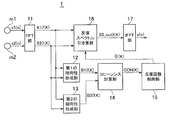
- the signal processing apparatus 1 includes a pair of microphones m1 and m2, a fast Fourier transform (FFT) 11, a first directivity forming unit 12, a second directivity forming unit 13, It has a coherence calculation unit 14, an iterative number control unit 15, an iterative spectrum subtraction unit 16, and an inverse fast Fourier transform (IFFT) unit 17.
- FFT fast Fourier transform
- IFFT inverse fast Fourier transform
- the pair of microphones m1 and m2 are arranged at a predetermined distance or an arbitrary distance, and each captures surrounding sounds. Audio signals (input signals) captured by the microphones m1 and m2 are converted into digital signals s1 (n) and s2 (n) via corresponding analog-digital (AD) converters (not shown), and the FFT unit 11 Given to.
- n is an index indicating the input order of samples on a time series, and is expressed as a positive integer. In the text, the smaller the value of n, the older the input sample, and the larger the value, the newer the input sample.
- the FFT unit 11 receives the input signal sequences s1 (n) and s2 (n) from the microphones m1 and m2, and performs fast Fourier transform (or discrete Fourier transform) on the input signals s1 and s2. Thereby, the input signals s1 and s2 can be expressed in the frequency domain.
- analysis frames FRAME1 (K) and FRAME2 (K) composed of predetermined N samples are configured from the input signals s1 (n) and s2 (n).
- An example in which the analysis frame FRAME1 (K) is configured from the input signal s1 (n) is shown in the following equation (1), and the analysis frame FRAME2 (K) is the same.
- N is the number of samples and is a positive integer.
- K is an index indicating the order of frames and is expressed as a positive integer.
- the index representing the latest analysis frame to be analyzed is K unless otherwise specified.
- the FFT unit 11 converts the frequency domain signals X1 (f, K) and X2 (f, K) into the frequency domain signals X1 (f, K) by performing a fast Fourier transform process for each analysis frame. And X2 (f, K) are supplied to the iterative coherence filter processing unit 12, respectively.
- f is an index representing frequency.
- X1 (f, K) is not a single value but is composed of spectral components of a plurality of frequencies f1 to fm as shown in equation (2).
- X1 (f, K) is a complex number and consists of a real part and an imaginary part. The same applies to X2 (f, K) and B1 (f, K) and B2 (f, K) described later.
- X1 (f, K) ⁇ X1 (f1, K), X1 (f2, K), ..., X1 (fm, k) ⁇ (2)
- the iterative spectrum subtraction unit 16 repeatedly executes the spectrum subtraction process for the number of iterations ⁇ (k) given from the iteration number control unit 15 to obtain a signal SS_out (f, K) in which the noise component is suppressed, and an IFFT unit Give to 17.
- the IFFT unit 17 performs inverse fast Fourier transform on the noise-suppressed signal SS_out (f, K) to obtain an output signal y (n) that is a time domain signal.
- the signal processing apparatus 1 includes a first directivity forming unit 12, a second directivity forming unit 13, a coherence calculation unit 14, an iteration number control unit 15, and an iterative spectrum subtraction unit 16.
- the iteration count control unit 15 gives the iteration spectrum subtraction unit 16 information on the iteration count ⁇ (k).
- the number of iterations of the iterative spectrum subtraction process is controlled according to the arrival direction of the disturbing speech, and both the naturalness of the speech and the noise suppression performance are realized.
- Coherence is applied as a feature value that reflects the arrival direction of jamming speech.
- the first directivity forming unit 12 is a signal B1 (f having strong directivity in a specific direction with respect to the sound source direction (S, FIG. 2A) from the frequency domain signals X1 (f, K) and X2 (f, K). , K).
- the second directivity forming unit 13 forms a signal B2 (f, K) having high directivity in the other specific direction of the sound source direction from the frequency domain signals X1 (f, K) and X2 (f, K). Is.
- Existing methods can be applied to form signals B1 (f, K) and B2 (f, K) that have strong directivity in each specific direction.
- S is the sampling frequency
- N is the FFT analysis frame length
- ⁇ is the difference in sound wave arrival time between microphones
- i is the imaginary unit
- f is the frequency.
- the microphone arrays m1 and m2 have directivity characteristics as shown in FIG. 2B.
- the calculation is performed in the time domain, but the same can be said even if it is performed in the frequency domain.
- the equations in this case are the above-described equations (3) and (4).
- the arrival direction ⁇ is ⁇ 90 degrees. That is, the directivity signal b1 (f) from the first directivity forming unit 12 has strong directivity in the right direction (R) as shown in FIG.
- the directivity signal B2 (f) has a strong directivity in the left direction (L) as shown in FIG. 3B.
- F indicates the forward direction and B indicates the backward direction.
- ⁇ ⁇ 90 degrees, but ⁇ is not limited to ⁇ 90 degrees.
- the coherence calculation unit 14 performs the operations shown in the equations (6) and (7) on the directional signals b1 (f, K) and B2 (f, K) obtained as described above, thereby performing coherence.
- COH (K) is obtained.
- B2 (f) * in the equation (6) is a conjugate complex number of B2 (f).
- the frame index K is omitted because it is not involved in the calculations shown in the equations (6) and (7).
- equation (6) is an equation for calculating the correlation for a certain frequency component
- equation (7) is calculating the average of the correlation values of all frequency components. Therefore, the case where the coherence COH is small is a case where the correlation between the two directivity signals B1 and B2 is small, and conversely, the case where the coherence COH is large can be paraphrased as a case where the correlation is large.
- the input signal when the correlation is small can be said to be a signal whose input arrival direction is greatly deviated to either the right or left, that is, the signal coming from other than the front.
- the range that the coherence value takes varies depending on the case where the arrival direction is near the front a, the middle b between the front and the side, and the side c.
- the arrival direction of disturbing speech was estimated, and the number of iterations of the iterative spectrum subtraction process was controlled based on the result.
- the iteration number control unit 15 obtains the iteration number ⁇ (K) determined by the range of the coherence COH (K) calculated by the coherence calculation unit 14 and gives it to the iteration spectrum subtraction unit 16. .
- FIG. 5 shows an example of the iterative spectrum subtraction unit 16, in which the spectrum subtraction process is executed for the number of iterations ⁇ (K) given from the iteration number control unit 15.
- ⁇ K
- any existing configuration such as a configuration for executing a conventional spectrum subtraction process or a configuration for repeating the spectrum subtraction processing may be applied.
- the iterative spectrum subtraction unit 16 includes an input signal / repetition number receiving unit 21, a repetition number counter / subtracted signal initialization unit 22, a third directivity forming unit 23, a spectrum subtraction processing unit 24, and a repetition number counter.
- An update / repetition execution availability control unit 25, a subtracted signal update unit 26, and a signal transmission unit 27 after spectrum subtraction processing are included.
- these units 21 to 27 operate in cooperation to execute processing shown in a flowchart of FIG. 9 to be described later.
- the input signal / iteration number receiving unit 21 includes frequency domain signals X1 (f, K) and X2 (f, K) output from the FFT unit 11, and the number of iterations ⁇ (K) output from the iteration number control unit 15. And receive.
- the iterative number counter / subtracted signal initialization unit 22 includes a counter variable (hereinafter referred to as an iterative number counter) p representing the number of iterations, and a subtracted signal tmp_1ch (f) that is a signal to which a noise signal is subtracted in the spectral subtraction process.
- K, p) and tmp_2ch (f, K, p) are initialized.
- the initialization value of the iteration counter p is 0, and the initialization values of the subtracted signals tmp_1ch (f, K, p) and tmp_2ch (f, K, p) are X1 (f, K) and X2 (f, respectively. , K).
- the third directivity forming unit 23 Based on the subtracted signals tmp_1ch (f, K, p) and tmp_2ch (f, K, p) at the current number of iterations, the third directivity forming unit 23 performs a noise signal (third Directivity signal) N (f, K, p) is formed.
- the noise signal N (f, K, p) changes depending on the number of iterations.
- the initialization values of the subtracted signals tmp_1ch (f, K, p) and tmp_2ch (f, K, p) are X1 (f, K) and X2 (f, K), respectively.
- the noise signal N (f, K, p) has the directivity shown in FIG. That is, the noise signal N (f, K, p) has directivity having a blind spot in the front direction.
- the spectrum subtraction processing unit 24 (9 ) And (10), spectrum subtraction processing at the current number of iterations is performed to form spectral subtraction signals SS_1ch (f, K, p) and SS_2ch (f, K, p).
- the iteration number counter update / iteration execution enable / disable control unit 25 increments the iteration number counter p by 1 when the spectrum subtraction process at the current iteration number is completed, and then the iteration number counter p is output from the iteration number control unit 15. It is determined whether the number of iterations ⁇ (K) has been reached, and if not reached, each part is controlled to continue the spectrum subtraction process, and if it has been reached, the iteration of the spectrum subtraction process is terminated. Control each part.
- the subtracted signal update unit 26 when continuing the subtraction of the spectrum subtraction process, subtracts the subtracted signals tmp_1ch (f, K, p) and tmp_2ch (f, K, p), respectively, at the previous iteration count.
- the post-processing signals SS_1ch (f, K, p-1) and SS_2ch (f, K, p-1) are updated.
- the spectral subtraction processing signals SS_1ch (f, K, p) and SS_2ch (f, K, p) obtained at that time are obtained.
- the signal transmission unit 27 after the spectrum subtraction process increases the variable K that defines the frame by 1, and starts processing of the next frame.
- the iteration count control unit 15 includes a coherence reception unit 31, an iteration count collation unit 32, an iteration count storage unit 33, and an iteration count transmission unit 34.
- the coherence receiving unit 31 takes in the coherence COH (K) output from the coherence calculating unit 14.
- the iteration number matching unit 32 extracts the iteration number ⁇ (K) of the iteration spectrum subtraction process from the iteration number storage unit 33 using the coherence COH (K) as a key.
- the iteration count storage unit 33 stores the iteration count ⁇ (K) in association with the range of the coherence COH, as shown in FIG.
- the coherence COH is greater than A and less than or equal to B
- the number of iterations ⁇ is associated
- the coherence COH is greater than B and less than or equal to C
- the number of iterations ⁇ ( ⁇ ⁇ ) is associated.
- COH is greater than C and less than or equal to D
- an example is shown in which the number of iterations ⁇ ( ⁇ ⁇ ) is associated.
- the iteration number transmission unit 34 gives the iteration number ⁇ (K) obtained by the iteration number verification unit 32 to the iteration spectrum subtraction unit 16.
- the signals s1 (n) and s2 (n) input from the pair of microphones m1 and m2 are respectively converted from time domain to frequency domain signals X1 (f, K) and X2 (f, K) by the FFT unit 11. After that, the first and second directivity forming units 12 and 13 and the repetitive spectrum subtracting unit 16 are provided.
- the first and second directivity forming units 12 and 13 respectively have first and second blind spots in a predetermined direction.
- Directional signals B1 (f, K) and B2 (f, K) are generated.
- the coherence calculation unit 14 applies the first and second directivity signals B1 (f, K) and B2 (f, K), and executes the calculations of the expressions (6) and (7).
- the coherence COH (K) is calculated, and the iteration count control unit 15 extracts the iteration count ⁇ (K) corresponding to the range to which the calculated coherence COH (K) belongs and provides it to the iteration spectrum subtraction unit 16.
- the spectrum subtraction process with the frequency domain signals X1 (f, K) and X2 (f, K) as the initial subtracted signals is repeatedly executed by the number of iterations ⁇ (K).
- the signal SS_out (f, K) after the repeated spectral subtraction is supplied to the IFFT unit 17.
- the signal SS_out (f, K) after repetitive spectrum subtraction which is a frequency domain signal, is converted into a time domain signal y (n) by inverse fast Fourier transform, and this time domain signal y (n) is Is output.
- FIG. 9 shows the processing of a certain frame, and the processing shown in FIG. 9 is repeated for each frame.
- the iteration count counter p is set to 0 and subtracted Signals tmp_1ch (f, K, p) and tmp_2ch (f, K, p) are initialized to frequency domain signals X1 (f, K) and X2 (f, K), respectively (step S1).
- Step S2 based on the subtracted signals tmp_1ch (f, K, p) and tmp_2ch (f, K, p) at the current number of iterations, a noise signal N (f, K, p) is formed according to equation (8).
- Step S5 After the iteration number counter p is incremented by 1 (step S4), it is determined whether or not the updated iteration number counter p is smaller than the iteration number ⁇ (K) output from the iteration number control unit 15. (Step S5).
- the subtracted signals tmp_1ch (f, K, p) and tmp_2ch (f, K, p) are After the spectrum subtraction processing signal SS_1ch (f, K, p-1) and SS_2ch (f, K, p-1) are updated to SS_2ch (f, K, p-1), respectively, at the previous iteration number (step S6), the process proceeds to step S2 described above. To do.
- Step S7 the process proceeds to the next frame.
- the number of iterations of the iterative spectrum subtraction process is adaptively determined according to the direction of arrival of the disturbing speech, and the iterative spectrum subtraction process is executed for the number of iterations. Can be realized in a well-balanced manner.
- the signal processing device of the first embodiment to a communication device such as a video conference system, a mobile phone, or a smartphone, it is possible to expect improvement in call sound quality.
- the signal processing apparatus and method of the second embodiment are also characterized in that the number of repetitions of the spectral subtraction process is repeated and adaptively controlled, and the behavior of parameters used for the control is the first implementation. It is different from the example.
- the number of iterations of the spectral subtraction process is fixed.
- the optimum number of iterations depends on the noise characteristics. Therefore, if the number of iterations is fixed, there is a risk that the amount of noise suppression will be insufficient, and the speech may be distorted each time the iterations are repeated. Occurs. Therefore, in the second embodiment, it is intended to set an optimum number of repetitions so that the naturalness of sound quality with less distortion and musical noise and the suppression performance are realized in a balanced manner.
- the behavior of the coherence COH (K, p) is used to determine the end of the iteration, and the reason for the use will be described below.
- the coherence filter coefficient coef (f, K, p) for calculating the coherence COH (K, p) by performing the averaging process as shown in the equation (7) has a blind spot on the left and right as shown in the equation (6). Since it is also a cross-correlation of signal components, when the correlation is large, it is a voice component arriving from the front with no bias in the arrival direction, and when the correlation is small, it is a component whose arrival direction is biased to the right or left. Thus, it is also associated with the incoming direction of the input voice.
- the coherence filter coefficient coef (f, K, p) is averaged over all the number of peripheral components, and the coherence COH (K, p) is calculated according to Equations (6) and (7) to confirm the behavior. Then, it can be confirmed that as the number of iterations increases, the coherence COH (K, p) in the noise interval increases, and the contribution of components coming from the side decreases.
- the number of iterations at which coherence COH (K, p) takes a maximum value is considered to be the number of times that the suppression performance and sound quality are balanced. It is done.
- the coherence COH (K, p) for each iteration is observed, and the iterative process is terminated when the change (behavior) of the coherence COH (K, p) starts to decrease. It was.
- the iterative spectrum subtraction process can be executed with the optimum number of iterations.
- FIG. 10 shows the configuration of the signal processing apparatus according to the second embodiment, and the same or corresponding parts as those in FIG. 1 according to the first embodiment are denoted by the same reference numerals.
- the signal processing apparatus 1A includes a pair of microphones m1 and m2, an FFT unit 11, a first directivity forming unit 12, a second directivity forming unit 13, a coherence calculation unit 14, and an iteration count control unit.
- the first embodiment is different from the first embodiment in that it has 15A, an iterative spectrum subtraction unit 16A and an IFFT unit 17, and has an iterative number control unit 15A and an iterative spectrum subtraction unit 16A.
- the subtracted signals tmp_1ch (f, K, p) and tmp_2ch (f, K, p) at each number of iterations form the first and second directivities, respectively.
- the repetition end flag FLG (K, p) output from the iteration number control unit 15A is fetched and the current iteration is performed when the iteration end flag FLG (K, p) is off.
- the spectrum subtraction process is executed at the number of times p, and the iterative spectrum subtraction process is terminated without executing the spectrum subtraction process at the current number of iterations p when the iteration end flag FLG (K, p) is on.
- the first directivity forming unit 12 and the second directivity forming unit 13 have subtracted signals tmp_1ch (f, K, p) and tmp_2ch ( f, K, p) is input, and the input signal is subjected to the same calculation as in the first embodiment, and the directivity signals B1 (f, K, p), B2 (f, K, p) Form.
- the iteration number control unit 15A of the second embodiment determines whether the change in the coherence COH (K, p) given from the coherence calculation unit 14 has changed from an increase to a decrease.
- An iterative end flag FLG (K, p) that turns on when it turns is supplied to the iterative spectrum subtraction unit 16A.
- FIG. 11 The detailed configuration of the iterative spectrum subtraction unit 16A according to the second embodiment is shown in FIG. 11, and the same or corresponding parts as those in FIG. 5 according to the first embodiment are denoted by the same reference numerals.
- the iterative spectrum subtracting unit 16A includes an input signal receiving unit 21A, an iterative number counter / subtracted signal initialization unit 22, a subtracted signal transmission / repetition end flag receiving unit 28, an iterative execution permission control / an iterative number counter updating unit 25A, 3 directivity forming unit 23, spectrum subtraction processing unit 24, subtracted signal update unit 26, and spectrum subtraction-processed signal transmission unit 27.
- the input signal / repetition count receiving unit 21A receives the frequency domain signals X1 (f, K) and X2 (f, K) output from the FFT unit 11.
- the subtracted signal transmission / repetition end flag receiving unit 28 receives the subtracted signals tmp_1ch (f, K, p) and tmp_2ch (f, K, p) at the current number of iterations as the first directivity forming unit 12 and the second directivity forming unit 12, respectively. And the repetition end flag FLG (K, p) transmitted by the repetition number control unit 15A are received.
- the iterative execution enable / disable control / iteration count counter updating unit 25A determines whether the received iteration end flag FLG (K, p) is on or off. If the iteration end flag FLG (K, p) is off, spectrum subtraction is performed. Each unit is controlled so as to continue the process iteration, and when the iteration end flag FLG (K, p) is on, each unit is controlled so as to end the iteration of the spectrum subtraction process. Further, the repeatability control / repetition count counter updating unit 25A increments the repeat count counter p by 1 when the repetition end flag FLG (K, p) is off.
- the third directivity forming unit 23 the spectrum subtraction processing unit 24, the subtracted signal update unit 26, and the post-spectrum subtraction signal transmission unit 27 are the same as those in the first embodiment, description thereof is omitted.
- FIG. 12 shows a detailed configuration of the iteration number control unit 15A according to the second embodiment.
- the iteration count control unit 15A includes a coherence reception unit 31, a coherence behavior determination unit 32A, a previous coherence storage unit 33A, and an iteration end flag transmission unit 34A.
- the coherence receiving unit 31 takes in the coherence COH (K, p) output from the coherence calculating unit 14 as in the first embodiment.
- the coherence behavior determination unit 32A determines the coherence from the received coherence COH (K, p) of the current iteration and the previous iteration of coherence COH (K, p-1) stored in the previous coherence storage unit 33A. , The iteration end flag FLG (K, p) is formed, and then the coherence COH (K, p) of the current iteration is stored in the previous coherence storage unit 33A.
- the coherence behavior determination unit 32A turns off the iteration end flag FLG (K, p) when the coherence COH (K, p) of the current iteration is greater than the coherence COH (K, p-1) of the previous iteration.
- the coherence COH (K, p) of the current iteration is less than or equal to the coherence COH (K, p-1) of the previous iteration
- the iteration end flag FLG (K, p) is turned on.
- the previous coherence storage unit 33A stores the coherence COH (K, p-1) in the previous iteration.
- the iterative end flag transmitting unit 34A gives the iterative end flag FLG (K, p) of the current iteration formed by the coherence behavior determining unit 32A to the iterative spectrum subtracting unit 16A.
- Signals s1 (n) and s2 (n) input from the pair of microphones m1 and m2 are converted from time domain to frequency domain signals X1 (f, K) and X2 (f, K) by the FFT unit 11, respectively.
- To the iterative spectrum subtraction unit 16A To the iterative spectrum subtraction unit 16A.
- subtracted signals tmp_1ch (f, K, p) and tmp_2ch (f, K, p) at the number of iterations are formed, and these subtracted signals tmp_1ch (f, K, p) and tmp_2ch (f, K, p) are given to the corresponding first or second directivity forming unit 12 or 13.
- the first and second directivity forming units 12 and 13 each have a blind spot in a predetermined direction.
- second directional signals B1 (f, K, p) and B2 (f, K, p) are generated.
- the first and second directivity signals B1 (f, K, p) and B2 (f, K, p) are applied, and the equations (6) and (7)
- the calculation is performed to calculate the coherence COH (K, p)
- the iteration number control unit 15A calculates the coherence COH (K, p) of the calculated current iteration number and the coherence COH (K , p-1) and the iteration end flag FLG (K, p) is formed and provided to the iteration spectrum subtraction unit 16A.
- the spectrum subtraction process using the frequency domain signals X1 (f, K) and X2 (f, K) as the initial subtracted signals is turned on when the iteration end flag FLG (K, p) is turned on.
- the signal is repeatedly executed up to a certain number of iterations, and the obtained signal after repetitive spectrum subtraction SS_out (f, K) is given to the IFFT unit 17.
- the signal SS_out (f, K) after repetitive spectrum subtraction which is a frequency domain signal, is converted into a time domain signal y (n) by inverse fast Fourier transform, and this time domain signal y (n) is Is output.
- FIG. 13 shows the processing of a certain frame, and the processing shown in FIG. 13 is repeated for each frame.
- FIG. 13 the same steps as those in FIG. 9 according to the first embodiment are denoted by the same reference numerals.
- the iterative spectrum subtraction unit 16A p is reset to 0, and the subtracted signals tmp_1ch (f, K, p) and tmp_2ch (f, K, p) are initialized to frequency domain signals X1 (f, K) and X2 (f, K), respectively (step S1).
- the iterative spectrum subtraction unit 16A converts the subtraction signals tmp_1ch (f, K, p) and tmp_2ch (f, K, p) of the current number of iterations into the first directivity forming unit 12 and the second directivity, respectively. It transmits to the formation part 13 (step S8), and receives the repetition end flag FLG (K, p) formed and transmitted accordingly (step S9).
- the iterative spectrum subtraction unit 16A determines whether or not the received iterative end flag FLG (K, p) is on (step S10).
- the iteration spectrum subtraction unit 16A adds the subtracted signals tmp_1ch (f, K, p) and tmp_2ch (f, K, p) in the current iteration. Based on the equation (8), a noise signal N (f, K, p) is formed (step S2), and the subtracted signals tmp_1ch (f, K, p) and tmp_2ch (f, K) in the current iteration are further generated.
- the spectrum subtraction process in the current iteration is executed according to the equations (9) and (10), and the signal SS_1ch (f , K, p) and SS_2ch (f, K, p) are formed (step S3).
- the iterative spectrum subtraction unit 16A increments the iteration number counter p by 1 (step S4), and then subtracts the subtracted signals tmp_1ch (f, K, p) and tmp_2ch (f, K, p) respectively.
- the process proceeds to step S8 described above.
- the iterative spectrum subtraction unit 16A performs the spectral subtraction signal SS_1ch (f, K, p-1) or SS_2ch (f, K, p-1) is given to the IFFT unit 17 as a signal SS_out (f, K) after iterative spectral subtraction, and the parameter K defining the frame is incremented by 1.
- Step S7 the process for the current frame is terminated, and the process proceeds to the process for the next frame.
- the end timing of the repeated iteration of the iterative spectrum subtraction process is captured according to the direction of arrival of the target speech, and the iterative spectrum subtraction process is executed until the end timing is reached. And suppression performance can be realized in a well-balanced manner.
- the signal processing device of the second embodiment to a communication device such as a video conference system, a mobile phone, or a smartphone, it is possible to expect improvement in call sound quality.
- the spectrum subtraction process is not limited to that described in the above embodiment.
- many are known as spectral subtraction processes.
- the noise signal N (f, K, p) may be multiplied by a subtraction coefficient and then the subtraction process may be performed.
- the signal SS_out (f, K) after iterative spectrum subtraction may be subjected to a flooring process and then given to the IFFT unit 17.
- the coherence COH (K) is used to set the same repetition times for all frequency components. However, different repetition times may be set for each frequency. In this case, for example, instead of the coherence COH (K), the iteration times may be determined using the correlation value coef (f) for each frequency component obtained by the equation (6).
- the number of iterations is decreased as the coherence COH (K) is larger.
- the coherence COH (K) is larger. It may be configured to increase the number of repetitions.
- the coherence range and the number of iterations are associated in advance, and the iteration times associated with the range to which the current coherence belongs are used as the iteration times in the iterative spectrum subtraction process.
- the relationship between coherence and iteration times may be functionalized in advance, and the iteration times in the iterative spectrum subtraction process may be determined by function calculation using the current coherence as an input.
- the coherence behavior at the current iteration count is less than or equal to the coherence at the previous iteration count, so that the coherence behavior at each iteration count has changed from increasing to decreasing. It is determined that the coherence behavior has changed from increasing to decreasing when the coherence at the current number of iterations is less than or equal to the coherence at the previous number of iterations for a predetermined number of times, for example, twice. You may do it.
- the repetitive times are controlled in order to balance the suppression performance and the sound quality.
- the sound performance is lowered by focusing on the suppression performance, and conversely, the suppression performance is conserved by focusing on the sound quality.
- the output signal may be a signal after the spectrum subtraction process in a predetermined number of iterations before the number of iterations in which the coherence starts to decrease.
- the relationship between the coherence range described in the conversion table and the repetition times is determined so that the sound quality is lowered with emphasis on the suppression performance, and conversely, the sound quality is emphasized.
- the suppression performance may be set to be conservative.
- the end of the iterative process is determined based on the level of coherence at successive iterations, but the coherence slope (differential coefficient) at successive iterations is shown. Based on this, the end of the iterative process may be determined.
- the slope changes to a value within the range of 0 or 0 ⁇ ⁇ ( ⁇ is a value that is small enough to determine the maximum value)
- ⁇ is a value that is small enough to determine the maximum value
- the slope can be calculated as the difference in coherence between successive iterations if the time difference between the coherence calculation times at the successive iterations is constant. If the time difference between the calculation times is not constant, the time can be recorded every time the coherence is calculated, and the difference in coherence between successive iterations can be calculated by dividing by the time difference.
- the coherence that is the average of the coherence filter coefficients (coef (f) that is the correlation value for each frequency component) is used to determine the end of the iterative process. If the statistic represents the representative value of the distribution of the coefficients coef (0, K, p) to coef (M-1, K, p), another statistic such as the median is applied instead of the coherence. May be.
- the one using the coherence COH (K) is shown for determining whether the iterative process is continued or ended.
- the coherence COH (K) the “content of the target voice in the input voice signal” is used. It may be possible to determine whether to continue or end the iterative process using another feature amount having the concept of “.”
- the processing that has been processed with the frequency domain signal may be performed with the time domain signal if possible.
- the audio signal to be processed of the present invention is not limited to this.
- the present invention can be applied to processing a pair of audio signals read from a recording medium, and the present invention can be applied to processing a pair of audio signals transmitted from the opposite device. Can be applied.
- the signal may already be a frequency domain signal when it is input to the signal processing device.
Landscapes
- Engineering & Computer Science (AREA)
- Physics & Mathematics (AREA)
- Computational Linguistics (AREA)
- Signal Processing (AREA)
- Health & Medical Sciences (AREA)
- Audiology, Speech & Language Pathology (AREA)
- Human Computer Interaction (AREA)
- Acoustics & Sound (AREA)
- Multimedia (AREA)
- Quality & Reliability (AREA)
- Spectroscopy & Molecular Physics (AREA)
- Circuit For Audible Band Transducer (AREA)
Abstract
信号処理装置は、入力音声信号に含まれている雑音成分を反復スペクトル引き算処理によって抑制する。本装置は、一対の入力音声信号に基づいて指向性特性を有した第1および第2の指向性信号からコヒーレンスを得て、このコヒーレンスに基づいてスペクトル引き算処理の反復回数を制御することにより、入力音声信号に含まれている雑音成分を抑制する。
Description
本発明は信号処理装置および方法に関し、たとえば、電話機やテレビ会議装置などの音響信号を含む音声信号を扱う通信機や通信方法に関する。
取得した音声信号中に含まれる雑音成分を抑圧する手法の一つとして、スペクトル引き算法が挙げられる。これは、スペクトル減算法、周波数減算法または周波数引き算法とも呼ばれ、雑音を含む音声信号のスペクトルから雑音スペクトルを減算する。
しかし、スペクトル引き算処理は、雑音成分を抑圧する効果がある一方で、ミュージカルノイズという異音成分(トーン性の雑音)を発生させてしまう。
緒方伸哉、他「反復スペクトル引き算法によるミュージカルノイズの低減」、日本音響学会講演論文集、第387-388頁、2001年3月に記載されているように、スペクトル引き算処理によって雑音成分が抑圧された信号に対して、再びスペクトル引き算処理を行い、この反復処理を所定回数、たとえばここでは10回繰り返すことにより発生するミュージカルノイズを含む雑音を抑圧する。
従来の反復スペクトル引き算法の場合、特に指向性を形成して雑音信号を推定する場合、推定した雑音成分を過剰に引き算しすぎてしまうことがある。これは目的話者以外の人の音声、すなわち妨害音声の到来方位が、形成される指向性の方位と一致する場合には、推定した雑音信号の精度が高いため、一度の引き算で大きな抑圧効果が得られる。このような場合には、反復回は少なくてもよいのにもかかわらず、固定の反復回を適用すると、反復回が多すぎて必要以上に引き算してしまうためであり、その結果、目的音声成分まで抑圧され、音声に歪みが生じてしまう。
一方、妨害音声の到来方位が、形成した指向性方位から逸れている場合には、推定した雑音成分の精度が低くなり、そのため、一度の引き算での抑圧効果は小さく、反復回が多いことが好ましい。しかし、反復回が固定されていると、実際の反復回が所望する反復回より少なくなり、目的音声への影響は小さいものの、雑音成分の抑圧性能が不足する。
以上のように、反復スペクトル引き算法は、反復を繰り返すたびに音声成分が歪んで自然さが損なわれるうえ、妨害音声の到来方位によって最適な反復回は変動するという問題があった。
本発明は、反復スペクトル引き算法に従って雑音成分を抑圧し、かつ音質の自然さとミュージカルノイズを含む雑音の抑圧性能とがバランス良く実現できる信号処理装置および方法を提供することを目的とする。
本発明の信号処理装置は、雑音成分を含む入力信号を繰り返してスペクトル引き算処理する反復スペクトル引き算部を含み、このスペクトル引き算処理の繰返しによって雑音成分を抑制し、入力信号から目的信号の含有量を特徴量として算出する特徴量算出部と、この特徴量に基づきスペクトル引き算処理の反復回数を制御する反復回数制御部とを含んで構成される。
また、本発明の信号処理方法は、雑音成分を含む入力信号を繰り返してスペクトル引き算処理する反復スペクトル引き算工程を含み、このスペクトル引き算処理の繰り返しによって雑音成分を抑制し、入力信号から目的信号の含有量を特徴量として算出する特徴量算出工程と、この特徴量に基づきスペクトル引き算処理の反復回数を制御する反復回数制御工程とを含む。
また、本発明は、コンピュータを上述の信号処理装置として機能させるコンピュータプログラムとしても実現される。
このように本発明によれば、反復スペクトル引き算法に従って雑音成分を抑圧しても、音質の自然さとミュージカルノイズを含む雑音の抑圧性能とをバランス良く実現できる信号処理装置および方法が提供される。
本発明の目的と特徴は、以下の添付図面を参照した詳細な説明を考慮することで、さらに明らかになる。
本発明の実施例による信号処理装置の構成を示すブロック図である。
および
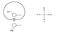
図1に示す実施例における第1および第2の指向性形成部からの指向性信号の特性を示す説明図である。
および
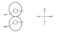
図1に示す実施例における第1および第2の指向性形成部による指向性信号を示す説明図である。
到来方位ごとのコヒーレンスの挙動を示す説明図である。
図1に示す実施例における反復スペクトル引き算部の詳細構成を示すブロック図である。
同実施例の反復スペクトル引き算部における第3の指向性形成部の出力信号の指向性の説明図である。
同実施例における反復回数制御部の詳細構成を示すブロック図である。
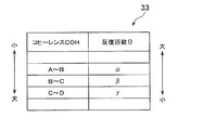
同実施例の反復回数制御部における反復回数記憶部の記憶内容の説明図である。
同実施例の反復スペクトル引き算部における詳細動作を示すフローチャートである。
本発明の第2の実施例における信号処理装置の構成を示すブロック図である。
図10に示す実施例における反復スペクトル引き算部の詳細構成を示すブロック図である。
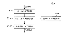
同実施例における反復回数制御部の詳細構成を示すブロック図である。
同実施例の反復スペクトル引き算部における詳細動作を示すフローチャートである。
次に添付図面を参照にして、スペクトル引き算処理を反復して繰り返す反復回を適応的に制御することを特徴とする本発明の、第1の実施例に係る信号処理装置について詳細に説明する。
第1の実施例の信号処理装置は、妨害音声の到来方位に応じて、反復スペクトル引き算処理の反復回を制御し、音声の自然さと雑音の抑圧性能の双方を実現する。
図1は本実施例の信号処理装置の機能を示しており、これらの機能はハードウェアで構成実現してもよい。また、一対のマイクm1およびm2以外は、コンピュータなどの処理システムに含まれる中央処理装置(CPU)が実行するソフトウェア、たとえば信号処理プログラムで実現することも可能である。その場合、図面にブロックの形で示されている各機能部は、回路や装置として表現されていても、実体は、CPUで実行されるプログラムであることがある。このようなプログラムは、記録媒体に記録されて、コンピュータに読み込まれ、実行される。
図1に示すように、信号処理装置1は、一対のマイクm1およびm2と、高速フーリエ変換(FFT)11と、第1の指向性形成部12と、第2の指向性形成部13と、コヒーレンス計算部14と、反復回数制御部15と、反復スペクトル引き算部16、および逆高速フーリエ変換(IFFT)部17とを有する。
一対のマイクm1およびm2は、所定距離もしくは任意の距離を離して配置され、それぞれ周囲の音声を捕捉する。各マイクm1およびm2で捕捉された音声信号(入力信号)は、図示しない対応するアナログ-デジタル(AD)変換器を介してデジタル信号s1(n)、s2(n)に変換されてFFT部11に与えられる。なお、nは時系列上でサンプルの入力順を表すインデックスであり、正の整数で表現される。本文中では、nの値が小さいほど古い入力サンプルであり、大きいほど新しい入力サンプルである。
FFT部11は、マイクm1およびm2から入力信号系列s1(n)およびs2(n)を受け取り、その入力信号s1およびs2に高速フーリエ変換(あるいは離散フーリエ変換)を行う。これにより、入力信号s1およびs2を周波数領域で表現することができる。なお、高速フーリエ変換を実施するにあたり、入力信号s1(n)およびs2(n)から、所定のN個のサンプルからなる分析フレームFRAME1(K)およびFRAME2(K)を構成する。入力信号s1(n)から分析フレームFRAME1(K)を構成する例を以下の(1)式に示すが、分析フレームFRAME2(K)も同様である。Nはサンプル数であり、正の整数である。

なお、Kはフレームの順番を表すインデックスであり、正の整数で表現される。本文中では、Kの値が小さいほど古い分析フレームであり、大きいほど新しい分析フレームである。また、以降の説明において、特に但し書きがない限りは、分析対象となる最新の分析フレームを表すインデックスはKである。
FFT部11は、分析フレームごとに高速フーリエ変換処理を施すことで、周波数領域信号X1(f,K)およびX2(f,K)に変換し、得られた周波数領域信号X1(f,K)およびX2(f,K)をそれぞれ、反復コヒーレンスフィルタ処理部12に与える。
なお、fは周波数を表すインデックスである。また、X1(f,K)は単一の値ではなく(2)式に示すように、複数の周波数f1~fmのスペクトル成分から構成されるものである。さらに、X1(f,K)は複素数であり、実部と虚部からなる。X2(f,K)や後述するB1(f,K)およびB2(f,K)も同様である。
X1(f,K)={X1(f1,K),X1(f2,K),…,X1(fm,k)} ・・・(2)
X1(f,K)={X1(f1,K),X1(f2,K),…,X1(fm,k)} ・・・(2)
反復スペクトル引き算部16は、スペクトル引き算処理を反復回数制御部15から与えられた反復回数Θ(k)だけ繰り返し実行し、雑音成分が抑圧された信号SS_out(f,K)を得て、IFFT部17に与える。
IFFT部17は、雑音抑圧後信号SS_out(f,K)に対して、逆高速フーリエ変換を施して時間領域信号である出力信号y(n)を得る。
図1に示すように、信号処理装置1は、第1の指向性形成部12、第2の指向性形成部13、コヒーレンス計算部14および反復回数制御部15、反復スペクトル引き算部16を有し、反復回数制御部15は反復スペクトル引き算部16に反復回数Θ(k)の情報を与える。上述したように、実施例の信号処理装置1では、妨害音声の到来方位に応じて、反復スペクトル引き算処理の反復回数を制御し、音声の自然さと雑音の抑圧性能の双方を実現しようとしており、妨害音声の到来方位を反映した特徴量としてコヒーレンスを適用する。
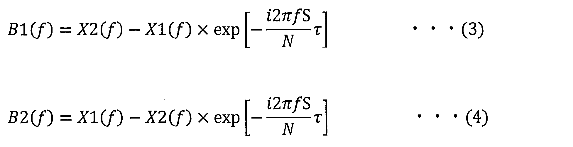
第1の指向性形成部12は、周波数領域信号X1(f,K)およびX2(f,K)から音源方向(S、図2A)に対して特定の方向に指向性が強い信号B1(f,K)を形成するものである。第2の指向性形成部13は、周波数領域信号X1(f,K) およびX2(f,K)から音源方向の他の特定の方向に指向性が強い信号B2(f,K)を形成するものである。それぞれの特定方向に指向性が強い信号B1(f,K)、B2(f,K)の形成方法としては既存の方法を適用でき、たとえば、(3)式を適用して右方向に指向性が強いB1(f,K)や(4)式を適用して左方向に指向性が強いB2(f,K)が形成できる。(3)式および(4)式では、フレームインデックスKは演算に関与しないので省略している。
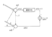
以下図2および図3を参照し、これらの式の意味を(3)式を例にして説明する。図2Aに示した方向θから音波が到来し、マイク間距離lだけ隔てて設置されている一対のマイクm1およびm2で捕捉されたとする。このとき、音波が一対のマイクm1およびm2に到達するまでには時間差が生じる。この到達時間差τは、音の経路差をdとすると、d=l×sinθなので、音速をcとすると(5)式で与えられる。
τ=l×sinθ/c ・・・(5)
τ=l×sinθ/c ・・・(5)
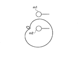
ところで、入力信号s1(n)にτだけ遅延を与えた信号s1(t-τ)は、入力信号s2(t)と同一の信号である。したがって、両者の差をとった信号y(n)=s2(t)-s1(t-τ)は、θ方向から到来した音が除去された信号となる。結果として、マイクロフォンアレーm1およびm2は図2Bのような指向特性を持つようになる。
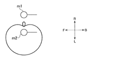
なお、以上では、時間領域で演算したが、周波数領域で行っても同様なことがいえる。この場合の式が、上述した(3)式および(4)式である。今、一例として、到来方位θが±90度であることを想定する。すなわち、第1の指向性形成部12からの指向性信号b1(f)は、図3Aに示すように右方向(R)に強い指向性を有し、第2の指向性形成部13からの指向性信号B2(f)は、図3Bに示すように左方向(L)に強い指向性を有する。なお、同図において、Fは前方向、またBは後方向を示す。以降は、θ=±90度であることを想定して説明するが、θは±90度に限定されるものではない。
コヒーレンス計算部14は、以上のようにして得られた指向性信号b1(f,K)、B2(f,K)に対し、(6)式および(7)式に示す演算を施すことでコヒーレンスCOH(K)を得るものである。(6)式におけるB2(f)*はB2(f)の共役複素数である。また、フレームインデックスKは、(6)式および(7)式に示す演算には関与しないので省略する。
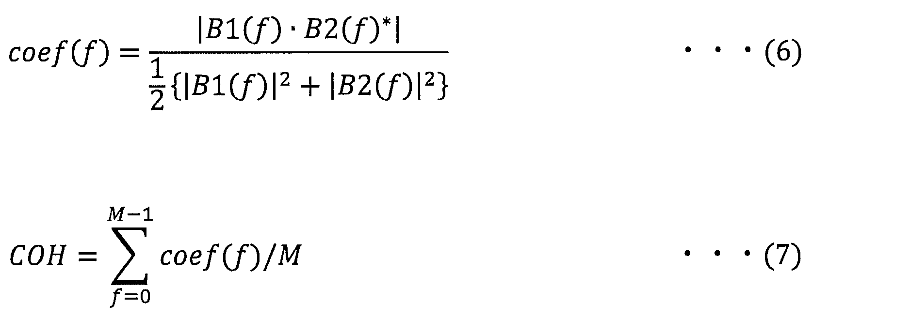
コヒーレンスの概念は、右から到来する信号と左から到来する信号の相関と言い換えられる。因みに(6)式はある周波数成分についての相関を算出する式であり、(7)式はすべての周波数成分の相関値の平均を計算している。したがって、コヒーレンスCOHが小さい場合とは、2つの指向性信号B1およびB2の相関が小さい場合であり、反対にコヒーレンスCOHが大きい場合とは相関が大きい場合と言い換えることができる。そして、相関が小さい場合の入力信号は、入力到来方位が右または左のどちらかに大きく偏っている、つまり、正面以外から到来している信号といえる。一方、コヒーレンスCOHの値が大きい場合は、到来方位の偏りがないため、入力信号が正面から到来する場合であるといえる。このようにコヒーレンスの大小で入力信号の到来方位が正面か否かを判定することができる。
図4に示すように、到来方位が正面寄りa、正面と側方の中間b、側方cのそれぞれの場合に応じて、コヒーレンスの値がとるレンジが変化していることが分かる。この性質を用いることで、妨害音声の到来方位を推定し、その結果に基づいて、反復スペクトル引き算処理の反復回数を制御することとした。
反復回数制御部15は、コヒーレンス計算部14が算出したコヒーレンスCOH(K)がどのような範囲内の値かによって定まる反復回数Θ(K)を得て、反復スペクトル引き算部16に与えるものである。
図5に反復スペクトル引き算部16の一例を示し、ここでは反復回数制御部15から与えられた反復回数Θ(K)だけスペクトル引き算処理を実行させる構成となっている。もちろん従来のスペクトル引き算処理の実行構成や、それを反復させるための構成等の既存のいかなる構成を適用しても構わない。
図5において、反復スペクトル引き算部16は、入力信号・反復回数受信部21、反復回数カウンタ・被減算信号初期化部22、第3の指向性形成部23、スペクトル引き算処理部24、反復回数カウンタ更新・反復実施可否制御部25、被減算信号更新部26およびスペクトル引き算処理後信号送信部27を有する。
反復スペクトル引き算部16においては、これらの各部21~27が協働して動作することにより、後述する図9のフローチャートに示す処理を実行する。
入力信号・反復回数受信部21は、FFT部11から出力された周波数領域信号X1(f,K)、X2(f,K)と、反復回数制御部15から出力された反復回数Θ(K)とを受け取る。
反復回数カウンタ・被減算信号初期化部22は、反復回数を表すカウンタ変数(以下、反復回数カウンタと呼ぶ)pと、スペクトル引き算処理において雑音信号が減算される信号である被減算信号tmp_1ch(f,K,p)、tmp_2ch(f,K,p)を初期化する。反復回数カウンタpの初期化値は0であり、被減算信号tmp_1ch(f,K,p)およびtmp_2ch(f,K,p)の初期化値はそれぞれ、X1(f,K)、X2(f,K)である。
第3の指向性形成部23は、現反復回数における被減算信号tmp_1ch(f,K,p)およびtmp_2ch(f,K,p)に基づいて、(8)式に従って、雑音信号(第3の指向性信号)N(f,K,p)を形成する。

雑音信号N(f,K,p)は反復回数によって変化するものである。被減算信号tmp_1ch(f,K,p)およびtmp_2ch(f,K,p)の初期化値がそれぞれX1(f,K)、X2(f,K)であって、これらの絶対値の差分をとって雑音信号N(f,K,p)を形成していることから理解できるように、雑音信号N(f,K,p)は、図6に示す指向性を有する。すなわち、雑音信号N(f,K,p)は、正面方位に死角を有する指向性を有する。
スペクトル引き算処理部24は、現反復回数における被減算信号tmp_1ch(f,K,p)およびtmp_2ch(f,K,p)と、雑音信号N(f,K,p)とに基づいて、(9)式および(10)式に従って、現反復回数におけるスペクトル引き算処理を行い、スペクトル引き算処理後信号SS_1ch(f,K,p)およびSS_2ch(f,K,p)を形成する。

反復回数カウンタ更新・反復実施可否制御部25は、現反復回数におけるスペクトル引き算処理が終了したときに、反復回数カウンタpを1インクリメントした後、反復回数カウンタpが反復回数制御部15から出力された反復回数Θ(K)に達したかを判定し、達しない場合にはスペクトル引き算処理の反復を継続するように各部を制御し、達した場合にはスペクトル引き算処理の反復繰り返しを終了するように各部を制御する。
被減算信号更新部26は、スペクトル引き算処理の反復を継続する場合に、被減算信号tmp_1ch(f,K,p)およびtmp_2ch(f,K,p)をそれぞれ、前回の反復回数でのスペクトル引き算処理後信号SS_1ch(f,K,p-1)およびSS_2ch(f,K,p-1)に更新する。
スペクトル引き算処理後信号送信部27は、スペクトル引き算処理の反復繰り返しを終了する場合に、その時点で得られているスペクトル引き算処理後信号SS_1ch(f,K,p)およびSS_2ch(f,K,p)の一方を、反復スペクトル引き算後信号SS_out(f,K)としてIFFT部17に与える。また、スペクトル引き算処理後信号送信部27は、フレームを規定する変数Kを1だけ増加させて次のフレームの処理を起動させる。
図7において、反復回数制御部15は、コヒーレンス受信部31、反復回数照合部32、反復回数記憶部33および反復回数送信部34を有する。
コヒーレンス受信部31は、コヒーレンス計算部14から出力されたコヒーレンスCOH(K)を取込む。
反復回数照合部32は、コヒーレンスCOH(K)をキーとして、反復回数記憶部33から、反復スペクトル引き算処理の反復回数Θ(K)を取り出す。
反復回数記憶部33は、図8に示すように、コヒーレンスCOHの範囲に対応付けて反復回数Θ(K)を記憶している。図8は、コヒーレンスCOHがAより大きくB以下の場合には反復回数αが対応付けられ、コヒーレンスCOHがBより大きくC以下の場合には反復回数β(β<α)が対応付けられ、コヒーレンスCOHがCより大きくD以下の場合には反復回数γ(γ<β)が対応付けられた例を示している。
反復回数送信部34は、反復回数照合部32が得た反復回数Θ(K)を反復スペクトル引き算部16に与えるものである。
次に、図面を参照し、第1の実施例の信号処理装置1の全体動作および反復スペクトル引き算部16における詳細動作について説明する。
一対のマイクm1およびm2から入力された信号s1(n)、s2(n)はそれぞれ、FFT部11によって時間領域から周波数領域の信号X1(f,K)、X2(f,K)に変換された後、第1および第2の指向性形成部12および13、反復スペクトル引き算部16に与えられる。
周波数領域の信号X1(f,K)およびX2(f,K)に基づき、第1および第2の指向性形成部12および13のそれぞれによって、所定の方位に死角を有する第1および第2の指向性信号B1(f,K)およびB2(f,K)が生成される。そして、コヒーレンス計算部14において、第1および第2の指向性信号B1(f,K)およびB2(f,K)を適用して、(6)式および(7)式の演算が実行され、コヒーレンスCOH(K)が算出され、反復回数制御部15において、算出されたコヒーレンスCOH(K)が属する範囲に応じた反復回数Θ(K)が取り出され、反復スペクトル引き算部16に与えられる。
反復スペクトル引き算部16においては、周波数領域信号X1(f,K)およびX2(f,K)を当初の被減算信号とした、スペクトル引き算処理が反復回数Θ(K)だけ繰り返し実行され、得られた反復スペクトル引き算後信号SS_out(f,K)がIFFT部17に与えられる。
IFFT部17においては、周波数領域信号である反復スペクトル引き算後信号SS_out(f,K)が、逆高速フーリエ変換によって、時間領域信号y(n)に変換され、この時間領域信号y(n)が出力される。
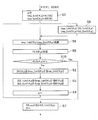
次に図9参照し、反復スペクトル引き算部16における詳細動作を説明する。なお、図9は、あるフレームの処理を示しており、フレームごとに、図9に示す処理が繰り返される。
新たなフレームになり、新たなフレーム(現フレームK)の周波数領域信号X1(f,K)、X2(f,K)がFFT部11から与えられると、反復回数カウンタpが0に、被減算信号tmp_1ch(f,K,p)およびtmp_2ch(f,K,p)がそれぞれ、周波数領域信号X1(f,K)、X2(f,K)に初期化される(ステップS1)。
その後、現反復回数における被減算信号tmp_1ch(f,K,p)およびtmp_2ch(f,K,p)に基づいて、(8)式に従って、雑音信号N(f,K,p)が形成される(ステップS2)。
さらに、現反復回数における被減算信号tmp_1ch(f,K,p)およびtmp_2ch(f,K,p)と、雑音信号N(f,K,p)とに基づいて、(9)式および(10)式に従って、現反復回数におけるスペクトル引き算処理が実行され、スペクトル引き算処理後信号SS_1ch(f,K,p)およびSS_2ch(f,K,p)が形成される(ステップS3)。
次に、反復回数カウンタpが1インクリメントされた後(ステップS4)、更新された反復回数カウンタpが反復回数制御部15から出力された反復回数Θ(K)より小さいか否かが判定される(ステップS5)。
更新された反復回数カウンタpが反復回数制御部15から出力された反復回数Θ(K)より小さい場合には、被減算信号tmp_1ch(f,K,p)およびtmp_2ch(f,K,p)がそれぞれ、前回の反復回数でのスペクトル引き算処理後信号SS_1ch(f,K,p-1)およびSS_2ch(f,K,p-1)に更新された後(ステップS6)、上述したステップS2に移行する。
これに対して、更新された反復回数カウンタpが反復回数制御部15から出力された反復回数Θ(K)に一致した場合には、その時点で得られているスペクトル引き算処理後信号SS_1ch(f,K,p)およびSS_2ch(f,K,p)の一方が、反復スペクトル引き算後信号SS_out(f,K)としてIFFT部17に与えられ、また、フレームを規定するパラメータKが1だけ増加され(ステップS7)、次のフレームの処理に移行する。
第1の実施例によれば、妨害音声の到来方位に応じて、反復スペクトル引き算処理の反復回数を適応的に定めて、その反復回数だけ反復スペクトル引き算処理を実行するので、音質と抑圧性能とをバランス良く実現することができる。
これにより、第1の実施例の信号処理装置を、テレビ会議システムや携帯電話やスマートフォンなどの通信装置に適用することで、通話音質の向上が期待できる。
次に、図面を参照し、本発明の第2の実施例にかかる信号処理装置および方法について詳細に説明する。
第2の実施例の信号処理装置および方法も、スペクトル引き算処理を反復して繰り返す反復回数を適応的に制御することを特徴としており、その制御のために利用するパラメータの挙動が第1の実施例とは異なっている。
従来では、スペクトル引き算処理の反復回数が固定であった。しかし、最適な反復回数は、雑音の特性によって変わる。そのため、反復回数を固定にした場合、雑音の抑圧量が不足する恐れがあり、また、反復を繰り返すたびに音声が歪み自然さが損なわれる場合があり、反復回数を徒に多くしても不都合が生じる。そのため、第2の実施例では、歪みやミュージカルノイズが少ない音質の自然さと、抑圧性能とがバランス良く実現されるような最適な反復回数を設定することを意図している。
第2の実施例では、コヒーレンスCOH(K,p)の挙動を反復の終了判定に利用しており、以下では、利用することとした理由を説明する。
(7)式に示すような平均処理することでコヒーレンスCOH(K,p)を算出させるコヒーレンスフィルタ係数coef(f,K,p)は、(6)式に示すように、左右に死角を有する信号成分の相互相関でもあるので、相関が大きい場合は、到来方位には偏りがない正面から到来する音声成分であり、相関が小さい場合は、到来方位が右か左に偏った成分である、というように入力音声の到来方位とも対応付けられる。
実際に、コヒーレンスフィルタ係数coef(f,K,p)を全ての周枚数成分で平均した値であるコヒーレンスCOH(K,p)を(6)式および(7)式に従って算出して挙動を確認すると、反復回数が増すほど、雑音区間におけるコヒーレンスCOH(K,p)は増大していき、横から到来する成分の寄与が小さくなっていくことが確認できる。
しかし、必要以上に反復した場合には、正面から到来する成分まで抑圧されるようになり、音質が歪む。そして、その際、コヒーレンスCOH(K,p)は正面から到来する成分の影響が小さくなるため減少していく。
以上のような反復回数に応じたコヒーレンスCOH(K,p)の挙動から、コヒーレンスCOH(K,p)が極大値をとる反復回数が、抑圧性能と音質とのバランスがとれる回数であると考えられる。
そこで、第2の実施例では、反復ごとのコヒーレンスCOH(K,p)を観測し、コヒーレンスCOH(K,p)の変化(挙動)が増加から減少に転じた時点で反復処理を終了することとした。これにより、最適な反復回数で反復スペクトル引き算処理を実行させることができる。
第2の実施例に係る信号処理装置の構成を図10に示し、第1の実施例に係る図1との同一部分、または対応部分には同一符号を付して示している。
第2の実施例の信号処理装置1Aは、一対のマイクm1、m2、FFT部11、第1の指向性形成部12、第2の指向性形成部13、コヒーレンス計算部14、反復回数制御部15A、反復スペクトル引き算部16AおよびIFFT部17を有し、反復回数制御部15Aおよび反復スペクトル引き算部16Aを有することが第1の実施例と異なっている。
第2の実施例の反復スペクトル引き算部16Aは、各反復回数での被減算信号tmp_1ch(f,K,p)およびtmp_2ch(f,K,p)がそれぞれ、第1および第2の指向性形成部12および13に出力させ、その出力に応じて、反復回数制御部15Aが出力した反復終了フラグFLG(K,p)を取込み、反復終了フラグFLG(K,p)がオフのときに現反復回数pでのスペクトル引き算処理を実行し、反復終了フラグFLG(K,p)がオンのときに現反復回数pでのスペクトル引き算処理を実行しないで、反復スペクトル引き算処理を終了させる。
なお、上述したように、第2の実施例の場合、第1の指向性形成部12および第2の指向性形成部13にはそれぞれ、被減算信号tmp_1ch(f,K,p)、tmp_2ch(f,K,p)が入力され、この入力信号に対して、第1の実施例と同様な演算を施して、指向性信号B1(f,K,p)、B2(f,K,p)を形成する。
第2の実施例の反復回数制御部15Aは、コヒーレンス計算部14から与えられたコヒーレンスCOH(K,p)の変化が増加から減少に転じたかを判別し、転じていない場合にオフをとり、転じた場合にオンをとる反復終了フラグFLG(K,p)を反復スペクトル引き算部16Aに与える。
第2の実施例に係る反復スペクトル引き算部16Aの詳細構成を図11に示し、第1の実施例に係る図5との同一部分、または対応部分には同一符号を付して示している。
反復スペクトル引き算部16Aは、入力信号受信部21A、反復回数カウンタ・被減算信号初期化部22、被減算信号送信・反復終了フラグ受信部28、反復実施可否制御・反復回数カウンタ更新部25A、第3の指向性形成部23、スペクトル引き算処理部24、被減算信号更新部26およびスペクトル引き算処理後信号送信部27を有する。
入力信号・反復回数受信部21Aは、FFT部11から出力された周波数領域信号X1(f,K)、X2(f,K)を受け取る。
反復回数カウンタ・被減算信号初期化部22は、第1の実施例と同様であるので、その説明は省略する。
被減算信号送信・反復終了フラグ受信部28は、現反復回数における被減算信号tmp_1ch(f,K,p)、tmp_2ch(f,K,p)をそれぞれ第1の指向性形成部12、第2の指向性形成部13に送信すると共に、反復回数制御部15Aが送信した反復終了フラグFLG(K,p)を受け取る。
反復実施可否制御・反復回数カウンタ更新部25Aは、受け取った反復終了フラグFLG(K,p)がオンかオフかを判定し、反復終了フラグFLG(K,p)がオフの場合にはスペクトル引き算処理の反復を継続するように各部を制御し、反復終了フラグFLG(K,p)がオンの場合にはスペクトル引き算処理の反復繰り返しを終了するように各部を制御するものである。また、反復実施可否制御・反復回数カウンタ更新部25Aは、反復終了フラグFLG(K,p)がオフの場合に反復回数カウンタpを1インクリメントする。
第3の指向性形成部23、スペクトル引き算処理部24、被減算信号更新部26およびスペクトル引き算処理後信号送信部27は、第1の実施例と同様であるので、その説明は省略する。
第2の実施例に係る反復回数制御部15Aの詳細構成を図12に示す。ここで、反復回数制御部15Aは、コヒーレンス受信部31、コヒーレンス挙動判定部32A、前コヒーレンス記憶部33Aおよび反復終了フラグ送信部34Aを有する。
コヒーレンス受信部31は、第1の実施例と同様に、コヒーレンス計算部14から出力されたコヒーレンスCOH(K,p)を取込む。
コヒーレンス挙動判定部32Aは、受信した現反復回のコヒーレンスCOH(K,p)と、前コヒーレンス記憶部33Aに記憶されている前回の反復回のコヒーレンスCOH(K,p-1)とから、コヒーレンスの挙動を捉えて、反復終了フラグFLG(K,p)を形成し、その後、現反復回のコヒーレンスCOH(K,p)を前コヒーレンス記憶部33Aに記憶させる。
コヒーレンス挙動判定部32Aは、たとえば、現反復回のコヒーレンスCOH(K,p)が前回の反復回のコヒーレンスCOH(K,p-1)より大きい場合に反復終了フラグFLG(K,p)をオフとし、現反復回のコヒーレンスCOH(K,p)が前回の反復回のコヒーレンスCOH(K,p-1)以下の場合に反復終了フラグFLG(K,p)をオンとする。
前コヒーレンス記憶部33Aは、前回の反復回におけるコヒーレンスCOH(K,p-1)を記憶している。
反復終了フラグ送信部34Aは、コヒーレンス挙動判定部32Aが形成した現反復回の反復終了フラグFLG(K,p)を反復スペクトル引き算部16Aに与える。
次に、図面を参照し、第2の実施例の信号処理装置1Aの全体動作および反復スペクトル引き算部16Aにおける詳細動作を説明する。
一対のマイクm1およびm2から入力された信号s1(n)、s2(n)はそれぞれ、FFT部11によって時間領域から周波数領域の信号X1(f,K)、X2(f,K)に変換されて反復スペクトル引き算部16Aに与えられる。
反復スペクトル引き算部16Aにおいては、反復回数ごとに、その反復回数での被減算信号tmp_1ch(f,K,p)、tmp_2ch(f,K,p)が形成され、これら被減算信号tmp_1ch(f,K,p)、tmp_2ch(f,K,p)が対応する第1または第2の指向性形成部12または13に与えられる。
これら被減算信号tmp_1ch(f,K,p)、tmp_2ch(f,K,p)に基づき、第1および第2の指向性形成部12および13のそれぞれによって、所定の方位に死角を有する第1および第2の指向性信号B1(f,K,p)およびB2(f,K,p)が生成される。次に、コヒーレンス計算部14において、第1および第2の指向性信号B1(f,K,p)およびB2(f,K,p)を適用して、(6)式および(7)式の演算が実行され、コヒーレンスCOH(K,p)が算出され、反復回数制御部15Aにおいて、算出された現反復回数のコヒーレンスCOH(K,p)と、内蔵する前回の反復回数におけるコヒーレンスCOH(K,p-1)とに基づいて、反復終了フラグFLG(K,p)が形成されて反復スペクトル引き算部16Aに与えられる。
反復スペクトル引き算部16Aにおいては、周波数領域信号X1(f,K)およびX2(f,K)を当初の被減算信号とした、スペクトル引き算処理が、反復終了フラグFLG(K,p)がオンとなる反復回数まで繰り返し実行され、得られた反復スペクトル引き算後信号SS_out(f,K)がIFFT部17に与えられる。
IFFT部17においては、周波数領域信号である反復スペクトル引き算後信号SS_out(f,K)が、逆高速フーリエ変換によって、時間領域信号y(n)に変換され、この時間領域信号y(n)が出力される。
次に図13を参照し、反復スペクトル引き算部16Aにおける詳細動作を説明する。なお、図13は、あるフレームの処理を示しており、フレームごとに、図13に示す処理が繰り返される。また、図13において、第1の実施例に係る図9との同一ステップには同一符号を付して示している。
新たなフレームになり、新たなフレーム(現フレームK)の周波数領域信号X1(f,K)、X2(f,K)がFFT部11から与えられると、反復スペクトル引き算部16Aは、反復回数カウンタpを0に、被減算信号tmp_1ch(f,K,p)およびtmp_2ch(f,K,p)をそれぞれ、周波数領域信号X1(f,K)、X2(f,K)に初期化する(ステップS1)。
その後、反復スペクトル引き算部16Aは、現反復回数の被減算信号tmp_1ch(f,K,p)およびtmp_2ch(f,K,p)をそれぞれ、第1の指向性形成部12、第2の指向性形成部13に送信し(ステップS8)、それに応じて形成されて送信されてきた反復終了フラグFLG(K,p)を受信する(ステップS9)。
反復スペクトル引き算部16Aは、受信した反復終了フラグFLG(K,p)がオンか否かを判定する(ステップS10)。
受信した反復終了フラグFlg(K,p)がオフの場合には、反復スペクトル引き算部16Aは、現反復回における被減算信号tmp_1ch(f,K,p)およびtmp_2ch(f,K,p)に基づいて、(8)式に従って、雑音信号N(f,K,p)を形成し(ステップS2)、さらに、現反復回における被減算信号tmp_1ch(f,K,p)およびtmp_2ch(f,K,p)と、雑音信号N(f,K,p)とに基づいて、(9)式および(10)式に従って、現反復回におけるスペクトル引き算処理を実行し、スペクトル引き算処理後信号SS_1ch(f,K,p)およびSS_2ch(f,K,p)を形成する(ステップS3)。次に、反復スペクトル引き算部16Aは、反復回数カウンタpを1インクリメントした後(ステップS4)、被減算信号tmp_1ch (f,K,p)およびtmp_2ch(f,K,p)をそれぞれ、前回の反復回数でのスペクトル引き算処理後信号SS_1ch(f,K,p-1)およびSS_2ch(f,K,p-1)に更新した後(ステップS6)、上述したステップS8に移行する。
これに対して、受信した反復終了フラグFlg(K,p)がオンの場合には、反復スペクトル引き算部16Aは、前回の反復回で得られているスペクトル引き算処理後信号SS_1ch(f,K,p-1)およびSS_2ch(f,K,p-1)の一方を、反復スペクトル引き算後信号SS_out(f,K)としてIFFT部17に与え、また、フレームを規定するパラメータKを1だけ増加し(ステップS7)、今回のフレームの処理を終了し、次のフレームの処理に移行する。
第2の実施例によれば、目的音声の到来方位に応じて、反復スペクトル引き算処理の反復繰り返しの終了タイミングを捉え、その終了タイミングになるまで反復スペクトル引き算処理を実行するようにしたので、音質と抑圧性能とをバランス良く実現することができる。
これにより、第2の実施例の信号処理装置を、テレビ会議システムや携帯電話やスマートフォンなどの通信装置に適用することで、通話音質の向上が期待できる。
上述したように、スペクトル引き算処理は、上記実施例で説明されたものに限定されるものではない。上記実施例以外でも、スペクトル引き算処理として公知になっているものは多い。たとえば、雑音信号N(f,K,p)に減算係数を乗算した後に、減算処理を行うようにしてもよい。またたとえば、反復スペクトル引き算後信号SS_out(f,K)にフロアリング処理を施してからIFFT部17に与えるようにしてもよい。
上記第1の実施例では、コヒーレンスCOH(K)を用いて全ての周波数成分で同一の反復回を設定するものを示したが、周波数ごとに異なる反復回を設定するようにしてもよい。この場合は、たとえば、コヒーレンスCOH(K)に代えて、(6)式で得られる周波数成分ごとの相関値coef(f)を用いて反復回を決定するようにすればよい。
第1の実施例では、コヒーレンスCOH(K)が大きいほど反復回数を少なくするようにしたものを示したが、スペクトル引き算における雑音成分の推定方法によっては、逆に、コヒーレンスCOH(K)が大きいほど反復回数を多くするような構成とするようにしてもよい。
また第1の実施例では、コヒーレンスの範囲と反復回数とを予め対応付けておき、今回のコヒーレンスが属する範囲に対応付けられている反復回を反復スペクトル引き算処理での反復回とするものを示したが、コヒーレンスと反復回との関係を予め関数化しておき、今回のコヒーレンスを入力とした関数演算により、反復スペクトル引き算処理での反復回を定めるようにしてもよい。
上記第2の実施例では、現在の反復回でのコヒーレンスが前回の反復回数でのコヒーレンス以下であることが1回生じたことにより、反復回数ごとのコヒーレンスの挙動が増加から減少に転じたと判定するものを示したが、現在の反復回数でのコヒーレンスが前回の反復回数でのコヒーレンス以下であることが所定回、たとえば2回連続したときに、コヒーレンスの挙動が増加から減少に転じたと判定するようにしてもよい。
第2の実施例では、抑圧性能と音質のバランスがとれることを目標として反復回を制御したが、抑圧性能を重視して音質を低めにしたり、反対に、音質を重視して抑圧性能を控え目に設定したりするようにしてもよい。前者の場合であれば、たとえば、コヒーレンスが減少に転じた以降も、予め定められている回数だけ反復処理を繰り返す。後者の場合であれば、たとえば、コヒーレンスが減少に転じた反復回より、予め定められている回数だけ前の反復回でのスペクトル引き算処理後の信号を、出力信号とするようにすればよい。
なお、第1の実施例においても、変換テーブルに記述するコヒーレンスの範囲と反復回との関係を、抑圧性能を重視して音質を低めにするように定めたり、反対に、音質を重視して抑圧性能を控え目に設定したりするように定めてもよい。
上記第2の実施例では、相前後する反復回数でのコヒーレンスの大小に基づいて、反復処理の終了を判定するものを示したが、相前後する反復回でのコヒーレンスの傾き(微分係数)に基づいて、反復処理の終了を判定するようにしてもよい。傾きが0もしくは0±α(αは極大値を判定できる程度の小さな値)の範囲内の値に変化したときに、反復処理を終了させると判定する。傾きは、相前後する反復回数でのコヒーレンスの算出時刻の時間差が一定の場合であれば、相前後する反復回数でのコヒーレンスの差として算出することができ、相前後する反復回数でのコヒーレンスの算出時刻の時間差が一定でない場合であれば、コヒーレンスの算出ごとにその時刻を記録しておき、相前後する反復回でのコヒーレンスの差を、時刻の差で割ることによって算出することができる。
第2の実施例では、コヒーレンスフィルタ係数(周波数成分ごとの相関値であるcoef(f))の平均であるコヒーレンスを反復処理の終了判定に利用するものを示したが、周波数成分ごとのコヒーレンスフィルタ係数coef(0,K,p)~coef(M-1,K,p)の分布の代表値を表す統計量であれば、コヒーレンスに代えて他の統計量、たとえば、メディアンを適用するようにしてもよい。
上記各実施例では、反復処理の継続か終了かの判定に、コヒーレンスCOH(K)を用いたものを示したが、コヒーレンスCOH(K)に代えて、「入力音声信号における目的音声の含有量」という概念を持つ他の特徴量を用いて、反復処理の継続か終了かの判定を行うようにしてもよい。
上記各実施例において、周波数領域の信号で処理していた処理を、可能ならば時間領域の信号で処理するようにしてもよい。
上記各実施例では、一対のマイクが捕捉した信号を直ちに処理する場合を示したが、本発明の処理対象の音声信号はこれに限定されるものではない。たとえば、記録媒体から読み出した一対の音声信号を処理する場合にも、本発明を適用することができ、また、対向装置から送信されてきた一対の音声信号を処理する場合にも、本発明を適用することができる。このような変形実施例の場合であれば、信号処理装置に入力される段階で、既に周波数領域の信号になっていてもよい。
西暦2013年2月26日に出願された日本国特許出願、特願2013-036360号の明細書、特許請求の範囲、添付図面および要約書を含むすべての開示内容は、この明細書にそのすべてが含まれ、参照される。
本発明を特定の実施例を参照して説明したが、本発明はこれらの実施例に限定されるものではない。いわゆる当業者は、本発明の範囲および概念から逸脱しない範囲で、これらの実施例を変更または修正することができることは、認識されるべきである。
Claims (6)
- 雑音成分を含む入力信号を繰り返してスペクトル引き算処理する反復スペクトル引き算部を含み、該スペクトル引き算処理の繰返しによって前記雑音成分を抑制する信号処理装置において、該装置はさらに、
前記入力信号から目的信号の含有量を特徴量として算出する特徴量算出部と、
該特徴量に基づき前記スペクトル引き算処理の反復回数を制御する反復回数制御部とを含むことを特徴とする信号処理装置。 - 請求項1に記載の装置において、前記入力信号は一対の入力信号を含み、該装置はさらに、
該一対の信号に基づき、所定方位に死角を有する指向性特性を有する第1の指向性信号を形成する第1の指向性形成部と、
前記一対の信号に基づき、他の所定方位に死角を有する指向性特性を有する第2の指向性信号を形成する第2の指向性形成部と、
該第1の指向性信号と該第2の指向性信号とから前記特徴量としてコヒーレンスを計算するコヒーレンス計算部とを含むことを特徴とする信号処理装置。 - 請求項2に記載の装置において、前記一対の入力信号は、一対の音声信号であり、
前記反復回数制御部は、前記コヒーレンス計算部が計算した前記コヒーレンスに応じた反復回を定め、前記反復スペクトル引き算部に通知することを特徴とする信号処理装置。 - 請求項2に記載の装置において、前記一対の入力信号は、他の反復回でのスペクトル引き算処理を行う信号であり、
前記反復回数制御部は、前記コヒーレンス計算部が計算した前記コヒーレンスが増大から減少に転じたときに、前記反復スペクトル引き算部へ反復処理の終了を通知することを特徴とする信号処理装置。 - 雑音成分を含む入力信号を繰り返してスペクトル引き算処理する反復スペクトル引き算工程を含み、該スペクトル引き算処理の繰り返しによって前記雑音成分を抑制する信号処理方法において、該方法はさらに、
前記入力信号から目的信号の含有量を特徴量として算出する特徴量算出工程と、
該特徴量に基づき前記スペクトル引き算処理の反復回数を制御する反復回数制御工程とを含むことを特徴とする信号処理方法。 - 雑音成分を含む入力信号を繰り返してスペクトル引き算処理する反復スペクトル引き算処理を行い、該スペクトル引き算処理の繰り返しによって前記雑音成分を抑制する信号処理装置としてコンピュータを機能させる信号処理プログラムが蓄積された非一時的なコンピュータ可読媒体において、前記プログラムはさらに、
前記入力信号から目的信号の含有量を特徴量として算出する特徴量算出処理を行い、
該特徴量に基づき前記スペクトル引き算処理の反復回数を制御する反復回数制御処理を行なうことを特徴とする非一時的なコンピュータ可読媒体。
Priority Applications (1)
| Application Number | Priority Date | Filing Date | Title |
|---|---|---|---|
| US14/770,784 US9659575B2 (en) | 2013-02-26 | 2013-11-20 | Signal processor and method therefor |
Applications Claiming Priority (2)
| Application Number | Priority Date | Filing Date | Title |
|---|---|---|---|
| JP2013036360A JP6221258B2 (ja) | 2013-02-26 | 2013-02-26 | 信号処理装置、方法及びプログラム |
| JP2013-036360 | 2013-02-26 |
Publications (1)
| Publication Number | Publication Date |
|---|---|
| WO2014132500A1 true WO2014132500A1 (ja) | 2014-09-04 |
Family
ID=51427790
Family Applications (1)
| Application Number | Title | Priority Date | Filing Date |
|---|---|---|---|
| PCT/JP2013/081244 Ceased WO2014132500A1 (ja) | 2013-02-26 | 2013-11-20 | 信号処理装置および方法 |
Country Status (3)
| Country | Link |
|---|---|
| US (1) | US9659575B2 (ja) |
| JP (1) | JP6221258B2 (ja) |
| WO (1) | WO2014132500A1 (ja) |
Families Citing this family (3)
| Publication number | Priority date | Publication date | Assignee | Title |
|---|---|---|---|---|
| JP6966039B2 (ja) * | 2017-10-25 | 2021-11-10 | 住友電工デバイス・イノベーション株式会社 | 試験装置 |
| CN108257617B (zh) * | 2018-01-11 | 2021-01-19 | 会听声学科技(北京)有限公司 | 一种噪声场景识别系统及方法 |
| CN120523107B (zh) * | 2025-07-24 | 2025-11-21 | 中国铁塔股份有限公司四川省分公司 | 低空作业无人机协同控制方法、系统、设备及介质 |
Citations (6)
| Publication number | Priority date | Publication date | Assignee | Title |
|---|---|---|---|---|
| JPH06274196A (ja) * | 1993-03-23 | 1994-09-30 | Sony Corp | 雑音除去方法および雑音除去装置 |
| JP2004289762A (ja) * | 2003-01-29 | 2004-10-14 | Toshiba Corp | 音声信号処理方法と装置及びプログラム |
| JP2007010897A (ja) * | 2005-06-29 | 2007-01-18 | Toshiba Corp | 音響信号処理方法、装置及びプログラム |
| JP2008070878A (ja) * | 2006-09-15 | 2008-03-27 | Aisin Seiki Co Ltd | 音声信号前処理装置、音声信号処理装置、音声信号前処理方法、及び音声信号前処理用のプログラム |
| JP2010286685A (ja) * | 2009-06-12 | 2010-12-24 | Yamaha Corp | 信号処理装置 |
| JP2011248290A (ja) * | 2010-05-31 | 2011-12-08 | Nara Institute Of Schience And Technology | 雑音抑圧装置 |
Family Cites Families (17)
| Publication number | Priority date | Publication date | Assignee | Title |
|---|---|---|---|---|
| US5299148A (en) * | 1988-10-28 | 1994-03-29 | The Regents Of The University Of California | Self-coherence restoring signal extraction and estimation of signal direction of arrival |
| JP3278486B2 (ja) | 1993-03-22 | 2002-04-30 | セコム株式会社 | 日本語音声合成システム |
| US5848105A (en) * | 1996-10-10 | 1998-12-08 | Gardner; William A. | GMSK signal processors for improved communications capacity and quality |
| US6678211B2 (en) * | 1998-04-03 | 2004-01-13 | The Board Of Trustees Of The Leland Stanford Junior University | Amplified tree structure technology for fiber optic sensor arrays |
| US6885746B2 (en) * | 2001-07-31 | 2005-04-26 | Telecordia Technologies, Inc. | Crosstalk identification for spectrum management in broadband telecommunications systems |
| JP2004021127A (ja) * | 2002-06-19 | 2004-01-22 | Canon Inc | 磁性トナー、該トナーを用いた画像形成方法及びプロセスカートリッジ |
| US7305056B2 (en) * | 2003-11-18 | 2007-12-04 | Ibiquity Digital Corporation | Coherent tracking for FM in-band on-channel receivers |
| US7453961B1 (en) * | 2005-01-11 | 2008-11-18 | Itt Manufacturing Enterprises, Inc. | Methods and apparatus for detection of signal timing |
| JP5257366B2 (ja) * | 2007-12-19 | 2013-08-07 | 富士通株式会社 | 雑音抑圧装置、雑音抑圧制御装置、雑音抑圧方法及び雑音抑圧プログラム |
| EP2196988B1 (en) * | 2008-12-12 | 2012-09-05 | Nuance Communications, Inc. | Determination of the coherence of audio signals |
| US8340234B1 (en) * | 2009-07-01 | 2012-12-25 | Qualcomm Incorporated | System and method for ISI based adaptive window synchronization |
| US8682006B1 (en) * | 2010-10-20 | 2014-03-25 | Audience, Inc. | Noise suppression based on null coherence |
| US9185490B2 (en) * | 2010-11-12 | 2015-11-10 | Bradley M. Starobin | Single enclosure surround sound loudspeaker system and method |
| US8525868B2 (en) * | 2011-01-13 | 2013-09-03 | Qualcomm Incorporated | Variable beamforming with a mobile platform |
| WO2012117374A1 (en) * | 2011-03-03 | 2012-09-07 | Technion R&D Foundation | Coherent and self - coherent signal processing techniques |
| JP5817366B2 (ja) * | 2011-09-12 | 2015-11-18 | 沖電気工業株式会社 | 音声信号処理装置、方法及びプログラム |
| GB2495129B (en) * | 2011-09-30 | 2017-07-19 | Skype | Processing signals |
-
2013
- 2013-02-26 JP JP2013036360A patent/JP6221258B2/ja active Active
- 2013-11-20 US US14/770,784 patent/US9659575B2/en active Active
- 2013-11-20 WO PCT/JP2013/081244 patent/WO2014132500A1/ja not_active Ceased
Patent Citations (6)
| Publication number | Priority date | Publication date | Assignee | Title |
|---|---|---|---|---|
| JPH06274196A (ja) * | 1993-03-23 | 1994-09-30 | Sony Corp | 雑音除去方法および雑音除去装置 |
| JP2004289762A (ja) * | 2003-01-29 | 2004-10-14 | Toshiba Corp | 音声信号処理方法と装置及びプログラム |
| JP2007010897A (ja) * | 2005-06-29 | 2007-01-18 | Toshiba Corp | 音響信号処理方法、装置及びプログラム |
| JP2008070878A (ja) * | 2006-09-15 | 2008-03-27 | Aisin Seiki Co Ltd | 音声信号前処理装置、音声信号処理装置、音声信号前処理方法、及び音声信号前処理用のプログラム |
| JP2010286685A (ja) * | 2009-06-12 | 2010-12-24 | Yamaha Corp | 信号処理装置 |
| JP2011248290A (ja) * | 2010-05-31 | 2011-12-08 | Nara Institute Of Schience And Technology | 雑音抑圧装置 |
Non-Patent Citations (2)
| Title |
|---|
| KOTARO NISHIKAWA ET AL.: "Hanpuku Spectral Subtraction ni Okeru Musical Noise Teigenho no Kento", REPORT OF THE 2009 AUTUMN MEETING, THE ACOUSTICAL SOCIETY OF JAPAN, September 2009 (2009-09-01), pages 149 - 150 * |
| SHIN'YA OGATA ET AL.: "Iterative Spectral Subtraction Method for Reduction of Musical Noise", REPORT OF THE 2001 SPRING MEETING, THE ACOUSTICAL SOCIETY OF JAPAN -I, March 2001 (2001-03-01), pages 387 - 388 * |
Also Published As
| Publication number | Publication date |
|---|---|
| JP2014164191A (ja) | 2014-09-08 |
| US20160005418A1 (en) | 2016-01-07 |
| JP6221258B2 (ja) | 2017-11-01 |
| US9659575B2 (en) | 2017-05-23 |
Similar Documents
| Publication | Publication Date | Title |
|---|---|---|
| JP5817366B2 (ja) | 音声信号処理装置、方法及びプログラム | |
| JP6196320B2 (ja) | 複数の瞬間到来方向推定を用いるインフォ−ムド空間フィルタリングのフィルタおよび方法 | |
| JP5805365B2 (ja) | ノイズ推定装置及び方法とそれを利用したノイズ減少装置 | |
| JP5672770B2 (ja) | マイクロホンアレイ装置及び前記マイクロホンアレイ装置が実行するプログラム | |
| CN111128210B (zh) | 具有声学回声消除的音频信号处理的方法和系统 | |
| JP7639070B2 (ja) | ギャップ信頼度を用いた背景雑音推定 | |
| US20090279715A1 (en) | Method, medium, and apparatus for extracting target sound from mixed sound | |
| KR102076760B1 (ko) | 다채널 마이크를 이용한 칼만필터 기반의 다채널 입출력 비선형 음향학적 반향 제거 방법 | |
| JP5838861B2 (ja) | 音声信号処理装置、方法及びプログラム | |
| US20200286501A1 (en) | Apparatus and a method for signal enhancement | |
| CN114724574B (zh) | 一种期望声源方向可调的双麦克风降噪方法 | |
| JP6221257B2 (ja) | 信号処理装置、方法及びプログラム | |
| JP6221258B2 (ja) | 信号処理装置、方法及びプログラム | |
| CN111445916A (zh) | 一种会议系统中音频去混响方法、装置及存储介质 | |
| JP6314475B2 (ja) | 音声信号処理装置及びプログラム | |
| JP6631127B2 (ja) | 音声判定装置、方法及びプログラム、並びに、音声処理装置 | |
| KR20080000478A (ko) | 휴대 단말기에서 복수의 마이크들로 입력된 신호들의잡음을 제거하는 방법 및 장치 | |
| JP6903947B2 (ja) | 非目的音抑圧装置、方法及びプログラム | |
| JP6638248B2 (ja) | 音声判定装置、方法及びプログラム、並びに、音声信号処理装置 | |
| EP3225037A1 (en) | Method and apparatus for generating a directional sound signal from first and second sound signals | |
| JP6295650B2 (ja) | 音声信号処理装置及びプログラム | |
| JP6221463B2 (ja) | 音声信号処理装置及びプログラム | |
| JP6263890B2 (ja) | 音声信号処理装置及びプログラム | |
| JP6102144B2 (ja) | 音響信号処理装置、方法及びプログラム | |
| JP6361360B2 (ja) | 残響判定装置及びプログラム |
Legal Events
| Date | Code | Title | Description |
|---|---|---|---|
| 121 | Ep: the epo has been informed by wipo that ep was designated in this application |
Ref document number: 13876427 Country of ref document: EP Kind code of ref document: A1 |
|
| DPE1 | Request for preliminary examination filed after expiration of 19th month from priority date (pct application filed from 20040101) | ||
| NENP | Non-entry into the national phase |
Ref country code: DE |
|
| WWE | Wipo information: entry into national phase |
Ref document number: 14770784 Country of ref document: US |
|
| 122 | Ep: pct application non-entry in european phase |
Ref document number: 13876427 Country of ref document: EP Kind code of ref document: A1 |