WO2014132498A1 - Sandal - Google Patents
Sandal Download PDFInfo
- Publication number
- WO2014132498A1 WO2014132498A1 PCT/JP2013/081234 JP2013081234W WO2014132498A1 WO 2014132498 A1 WO2014132498 A1 WO 2014132498A1 JP 2013081234 W JP2013081234 W JP 2013081234W WO 2014132498 A1 WO2014132498 A1 WO 2014132498A1
- Authority
- WO
- WIPO (PCT)
- Prior art keywords
- main body
- sandal
- holding
- wearer
- right direction
- Prior art date
Links
Images


Classifications
-
- A—HUMAN NECESSITIES
- A43—FOOTWEAR
- A43B—CHARACTERISTIC FEATURES OF FOOTWEAR; PARTS OF FOOTWEAR
- A43B13/00—Soles; Sole-and-heel integral units
- A43B13/14—Soles; Sole-and-heel integral units characterised by the constructive form
- A43B13/143—Soles; Sole-and-heel integral units characterised by the constructive form provided with wedged, concave or convex end portions, e.g. for improving roll-off of the foot
- A43B13/145—Convex portions, e.g. with a bump or projection, e.g. 'Masai' type shoes
-
- A—HUMAN NECESSITIES
- A43—FOOTWEAR
- A43B—CHARACTERISTIC FEATURES OF FOOTWEAR; PARTS OF FOOTWEAR
- A43B3/00—Footwear characterised by the shape or the use
- A43B3/12—Sandals; Strap guides thereon
- A43B3/126—Sandals; Strap guides thereon characterised by the shape or layout of the straps
-
- A—HUMAN NECESSITIES
- A43—FOOTWEAR
- A43B—CHARACTERISTIC FEATURES OF FOOTWEAR; PARTS OF FOOTWEAR
- A43B3/00—Footwear characterised by the shape or the use
- A43B3/12—Sandals; Strap guides thereon
- A43B3/128—Sandals; Strap guides thereon characterised by the sole
-
- A—HUMAN NECESSITIES
- A43—FOOTWEAR
- A43B—CHARACTERISTIC FEATURES OF FOOTWEAR; PARTS OF FOOTWEAR
- A43B7/00—Footwear with health or hygienic arrangements
Definitions
- the bottom surface of the footwear is curved in an arc shape so that an intermediate portion in the front-rear direction protrudes downward from both ends in the front-rear direction.
- the present invention has been made by paying attention to such problems existing in the conventional technology.
- the object is to provide a sandal that can provide a sufficient exercise effect.
- a sandal including a main body, a heel holding portion is formed at a rear portion of the main body, and an intermediate portion in the front-rear direction of the bottom surface of the main body is It curves so as to protrude downward from both ends in the direction, and the center of gravity of the sandal is set at the front part of the main body.
- the bottom surface of the main body is curved so that an intermediate portion in the left-right direction protrudes downward from both ends in the left-right direction.
- the bottom surface of the main body has a spherical shape that bulges downward.
- a nostril is provided on the upper surface of the front part of the main body, and an upper holding part for holding the instep is provided at the upper end of the nose.
- the upper holding part is spanned between both ends of the main body in the left-right direction.
- the upper holding portion includes a pair of holding pieces that are close to each other while extending upward from both ends in the left-right direction of the main body, and can be expanded between the tips of both holding pieces.
- the width of the connecting portion in the front-rear direction is narrower than the width of the holding piece, and the thickness of the connecting portion is thinner than the holding piece.
- the front bottom surface of the main body is provided with a non-slip portion.
- the rear part of the main body is provided with a loop that can be hung on a bag.
- the center of gravity is set at the front part of the main body, the wearer is likely to be in a state close to toes when wearing the sandals, and a sufficient exercise effect can be obtained.
- the perspective view which shows the sandal of another example of this invention shows the state which looked at the sandal from diagonally upward of the rear part.
- the perspective view which shows the sandal of another example of this invention shows the state which looked at the sandal from diagonally upward of the rear part.
- Sectional drawing of the main body rear part of the sandal of FIG. The perspective view which shows the sandal of another example from which this invention differs further, and shows the state which looked at the sandal from diagonally upward of the rear part.
- Each sandal 10 includes a main body 11, and the main body 11 includes a skeleton 19 made of hard resin.
- the skeleton part 19 is covered with a jacket part 20 made of a soft resin.
- the jacket part 20 makes the touch which the sandal 10 gives to a sole.
- a hard synthetic resin such as polyurethane resin, polyvinyl chloride resin, or polyester resin is used.
- EVA ethylene-vinyl acetate copolymer resin
- thermoplastic elastomers such as polyethylene elastomers and polystyrene elastomers are used as the soft resin.
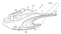
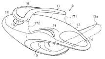
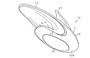
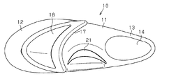
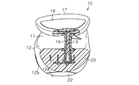
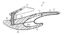
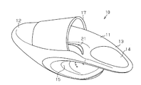
- the main body 11 of the sandal 10 includes a main body front portion 12 on which a front portion including a toe is placed, a main body rear portion 13 on which a rear portion including a heel is placed and acts as a heel holding portion.
- the bottom surface 12 ⁇ / b> A of the main body front portion 12 includes a first curved surface 12 a that is curved so that intermediate portions in the front-rear direction protrude downward from both ends in the front-rear direction, and a left-right direction
- the second curved surface 12b is curved so that the middle portion of the projection protrudes downward from both ends in the left-right direction.
- the curvature of the second curved surface 12b is set larger than the curvature of the first curved surface 12a.
- the radius of curvature of the first curved surface 12a at the contact surface is preferably in the range of 100 to 150 mm
- the radius of curvature of the second curved surface 12b is preferably in the range of 50 to 90 mm. Since the first and second curved surfaces 12a and 12b are thus formed, the bottom surface 12A of the main body 11 has a bulging spherical shape.
- the center of gravity of the sandal 10 is set at the front portion 12 of the main body.
- the weight balance of the sandal 10 and the curvature of the first curved surface 12a are set so that the main body front portion 12 is lower than the main body rear portion 13 when the sandal 10 is not in use.
- the weight of the wearer is supported by the main body front portion 12.
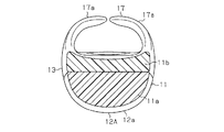
- On the upper surface of the rear portion 13 of the main body a heel mounting portion 14 formed in a gentle concave shape is formed.
- the heel mounting portion 14 is made of a soft material and has a substantially egg shape in plan view.
- a concave portion 15 is formed at the bottom of the main body rear portion 13 so as to open toward the rear and both sides.
- the concave portion 15 is configured to reduce the mass of the main body rear portion 13 and shift the entire center of gravity of the sandal 10 to the main body front portion 12. Thereby, it is comprised so that the weight balance of the whole sandal 10 may become near.
- a nose 16 that protrudes so as to be sandwiched between the toe and forefinger is formed on the upper surface of the main body front portion 12.
- the umbilical cord 16 is disposed slightly deviated on the inner side of the foot toward the sandals for the left foot from the center position in the left-right direction on the upper surface of the main body front portion 12. Further, the umbilical cord 16 is inclined so that the upper part thereof is disposed rearward of the lower part.
- the cross section of the umbilical cord 16 is formed in a substantially elliptical shape that is long in the front-rear direction. For this reason, it is easy to pinch between the thumb and the index finger, and when the wearer wears the sandal 10, the wearer can firmly hold the snare 16 in a stable state with the thumb and the index finger.
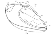
- an upper holding portion 17 is formed at the upper end portion of the umbilical cord 16 so as to extend rearward so as to hit the instep.
- the instep holding portion 17 has a curved shape along the instep surface.
- a metallic luster layer 18 by plating is provided on the upper surface of the upper holding portion 17 to enhance the design.
- a protrusion 21 that presses the arch of the sole of the foot is provided on the upper surface of the main body 11 between the main body front portion 12 and the main body rear portion 13.
- the protrusion 21 is formed in a curved shape so as to hit almost the entire arch when the sandal 10 is worn.
- the wearer puts the snare 16 between the thumb of the toe 25 and the forefinger and puts the sandal 10 on the instep holding portion 17 on the instep.
- a load on the lower part of the front part acts on the wearer. Therefore, the wearer is in a state close to standing on the toes.
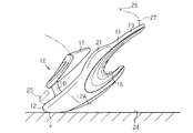
- the lower surface of the main body 11 is formed in a substantially spherical shape as a whole by the first curved surface 12a and the second curved surface 12b, the lower surface of the main body 11 is substantially in point contact with the floor surface.
- the wearer of the sandal 10 needs to balance in the front-back direction, the left-right direction, and the synthetic
- the wearer's foot 26 is arranged such that the toes 25 are lower than the heel 27, so that the wearer increases the weight of the toes 25. It will be supported by nearby parts. Accordingly, a large load acts not only on the calf muscles and thigh muscles, but also on the entire lower limbs, even in a stationary state or not in a stationary state, and these muscles are strongly stimulated and tightened.
- the center of gravity of the sandal 10 of the above-described embodiment is on the front side, in the wearing state, the center of gravity of the wearer moves forward, and the wearer is guided to a forward leaning posture. In order to resist this, in other words, the wearer is in a state of being close to the tiptoe to struggle. Therefore, since a heavy load is applied to the calves and thighs, the wearer of the sandal 10 can obtain an effective exercise effect and realize a healthy beautiful leg. In addition, since the wearer's heel is supported at the rear part of the main body 11, the wearer can stand up and walk in a stable state.
- the sandal 10 of the above embodiment includes the main body 11 having the upper holding part 17.
- the bottom surface of the main body 11 is curved so that an intermediate portion in the front-rear direction protrudes downward from both ends in the front-rear direction.
- the bottom surface of the main body 11 is curved so that an intermediate portion in the left-right direction protrudes downward from both ends in the left-right direction.
- the sandal 10 can be put up in a stable state and can be stood up or walked, and a more effective exercise effect can be obtained for a part such as an ankle. be able to.
- the instep holding portion 17 can be applied to the instep 28 of the foot 26, the sandal 10 is difficult to take off, and operations such as walking can be performed stably.
- the center of gravity of the main body 11 can be set on the front side of the main body 11 without using a weight or the like. Therefore, as described above, the wearer can balance the weight in a forward leaning posture. For this reason, a wearer's weight can be supported by the toe 25 of the whole, and the correct posture which the back muscles extended can be taken. Further, in this state, the wearer is close to a toe-standing posture, so that the calf muscles and thigh muscles are trained. In addition, since the wearer's heel is supported by the heel mounting portion 14, even if the posture is close to toe standing, the wearer's heel can stably stand up or walk.
- the main body 11 has a skeleton 19 made of hard resin, and the skeleton 19 is covered with an outer cover 20 made of soft resin. For this reason, the touch which the sandal 10 gives to a wearer's sole when a wearer wears the sandal 10 can be improved, hold
- a non-slip portion 22 is provided on the bottom surface 12A of the main body front portion 12. Therefore, it is possible to stand and walk in a stable state while wearing the sandal 10 and to prevent the floor surface 24 from being damaged.
- the umbilical cord 16 may be omitted, and the upper holding part 17 may be spanned between both side parts of the main body front part 12 in the left-right direction so as to have a gate shape.
- the chord 16 is omitted, and the upper holding part 17 is configured by a pair of holding pieces 17 a that extend upward from both sides in the left-right direction of the main body front part 12 and approach each other. May be.
- the pair of holding pieces 17a rises toward the upper center of the front portion 12 of the main body, that is, toward the upper surface of the instep, and has elasticity.
- the ends of the holding pieces 17a may be opposed to each other with a space therebetween, or may overlap each other, but the holding pieces 17a are resistant to elasticity according to the height of the upper and the width of the foot in the left-right direction. Since it is expanded, the wearer can appropriately hold the sandal 10 while wearing the sandal 10, and the sandal 10 is easy to wear.
- FIG. 12 and FIG. 13 show an example in which the main body 11 is constituted by core materials 11a and 11b laminated in two stages on the upper and lower sides.
- the core materials 11a and 11b are made of EVA (ethylene vinyl acetate copolymer resin). It is made. These core materials 11a and 11b are integrally connected by, for example, adhesion, thermal welding, ultrasonic welding, and vibration welding. Also.
- the core materials 11a and 11b may be covered with the same or different skin material, and the skin material may be formed by integral molding or ultrasonic bonding. Furthermore, you may comprise the whole core material with a single member.
- the entire upper surface of the main body 11 may be gently dented so that the foot is wrapped from the sole side.
- connecting portions 171 and 172 may be formed between both side portions of the upper holding portion 17 and the main body front portion 12 in the left-right direction.
- the umbilical cord 16 may be omitted.
- connection part 171 corresponding to the inner side of a foot among the connection parts 171 and 172 shown by a dashed-two dotted line in FIG. 1 and the chord 16 may be provided (the connection part 172 corresponding to the outer side of a foot is Not provided).
- the outside of the toe is not covered, and an open appearance can be obtained.
- the nose cord 16 may be omitted, and a pair of holding pieces 17 a extending toward the upper surface of the instep may be provided.
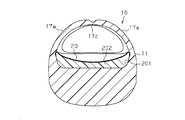
- a connecting portion 17 c having a small width and a small thickness is integrally formed between the holding pieces 17 a.
- the connecting portion 17c may be wound with a cloth ribbon 30 made of black or the like serving as a design accent.
- the ribbon 30 is not always necessary and may be omitted.
- the envelope portion 20 made of EVA constitutes the entire skeleton, and the EVA is softer than the envelope portion 20 in the recess 201 on the upper surface of the envelope portion 20.
- the bottom cover 202 is fitted. Accordingly, the sole cover 202 is in contact with the soles over a wide area and becomes familiar, and exhibits a buffering effect. For this reason, it becomes comfortable.
- a slipping cloth 29 for preventing slipping is attached to the upper surface of the bottom covering 202.
- a loop 13 a that is hung on the wearer's heel may be provided in the main body rear portion 13. If it does in this way, a wearing state will be stabilized and a wearer can walk stably.
- the anti-slip part 22 of the bottom surface 12A of the main body front part 12 is not constituted by a separate member as in the above-described embodiment, but is constituted by uneven portions formed on the bottom surface 12A, or an anti-slip agent is applied. Or may be configured.
- the concave portion 15 at the bottom of the main body rear portion 13 may be omitted.
- the anti-slip portion 22 on the bottom surface 12A of the main body front portion 12 may be omitted.
- a protrusion that stimulates the acupoints on the sole may be provided at an appropriate position on the upper surface of the main body 11.
Abstract
A sandal (10) comprises a main body (11). The main body (11) is configured from a main body forepart (12) which bears a forepart of a foot, including toes, and a main body aft part (13), which bears an aft part of a foot, including the heel. A weight balance of the sandal (10) is set such that the main body forepart (12) is lower than the main body aft part (13). A first curve face (12a), which is curved such that a middle part in the fore-aft direction protrudes further downward in the fore-aft direction than both ends, is formed upon the bottom face of the main body forepart (12), and a second curve face, which is curved such that a middle part in the left-right direction protrudes further downward in the left-right direction than both ends, is formed upon said bottom face. A depression part (15) which opens aft and toward both lateral parts is formed in the bottom part of the main body aft part (13). A thong (16) which is held between the toes is disposed upon the upper face of the main body forepart (12).
Description
本発明は、エクササイズ効果により美脚を実現することが可能なサンダルに関する。
The present invention relates to a sandal capable of realizing a beautiful leg by an exercise effect.
近年、例えば特許文献1及び特許文献2に示されるように、エクササイズ効果を狙ったサンダル等の履物が、提案されている。
In recent years, for example, as shown in Patent Document 1 and Patent Document 2, footwear such as sandals aiming at an exercise effect has been proposed.
特許文献1及び特許文献2に記載された構成において、履物の底面は前後方向における中間部分が前後方向における両端よりも下方に突出するように、円弧状に湾曲している。
In the configurations described in Patent Document 1 and Patent Document 2, the bottom surface of the footwear is curved in an arc shape so that an intermediate portion in the front-rear direction protrudes downward from both ends in the front-rear direction.
特許文献1及び特許文献2に記載されている従来構成のサンダルにおいて、その底面は、上述のように湾曲している。しかし、これらのサンダルの重心は前後方向の中央部に設定されているため、着用者が該サンダルを履いた状態では、その重心は、通常の靴やサンダルと同様であって、充分なエクササイズ効果を得ることが難しかった。
In the sandals having the conventional configuration described in Patent Document 1 and Patent Document 2, the bottom surface is curved as described above. However, since the center of gravity of these sandals is set at the center in the front-rear direction, when the wearer wears the sandals, the center of gravity is the same as that of ordinary shoes and sandals, and a sufficient exercise effect It was difficult to get.
本発明は、このような従来の技術に存在する問題点に着目してなされたものである。その目的は、充分なエクササイズ効果を得ることができるサンダルを提供することにある。
The present invention has been made by paying attention to such problems existing in the conventional technology. The object is to provide a sandal that can provide a sufficient exercise effect.
上記の目的を達成するために、本発明の一態様によると、本体を備えるサンダルが提供され、前記本体の後部に踵保持部が形成され、前記本体の底面は、前後方向における中間部分が前後方向における両端よりも下方に向けて突出するように湾曲しており、前記サンダルの重心が本体の前部に設定されている。
In order to achieve the above object, according to one aspect of the present invention, a sandal including a main body is provided, a heel holding portion is formed at a rear portion of the main body, and an intermediate portion in the front-rear direction of the bottom surface of the main body is It curves so as to protrude downward from both ends in the direction, and the center of gravity of the sandal is set at the front part of the main body.
前記本体の底面は、左右方向における中間部分が左右方向における両端よりも下方に向けて突出するように湾曲していることが望ましい。
It is desirable that the bottom surface of the main body is curved so that an intermediate portion in the left-right direction protrudes downward from both ends in the left-right direction.
前記本体の底面が下方へ向けて膨らんだ球面状であることが望ましい。
It is desirable that the bottom surface of the main body has a spherical shape that bulges downward.
前記本体の前部の上面には鼻緒が設けられ、該鼻緒の上端には、足の甲を保持するための甲保持部が設けられることが望ましい。
It is desirable that a nostril is provided on the upper surface of the front part of the main body, and an upper holding part for holding the instep is provided at the upper end of the nose.
前記本体の前部に、足の甲を保持するための甲保持部が設けられることが望ましい。
It is desirable to provide an instep holding part for holding the instep on the front part of the main body.
前記甲保持部は、前記本体の左右方向における両端の間に掛け渡されていることが望ましい。
It is desirable that the upper holding part is spanned between both ends of the main body in the left-right direction.
前記甲保持部は、前記本体の左右方向における両端から上方へ延びつつ、互いに接近する一対の保持片を備え、両保持片の先端の間は拡開可能であることが望ましい。
It is desirable that the upper holding portion includes a pair of holding pieces that are close to each other while extending upward from both ends in the left-right direction of the main body, and can be expanded between the tips of both holding pieces.
前記保持片の先端の間が連結部により連結されていることが望ましい。
It is desirable that the ends of the holding pieces are connected by a connecting portion.
前記連結部の前後方向の幅は前記保持片の幅より狭く、前記連結部の厚さは前記保持片よりも薄いことが望ましい。
It is desirable that the width of the connecting portion in the front-rear direction is narrower than the width of the holding piece, and the thickness of the connecting portion is thinner than the holding piece.
前記本体の前部の底面は、滑り止め部を備えることが望ましい。
It is desirable that the front bottom surface of the main body is provided with a non-slip portion.
前記本体の後部は、踵に掛けられるループを備えることが望ましい。
It is desirable that the rear part of the main body is provided with a loop that can be hung on a bag.
本発明のサンダルによれば、重心が本体の前部に設定されているため、着用者はサンダルを履いた状態において、つま先立ちに近い状態になりやすく、充分なエクササイズ効果を得ることができる。
According to the sandals of the present invention, since the center of gravity is set at the front part of the main body, the wearer is likely to be in a state close to toes when wearing the sandals, and a sufficient exercise effect can be obtained.
以下、本発明を具体化した実施形態を図1~図10に基づいて詳細に説明する。
Hereinafter, embodiments embodying the present invention will be described in detail with reference to FIGS.
図5及び図6には、左右一対のサンダル10のうちの一方(右足用サンダル)が示されている。各サンダル10は本体11を備え、本体11は、硬質樹脂製の骨格部19を備えている。骨格部19は軟質樹脂製の外被部20によって被覆されている。外被部20は、サンダル10が足裏に与える感触を良好にしている。硬質樹脂としては、ポリウレタン樹脂、ポリ塩化ビニル樹脂、ポリエステル樹脂等の硬質の合成樹脂が用いられる。また、軟質樹脂としては、エチレン-酢酸ビニル共重合樹脂(EVA)のほか、ポリエチレン系エラストマー、ポリスチレン系エラストマー等の熱可塑性エラストマーが用いられる。
5 and 6 show one of the pair of left and right sandals 10 (sandals for the right foot). Each sandal 10 includes a main body 11, and the main body 11 includes a skeleton 19 made of hard resin. The skeleton part 19 is covered with a jacket part 20 made of a soft resin. The jacket part 20 makes the touch which the sandal 10 gives to a sole. As the hard resin, a hard synthetic resin such as polyurethane resin, polyvinyl chloride resin, or polyester resin is used. In addition to ethylene-vinyl acetate copolymer resin (EVA), thermoplastic elastomers such as polyethylene elastomers and polystyrene elastomers are used as the soft resin.
図1及び図2に示すように、サンダル10の本体11は、足指を含む足前部を載せる本体前部12と、踵を含む足後部を載せ、踵保持部として作用する本体後部13とを備える。図5及び図6に示すように、前記本体前部12の底面12Aは、前後方向における中間部分が前後方向における両端よりも下方に向けて突出するように湾曲した第1曲面12aと、左右方向における中間部分が左右方向における両端よりも下方に向けて突出するように湾曲した第2曲面12bとで構成されている。前記第2曲面12bの曲率は、第1曲面12aの曲率より大きく設定されている。例えば、接地面における第1曲面12aの曲率半径は100~150mmの範囲内にあり、第2曲面12bの曲率半径は50~90mmの範囲内にあることが好ましい。そして、このように、第1,第2曲面12a,12bが形成されているため、本体11の底面12Aは膨らんだ球面状をなしている。
As shown in FIGS. 1 and 2, the main body 11 of the sandal 10 includes a main body front portion 12 on which a front portion including a toe is placed, a main body rear portion 13 on which a rear portion including a heel is placed and acts as a heel holding portion. Is provided. As shown in FIGS. 5 and 6, the bottom surface 12 </ b> A of the main body front portion 12 includes a first curved surface 12 a that is curved so that intermediate portions in the front-rear direction protrude downward from both ends in the front-rear direction, and a left-right direction The second curved surface 12b is curved so that the middle portion of the projection protrudes downward from both ends in the left-right direction. The curvature of the second curved surface 12b is set larger than the curvature of the first curved surface 12a. For example, the radius of curvature of the first curved surface 12a at the contact surface is preferably in the range of 100 to 150 mm, and the radius of curvature of the second curved surface 12b is preferably in the range of 50 to 90 mm. Since the first and second curved surfaces 12a and 12b are thus formed, the bottom surface 12A of the main body 11 has a bulging spherical shape.
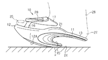
図1及び図2に示すように、サンダル10の重心が本体前部12に設定されている。言い換えれば、サンダル10の不使用状態において、前記本体前部12は、本体後部13よりも低くなるように、サンダル10の重量バランス及び第1曲面12aの曲率が設定されている。これにより、着用者がサンダル10を履いて静止しているときに、着用者の体重を本体前部12で支えるように構成されている。本体後部13の上面には、緩やかな凹状に形成された踵載せ部14が形成されている。踵載せ部14は、軟質材から形成されており、平面視においてほぼ卵形状である。
As shown in FIGS. 1 and 2, the center of gravity of the sandal 10 is set at the front portion 12 of the main body. In other words, the weight balance of the sandal 10 and the curvature of the first curved surface 12a are set so that the main body front portion 12 is lower than the main body rear portion 13 when the sandal 10 is not in use. Thereby, when the wearer wears the sandal 10 and is stationary, the weight of the wearer is supported by the main body front portion 12. On the upper surface of the rear portion 13 of the main body, a heel mounting portion 14 formed in a gentle concave shape is formed. The heel mounting portion 14 is made of a soft material and has a substantially egg shape in plan view.
図1に示すように、前記本体後部13の底部には後方及び両側方に向かって開放するように湾曲した凹部15が形成されている。この凹部15により、本体後部13の質量を減少させ、サンダル10の全体の重心を本体前部12へ移行させるように構成されている。これにより、サンダル10の全体の重量バランスが前寄りになるように構成されている。
As shown in FIG. 1, a concave portion 15 is formed at the bottom of the main body rear portion 13 so as to open toward the rear and both sides. The concave portion 15 is configured to reduce the mass of the main body rear portion 13 and shift the entire center of gravity of the sandal 10 to the main body front portion 12. Thereby, it is comprised so that the weight balance of the whole sandal 10 may become near.
図1及び図5に示すように、前記本体前部12の上面には、足指の親指と人差し指との間に挟まれるように突出した鼻緒16が形成されている。この鼻緒16は、本体前部12の上面において、左右方向における中央位置よりも、左足用のサンダルへ向かって足の内側に若干偏倚して配置されている。また、鼻緒16は、その上部が下部よりも後方へ配置されるように傾斜している。鼻緒16の断面が前後方向に長い略楕円状に形成されている。このため、親指と人差し指とにより挟みやすく、着用者がサンダル10を履いたときに、着用者は親指と人差し指とで鼻緒16を安定した状態でしっかり把持できる。
As shown in FIGS. 1 and 5, a nose 16 that protrudes so as to be sandwiched between the toe and forefinger is formed on the upper surface of the main body front portion 12. The umbilical cord 16 is disposed slightly deviated on the inner side of the foot toward the sandals for the left foot from the center position in the left-right direction on the upper surface of the main body front portion 12. Further, the umbilical cord 16 is inclined so that the upper part thereof is disposed rearward of the lower part. The cross section of the umbilical cord 16 is formed in a substantially elliptical shape that is long in the front-rear direction. For this reason, it is easy to pinch between the thumb and the index finger, and when the wearer wears the sandal 10, the wearer can firmly hold the snare 16 in a stable state with the thumb and the index finger.
図1及び図4に示すように、該鼻緒16の上端部には、足の甲に当たるように後方へ延びる甲保持部17が形成されている。この甲保持部17は、足の甲の面に沿う曲面形状を有している。甲保持部17の上面にはメッキによる金属光沢層18が設けられ、デザイン性が高められている。
As shown in FIGS. 1 and 4, an upper holding portion 17 is formed at the upper end portion of the umbilical cord 16 so as to extend rearward so as to hit the instep. The instep holding portion 17 has a curved shape along the instep surface. A metallic luster layer 18 by plating is provided on the upper surface of the upper holding portion 17 to enhance the design.
図1及び図2に示すように、本体11の上面において、本体前部12と本体後部13との間の部位には、足裏の土踏まずを押圧する突部21が設けられている。この突部21は、サンダル10を履いたとき土踏まずのほぼ全体に当たるように曲面状に形成されている。
As shown in FIGS. 1 and 2, a protrusion 21 that presses the arch of the sole of the foot is provided on the upper surface of the main body 11 between the main body front portion 12 and the main body rear portion 13. The protrusion 21 is formed in a curved shape so as to hit almost the entire arch when the sandal 10 is worn.
図3に示すように、前記本体前部12の底面12Aには、床面との間の滑りを抑制する滑り止め部22が設けられている。滑り止め部22は長円状の底面を有している。この滑り止め部22は、ポリウレタンゴム等の合成ゴム、天然ゴム、および熱可塑性エラストマー等の摩擦係数の高い材料により形成されている。
As shown in FIG. 3, the bottom surface 12A of the main body front portion 12 is provided with a non-slip portion 22 that suppresses slippage between the main body front portion 12 and the floor surface. The anti-slip part 22 has an oval bottom. The anti-slip portion 22 is formed of a material having a high coefficient of friction such as synthetic rubber such as polyurethane rubber, natural rubber, and thermoplastic elastomer.
次に、上記のように構成されたサンダル10について作用を説明する。
Next, the operation of the sandal 10 configured as described above will be described.
図7に示すように、着用者は、足指25の親指と人差し指との間に鼻緒16を挟み込むとともに、甲保持部17に足の甲に配置してサンダル10を履く。サンダル10を着用した状態では、サンダル10の重心が前側にあることから、着用者には前部下方への負荷が作用する。従って、着用者は、つま先立ちに近い状態になる。さらに、本体11の下面が、第1曲面12a及び第2曲面12bによって全体としてほぼ球面状に形成されていることから、本体11の下面は、床面に対してほぼ点接触状態にある。このため、サンダル10の着用者は、前後方向、左右方向、及びその合成方向においてバランスをとる必要がある。しかも、着用者がサンダル10を着用した状態において、着用者の足26は、足指25が、踵27よりも低くなるように配置されることから、着用者は体重の多くを足指25の近傍の部分で支えることになる。従って、静止状態であっても、静止状態でなくてもふくらはぎの筋肉や太ももの筋肉だけでなく、下肢全体に大きな負荷が作用し、それらの筋肉が強く刺激されて、引き締められる。
As shown in FIG. 7, the wearer puts the snare 16 between the thumb of the toe 25 and the forefinger and puts the sandal 10 on the instep holding portion 17 on the instep. In the state where the sandal 10 is worn, since the center of gravity of the sandal 10 is on the front side, a load on the lower part of the front part acts on the wearer. Therefore, the wearer is in a state close to standing on the toes. Furthermore, since the lower surface of the main body 11 is formed in a substantially spherical shape as a whole by the first curved surface 12a and the second curved surface 12b, the lower surface of the main body 11 is substantially in point contact with the floor surface. For this reason, the wearer of the sandal 10 needs to balance in the front-back direction, the left-right direction, and the synthetic | combination direction. In addition, in the state where the wearer wears the sandal 10, the wearer's foot 26 is arranged such that the toes 25 are lower than the heel 27, so that the wearer increases the weight of the toes 25. It will be supported by nearby parts. Accordingly, a large load acts not only on the calf muscles and thigh muscles, but also on the entire lower limbs, even in a stationary state or not in a stationary state, and these muscles are strongly stimulated and tightened.
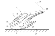
次いで、図8~図10に示すように、着用者がサンダル10を着用した状態で歩行すると、本体11と床面24との接地点pが前後方向に連続移動する。これにより、着用者は、体重移動を滑らかに行うことができる。従って、下肢に大きな負荷が作用するとともに、安定した歩行を行なうことができる。また、本体11と床面24との接地点pが点接触を形成するため、その接地点を中心にサンダル10を回転させることが容易であり、着用者は方向転換を容易に行なうことができる。
Next, as shown in FIGS. 8 to 10, when the wearer walks while wearing the sandal 10, the contact point p between the main body 11 and the floor 24 continuously moves in the front-rear direction. Thereby, the wearer can perform weight shift smoothly. Therefore, a large load acts on the lower limbs and stable walking can be performed. Further, since the grounding point p between the main body 11 and the floor surface 24 forms a point contact, it is easy to rotate the sandal 10 around the grounding point, and the wearer can easily change the direction. .
従って、上記実施形態によれば、以下のような効果を得ることができる。
Therefore, according to the above embodiment, the following effects can be obtained.
(1)上記実施形態のサンダル10は、その重心が前側にあるため、着用状態では、着用者の重心が前方へ向けて移動して、着用者は前傾姿勢に誘導される。着用者はこれに抗するために、言い換えれば踏ん張るためにつま先立ちに近い状態になる。従って、ふくらはぎや太ももに強い負荷がかかるため、サンダル10の着用者は、有効なエクササイズ効果を得て、健康的な美脚を実現できる。加えて、本体11の後部において着用者の踵が支えられるため、着用者は安定した状態で、起立や歩行を行なうことができる。
(1) Since the center of gravity of the sandal 10 of the above-described embodiment is on the front side, in the wearing state, the center of gravity of the wearer moves forward, and the wearer is guided to a forward leaning posture. In order to resist this, in other words, the wearer is in a state of being close to the tiptoe to struggle. Therefore, since a heavy load is applied to the calves and thighs, the wearer of the sandal 10 can obtain an effective exercise effect and realize a healthy beautiful leg. In addition, since the wearer's heel is supported at the rear part of the main body 11, the wearer can stand up and walk in a stable state.
(2)上記実施形態のサンダル10は、甲保持部17を有する本体11を備えている。本体11の底面は、前後方向における中間部分が前後方向における両端よりも下方に向けて突出するように湾曲している。また、本体11の底面は、左右方向における中間部分が左右方向における両端よりも下方に向けて突出するように湾曲している。このため、着用者がサンダル10を履いた状態において、前後方向、左右方向及びその合成方向(斜め方向)にサンダル10が傾動される。従って、着用者は踏ん張ることになり、ふくらはぎ,太股等の下肢に対して有効なエクササイズ効果を得ることができて、上述のように健康的な美脚を実現できる。
(2) The sandal 10 of the above embodiment includes the main body 11 having the upper holding part 17. The bottom surface of the main body 11 is curved so that an intermediate portion in the front-rear direction protrudes downward from both ends in the front-rear direction. Further, the bottom surface of the main body 11 is curved so that an intermediate portion in the left-right direction protrudes downward from both ends in the left-right direction. For this reason, in a state where the wearer wears the sandal 10, the sandal 10 is tilted in the front-rear direction, the left-right direction, and the synthesis direction (oblique direction). Therefore, the wearer will step on and can obtain an effective exercise effect on the lower limbs such as calves and thighs, and a healthy leg can be realized as described above.
(3)また、足の指で鼻緒16を掴むため、サンダル10を安定状態で履いて起立したり、歩行したりすることができるとともに、足首等の部位に対してさらに有効なエクササイズ効果を得ることができる。
(3) In addition, since the snare 16 is grasped by the toes, the sandal 10 can be put up in a stable state and can be stood up or walked, and a more effective exercise effect can be obtained for a part such as an ankle. be able to.
(4)甲保持部17を足26の甲28に当てることができるため、サンダル10が脱げにくく、歩行等の動作を安定に行うことができる。
(4) Since the instep holding portion 17 can be applied to the instep 28 of the foot 26, the sandal 10 is difficult to take off, and operations such as walking can be performed stably.
(5)本体11の後部に凹部15が形成されているため、ウェイト等を用いることなく、本体11の重心を本体11の前側に設定できる。従って、上述のように着用者は前傾姿勢で重量バランスをとることができる。このため、着用者の体重が自身の足指25の全体で支えられて、背筋が伸びた正しい姿勢をとることができる。さらに、この状態では、着用者は、つま先立ちの姿勢に近くなるため、ふくらはぎの筋肉や太ももの筋肉が鍛えられる。加えて、着用者の踵が踵載せ部14によって支持されるため、つま先立ちに近い姿勢であっても、安定して起立したり、歩行したりすることができる。
(5) Since the concave portion 15 is formed in the rear portion of the main body 11, the center of gravity of the main body 11 can be set on the front side of the main body 11 without using a weight or the like. Therefore, as described above, the wearer can balance the weight in a forward leaning posture. For this reason, a wearer's weight can be supported by the toe 25 of the whole, and the correct posture which the back muscles extended can be taken. Further, in this state, the wearer is close to a toe-standing posture, so that the calf muscles and thigh muscles are trained. In addition, since the wearer's heel is supported by the heel mounting portion 14, even if the posture is close to toe standing, the wearer's heel can stably stand up or walk.
(6)本体前部12は接地点pにおいて床面に点接触するため、着用者の体重は接地点pにおいて支えられる。このため、接地点pを中心とした円滑な回転動作を得ることができ、方向転換に好都合である。
(6) Since the main body front portion 12 makes point contact with the floor at the grounding point p, the weight of the wearer is supported at the grounding point p. For this reason, smooth rotation operation | movement centering on the grounding point p can be obtained, and it is convenient for a direction change.
(7)前記本体11は、硬質樹脂製の骨格部19を有し、骨格部19には軟質樹脂製の外被部20が被覆されている。このため、サンダル10の強度や剛性を保持しつつ、着用者がサンダル10を履いたときにサンダル10が着用者の足裏に与える感触を向上させることができる。
(7) The main body 11 has a skeleton 19 made of hard resin, and the skeleton 19 is covered with an outer cover 20 made of soft resin. For this reason, the touch which the sandal 10 gives to a wearer's sole when a wearer wears the sandal 10 can be improved, hold | maintaining the intensity | strength and rigidity of the sandal 10.
(8)前記本体前部12の底面12Aには滑り止め部22が設けられている。従って、サンダル10を履いて安定した状態で起立や歩行をすることができるとともに、床面24を傷付けることを抑えることができる。
(8) A non-slip portion 22 is provided on the bottom surface 12A of the main body front portion 12. Therefore, it is possible to stand and walk in a stable state while wearing the sandal 10 and to prevent the floor surface 24 from being damaged.
(9)前記本体前部12と本体後部13との間には、足裏の土踏まずを押圧する突部21が設けられている。このため、着用者がサンダル10を履いたときに、サンダル10は着用者の足裏を安定した状態で支持することができるとともに、土踏まずを刺激することによって健康を増進することができる。
(9) Between the main body front portion 12 and the main body rear portion 13, a protrusion 21 that presses the arch of the sole is provided. For this reason, when the wearer wears the sandal 10, the sandal 10 can support the sole of the wearer in a stable state and can promote health by stimulating the arch.
上記実施形態を次のように変更して具体化することも可能である。
It is also possible to change the above-described embodiment as follows.
・ 図11に示すように、鼻緒16を省略するとともに、甲保持部17を本体前部12の左右方向における両側部の間に掛け渡して、門形になるように構成してもよい。
As shown in FIG. 11, the umbilical cord 16 may be omitted, and the upper holding part 17 may be spanned between both side parts of the main body front part 12 in the left-right direction so as to have a gate shape.
・ 図12及び図13に示すように、鼻緒16を省略するとともに、甲保持部17を本体前部12の左右方向における両側部から上方へ延びるとともに、互いに接近する一対の保持片17aによって構成してもよい。一対の保持片17aは、本体前部12の中央上部に向けて、つまり足の甲の上面に向けて立ち上がっており、弾性を有する。この場合、両保持片17aの先端は間隔をあけて対向していても、重なっていてもよいが、両保持片17aは甲の高さや左右方向における足の幅に応じて弾性に抗して拡開されるため、着用者がサンダル10を履いた状態で同サンダル10を適切に保持でき、サンダル10は履きやすいものとなる。図12及び図13には、上下に2段積層された芯材11a,11bによって本体11を構成した例が示されており、芯材11a,11bは、EVA(エチレン酢酸ビニル共重合体樹脂)製である。これらの芯材11a,11bは、例えば、接着、熱溶着、超音波溶着、振動溶着によって一体に連結されている。また。芯材11a,11bを同材質あるいは別材質の表皮材で被覆してもよく、表皮材は一体成形や、超音波接着によって施されて良い。さらには、芯材全体を単一の部材で構成してもよい。
As shown in FIGS. 12 and 13, the chord 16 is omitted, and the upper holding part 17 is configured by a pair of holding pieces 17 a that extend upward from both sides in the left-right direction of the main body front part 12 and approach each other. May be. The pair of holding pieces 17a rises toward the upper center of the front portion 12 of the main body, that is, toward the upper surface of the instep, and has elasticity. In this case, the ends of the holding pieces 17a may be opposed to each other with a space therebetween, or may overlap each other, but the holding pieces 17a are resistant to elasticity according to the height of the upper and the width of the foot in the left-right direction. Since it is expanded, the wearer can appropriately hold the sandal 10 while wearing the sandal 10, and the sandal 10 is easy to wear. FIG. 12 and FIG. 13 show an example in which the main body 11 is constituted by core materials 11a and 11b laminated in two stages on the upper and lower sides. The core materials 11a and 11b are made of EVA (ethylene vinyl acetate copolymer resin). It is made. These core materials 11a and 11b are integrally connected by, for example, adhesion, thermal welding, ultrasonic welding, and vibration welding. Also. The core materials 11a and 11b may be covered with the same or different skin material, and the skin material may be formed by integral molding or ultrasonic bonding. Furthermore, you may comprise the whole core material with a single member.
・ 図12に示すように、本体11の上面の全体を緩やかに凹む形状にして、足を足裏側から包み込むようにしてもよい。
As shown in FIG. 12, the entire upper surface of the main body 11 may be gently dented so that the foot is wrapped from the sole side.
・ 図1に2点鎖線で示すように、左右方向における甲保持部17の両側部と本体前部12との間に連結部171,172が形成されてもよい。この場合、鼻緒16は省略されてもよい。
As shown by a two-dot chain line in FIG. 1, connecting portions 171 and 172 may be formed between both side portions of the upper holding portion 17 and the main body front portion 12 in the left-right direction. In this case, the umbilical cord 16 may be omitted.
・ 図1に2点鎖線で示す連結部171,172のうち足の内側に対応する連結部171と、鼻緒16とを備えるように構成してもよい(足の外側に対応する連結部172は設けない)。この構成においては、つま先の外側が覆われず、開放的な外観を得ることができる。
-You may comprise so that the connection part 171 corresponding to the inner side of a foot among the connection parts 171 and 172 shown by a dashed-two dotted line in FIG. 1 and the chord 16 may be provided (the connection part 172 corresponding to the outer side of a foot is Not provided). In this configuration, the outside of the toe is not covered, and an open appearance can be obtained.
・ 図14及び図15に示すように、図12及び図13の構成と同様に、鼻緒16を省略するとともに、足の甲の上面に向けて延びる一対の保持片17aを設けてもよい。ただし、図12及び図13の構成とは異なり、保持片17aの間に幅が狭く厚さが薄い連結部17cが一体に形成されている。このため、連結部17cは甲保持部17の動きをそれほど拘束せず、甲保持部17は足の動きに応じて柔軟に変形する。従って、このサンダル10は、履き心地の良いものとなる。この連結部17cにはデザイン上のアクセントとなる黒色等の布製リボン30が巻き付けられてもよいが、このリボン30は必ずしも必要ではなく、省いてもよい。また、図14及び図15に示される実施形態では、EVAよりなる外被部20が全体の骨格を構成し、その外被部20の上面の凹部201内に外被部20より軟質のEVAよりなる底敷き202が嵌合されている。従って、底敷き202が足裏に広い面積で接触して馴染むとともに、緩衝効果を発揮する。このため、履き心地の良いものとなる。底敷き202の上面には滑り止めのための敷き布29が貼着されている。
As shown in FIGS. 14 and 15, similarly to the configuration of FIGS. 12 and 13, the nose cord 16 may be omitted, and a pair of holding pieces 17 a extending toward the upper surface of the instep may be provided. However, unlike the configuration of FIGS. 12 and 13, a connecting portion 17 c having a small width and a small thickness is integrally formed between the holding pieces 17 a. For this reason, the connection part 17c does not restrain the movement of the instep holding | maintenance part 17 so much, and the instep holding | maintenance part 17 deform | transforms flexibly according to a motion of a leg | foot. Therefore, the sandal 10 is comfortable to wear. The connecting portion 17c may be wound with a cloth ribbon 30 made of black or the like serving as a design accent. However, the ribbon 30 is not always necessary and may be omitted. Further, in the embodiment shown in FIGS. 14 and 15, the envelope portion 20 made of EVA constitutes the entire skeleton, and the EVA is softer than the envelope portion 20 in the recess 201 on the upper surface of the envelope portion 20. The bottom cover 202 is fitted. Accordingly, the sole cover 202 is in contact with the soles over a wide area and becomes familiar, and exhibits a buffering effect. For this reason, it becomes comfortable. A slipping cloth 29 for preventing slipping is attached to the upper surface of the bottom covering 202.
・ 図1及び図2に2点鎖線で示すように、本体後部13に、着用者の踵に掛けられるループ13aを設けてもよい。このようにすれば、着用状態が安定し、着用者は安定して歩行することができる。
As shown by a two-dot chain line in FIG. 1 and FIG. 2, a loop 13 a that is hung on the wearer's heel may be provided in the main body rear portion 13. If it does in this way, a wearing state will be stabilized and a wearer can walk stably.
・ 前記本体前部12の底面12Aの滑り止め部22を、前記実施形態のように別部材で構成することなく、底面12Aに形成された凹凸部で構成したり、滑り止め剤を塗布して構成したりしてもよい。
-The anti-slip part 22 of the bottom surface 12A of the main body front part 12 is not constituted by a separate member as in the above-described embodiment, but is constituted by uneven portions formed on the bottom surface 12A, or an anti-slip agent is applied. Or may be configured.
・ 図1及び図14に2点鎖線で示すように、本体後部13の底部の凹部15を省略してもよい。
As shown by a two-dot chain line in FIGS. 1 and 14, the concave portion 15 at the bottom of the main body rear portion 13 may be omitted.
・ 前記本体前部12の底面12Aの滑り止め部22を省略してもよい。
· The anti-slip portion 22 on the bottom surface 12A of the main body front portion 12 may be omitted.
・ 本体11の上面の適当な位置に、足裏のツボを刺激する突起を設けてもよい。
· A protrusion that stimulates the acupoints on the sole may be provided at an appropriate position on the upper surface of the main body 11.
10…サンダル、11…本体、12…本体前部、12A…底面、12a…第1曲面、12b…第2曲面、13…本体後部、13a…ループ、15…凹部、16…鼻緒、17…甲保持部、17a…保持片、17c…連結部、19…骨格部、20…外被部、21…突部、22…滑り止め部、26…足、27…踵、28…甲。
DESCRIPTION OF SYMBOLS 10 ... Sandal, 11 ... Main body, 12 ... Main body front part, 12A ... Bottom surface, 12a ... First curved surface, 12b ... Second curved surface, 13 ... Main body rear part, 13a ... Loop, 15 ... Recess, 16 ... Throat, 17 ... Upper Holding part, 17a ... Holding piece, 17c ... Connecting part, 19 ... Skeletal part, 20 ... Outer part, 21 ... Protruding part, 22 ... Non-slip part, 26 ... Leg, 27 ... Saddle, 28 ... Instep.
Claims (11)
- 本体を備えるサンダルにおいて、
前記本体の後部に踵保持部が形成され、前記本体の底面は、前後方向における中間部分が前後方向における両端よりも下方に向けて突出するように湾曲しており、前記サンダルの重心が本体の前部に設定されていることを特徴とするサンダル。 In sandals with a body,
A heel holding portion is formed at the rear of the main body, and the bottom surface of the main body is curved such that an intermediate portion in the front-rear direction projects downward from both ends in the front-rear direction, and the center of gravity of the sandal is Sandals characterized by being set at the front. - 前記本体の底面は、左右方向における中間部分が左右方向における両端よりも下方に向けて突出するように湾曲していることを特徴とする請求項1に記載のサンダル。 2. The sandal according to claim 1, wherein the bottom surface of the main body is curved such that an intermediate portion in the left-right direction protrudes downward from both ends in the left-right direction.
- 前記本体の底面が下方へ向けて膨らんだ球面状であることを特徴とする請求項1または2に記載のサンダル。 3. The sandal according to claim 1, wherein the bottom surface of the main body has a spherical shape that bulges downward.
- 前記本体の前部の上面には鼻緒が設けられ、該鼻緒の上端には、足の甲を保持するための甲保持部が設けられていることを特徴とする請求項1または2に記載のサンダル。 The upper surface of the front portion of the main body is provided with a thong, and the upper end of the thong is provided with a back holding portion for holding the back of the foot. Sandals.
- 前記本体の前部に、足の甲を保持するための甲保持部が設けられていることを特徴とする請求項1または2に記載のサンダル。 The sandal according to claim 1 or 2, wherein an instep holding portion for holding an instep is provided at a front portion of the main body.
- 前記甲保持部は、前記本体の左右方向における両端の間に掛け渡されていることを特徴とする請求項5に記載のサンダル。 The sandal according to claim 5, wherein the upper holding part is spanned between both ends of the main body in the left-right direction.
- 前記甲保持部は、前記本体の左右方向における両端から上方へ延びつつ、互いに接近する一対の保持片を備え、両保持片の先端の間は拡開可能であることを特徴とする請求項5に記載のサンダル。 The said upper holding part is provided with a pair of holding piece which mutually approaches while extending upward from the both ends in the left-right direction of the said main body, It can expand between the front-end | tips of both holding pieces. Sandals described in.
- 前記保持片の先端の間は連結部により連結されることを特徴とする請求項7に記載のサンダル。 The sandals according to claim 7, wherein the ends of the holding pieces are connected by a connecting portion.
- 前記連結部の前後方向の幅は前記保持片の幅より狭く、前記連結部の厚さは前記保持片よりも薄いことを特徴とする請求項8に記載のサンダル。 The sandal according to claim 8, wherein the width of the connecting portion in the front-rear direction is narrower than the width of the holding piece, and the thickness of the connecting portion is thinner than the holding piece.
- 前記本体の前部の底面は、滑り止め部を備えることを特徴とする請求項1または2に記載のサンダル。 The sandal according to claim 1 or 2, wherein a bottom surface of a front portion of the main body includes a non-slip portion.
- 前記本体の後部は、踵に掛けられるループを備えることを特徴とする請求項1または2に記載のサンダル。 The sandal according to claim 1, wherein a rear portion of the main body includes a loop that is hung on a heel.
Priority Applications (2)
| Application Number | Priority Date | Filing Date | Title |
|---|---|---|---|
| KR1020157024690A KR20150122168A (en) | 2013-02-27 | 2013-11-20 | Sandal |
| SG11201506117VA SG11201506117VA (en) | 2013-02-27 | 2013-11-20 | Sandal |
Applications Claiming Priority (4)
| Application Number | Priority Date | Filing Date | Title |
|---|---|---|---|
| JP2013-037548 | 2013-02-27 | ||
| JP2013037548 | 2013-02-27 | ||
| JP2013-164188 | 2013-08-07 | ||
| JP2013164188 | 2013-08-07 |
Publications (1)
| Publication Number | Publication Date |
|---|---|
| WO2014132498A1 true WO2014132498A1 (en) | 2014-09-04 |
Family
ID=50958457
Family Applications (1)
| Application Number | Title | Priority Date | Filing Date |
|---|---|---|---|
| PCT/JP2013/081234 WO2014132498A1 (en) | 2013-02-27 | 2013-11-20 | Sandal |
Country Status (7)
| Country | Link |
|---|---|
| JP (2) | JP2015051256A (en) |
| KR (1) | KR20150122168A (en) |
| CN (2) | CN203662098U (en) |
| HK (1) | HK1199800A1 (en) |
| SG (1) | SG11201506117VA (en) |
| TW (1) | TW201433276A (en) |
| WO (1) | WO2014132498A1 (en) |
Cited By (1)
| Publication number | Priority date | Publication date | Assignee | Title |
|---|---|---|---|---|
| WO2017089432A1 (en) * | 2015-11-23 | 2017-06-01 | Werner Staudenmann | Strapless thong sandal |
Families Citing this family (4)
| Publication number | Priority date | Publication date | Assignee | Title |
|---|---|---|---|---|
| EP3753717A4 (en) | 2018-01-31 | 2021-05-05 | ASICS Corporation | Method for producing resin molded body and shoe sole member |
| WO2019150492A1 (en) * | 2018-01-31 | 2019-08-08 | 株式会社アシックス | Shoe sole member and shoes |
| JP7226984B2 (en) * | 2018-12-11 | 2023-02-21 | トップゴルフ キャラウェイ ブランズ コーポレーション | Outsoles, golf training shoes, and balance correction equipment |
| TWI699171B (en) * | 2020-02-21 | 2020-07-21 | 亞東技術學院 | Gait sandals |
Citations (6)
| Publication number | Priority date | Publication date | Assignee | Title |
|---|---|---|---|---|
| JPH07136001A (en) * | 1993-11-11 | 1995-05-30 | Asuteiko:Kk | Running shoes |
| JP3028063U (en) * | 1995-04-10 | 1996-08-30 | 亮 佐藤 | Universal footwear |
| JP3107518U (en) * | 2004-09-01 | 2005-02-03 | 久忠 森川 | Healthy footwear |
| JP3110451U (en) * | 2005-02-15 | 2005-06-23 | 由美子 石川 | slipper |
| JP3142884U (en) * | 2008-03-27 | 2008-07-03 | 良之 楫 | Sandal fitness |
| JP2009254482A (en) * | 2008-04-15 | 2009-11-05 | Seiji Kawabata | Health appliance for footwear |
Family Cites Families (8)
| Publication number | Priority date | Publication date | Assignee | Title |
|---|---|---|---|---|
| JPS4825960U (en) * | 1971-08-05 | 1973-03-28 | ||
| JPH01124102U (en) * | 1988-02-17 | 1989-08-23 | ||
| US20040242382A1 (en) * | 2001-09-14 | 2004-12-02 | Michael Anthony Gibas | Exercise device |
| JP2004121451A (en) * | 2002-10-01 | 2004-04-22 | Masakatsu Shimono | Sandal for stretching |
| JP2004202128A (en) * | 2002-12-26 | 2004-07-22 | Cogit:Kk | Footwear |
| JP2005246024A (en) * | 2004-03-04 | 2005-09-15 | Fumio Kasai | Tiptoe forcing sandal |
| JP2011087717A (en) * | 2009-10-21 | 2011-05-06 | Nosaka:Kk | Shoe soles and shoes |
| US20120073166A1 (en) * | 2010-09-24 | 2012-03-29 | Natalie Bryla | Attachable convex plyometric footwear trainers |
-
2013
- 2013-10-25 JP JP2013222781A patent/JP2015051256A/en active Pending
- 2013-11-20 KR KR1020157024690A patent/KR20150122168A/en not_active Application Discontinuation
- 2013-11-20 WO PCT/JP2013/081234 patent/WO2014132498A1/en active Application Filing
- 2013-11-20 SG SG11201506117VA patent/SG11201506117VA/en unknown
- 2013-11-27 TW TW102143135A patent/TW201433276A/en unknown
- 2013-11-29 JP JP2013248358A patent/JP2015051258A/en active Pending
- 2013-12-23 CN CN201320855488.7U patent/CN203662098U/en not_active Expired - Fee Related
- 2013-12-23 CN CN201310718823.3A patent/CN104000344A/en active Pending
-
2015
- 2015-01-14 HK HK15100378.5A patent/HK1199800A1/en unknown
Patent Citations (6)
| Publication number | Priority date | Publication date | Assignee | Title |
|---|---|---|---|---|
| JPH07136001A (en) * | 1993-11-11 | 1995-05-30 | Asuteiko:Kk | Running shoes |
| JP3028063U (en) * | 1995-04-10 | 1996-08-30 | 亮 佐藤 | Universal footwear |
| JP3107518U (en) * | 2004-09-01 | 2005-02-03 | 久忠 森川 | Healthy footwear |
| JP3110451U (en) * | 2005-02-15 | 2005-06-23 | 由美子 石川 | slipper |
| JP3142884U (en) * | 2008-03-27 | 2008-07-03 | 良之 楫 | Sandal fitness |
| JP2009254482A (en) * | 2008-04-15 | 2009-11-05 | Seiji Kawabata | Health appliance for footwear |
Cited By (1)
| Publication number | Priority date | Publication date | Assignee | Title |
|---|---|---|---|---|
| WO2017089432A1 (en) * | 2015-11-23 | 2017-06-01 | Werner Staudenmann | Strapless thong sandal |
Also Published As
| Publication number | Publication date |
|---|---|
| KR20150122168A (en) | 2015-10-30 |
| SG11201506117VA (en) | 2015-09-29 |
| CN203662098U (en) | 2014-06-25 |
| TW201433276A (en) | 2014-09-01 |
| JP2015051256A (en) | 2015-03-19 |
| JP2015051258A (en) | 2015-03-19 |
| CN104000344A (en) | 2014-08-27 |
| HK1199800A1 (en) | 2015-07-24 |
Similar Documents
| Publication | Publication Date | Title |
|---|---|---|
| US8572868B2 (en) | Footwear having independently articuable toe portions | |
| US20110252665A1 (en) | Soft and elastic shoe pad | |
| WO2014132498A1 (en) | Sandal | |
| JP2013525054A (en) | High mobility shoes | |
| JP3195071U (en) | Shoes with shoehorn function | |
| JP2010264037A (en) | Footwear and footwear insole | |
| JP7166035B1 (en) | Sole plate structure of footwear | |
| JP2009124959A (en) | Footwear for dog | |
| KR100798868B1 (en) | Healthy shoes | |
| US20120079740A1 (en) | Basketball Shoe Sole | |
| KR200341150Y1 (en) | Health shoes | |
| JP3150663U (en) | Footwear indoors to correct stoop | |
| KR20110004571A (en) | The sole of shoe | |
| JP2528487Y2 (en) | Insole structure and insole | |
| KR100575138B1 (en) | A well-being shoes | |
| JP3087900U (en) | footwear | |
| JP3111460U (en) | footwear | |
| JP2008061818A (en) | Footwear for person with invalidity in heel region | |
| TWM393188U (en) | Insole | |
| JP4811811B2 (en) | footwear | |
| TWM504483U (en) | Arch supported shoes | |
| JP3181460U (en) | footwear | |
| TW201632096A (en) | Arch suspension supporting type shoe | |
| KR100963098B1 (en) | Rocker type shoe's sole | |
| JP5451288B2 (en) | Wheelchair shoes and bottom material |
Legal Events
| Date | Code | Title | Description |
|---|---|---|---|
| 121 | Ep: the epo has been informed by wipo that ep was designated in this application |
Ref document number: 13876484 Country of ref document: EP Kind code of ref document: A1 |
|
| NENP | Non-entry into the national phase |
Ref country code: DE |
|
| ENP | Entry into the national phase |
Ref document number: 20157024690 Country of ref document: KR Kind code of ref document: A |
|
| 122 | Ep: pct application non-entry in european phase |
Ref document number: 13876484 Country of ref document: EP Kind code of ref document: A1 |