JP2004202128A - footwear - Google Patents
footwear Download PDFInfo
- Publication number
- JP2004202128A JP2004202128A JP2002377896A JP2002377896A JP2004202128A JP 2004202128 A JP2004202128 A JP 2004202128A JP 2002377896 A JP2002377896 A JP 2002377896A JP 2002377896 A JP2002377896 A JP 2002377896A JP 2004202128 A JP2004202128 A JP 2004202128A
- Authority
- JP
- Japan
- Prior art keywords
- footwear
- stand
- posture
- side edge
- cover
- Prior art date
- Legal status (The legal status is an assumption and is not a legal conclusion. Google has not performed a legal analysis and makes no representation as to the accuracy of the status listed.)
- Pending
Links
Images
Landscapes
- Footwear And Its Accessory, Manufacturing Method And Apparatuses (AREA)
Abstract
【課題】爪先立ちした姿勢への移行、あるいは踵立ちした姿勢への移行を容易にかつ安定に行うことができ、ダイエット効果、シェイプアップ効果を効果的に得ることができ、バランス感覚を効果的に養うことができ、さらにはO脚の矯正、外反母趾を防止することができる履物を提供する。
【解決手段】前記小指装着部側から親指装着部側に向けて先搾まりのテーパ状断面に形成されるとともに、足裏形状に合わせて形成される履物台2の上面に鼻緒5を取り付け、この鼻緒5の前部上面を覆うように帯状のカバー部6を取り付ける。そして前記履物台2の下面に、下に凸の半円柱状の突起部3aを、その履物台2の一側縁から他側縁に渡るように設ける。
【選択図】 図2An object of the present invention is to easily and stably shift to a toe standing position or a heel standing position, to obtain a diet effect and a shape-up effect effectively, and to effectively improve a sense of balance. The present invention provides a footwear that can nourish, correct O-legs, and prevent hallux valgus.
A thong 5 is attached to an upper surface of a footwear stand 2 which is formed in a tapered cross section of a first squeeze from the little finger mounting portion side to the thumb mounting portion side and is formed in accordance with a sole shape. A band-like cover 6 is attached so as to cover the upper surface of the front part of the thong 5. A semi-cylindrical projection 3a that is convex downward is provided on the lower surface of the footwear stand 2 so as to extend from one side edge of the footwear stand 2 to the other side edge.
[Selection] Fig. 2
Description
【0001】
【発明の属する技術分野】
本発明は、主に室内で使用される履物に関するものである。
【0002】
【従来の技術】
従来、バランス感覚を養うため、あるいはダイエット効果を得るために、足底部の下面側に半球状の突起部を設けた履物型のトレーニング器具が提案されている(例えば、特許文献1)。
【0003】
【特許文献1】
特開平9−308706号公報
【0004】
前記特許文献1に記載されたトレーニング器具によれば、半球状の突起部の先端部のみが接地するように歩行もしくは走行を行う場合、使用者は立った姿勢を維持するには全方向への微妙な体重移動を繰返して重心を上手く調整する必要があることから、この器具を履き続けることによって、自然にバランス感覚を養うことができるという効果がある。また、この器具を履き、体の重心を前に傾けて爪先立ちした姿勢をとることにより、ふくらはぎ、大腿部、臀部の筋肉を強化することができ、それによってシェイプアップ効果を得ることができる。さらに、重心を後ろに傾けて踵立ちした姿勢をとることにより、アキレス腱やふくらはぎの筋肉を伸ばすことができ、それによるストレッチ効果を得ることができる。
【0005】
【発明が解決しようとする課題】
しかしながら、前記従来のトレーニング器具においては、半球状の突起部の先端部のみが床面あるいは地面と接地するように構成されているために、あまりにも不安定であり、爪先立ちした姿勢から踵立ちした姿勢に移行したり、歩行したりあるいは、バランス立ちした姿勢を保つことが極めて困難であるという問題点がある。このため、場合によっては、なにかの弾みで左右に重心が偏った際に、転倒したり、足首を負傷したりする恐れがある。また、前述のように余りにも不安定であるために、特定の姿勢をとり続けることが極めて困難であることから、バランス感覚を養う効果や、シェイプアップ効果、ストレッチ効果といった所望の効果を効果的に得ることができないという問題点がある。
【0006】
本発明は、このような問題点を解決するためになされたものであり、爪先立ちした状態、あるいは踵立ちした状態への移行を容易にかつ安定して行うことができ、それぞれの姿勢を長時間維持することができ、この結果ストレッチ効果、シェイプアップ効果等を効果的に得ることのできる履物を提供することを目的とするものである。
【0007】
【課題を解決するための手段および作用・効果】
前記目的を達成するために、本発明による履物は、
足裏型に形成される履物台と、この履物台の親指装着部から小指装着部までを覆うように取り付けられるカバー部を備える履物において、
前記履物台の下面には、下に凸の半円柱状の突起部が、その履物台の一側縁から他側縁に渡って設けられることを特徴とするものである。
【0008】
本発明によれば、履物台の下面に、下に凸の半円柱状の突起部がその履物台の一側縁から他側部に渡る範囲に設けられていることから、履物の回動方向が長手方向(爪先の装着部−踵の装着部方向)にのみ限定されることになる。このため、例えば、何かの弾みで横方向へ体重移動してしまった場合であっても、姿勢が崩れ難いと言う効果を奏する。したがって、前記突起部と底部の後端部とを接地させた踵立ちした姿勢への移行、あるいは、突起部と底部の前端部とを接地させた爪先立ちした姿勢への移行を、前後方向への体重移動を行うことによって容易にかつスムーズに行うことができる。
【0009】
また、踵立ちした姿勢をとった場合であっても、爪先立ちした姿勢をとった場合であっても、前記突起部の一側縁から他側縁に渡る比較的広い範囲が接地した状態となるので、それぞれの姿勢を安定かつ良好に長時間維持することができる。こうして、長時間安定して踵立ちした姿勢を維持することにより、アキレス腱およびふくらはぎに対するストレッチ効果を良好かつ効果的に得ることができる。また、長時間安定して爪先立ちした姿勢を維持することにより、ふくらはぎ、大腿部、臀部の筋肉を強化することによるシェイプアップ効果を良好かつ効果的に得ることができる。また、前述のように突起部の比較的広い範囲と履物台の下部前端部または下部後端部が接地することになるので、爪先立ち歩き、あるいは踵立ち歩きを行うことも可能である。
【0010】
また、前記突起部の比較的広い範囲が接地することになるので、その突起部のみを接地させた状態を比較的長時間維持することができ、それによって、バランス感覚を自然に養うことができる。また、突起部のみを接地させた状態で歩行することもできる。
【0011】
前記突起部は、前記履物台の中央部のやや前方位置に設けられるのが好ましい。このようにすることによって、踵立ちした姿勢をとった際におけるアキレス腱やふくらはぎの伸び具合を適切なものにすることができ、爪先立ちした姿勢をとった際における足首の角度も適度なものとすることができる。
【0012】
また、前記履物台は、前記小指装着部側から親指装着部側に向けて先搾まりのテーパ状断面に形成されるのが良い。このようにすれば、足裏が常に外側を向く状態となり、両膝が自然に身体の中心線側(内側)に移動するため、O脚の矯正を行うことができる。さらに履物台の上面には鼻緒が取り付けられるのが好ましい。こうすることによって、指の間を鼻緒によってしっかりと支えることができるので外反母趾を防止することができる。また、接地面の摩擦抵抗を大にして各姿勢への移行をより安定なものとするために、前記履物台の下面には凹凸部が設けられるのが好ましい。
【0013】
【発明の実施の形態】
次に、本発明による履物の具体的な実施の形態について、図面を参照しつつ説明する。
【0014】
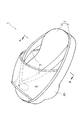
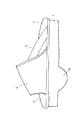
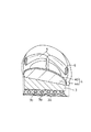
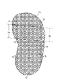
図1には、本発明の一実施形態に係る履物の斜視図が、図2には、同履物の側面図が、図3には同履物の要部断面図(図1のA−A視における要部断面図)が、図4には、同履物の底面図がそれぞれ示されている。なお、図示の履物は左足用のもののみが示されており、右足用のものについては左右対称であるため図示省略されている。
【0015】
本実施形態による履物1は、図1に示されるように、足裏形状に合わせて形成された履物台2と、この履物台2の上面に取り付けられる鼻緒5と、前記履物台2および鼻緒5の前部上面を覆うように取り付けられる帯状のカバー部6とにより構成されている。前記履物台2はEVA樹脂から形成される底部3と、この底部3の上面に接合される足にかかる負担を吸収するためのクッション部4から構成されている。このクッション部4はクッション性を有するとともに、前記履物台2の上面に貼着される低発泡(低反発)ポリウレタン製のスポンジ部4a(図3参照)と、このスポンジ部4aを覆うようにそのスポンジ部4a上に配される布製のカバー4bとから構成されている。なお、本実施形態においては、前記履物台2の長さは、使用者が履物1を履いたときに踵の後端部が履物台2の後端縁から若干はみ出す程度の長さに設定されている。
【0016】
前記鼻緒5は、クッション部4の上面であって、その前部と左右後端部の所要位置に止着されている。また、前記カバー部6は、その両端部がクッション部4の両側縁で、そのクッション部4の前端縁寄りの位置から前後方向の略中央部に至る範囲に縫着されている。こうして、使用時に爪先を除く指の部分と甲部の一部とが前記カバー部6にて覆われる。
【0017】
図2に示されるように、前記履物台2の底部3の下面(接地面)の中央部のやや前方寄りの位置(土踏まずの装着部付近)には、下に凸の半円柱状の突起部3aが、前記底部3の一側縁から他側縁に渡って形成されている。このような位置に突起部3aを設けることによって、踵立ちした姿勢をとった際におけるアキレス腱およびふくらはぎの伸び具合が適切なものとなり、また、爪先立ちした姿勢をとった際における足首の角度が適度なものとなる。
【0018】
前記突起部3aの裏面を含む底部3の裏面(ソール部)には、図4に示されるように、後述の各姿勢への移行をより安定させるため、滑り止め用の凹部7aおよび凸部7bが所定のパターンで設けられている。さらに、前記底部3は、図3に示されるように、全体として外側(小指の装着部側:図3において左側)から内側(親指の装着部側:図3において右側)に向けて先搾まりのテーパ断面状に形成されている。
【0019】
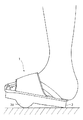
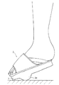
このように構成される履物1によれば、底部3に設けられる突起部3aがその底部3の一側縁から他側縁に渡って設けられていることから、履物1の回動方向が長手方向のみに限定される。このため、何かの弾みで横方向へ体重移動してしまった場合であっても、姿勢が崩れ難いという効果を奏する。したがって、前記突起部3aと底部3の後端部とを接地させた踵立ちした姿勢(図5参照)への移行、あるいは、突起部3aと底部3の前端部とを接地させた爪先立ちした姿勢(図6参照)への移行を、前後方向への体重移動を行うことによって容易にかつスムーズに行うことができる。
【0020】
また、いずれの姿勢をとった場合であっても、前記突起部3aの一側縁から他側縁に渡る比較的広い範囲が接地した状態となるので、それぞれの姿勢を安定かつ良好に長時間維持することができる。こうして、長時間安定して踵立ちした姿勢を維持することによってアキレス腱およびふくらはぎに対するストレッチ効果を良好かつ効果的に得ることができる。また、長時間安定して爪先立ちした姿勢を維持することにより、ふくらはぎ、大腿部、臀部の筋肉を強化することによるシェイプアップ効果を良好かつ効果的に得ることができる。
【0021】
本実施形態の履物1においては、前述のように、回動方向が長手方向に限定され、なおかつ、比較的広い範囲が接地するようにされているため、突起部3aのみを接地させ、前後方向に体重移動を行うことによってバランスをとるという動作を比較的長時間行うことができる。そして、このような動作を長時間行い続けることによってバランス感覚を効果的に養うことができる。
【0022】
また、本実施形態においては、踵立ちした姿勢あるいは爪先立ちした姿勢をとったとしても、前記突起部3aの一側縁から他側縁に渡る比較的広い範囲が接地した状態となるので、踵立ち歩き、爪先立ち歩きを容易に行うことができる。また、突起部3aのみを接地した状態を維持しながらの歩行も容易に行うことができる。
【0023】
また、本実施形態の履物1は、前述のように、底部3が全体として小指の装着側(外側)から親指の装着側(内側)にかけて先搾まりのテーパ断面状に形成されているので、この履物1を履くことで、足の裏面が外側を向くことになり、それによって自然と両膝が身体の中心線に向け移動するので、自然にO脚が矯正されるという作用効果を奏する。
【0024】
さらに、本実施形態の履物1によれば、前記鼻緒5とカバー部6とによって、足の親指が支持されているため、外反母趾を防止できるという効果も有している。
【0025】
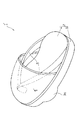
本実施形態においては、爪先を除く指の部分と甲部の一部とを前記カバー部6にて覆うようにした履物1について説明したが、図7に示されるように、指全体と甲部の一部とをカバー部6'にて覆うようにした履物1'であっても、本実施形態と同様の作用効果を得ることができる。
【図面の簡単な説明】
【図1】図1は、本実施形態に係る履物の斜視図である。
【図2】図2は、本実施形態に係る履物の側面図である。
【図3】図3は、図1のA−A視における要部断面図である。
【図4】図4は、本実施形態に係る履物の底面図である。
【図5】図5は、踵先立ちした姿勢をとった際の、足と履物の状態を説明するための図である。
【図6】図6は、爪先立ちした姿勢をとった際の、足と履物の状態を説明するための図である。
【図7】図7は、他の実施形態に係る履物の斜視図である。
【符号の説明】
1、1' 履物
2 履物台
3 底部
3a 突起部
4 クッション部
5 鼻緒
6、6' カバー部
7a 凹部
7b 凸部[0001]
TECHNICAL FIELD OF THE INVENTION
The present invention relates to footwear mainly used indoors.
[0002]
[Prior art]
2. Description of the Related Art Conventionally, in order to develop a sense of balance or to obtain a diet effect, a footwear-type training device provided with a hemispherical protrusion on the lower surface side of a sole has been proposed (for example, Patent Document 1).
[0003]
[Patent Document 1]
JP-A-9-308706
According to the training device described in
[0005]
[Problems to be solved by the invention]
However, in the conventional training device, since only the tip of the hemispherical projection is configured to be in contact with the floor or the ground, it is too unstable, and the heel stands from the tiptoe position. There is a problem that it is extremely difficult to shift to a posture, walk, or maintain a balanced posture. For this reason, in some cases, when the center of gravity is deviated to the left or right due to some momentum, there is a risk of falling or injuring the ankle. In addition, since it is extremely unstable as described above, it is extremely difficult to keep a specific posture, and thus it is possible to effectively provide desired effects such as an effect of cultivating a sense of balance, a shape-up effect, and a stretching effect. There is a problem that cannot be obtained.
[0006]
The present invention has been made in order to solve such a problem, and it is possible to easily and stably shift to a state in which a toe stands or a state in which a heel stands, and hold each posture for a long time. It is an object of the present invention to provide footwear that can be maintained, and as a result, a stretch effect, a shape-up effect, and the like can be effectively obtained.
[0007]
[Means for Solving the Problems and Functions / Effects]
To achieve the above object, the footwear according to the present invention comprises:
In a footwear stand formed into a sole type, and in a footwear including a cover part attached to cover from a thumb mounting part to a little finger mounting part of the footwear base,
A downwardly convex semi-cylindrical projection is provided on the lower surface of the footwear stand from one side edge to the other side edge of the footwear stand.
[0008]
According to the present invention, since a downwardly projecting semi-cylindrical projection is provided on the lower surface of the footwear stand in a range from one side edge to the other side part of the footwear stand, the rotation direction of the footwear stand is provided. Is limited only in the longitudinal direction (the direction in which the toe is attached to the heel). For this reason, for example, even if the weight shifts in the lateral direction due to some momentum, the effect that the posture is hard to collapse is exerted. Therefore, the transition to the heel-standing position in which the protrusion and the rear end of the bottom are grounded, or the transition to the toe-standing position in which the projection and the front end of the bottom are grounded, in the front-rear direction. By shifting the weight, it can be performed easily and smoothly.
[0009]
Also, even when the heel-standing posture is taken or the toe-standing posture is taken, a relatively wide range from one side edge to the other side edge of the protrusion is in a state of being in contact with the ground. Therefore, each posture can be stably and favorably maintained for a long time. In this manner, by maintaining the posture in which the heel stands up stably for a long time, it is possible to obtain a favorable and effective stretching effect on the Achilles tendon and calf. In addition, by maintaining the posture of standing on the toe stably for a long time, it is possible to obtain a good and effective shape-up effect by strengthening the muscles of the calf, the thigh, and the buttocks. Further, as described above, since the relatively wide range of the protrusion and the lower front end or the lower rear end of the footwear stand are in contact with the ground, it is possible to perform a toe stand or a heel stand.
[0010]
In addition, since a relatively wide range of the protrusion is grounded, it is possible to maintain a state in which only the protrusion is grounded for a relatively long time, thereby naturally cultivating a sense of balance. . In addition, it is possible to walk with only the protrusions grounded.
[0011]
Preferably, the protrusion is provided at a slightly forward position in the center of the footwear stand. By doing so, it is possible to make the Achilles tendon and calf stretch properly when taking the heel-standing posture, and to make the ankle angle appropriate when taking the toe-standing posture. Can be.
[0012]
Further, the footwear stand is preferably formed in a tapered cross section of a first compression from the little finger mounting part side to the thumb mounting part side. By doing so, the soles always face outward, and both knees naturally move toward the center line (inside) of the body, so that the O-leg can be corrected. Further, a thong is preferably attached to the upper surface of the footwear stand. By doing so, the space between the fingers can be firmly supported by the thong, so that hallux valgus can be prevented. Further, in order to increase the frictional resistance of the ground contact surface and make the transition to each posture more stable, it is preferable that an uneven portion is provided on the lower surface of the footwear stand.
[0013]
BEST MODE FOR CARRYING OUT THE INVENTION
Next, specific embodiments of footwear according to the present invention will be described with reference to the drawings.
[0014]
FIG. 1 is a perspective view of footwear according to an embodiment of the present invention, FIG. 2 is a side view of the footwear, and FIG. , And FIG. 4 is a bottom view of the footwear. It should be noted that only the footwear for the left foot is shown in the figure, and the footwear for the right foot is not shown because it is bilaterally symmetric.
[0015]
As shown in FIG. 1, the
[0016]
The
[0017]
As shown in FIG. 2, a semi-cylindrical projection projecting downward is provided at a position slightly near the center of the lower surface (ground contact surface) of the
[0018]
As shown in FIG. 4, non-slip
[0019]
According to the
[0020]
Regardless of the posture, the relatively wide range from one side edge to the other side edge of the protrusion 3a is in contact with the ground, so that each posture can be stably and favorably performed for a long time. Can be maintained. In this way, by maintaining the posture of standing on the heel stably for a long period of time, it is possible to obtain a good and effective stretching effect on the Achilles tendon and calf. In addition, by maintaining the posture of standing on the toe stably for a long time, it is possible to obtain a good and effective shape-up effect by strengthening the muscles of the calf, thigh and buttocks.
[0021]
In the
[0022]
Further, in the present embodiment, even if the heel-standing posture or the toe-standing posture is taken, a relatively wide range from one side edge to the other side edge of the projection 3a is in a state of contact with the ground, so Walking and toe standing can be easily performed. Further, it is possible to easily walk while maintaining only the protrusion 3a in the grounded state.
[0023]
Further, as described above, the
[0024]
Furthermore, according to the
[0025]
In the present embodiment, the
[Brief description of the drawings]
FIG. 1 is a perspective view of footwear according to the present embodiment.
FIG. 2 is a side view of the footwear according to the present embodiment.
FIG. 3 is a cross-sectional view of a main part taken along line AA of FIG. 1;
FIG. 4 is a bottom view of the shoe according to the embodiment.
FIG. 5 is a diagram for explaining a state of a foot and footwear when a posture in which a heel stands is taken;
FIG. 6 is a diagram for explaining a state of a foot and footwear when a posture in which a toe stands is taken;
FIG. 7 is a perspective view of footwear according to another embodiment.
[Explanation of symbols]
1, 1 '
Claims (5)
前記履物台の下面には、下に凸の半円柱状の突起部が、その履物台の一側縁から他側縁に渡って設けられることを特徴とする履物。In a footwear stand formed into a sole type, and in a footwear including a cover part attached to cover from a thumb mounting part to a little finger mounting part of the footwear base,
Footwear characterized in that a semi-cylindrical projection projecting downward is provided on a lower surface of the footwear stand from one side edge to the other side edge of the footwear stand.
Priority Applications (1)
| Application Number | Priority Date | Filing Date | Title |
|---|---|---|---|
| JP2002377896A JP2004202128A (en) | 2002-12-26 | 2002-12-26 | footwear |
Applications Claiming Priority (1)
| Application Number | Priority Date | Filing Date | Title |
|---|---|---|---|
| JP2002377896A JP2004202128A (en) | 2002-12-26 | 2002-12-26 | footwear |
Publications (1)
| Publication Number | Publication Date |
|---|---|
| JP2004202128A true JP2004202128A (en) | 2004-07-22 |
Family
ID=32814925
Family Applications (1)
| Application Number | Title | Priority Date | Filing Date |
|---|---|---|---|
| JP2002377896A Pending JP2004202128A (en) | 2002-12-26 | 2002-12-26 | footwear |
Country Status (1)
| Country | Link |
|---|---|
| JP (1) | JP2004202128A (en) |
Cited By (10)
| Publication number | Priority date | Publication date | Assignee | Title |
|---|---|---|---|---|
| JP2008000244A (en) * | 2006-06-21 | 2008-01-10 | Murai:Kk | Shoe sole, footwear, and pad |
| US8277459B2 (en) | 2009-09-25 | 2012-10-02 | Tarsus Medical Inc. | Methods and devices for treating a structural bone and joint deformity |
| KR101209281B1 (en) * | 2011-08-23 | 2012-12-06 | 박균섭 | Functional shoes, and insole for functional shoes |
| JP2013059603A (en) * | 2011-08-22 | 2013-04-04 | Okamoto Kk | Anti-slip sole and anti-slip shoe |
| KR101277084B1 (en) | 2012-11-29 | 2013-06-20 | 오해환 | Health shoe for stretching waist, lower body and calf |
| US8652141B2 (en) | 2010-01-21 | 2014-02-18 | Tarsus Medical Inc. | Methods and devices for treating hallux valgus |
| US8696719B2 (en) | 2010-06-03 | 2014-04-15 | Tarsus Medical Inc. | Methods and devices for treating hallux valgus |
| US20140144046A1 (en) * | 2012-11-10 | 2014-05-29 | Dipka Bhambhani | Footwear |
| US8870876B2 (en) | 2009-02-13 | 2014-10-28 | Tarsus Medical Inc. | Methods and devices for treating hallux valgus |
| JP2015051256A (en) * | 2013-02-27 | 2015-03-19 | 株式会社 Mtg | Sandals |
-
2002
- 2002-12-26 JP JP2002377896A patent/JP2004202128A/en active Pending
Cited By (11)
| Publication number | Priority date | Publication date | Assignee | Title |
|---|---|---|---|---|
| JP2008000244A (en) * | 2006-06-21 | 2008-01-10 | Murai:Kk | Shoe sole, footwear, and pad |
| US8870876B2 (en) | 2009-02-13 | 2014-10-28 | Tarsus Medical Inc. | Methods and devices for treating hallux valgus |
| US8277459B2 (en) | 2009-09-25 | 2012-10-02 | Tarsus Medical Inc. | Methods and devices for treating a structural bone and joint deformity |
| US8795286B2 (en) | 2009-09-25 | 2014-08-05 | Tarsus Medical Inc. | Methods and devices for treating a structural bone and joint deformity |
| US8652141B2 (en) | 2010-01-21 | 2014-02-18 | Tarsus Medical Inc. | Methods and devices for treating hallux valgus |
| US8696719B2 (en) | 2010-06-03 | 2014-04-15 | Tarsus Medical Inc. | Methods and devices for treating hallux valgus |
| JP2013059603A (en) * | 2011-08-22 | 2013-04-04 | Okamoto Kk | Anti-slip sole and anti-slip shoe |
| KR101209281B1 (en) * | 2011-08-23 | 2012-12-06 | 박균섭 | Functional shoes, and insole for functional shoes |
| US20140144046A1 (en) * | 2012-11-10 | 2014-05-29 | Dipka Bhambhani | Footwear |
| KR101277084B1 (en) | 2012-11-29 | 2013-06-20 | 오해환 | Health shoe for stretching waist, lower body and calf |
| JP2015051256A (en) * | 2013-02-27 | 2015-03-19 | 株式会社 Mtg | Sandals |
Similar Documents
| Publication | Publication Date | Title |
|---|---|---|
| EP0860121B1 (en) | Shoe sole and shoe and sandal including the sole | |
| JP7166035B1 (en) | Sole plate structure of footwear | |
| US7278227B2 (en) | Conditioning shoe and method of use | |
| JP2004202128A (en) | footwear | |
| JP2017086975A (en) | Shoe insole or footwear sole structure | |
| JP2009533132A (en) | Functional footwear | |
| JP3195381U (en) | Sandal board and sandals | |
| US3958578A (en) | Anti-pronating device | |
| JPH09308706A (en) | Footwear type training appliance with hemispherically raised bottom | |
| JP2019181050A (en) | Shoe | |
| JP3087900U (en) | footwear | |
| JP4618622B2 (en) | Training shoes | |
| JP7525214B1 (en) | footwear | |
| JP3181436U (en) | High heels | |
| JP7715332B1 (en) | footwear | |
| KR200384325Y1 (en) | Insole for remedy of feet | |
| JP3107850U (en) | Sole plate | |
| JP3181460U (en) | footwear | |
| KR100575138B1 (en) | Health shoes | |
| JP2001029106A (en) | Indoor footwear | |
| JP2026034884A (en) | Footwear with a function to correct human body posture | |
| JP3100777U (en) | Footwear bottom structure, footwear contact surface structure | |
| JP3022238B2 (en) | Footwear and insoles | |
| JPH07136001A (en) | Running shoes | |
| KR20230119765A (en) | Insole for rotary motion |
Legal Events
| Date | Code | Title | Description |
|---|---|---|---|
| A977 | Report on retrieval |
Free format text: JAPANESE INTERMEDIATE CODE: A971007 Effective date: 20051111 |
|
| A131 | Notification of reasons for refusal |
Free format text: JAPANESE INTERMEDIATE CODE: A131 Effective date: 20060322 |
|
| A02 | Decision of refusal |
Free format text: JAPANESE INTERMEDIATE CODE: A02 Effective date: 20060725 |