WO2014129571A1 - Tire - Google Patents
Tire Download PDFInfo
- Publication number
- WO2014129571A1 WO2014129571A1 PCT/JP2014/054122 JP2014054122W WO2014129571A1 WO 2014129571 A1 WO2014129571 A1 WO 2014129571A1 JP 2014054122 W JP2014054122 W JP 2014054122W WO 2014129571 A1 WO2014129571 A1 WO 2014129571A1
- Authority
- WO
- WIPO (PCT)
- Prior art keywords
- tire
- bead
- radial direction
- circumferential recess
- section
- Prior art date
Links
Images


Classifications
-
- B—PERFORMING OPERATIONS; TRANSPORTING
- B60—VEHICLES IN GENERAL
- B60C—VEHICLE TYRES; TYRE INFLATION; TYRE CHANGING; CONNECTING VALVES TO INFLATABLE ELASTIC BODIES IN GENERAL; DEVICES OR ARRANGEMENTS RELATED TO TYRES
- B60C15/00—Tyre beads, e.g. ply turn-up or overlap
-
- B—PERFORMING OPERATIONS; TRANSPORTING
- B60—VEHICLES IN GENERAL
- B60C—VEHICLE TYRES; TYRE INFLATION; TYRE CHANGING; CONNECTING VALVES TO INFLATABLE ELASTIC BODIES IN GENERAL; DEVICES OR ARRANGEMENTS RELATED TO TYRES
- B60C13/00—Tyre sidewalls; Protecting, decorating, marking, or the like, thereof
- B60C13/02—Arrangement of grooves or ribs
-
- B—PERFORMING OPERATIONS; TRANSPORTING
- B60—VEHICLES IN GENERAL
- B60C—VEHICLE TYRES; TYRE INFLATION; TYRE CHANGING; CONNECTING VALVES TO INFLATABLE ELASTIC BODIES IN GENERAL; DEVICES OR ARRANGEMENTS RELATED TO TYRES
- B60C13/00—Tyre sidewalls; Protecting, decorating, marking, or the like, thereof
-
- B—PERFORMING OPERATIONS; TRANSPORTING
- B60—VEHICLES IN GENERAL
- B60C—VEHICLE TYRES; TYRE INFLATION; TYRE CHANGING; CONNECTING VALVES TO INFLATABLE ELASTIC BODIES IN GENERAL; DEVICES OR ARRANGEMENTS RELATED TO TYRES
- B60C15/00—Tyre beads, e.g. ply turn-up or overlap
- B60C15/0009—Tyre beads, e.g. ply turn-up or overlap features of the carcass terminal portion
- B60C15/0036—Tyre beads, e.g. ply turn-up or overlap features of the carcass terminal portion with high ply turn-up, i.e. folded around the bead core and terminating radially above the point of maximum section width
-
- B—PERFORMING OPERATIONS; TRANSPORTING
- B60—VEHICLES IN GENERAL
- B60C—VEHICLE TYRES; TYRE INFLATION; TYRE CHANGING; CONNECTING VALVES TO INFLATABLE ELASTIC BODIES IN GENERAL; DEVICES OR ARRANGEMENTS RELATED TO TYRES
- B60C15/00—Tyre beads, e.g. ply turn-up or overlap
- B60C15/02—Seating or securing beads on rims
- B60C15/024—Bead contour, e.g. lips, grooves, or ribs
-
- B—PERFORMING OPERATIONS; TRANSPORTING
- B60—VEHICLES IN GENERAL
- B60C—VEHICLE TYRES; TYRE INFLATION; TYRE CHANGING; CONNECTING VALVES TO INFLATABLE ELASTIC BODIES IN GENERAL; DEVICES OR ARRANGEMENTS RELATED TO TYRES
- B60C3/00—Tyres characterised by the transverse section
- B60C3/04—Tyres characterised by the transverse section characterised by the relative dimensions of the section, e.g. low profile
-
- B—PERFORMING OPERATIONS; TRANSPORTING
- B60—VEHICLES IN GENERAL
- B60C—VEHICLE TYRES; TYRE INFLATION; TYRE CHANGING; CONNECTING VALVES TO INFLATABLE ELASTIC BODIES IN GENERAL; DEVICES OR ARRANGEMENTS RELATED TO TYRES
- B60C5/00—Inflatable pneumatic tyres or inner tubes
-
- B—PERFORMING OPERATIONS; TRANSPORTING
- B60—VEHICLES IN GENERAL
- B60C—VEHICLE TYRES; TYRE INFLATION; TYRE CHANGING; CONNECTING VALVES TO INFLATABLE ELASTIC BODIES IN GENERAL; DEVICES OR ARRANGEMENTS RELATED TO TYRES
- B60C9/00—Reinforcements or ply arrangement of pneumatic tyres
- B60C9/02—Carcasses
-
- B—PERFORMING OPERATIONS; TRANSPORTING
- B60—VEHICLES IN GENERAL
- B60C—VEHICLE TYRES; TYRE INFLATION; TYRE CHANGING; CONNECTING VALVES TO INFLATABLE ELASTIC BODIES IN GENERAL; DEVICES OR ARRANGEMENTS RELATED TO TYRES
- B60C15/00—Tyre beads, e.g. ply turn-up or overlap
- B60C15/0009—Tyre beads, e.g. ply turn-up or overlap features of the carcass terminal portion
- B60C2015/009—Height of the carcass terminal portion defined in terms of a numerical value or ratio in proportion to section height
-
- B—PERFORMING OPERATIONS; TRANSPORTING
- B60—VEHICLES IN GENERAL
- B60C—VEHICLE TYRES; TYRE INFLATION; TYRE CHANGING; CONNECTING VALVES TO INFLATABLE ELASTIC BODIES IN GENERAL; DEVICES OR ARRANGEMENTS RELATED TO TYRES
- B60C2200/00—Tyres specially adapted for particular applications
- B60C2200/06—Tyres specially adapted for particular applications for heavy duty vehicles
Definitions
- the present invention relates to a tire having a tread portion that comes in contact with a road surface, a tire side portion that continues to the tread portion, and a bead portion that continues to the tire side portion.
- Heat generation at the tire side part promotes deterioration of the rubber and leads to deterioration of not only the durability of the bead part but also the durability of the tire, thereby suppressing the temperature rise on the bead part side of the tire side part.
- Tires are desired.
- the conventional tire described above has the following problems. That is, by forming a circumferential recess in the tire side portion, it is possible to suppress the temperature rise of the tire, but when a load is applied to the tire, compared to a case where no circumferential recess is formed. Since the deformation amount of the tire side portion is remarkably increased, the inside of the tire side portion may be damaged.
- a carcass portion is provided inside the tire.
- the carcass portion includes a main body portion that extends from the tread portion through the tire side portion to the bead core of the bead portion, and a folded portion that is folded back by the bead core.
- the end portion of the folded portion on the outer side in the tire radial direction is located in the tire side portion.
- the feature of the present invention is that a tread portion (tread portion 10) in contact with a road surface, a tire side portion (tire side portion 20) continuous with the tread portion, and a bead portion (bead portion 30) continuous with the tire side portion, And a carcass part (carcass part 40) extending across the tread part, the tire side part, and the bead part, the carcass part passing from the tread part to the tire side part.
- main body part 41 that reaches the bead core of the bead part, and a folded part (folded part 42) that is folded back by the bead core, and the outer surface of the tire side part is recessed inward in the tire width direction, and the tire A circumferential recess extending in the circumferential direction is formed, and a rim separation point (rim separation point) in contact with the rim flange in the tire cross section.
- the outer surface on the rim side formed in the range from 1a) to the end (100a) on the inner side in the tire radial direction of the circumferential recess is formed along a predetermined arc curve having a center of curvature radius on the inner side in the tire width direction.
- the depth (depth) of the circumferential recess with respect to the virtual circular arc curve is 5 mm or more and 35 mm or less within a range of 22% to 28% of the tire height from the bead end.
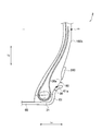
- FIG. 1 is a cross-sectional view showing a pneumatic tire 1 according to a first embodiment of the present invention.
- FIG. 2 is a partially enlarged cross-sectional view of the pneumatic tire 1 according to the first embodiment of the present invention.
- FIG. 3 is a partially enlarged sectional view of the pneumatic tire 1 according to the second embodiment of the present invention.
- FIG. 4 is a partially enlarged cross-sectional view of the pneumatic tire 1 according to the related art.
- FIG. 1 is a partial cross-sectional view showing a pneumatic tire 1 according to the present embodiment.
- FIG. 2 is a partially enlarged cross-sectional view of the pneumatic tire 1 according to the present embodiment.
- the pneumatic tire 1 includes a tread portion 10 that contacts the road surface during traveling, a tire side portion 20 that continues to the tread portion 10, and a bead portion 30 that continues to the tire side portion 20.
- the pneumatic tire 1 which concerns on this embodiment assumes the tire for heavy loads. Accordingly, in the pneumatic tire 1, the tire outer diameter OD and the rubber gauge thickness DC of the tread portion 10 are DC / OD ⁇ 0.015 in the tire circumferential direction Tc and the tire radial direction Td of the tire equator line CL. It is preferable to satisfy the relationship.
- the tire outer diameter OD (unit: mm) is the diameter of the pneumatic tire 1 at a portion (generally, the tread portion 10 near the tire equator line CL) where the outer diameter of the pneumatic tire 1 is maximum. is there.
- the rubber gauge thickness DC (unit: mm) is the rubber thickness of the tread portion 10 at the position of the tire equator line CL.
- the thickness DC of the rubber gauge does not include the thickness of the belt layer 50. That is, the thickness DC of the rubber gauge of the tread portion 10 is a length from the end portion of the belt layer 50 on the outer side in the tire radial direction Td to the tread surface on the outer side of the tread portion 10 in the tire radial direction Td.
- channel is formed in the position containing tire equator line CL, it is set as the rubber thickness of the tread part 10 in the land part adjacent to a circumferential groove
- the pneumatic tire 1 includes a carcass portion 40 that forms a skeleton of the pneumatic tire 1 and a belt layer 50 that is disposed outside the tire radial direction Td of the carcass portion 40 in the tread portion 10.
- the carcass part 40 includes a carcass cord and a layer made of rubber that covers the carcass cord.
- the carcass part 40 extends over the tread part 10, the tire side part 20, and the bead part 30.
- the carcass portion 40 includes a main body portion 41 that extends from the tread portion 10 through the tire side portion 20 to the bead core of the bead portion 30 and a folded portion 42 that is folded back by the bead core.
- an end portion 42a outside the tire radial direction Td of the folded portion 42 is the most in the tire radial direction Td. It is located in the range of 40% or more and 60% or less of the tire height H from the bead end portion 31 located on the inner side toward the outer side in the tire radial direction Td. Specifically, as shown in FIG. 1, when the length in the tire radial direction Td from the bead end portion 31 to the end portion 42a on the outer side in the tire radial direction Td of the folded portion 42 is defined as Ha, 0.4H ⁇ Ha ⁇ The relationship of 0.6H is satisfied.
- the tire height H is determined from the bead end portion 31 located at the lower end inside the tire radial direction Td in a state where the pneumatic tire 1 is assembled to the rim wheel 60.
- the length in the tire radial direction Td to the tread surface of the tread portion 10 that contacts the road surface.
- the belt layer 50 is configured by impregnating a steel cord with a rubber component.
- the belt layer 50 includes a plurality of layers, and each layer is laminated along the tire radial direction Td.
- the bead portions 30 are disposed along the tire circumferential direction Tc, and are disposed on both sides of the tire width direction Tw via the tire equator line CL. Since the pneumatic tire 1 has a line-symmetric structure with respect to the tire equator line CL, only one side is shown in FIG.
- the point on the outermost side in the tire radial direction Td where the pneumatic tire 1 contacts the rim flange 61 of the rim wheel 60 is defined as the rim separation point 61a. It prescribes.
- the state in which the pneumatic tire 1 is assembled to the rim wheel 60 means a state in which the pneumatic tire 1 is assembled to a standard rim defined in the standard with air pressure corresponding to the maximum load defined in the standard. To do. It can be said that the pneumatic tire 1 is assembled to the rim wheel 60 in a no-load state in which normal internal pressure is filled and no load is applied.
- the standard indicates JATMA YEAR BOOK (2010 edition, Japan Automobile Tire Association standard).
- the TRA standard, the ETRTO standard, or the like is applied in the place of use or manufacturing, it conforms to each standard.
- the boundary between the tread portion 10 and the tire side portion 20 is the tread end portion TE
- the boundary between the tire side portion 20 and the bead portion 30 is the rim separation point 61a.
- a rim side outer surface 80 is formed in a range up to the end portion 100a inside the direction Td.
- the rim side outer surface 80 is formed along a predetermined arc curve Rc1 having a center C1 of a curvature radius R1 inside the tire width direction Tw. That is, the rim side outer surface 80 is formed in a curved shape that swells outward in the tire width direction Tw.
- the center C1 of the curvature radius R1 is preferably located on a virtual straight line extending in the tire width direction Tw from the position of the tire maximum width portion m. Further, an end portion 100a on the inner side in the tire radial direction Td of the circumferential recess 100 is formed between an outer surface of the circumferential recess 100 and a tire outer surface (rim side outer surface 80) formed in a curved shape in the tire cross section. In other words, it can be called a boundary point.
- the circumferential recess 100 is formed in a range from the position of the tire maximum width portion m to the rim separation point 61a.
- a curve Vc1 is defined.
- the virtual arc curve Vc1 is within the range of 22% to 28% of the tire height H from the bead end portion 31.
- the depth Dx (recess depth Dx) of the circumferential recess 100 with reference to is 5 mm or more and 35 mm or less.
- the depth Dx of the circumferential recess 100 is the maximum depth within a range of 22% to 28% of the tire height H from the bead end portion 31.
- the depth of the circumferential recess 100 with respect to the virtual arc curve Vc1 is defined as a line perpendicular to the outer surface of the circumferential recess 100 with respect to the virtual arc curve Vc1. This is the distance from the point that intersects the outer surface of 100 to the point where the orthogonal line intersects the virtual arc curve Vc1.
- the depth Dx of the circumferential recess 100 (recess depth Dx) with respect to the virtual arc curve Vc1 is the tire height. 0.037% or more and 0.56% or less.
- the depth Dx of the circumferential recess 100 (recess depth Dx) based on the virtual arc curve Vc1 is the tire width. It is 0.1% or more and 1.6% or less.
- a position 100x1 is a point on the virtual arc curve Vc1 located at a height Hx1 of 22% of the tire height H from the bead end portion 31 in the tire radial direction Td.
- the position 100x0 is a point on the virtual arc curve Vc1 located at a height Hx0 that is 25% of the tire height H from the bead end portion 31 in the tire radial direction Td.
- the position 100x2 is a point on the virtual arc curve Vc1 located at a height Hx2 that is 28% of the tire height H from the bead end portion 31 in the tire radial direction Td.
- the depth Dx1 of the circumferential recessed portion 100 passes through the position 100x1 and defines an orthogonal line orthogonal to the surface (bottom surface) of the circumferential recessed portion 100, from the position 100x1 to the surface of the circumferential recessed portion 100. The distance along the orthogonal line.
- the depth Dx0 of the circumferential recess 100 is a distance along the orthogonal line from the position 100x0 to the surface of the circumferential recess 100 through the position 100x0.
- the depth Dx2 of the circumferential recess 100 is a distance along an orthogonal line from the position 100x2 to the surface of the circumferential recess 100 through the position 100x2.
- the depth Dx of the circumferential recess 100 is not less than 5 mm and not more than 35 mm within the range from the position 100x0 to the position 100x2. That is, the depth Dx1 satisfies the relationship of 5 mm ⁇ Dx1 ⁇ 35 mm, the depth Dx0 satisfies the relationship of 5 mm ⁇ Dx1 ⁇ 35 mm, and the depth Dx2 satisfies the relationship of 5 mm ⁇ Dx1 ⁇ 35 mm.
- the position 100y is a point on the virtual arc curve Vc1 located at a height Hy of 35% of the tire height H from the bead end 31 in the tire radial direction Td.
- the depth Dy of the circumferential recess 100 is a distance along the orthogonal line from the position 100y to the surface of the circumferential recess 100 when the orthogonal line passing through the position 100y and orthogonal to the outer surface of the circumferential recess 100 is defined. It is.
- the depth of the circumferential recess 100 based on the virtual arc curve Vc1 is the largest in the region of 25% or more and 35% or less of the tire height H from the bead end 31 in the tire cross section in the no-load state.
- the difference between the deepest deepest part and the shallowest part with the shallowest depth of the circumferential recess 100 with reference to the virtual arc curve Vc1 is 15 mm or less.
- the position 100x0 of 25% of the tire height is the deepest portion, and the tire height of 35 % Position 100y is the shallowest part. Therefore, the maximum depth Dx of the circumferential recess 100 and the minimum depth Dy of the circumferential recess 100 satisfy the relationship Dx ⁇ Dy ⁇ 15 mm.
- the depth of the circumferential recess 100 with respect to the thickness Da of the rubber located on the tire surface side with respect to the carcass portion within a range of 22% to 28% of the tire height H from the bead end portion 31.
- the ratio is 1.5 or more and 30 or less.
- the thickness Da of the rubber positioned on the tire surface side with respect to the carcass portion is defined by defining a straight line FL1 perpendicular to the bottom surface of the circumferential recess 100 and extending to the main body portion of the carcass portion in the cross-sectional view shown in FIG. The distance between the intersection point P1 between the straight line and the bottom surface of the circumferential recess and the intersection point P2 between the straight line and the carcass portion.
- the thickness of the circumferential recess 100 to the thickness Da of the rubber positioned on the tire surface side from the carcass is less than 1.5, the thickness of the circumferential recess contributing to cooling and the thickness to be cooled There is little difference in (thickness from the carcass portion to the outer surface of the tire (the bottom surface of the circumferential recess)), and the tire cooling effect by the circumferential recess cannot be greatly obtained.
- the thickness from the carcass portion to the tire outer surface becomes too thin, and the carcass portion There is a risk of distortion.
- the bending of the tire side during traveling tends to be large, and thus the bending of the carcass portion may occur due to the inability to withstand the bending.
- the side wall surface 101 formed in the range from the end portion 100a on the inner side in the tire radial direction Td of the circumferential recess 100 to the deepest portion (bottom surface) of the circumferential recess 100 is curved outward in the tire width direction. It is formed along a circular arc curve Rc2 having a radius center. That is, the side wall surface 101 is formed in a curved surface shape.
- the side wall surface 101 is a wall surface between the end portion 100a on the inner side in the tire radial direction Td of the circumferential recess 100 and the bottom surface.
- the curvature radius of the bottom surface is larger than the curvature radius of the arcuate curve Rc2 on the side wall surface.
- the boundary between the bottom surface and the side wall surface is where the radius of curvature changes.
- the side wall surface 101 is provided at a position within a predetermined range from the rim separation point 61a toward the outside in the tire radial direction Td. Specifically, the side wall surface 101 is outside the tire radial direction Td from the rim separation point 61a that is the outermost point in the tire radial direction Td in contact with the rim flange 61, and is outside the tire radial direction Td from the rim separation point 61a. It is preferable that it is located within the range of less than 25% of the tire height H.
- the outer surface of the tire side portion 20 is formed with a circumferential recess 100 that is recessed in the tire width direction Tw and that extends in the tire circumferential direction Tc. Yes.
- the depth Dx of the circumferential recess 100 based on the virtual arc curve Vc1 is within a range of 5 mm to 35 mm within a range of 22% to 28% of the tire height H from the bead end 31. It is.
- the depth Dx is less than 5 mm within the range of 22% or more and 28% or less of the tire height H, the high temperature portion and the heat radiation surface (the surface of the circumferential recess 100) inside the tire (particularly the inside on the bead 30 side) Therefore, the effect of suppressing the temperature rise of the rubber cannot be sufficiently obtained.
- the depth Dx is larger than 35 mm, the amount of collapse of the carcass portion 40 increases when shifting from no load to load. Thereby, the shear strain between the main body portion 41 and the folded portion 42 is deteriorated, a crack is generated between the main body portion and the folded portion, and as a result, the inside of the tire side portion may be damaged. .
- the depth Dx of the circumferential recess 100 based on the virtual arc curve Vc1 is within the range of 22% to 28% of the tire height H from the bead end portion 31.
- the volume of the rubber used for the tire side portion 20 is compared with the case where the circumferential recess 100 is not formed because the circumferential recess 100 is formed. Is reduced. For this reason, it is possible to suppress heat generation due to deformation of the rubber of the tire side portion 20. Furthermore, since the rubber amount for manufacturing the pneumatic tire 1 can be reduced, the manufacturing cost of the pneumatic tire 1 can be suppressed.
- the side wall surface 101 extending from the end portion 100a on the inner side in the tire radial direction Td of the circumferential recess 100 to the deepest portion of the circumferential recess 100 is along an arc curve Rc2 having a center C2 of a curvature radius R2 outside the tire width direction Tw. Formed. That is, in the circumferential recessed portion 100, the end portion 100a on the inner side in the tire radial direction Td to the deepest portion is formed to be recessed with a curved surface shape.
- the air flowing along the tire side portion 20 easily flows smoothly into the circumferential recess 100 along the curved side wall surface 101 due to the rotation of the tire.
- the air inside the circumferential recess 100 is easily discharged to the outside. That is, it is possible to increase the amount of air circulating inside the circumferential recess 100 and suppress the temperature rise of the rubber.
- the curvature radius R2 of the circular arc formed by the side wall surface 101 in the cross section along the tire width direction Tw and the tire radial direction Td of the pneumatic tire 1 is 50 mm or more in a no-load state.
- the curvature radius R2 of the side wall surface 101 is less than 50 mm, the distortion of the side wall surface 101 caused by the collapse of the tire side portion 20 at the time of load is locally concentrated, and the bead portion 30 side of the tire side portion 20 is This is because the crack resistance may be deteriorated.
- the curvature radius Ra of the side wall surface 101 in the no-load state where there is no load and the side wall surface 101 in the normal load state in which the normal internal pressure is filled and the normal load is applied.
- the curvature radius Rb may satisfy the relationship of (Ra ⁇ Rb) /Ra ⁇ 0.5.
- an outer wall surface (not shown) positioned on the outer side in the tire radial direction Td of the circumferential recess 100 may be formed along an arc curve having a center of curvature radius on the outer side in the tire width direction Tw. That is, in the circumferential recessed part 100, the outer end part 100b in the tire radial direction Td to the deepest part may be formed so as to be recessed by a curved surface shape.
- the circumference based on the virtual arc curve Vc1 is used in a tire cross section in a no-load state.
- the difference between the deepest portion of the directional recess 100 and the shallowest portion of the circumferential recess 100 on the basis of the virtual arc curve Vc1 is 15 mm or less. If the difference between the shallowest part and the deepest part is larger than 15 mm, the tire mold is formed into an excessively convex shape (the tire shape is concave), and thus manufacturing defects such as bears when the pneumatic tire 1 is manufactured. Is likely to occur. For this reason, generation
- the side wall surface 101 of the circumferential recess 100 is outside the tire radial direction Td with respect to the rim separation point 61a, which is the outermost point in the tire radial direction Td in contact with the rim flange 61, and the rim separation. It is preferable that the position is within a range of less than 25% of the tire height H from the point 61a toward the outside in the tire radial direction Td.
- the carcass portion 40 is greatly collapsed during loading. It is possible to suppress the temperature rise without deteriorating. If it is provided below the rim separation point 61a, the fall of the carcass part 40 under load increases, and the durability of the bead part 30 is significantly deteriorated.
- the side wall surface 101 within a range of less than 25% of the tire height H from the rim separation point 61a, the distance from the high temperature region inside the tire to the surface of the circumferential recess 100 that is a heat radiating surface can be reduced. The effect of suppressing the temperature rise can be obtained. If the cross-sectional height is higher than 25%, the distance from the high temperature region inside the tire to the tire surface (side wall surface 101) that is the heat radiating surface cannot be shortened. It becomes difficult to obtain enough.
- FIG. 3 is a partially enlarged plan view of the circumferential recess 100 according to the second embodiment.
- blocks 200 protruding outward in the tire width direction Tw are formed in the circumferential recess 100 with a predetermined pitch in the tire circumferential direction.
- a part of the block 200 is disposed in the region of the side wall surface 101.
- the block 200 may be disposed outside the region of the side wall surface 101.
- the air that smoothly flows along the curved side wall surface 101 collides with the block 200, whereby the air that flows as turbulent flow inside the circumferential recess 100. Can be active.
- the height h of the block 200 is preferably in the range of 7.5 mm to 25 mm. According to such a pneumatic tire 2, even when the pneumatic tire 2 is used in any speed range in a practical speed range of a construction vehicle tire, it is possible to exert an effect of suppressing an increase in rubber temperature. it can.
- the width w of the block 200 in the tire circumferential direction Tc is preferably formed within a range of 2 mm to 10 mm.
- the block 200 may be vibrated by the air flow drawn into the circumferential recess 100.
- the width W in the tire circumferential direction Tc of the block 200 is less than 2 mm, the rigidity of each block may be reduced, which may cause damage due to running on a rough road.
- the width w in the tire circumferential direction Tc of the block 200 is larger than 10 mm, the amount of rubber forming each block is increased, so that heat is easily generated. Therefore, the effect of suppressing the temperature rise due to the formation of the circumferential recess 100 is reduced.
- a plurality of blocks 200 are provided at predetermined pitches in the tire circumferential direction Tc.
- the height h of the block 200, the predetermined pitch p in the tire circumferential direction of the block 200, and the width w of the block 200 are 1.0 ⁇ p / h ⁇ 50.0 and 1.0 ⁇ (p ⁇ w). ) /W ⁇ 100.0.
- a part of the block 200 is formed so as to protrude outward in the tire width direction Tw by a predetermined protruding height from the virtual arc curve Vc1.
- the air flowing along the outer surface of the tire side portion 20 collides with the protruding portion of the block 200 and easily flows into the circumferential recess 100. That is, it is possible to increase the amount of air that flows into the circumferential recess 100 to suppress the temperature rise of the rubber.
- the block 200 has an integrated shape extending in the tire radial direction Td has been described as an example.
- the block 200 may be divided into a plurality of pieces in the tire radial direction Td. .
- Evaluation method A test was performed using a plurality of types of pneumatic tires, and the effect of suppressing the temperature rise of the tires and the amount of distortion in the carcass portion 40 were evaluated.
- the outer surface of the tire side portion of the tire cross section has a shape along the virtual arc curve Vc1.
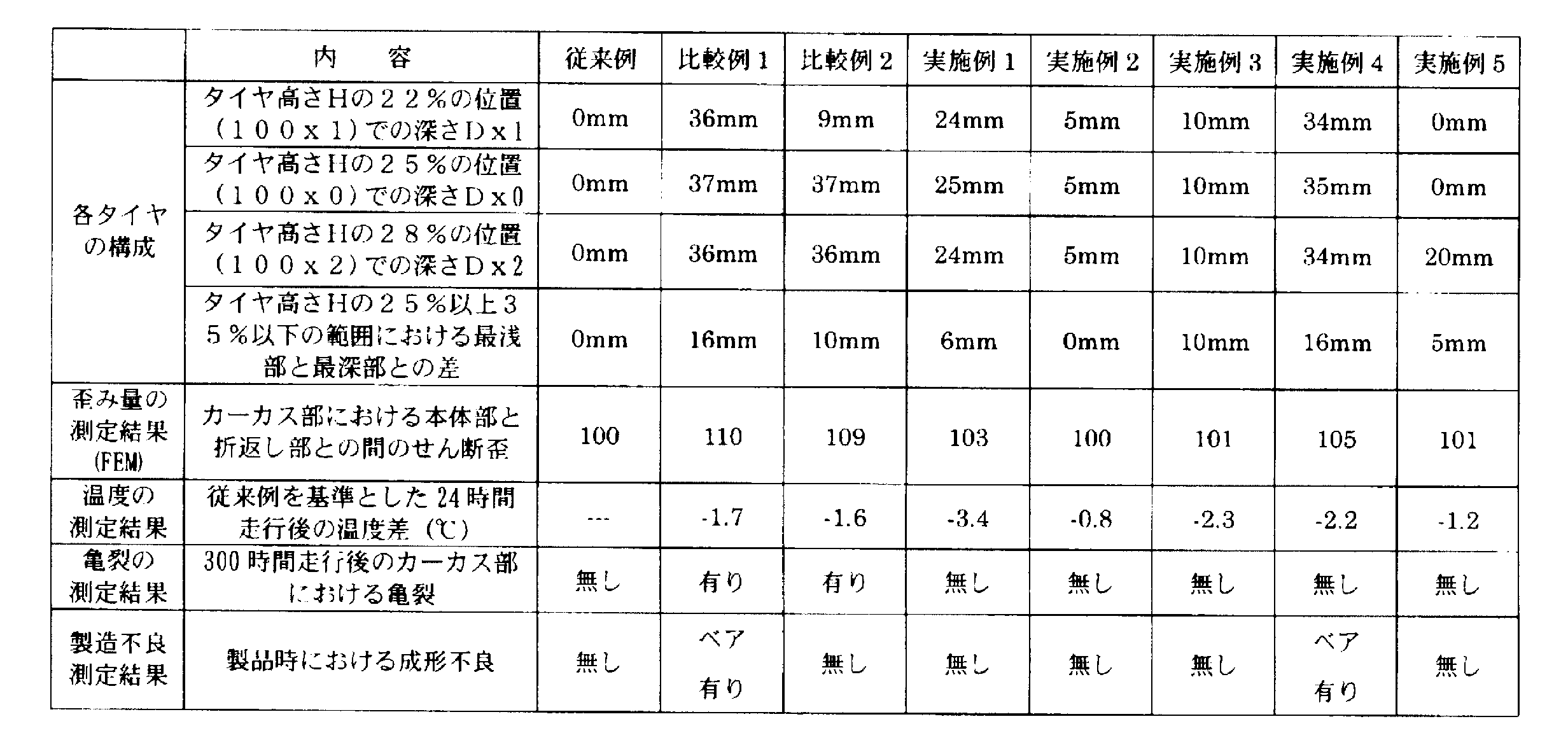
- the pneumatic tires according to Comparative Examples 1 and 2 and Examples 1 to 5 were pneumatic tires in which circumferential recesses were formed in the tire side portions.
- the detailed configurations of Comparative Examples 1 and 2 and Examples 1 to 5 are as shown in Table 1.
- the tire size of each tire was 59 / 80R63.
- ⁇ Strain evaluation test> About the distortion amount evaluation test, the amount of distortion generated between the main body portion and the folded portion in the carcass portion of each tire was evaluated by performing simulation by a finite element method (FEM) analysis. Specifically, each tire was assembled on a standard rim (conforming to TRA), and the normal inner pressure (conforming to TRA) and normal load (conforming to TRA) were applied, and the strain during flat pushing was calculated on a planar model. .
- the measurement results shown in Table 1 represent the values when the tire distortion amount according to the conventional example is used as a reference (100) by an index. In addition, it shows that the amount of distortion is small and excellent, so that this numerical value is small.
- ⁇ Temperature evaluation test> For the temperature evaluation test, each tire was assembled on a standard rim (compliant with TRA), and after rolling on a drum testing machine under a normal internal pressure (compliant with TRA) and regular load (compliant with TRA). The temperature of the bead portion was measured. Specifically, after running for 24 hours at a speed of 8 km / h, the temperature of the bead portion was measured. The measurement results shown in Table 1 represent the difference value of each tire based on the temperature according to the conventional example. This value indicates that the larger the value in the minus ( ⁇ ) direction, the better the effect of suppressing the temperature rise.
- the embodiment of the present invention has been described by taking as an example the case where the pneumatic tire 1 is a heavy load tire, other tires such as a passenger tire may be used.
- the tire may be a pneumatic tire filled with air or nitrogen gas, or a solid tire not filled with air or nitrogen gas.
- the tire according to the present invention can provide a tire capable of achieving both suppression of a temperature rise on the tire side portion, particularly the bead portion side, and suppression of tire damage.
Abstract
Description
まず、本発明の第1実施形態について説明する。 [First Embodiment]
First, a first embodiment of the present invention will be described.
本実施形態に係る空気入りタイヤ1は、ダンプトラックなどの建設車両に装着される重荷重用の空気入りタイヤ(重荷重用タイヤ)である。空気入りタイヤ1の構成について、図面を参照しながら説明する。図1は、本実施形態に係る空気入りタイヤ1を示す一部断面図である。図2は、本実施形態に係る空気入りタイヤ1の一部拡大断面図である。 (1) Configuration of Pneumatic Tire 1 The
次に、周方向凹部100の構成について具体的に説明する。周方向凹部100は、タイヤ最大幅部mの位置からリム離反点61aまでの範囲に形成される。 (2) Configuration of the
本実施形態に係る空気入りタイヤ1では、タイヤサイド部20の外表面には、タイヤ幅方向Tw内側に凹むとともに、タイヤ周方向Tcに延びる周方向凹部100が形成されている。 (5) Action / Effect In the
次に、本発明の第2実施形態に係る空気入りタイヤ2について説明する。なお、第1実施形態と同一の構成については、詳細な説明を適宜省略する。図3は、第2実施形態に係る周方向凹部100の一部拡大平面図である。 [Second Embodiment]
Next, a
次に、本発明の効果を更に明確にするために、以下の従来例、比較例及び実施例に係る空気入りタイヤを用いて行った比較評価について説明する。なお、本発明はこれらの例によって何ら限定されるものではない。 [Comparison evaluation]
Next, in order to further clarify the effects of the present invention, a comparative evaluation performed using pneumatic tires according to the following conventional examples, comparative examples, and examples will be described. In addition, this invention is not limited at all by these examples.
複数種類の空気入りタイヤを用いて試験を行い、タイヤの温度上昇を抑制する効果とカーカス部40における歪み量とについて評価をした。 (1) Evaluation method A test was performed using a plurality of types of pneumatic tires, and the effect of suppressing the temperature rise of the tires and the amount of distortion in the
歪み量評価試験については、有限要素法(FEM:Finite Element Method)解析によりシミュレーションを行うことで、各タイヤのカーカス部において、本体部と折返し部との間に発生する歪み量を評価した。具体的に、各タイヤを標準リム(TRAに準拠)に組み付け、正規内圧(TRAに準拠)、正規荷重(TRAに準拠)を与えた状態において、平面モデル上で平押し時の歪を計算した。表1に示される測定結果は、従来例に係るタイヤの歪み量を基準(100)としたときの値を、指数によって表している。なお、この数値が小さいほど、歪み量が小さく、優れていることを示す。 <Strain evaluation test>
About the distortion amount evaluation test, the amount of distortion generated between the main body portion and the folded portion in the carcass portion of each tire was evaluated by performing simulation by a finite element method (FEM) analysis. Specifically, each tire was assembled on a standard rim (conforming to TRA), and the normal inner pressure (conforming to TRA) and normal load (conforming to TRA) were applied, and the strain during flat pushing was calculated on a planar model. . The measurement results shown in Table 1 represent the values when the tire distortion amount according to the conventional example is used as a reference (100) by an index. In addition, it shows that the amount of distortion is small and excellent, so that this numerical value is small.
温度評価試験については、各タイヤを標準リム(TRAに準拠)に組み付け、正規内圧(TRAに準拠)、正規荷重(TRAに準拠)を与えた状態において、ドラム試験機上で転動させた後に、ビード部の温度を測定した。具体的に、速度8km/hによって、24時間走行させた後に、ビード部の温度を測定した。表1に示される測定結果は、従来例に係る温度を基準にし、各タイヤの差の値を表している。なお、この値は、マイナス(-)方向における値が大きいほど、温度上昇を抑制する効果に優れていることを示す。 <Temperature evaluation test>
For the temperature evaluation test, each tire was assembled on a standard rim (compliant with TRA), and after rolling on a drum testing machine under a normal internal pressure (compliant with TRA) and regular load (compliant with TRA). The temperature of the bead portion was measured. Specifically, after running for 24 hours at a speed of 8 km / h, the temperature of the bead portion was measured. The measurement results shown in Table 1 represent the difference value of each tire based on the temperature according to the conventional example. This value indicates that the larger the value in the minus (−) direction, the better the effect of suppressing the temperature rise.
亀裂評価試験については、上述した温度評価試験を実施した後、正規内圧(TRAに準拠)の180%に荷重を高めて、更に300時間走行させた。この後に、各タイヤを切断し、カーカス部における本体部と折返し部との間に亀裂が発生しているか否かを確認した。 <Crack evaluation test>
Regarding the crack evaluation test, after the temperature evaluation test described above was performed, the load was increased to 180% of the normal internal pressure (based on TRA), and the test was further run for 300 hours. Thereafter, each tire was cut, and it was confirmed whether or not a crack occurred between the main body portion and the folded portion in the carcass portion.
製造不良試験については、各タイヤを製造する際に、ベアが発生しているか否かを確認した。 <Manufacturing failure evaluation test>
About the manufacture defect test, when manufacturing each tire, it was confirmed whether the bear has generate | occur | produced.
各空気入りタイヤの評価結果について、表1を参照しながら説明する。
上述したように、本発明の実施形態を通じて本発明の内容を開示したが、この開示の一部をなす論述及び図面は、本発明を限定するものであると理解すべきではない。この開示から当業者には様々な代替実施の形態、実施例及び運用技術が明らかとなる。 [Other Embodiments]
Although the contents of the present invention have been disclosed through the embodiments of the present invention as described above, it should not be understood that the descriptions and drawings constituting a part of this disclosure limit the present invention. From this disclosure, various alternative embodiments, examples, and operational techniques will be apparent to those skilled in the art.
Claims (8)
- 路面と接するトレッド部と、前記トレッド部に連なるタイヤサイド部と、前記タイヤサイド部に連なるビード部とを有するとともに、トレッド部とタイヤサイド部とビード部とにわたって延びるカーカス部を有するタイヤであって、
前記カーカス部は、トレッド部からタイヤサイド部をへてビード部のビードコアに至る本体部と、前記ビードコアで折り返す折返し部とを有し、
前記タイヤサイド部の外表面には、タイヤ幅方向内側に凹むとともに、タイヤ周方向に延びる周方向凹部が形成されており、
タイヤ幅方向及びタイヤ径方向に沿ったタイヤ断面において、リムフランジと接するリム離反点から前記周方向凹部のタイヤ径方向内側の端部までの範囲に形成されるリム側外表面は、タイヤ幅方向内側に曲率半径の中心を有する所定の円弧曲線に沿って形成されており、
前記タイヤ断面において、前記所定の円弧曲線を延長させた仮想円弧曲線を規定した場合、前記仮想円弧曲線を基準とした前記周方向凹部の深さは、ビード端部からタイヤ高さの22%以上28%以下の範囲内において、5mm以上35mm以下であることを特徴とするタイヤ。 A tire having a tread portion in contact with a road surface, a tire side portion continuous with the tread portion, a bead portion continuous with the tire side portion, and a carcass portion extending over the tread portion, the tire side portion, and the bead portion. ,
The carcass part has a main body part extending from the tread part to the tire side part to the bead core of the bead part, and a folded part turned back by the bead core,
On the outer surface of the tire side portion, a recess in the tire width direction is recessed and a circumferential recess extending in the tire circumferential direction is formed.
In the tire cross section along the tire width direction and the tire radial direction, the rim side outer surface formed in the range from the rim separation point in contact with the rim flange to the inner end in the tire radial direction of the circumferential recess is the tire width direction. It is formed along a predetermined arc curve having a center of curvature radius on the inside,
In the tire cross section, when a virtual arc curve obtained by extending the predetermined arc curve is defined, the depth of the circumferential recess based on the virtual arc curve is 22% or more of the tire height from the bead end. A tire characterized by being 5 mm or more and 35 mm or less within a range of 28% or less. - 前記タイヤ断面において、前記周方向凹部のタイヤ径方向内側の端部から、前記仮想円弧曲線を基準とした前記周方向凹部の深さが最も深い最深部までの範囲に形成される側壁面は、タイヤ幅方向外側に曲率半径の中心を有する円弧曲線に沿って形成されている
ことを特徴とする請求項1に記載のタイヤ。 In the tire cross section, the side wall surface formed in the range from the end portion in the tire radial direction of the circumferential recess to the deepest depth of the circumferential recess with reference to the virtual arc curve, 2. The tire according to claim 1, wherein the tire is formed along an arcuate curve having a center of curvature radius on the outer side in the tire width direction. - 前記タイヤ断面において、前記側壁面によって形成される円弧曲線の曲率半径は、50mm以上である
ことを特徴とする請求項2に記載のタイヤ。 3. The tire according to claim 2, wherein a radius of curvature of an arc curve formed by the side wall surface in the tire cross section is 50 mm or more. - 前記タイヤ断面において、前記側壁面は、前記リム離反点よりもタイヤ径方向外側であり、前記リム離反点からタイヤ径方向外側に向かって前記タイヤ高さの25%未満の範囲内に位置する
ことを特徴とする請求項2又は3に記載のタイヤ。 In the tire cross section, the side wall surface is located on the outer side in the tire radial direction from the rim separation point, and is located within a range of less than 25% of the tire height from the rim separation point toward the outer side in the tire radial direction. The tire according to claim 2 or 3, wherein - 前記タイヤ断面において、前記ビード端部からタイヤ高さの25%以上35%以下の領域では、前記仮想円弧曲線を基準とした前記周方向凹部の深さが最も深い最深部と、前記仮想円弧曲線を基準とした前記周方向凹部の深さが最も浅い最浅部との差は、15mm以下である
ことを特徴とする請求項1乃至4の何れか一項に記載のタイヤ。 In the tire cross section, in the region of 25% or more and 35% or less of the tire height from the bead end, the deepest portion where the depth of the circumferential recess is the deepest with respect to the virtual arc curve, and the virtual arc curve The tire according to any one of claims 1 to 4, wherein a difference from the shallowest portion where the depth of the circumferential concave portion is the shallowest is 15 mm or less. - 正規内圧を充填し、無荷重である無荷重状態における前記タイヤ断面において、前記折り返し部のタイヤ径方向外側の端部は、タイヤ径方向の最も内側に位置するビード端部から、タイヤ径方向外側に向かってタイヤ高さの40%以上60%以下の範囲に位置する
ことを特徴とする請求項1乃至5の何れか一項に記載のタイヤ。 In the tire cross section in a no-load state in which normal internal pressure is filled and there is no load, the end portion on the outer side in the tire radial direction of the folded portion is the outer side in the tire radial direction from the bead end portion located on the innermost side in the tire radial direction The tire according to any one of claims 1 to 5, wherein the tire is located in a range of 40% or more and 60% or less of the tire height. - 前記周方向凹部の内部には、タイヤ幅方向外側に向かって突出するブロックが、タイヤ周方向に所定ピッチを設けて形成されている
ことを特徴とする請求項1乃至6の何れか一項に記載のタイヤ。 The block which protrudes toward the tire width direction outer side is provided in the inside of the said circumferential direction recessed part, providing the predetermined pitch in the tire circumferential direction, The Claim 1 thru | or 6 characterized by the above-mentioned. The described tire. - 前記ビード端部からタイヤ高さの22%以上28%以下の範囲内において、前記カーカス部よりもタイヤ表面側に位置するゴムの厚みに対する、前記周方向凹部の深さの比率は、1.5以上30以下である、請求項1乃至7の何れか一項に記載のタイヤ。 In the range of 22% to 28% of the tire height from the bead end, the ratio of the depth of the circumferential recess to the thickness of the rubber located on the tire surface side of the carcass is 1.5. The tire according to any one of claims 1 to 7, wherein the tire is 30 or less.
Priority Applications (8)
| Application Number | Priority Date | Filing Date | Title |
|---|---|---|---|
| ES14754677.4T ES2638417T3 (en) | 2013-02-22 | 2014-02-21 | Tire |
| CA2880939A CA2880939C (en) | 2013-02-22 | 2014-02-21 | Tire |
| BR112015002147-6A BR112015002147B1 (en) | 2013-02-22 | 2014-02-21 | TIRE FOR HEAVY LOADS |
| AU2014219729A AU2014219729B2 (en) | 2013-02-22 | 2014-02-21 | Tyre |
| CN201480002011.1A CN104507710B (en) | 2013-02-22 | 2014-02-21 | Tire |
| EP14754677.4A EP2873539B1 (en) | 2013-02-22 | 2014-02-21 | Tire |
| RU2015103067/11A RU2581280C1 (en) | 2013-02-22 | 2014-02-21 | Tyre |
| US14/415,913 US10226969B2 (en) | 2013-02-22 | 2014-02-21 | Heavy load tire with curved sidewall recess |
Applications Claiming Priority (2)
| Application Number | Priority Date | Filing Date | Title |
|---|---|---|---|
| JP2013-033450 | 2013-02-22 | ||
| JP2013033450A JP5545901B1 (en) | 2013-02-22 | 2013-02-22 | tire |
Publications (1)
| Publication Number | Publication Date |
|---|---|
| WO2014129571A1 true WO2014129571A1 (en) | 2014-08-28 |
Family
ID=51391352
Family Applications (1)
| Application Number | Title | Priority Date | Filing Date |
|---|---|---|---|
| PCT/JP2014/054122 WO2014129571A1 (en) | 2013-02-22 | 2014-02-21 | Tire |
Country Status (11)
| Country | Link |
|---|---|
| US (1) | US10226969B2 (en) |
| EP (1) | EP2873539B1 (en) |
| JP (1) | JP5545901B1 (en) |
| CN (1) | CN104507710B (en) |
| AU (1) | AU2014219729B2 (en) |
| BR (1) | BR112015002147B1 (en) |
| CA (1) | CA2880939C (en) |
| CL (1) | CL2015000176A1 (en) |
| ES (1) | ES2638417T3 (en) |
| RU (1) | RU2581280C1 (en) |
| WO (1) | WO2014129571A1 (en) |
Cited By (2)
| Publication number | Priority date | Publication date | Assignee | Title |
|---|---|---|---|---|
| EP3231640A4 (en) * | 2014-12-10 | 2017-11-22 | Bridgestone Corporation | Tire for construction vehicle |
| WO2018110668A1 (en) * | 2016-12-15 | 2018-06-21 | 横浜ゴム株式会社 | Pneumatic tire |
Families Citing this family (8)
| Publication number | Priority date | Publication date | Assignee | Title |
|---|---|---|---|---|
| JP6665530B2 (en) * | 2015-12-25 | 2020-03-13 | 横浜ゴム株式会社 | Pneumatic tire |
| EP3345776A1 (en) * | 2016-12-27 | 2018-07-11 | Hankook Tire Co., Ltd. | Pneumatic tire |
| JP6311810B1 (en) * | 2017-02-28 | 2018-04-18 | 横浜ゴム株式会社 | Pneumatic tire |
| JP6935365B2 (en) | 2018-06-21 | 2021-09-15 | 株式会社ブリヂストン | Tires for construction vehicles |
| JP7183689B2 (en) * | 2018-10-22 | 2022-12-06 | 住友ゴム工業株式会社 | Heavy duty pneumatic tire |
| JP7131395B2 (en) * | 2019-01-07 | 2022-09-06 | 横浜ゴム株式会社 | pneumatic tire |
| US20220153068A1 (en) | 2020-11-18 | 2022-05-19 | The Goodyear Tire & Rubber Company | Radial tire |
| CN112848808B (en) * | 2021-01-29 | 2023-09-29 | 山东玲珑轮胎股份有限公司 | Tire with a tire cover |
Citations (5)
| Publication number | Priority date | Publication date | Assignee | Title |
|---|---|---|---|---|
| JPH0632122A (en) * | 1992-07-14 | 1994-02-08 | Bridgestone Corp | Pneumatic tire |
| JPH10193924A (en) * | 1997-01-09 | 1998-07-28 | Sumitomo Rubber Ind Ltd | Pneumatic tire |
| JP2000158919A (en) * | 1998-11-24 | 2000-06-13 | Bridgestone Corp | Pneumatic tire |
| JP2010111370A (en) | 2008-10-09 | 2010-05-20 | Bridgestone Corp | Pneumatic tire |
| WO2012018128A1 (en) * | 2010-08-05 | 2012-02-09 | 株式会社ブリヂストン | Tire |
Family Cites Families (15)
| Publication number | Priority date | Publication date | Assignee | Title |
|---|---|---|---|---|
| FR2415016A1 (en) * | 1978-01-20 | 1979-08-17 | Michelin & Cie | Partially concave sidewall profiles for tubeless tyres - to enhance radial flexibility and hench ride comfort |
| JPS57191104A (en) * | 1981-05-17 | 1982-11-24 | Toyo Tire & Rubber Co Ltd | Radial tire for truck and bus |
| JP2983606B2 (en) * | 1990-10-16 | 1999-11-29 | 株式会社ブリヂストン | Pneumatic tire |
| JPH04215508A (en) * | 1990-12-12 | 1992-08-06 | Yokohama Rubber Co Ltd:The | Pneumatic radial tire |
| JPH05155205A (en) * | 1991-12-04 | 1993-06-22 | Bridgestone Corp | Pneumatic tire for heavy load |
| JP3209449B2 (en) * | 1992-05-18 | 2001-09-17 | 株式会社ブリヂストン | Pneumatic tire |
| US5429168A (en) * | 1993-11-16 | 1995-07-04 | The Goodyear Tire & Rubber Company | Off-the-road pneumatic tire with specified bead area design |
| JP3504733B2 (en) * | 1994-08-04 | 2004-03-08 | 株式会社ブリヂストン | Pneumatic radial tire for heavy loads |
| JP3568321B2 (en) * | 1996-07-22 | 2004-09-22 | 横浜ゴム株式会社 | Pneumatic tire and mold for molding the tire |
| ID20252A (en) | 1997-01-09 | 1998-11-12 | Sumitomo Rubber Ind | PNEUMATIC TIRE |
| US7234495B2 (en) * | 2004-12-15 | 2007-06-26 | The Goodyear Tire & Rubber Company | Underground mine tire |
| JP4748779B2 (en) * | 2005-08-02 | 2011-08-17 | 東洋ゴム工業株式会社 | Pneumatic tire |
| ES2616804T3 (en) * | 2010-08-05 | 2017-06-14 | Bridgestone Corporation | Tire |
| JP2013035348A (en) * | 2011-08-04 | 2013-02-21 | Sumitomo Rubber Ind Ltd | Pneumatic tire |
| JP5775007B2 (en) * | 2012-01-27 | 2015-09-09 | 株式会社ブリヂストン | tire |
-
2013
- 2013-02-22 JP JP2013033450A patent/JP5545901B1/en active Active
-
2014
- 2014-02-21 BR BR112015002147-6A patent/BR112015002147B1/en active IP Right Grant
- 2014-02-21 EP EP14754677.4A patent/EP2873539B1/en not_active Not-in-force
- 2014-02-21 WO PCT/JP2014/054122 patent/WO2014129571A1/en active Application Filing
- 2014-02-21 CA CA2880939A patent/CA2880939C/en active Active
- 2014-02-21 US US14/415,913 patent/US10226969B2/en not_active Expired - Fee Related
- 2014-02-21 RU RU2015103067/11A patent/RU2581280C1/en active
- 2014-02-21 ES ES14754677.4T patent/ES2638417T3/en active Active
- 2014-02-21 CN CN201480002011.1A patent/CN104507710B/en not_active Expired - Fee Related
- 2014-02-21 AU AU2014219729A patent/AU2014219729B2/en not_active Ceased
-
2015
- 2015-01-23 CL CL2015000176A patent/CL2015000176A1/en unknown
Patent Citations (5)
| Publication number | Priority date | Publication date | Assignee | Title |
|---|---|---|---|---|
| JPH0632122A (en) * | 1992-07-14 | 1994-02-08 | Bridgestone Corp | Pneumatic tire |
| JPH10193924A (en) * | 1997-01-09 | 1998-07-28 | Sumitomo Rubber Ind Ltd | Pneumatic tire |
| JP2000158919A (en) * | 1998-11-24 | 2000-06-13 | Bridgestone Corp | Pneumatic tire |
| JP2010111370A (en) | 2008-10-09 | 2010-05-20 | Bridgestone Corp | Pneumatic tire |
| WO2012018128A1 (en) * | 2010-08-05 | 2012-02-09 | 株式会社ブリヂストン | Tire |
Non-Patent Citations (1)
| Title |
|---|
| See also references of EP2873539A4 * |
Cited By (3)
| Publication number | Priority date | Publication date | Assignee | Title |
|---|---|---|---|---|
| EP3231640A4 (en) * | 2014-12-10 | 2017-11-22 | Bridgestone Corporation | Tire for construction vehicle |
| WO2018110668A1 (en) * | 2016-12-15 | 2018-06-21 | 横浜ゴム株式会社 | Pneumatic tire |
| JP6418339B1 (en) * | 2016-12-15 | 2018-11-07 | 横浜ゴム株式会社 | Pneumatic tire |
Also Published As
| Publication number | Publication date |
|---|---|
| EP2873539B1 (en) | 2017-06-07 |
| JP5545901B1 (en) | 2014-07-09 |
| AU2014219729B2 (en) | 2015-06-18 |
| CN104507710A (en) | 2015-04-08 |
| JP2014162299A (en) | 2014-09-08 |
| CA2880939A1 (en) | 2014-08-28 |
| CA2880939C (en) | 2017-05-02 |
| AU2014219729A1 (en) | 2015-02-19 |
| CL2015000176A1 (en) | 2015-08-07 |
| US10226969B2 (en) | 2019-03-12 |
| BR112015002147A2 (en) | 2019-10-15 |
| RU2581280C1 (en) | 2016-04-20 |
| US20150231934A1 (en) | 2015-08-20 |
| EP2873539A1 (en) | 2015-05-20 |
| CN104507710B (en) | 2016-05-04 |
| BR112015002147B1 (en) | 2021-08-10 |
| EP2873539A4 (en) | 2016-03-02 |
| ES2638417T3 (en) | 2017-10-20 |
Similar Documents
| Publication | Publication Date | Title |
|---|---|---|
| WO2014129571A1 (en) | Tire | |
| JP5144721B2 (en) | Heavy duty radial tire | |
| JP5956942B2 (en) | tire | |
| RU2618358C2 (en) | Pneumatic tire | |
| JP2015067256A (en) | Pneumatic tire | |
| JP5791427B2 (en) | Heavy duty pneumatic tire | |
| CA3001116A1 (en) | Pneumatic tire | |
| JP6121285B2 (en) | Pneumatic tire | |
| JP4843661B2 (en) | Heavy duty tire | |
| JP4555873B2 (en) | Heavy duty tire | |
| JP5997533B2 (en) | Pneumatic radial tire | |
| WO2015019995A1 (en) | Pneumatic tire | |
| JP6610147B2 (en) | Pneumatic tire | |
| WO2020170537A1 (en) | Pneumatic tire | |
| JP2011068349A (en) | Heavy-duty tire | |
| JP6010987B2 (en) | Pneumatic tire | |
| JP6411007B2 (en) | Pneumatic tire | |
| JP2017071278A (en) | Pneumatic tire | |
| JP6437879B2 (en) | Radial tires for construction vehicles | |
| JP2014136444A (en) | Tire | |
| JP6489917B2 (en) | Pneumatic tire | |
| JP6627519B2 (en) | Pneumatic tire | |
| JP6075954B2 (en) | Pneumatic radial tire | |
| JP6501600B2 (en) | Pneumatic tire | |
| JP6009748B2 (en) | Pneumatic tire |
Legal Events
| Date | Code | Title | Description |
|---|---|---|---|
| WWE | Wipo information: entry into national phase |
Ref document number: 201480002011.1 Country of ref document: CN |
|
| 121 | Ep: the epo has been informed by wipo that ep was designated in this application |
Ref document number: 14754677 Country of ref document: EP Kind code of ref document: A1 |
|
| WWE | Wipo information: entry into national phase |
Ref document number: 14415913 Country of ref document: US |
|
| REEP | Request for entry into the european phase |
Ref document number: 2014754677 Country of ref document: EP |
|
| WWE | Wipo information: entry into national phase |
Ref document number: 2014754677 Country of ref document: EP |
|
| ENP | Entry into the national phase |
Ref document number: 2880939 Country of ref document: CA Ref document number: 2015103067 Country of ref document: RU Kind code of ref document: A |
|
| ENP | Entry into the national phase |
Ref document number: 2014219729 Country of ref document: AU Date of ref document: 20140221 Kind code of ref document: A |
|
| REG | Reference to national code |
Ref country code: BR Ref legal event code: B01A Ref document number: 112015002147 Country of ref document: BR |
|
| NENP | Non-entry into the national phase |
Ref country code: DE |
|
| ENP | Entry into the national phase |
Ref document number: 112015002147 Country of ref document: BR Kind code of ref document: A2 Effective date: 20150130 |
|
| REG | Reference to national code |
Ref country code: BR Ref legal event code: B01E Ref document number: 112015002147 Country of ref document: BR Kind code of ref document: A2 Free format text: SOLICITA-SE APRESENTAR A TRADUCAO SIMPLES DA FOLHA DE ROSTO DA CERTIDAO DE DEPOSITO DA PRIORIDADE JP2013-033450, DE 22/03/2013; OU DECLARACAO DE QUE OS DADOS DO PEDIDO INTERNACIONAL ESTAO FIELMENTE CONTIDOS NA PRIORIDADE REIVINDICADA, CONTENDO TODOS OS SEUS DADOS IDENTIFICADORES (TITULARES, NUMERO DE REGISTRO, DATA E TITULO). |
|
| ENP | Entry into the national phase |
Ref document number: 112015002147 Country of ref document: BR Kind code of ref document: A2 Effective date: 20150130 |