WO2014129501A1 - 通過検知システム、通過検知方法、通過検知装置、プログラム、及び記録媒体 - Google Patents
通過検知システム、通過検知方法、通過検知装置、プログラム、及び記録媒体 Download PDFInfo
- Publication number
- WO2014129501A1 WO2014129501A1 PCT/JP2014/053920 JP2014053920W WO2014129501A1 WO 2014129501 A1 WO2014129501 A1 WO 2014129501A1 JP 2014053920 W JP2014053920 W JP 2014053920W WO 2014129501 A1 WO2014129501 A1 WO 2014129501A1
- Authority
- WO
- WIPO (PCT)
- Prior art keywords
- vehicle
- positioning
- unit
- error
- predetermined position
- Prior art date
- Legal status (The legal status is an assumption and is not a legal conclusion. Google has not performed a legal analysis and makes no representation as to the accuracy of the status listed.)
- Ceased
Links
Images


Classifications
-
- G—PHYSICS
- G01—MEASURING; TESTING
- G01S—RADIO DIRECTION-FINDING; RADIO NAVIGATION; DETERMINING DISTANCE OR VELOCITY BY USE OF RADIO WAVES; LOCATING OR PRESENCE-DETECTING BY USE OF THE REFLECTION OR RERADIATION OF RADIO WAVES; ANALOGOUS ARRANGEMENTS USING OTHER WAVES
- G01S19/00—Satellite radio beacon positioning systems; Determining position, velocity or attitude using signals transmitted by such systems
- G01S19/38—Determining a navigation solution using signals transmitted by a satellite radio beacon positioning system
- G01S19/39—Determining a navigation solution using signals transmitted by a satellite radio beacon positioning system the satellite radio beacon positioning system transmitting time-stamped messages, e.g. GPS [Global Positioning System], GLONASS [Global Orbiting Navigation Satellite System] or GALILEO
- G01S19/42—Determining position
- G01S19/48—Determining position by combining or switching between position solutions derived from the satellite radio beacon positioning system and position solutions derived from a further system
- G01S19/49—Determining position by combining or switching between position solutions derived from the satellite radio beacon positioning system and position solutions derived from a further system whereby the further system is an inertial position system, e.g. loosely-coupled
-
- G—PHYSICS
- G07—CHECKING-DEVICES
- G07B—TICKET-ISSUING APPARATUS; FARE-REGISTERING APPARATUS; FRANKING APPARATUS
- G07B15/00—Arrangements or apparatus for collecting fares, tolls or entrance fees at one or more control points
- G07B15/06—Arrangements for road pricing or congestion charging of vehicles or vehicle users, e.g. automatic toll systems
Definitions
- the present invention relates to a passage detection system, a passage detection method, a passage detection device, a program, and a recording medium.
- the present invention relates to a passage detection system, a passage detection method, a passage detection device, a program for causing a computer to function as the passage detection device when a vehicle passes a predetermined position, and a recording medium storing the program About.
- the position of a vehicle is mainly determined by a system using both a GPS (Global Positioning System) method and an autonomous navigation method using a gyro.
- GPS Global Positioning System
- GPS is a system that measures the absolute position of an object by receiving radio waves from a plurality of GPS satellites. However, the position of the vehicle cannot be determined by this system in a building or tunnel where GPS radio waves do not reach.
- Autonomous navigation is used for the purpose of specifying the position of a vehicle in a place where radio waves do not reach.
- autonomous navigation first, an initial position is determined, and then a moving distance and direction from the initial position are calculated by an on-vehicle travel distance sensor and a direction sensor, thereby obtaining the vehicle position.
- the travel distance sensor a vehicle speed sensor that measures a travel distance from the number of rotations of a tire is mainly used.
- the direction sensor a gyro for detecting the turning direction and amount is mainly used.
- DGPS Different GPS
- Patent Document 1 There are various known technologies related to such a background (see, for example, Patent Document 1).
- Patent Document 1 when a vehicle travels in a preset charging area mounted on the vehicle, the vehicle is charged according to the charging rate determined for the charging area and the travel distance in the charging area.
- An apparatus is described. More specifically, this apparatus obtains vehicle position data by obtaining the position of the vehicle in accordance with radio waves from GPS satellites.
- This device is provided with charging area information indicating the position of the charging area, and determines whether or not the vehicle has approached the charging area according to the position of the vehicle indicated by the vehicle position data and the position of the charging area indicated by the charging area information. To do.
- positioning is supported by using position correction data according to an error between the position of the base station obtained according to the radio wave from the GPS satellite and the reference point where the base station is located.
- This device corrects the vehicle position data according to the position correction data.
- This device determines whether or not the vehicle is located in the billing area according to the vehicle position data, and determines the billing amount according to the travel distance and billing rate when the vehicle is located in the billing area. This device can perform appropriate charging for a vehicle passing through the charging area at low cost.
- a positioning method using an in-vehicle DGPS such as the device described in Patent Document 1 is an effective means for efficiently and efficiently positioning the position of a vehicle.
- the position of the vehicle cannot always be measured with a guaranteed accuracy at a position where the sky view is not sufficiently secured or at a position where it is difficult to receive the differential correction radio wave.
- the onboard device that performs the charging processing needs to accurately detect whether the vehicle has passed the toll road charging point.
- the passage detection system for detecting the vehicle when the vehicle passes through a predetermined position, includes a positioning device for positioning the own position using both radio navigation and autonomous navigation, and the vehicle. And a passage detection device for detecting when the vehicle passes a predetermined position.
- the passage detection device corrects the positioning result by the positioning device based on the system error information prepared in advance relating to the systematic error of the positioning result by the positioning device and the traveling state of the vehicle, and specifies the position of the vehicle
- the identification unit and a passage determination unit that determines whether or not the vehicle has passed a predetermined position based on a change with time of the position identified by the position identification unit.
- the passage detection device may further include a traveling state identifying unit that identifies a traveling state of the vehicle based on a change with time of the position identified by the position identifying unit so far.
- the position specifying unit corrects the positioning result by the positioning device based on the system error information prepared in advance regarding the systematic error of the positioning result by the positioning device and the traveling state of the vehicle specified by the traveling state specifying unit.
- the position of the vehicle may be specified.
- the passage detection device includes: a map matching unit that performs map matching on a position specified by the position specifying unit; a first position specified by the position specifying unit; and a second position indicated by a result of map matching performed by the map matching unit.
- a chance error calculation unit that calculates a chance error of the positioning result by the positioning device based on the deviation amount is further included.
- the passage determination unit may determine that the vehicle has not passed the predetermined position when the predetermined position is within the range of the accidental error calculated by the accidental error calculation unit.
- the passage detection system for detecting the vehicle has a positioning device for positioning its own position using both radio navigation and autonomous navigation; And a passage detection device that detects when the vehicle has passed the predetermined position.
- the passage detection device includes a map matching unit that performs map matching on a positioning result obtained by the positioning device, a first position of a positioning result obtained by the positioning device, and a second position indicated by a result of map matching performed by the map matching unit.
- the passage detection method for detecting the vehicle is a positioning result obtained by a positioning device that uses both radio navigation and autonomous navigation to determine its own position. Based on the system error information prepared in advance for the system error of the vehicle and the driving state of the vehicle, the positioning result by the positioning device is corrected to identify the position of the vehicle, and the position identifying step is identified.
- the passage detection method for detecting the vehicle is a positioning result obtained by a positioning device that uses both radio navigation and autonomous navigation to measure its own position.
- the positioning device based on a map matching stage for map matching, a shift amount between a first position of a positioning result by the positioning apparatus and a second position indicated by a map matching result in the map matching stage If the predetermined position is within the range of the accidental error calculated in the accidental error calculation stage and the accidental error calculation stage of calculating the accidental error of the positioning result by the vehicle, the vehicle has not passed the predetermined position And a passage determination stage for determining the above.
- the passage detection device that detects the vehicle is a positioning result obtained by a positioning device that uses both radio navigation and autonomous navigation to position itself.
- a position specifying unit for correcting the positioning result by the positioning device based on the system error information prepared in advance relating to the system error of the vehicle and the traveling state of the vehicle, and the position specified by the position specifying unit And a passage determination unit that determines whether or not the vehicle has passed a predetermined position based on the change over time.
- a program for causing a computer to function as a passage detection device for detecting when a vehicle passes a predetermined position uses the computer in combination with radio navigation and autonomous navigation.
- a map matching unit that performs map matching on a positioning result obtained by a positioning device that measures its own position, a first position of a positioning result obtained by the positioning device, and a second position indicated by a result of map matching performed by the map matching unit.
- a coincidence error calculation unit that calculates a coincidence error of a positioning result by the positioning device based on a deviation amount, and when the predetermined position is within the range of the coincidence error calculated by the coincidence error calculation unit, the vehicle is It is made to function as a passage determination unit that determines that the predetermined position has not been passed.
- a program that causes a computer to function as a passage detection device that detects when a vehicle passes a predetermined position uses a combination of radio navigation and autonomous navigation.
- Position identification that identifies the position of the vehicle by correcting the positioning result by the positioning device based on the system error information prepared in advance regarding the systematic error of the positioning result by the positioning device that measures the own position and the running state of the vehicle
- a position determination unit that functions as a passage determination unit that determines whether or not the vehicle has passed a predetermined position based on a change over time of the position specified by the position specifying unit.
- a program for causing a computer to function as a passage detection device that detects when a vehicle passes a predetermined position uses the computer in combination with radio navigation and autonomous navigation.
- a map matching unit that performs map matching on a positioning result obtained by a positioning device that measures its own position, a first position of a positioning result obtained by the positioning device, and a second position indicated by a result of map matching performed by the map matching unit.
- a coincidence error calculation unit that calculates a coincidence error of a positioning result by the positioning device based on a deviation amount, and when the predetermined position is within the range of the coincidence error calculated by the coincidence error calculation unit, the vehicle is It is made to function as a passage determination unit that determines that the predetermined position has not been passed.
- a recording medium recording a program that causes a computer to function as a passage detection device that detects when a vehicle has passed a predetermined position, the computer uses radio navigation and autonomous navigation.
- the position of the vehicle is corrected by correcting the positioning result by the positioning device based on the system error information prepared in advance relating to the systematic error of the positioning result by the positioning device that measures the position of the vehicle by using the position of the vehicle and the running state of the vehicle.
- a program for causing the vehicle to function as a passage determining unit that determines whether or not the vehicle has passed a predetermined position based on a change over time of the position specified by the position specifying unit.
- a recording medium recording a program for causing a computer to function as a passage detection device that detects when a vehicle passes a predetermined position.
- a map matching unit for map-matching a positioning result obtained by a positioning device that measures its own position together with navigation, a first position of a positioning result obtained by the positioning device, and a map matching result of the map matching unit
- a coincidence error calculation unit for calculating a coincidence error of a positioning result by the positioning device based on a deviation amount from position 2, and the predetermined position is within the range of the coincidence error calculated by the coincidence error calculation unit
- a program that causes the vehicle to function as a passage determination unit that determines that the vehicle has not passed through the predetermined position is recorded.
- passage detection system passage detection method, passage detection device, program, and recording medium, for example, even if the vehicle is traveling on a road where the aerial view cannot be sufficiently secured, When the vehicle passes through a predetermined position without being affected, it can be detected.
- FIG. It is a figure which shows an example of the utilization environment of the passage detection system 100 which concerns on one Embodiment. It is a figure which shows an example of the block configuration of the onboard equipment 110.
- FIG. It is a figure which shows an example of the information stored in the system
- strain error information storage part 120 in a table format.
- strain error information storage part 120 It is a figure which shows an example of the information stored in the accounting point information storage part 121 in a table format.
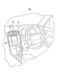
- FIG. 1 shows an example of a usage environment of a passage detection system 100 according to an embodiment.
- the passage detection system 100 is a system that detects when a vehicle passes a charging point.
- the billing point is a position where billing processing should be performed in road pricing.
- the billing point may be an example of a “predetermined position” in the present invention.
- the passage detection system 100 includes an on-vehicle device 110, a GPS receiver 130, and a display 150.
- the vehicle-mounted device 110 may be an example of the “passage detection device” in the present invention.
- the GPS receiver 130 may be an example of the “positioning device” in the present invention.
- the GPS receiver 130 is a device for positioning its own position by using both radio navigation and autonomous navigation. More specifically, the GPS receiver 130 includes a GPS antenna, an accelerometer, and an angular velocity meter.
- the GPS antenna is an antenna that receives radio waves from GPS satellites.
- the accelerometer is a measuring instrument that measures a change in acceleration when the vehicle moves.
- the angular velocity meter is a measuring instrument that measures a change in angular velocity when the vehicle moves.
- the GPS receiver 130 is provided at a position where the GPS antenna is not shielded, such as on the dashboard D of the vehicle.
- the GPS receiver 130 is electrically connected to the vehicle-mounted device 110.
- the GPS receiver 130 measures its own position by using both GPS radio navigation and autonomous navigation using an accelerometer and an angular velocity meter.
- the GPS receiver 130 outputs data indicating the positioning result to the vehicle-mounted device 110.
- the vehicle-mounted device 110 is a device that detects when a vehicle passes a charging point. More specifically, the vehicle-mounted device 110 is provided at a position that can be reached by the driver without disturbing driving, such as the side surface of the center console C of the vehicle.
- the vehicle-mounted device 110 is electrically connected to the GPS receiver 130 and the display 150.
- An IC (Integrated Circuit) card is inserted into the card slot I of the vehicle-mounted device 110.
- application data and the like for realizing a security function are mounted in addition to a nonvolatile memory for storing user information of the passage detection system 100, billing information including a usage history, and the like. Is done.
- the vehicle-mounted device 110 When the vehicle-mounted device 110 receives input of data output from the GPS receiver 130, the vehicle-mounted device 110 determines whether or not the vehicle has passed the charge point. If the vehicle-mounted device 110 determines that the vehicle has passed the charging point, it performs charging processing. The in-vehicle device 110 outputs data indicating the result of the charging process to the display 150.
- the display 150 is a device that displays characters and figures. More specifically, the display 150 is provided at a position where the driver can visually recognize, such as the center console C of the vehicle.
- the display 150 is electrically connected to the vehicle-mounted device 110. When the display 150 receives input of data output from the vehicle-mounted device 110, the display 150 displays the result of the accounting process indicated by the data.
- the passage detection system 100 includes one GPS receiver 130 and a display 150
- the passage detection system 100 may include a plurality of GPS receivers 130 and a display 150.
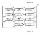
- FIG. 2 shows an example of a block configuration of the vehicle-mounted device 110.
- the vehicle-mounted device 110 includes a positioning result data input receiving unit 111, a position specifying unit 112, a map matching unit 113, a traveling state specifying unit 114, a chance error calculating unit 115, a passage determining unit 116, a charging processing unit 117, a data output unit 118, A map data storage unit 119, a systematic error information storage unit 120, and a charging point information storage unit 121 are included.
- a positioning result data input receiving unit 111 includes a positioning result data input receiving unit 111, a position specifying unit 112, a map matching unit 113, a traveling state specifying unit 114, a chance error calculating unit 115, a passage determining unit 116, a charging processing unit 117, a data output unit 118, A map data storage unit 119, a systematic error information storage unit 120, and a charging point information storage unit 121 are included.
- the function and operation of each component
- the positioning result data input receiving unit 111 receives input of data indicating the positioning result output from the GPS receiver 130.
- the position specifying unit 112 corrects the positioning result by the GPS receiver 130 based on the system error information prepared in advance related to the system error of the positioning result by the GPS receiver 130 and the traveling state of the vehicle, and thereby determines the position of the vehicle. Is identified. More specifically, the position specifying unit 112 is based on the system error information prepared in advance regarding the system error of the positioning result by the GPS receiver 130 and the running state of the vehicle specified by the running state specifying unit 114. The position of the vehicle is specified by correcting the positioning result by the GPS receiver 130.
- the traveling state of the vehicle roughly indicates either whether the vehicle is traveling or stopped.
- the traveling state of a traveling vehicle refers to any of straight traveling, traveling while turning right, or traveling while turning left.
- the systematic error is measured by systematically shifting the position coordinate of the positioning result by the GPS receiver 130 with respect to the true position coordinate of the position as long as positioning is performed at the same position in the same traveling state. It shall indicate an error.
- the true position coordinates are position coordinates on a map, for example.
- the map matching unit 113 performs map matching on the position specified by the position specifying unit 112.
- the map matching is a process for forcibly matching the position specified by the position specifying unit 112 outside the road on the map on the assumption that the vehicle runs on the road. .
- the traveling state identifying unit 114 identifies the traveling state of the vehicle based on the temporal change of the position identified by the position identifying unit 112 so far.
- the accidental error calculation unit 115 performs positioning by the GPS receiver 130 based on the amount of deviation between the first position specified by the position specifying unit 112 and the second position indicated by the map matching result obtained by the map matching unit 113. Calculate the accidental error of the result.
- the accidental error refers to an error that varies for each positioning even if positioning is performed at the same position in the same traveling state.
- the passage determination unit 116 determines whether or not the vehicle has passed the charging point based on the change over time of the position specified by the position specifying unit 112. More specifically, the passage determination unit 116 determines that the vehicle has not passed the charging point when the charging point is within the range of the accidental error calculated by the accidental error calculation unit 115.
- the billing processing unit 117 performs billing processing when the vehicle passes the billing point.
- the data output unit 118 outputs data indicating the result of the billing process to the display 150.
- the map data storage unit 119 stores digital map data.
- the digital map is a map that can be computerized and digitized.
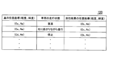
- FIG. 3 shows an example of information stored in the systematic error information storage unit 120 in a table format.
- the systematic error information storage unit 120 information on true position coordinates (longitude, latitude), a running state of the vehicle, and position coordinates (longitude, latitude) of the positioning result are stored in association with each other. Further, the information stored in the systematic error information storage unit 120 may be an example of “systematic error information” in the present invention.
- the information of “true position coordinates (longitude, latitude)” is information indicating the longitude and latitude on the digital map. More specifically, the information of “true position coordinates (longitude, latitude)” indicates the longitude and latitude on the digital map of the position where a systematic error occurs in the positioning result of the GPS receiver 130 around the charging point. .
- the “vehicle running state” information is information indicating the running state of the vehicle at the position indicated by the “true position coordinates (longitude, latitude)” information.
- the information on the “position coordinates (longitude, latitude) of the positioning result” indicates that the driving state of the vehicle is indicated by the information of “vehicle driving state” at the position indicated by the information of “true position coordinates (longitude, latitude)”. It is the information which shows the positioning result of the GPS receiver 130 in the case of being in a state.
- the amount of deviation between the position coordinates indicated by the information of “true position coordinates (longitude, latitude)” and the position coordinates indicated by the information of “position coordinates (longitude, latitude) of the positioning result” Is a systematic error when the traveling state of the vehicle is the state represented by the information “traveling state of the vehicle” at the position indicated by the information “true position coordinates (longitude, latitude)”.
- the true position coordinate where the vehicle exists indicates “(Ea, Na)”. Even if the position coordinate of the positioning result by the GPS receiver 130 is “(Eb, Nb)”, if the running state of the vehicle at that time is “stop”, the true position where the vehicle exists The coordinates indicate “(Ed, Nd)”. In addition, even if the true position coordinate is “(Ea, Na)”, if the traveling state of the vehicle at that position is “traveling while turning right”, the positioning result by the GPS receiver 130 is “(Ec , Nc) ”.
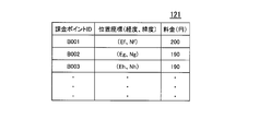
- FIG. 4 shows an example of information stored in the charging point information storage unit 121 in a table format.
- the charging point information storage unit 121 stores charging point ID (identifier), position coordinates (longitude, latitude), and fee (yen) in association with each other.
- charging point ID is an identification code for uniquely identifying each charging point among a plurality of charging points.
- the information of “position coordinates (longitude, latitude)” is information indicating the longitude and latitude on the digital map of the charging point indicated by the information of “charging point ID”.
- the “charge (yen)” information is information indicating the amount of charge to be charged when passing the charging point indicated by the information of “charging point ID”.
- a charging point having a position coordinate of “(Ef, Nf)” is a charging point for which “200 (yen)” is charged.
- FIG. 5 shows an example of the operation flow of the vehicle-mounted device 110.
- this operation flow a process for map matching the position of the vehicle will be described in detail.
- both FIGS. 1 to 4 are referred to.
- the GPS receiver 130 uses GPS radio navigation and autonomous navigation using an accelerometer and an angular velocity meter in combination to measure its own position at predetermined intervals.
- the GPS receiver 130 sequentially outputs data indicating the positioning result to the vehicle-mounted device 110.
- the positioning result data input receiving unit 111 of the in-vehicle device 110 receives the input of the data indicating the positioning result output from the GPS receiver 130 (S101), the positioning result data input receiving unit 111 sends the data to the position specifying unit 112.
- the position specifying unit 112 of the vehicle-mounted device 110 receives the data sent from the positioning result data input receiving unit 111
- the position specifying unit 112 uses the information stored in the systematic error information storage unit 120 and the data received from the traveling state specifying unit 114. Based on the traveling state of the vehicle shown, the positioning result indicated by the data received from the positioning result data input receiving unit 111 is corrected to identify the position of the vehicle (S102).
- the position coordinate indicated by the data received from the positioning result data input receiving unit 111 is “(Ea, Na)”
- the vehicle driving state indicated by the latest data received from the driving state specifying unit 114 is “
- the position specifying unit 112 has information “position coordinates (longitude, latitude)” of “(Ea, Na)” among the information stored in the systematic error information storage unit 120,
- the information “(Eb, Nb)” of “true position coordinates (longitude, latitude)” stored in association with the information “traveling state of the vehicle” in correspondence with “straight ahead” is read.
- the position specifying unit 112 specifies the position coordinates (Ea, Na) as the corrected vehicle position.
- the same position coordinates as the positioning results indicated by the data sent from the positioning result data input receiving unit 111 are stored as information of “positional coordinates (longitude, latitude) of positioning results” in the systematic error information storage unit 120. If not, the position specifying unit 112 specifies the position coordinates of the positioning result indicated by the data received from the positioning result data input receiving unit 111 as the position of the vehicle. This is because when no corresponding information is stored in the systematic error information storage unit 120, it means that no systematic error has occurred at that position.
- the position specifying unit 112 sends data indicating the position coordinates of the vehicle specified in this way to the map matching unit 113, the traveling state specifying unit 114, and the accidental error calculating unit 115.
- the map matching unit 113 of the vehicle-mounted device 110 receives the data sent from the position specifying unit 112, the map matching is performed on the position coordinates indicated by the data (S103).
- the map matching unit 113 uses the road shape on the map, the running pattern history of the vehicle, and the like as data, and maps the position coordinates indicated by the data sent from the position specifying unit 112 using a heuristic algorithm. Match.
- the map matching unit 113 sends data indicating the position coordinates after map matching to the traveling state specifying unit 114, the accidental error calculating unit 115, and the passage determining unit 116.
- the traveling state specifying unit 114 of the vehicle-mounted device 110 receives the data sent from the position specifying unit 112 and the map matching unit 113, respectively, the traveling state of the vehicle is determined based on the temporal change of the position coordinates indicated by these data.
- a state is specified (S104).
- the traveling state identification unit 114 identifies whether the vehicle is traveling or stopped based on the temporal change of the position coordinates indicated by the data received from the position identification unit 112. For example, when the amount of change over time of the position coordinates indicated by the plurality of data received from the position specifying unit 112 within a predetermined time is less than a predetermined value, the traveling state specifying unit 114 specifies that the vehicle is stopped. To do. In addition, when the amount of change over time of the position coordinates indicated by the plurality of data received from the position specifying unit 112 within a predetermined time is equal to or greater than a predetermined value, the running state specifying unit 114 specifies that the vehicle is running. To do.
- the traveling state identifying unit 114 determines whether the vehicle is traveling straight or turning right based on the temporal change in the position coordinates indicated by the data received from the map matching unit 113. Determine if it is progressing or turning left. For example, when a change with time in position coordinates indicated by a plurality of data received from the map matching unit 113 within a predetermined time is linear, the traveling state specifying unit 114 specifies that the vehicle is traveling straight. In addition, when the temporal change of the position coordinates indicated by the plurality of data received from the map matching unit 113 within a predetermined time has changed to the northeast or southwest, the traveling state specifying unit 114 turns the vehicle to the right. While progressing, identify. In addition, when the time-dependent change in the position coordinates indicated by the plurality of data received from the map matching unit 113 within a predetermined time has changed to northwest or southeast, the driving state specifying unit 114 turns the vehicle to the left. While progressing, identify.
- the traveling state identification unit 114 sends data indicating the identified traveling state of the vehicle to the position identification unit 112.
- the position specifying unit 112 When the position specifying unit 112 receives the data sent from the positioning result data input receiving unit 111, the position specifying unit 112 receives the data stored in the systematic error information storage unit 120 and the data indicated by the data received from the traveling state specifying unit 114. Based on the running state, the positioning result indicated by the data received from the positioning result data input receiving unit 111 is corrected to identify the position of the vehicle (S102).
- the vehicle-mounted device 110 repeats the processing of steps S101 to S104 each time it receives input of data output from the GPS receiver 130, and map-matches the position of the vehicle.
- FIG. 6 shows an example of the operation flow of the vehicle-mounted device 110.
- the process for calculating the range of the chance error at the current position of the vehicle will be described in detail.
- FIGS. 1 to 5 and FIG. 7 are referred to.
- FIG. 7 shows an example of a method for calculating the range of chance errors. Further, among the steps of the operation flow shown in FIG. 6, steps having the same reference numerals as those in the operation flow shown in FIG. 5 indicate similar operations.
- the position specifying unit 112 Each time the position specifying unit 112 specifies the position coordinates of the vehicle, the position specifying unit 112 sends data indicating the position coordinates to the chance error calculating unit 115. Further, each time map matching is performed, the map matching unit 113 sends data indicating the position coordinates after map matching to the accidental error calculation unit 115.
- the accidental error calculation unit 115 of the vehicle-mounted device 110 receives the data sent from the position specifying unit 112 and the map matching unit 113, respectively, and the position coordinates indicated by the data received from the position specifying unit 112 and the map matching unit 113. Based on the amount of deviation from the position coordinates indicated by the data received from, the range of the accidental error of the positioning result by the GPS receiver 130 is sequentially calculated (S105).
- the position coordinates indicated by the data received from the position specifying unit 112 may be an example of the “first position” in the present invention.
- the position coordinates indicated by the data received from the map matching unit 113 may be an example of the “second position” in the present invention.
- Deviation amounts E1 to En between the position coordinates of the respective positions P1 to Pn specified by the position specifying unit 112 and the position coordinates of the respective positions M1 to Mn as a result of map matching of the respective positions P1 to Pn by the map matching unit 113 The root mean square Err is calculated (formula (1)).
- the chance error calculation unit 115 multiplies the value of the root mean square Err by N (N is a positive number) to calculate the range of the chance error.
- N is a positive number
- the range of the chance error becomes wider as the value of N is larger.
- the coincidence error calculation unit 115 sends data indicating the range of the calculated coincidence error to the passage determination unit 116.
- the vehicle-mounted device 110 can perform processing with reference to the range of the chance error at the current position of the vehicle.
- FIG. 8 shows an example of the operation flow of the vehicle-mounted device 110.
- this operation flow a process for detecting when a vehicle passes a charging point will be described in detail.
- both FIGS. 1 to 7 are referred to.
- steps denoted by the same reference numerals as those in the operation flow shown in FIGS. 5 and 6 indicate the same operation.
- the map matching unit 113 sends data indicating the position coordinates after map matching to the passage determining unit 116 each time map matching is performed. In addition, every time the accidental error calculation unit 115 calculates the range of accidental miscalculation, the accidental error calculation unit 115 sends data indicating the range of the accidental error to the passage determination unit 116.
- the passage determination unit 116 of the in-vehicle device 110 receives the data sent from the map matching unit 113 and the accidental error calculation unit 115, whether the vehicle has passed the charge point based on the information indicated by these data. It is sequentially determined whether or not (S106). For example, the passage determination unit 116 uses the position coordinates after map matching indicated by the data received from the map matching unit 113 and the information of “position coordinates (longitude, latitude)” stored in the charging point information storage unit 121. Compare the position coordinates shown.
- the passage determination unit 116 determines that the “position coordinates (longitude, The pass determination is started for the billing point at the position coordinate indicated by the “latitude” information. For example, the pass determination is performed while the position coordinates of the billing point to be passed are within the range of the chance error indicated by the data received from the chance error calculation unit 115 centered on the position coordinates after the map matching. The unit 116 determines that the vehicle has not passed the charging point (S106: No).
- the passage determination unit 116 determines that the vehicle has passed the charging point (S106). : Yes).
- the passing determining unit 116 transmits data indicating information on the “charging point ID” of the charging point to the charging processing unit 117.
- the billing processing unit 117 of the in-vehicle device 110 Upon receiving the data sent from the passage determination unit 116, the billing processing unit 117 of the in-vehicle device 110 receives the data from the passage determination unit 116 among the “charge (yen)” information stored in the billing point information storage unit 121. The “charge (yen)” information stored in association with the “charge point ID” information indicated by the received data is read. The billing processing unit 117 charges the toll by removing the electronic money equivalent to the fee indicated by the information from the IC card inserted in the card slot I of the vehicle-mounted device 110 (S107). The billing processing unit 117 sends data indicating the result of the billing processing to the data output unit 118.
- the data output unit 118 of the vehicle-mounted device 110 When the data output unit 118 of the vehicle-mounted device 110 receives the data sent from the billing processing unit 117, the data output unit 118 outputs data for displaying the result of the billing process indicated by the data to the display 150 (S108).
- the result of the billing process is displayed on the display 150.
- the passage detection system 100 may include a speaker instead of the display 150 or together with the display 150.
- the data output unit 118 of the vehicle-mounted device outputs data for outputting the result of the charging process as a sound to the speaker.
- the passage detection system 100 includes the GPS receiver 130 that measures its own position by using both radio navigation and autonomous navigation. Moreover, the passage detection system 100 includes an in-vehicle device 110 that detects when a vehicle passes a charging point. The vehicle-mounted device 110 specifies the position of the vehicle by correcting the positioning result by the positioning device based on the system error information prepared in advance regarding the system error of the positioning result by the GPS receiver 130 and the traveling state of the vehicle. . The in-vehicle device 110 determines whether or not the vehicle has passed the charging point based on the change over time of the specified position.
- the vehicle has passed the charging point without being affected by the system error of the positioning result by the GPS receiver 130. If so, it can be detected.
- the vehicle-mounted device 110 identifies the running state of the vehicle based on the temporal change in the vehicle position identified up to now.
- the in-vehicle device 110 corrects the positioning result by the GPS receiver 130 based on the system error information prepared in advance regarding the system error of the positioning result by the GPS receiver 130 and the identified running state of the vehicle. Identify the location.
- the driving state of the vehicle can be specified each time the position of the vehicle is specified.
- the vehicle-mounted device 110 performs map matching on the position of the specified vehicle.
- the in-vehicle device 110 calculates a coincidence error of the positioning result by the GPS receiver 130 based on the amount of deviation between the specified vehicle position and the position indicated by the map matching result.
- the vehicle-mounted device 110 determines that the vehicle has not passed the charging point when the charging point is within the range of the calculated accidental error.
- the vehicle-mounted device 110 uses the GPS receiver 130 based on the system error information prepared in advance regarding the system error of the positioning result obtained by the GPS receiver 130 and the traveling state of the vehicle. Based on the amount of deviation between the first position of the vehicle specified by correcting the first position and the second position indicated by the result of map matching the first position, the accidental error of the positioning result by the GPS receiver 130 is calculated. The example to calculate was demonstrated. However, the vehicle-mounted device 110 can calculate the accidental error of the positioning result by the GPS receiver 130 by another method. For example, the in-vehicle device 110 receives the GPS signal based on the amount of deviation between the first position of the positioning result by the GPS receiver 130 and the second position indicated by the map matching result of the positioning result by the GPS receiver 130. The accidental error of the positioning result by the machine 130 may be calculated.
- FIG. 9 shows an example of a hardware configuration of a computer 800 that constitutes the vehicle-mounted device 110 according to the present embodiment.
- a computer 800 includes a CPU (Central Processing Unit) 802, a RAM (Random Access Memory) 803, a graphic controller 804, and a display 805 that are mutually connected by a host controller 801, and input / output An input / output unit having a communication interface 807, a hard disk drive 808, and a CD-ROM (Compact Disk Only Memory) drive 809 connected to each other by the controller 806, and a ROM (Read Only Memory) connected to the input / output controller 806 810, legacy input / output having flexible disk drive 811 and input / output chip 812 Provided with a door.
- a CPU Central Processing Unit
- RAM Random Access Memory
- FIG. 9 shows an example of a hardware configuration of a computer 800 that constitutes the vehicle-mounted device 110 according to the present embodiment.
- a computer 800 includes a CPU (Central Processing Unit) 802, a RAM (Ran
- the host controller 801 connects the RAM 803, the CPU 802 that accesses the RAM 803 at a high transfer rate, and the graphic controller 804.
- the CPU 802 operates based on programs stored in the ROM 810 and the RAM 803 and controls each unit.
- the graphic controller 804 acquires image data generated on a frame buffer provided in the RAM 803 by the CPU 802 and the like and displays the image data on the display 805.
- the graphic controller 804 may include a frame buffer for storing image data generated by the CPU 802 or the like.
- the input / output controller 806 connects the host controller 801 to the communication interface 807, the hard disk drive 808, and the CD-ROM drive 809, which are relatively high-speed input / output devices.
- the hard disk drive 808 stores programs and data used by the CPU 802 in the computer 800.
- the CD-ROM drive 809 reads a program or data from the CD-ROM 892 and provides it to the hard disk drive 808 via the RAM 803.
- the input / output controller 806 is connected to the ROM 810, the flexible disk drive 811 and the input / output chip 812, which are relatively low-speed input / output devices.
- the ROM 810 stores a boot program that is executed when the computer 800 is started and / or a program that depends on the hardware of the computer 800.
- the flexible disk drive 811 reads a program or data from the flexible disk 893 and provides it to the hard disk drive 808 via the RAM 803.
- the input / output chip 812 connects the flexible disk drive 811 to the input / output controller 806 and connects various input / output devices to the input / output controller 806 via, for example, a parallel port, serial port, keyboard port, mouse port, and the like. To do.
- the program provided to the hard disk drive 808 via the RAM 803 is stored in a recording medium such as a flexible disk 893, a CD-ROM 892, or an IC (Integrated Circuit) card and provided by the user.
- the program is read from the recording medium, installed in the hard disk drive 808 in the computer 800 via the RAM 803, and executed by the CPU 802.
- a program that is installed in the computer 800 and causes the computer 800 to function as the vehicle-mounted device 110 causes the computer 800 to have system error information prepared in advance relating to the system error of the positioning result by the GPS receiver 130 in step S102, and the running state of the vehicle.
- the position specifying unit 112 that corrects the positioning result by the GPS receiver 130 to specify the position of the vehicle and the time-dependent change of the position specified by the position specifying unit 112 are Is made to function as a passage determination unit 116 that determines whether or not a billing point has passed.
- the program causes the computer 800 to check the running state identifying unit 114 that identifies the traveling state of the vehicle in step S104 based on the change over time of the position identified by the position identifying unit 112 so far, and the GPS receiver.
- the positioning result by the GPS receiver 130 is corrected based on the system error information prepared in advance relating to the systematic error of the positioning result 130 and the traveling state of the vehicle identified by the traveling state identifying unit 114. You may make it function as the position specific
- the program includes a map matching unit 113 that performs map matching in step S103 on the position specified by the position specifying unit 112, a position specified by the position specifying unit 112, and a map matching unit 113 that performs map matching.
- the random error calculation unit 115 that calculates the random error of the positioning result by the GPS receiver 130, and the range of the random error calculated by the random error calculation unit 115 If there is a charging point, the pass determination unit 116 may determine that the vehicle has not passed the charging point in step S106.
- the information processing described in these programs is read into the computer 800, whereby the positioning result data input receiving unit 111 and the position specifying unit 112, which are specific means in which the software and the various hardware resources described above cooperate. , Map matching unit 113, driving state specifying unit 114, chance error calculating unit 115, passage determining unit 116, charging processing unit 117, data output unit 118, map data storage unit 119, systematic error information storage unit 120, and charging point information It functions as the storage unit 121.
- Map matching unit 113 Map matching unit 113, driving state specifying unit 114, chance error calculating unit 115, passage determining unit 116, charging processing unit 117, data output unit 118, map data storage unit 119, systematic error information storage unit 120, and charging point information It functions as the storage unit 121.
- the CPU 802 executes a communication program loaded on the RAM 803 and executes a communication interface based on the processing content described in the communication program.
- a communication process is instructed to 807.
- the communication interface 807 reads transmission data stored in a transmission buffer area or the like provided on a storage device such as the RAM 803, the hard disk drive 808, the flexible disk 893, or the CD-ROM 892, and sends it to the network.
- the reception data transmitted or received from the network is written into a reception buffer area or the like provided on the storage device.
- the communication interface 807 may transfer transmission / reception data to / from the storage device by the direct memory access method. Instead, the CPU 802 reads data from the transfer source storage device or the communication interface 807.
- the transmission / reception data may be transferred by writing the data to the transfer destination communication interface 807 or the storage device.
- the CPU 802 transfers all or a necessary portion of the files or database stored in the external storage device such as the hard disk drive 808, CD-ROM 892, and flexible disk 893 to the RAM 803 by direct memory access transfer or the like.
- the data is read and various processes are performed on the data on the RAM 803.
- the CPU 802 writes the processed data back to the external storage device by direct memory access transfer or the like.
- the RAM 803 can be regarded as temporarily holding the contents of the external storage device, in the present embodiment, the RAM 803 and the external storage device are collectively referred to as a memory, a storage unit, a storage device, or the like.
- Various types of information such as various programs, data, tables, and databases in the present embodiment are stored on such a storage device and are subjected to information processing.
- the CPU 802 can hold a part of the RAM 803 in the cache memory and perform reading and writing on the cache memory.
- the cache memory bears a part of the function of the RAM 803, the cache memory is also included in the RAM 803, the memory, and / or the storage device unless otherwise indicated.
- the CPU 802 performs various operations, such as various operations, information processing, condition determination, information retrieval, replacement, and the like described in the present embodiment for data read from the RAM 803 and specified by a command sequence of the program. Is written back to the RAM 803. For example, when performing the condition determination, the CPU 802 satisfies the conditions such that the various variables shown in the present embodiment are larger, smaller, above, below, or equal to other variables or constants. If the condition is satisfied or not satisfied, the program branches to a different instruction sequence or calls a subroutine.
- the CPU 802 can search for information stored in a file in a storage device or a database. For example, when a plurality of entries in which the attribute value of the second attribute is associated with the attribute value of the first attribute are stored in the storage device, the CPU 802 stores the plurality of entries stored in the storage device. An entry that matches the condition in which the attribute value of the first attribute is designated is retrieved, and the attribute value of the second attribute stored in the entry is read. Thereby, the attribute value of the 2nd attribute matched with the 1st attribute which satisfy
- the storage medium is an optical recording medium such as a DVD (Digital Versatile Disk) or CD (Compact Disk), a magneto-optical recording medium such as an MO (Magneto-Optical disk), or a tape medium.
- a semiconductor memory such as an IC card can be used.
- a storage medium such as a hard disk or RAM provided in a server system connected to a dedicated communication network or the Internet may be used as a recording medium, and the program may be provided to the computer 800 via the network.
- passage detection system passage detection method, passage detection device, program, and recording medium, for example, even if the vehicle is traveling on a road where the aerial view cannot be sufficiently secured, When the vehicle passes through a predetermined position without being affected, it can be detected.
Landscapes
- Engineering & Computer Science (AREA)
- Radar, Positioning & Navigation (AREA)
- Remote Sensing (AREA)
- Physics & Mathematics (AREA)
- General Physics & Mathematics (AREA)
- Computer Networks & Wireless Communication (AREA)
- Business, Economics & Management (AREA)
- Finance (AREA)
- Navigation (AREA)
- Instructional Devices (AREA)
- Devices For Checking Fares Or Tickets At Control Points (AREA)
- Position Fixing By Use Of Radio Waves (AREA)
Abstract
この通過検知装置システムは、電波航法と自律航法とを併用して自位置を測位する測位装置(130)と、車両が所定位置を通過した場合に、それを検知する通過検知装置(110)とを備え、通過検知装置(110)は、測位装置(130)による測位結果の系統誤差に関する予め用意された系統誤差情報と、車両の走行状態とに基づいて、測位装置(130)による測位結果を補正して、車両の位置を特定する位置特定部と、位置特定部が特定した位置の経時的変化に基づいて、車両が所定位置を通過したか否かを判定する通過判定部とを有する。
Description
本発明は、通過検知システム、通過検知方法、通過検知装置、プログラム、及び記録媒体に関する。特に本発明は、車両が所定位置を通過した場合に、それを検知する通過検知システム、通過検知方法、通過検知装置、当該通過検知装置としてコンピュータを機能させるプログラム、並びに当該プログラムを記録した記録媒体に関する。本願は、2013年2月22日に、日本に出願された特願2013-033201号に基づき優先権を主張し、その内容をここに援用する。
現在、車両の位置特定は、GPS(Global Positioning System)による方法とジャイロ等を用いた自律航法の両方を併用したシステムによって行われているものが主流である。
GPSは、複数のGPS衛星からの電波を受信することによって、その物体の絶対位置を計測するシステムである。しかしながら、GPS衛星の電波が届かないビル陰やトンネルにおいては、このシステムによって車両の位置特定を行うことはできない。
自律航法は、電波の届かない場所での車両の位置特定を行う目的で用いられる。自律航法においては、先ず初期位置を定めた後、車載の走行距離センサーと方位センサーによって初期位置からの移動距離、方向を計算し、自車位置を求める。走行距離センサーには、タイヤの回転数から走行距離を計測する車速センサーが主に用いられている。方位センサーには、旋回方位と量を検出するジャイロが主に用いられている。
現在は、これら2つの技術を併用することによって数十メートル精度での自車位置特定を実現している。最近は、精度を高める技術も検討されている。例えば、既に実用化されているものとしては、DGPS(Differential GPS)と呼ばれる技術がある。この技術は、予め精確な位置が計測されている基準局におけるGPS衛星からの電波の届き具合を計測することにより電波が地上に到達するまでの誤差を把握し、これを示すディファレンシャル補正電波を近くの利用者に送信することによって10メートル程度の精度を実現する。
このような背景に関連する技術としては、様々なものが知られている(例えば、特許文献1参照。)。
例えば、特許文献1には、車両に搭載され予め設定された課金エリアを車両が走行した際、課金エリアについて定められた課金レートと課金エリア内における走行距離に応じて車両に対して課金を行う装置が記載されている。より具体的に説明すると、この装置は、GPS衛星からの電波に応じて車両の位置を求め車両位置データを得る。この装置は、課金エリアの位置を示す課金エリア情報が与えられ、車両位置データが示す車両の位置と課金エリア情報が示す課金エリアの位置とに応じて車両が課金エリアに近づいたか否かを判定する。車両が課金エリアに近づいたと判定すると、GPS衛星からの電波に応じて得られた基地局の位置と基地局が配置された基準点との誤差に応じた位置補正データを用いて測位を支援する基地局支援測位を起動する。この装置は、位置補正データに応じて車両位置データを補正する。この装置は、車両位置データに応じて車両が課金エリアに位置するか否かを判定して車両が課金エリアに位置する際の走行距離と課金レートとに応じて課金額を決定する。この装置は、安価なコストによって、しかも課金エリアを通過する車両に対して適切な課金を行うことができる。
特許文献1に記載の装置のような、車載型のDGPSを用いた測位方法は、車両の位置を高精度、且つ効率的に測位するための有効な手段である。しかしながら、車両の位置特定は、上空視界が十分に確保できない位置や、ディファレンシャル補正電波の受信が困難な位置等においては、必ずしも保証された精度によって測位可能とは限らない。
車両が有料道路の課金ポイントを通過した場合に課金処理を行うロードプライシングにおいて、課金処理を行う車載器は、車両が有料道路の課金ポイントを通過したか否かを精確に検知する必要がある。
しかしながら、上空視界が十分に確保できない位置等においては、車両の位置を精確に測位することができないため、課金ポイントを通過したにも拘らず課金処理が行われなかったり、課金ポイントを通過していないにも拘らず課金処理が行われたりする可能性がある。
本発明の第1の態様によれば、車両が所定位置を通過した場合に、それを検知する通過検知システムは、電波航法と自律航法とを併用して自位置を測位する測位装置と、車両が所定位置を通過した場合に、それを検知する通過検知装置とを備える。この通過検知装置は、測位装置による測位結果の系統誤差に関する予め用意された系統誤差情報と、車両の走行状態とに基づいて、測位装置による測位結果を補正して、車両の位置を特定する位置特定部と、位置特定部が特定した位置の経時的変化に基づいて、車両が所定位置を通過したか否かを判定する通過判定部とを有する。
通過検知装置は、位置特定部が現在までに特定した位置の経時的変化に基づいて、車両の走行状態を特定する走行状態特定部を更に有してよい。また、位置特定部は、測位装置による測位結果の系統誤差に関する予め用意された系統誤差情報と、走行状態特定部が特定した車両の走行状態とに基づいて、測位装置による測位結果を補正して、車両の位置を特定してよい。
通過検知装置は、位置特定部が特定した位置をマップマッチングするマップマッチング部と、位置特定部が特定した第1の位置と、マップマッチング部がマップマッチングした結果によって示される第2の位置とのずれ量に基づいて、測位装置による測位結果の偶然誤差を算出する偶然誤差算出部とを更に有する。また、通過判定部は、偶然誤差算出部が算出した偶然誤差の範囲内に所定位置が入っている場合、車両が所定位置を通過していないと判定してよい。
本発明の第2の態様によれば、車両が所定位置を通過した場合に、それを検知する通過検知システムは、電波航法と自律航法とを併用して自位置を測位する測位装置と、前記車両が前記所定位置を通過した場合に、それを検知する通過検知装置とを備える。前記通過検知装置は、前記測位装置による測位結果をマップマッチングするマップマッチング部と、前記測位装置による測位結果の第1の位置と、前記マップマッチング部がマップマッチングした結果によって示される第2の位置とのずれ量に基づいて、前記測位装置による測位結果の偶然誤差を算出する偶然誤差算出部と、前記偶然誤差算出部が算出した偶然誤差の範囲内に前記所定位置が入っている場合、前記車両が前記所定位置を通過していないと判定する通過判定部とを有する。
本発明の第3の態様によれば、車両が所定位置を通過した場合に、それを検知する通過検知方法は、電波航法と自律航法とを併用して自位置を測位する測位装置による測位結果の系統誤差に関する予め用意された系統誤差情報と、車両の走行状態とに基づいて、測位装置による測位結果を補正して、車両の位置を特定する位置特定段階と、位置特定段階において特定された位置の経時的変化に基づいて、車両が所定位置を通過したか否かを判定する通過判定段階とを備える。
本発明の第4の態様によれば、車両が所定位置を通過した場合に、それを検知する通過検知方法は、電波航法と自律航法とを併用して自位置を測位する測位装置による測位結果をマップマッチングするマップマッチング段階と、前記測位装置による測位結果の第1の位置と、前記マップマッチング段階においてマップマッチングされた結果によって示される第2の位置とのずれ量に基づいて、前記測位装置による測位結果の偶然誤差を算出する偶然誤差算出段階と、前記偶然誤差算出段階において算出された偶然誤差の範囲内に前記所定位置が入っている場合、前記車両が前記所定位置を通過していないと判定する通過判定段階とを備える。
本発明の第5の態様によれば、車両が所定位置を通過した場合に、それを検知する通過検知装置は、電波航法と自律航法とを併用して自位置を測位する測位装置による測位結果の系統誤差に関する予め用意された系統誤差情報と、車両の走行状態とに基づいて、測位装置による測位結果を補正して、車両の位置を特定する位置特定部と、位置特定部が特定した位置の経時的変化に基づいて、車両が所定位置を通過したか否かを判定する通過判定部とを備える。
本発明の第6の態様によれば、車両が所定位置を通過した場合に、それを検知する通過検知装置として、コンピュータを機能させるプログラムは、前記コンピュータを、電波航法と自律航法とを併用して自位置を測位する測位装置による測位結果をマップマッチングするマップマッチング部、前記測位装置による測位結果の第1の位置と、前記マップマッチング部がマップマッチングした結果によって示される第2の位置とのずれ量に基づいて、前記測位装置による測位結果の偶然誤差を算出する偶然誤差算出部、前記偶然誤差算出部が算出した偶然誤差の範囲内に前記所定位置が入っている場合、前記車両が前記所定位置を通過していないと判定する通過判定部として機能させる。
本発明の第7の態様によれば、車両が所定位置を通過した場合に、それを検知する通過検知装置として、コンピュータを機能させるプログラムは、コンピュータを、電波航法と自律航法とを併用して自位置を測位する測位装置による測位結果の系統誤差に関する予め用意された系統誤差情報と、車両の走行状態とに基づいて、測位装置による測位結果を補正して、車両の位置を特定する位置特定部、位置特定部が特定した位置の経時的変化に基づいて、車両が所定位置を通過したか否かを判定する通過判定部として機能させる。
本発明の第8の態様によれば、車両が所定位置を通過した場合に、それを検知する通過検知装置として、コンピュータを機能させるプログラムは、前記コンピュータを、電波航法と自律航法とを併用して自位置を測位する測位装置による測位結果をマップマッチングするマップマッチング部、前記測位装置による測位結果の第1の位置と、前記マップマッチング部がマップマッチングした結果によって示される第2の位置とのずれ量に基づいて、前記測位装置による測位結果の偶然誤差を算出する偶然誤差算出部、前記偶然誤差算出部が算出した偶然誤差の範囲内に前記所定位置が入っている場合、前記車両が前記所定位置を通過していないと判定する通過判定部として機能させる。
本発明の第9の態様によれば、車両が所定位置を通過した場合に、それを検知する通過検知装置として、コンピュータを機能させるプログラムを記録した記録媒体は、コンピュータを、電波航法と自律航法とを併用して自位置を測位する測位装置による測位結果の系統誤差に関する予め用意された系統誤差情報と、車両の走行状態とに基づいて、測位装置による測位結果を補正して、車両の位置を特定する位置特定部、位置特定部が特定した位置の経時的変化に基づいて、車両が所定位置を通過したか否かを判定する通過判定部として機能させるプログラムが記録されている。
本発明の第10の態様によれば、車両が所定位置を通過した場合に、それを検知する通過検知装置として、コンピュータを機能させるプログラムを記録した記録媒体は、前記コンピュータを、電波航法と自律航法とを併用して自位置を測位する測位装置による測位結果をマップマッチングするマップマッチング部、前記測位装置による測位結果の第1の位置と、前記マップマッチング部がマップマッチングした結果によって示される第2の位置とのずれ量に基づいて、前記測位装置による測位結果の偶然誤差を算出する偶然誤差算出部、前記偶然誤差算出部が算出した偶然誤差の範囲内に前記所定位置が入っている場合、前記車両が前記所定位置を通過していないと判定する通過判定部として機能させるプログラムが記録されている。
また、上記の発明の概要は、本発明の必要な特徴の全てを列挙したものではない。
また、これらの特徴群のサブコンビネーションもまた、発明となり得る。
また、これらの特徴群のサブコンビネーションもまた、発明となり得る。
上述した通過検知システム、通過検知方法、通過検知装置、プログラム、及び記録媒体によれば、例えば、上空視界が十分に確保できないような道路を走行していても、測位装置による測位結果の誤差の影響を受けることなく、車両が所定位置を通過した場合に、それを検知することができる。
以下、実施形態を通じて本発明を説明する。以下の実施形態は特許請求の範囲にかかる発明を限定するものではない。また、実施形態の中で説明されている特徴の組み合わせの全てが発明の解決手段に必須であるとは限らない。
図1は、一実施形態に係る通過検知システム100の利用環境の一例を示す。通過検知システム100は、車両が課金ポイントを通過した場合に、それを検知するシステムである。ここで、課金ポイントとは、ロードプライシングにおいて課金処理を行うべき位置である。また、課金ポイントは、この発明における「所定位置」の一例であってよい。
通過検知システム100は、車載器110、GPS受信機130、及びディスプレイ150を備える。車載器110は、この発明における「通過検知装置」の一例であってよい。また、GPS受信機130は、この発明における「測位装置」の一例であってよい。
GPS受信機130は、電波航法と自律航法とを併用して自位置を測位する装置である。より具体的に説明すると、GPS受信機130は、GPSアンテナ、加速度計、及び角速度計を備える。ここで、GPSアンテナは、GPS衛星からの電波を受信するアンテナである。また、加速度計は、車両が移動する際の加速度変化を計測する計測器である。また、角速度計は、車両が移動する際の角速度変化を計測する計測器である。GPS受信機130は、例えば、車両のダッシュボードDの上等のような、GPSアンテナが遮蔽されない位置に設けられている。GPS受信機130は、車載器110と電気的に接続されている。GPS受信機130は、GPSによる電波航法と、加速度計、及び角速度計を用いた自律航法とを併用して自位置を測位する。GPS受信機130は、その測位結果を示すデータを、車載器110へ出力する。
車載器110は、車両が課金ポイントを通過した場合に、それを検知する装置である。
より具体的に説明すると、車載器110は、例えば、車両のセンターコンソールCの側面等のような、運転の邪魔にならずに、ドライバーの手の届く位置に設けられている。車載器110は、GPS受信機130、及びディスプレイ150と電気的に接続されている。車載器110のカードスロットIには、IC(Integrated Circuit)カードが挿入される。ここで、ICカード内には、通過検知システム100の利用者の情報や、利用履歴をはじめとする課金情報等を格納する不揮発性メモリの他、セキュリティ機能を実現するためのアプリケーションデータ等が実装される。車載器110は、GPS受信機130から出力されたデータの入力を受け付けると、車両が課金ポイントを通過したか否かを判定する。車載器110は、車両が課金ポイントを通過したと判定した場合、課金処理を行う。車載器110は、課金処理の結果を示すデータを、ディスプレイ150へ出力する。
より具体的に説明すると、車載器110は、例えば、車両のセンターコンソールCの側面等のような、運転の邪魔にならずに、ドライバーの手の届く位置に設けられている。車載器110は、GPS受信機130、及びディスプレイ150と電気的に接続されている。車載器110のカードスロットIには、IC(Integrated Circuit)カードが挿入される。ここで、ICカード内には、通過検知システム100の利用者の情報や、利用履歴をはじめとする課金情報等を格納する不揮発性メモリの他、セキュリティ機能を実現するためのアプリケーションデータ等が実装される。車載器110は、GPS受信機130から出力されたデータの入力を受け付けると、車両が課金ポイントを通過したか否かを判定する。車載器110は、車両が課金ポイントを通過したと判定した場合、課金処理を行う。車載器110は、課金処理の結果を示すデータを、ディスプレイ150へ出力する。
ディスプレイ150は、文字や図形を表示する装置である。より具体的に説明すると、ディスプレイ150は、例えば、車両のセンターコンソールC等のような、ドライバーが視認し得る位置に設けられている。ディスプレイ150は、車載器110と電気的に接続されている。ディスプレイ150は、車載器110から出力されたデータの入力を受け付けると、そのデータによって示される課金処理の結果を表示する。
また、本実施形態においては、通過検知システム100が一つのGPS受信機130、及びディスプレイ150を備える構成について説明する。しかしながら、通過検知システム100は、複数のGPS受信機130、及びディスプレイ150を備えてよい。
図2に、車載器110のブロック構成の一例を示す。車載器110は、測位結果データ入力受付部111、位置特定部112、マップマッチング部113、走行状態特定部114、偶然誤差算出部115、通過判定部116、課金処理部117、データ出力部118、地図データ格納部119、系統誤差情報格納部120、及び課金ポイント情報格納部121を有する。以下の説明においては、各構成要素の機能、及び動作を詳述する。
測位結果データ入力受付部111は、GPS受信機130から出力された、測位結果を示すデータの入力を受け付ける。
位置特定部112は、GPS受信機130による測位結果の系統誤差に関する予め用意された系統誤差情報と、車両の走行状態とに基づいて、GPS受信機130による測位結果を補正して、車両の位置を特定する。より具体的に説明すると、位置特定部112は、GPS受信機130による測位結果の系統誤差に関する予め用意された系統誤差情報と、走行状態特定部114が特定した車両の走行状態とに基づいて、GPS受信機130による測位結果を補正して、車両の位置を特定する。ここで、車両の走行状態とは、大別すると、車両が走行しているか、停止しているかのいずれかを指すものとする。走行している車両の走行状態とは、直進しているか、右に曲がりながら進行しているか、左に曲がりながら進行しているかのいずれかを指すものとする。また、系統誤差とは、同じ位置において、同じ走行状態にて測位する限り、その位置の真の位置座標に対して、GPS受信機130による測位結果の位置座標が系統的にずれて測定される誤差を指すものとする。ここで、真の位置座標とは、例えば、地図上の位置座標である。
マップマッチング部113は、位置特定部112が特定した位置をマップマッチングする。ここで、マップマッチングとは、車両は道路を走るものだという前提を以て、位置特定部112が特定した位置が地図上の道路外にある場合、強制的に地図上の道路内に合わせる処理である。
走行状態特定部114は、位置特定部112が現在までに特定した位置の経時的変化に基づいて、車両の走行状態を特定する。
偶然誤差算出部115は、位置特定部112が特定した第1の位置と、マップマッチング部113がマップマッチングした結果によって示される第2の位置とのずれ量に基づいて、GPS受信機130による測位結果の偶然誤差を算出する。ここで、偶然誤差とは、同じ位置において、同じ走行状態にて測位しても、測位毎にばらつく誤差を指すものとする。
通過判定部116は、位置特定部112が特定した位置の経時的変化に基づいて、車両が課金ポイントを通過したか否かを判定する。より具体的に説明すると、通過判定部116は、偶然誤差算出部115が算出した偶然誤差の範囲内に課金ポイントが入っている場合、車両が課金ポイントを通過していないと判定する。
課金処理部117は、車両が課金ポイントを通過した場合に、課金処理を行う。
データ出力部118は、課金処理の結果を示すデータを、ディスプレイ150へ出力する。
地図データ格納部119には、デジタル地図のデータが格納されている。ここで、デジタル地図とは、電子化されコンピュータ処理が可能な地図である。
図3は、系統誤差情報格納部120に格納されている情報の一例をテーブル形式で示す。系統誤差情報格納部120には、真の位置座標(経度、緯度)、車両の走行状態、及び測位結果の位置座標(経度、緯度)の各情報が対応付けられて格納されている。また、系統誤差情報格納部120に格納されている情報は、この発明における「系統誤差情報」の一例であってよい。
「真の位置座標(経度、緯度)」の情報は、デジタル地図上の経緯度を示す情報である。より具体的に説明すると、「真の位置座標(経度、緯度)」の情報は、課金ポイントの周辺において、GPS受信機130の測位結果に系統誤差が生じる位置のデジタル地図上の経緯度を示す。
「車両の走行状態」の情報は、「真の位置座標(経度、緯度)」の情報によって示される位置における車両の走行状態を示す情報である。
「測位結果の位置座標(経度、緯度)」の情報は、「真の位置座標(経度、緯度)」の情報によって示される位置において、車両の走行状態が「車両の走行状態」の情報によって示される状態である場合の、GPS受信機130の測位結果を示す情報である。より具体的に説明すると、「真の位置座標(経度、緯度)」の情報によって示される位置座標と、「測位結果の位置座標(経度、緯度)」の情報によって示される位置座標とのずれ量は、「真の位置座標(経度、緯度)」の情報によって示される位置において、車両の走行状態が「車両の走行状態」の情報によって示される状態である場合の系統誤差となる。
即ち、図3に示す例の場合、例えば、GPS受信機130による測位結果の位置座標が「(Eb、Nb)」であって、そのときの車両の走行状態が「直進」であれば、その車両が存在している真の位置座標は、「(Ea、Na)」であることを示している。また、GPS受信機130による測位結果の位置座標が「(Eb、Nb)」であっても、そのときの車両の走行状態が「停止」であれば、その車両が存在している真の位置座標は、「(Ed、Nd)」であることを示している。また、真の位置座標が「(Ea、Na)」であっても、その位置における車両の走行状態が「右に曲がりながら進行」であれば、GPS受信機130による測位結果は、「(Ec、Nc)」となることを示している。
図4は、課金ポイント情報格納部121に格納されている情報の一例をテーブル形式で示す。課金ポイント情報格納部121には、課金ポイントID(identifier)、位置座標(経度、緯度)、及び料金(円)の各情報が対応付けられて格納されている。
「課金ポイントID」の情報は、複数の課金ポイントの中で、各課金ポイントを一意に識別するための識別符号である。
「位置座標(経度、緯度)」の情報は、「課金ポイントID」の情報によって示される課金ポイントのデジタル地図上の経緯度を示す情報である。
「料金(円)」の情報は、「課金ポイントID」の情報によって示される課金ポイントを通過する際に、課金処理すべき料金の金額を示す情報である。
即ち、図4に示す例の場合、例えば、位置座標が「(Ef、Nf)」の位置にある課金ポイントは、「200(円)」が課金される課金ポイントであることを示している。
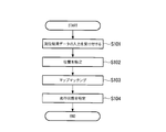
図5は、車載器110の動作フローの一例を示す。この動作フローの説明においては、車両の位置をマップマッチングする処理について詳述する。また、この動作フローの説明においては、図1から図4を共に参照する。
GPS受信機130は、GPSによる電波航法と、加速度計、及び角速度計を用いた自律航法とを併用して自位置を所定時間置きに測位する。GPS受信機130は、その測位結果を示すデータを、車載器110へ順次出力する。
車載器110の測位結果データ入力受付部111は、GPS受信機130から出力された、測位結果を示すデータの入力を受け付けると(S101)、そのデータを、位置特定部112へ送る。
車載器110の位置特定部112は、測位結果データ入力受付部111から送られたデータを受け取ると、系統誤差情報格納部120に格納されている情報と、走行状態特定部114から受け取ったデータによって示される車両の走行状態とに基づいて、測位結果データ入力受付部111から受け取ったデータによって示される測位結果を補正して、車両の位置を特定する(S102)。
例えば、測位結果データ入力受付部111から受け取ったデータによって示される位置座標が「(Ea、Na)」であって、走行状態特定部114から受け取った最新のデータによって示される車両の走行状態が「直進」であれば、位置特定部112は、系統誤差情報格納部120に格納されている情報のうち、「測位結果の位置座標(経度、緯度)」の情報が「(Ea、Na)」、「車両の走行状態」の情報が「直進」に対応付けられて格納されている「真の位置座標(経度、緯度)」の情報「(Eb、Nb)」を読み出す。位置特定部112は、その位置座標(Ea、Na)を、補正後の車両の位置として特定する。
ここで、測位結果データ入力受付部111から送られたデータによって示される測位結果と同じ位置座標が、系統誤差情報格納部120の「測位結果の位置座標(経度、緯度)」の情報として格納されていない場合、位置特定部112は、測位結果データ入力受付部111から受け取ったデータによって示される測位結果の位置座標を、そのまま車両の位置として特定する。これは、系統誤差情報格納部120に該当する情報が格納されていない場合、その位置においては、系統誤差が発生していないことを意味するからである。
位置特定部112は、このようにして特定した車両の位置座標を示すデータを、マップマッチング部113、走行状態特定部114、及び偶然誤差算出部115へ送る。
車載器110のマップマッチング部113は、位置特定部112から送られたデータを受け取ると、そのデータによって示される位置座標をマップマッチングする(S103)。例えば、マップマッチング部113は、地図上の道路形状や、車両の走行パターン履歴等をデータとして用い、ヒューリスティックなアルゴリズムを利用して、位置特定部112から送られたデータによって示される位置座標をマップマッチングする。マップマッチング部113は、マップマッチング後の位置座標を示すデータを、走行状態特定部114、偶然誤差算出部115、及び通過判定部116へ送る。
車載器110の走行状態特定部114は、位置特定部112、及びマップマッチング部113から送られたデータをそれぞれ受け取ると、これらのデータによって示される位置座標の経時的変化に基づいて、車両の走行状態を特定する(S104)。
先ず、走行状態特定部114は、位置特定部112から受け取ったデータによって示される位置座標の経時的変化に基づいて、車両が走行しているか、停止しているかを特定する。例えば、所定時間内に位置特定部112から受け取った複数のデータによって示される位置座標の経時的な変化量が所定値未満である場合、走行状態特定部114は、車両が停止していると特定する。また、所定時間内に位置特定部112から受け取った複数のデータによって示される位置座標の経時的な変化量が所定値以上である場合、走行状態特定部114は、車両が走行していると特定する。
車両が走行していると特定した場合、走行状態特定部114は、マップマッチング部113から受け取ったデータによって示される位置座標の経時的変化に基づいて、車両が直進しているか、右に曲がりながら進行しているか、左に曲がりながら進行しているかを特定する。例えば、所定時間内にマップマッチング部113から受け取った複数のデータによって示される位置座標の経時的な変化が直線的である場合、走行状態特定部114は、車両が直進していると特定する。また、所定時間内にマップマッチング部113から受け取った複数のデータによって示される位置座標の経時的な変化が北東、又は南西に変化している場合、走行状態特定部114は、車両が右に曲がりながら進行していると特定する。また、所定時間内にマップマッチング部113から受け取った複数のデータによって示される位置座標の経時的な変化が北西、又は南東に変化している場合、走行状態特定部114は、車両が左に曲がりながら進行していると特定する。
走行状態特定部114は、特定した車両の走行状態を示すデータを、位置特定部112へ送る。
位置特定部112は、測位結果データ入力受付部111から送られたデータを受け取ると、系統誤差情報格納部120に格納されている情報と、走行状態特定部114から受け取ったデータによって示される車両の走行状態とに基づいて、測位結果データ入力受付部111から受け取ったデータによって示される測位結果を補正して、車両の位置を特定する(S102)。
車載器110は、GPS受信機130から出力されたデータの入力を受け付ける度に、ステップS101~S104の処理を繰り返して、車両の位置をマップマッチングする。
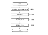
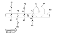
図6は、車載器110の動作フローの一例を示す。この動作フローの説明においては、車両の現在位置における偶然誤差の範囲を算出する処理について詳述する。また、この動作フローの説明においては、図1から図5、図7を共に参照する。図7は、偶然誤差の範囲の算出方法の一例を示す。また、図6に示す動作フローのステップのうち、図5に示す動作フローと同じ符号を付しているステップは、同様の動作を示す。
位置特定部112は、車両の位置座標を特定する度に、その位置座標を示すデータを、偶然誤差算出部115へ送る。また、マップマッチング部113は、マップマッチングを行う度に、マップマッチング後の位置座標を示すデータを、偶然誤差算出部115へ送る。
車載器110の偶然誤差算出部115は、位置特定部112、及びマップマッチング部113から送られたデータをそれぞれ受け取ると、位置特定部112から受け取ったデータによって示される位置座標と、マップマッチング部113から受け取ったデータによって示される位置座標とのずれ量に基づいて、GPS受信機130による測位結果の偶然誤差の範囲を逐次算出する(S105)。ここで、位置特定部112から受け取ったデータによって示される位置座標は、この発明における「第1の位置」の一例であってよい。また、マップマッチング部113から受け取ったデータによって示される位置座標は、この発明における「第2の位置」の一例であってよい。
例えば、偶然誤差算出部115は、図7に示すように、位置特定部112が特定した位置P71における偶然誤差の範囲Ecを算出する場合、その位置P71に車両が至るまでの所定時間内に、位置特定部112が特定した各位置P1~Pnの位置座標と、その各位置P1~Pnをマップマッチング部113がマップマッチングした結果の各位置M1~Mnの位置座標とのずれ量E1~Enについて、二乗平均平方根Errを算出する(式(1))。

偶然誤差算出部115は、その二乗平均平方根Errの値をN(Nは正数)倍して、偶然誤差の範囲を算出する。偶然誤差の範囲は、Nの値が大きいほど広くなる。偶然誤差算出部115は、算出した偶然誤差の範囲を示すデータを、通過判定部116へ送る。
車載器110は、車両の現在位置における偶然誤差の範囲を参照して処理を行うことができる。
図8は、車載器110の動作フローの一例を示す。この動作フローの説明においては、車両が課金ポイントを通過した場合に、それを検知する処理について詳述する。また、この動作フローの説明においては、図1から図7を共に参照する。また、図8に示す動作フローのうち、図5、図6に示す動作フローと同じ符号を付しているステップは、同様の動作を示す。
マップマッチング部113は、マップマッチングを行う度に、マップマッチング後の位置座標を示すデータを、通過判定部116へ送る。また、偶然誤差算出部115は、偶然誤算の範囲を算出する度に、その偶然誤差の範囲を示すデータを、通過判定部116へ送る。
車載器110の通過判定部116は、マップマッチング部113、及び偶然誤差算出部115から送られたデータをそれぞれ受け取ると、これらのデータによって示される情報に基づいて、車両が課金ポイントを通過したか否かを逐次判定する(S106)。例えば、通過判定部116は、マップマッチング部113から受け取ったデータによって示されるマップマッチング後の位置座標と、課金ポイント情報格納部121に格納されている「位置座標(経度、緯度)」の情報によって示される位置座標とを比較する。マップマッチング後の位置座標が、いずれかの「位置座標(経度、緯度)」の情報によって示される位置座標のしきい値内に入った場合、通過判定部116は、その「位置座標(経度、緯度)」の情報によって示される位置座標にある課金ポイントを対象にして通過判定を開始する。例えば、マップマッチング後の位置座標を中心とする、偶然誤差算出部115から受け取ったデータによって示される偶然誤差の範囲内に、通過判定の対象の課金ポイントの位置座標が入っている間、通過判定部116は、車両がその課金ポイントを通過していないと判定する(S106:No)。マップマッチング後の位置座標を中心とする偶然誤差の範囲から、通過判定の対象の課金ポイントの位置座標が外れた場合、通過判定部116は、車両がその課金ポイントを通過したと判定する(S106:Yes)。通過判定部116は、車両が課金ポイントを通過したと判定すると、その課金ポイントの「課金ポイントID」の情報を示すデータを、課金処理部117へ送る。
車載器110の課金処理部117は、通過判定部116から送られたデータを受け取ると、課金ポイント情報格納部121に格納されている「料金(円)」の情報のうち、通過判定部116から受け取ったデータによって示される「課金ポイントID」の情報に対応付けられて格納されている「料金(円)」の情報を読み出す。課金処理部117は、その情報によって示される料金と同額の電子マネーを、車載器110のカードスロットIに挿入されているICカードから引き去り処理することによって、通行料金を課金する(S107)。課金処理部117は、その課金処理の結果を示すデータを、データ出力部118へ送る。
車載器110のデータ出力部118は、課金処理部117から送られたデータを受け取ると、そのデータによって示される課金処理の結果を表示させるためのデータを、ディスプレイ150へ出力する(S108)。
ディスプレイ150には、課金処理の結果が表示される。
また、通過検知システム100は、ディスプレイ150の代わりに、又はディスプレイ150と共に、スピーカを備えてもよい。その場合、車載器のデータ出力部118は、課金処理の結果を音声出力させるためのデータを、スピーカへ出力する。
以上、通過検知システム100は、電波航法と自律航法とを併用して自位置を測位するGPS受信機130を備える。また、通過検知システム100は、車両が課金ポイントを通過した場合に、それを検知する車載器110を備える。車載器110は、GPS受信機130による測位結果の系統誤差に関する予め用意された系統誤差情報と、車両の走行状態とに基づいて、測位装置による測位結果を補正して、車両の位置を特定する。車載器110は、特定した位置の経時的変化に基づいて、車両が課金ポイントを通過したか否かを判定する。
通過検知システム100によっては、例えば、上空視界が十分に確保できないような道路を走行していても、GPS受信機130による測位結果の系統誤差の影響を受けることなく、車両が課金ポイントを通過した場合に、それを検知することができる。
また、車載器110は、現在までに特定した車両の位置の経時的変化に基づいて、車両の走行状態を特定する。車載器110は、GPS受信機130による測位結果の系統誤差に関する予め用意された系統誤差情報と、特定した車両の走行状態とに基づいて、GPS受信機130による測位結果を補正して、車両の位置を特定する。
通過検知システム100によっては、車両の位置を特定する度に、その車両の走行状態を特定することができる。
また、車載器110は、特定した車両の位置をマップマッチングする。車載器110は、特定した車両の位置と、マップマッチングした結果によって示される位置とのずれ量に基づいて、GPS受信機130による測位結果の偶然誤差を算出する。車載器110は、算出した偶然誤差の範囲内に課金ポイントが入っている場合、車両が課金ポイントを通過していないと判定する。
通過検知システム100によっては、偶然誤差の影響を受けて、車両が課金ポイントを通過していないにも拘らず、車両が課金ポイントを通過したとの誤判定をしないことができる。
また、上述した実施形態においては、車載器110が、GPS受信機130による測位結果の系統誤差に関する予め用意された系統誤差情報と、車両の走行状態とに基づいて、GPS受信機130による測位結果を補正して特定した車両の第1の位置と、その第1の位置をマップマッチングした結果によって示される第2の位置とのずれ量に基づいて、GPS受信機130による測位結果の偶然誤差を算出する例について説明した。しかしながら、車載器110は、GPS受信機130による測位結果の偶然誤差を、他の方法によっても算出することができる。例えば、車載器110は、GPS受信機130による測位結果の第1の位置と、GPS受信機130による測位結果をマップマッチングした結果によって示される第2の位置とのずれ量に基づいて、GPS受信機130による測位結果の偶然誤差を算出してもよい。
図9は、本実施形態に係る車載器110を構成するコンピュータ800のハードウェア構成の一例を示す。本実施形態に係るコンピュータ800は、ホストコントローラ801により相互に接続されるCPU(Central Processing Unit)802、RAM(Random Access Memory)803、グラフィックコントローラ804、及びディスプレイ805を有するCPU周辺部と、入出力コントローラ806により相互に接続される通信インターフェース807、ハードディスクドライブ808、及びCD-ROM(Compact Disk Read Only Memory)ドライブ809を有する入出力部と、入出力コントローラ806に接続されるROM(Read Only Memory)810、フレキシブルディスクドライブ811、及び入出力チップ812を有するレガシー入出力部とを備える。
ホストコントローラ801は、RAM803と、高い転送レートでRAM803をアクセスするCPU802、及びグラフィックコントローラ804とを接続する。CPU802は、ROM810、及びRAM803に格納されたプログラムに基づいて動作し、各部の制御を行う。グラフィックコントローラ804は、CPU802等がRAM803内に設けたフレームバッファ上に生成する画像データを取得し、ディスプレイ805上に表示させる。これに代えて、グラフィックコントローラ804は、CPU802等が生成する画像データを格納するフレームバッファを、内部に含んでもよい。
入出力コントローラ806は、ホストコントローラ801と、比較的高速な入出力装置である通信インターフェース807、ハードディスクドライブ808、及びCD-ROMドライブ809を接続する。ハードディスクドライブ808は、コンピュータ800内のCPU802が使用するプログラム、及びデータを格納する。CD-ROMドライブ809は、CD-ROM892からプログラム、又はデータを読み取り、RAM803を介してハードディスクドライブ808に提供する。
また、入出力コントローラ806には、ROM810と、フレキシブルディスクドライブ811、及び入出力チップ812の比較的低速な入出力装置とが接続される。ROM810は、コンピュータ800が起動時に実行するブートプログラム、及び/又はコンピュータ800のハードウェアに依存するプログラム等を格納する。フレキシブルディスクドライブ811は、フレキシブルディスク893からプログラム、又はデータを読み取り、RAM803を介してハードディスクドライブ808に提供する。入出力チップ812は、フレキシブルディスクドライブ811を入出力コントローラ806へと接続すると共に、例えばパラレルポート、シリアルポート、キーボードポート、マウスポート等を介して各種の入出力装置を入出力コントローラ806へと接続する。
RAM803を介してハードディスクドライブ808に提供されるプログラムは、フレキシブルディスク893、CD-ROM892、又はIC(Integrated Circuit)カード等の記録媒体に格納されて利用者によって提供される。プログラムは、記録媒体から読み出され、RAM803を介してコンピュータ800内のハードディスクドライブ808にインストールされ、CPU802において実行される。
コンピュータ800にインストールされ、コンピュータ800を車載器110として機能させるプログラムは、コンピュータ800を、ステップS102において、GPS受信機130による測位結果の系統誤差に関する予め用意された系統誤差情報と、車両の走行状態とに基づいて、GPS受信機130による測位結果を補正して、車両の位置を特定する位置特定部112と、位置特定部112が特定した位置の経時的変化に基づいて、ステップS106において、車両が課金ポイントを通過したか否かを判定する通過判定部116として機能させる。
更に、このプログラムは、コンピュータ800を、位置特定部112が現在までに特定した位置の経時的変化に基づいて、ステップS104において、車両の走行状態を特定する走行状態特定部114と、GPS受信機130による測位結果の系統誤差に関する予め用意された系統誤差情報と、走行状態特定部114が特定した車両の走行状態とに基づいて、ステップS102において、GPS受信機130による測位結果を補正して、車両の位置を特定する位置特定部112として機能させてもよい。
更に、このプログラムは、コンピュータ800を、位置特定部112が特定した位置を、ステップS103において、マップマッチングするマップマッチング部113と、位置特定部112が特定した位置と、マップマッチング部113がマップマッチングした結果によって示される位置とのずれ量に基づいて、ステップS105において、GPS受信機130による測位結果の偶然誤差を算出する偶然誤差算出部115と、偶然誤差算出部115が算出した偶然誤差の範囲内に課金ポイントが入っている場合、ステップS106において、車両が課金ポイントを通過していないと判定する通過判定部116として機能させてもよい。
これらのプログラムに記述された情報処理は、コンピュータ800に読み込まれることにより、ソフトウェアと上述した各種のハードウェア資源とが協働した具体的手段である測位結果データ入力受付部111、位置特定部112、マップマッチング部113、走行状態特定部114、偶然誤差算出部115、通過判定部116、課金処理部117、データ出力部118、地図データ格納部119、系統誤差情報格納部120、及び課金ポイント情報格納部121として機能する。これらの具体的手段によって、本実施形態におけるコンピュータ800の使用目的に応じた情報の演算、又は加工を実現することにより、使用目的に応じた特有の車載器110が構築される。
一例として、コンピュータ800と外部の装置等との間で通信を行う場合には、CPU802は、RAM803上にロードされた通信プログラムを実行し、通信プログラムに記述された処理内容に基づいて、通信インターフェース807に対して通信処理を指示する。通信インターフェース807は、CPU802の制御を受けて、RAM803、ハードディスクドライブ808、フレキシブルディスク893、又はCD-ROM892等の記憶装置上に設けた送信バッファ領域等に記憶された送信データを読み出してネットワークへと送信し、もしくは、ネットワークから受信した受信データを記憶装置上に設けた受信バッファ領域等へと書き込む。このように、通信インターフェース807は、ダイレクトメモリアクセス方式により記憶装置との間で送受信データを転送してもよく、これに代えて、CPU802が転送元の記憶装置、又は通信インターフェース807からデータを読み出し、転送先の通信インターフェース807、又は記憶装置へとデータを書き込むことにより送受信データを転送してもよい。
また、CPU802は、ハードディスクドライブ808、CD-ROM892、フレキシブルディスク893等の外部記憶装置に格納されたファイル、又はデータベース等の中から、全部、又は必要な部分をダイレクトメモリアクセス転送等によりRAM803へと読み込ませ、RAM803上のデータに対して各種の処理を行う。CPU802は、処理を終えたデータを、ダイレクトメモリアクセス転送等により外部記憶装置へと書き戻す。
このような処理において、RAM803は、外部記憶装置の内容を一時的に保持するものとみなせるから、本実施形態においてRAM803、及び外部記憶装置等をメモリ、記憶部、又は記憶装置等と総称する。本実施形態における各種のプログラム、データ、テーブル、データベース等の各種の情報は、このような記憶装置上に格納されて、情報処理の対象となる。また、CPU802は、RAM803の一部をキャッシュメモリに保持し、キャッシュメモリ上で読み書きを行うこともできる。本実施形態においては、キャッシュメモリはRAM803の機能の一部を担うから、区別して示す場合を除き、キャッシュメモリもRAM803、メモリ、及び/又は記憶装置に含まれる。
また、CPU802は、RAM803から読み出したデータに対して、プログラムの命令列により指定された、本実施形態中に記載した各種の演算、情報の加工、条件判断、情報の検索、置換等を含む各種の処理を行い、RAM803へと書き戻す。例えば、CPU802は、条件判断を行う場合においては、本実施形態において示した各種の変数が、他の変数、又は定数と比較して、大きい、小さい、以上、以下、又は等しい等の条件を満たすかどうかを判断し、条件が成立した場合、又は不成立であった場合に、異なる命令列へと分岐し、又はサブルーチンを呼び出す。
また、CPU802は、記憶装置内のファイル、又はデータベース等に格納された情報を検索することができる。例えば、第1属性の属性値に対し第2属性の属性値がそれぞれ対応付けられた複数のエントリが記憶装置に格納されている場合において、CPU802は、記憶装置に格納されている複数のエントリの中から第1属性の属性値が指定された条件と一致するエントリを検索し、そのエントリに格納されている第2属性の属性値を読み出す。これにより、所定の条件を満たす第1属性に対応付けられた第2属性の属性値を得ることができる。
以上に示したプログラム、又はモジュールは、外部の記憶媒体に格納されてもよい。記憶媒体は、フレキシブルディスク893、CD-ROM892の他に、DVD(Digital Versatile Disk)、又はCD(Compact Disk)等の光学記録媒体、MO(Magneto-Optical disk)等の光磁気記録媒体、テープ媒体、ICカード等の半導体メモリ等を用いることができる。また、専用通信ネットワーク、又はインターネットに接続されたサーバシステムに設けたハードディスク、又はRAM等の記憶媒体を記録媒体として使用して、ネットワークを介してプログラムをコンピュータ800に提供してもよい。
以上、本発明を実施の形態を用いて説明したが、本発明の技術的範囲は、上記実施の形態に記載の範囲には限定されない。上記実施の形態に、多様な変更、又は改良を加えることが可能であることが当業者に明らかである。そのような変更、又は改良を加えた形態も本発明の技術的範囲に含まれ得ることが、特許請求の範囲の記載から明らかである。
上述した通過検知システム、通過検知方法、通過検知装置、プログラム、及び記録媒体によれば、例えば、上空視界が十分に確保できないような道路を走行していても、測位装置による測位結果の誤差の影響を受けることなく、車両が所定位置を通過した場合に、それを検知することができる。
100 通過検知システム
110 車載器
111 測位結果データ入力受付部
112 位置特定部
113 マップマッチング部
114 走行状態特定部
115 偶然誤差算出部
116 通過判定部
117 課金処理部
118 データ出力部
119 地図データ格納部
120 系統誤差情報格納部
121 課金ポイント情報格納部
130 GPS受信機
150 ディスプレイ
800 コンピュータ
801 ホストコントローラ
802 CPU
803 RAM
804 グラフィックコントローラ
805 ディスプレイ
806 入出力コントローラ
807 通信インターフェース
808 ハードディスクドライブ
809 CD-ROMドライブ
810 ROM
811 フレキシブルディスクドライブ
812 入出力チップ
891 ネットワーク通信装置
892 CD-ROM
893 フレキシブルディスク
C センターコンソール
D ダッシュボード
I カードスロット
110 車載器
111 測位結果データ入力受付部
112 位置特定部
113 マップマッチング部
114 走行状態特定部
115 偶然誤差算出部
116 通過判定部
117 課金処理部
118 データ出力部
119 地図データ格納部
120 系統誤差情報格納部
121 課金ポイント情報格納部
130 GPS受信機
150 ディスプレイ
800 コンピュータ
801 ホストコントローラ
802 CPU
803 RAM
804 グラフィックコントローラ
805 ディスプレイ
806 入出力コントローラ
807 通信インターフェース
808 ハードディスクドライブ
809 CD-ROMドライブ
810 ROM
811 フレキシブルディスクドライブ
812 入出力チップ
891 ネットワーク通信装置
892 CD-ROM
893 フレキシブルディスク
C センターコンソール
D ダッシュボード
I カードスロット
Claims (12)
- 車両が所定位置を通過した場合に、それを検知する通過検知システムであって、
電波航法と自律航法とを併用して自位置を測位する測位装置と、
前記車両が前記所定位置を通過した場合に、それを検知する通過検知装置と
を備え、
前記通過検知装置は、
前記測位装置による測位結果の系統誤差に関する予め用意された系統誤差情報と、前記車両の走行状態とに基づいて、前記測位装置による測位結果を補正して、前記車両の位置を特定する位置特定部と、
前記位置特定部が特定した位置の経時的変化に基づいて、前記車両が前記所定位置を通過したか否かを判定する通過判定部と
を有する通過検知システム。 - 前記通過検知装置は、
前記位置特定部が現在までに特定した位置の経時的変化に基づいて、前記車両の走行状態を特定する走行状態特定部
を更に有し、
前記位置特定部は、前記測位装置による測位結果の系統誤差に関する予め用意された系統誤差情報と、前記走行状態特定部が特定した前記車両の走行状態とに基づいて、前記測位装置による測位結果を補正して、前記車両の位置を特定する
請求項1に記載の通過検知システム。 - 前記通過検知装置は、
前記位置特定部が特定した位置をマップマッチングするマップマッチング部と、
前記位置特定部が特定した第1の位置と、前記マップマッチング部がマップマッチングした結果によって示される第2の位置とのずれ量に基づいて、前記測位装置による測位結果の偶然誤差を算出する偶然誤差算出部と
を更に有し、
前記通過判定部は、前記偶然誤差算出部が算出した偶然誤差の範囲内に前記所定位置が入っている場合、前記車両が前記所定位置を通過していないと判定する
請求項1又は2に記載の通過検知システム。 - 車両が所定位置を通過した場合に、それを検知する通過検知システムであって、
電波航法と自律航法とを併用して自位置を測位する測位装置と、
前記車両が前記所定位置を通過した場合に、それを検知する通過検知装置と
を備え、
前記通過検知装置は、
前記測位装置による測位結果をマップマッチングするマップマッチング部と、
前記測位装置による測位結果の第1の位置と、前記マップマッチング部がマップマッチングした結果によって示される第2の位置とのずれ量に基づいて、前記測位装置による測位結果の偶然誤差を算出する偶然誤差算出部と、
前記偶然誤差算出部が算出した偶然誤差の範囲内に前記所定位置が入っている場合、前記車両が前記所定位置を通過していないと判定する通過判定部と
を有する通過検知システム。 - 車両が所定位置を通過した場合に、それを検知する通過検知方法であって、
電波航法と自律航法とを併用して自位置を測位する測位装置による測位結果の系統誤差に関する予め用意された系統誤差情報と、前記車両の走行状態とに基づいて、前記測位装置による測位結果を補正して、前記車両の位置を特定する位置特定段階と、
前記位置特定段階において特定された位置の経時的変化に基づいて、前記車両が前記所定位置を通過したか否かを判定する通過判定段階と
を備える通過検知方法。 - 車両が所定位置を通過した場合に、それを検知する通過検知方法であって、
電波航法と自律航法とを併用して自位置を測位する測位装置による測位結果をマップマッチングするマップマッチング段階と、
前記測位装置による測位結果の第1の位置と、前記マップマッチング段階においてマップマッチングされた結果によって示される第2の位置とのずれ量に基づいて、前記測位装置による測位結果の偶然誤差を算出する偶然誤差算出段階と、
前記偶然誤差算出段階において算出された偶然誤差の範囲内に前記所定位置が入っている場合、前記車両が前記所定位置を通過していないと判定する通過判定段階と
を備える通過検知方法。 - 車両が所定位置を通過した場合に、それを検知する通過検知装置であって、
電波航法と自律航法とを併用して自位置を測位する測位装置による測位結果の系統誤差に関する予め用意された系統誤差情報と、前記車両の走行状態とに基づいて、前記測位装置による測位結果を補正して、前記車両の位置を特定する位置特定部と、
前記位置特定部が特定した位置の経時的変化に基づいて、前記車両が前記所定位置を通過したか否かを判定する通過判定部と
を備える通過検知装置。 - 車両が所定位置を通過した場合に、それを検知する通過検知装置であって、
電波航法と自律航法とを併用して自位置を測位する測位装置による測位結果をマップマッチングするマップマッチング部と、
前記測位装置による測位結果の第1の位置と、前記マップマッチング部がマップマッチングした結果によって示される第2の位置とのずれ量に基づいて、前記測位装置による測位結果の偶然誤差を算出する偶然誤差算出部と、
前記偶然誤差算出部が算出した偶然誤差の範囲内に前記所定位置が入っている場合、前記車両が前記所定位置を通過していないと判定する通過判定部と
を備える通過検知装置。 - 車両が所定位置を通過した場合に、それを検知する通過検知装置として、コンピュータを機能させるプログラムであって、
前記コンピュータを、
電波航法と自律航法とを併用して自位置を測位する測位装置による測位結果の系統誤差に関する予め用意された系統誤差情報と、前記車両の走行状態とに基づいて、前記測位装置による測位結果を補正して、前記車両の位置を特定する位置特定部、
前記位置特定部が特定した位置の経時的変化に基づいて、前記車両が前記所定位置を通過したか否かを判定する通過判定部
として機能させるプログラム。 - 車両が所定位置を通過した場合に、それを検知する通過検知装置として、コンピュータを機能させるプログラムであって、
前記コンピュータを、
電波航法と自律航法とを併用して自位置を測位する測位装置による測位結果をマップマッチングするマップマッチング部、
前記測位装置による測位結果の第1の位置と、前記マップマッチング部がマップマッチングした結果によって示される第2の位置とのずれ量に基づいて、前記測位装置による測位結果の偶然誤差を算出する偶然誤差算出部、
前記偶然誤差算出部が算出した偶然誤差の範囲内に前記所定位置が入っている場合、前記車両が前記所定位置を通過していないと判定する通過判定部
として機能させるプログラム。 - 車両が所定位置を通過した場合に、それを検知する通過検知装置として、コンピュータを機能させるプログラムを記録した記録媒体であって、
前記コンピュータを、
電波航法と自律航法とを併用して自位置を測位する測位装置による測位結果の系統誤差に関する予め用意された系統誤差情報と、前記車両の走行状態とに基づいて、前記測位装置による測位結果を補正して、前記車両の位置を特定する位置特定部、
前記位置特定部が特定した位置の経時的変化に基づいて、前記車両が前記所定位置を通過したか否かを判定する通過判定部
として機能させるプログラムを記録した記録媒体。 - 車両が所定位置を通過した場合に、それを検知する通過検知装置として、コンピュータを機能させるプログラムを記録した記録媒体であって、
前記コンピュータを、
電波航法と自律航法とを併用して自位置を測位する測位装置による測位結果をマップマッチングするマップマッチング部、
前記測位装置による測位結果の第1の位置と、前記マップマッチング部がマップマッチングした結果によって示される第2の位置とのずれ量に基づいて、前記測位装置による測位結果の偶然誤差を算出する偶然誤差算出部、
前記偶然誤差算出部が算出した偶然誤差の範囲内に前記所定位置が入っている場合、前記車両が前記所定位置を通過していないと判定する通過判定部
として機能させるプログラムを記録した記録媒体。
Priority Applications (1)
| Application Number | Priority Date | Filing Date | Title |
|---|---|---|---|
| SG11201506575SA SG11201506575SA (en) | 2013-02-22 | 2014-02-19 | Passage detection system, passage detection method, passage detection device, program, and recording medium |
Applications Claiming Priority (2)
| Application Number | Priority Date | Filing Date | Title |
|---|---|---|---|
| JP2013033201A JP6103980B2 (ja) | 2013-02-22 | 2013-02-22 | 通過検知システム、通過検知方法、通過検知装置、プログラム、及び記録媒体 |
| JP2013-033201 | 2013-02-22 |
Publications (1)
| Publication Number | Publication Date |
|---|---|
| WO2014129501A1 true WO2014129501A1 (ja) | 2014-08-28 |
Family
ID=51391287
Family Applications (1)
| Application Number | Title | Priority Date | Filing Date |
|---|---|---|---|
| PCT/JP2014/053920 Ceased WO2014129501A1 (ja) | 2013-02-22 | 2014-02-19 | 通過検知システム、通過検知方法、通過検知装置、プログラム、及び記録媒体 |
Country Status (4)
| Country | Link |
|---|---|
| JP (1) | JP6103980B2 (ja) |
| MY (1) | MY172345A (ja) |
| SG (2) | SG11201506575SA (ja) |
| WO (1) | WO2014129501A1 (ja) |
Cited By (1)
| Publication number | Priority date | Publication date | Assignee | Title |
|---|---|---|---|---|
| WO2016038755A1 (ja) * | 2014-09-09 | 2016-03-17 | 三菱重工業株式会社 | 課金処理システム |
Families Citing this family (1)
| Publication number | Priority date | Publication date | Assignee | Title |
|---|---|---|---|---|
| JP6862738B2 (ja) * | 2016-09-26 | 2021-04-21 | いすゞ自動車株式会社 | 測位装置 |
Citations (4)
| Publication number | Priority date | Publication date | Assignee | Title |
|---|---|---|---|---|
| JP2008281523A (ja) * | 2007-05-14 | 2008-11-20 | Navitime Japan Co Ltd | ナビゲーションシステム、経路探索サーバおよび端末装置ならびに経路探索方法 |
| JP2009036651A (ja) * | 2007-08-02 | 2009-02-19 | Panasonic Corp | ナビゲーション装置、ナビゲーション方法及びナビゲーションプログラム |
| JP2009150701A (ja) * | 2007-12-19 | 2009-07-09 | Denso Corp | 車載用ナビゲーション装置及びプログラム |
| JP2013030204A (ja) * | 2012-11-08 | 2013-02-07 | Mitsubishi Electric Corp | 車載装置、車両および路側機 |
Family Cites Families (2)
| Publication number | Priority date | Publication date | Assignee | Title |
|---|---|---|---|---|
| JP5142047B2 (ja) * | 2009-02-26 | 2013-02-13 | アイシン・エィ・ダブリュ株式会社 | ナビゲーション装置及びナビゲーション用プログラム |
| JP5538131B2 (ja) * | 2010-08-10 | 2014-07-02 | クラリオン株式会社 | 車載用ナビゲーション装置 |
-
2013
- 2013-02-22 JP JP2013033201A patent/JP6103980B2/ja active Active
-
2014
- 2014-02-19 MY MYPI2015702736A patent/MY172345A/en unknown
- 2014-02-19 SG SG11201506575SA patent/SG11201506575SA/en unknown
- 2014-02-19 WO PCT/JP2014/053920 patent/WO2014129501A1/ja not_active Ceased
- 2014-02-19 SG SG10201702893QA patent/SG10201702893QA/en unknown
Patent Citations (4)
| Publication number | Priority date | Publication date | Assignee | Title |
|---|---|---|---|---|
| JP2008281523A (ja) * | 2007-05-14 | 2008-11-20 | Navitime Japan Co Ltd | ナビゲーションシステム、経路探索サーバおよび端末装置ならびに経路探索方法 |
| JP2009036651A (ja) * | 2007-08-02 | 2009-02-19 | Panasonic Corp | ナビゲーション装置、ナビゲーション方法及びナビゲーションプログラム |
| JP2009150701A (ja) * | 2007-12-19 | 2009-07-09 | Denso Corp | 車載用ナビゲーション装置及びプログラム |
| JP2013030204A (ja) * | 2012-11-08 | 2013-02-07 | Mitsubishi Electric Corp | 車載装置、車両および路側機 |
Cited By (2)
| Publication number | Priority date | Publication date | Assignee | Title |
|---|---|---|---|---|
| WO2016038755A1 (ja) * | 2014-09-09 | 2016-03-17 | 三菱重工業株式会社 | 課金処理システム |
| JP2016057801A (ja) * | 2014-09-09 | 2016-04-21 | 三菱重工業株式会社 | 課金処理システム |
Also Published As
| Publication number | Publication date |
|---|---|
| SG11201506575SA (en) | 2015-09-29 |
| JP6103980B2 (ja) | 2017-03-29 |
| MY172345A (en) | 2019-11-21 |
| JP2014163740A (ja) | 2014-09-08 |
| SG10201702893QA (en) | 2017-06-29 |
Similar Documents
| Publication | Publication Date | Title |
|---|---|---|
| JP5314502B2 (ja) | 車両位置測定装置および車両位置測定方法 | |
| CN102645222B (zh) | 一种卫星惯性导航方法 | |
| CN111856521B (zh) | 数据处理方法、装置、电子设备和存储介质 | |
| US11383727B2 (en) | Vehicle operation based on vehicular measurement data processing | |
| CN101586962A (zh) | 惯性导航系统地图回馈校正方法 | |
| CN104898139A (zh) | 一种车辆定位纠偏方法及装置 | |
| CN111949030B (zh) | 一种农机定位方法、农机车辆和存储介质 | |
| CN108051839A (zh) | 一种车载三维定位装置及三维定位的方法 | |
| JP5732377B2 (ja) | ナビゲーション装置 | |
| CN113341443A (zh) | 一种定位轨迹信息的处理方法和车载导航装置 | |
| CN100430730C (zh) | 测量路面交通工具速度的方法和设备 | |
| CN115616642B (zh) | 一种位置数据的纠正处理方法、装置、设备及存储介质 | |
| JP6103980B2 (ja) | 通過検知システム、通過検知方法、通過検知装置、プログラム、及び記録媒体 | |
| JP5919615B2 (ja) | 走行経路特定システム、走行経路特定方法、走行経路特定装置、プログラム、及び記録媒体 | |
| CN110411463A (zh) | 车载导航装置收星失效状态下的紧急导航系统及方法 | |
| TWI484207B (zh) | 用於一移動設備之定位裝置、定位方法及其電腦程式產品 | |
| JP5270849B2 (ja) | 車両位置計算方法、および、車両位置計算装置 | |
| CN114623839A (zh) | 导航方法、系统、装置及存储介质 | |
| JP2014092986A (ja) | 課金処理システム、課金処理方法、課金処理装置、プログラム、及び記録媒体 | |
| CN110398765B (zh) | 定位方法和装置、无人驾驶设备 | |
| CN106940191A (zh) | 导航装置及其车辆位置显示方法 | |
| CN121933046A (zh) | 自主导航方法、自主导航装置、电子设备及存储介质 | |
| CN118759930A (zh) | 车辆控制方法、装置、设备、存储介质及车辆 | |
| CN117053832A (zh) | 一种里程计因子校准方法及装置 | |
| CN120947684A (zh) | 外参标定方法、装置、智能驾驶系统和车辆 |
Legal Events
| Date | Code | Title | Description |
|---|---|---|---|
| 121 | Ep: the epo has been informed by wipo that ep was designated in this application |
Ref document number: 14753829 Country of ref document: EP Kind code of ref document: A1 |
|
| WWE | Wipo information: entry into national phase |
Ref document number: IDP00201505026 Country of ref document: ID |
|
| NENP | Non-entry into the national phase |
Ref country code: DE |
|
| 122 | Ep: pct application non-entry in european phase |
Ref document number: 14753829 Country of ref document: EP Kind code of ref document: A1 |