WO2014129226A1 - 希薄燃料吸入ガスタービンの制御方法および制御装置 - Google Patents
希薄燃料吸入ガスタービンの制御方法および制御装置 Download PDFInfo
- Publication number
- WO2014129226A1 WO2014129226A1 PCT/JP2014/050297 JP2014050297W WO2014129226A1 WO 2014129226 A1 WO2014129226 A1 WO 2014129226A1 JP 2014050297 W JP2014050297 W JP 2014050297W WO 2014129226 A1 WO2014129226 A1 WO 2014129226A1
- Authority
- WO
- WIPO (PCT)
- Prior art keywords
- gas
- turbine engine
- gas turbine
- compressed
- temperature
- Prior art date
- Legal status (The legal status is an assumption and is not a legal conclusion. Google has not performed a legal analysis and makes no representation as to the accuracy of the status listed.)
- Ceased
Links
Images

Classifications
-
- F—MECHANICAL ENGINEERING; LIGHTING; HEATING; WEAPONS; BLASTING
- F02—COMBUSTION ENGINES; HOT-GAS OR COMBUSTION-PRODUCT ENGINE PLANTS
- F02C—GAS-TURBINE PLANTS; AIR INTAKES FOR JET-PROPULSION PLANTS; CONTROLLING FUEL SUPPLY IN AIR-BREATHING JET-PROPULSION PLANTS
- F02C3/00—Gas-turbine plants characterised by the use of combustion products as the working fluid
- F02C3/20—Gas-turbine plants characterised by the use of combustion products as the working fluid using a special fuel, oxidant, or dilution fluid to generate the combustion products
- F02C3/22—Gas-turbine plants characterised by the use of combustion products as the working fluid using a special fuel, oxidant, or dilution fluid to generate the combustion products the fuel or oxidant being gaseous at standard temperature and pressure
-
- F—MECHANICAL ENGINEERING; LIGHTING; HEATING; WEAPONS; BLASTING
- F02—COMBUSTION ENGINES; HOT-GAS OR COMBUSTION-PRODUCT ENGINE PLANTS
- F02C—GAS-TURBINE PLANTS; AIR INTAKES FOR JET-PROPULSION PLANTS; CONTROLLING FUEL SUPPLY IN AIR-BREATHING JET-PROPULSION PLANTS
- F02C7/00—Features, components parts, details or accessories, not provided for in, or of interest apart form groups F02C1/00 - F02C6/00; Air intakes for jet-propulsion plants
- F02C7/08—Heating air supply before combustion, e.g. by exhaust gases
- F02C7/10—Heating air supply before combustion, e.g. by exhaust gases by means of regenerative heat-exchangers
Definitions
- the present invention relates to a lean fuel intake gas turbine engine that uses low-calorie gas such as CMM (Coal Mine Methane) and VAM (Ventilation Air Methane) generated in a coal mine as fuel.
- the present invention relates to a method and apparatus for controlling.
- a lean-fuel intake gas turbine engine has been proposed in which CMM generated in a coal mine is mixed with VAM or air and sucked into the engine, and combustible components contained therein are burned in a catalytic combustor (for example, , See Patent Document 1).
- a catalytic combustor for example, , See Patent Document 1.
- the catalyst falls into an inactive state due to a decrease in the inlet temperature of the catalytic combustor, the combustor misfires, and operation cannot be maintained.
- JP 2010-019247 A Japanese Patent Laid-Open No. 05-203151
- an object of the present invention is to provide a gas turbine engine control method and control capable of preventing misfiring of a catalytic combustor and stably maintaining an operating state even when the intake temperature of a lean fuel intake gas turbine engine is lowered. To provide an apparatus.
- a control method or control device for a gas turbine engine comprises a catalytic combustor that burns compressed gas compressed by a compressor and supplies the compressed gas to the turbine,
- a method or apparatus for controlling a lean fuel intake gas turbine engine comprising a heat exchanger for heating the compressed gas using exhaust gas as a heating medium, and using a combustible component contained in low-concentration methane gas as fuel,
- the engine speed is decreased according to the temperature of the intake gas.
- the number of revolutions is controlled by lowering the number of revolutions of the generator via a power converter interposed between the generator driven by the gas turbine engine and external power.
- the catalyst inlet temperature is maintained by controlling the rotational speed of the lean fuel intake gas turbine engine in accordance with the intake air temperature.
- the rotational speed control according to the intake air temperature that is, the correction of the rotational speed command value can be performed not only during the rated operation of the gas turbine engine but also at the start time or before the start time. Misfire is reliably prevented, and the operating state of the gas turbine engine can be stably maintained.
- the rotation speed is controlled between a generator driven by the gas turbine engine and external power. It is preferable to carry out by lowering the rotational speed of the generator via a power converter.
- a power converter In a lean-fuel intake gas turbine engine, where the fuel concentration constantly fluctuates, if the rotational speed is controlled by adjusting the fuel flow rate, the catalytic combustor is likely to burn out or misfire, but the rotational speed should be controlled via a power converter. Thus, stable control can be realized.
- the gas turbine engine is further configured to extract a compressed gas from the compressed gas passage to the exhaust gas passage, and the extraction passage.
- a bleed valve for adjusting the flow rate of the bleed gas passing through the gas, and the inlet temperature of the combustor may be raised by increasing the degree of opening of the bleed valve.
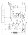
- FIG. 1 is a schematic configuration diagram illustrating a gas turbine engine GT to be controlled by a control method according to an embodiment of the present invention.
- the gas turbine engine GT includes a compressor 1, a single can type main combustor 3, a turbine 5, and a heat exchanger 7.
- the generator 9 is driven by the output of the gas turbine engine GT.
- the gas turbine engine GT in this embodiment mixes low calorie gas such as CMM (Coal Mine Methane) generated in a coal mine with air or VAM (Ventilation Air Methane; coal mine aeration methane) discharged from the coal mine. It is configured as a lean fuel intake gas turbine engine that inhales into the engine and uses contained combustible components as fuel.
- the main combustor 3 is configured as a catalytic combustor including a catalyst such as platinum or palladium.
- the intake gas G1 obtained by mixing the fuel gas in the mixer 11 is introduced from the intake inlet of the compressor 1 into the gas turbine engine GT.
- the mixer 11 is provided in the middle of the fuel introduction path 12 for introducing the CMM from the CMM fuel source Sc into the compressor 1. Further, the flow rate of the CMM fuel is adjusted by a CMM fuel control valve 13 provided on the upstream side of the mixer 11 in the fuel introduction path 12.
- An intake air temperature measuring device T1 for measuring the temperature of the intake gas G1 is provided at the intake air inlet of the compressor 1.
- the intake gas G1 is compressed by the compressor 1, and the high-pressure compressed gas G2 obtained by this compression is sent to the main combustor 3.
- the compressed gas G2 is burned by the catalytic reaction of the main combustor 3 with a catalyst such as platinum or palladium.
- a high-temperature / high-pressure combustion gas G3 generated by combustion of the compressed gas G2 in the main combustor 3 is supplied to the turbine 5 to drive the turbine 5.
- An inlet temperature measuring device T2 and an outlet temperature measuring device T3 are provided at the inlet and the outlet of the main combustor 3, respectively.
- the turbine 5 is connected to the compressor 1 and the generator 9 via the rotary shaft 15, and the compressor 1 and the generator 9 are driven by the turbine 5.
- a rotation detector 18 that measures the number of rotations of the turbine 5 is provided in a portion of the rotating shaft 15 between the compressor 1 and the generator 9.
- the generator 9 is connected to an external power system 19 via a power conversion device 17.
- the power conversion device 17 incorporates a circuit that converts DC power and AC power into each other, and performs bidirectional power supply between the generator 9 and the power system 19.
- the heat exchanger 7 heats the compressed gas G2 introduced from the compressor 1 to the main combustor 3 using the turbine exhaust gas G4 from the turbine 5 as a heating medium.
- the compressed gas G2 from the compressor 1 is sent to the heat exchanger 7 via the compressed gas passage 21, heated by the heat exchanger 7, and then sent to the main combustor 3 via the high-temperature compressed gas passage 25.
- Turbine exhaust gas G 4 that has passed through the main combustor 3 and the turbine 5 flows into the heat exchanger 7 through the turbine exhaust gas passage 29.
- the exhaust gas G5 flowing out from the heat exchanger 7 is silenced through a silencer (not shown) and then released to the outside.
- the gas turbine engine GT has a bleed passage 31 that is branched from the compressed gas passage 21.
- the extraction passage 31 is connected to the exhaust gas passage 29, and part of the compressed gas G ⁇ b> 2 passing through the compressed gas passage 21 is extracted into the exhaust gas passage 29 as necessary.
- a bleed valve 33 that adjusts the flow rate of the compressed gas passing through the bleed passage 31 is provided.
- high-temperature combustion gas is supplied to the heat exchanger 7 on the downstream side of the bleed valve 33 in the bleed passage 31 from when the gas turbine engine GT is started until the main combustor 3 reaches a predetermined operating temperature.
- An auxiliary combustor that supplies and warms up the heat exchanger 7 may be provided.
- the auxiliary combustor is supplied with fuel, for example, CMM, from a dedicated fuel supply path.
- a control device 41 is provided for reducing the above.
- the rotation speed correction unit 43 provided in the control device 41 corrects the rotation speed based on the measurement result of the intake air temperature measuring device T1. Specifically, if the temperature of the intake gas G1 measured by the intake air temperature measuring device T1 is equal to or higher than a predetermined value, the rotational speed correction unit 43 does not correct the rotational speed command value and keeps the rated rotational speed, When the temperature of the intake gas G1 measured by the temperature measuring device T1 is lower than a predetermined value, the rotational speed command value is lowered according to the temperature measurement value of the intake gas G1.
- the rotational speed control unit 45 of the control device 41 receives the command value from the rotational speed correction unit 43 and controls the rotational speed of the generator 9 via the power conversion device 17, so that the gas turbine engine GT Control the number of revolutions. Specifically, a decrease in the rotational speed command value of the rotational speed control unit 45 is performed to decrease the rotational speed of the gas turbine engine GT, thereby preventing a decrease in the inlet temperature of the main combustor 3.
- the rotational speed of the gas turbine engine GT is reduced, the intake amount of the intake gas G1 is reduced, and the fuel-air ratio in the main combustor 3 is increased.
- the outlet temperature of the main combustor 3 and the temperature of the turbine exhaust gas G4 are maintained, and the inlet temperature of the main combustor 3 heated via the heat exchanger 7 is also maintained.
- the control device 41 operates over the entire operation period when the gas turbine engine GT is started and during rated operation, and performs the above-described rotation speed correction according to the measured temperature of the intake gas G1. Furthermore, the control device 41 may be operated before starting (stopping) the gas turbine engine GT, and the rotational speed command value may be corrected according to the intake air temperature.
- the catalyst inlet temperature controller 47 of the control device 41 opens the extraction valve 33.
- the inlet temperature of the main combustor 3 is increased by correcting the degree command value and increasing the opening degree of the extraction valve 33.
- the fuel-air ratio in the main combustor 3 further increases.
- the outlet temperature of the main combustor 3 and the temperature of the turbine exhaust gas G4 are maintained, and the inlet temperature of the main combustor 3 heated via the heat exchanger 7 is maintained.
- the inlet temperature of the catalytic main combustor 3 cannot be maintained even by the above-described rotation speed control.
- the inlet temperature of the main combustor 3 can be reliably maintained.
- the catalyst inlet temperature is maintained by controlling the rotational speed of the lean fuel intake gas turbine engine GT according to the intake air temperature. Therefore, misfiring due to a decrease in the intake air temperature of the catalytic main combustor 3 can be reliably prevented even during start-up, and the operation state of the gas turbine engine GT can be stably maintained.
Landscapes
- Engineering & Computer Science (AREA)
- Chemical & Material Sciences (AREA)
- Combustion & Propulsion (AREA)
- Mechanical Engineering (AREA)
- General Engineering & Computer Science (AREA)
- Control Of Turbines (AREA)
- Exhaust Gas After Treatment (AREA)
- Engine Equipment That Uses Special Cycles (AREA)
- Output Control And Ontrol Of Special Type Engine (AREA)
- Combined Controls Of Internal Combustion Engines (AREA)
- Electrical Control Of Air Or Fuel Supplied To Internal-Combustion Engine (AREA)
Abstract
Description
3 主燃焼器(触媒式燃焼器)
5 タービン
7 熱交換器
9 発電機
17 電力変換装置
31 抽気路
33 抽気弁
41 制御装置
43 回転数補正部
45 回転数制御部
47 触媒入口温度制御部
G1 吸入ガス
GT ガスタービンエンジン
T1 吸気温度計測器
Claims (6)
- 圧縮機で圧縮された圧縮ガスを燃焼させてタービンへ供給する触媒式の燃焼器と、前記タービンからの排ガスを加熱媒体として前記圧縮ガスを加熱する熱交換器とを備え、低濃度メタンガスに含まれている可燃成分を燃料として利用する希薄燃料吸入ガスタービンエンジンを制御する方法であって、
当該ガスタービンエンジンの前記圧縮機に流入する吸入ガスの温度が所定の値よりも低い場合に、前記吸入ガスの温度に応じて当該エンジンの回転数を低下させる、希薄燃料吸入ガスタービンエンジンの制御方法。 - 請求項1に記載の制御方法において、当該ガスタービンエンジンによって駆動される発電機と外部電力との間に電力変換装置を介在させ、前記電力変換装置を介して前記発電機の回転数を下げることにより当該エンジンの回転数を低下させる希薄燃料吸入ガスタービンエンジンの制御方法。
- 請求項1または2に記載の制御方法において、さらに、前記ガスタービンエンジンに、前記圧縮ガスの通路から圧縮ガスを前記排ガスの通路に抽気する抽気路と、この抽気路を通過する抽気ガスの流量を調整する抽気弁とを設け、この抽気弁の開度を上げることにより前記燃焼器の入口温度を上昇させる希薄燃料ガスタービンエンジンの制御方法。
- 圧縮機で圧縮された圧縮ガスを燃焼させてタービンへ供給する触媒式の燃焼器と、前記タービンからの排ガスを加熱媒体として前記圧縮ガスを加熱する熱交換器とを備え、低濃度メタンガスに含まれている可燃成分を燃料として利用する希薄燃料吸入ガスタービンエンジンを制御する装置であって、
当該ガスタービンエンジンの圧縮機に流入する吸入ガスの温度が所定の値よりも低い場合に、前記吸入ガスの温度に応じて当該エンジンの回転数指令値を低下させる回転数補正部を備える希薄燃料吸入ガスタービンエンジンの制御装置。 - 請求項4に記載の制御装置において、さらに、前記回転数補正部からの回転数指令値に基づいて、当該ガスタービンエンジンによって駆動される発電機と外部電力との間に介在する電力変換装置を介して前記発電機の回転数を制御する回転数制御部を備える希薄燃料ガスタービンエンジンの制御装置。
- 請求項4または5に記載の制御装置において、前記ガスタービンエンジンが、前記圧縮ガスの通路から圧縮ガスを前記排ガスの通路に抽気する抽気路と、この抽気路を通過する抽気ガスの流量を調整する抽気弁とを備えており、当該制御装置が、さらに、前記抽気弁の開度を上げることにより前記燃焼器の入口温度を低下させる触媒入口温度制御部を備えている希薄燃料ガスタービンエンジンの制御装置。
Priority Applications (2)
| Application Number | Priority Date | Filing Date | Title |
|---|---|---|---|
| CN201480009898.7A CN105026733B (zh) | 2013-02-22 | 2014-01-10 | 贫燃料吸入燃气轮机的控制方法及控制装置 |
| AU2014220107A AU2014220107B2 (en) | 2013-02-22 | 2014-01-10 | Device and method for controlling lean fuel intake gas turbine |
Applications Claiming Priority (2)
| Application Number | Priority Date | Filing Date | Title |
|---|---|---|---|
| JP2013032828A JP5592965B2 (ja) | 2013-02-22 | 2013-02-22 | 希薄燃料吸入ガスタービンの制御方法および制御装置 |
| JP2013-032828 | 2013-02-22 |
Publications (1)
| Publication Number | Publication Date |
|---|---|
| WO2014129226A1 true WO2014129226A1 (ja) | 2014-08-28 |
Family
ID=51391022
Family Applications (1)
| Application Number | Title | Priority Date | Filing Date |
|---|---|---|---|
| PCT/JP2014/050297 Ceased WO2014129226A1 (ja) | 2013-02-22 | 2014-01-10 | 希薄燃料吸入ガスタービンの制御方法および制御装置 |
Country Status (4)
| Country | Link |
|---|---|
| JP (1) | JP5592965B2 (ja) |
| CN (1) | CN105026733B (ja) |
| AU (1) | AU2014220107B2 (ja) |
| WO (1) | WO2014129226A1 (ja) |
Families Citing this family (1)
| Publication number | Priority date | Publication date | Assignee | Title |
|---|---|---|---|---|
| EP3445955B1 (en) * | 2016-04-21 | 2022-06-22 | 8 Rivers Capital, LLC | System and method for oxidation of hydrocarbon gases |
Citations (2)
| Publication number | Priority date | Publication date | Assignee | Title |
|---|---|---|---|---|
| JP2003090230A (ja) * | 2001-09-17 | 2003-03-28 | Takuma Co Ltd | ガスタービン発電装置及びこれに用いる混合ガス燃焼装置 |
| JP2010019247A (ja) * | 2008-06-13 | 2010-01-28 | Kawasaki Heavy Ind Ltd | 希薄燃料吸入ガスタービン |
Family Cites Families (5)
| Publication number | Priority date | Publication date | Assignee | Title |
|---|---|---|---|---|
| US7278266B2 (en) * | 2004-08-31 | 2007-10-09 | General Electric Company | Methods and apparatus for gas turbine engine lean blowout avoidance |
| CN101560919B (zh) * | 2008-04-18 | 2011-02-02 | 北京时代桃源环境科技有限公司 | 一种低燃烧值气体的发电预处理控制方法 |
| US7895821B2 (en) * | 2008-12-31 | 2011-03-01 | General Electric Company | System and method for automatic fuel blending and control for combustion gas turbine |
| CN201486661U (zh) * | 2009-08-19 | 2010-05-26 | 四川汇特生物开发有限公司 | 可燃气体发电机气体混合自动控制系统 |
| CN103975144A (zh) * | 2011-12-21 | 2014-08-06 | 川崎重工业株式会社 | 贫燃料吸入燃气轮机的控制方法及控制装置 |
-
2013
- 2013-02-22 JP JP2013032828A patent/JP5592965B2/ja not_active Expired - Fee Related
-
2014
- 2014-01-10 AU AU2014220107A patent/AU2014220107B2/en not_active Ceased
- 2014-01-10 CN CN201480009898.7A patent/CN105026733B/zh not_active Expired - Fee Related
- 2014-01-10 WO PCT/JP2014/050297 patent/WO2014129226A1/ja not_active Ceased
Patent Citations (2)
| Publication number | Priority date | Publication date | Assignee | Title |
|---|---|---|---|---|
| JP2003090230A (ja) * | 2001-09-17 | 2003-03-28 | Takuma Co Ltd | ガスタービン発電装置及びこれに用いる混合ガス燃焼装置 |
| JP2010019247A (ja) * | 2008-06-13 | 2010-01-28 | Kawasaki Heavy Ind Ltd | 希薄燃料吸入ガスタービン |
Also Published As
| Publication number | Publication date |
|---|---|
| CN105026733B (zh) | 2017-06-13 |
| JP5592965B2 (ja) | 2014-09-17 |
| AU2014220107B2 (en) | 2016-07-21 |
| CN105026733A (zh) | 2015-11-04 |
| AU2014220107A1 (en) | 2015-10-15 |
| JP2014163243A (ja) | 2014-09-08 |
Similar Documents
| Publication | Publication Date | Title |
|---|---|---|
| JP4751950B1 (ja) | 希薄燃料吸入ガスタービン | |
| JP6662638B2 (ja) | ガスタービン負荷制御システム | |
| US20140291993A1 (en) | Method for operating lean fuel intake gas turbine engine, and gas turbine power generation device | |
| US20140298818A1 (en) | Control method and control device for lean fuel intake gas turbine | |
| RU2566621C2 (ru) | Способ работы газовой турбины с последовательным сгоранием и газовая турбина для осуществления указанного способа | |
| CN103958857B (zh) | 贫燃料吸入燃气轮机 | |
| CN106536899A (zh) | 控制装置、系统以及控制方法 | |
| CN104011347A (zh) | 具备热交换器的燃气涡轮发动机及其启动方法 | |
| WO2013094433A1 (ja) | ガスタービンエンジンとその始動方法 | |
| US20140250857A1 (en) | Low-concentration methane gas oxidation system using exhaust heat from gas turbine engine | |
| AU2012327118B2 (en) | Lean fuel intake gas turbine | |
| JP4452092B2 (ja) | ガスエンジンの燃焼制御方法及びその装置 | |
| JP5592965B2 (ja) | 希薄燃料吸入ガスタービンの制御方法および制御装置 | |
| CN105074169A (zh) | 用于使燃气轮机以低于其额定功率操作的方法 | |
| CN111712618B (zh) | 用于起动联合循环动力装置的燃气涡轮发动机的方法 | |
| JP4795999B2 (ja) | ガスタービン発電システム | |
| JPWO2014002818A1 (ja) | 複数の酸化処理器を備える低濃度メタンガス酸化システム |
Legal Events
| Date | Code | Title | Description |
|---|---|---|---|
| WWE | Wipo information: entry into national phase |
Ref document number: 201480009898.7 Country of ref document: CN |
|
| 121 | Ep: the epo has been informed by wipo that ep was designated in this application |
Ref document number: 14754061 Country of ref document: EP Kind code of ref document: A1 |
|
| NENP | Non-entry into the national phase |
Ref country code: DE |
|
| ENP | Entry into the national phase |
Ref document number: 2014220107 Country of ref document: AU Date of ref document: 20140110 Kind code of ref document: A |
|
| 122 | Ep: pct application non-entry in european phase |
Ref document number: 14754061 Country of ref document: EP Kind code of ref document: A1 |