WO2014129093A1 - Connection-structure manufacturing method, wire harness, and connection-structure manufacturing device - Google Patents
Connection-structure manufacturing method, wire harness, and connection-structure manufacturing device Download PDFInfo
- Publication number
- WO2014129093A1 WO2014129093A1 PCT/JP2013/085226 JP2013085226W WO2014129093A1 WO 2014129093 A1 WO2014129093 A1 WO 2014129093A1 JP 2013085226 W JP2013085226 W JP 2013085226W WO 2014129093 A1 WO2014129093 A1 WO 2014129093A1
- Authority
- WO
- WIPO (PCT)
- Prior art keywords
- crimping
- wire
- crimp
- connection structure
- electric wire
- Prior art date
Links
Images


Classifications
-
- H—ELECTRICITY
- H01—ELECTRIC ELEMENTS
- H01R—ELECTRICALLY-CONDUCTIVE CONNECTIONS; STRUCTURAL ASSOCIATIONS OF A PLURALITY OF MUTUALLY-INSULATED ELECTRICAL CONNECTING ELEMENTS; COUPLING DEVICES; CURRENT COLLECTORS
- H01R4/00—Electrically-conductive connections between two or more conductive members in direct contact, i.e. touching one another; Means for effecting or maintaining such contact; Electrically-conductive connections having two or more spaced connecting locations for conductors and using contact members penetrating insulation
- H01R4/10—Electrically-conductive connections between two or more conductive members in direct contact, i.e. touching one another; Means for effecting or maintaining such contact; Electrically-conductive connections having two or more spaced connecting locations for conductors and using contact members penetrating insulation effected solely by twisting, wrapping, bending, crimping, or other permanent deformation
- H01R4/18—Electrically-conductive connections between two or more conductive members in direct contact, i.e. touching one another; Means for effecting or maintaining such contact; Electrically-conductive connections having two or more spaced connecting locations for conductors and using contact members penetrating insulation effected solely by twisting, wrapping, bending, crimping, or other permanent deformation by crimping
-
- H—ELECTRICITY
- H01—ELECTRIC ELEMENTS
- H01R—ELECTRICALLY-CONDUCTIVE CONNECTIONS; STRUCTURAL ASSOCIATIONS OF A PLURALITY OF MUTUALLY-INSULATED ELECTRICAL CONNECTING ELEMENTS; COUPLING DEVICES; CURRENT COLLECTORS
- H01R4/00—Electrically-conductive connections between two or more conductive members in direct contact, i.e. touching one another; Means for effecting or maintaining such contact; Electrically-conductive connections having two or more spaced connecting locations for conductors and using contact members penetrating insulation
- H01R4/24—Connections using contact members penetrating or cutting insulation or cable strands
- H01R4/2495—Insulation penetration combined with permanent deformation of the contact member, e.g. crimping
-
- H—ELECTRICITY
- H01—ELECTRIC ELEMENTS
- H01R—ELECTRICALLY-CONDUCTIVE CONNECTIONS; STRUCTURAL ASSOCIATIONS OF A PLURALITY OF MUTUALLY-INSULATED ELECTRICAL CONNECTING ELEMENTS; COUPLING DEVICES; CURRENT COLLECTORS
- H01R43/00—Apparatus or processes specially adapted for manufacturing, assembling, maintaining, or repairing of line connectors or current collectors or for joining electric conductors
- H01R43/04—Apparatus or processes specially adapted for manufacturing, assembling, maintaining, or repairing of line connectors or current collectors or for joining electric conductors for forming connections by deformation, e.g. crimping tool
- H01R43/048—Crimping apparatus or processes
- H01R43/05—Crimping apparatus or processes with wire-insulation stripping
-
- H—ELECTRICITY
- H01—ELECTRIC ELEMENTS
- H01R—ELECTRICALLY-CONDUCTIVE CONNECTIONS; STRUCTURAL ASSOCIATIONS OF A PLURALITY OF MUTUALLY-INSULATED ELECTRICAL CONNECTING ELEMENTS; COUPLING DEVICES; CURRENT COLLECTORS
- H01R43/00—Apparatus or processes specially adapted for manufacturing, assembling, maintaining, or repairing of line connectors or current collectors or for joining electric conductors
- H01R43/04—Apparatus or processes specially adapted for manufacturing, assembling, maintaining, or repairing of line connectors or current collectors or for joining electric conductors for forming connections by deformation, e.g. crimping tool
- H01R43/048—Crimping apparatus or processes
- H01R43/052—Crimping apparatus or processes with wire-feeding mechanism
-
- H—ELECTRICITY
- H01—ELECTRIC ELEMENTS
- H01R—ELECTRICALLY-CONDUCTIVE CONNECTIONS; STRUCTURAL ASSOCIATIONS OF A PLURALITY OF MUTUALLY-INSULATED ELECTRICAL CONNECTING ELEMENTS; COUPLING DEVICES; CURRENT COLLECTORS
- H01R4/00—Electrically-conductive connections between two or more conductive members in direct contact, i.e. touching one another; Means for effecting or maintaining such contact; Electrically-conductive connections having two or more spaced connecting locations for conductors and using contact members penetrating insulation
- H01R4/10—Electrically-conductive connections between two or more conductive members in direct contact, i.e. touching one another; Means for effecting or maintaining such contact; Electrically-conductive connections having two or more spaced connecting locations for conductors and using contact members penetrating insulation effected solely by twisting, wrapping, bending, crimping, or other permanent deformation
- H01R4/18—Electrically-conductive connections between two or more conductive members in direct contact, i.e. touching one another; Means for effecting or maintaining such contact; Electrically-conductive connections having two or more spaced connecting locations for conductors and using contact members penetrating insulation effected solely by twisting, wrapping, bending, crimping, or other permanent deformation by crimping
- H01R4/20—Electrically-conductive connections between two or more conductive members in direct contact, i.e. touching one another; Means for effecting or maintaining such contact; Electrically-conductive connections having two or more spaced connecting locations for conductors and using contact members penetrating insulation effected solely by twisting, wrapping, bending, crimping, or other permanent deformation by crimping using a crimping sleeve
-
- H—ELECTRICITY
- H01—ELECTRIC ELEMENTS
- H01R—ELECTRICALLY-CONDUCTIVE CONNECTIONS; STRUCTURAL ASSOCIATIONS OF A PLURALITY OF MUTUALLY-INSULATED ELECTRICAL CONNECTING ELEMENTS; COUPLING DEVICES; CURRENT COLLECTORS
- H01R4/00—Electrically-conductive connections between two or more conductive members in direct contact, i.e. touching one another; Means for effecting or maintaining such contact; Electrically-conductive connections having two or more spaced connecting locations for conductors and using contact members penetrating insulation
- H01R4/58—Electrically-conductive connections between two or more conductive members in direct contact, i.e. touching one another; Means for effecting or maintaining such contact; Electrically-conductive connections having two or more spaced connecting locations for conductors and using contact members penetrating insulation characterised by the form or material of the contacting members
- H01R4/62—Connections between conductors of different materials; Connections between or with aluminium or steel-core aluminium conductors
-
- H—ELECTRICITY
- H01—ELECTRIC ELEMENTS
- H01R—ELECTRICALLY-CONDUCTIVE CONNECTIONS; STRUCTURAL ASSOCIATIONS OF A PLURALITY OF MUTUALLY-INSULATED ELECTRICAL CONNECTING ELEMENTS; COUPLING DEVICES; CURRENT COLLECTORS
- H01R43/00—Apparatus or processes specially adapted for manufacturing, assembling, maintaining, or repairing of line connectors or current collectors or for joining electric conductors
- H01R43/005—Apparatus or processes specially adapted for manufacturing, assembling, maintaining, or repairing of line connectors or current collectors or for joining electric conductors for making dustproof, splashproof, drip-proof, waterproof, or flameproof connection, coupling, or casing
-
- H—ELECTRICITY
- H01—ELECTRIC ELEMENTS
- H01R—ELECTRICALLY-CONDUCTIVE CONNECTIONS; STRUCTURAL ASSOCIATIONS OF A PLURALITY OF MUTUALLY-INSULATED ELECTRICAL CONNECTING ELEMENTS; COUPLING DEVICES; CURRENT COLLECTORS
- H01R43/00—Apparatus or processes specially adapted for manufacturing, assembling, maintaining, or repairing of line connectors or current collectors or for joining electric conductors
- H01R43/04—Apparatus or processes specially adapted for manufacturing, assembling, maintaining, or repairing of line connectors or current collectors or for joining electric conductors for forming connections by deformation, e.g. crimping tool
- H01R43/048—Crimping apparatus or processes
- H01R43/055—Crimping apparatus or processes with contact member feeding mechanism
-
- Y—GENERAL TAGGING OF NEW TECHNOLOGICAL DEVELOPMENTS; GENERAL TAGGING OF CROSS-SECTIONAL TECHNOLOGIES SPANNING OVER SEVERAL SECTIONS OF THE IPC; TECHNICAL SUBJECTS COVERED BY FORMER USPC CROSS-REFERENCE ART COLLECTIONS [XRACs] AND DIGESTS
- Y10—TECHNICAL SUBJECTS COVERED BY FORMER USPC
- Y10T—TECHNICAL SUBJECTS COVERED BY FORMER US CLASSIFICATION
- Y10T29/00—Metal working
- Y10T29/49—Method of mechanical manufacture
- Y10T29/49002—Electrical device making
- Y10T29/49117—Conductor or circuit manufacturing
- Y10T29/49204—Contact or terminal manufacturing
- Y10T29/49208—Contact or terminal manufacturing by assembling plural parts
- Y10T29/4922—Contact or terminal manufacturing by assembling plural parts with molding of insulation
-
- Y—GENERAL TAGGING OF NEW TECHNOLOGICAL DEVELOPMENTS; GENERAL TAGGING OF CROSS-SECTIONAL TECHNOLOGIES SPANNING OVER SEVERAL SECTIONS OF THE IPC; TECHNICAL SUBJECTS COVERED BY FORMER USPC CROSS-REFERENCE ART COLLECTIONS [XRACs] AND DIGESTS
- Y10—TECHNICAL SUBJECTS COVERED BY FORMER USPC
- Y10T—TECHNICAL SUBJECTS COVERED BY FORMER US CLASSIFICATION
- Y10T29/00—Metal working
- Y10T29/53—Means to assemble or disassemble
- Y10T29/5313—Means to assemble electrical device
- Y10T29/532—Conductor
- Y10T29/53209—Terminal or connector
- Y10T29/53213—Assembled to wire-type conductor
- Y10T29/53235—Means to fasten by deformation
Definitions
- connection structure manufacturing method for example, a connection structure manufacturing method, a connection structure manufacturing apparatus, and a connection structure, which are configured by connecting a closed barrel type crimp terminal and a covered electric wire whose conductor is covered with an insulating coating. It relates to the used wire harness.
- An electrical component equipped in an automobile or the like constitutes an electric circuit by being connected to another electrical component or a power supply device via a wire harness in which covered electric wires are bundled.
- the wire harness, the electrical component, and the power supply device are connected by male-female fitting of the connectors attached to each.
- a connection structure in which a crimp terminal and a covered electric wire are crimped and connected is mounted inside the connector. This connection structure connects the crimping terminal and the covered wire so that they can be connected by crimping the crimping part after inserting the coated wire into the crimping terminal that has a crimping part that electrically connects the conductor of the covered wire. Configured.
- Patent Document 2 As a closed barrel type crimp terminal, for example, there is one disclosed in Patent Document 2. As disclosed in FIG. 10 to FIG. 15 of Patent Document 2, the crimp terminal of Patent Document 2 has a cylindrical crimp part with the other end closed on one side in the longitudinal direction. By inserting and crimping the tip end portion of the covered electric wire into this cylindrical crimp portion, the crimp terminal of Patent Document 2 ensures conduction between the crimp terminal and the conductor of the covered wire, and crimping at the crimp connection portion. It is considered that corrosion occurring on the surface of the part and the surface of the conductor can be prevented.
- a crimp terminal having such a shape cannot be obtained unless it is manufactured by a method such as casting. That is, it is not possible to manufacture a crimp terminal by punching a strip-shaped copper plate and bending it sequentially while being conveyed. Furthermore, a connection structure cannot be configured by connecting a covered electric wire while manufacturing a crimp terminal. For this reason, in the closed barrel type crimp terminal as in Patent Document 2, there is a problem that the connection structure cannot be manufactured continuously and efficiently.
- the present invention relates to a method for manufacturing a connection structure, a wire harness, and a manufacture of a connection structure, in which a conductor portion is securely crimped with a closed barrel-type crimp portion and a connection structure having stable conductivity is efficiently manufactured.
- An object is to provide an apparatus.
- the present invention permits a crimped connection between a coated electric wire provided with a wire tip portion in which a conductor is covered with an insulating coating, the insulating coating on the tip side is peeled off and the conductor on the tip side is exposed, and the wire tip portion.
- the crimp terminal is connected along the short direction of the carrier, and a carrier cutting step of separating the crimp terminal from a terminal connection band in which a plurality of the crimp terminals are connected at a predetermined interval in the longitudinal direction of the carrier, A wire insertion step of inserting at least the wire tip of the covered wire into the crimp portion of the crimp terminal separated from the carrier, and crimping the crimp portion into which the wire tip is inserted.
- a crimping step of crimping connection characterized in that it is a manufacturing apparatus for performing the and the process carried out in this order.
- the crimp terminal is a closed barrel type terminal having a crimp section with a hollow cross-section, and a connection terminal having a connection section that allows connection with the connection section of the other terminal in a pair of terminal sets, or only the crimp section Including a terminal constituted by
- connection structure manufacturing method and the connection structure manufacturing apparatus insert a covered electric wire into a crimp terminal separated from a terminal connection band and crimp it, for example, by a method such as casting.
- the crimp terminal which manufactures this alone is used, the crimp terminal into which the covered electric wire is inserted can be supplied efficiently. For this reason, the manufacturing method of a connection structure and the manufacturing apparatus of a connection structure can manufacture a connection structure efficiently.
- connection direction is different from the insertion direction of the covered electric wire to the crimping part.
- the separating means when separating the crimp terminal from the terminal connection band does not interfere with the insertion of the covered electric wire into the crimp part, and the insertion of the covered electric wire into the crimp part and the Separation of the crimp terminal can be performed simultaneously.
- the connecting direction of the crimping terminal with respect to the carrier and the insertion direction of the covered electric wire into the crimping part are the same direction.
- Separating means for separating the crimp terminal from the connection band hinders the insertion of the covered electric wire into the closed barrel type crimp part.
- connection structure since the manufacturing method of the connection structure and the manufacturing apparatus of the connection structure insert the covered electric wire into the crimp terminal separated from the terminal coupling band and perform the crimping, the separating unit inserts the covered electric wire into the crimp portion.
- the connection structure can be efficiently manufactured without hindering the operation.
- the manufacturing method of the connection structure and the manufacturing apparatus of the connection structure can efficiently manufacture the connection structure having stable conductivity by securely crimping the conductor portion with the closed barrel type crimping portion. it can.
- the covering strip step of peeling off the insulating coating on the tip end side of the covered electric wire arranged at a predetermined position to constitute the electric wire tip portion can be performed prior to the carrier cutting step.
- connection structure can be manufactured more efficiently. More specifically, the method for manufacturing a connection structure and the apparatus for manufacturing a connection structure include a carrier-cutting process in which a coating strip process is performed in which the insulating coating on the tip side of the covered wire arranged at a predetermined position is peeled off to form the wire tip. Performing prior to the process, that is, once the covered electric wire is arranged in a predetermined arrangement, it is possible to configure the wire tip portion where the conductor is exposed and to perform a series of subsequent steps.
- the manufacturing method of the connection structure and the manufacturing apparatus of the connection structure can perform the subsequent steps continuously, for example, by once setting the covered electric wire to be stripped at a predetermined position. For this reason, the manufacturing method of a connection structure and the manufacturing apparatus of a connection structure can manufacture a connection structure further efficiently.
- a marking step of marking a mark at a predetermined position according to the insertion length of the wire tip portion into the crimp portion in the insulating coating is performed between the coating strip step and the carrier cutting step.
- an inspection step of inspecting the crimping state of the wire tip to the crimping portion can be performed using the mark.
- Inspecting the above crimping state means, for example, the insertion length of the wire tip with respect to the closed barrel type crimping portion, that is, whether or not the wire tip can be inserted to a predetermined position, folded without being inserted into the crimping portion.
- This is related to the quality of the connection structure such as conductivity and durability, such as inspection of the presence or absence of wires coming out from the crimping part, or inspection of whether or not the coated electric wire is bent and crimped to the crimping part.
- the inspection includes visual inspection and, for example, mechanical inspection based on detection by image processing or a sensor.
- connection structure that can reliably obtain conductivity, durability, and the like.
- a positional deviation may occur between the tip of the insulating coating and the tip of the conductor. Therefore, when the marking process is performed before the covering strip process, the position of the mark after the covering strip process is different from the desired position by determining the predetermined position based on the length from the tip of the insulating coating. The insertion length of the wire tip portion with respect to the crimping portion is insufficient, and there is a possibility that a connection structure that ensures stable conductivity cannot be manufactured.
- connection structure manufacturing method and the connection structure manufacturing apparatus determine a predetermined position based on the length from the tip of the wire tip. Therefore, the mark can be accurately marked at a desired position.
- the crimping state of the wire tip to the crimping part is inspected.
- the wire tip can be inserted to a predetermined position with respect to the closed barrel crimping part.
- a problem that causes a decrease in conductivity such as being crimped in a state where a part of the wire constituting the conductor is caught and folded,
- the manufacturing method of the connection structure and the manufacturing apparatus of the connection structure can be easily determined by using the mark marked on the insulating coating.
- the manufacturing method of the connection structure and the manufacturing apparatus of the connection structure are marked on the insulating coating for defects that cause a decrease in durability, such as the coated wire being bent and crimped to the crimping portion. It can be easily distinguished by using a mark. Therefore, the manufacturing method of the connection structure and the manufacturing apparatus of the connection structure can manufacture a high-quality connection structure that can reliably obtain conductivity, durability, and the like.
- the conductor can be made of an aluminum-based material, and at least the pressure-bonding portion can be made of a copper-based material.
- the copper-based material can be composed of copper, copper alloy, etc.
- the conductor composed of the aluminum-based material is composed of aluminum or aluminum alloy core wire or stranded wire twisted. Can do.
- the present invention it is possible to reduce the weight as compared to a covered electric wire having a conductor made of copper wire, and to efficiently manufacture a connection structure having stable conductivity.
- the copper-based material conventionally used for the conductor of the covered wire is replaced with an aluminum-based material such as aluminum or aluminum alloy, and the conductor made of the aluminum-based material is crimped to the crimp terminal, the terminal material is tin-plated
- a base metal such as an aluminum material is corroded by contact with a noble metal such as gold plating or copper alloy, that is, electrolytic corrosion may be a problem.
- electrolytic corrosion is a phenomenon in which when a moisture adheres to a site where a noble metal and a base metal are in contact, a corrosion current is generated, and the base metal is corroded, dissolved, or lost. Due to this phenomenon, the conductor made of an aluminum-based material that is crimped to the crimping portion of the crimping terminal is corroded, dissolved, or lost, and eventually the electrical resistance increases. As a result, there is a problem that a sufficient conductive function cannot be achieved.
- connection structure manufacturing method can manufacture a connection structure capable of ensuring a stable conductivity by reducing the weight regardless of the metal species constituting the conductor of the covered electric wire.
- the present invention is a wire harness in which a plurality of connection structures manufactured by the above-described connection structure manufacturing method are bundled, and crimp terminals in the connection structure are mounted in a connector housing.
- the wire harness which ensured favorable electroconductivity can be comprised with the connection structure manufactured efficiently.
- connection structure a connection structure having stable conductivity by securely crimping a conductor portion with a closed barrel-type crimp portion
- An apparatus can be provided.
- FIG. 4 is a cross-sectional view taken along arrow AA in FIG. 3.
- the top view which shows the external appearance from the upper direction in a manufacturing apparatus.
- the flowchart which shows operation
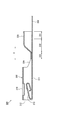
- the external appearance perspective view which shows the connection corresponding
- the top view which shows the external appearance from the upper direction in the manufacturing apparatus of another connection structure.
- the top view which shows the external appearance from the upper direction in the manufacturing apparatus of another connection structure.
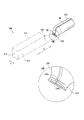
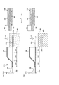
- FIG. 1 is an explanatory view for explaining the connection structure 1
- FIG. 2 is an explanatory view for explaining welding in the crimping portion 230
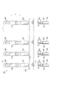
- FIG. 3 is a plan view from above of the terminal connection band 300 and the covered electric wire 100
- FIG. 4 is a cross-sectional view taken along line AA in FIG.
- FIG. 1A shows an external perspective view of the connection structure 1 from the front upper view
- FIG. 1B shows the covered electric wire 100 and the crimp terminal 200 constituting the connection structure 1 from the front upper view. The external appearance perspective view is shown.
- an arrow X indicates the front-rear direction (hereinafter referred to as “front-rear direction X”)
- an arrow Y indicates the width direction (hereinafter referred to as “width direction Y”).
- front-rear direction X the box part 210 side (left side in FIG. 1) described later is defined as the front, and the covered electric wire 100 side (right side in FIG. 1) described later with respect to the box part 210 is defined as the rear.
- the upper side in FIG. 1 is the upper side
- the lower side in FIG. 1 is the lower side.
- the connection structure 1 is configured by crimping and connecting a covered electric wire 100 and a crimp terminal 200.
- the covered electric wire 100 is configured by covering an aluminum core wire 101 in which a plurality of aluminum wires 101a are bundled with an insulating coating 102 made of an insulating resin.
- the aluminum core wire 101 is formed by twisting an aluminum alloy wire so that the cross section is 0.75 mm 2 .
- the covered electric wire 100 constitutes the electric wire tip portion 103 by peeling off the insulating coating 102 by a predetermined length in the front-rear direction X from the tip to expose the aluminum core wire 101.
- a substantially linear mark 104 is provided in the circumferential direction of the covered electric wire 100 at a position of a predetermined length from the tip of the electric wire tip 103 on the upper surface of the insulating coating 102 in the covered electric wire 100. The mark 104 will be described in detail later.
- the crimp terminal 200 is a female terminal, and allows insertion of male tabs of male terminals (not shown) from the front to the rear in the front-rear direction X.
- the box portion 210 and the crimping portion 230 disposed behind the box portion 210 via a transition portion 220 having a predetermined length are integrally configured.
- the crimp terminal 200 is formed by punching a copper alloy strip (not shown) such as brass whose surface is tin-plated (Sn-plated) into a planarly expanded terminal shape, and then rearwardly viewing the box portion 210 of the hollow rectangular column body.
- the closed barrel type terminal is formed by bending into a three-dimensional terminal shape composed of a substantially O-shaped crimping portion 230 and welding the crimping portion 230.
- the box part 210 overlaps one end of the side part 212 connected to both side parts in the width direction Y orthogonal to the front-rear direction X of the bottom part 211 on the other end part. And is formed of a substantially rectangular inverted hollow quadrangular prism body as viewed from the front side in the front-rear direction X.
- an insertion tab of a male terminal is formed in the box portion 210 by extending the front side in the front-rear direction X of the bottom surface portion 211 and bending it toward the rear in the front-rear direction X.
- the elastic contact piece 213 that contacts (not shown) is provided (see FIG. 4).
- the crimping portion 230 includes a coating crimping portion 231 that crimps the insulating coating 102, a conductor crimping portion 232 that crimps the wire tip portion 103, and a front end from the conductor crimping portion 232.
- transformed so that a part may be crushed in substantially flat form is comprised integrally.
- the crimping portion 230 has a copper alloy strip punched into a terminal shape that is substantially the same as the outer diameter of the covered electric wire 100 or has an inner diameter slightly larger than the outer diameter of the covered electric wire 100.
- the rounded end portions 230a and 230b are brought into contact with each other and welded along the welding point W1 in the front-rear direction X to form a substantially O-shape in rear view.
- the crimping part 230 forms the cross-sectional shape in the width direction Y into a closed cross-sectional shape.
- the sealing portion 233 of the crimping portion 230 is welded and sealed along the welding portion W2 in the width direction Y so as to close the front end of the crimping portion 230 in the front-rear direction X. It has stopped. That is, the crimping portion 230 is formed in a substantially cylindrical shape having a front end in the front-rear direction X and end portions 230 a and 230 b being welded and closed, and having an opening at the rear in the front-rear direction X.
- a plurality of such crimp terminals 200 are connected to a substantially band-shaped carrier 250 whose longitudinal direction is the width direction Y of the crimp terminal 200 to constitute a terminal connection band 300. More specifically, as shown in FIGS. 3 and 4, the terminal connection band 300 is a short direction perpendicular to the longitudinal direction of the carrier 250 with respect to the longitudinal direction X that is the longitudinal direction of the crimp terminal 200 in plan view. Are connected to the carrier 250 at the rear lower end of the crimping portion 230 in the crimp terminal 200. The terminal connection band 300 connects the plurality of crimp terminals 200 with a predetermined interval in the longitudinal direction of the carrier 250.
- This terminal connection band 300 is formed by three-dimensionally forming a terminal shape portion in a copper alloy strip formed by punching a substantially flat copper alloy strip and connecting the substantially strip-shaped carrier 250 and the terminal shape portion developed in a plane. By bending into a simple terminal shape, a state in which a plurality of crimp terminals 200 are connected is configured.
- a manufacturing apparatus 10 for manufacturing the connection structure 1 by crimping and connecting the covered electric wire 100 to the crimp terminal 200 in the terminal connection band 300 and a manufacturing process for manufacturing the connection structure 1 will be described with reference to FIGS. Will be described in detail.
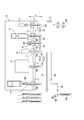
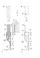
- FIG. 5 shows a plan view from above in the manufacturing apparatus 10
- FIG. 6 shows a flowchart of the operation of the manufacturing process
- FIG. 7 shows an explanatory diagram for explaining the carrier cutting process in the crimping process section 15
- FIG. 9 shows an explanatory diagram for explaining the electric wire insertion process in the crimping process section 15, and
- FIG. 9 shows an explanatory diagram for explaining the crimping process in the crimping process section 15.
- a transport process of transporting the covered wire 100 and the connection structure 1 to the next process by the transport process unit 17 described later is performed between the processes. Shall be done.
- FIG. 7A shows a cross-sectional view of the first stage in the carrier cutting process
- FIG. 7B shows a cross-sectional view of the final stage in the carrier cutting process
- FIG. 8A shows a cross-section in the wire insertion process
- 8 (b) shows a side view in the wire insertion process
- FIG. 9 (a) shows a sectional view in the first stage in the crimping process
- FIG. 9 (b) shows a sectional view in the final stage in the crimping process.
- the figure is shown.
- the box part 210 in the crimp terminal 200 is not shown in order to clarify the main part.
- the manufacturing apparatus 10 that manufactures the connection structure 1 includes a tip detection process unit 11, a covering strip process unit 12, a marking process unit 13, an inspection process unit 14, and a crimping process unit. 15 and the defective product removal process section 16 are arranged in this order.
- the manufacturing apparatus 10 includes a transfer process unit 17 that is configured to be movable between the tip detection process unit 11 and the defective product removal process unit 16 and that is a transfer unit that transfers the covered electric wire 100 and the connection structure 1. I have.
- the tip detection process part 11 is comprised with a contact sensor etc., and has the function to detect the position of the front-end
- the covering strip process part 12 is comprised by the moving mechanism (illustration omitted) etc. which move the covering removal blade type
- the insulation coating 102 having a predetermined length is removed from the tip of the conveyed covered electric wire 100 to expose the aluminum core wire 101.
- the marking process unit 13 includes a paint tank (not shown), a jet outlet (not shown) for jetting paint, and the like, and has a function of jetting paint to a predetermined position on the covered electric wire 100 to mark a mark. is doing.
- the inspection process unit 14 is configured by an image sensor (not shown) and the like, captures the vicinity of the tip of the conveyed covered electric wire 100 from above, obtains image data, and in the covered electric wire 100 based on the imaged image data. It has a function of detecting the state near the tip.
- the crimping process section 15 includes a transport mechanism (not shown) for transporting the terminal connection band 300, a holding mechanism (not shown) for holding the box section 210, a crimping blade mold 41 (see FIG. 9) for crimping the crimping section 230, and a terminal.
- a separation blade mold 40 (see FIG. 7) that separates the crimp terminal 200 from the connection band 300, a moving mechanism (not shown) that moves the crimp blade 41 and the separation blade mold 40 in a predetermined direction, and the like.
- the crimping process unit 15 has a function of transporting the terminal connection band 300, a function of separating the crimp terminal 200 from the transported terminal connection band 300, and a function of crimping the covered electric wire 100 inserted into the crimping unit 230. Have.
- the crimping blade mold 41 is composed of an upper blade mold 41 a and a lower blade mold 41 b that are divided into upper and lower parts, and when combined in the vertical direction, the outer shape of the crimping section 230 in the crimped state is obtained. It is formed in a corresponding inner surface shape.
- the separation blade mold 40 has a substantially rectangular cross section that partially closes the opening of the crimping portion 230 in the crimp terminal 200, and is a slit through which the carrier 250 of the terminal connection band 300 is inserted. It is formed in a shape having a portion 40a.
- the defective product removal process unit 16 includes a cutting blade mold (not shown) that cuts the covered electric wire 100, a moving mechanism (not shown) that moves the cutting blade mold in a predetermined direction, and the like. It has a function of cutting the covered electric wire 100 in the determined connection structure 1.
- the conveyance process part 17 is comprised with the holding mechanism (illustration omitted) holding the covered electric wire 100, the moving mechanism (illustration omitted) which moves a holding mechanism, etc., the function to hold
- the conveyance process part 17 detects the front-end
- the transport process unit 17 moves the covered electric wire 100 in the transport direction C1 and transports it to the tip detection process unit 11 as shown in FIG.
- the manufacturing apparatus 10 starts the electric wire set process which determines the position of the covered electric wire 100 with respect to the manufacturing apparatus 10 in the front-back direction X, as shown in FIG. 6 (step S21).
- indication of the manufacturing apparatus 10 is the front in the front-back direction X of the covered electric wire 100, ie, front-end
- the covered electric wire 100 is moved toward the process unit 11.
- the transfer process unit 17 moves the covered electric wire 100 in the transfer direction C ⁇ b> 2 while maintaining the position in the front-rear direction X with respect to the manufacturing apparatus 10, and the covered strip process unit 12. Transport to.
- the manufacturing apparatus 10 starts a coated strip process for stripping the insulating coating 102 of the coated electric wire 100 as shown in FIG. 6 (step S22). Specifically, the coated strip process unit 12 moves toward the coated electric wire 100 fixed by the conveying process unit 17 according to an instruction from the manufacturing apparatus 10, and at the position of a predetermined length from the tip of the coated electric wire 100. Hold with a mold.
- the covering strip process part 12 moves in a direction away from the covered electric wire 100, thereby peeling off a part of the insulating covering 102 with a covering removal blade mold to expose the aluminum core wire 101 to form the electric wire tip 103.
- the conveyance process unit 17 moves the covered electric wire 100 in the conveyance direction C3 while maintaining the position in the front-rear direction X with respect to the production apparatus 10, as shown in FIG. To the marking process section 13.
- the manufacturing apparatus 10 starts a marking process for applying the mark 104 to the insulating coating 102 as shown in FIG. 6 (step S23). Specifically, the marking process unit 13 detects a position of a predetermined length in the front-rear direction X from the tip of the wire tip 103 according to an instruction from the manufacturing apparatus 10 and applies paint in the circumferential direction of the covered wire 100 at the position. Thus, the mark 104 is formed.
- the position of a predetermined length from the wire tip portion 103 is the position of the insulating coating 102 corresponding to the inner rear end of the crimp portion 230 when the covered wire 100 is inserted into the crimp portion 230.
- the transport process unit 17 instructs the manufacturing apparatus 10 to move the covered wire 100 in the transport direction C ⁇ b> 4 while maintaining the position in the front-rear direction X with respect to the manufacturing apparatus 10 as shown in FIG. 5. It is moved and conveyed to the inspection process unit 14.
- the manufacturing apparatus 10 starts a strip miss detection process for detecting the state of the covered strip as shown in FIG. 6 (step S24). Specifically, as illustrated in FIG. 5, the inspection process unit 14 takes an image of the vicinity of the tip of the covered electric wire 100 and acquires it as image data according to an instruction from the manufacturing apparatus 10. , Or the degree of scatter of the aluminum core wire 101 at the wire tip 103 is detected.
- the manufacturing apparatus 10 excludes the covered electric wire 100 when there is a defect such that the desired length of the insulating coating 102 is not removed, in other words, the length of the electric wire tip 103 is not the desired length.
- the conveyance process unit 17 maintains the position in the front-rear direction X with respect to the manufacturing apparatus 10 as shown in FIG.
- the covered electric wire 100 is moved in the conveyance direction C5 as it is and conveyed to the crimping process unit 15.
- the manufacturing apparatus 10 starts the carrier cut process which isolate
- the crimping process unit 15 conveys the terminal connection band 300 to the inside of the crimping process unit 15 and opens the crimping unit 230 of the crimping terminal 200 according to an instruction from the manufacturing apparatus 10.
- the terminal coupling band 300 is conveyed so that the coated wire 100 and the covered wire 100 face each other.
- the crimping process section 15 conveys the carrier 250 of the terminal coupling band 300 through the slit section 40a of the separating blade mold 40. Thereafter, after holding the box part 210, the crimping process part 15 moves the separation blade die 40 in the separation direction F1 as shown in FIG. 7B, and moves the carrier 250 in the separation direction F1 by the slit part 40a. Press. As a result, the crimping process section 15 separates the crimp terminal 200 and the carrier 250 by cutting the carrier 250 from the terminal connection band 300 so as to shear.
- the manufacturing apparatus 10 starts an electric wire insertion process of inserting the covered electric wire 100 into the crimp terminal 200 as shown in FIG. 6 (step S26). Specifically, the conveyance process unit 17 moves the covered electric wire 100 by a predetermined distance toward the front in the front-rear direction X as shown in FIG. The covered electric wire 100 is inserted into the crimping portion 230 of the crimping terminal 200 that has been formed.
- the transporting process unit 17 aligns the radial center of the covered electric wire 100 with the radial center of the crimping unit 230, or the radial center of the crimping unit 230 via a separate guide member or the like.
- the covered electric wire 100 is inserted into the crimping portion 230 so that the radial center of the covered electric wire 100 substantially coincides.
- tip part 103 of the covered electric wire 100 is normally inserted with respect to the crimp part 230 of the crimp terminal 200, as shown in FIG.8 (b), the mark 104 of the covered electric wire 100 is the crimp part 230. It will be located inside.
- the manufacturing apparatus 10 starts a crimping process for crimping the crimping terminal 200 holding the box part 210 and the covered electric wire 100 as shown in FIG. S27).
- the crimping process unit 15 holds the crimping unit 230 with the crimping blade mold 41 moved in the crimping direction F2, as shown in FIGS.
- the wire tip 103 and the conductor crimping portion 232 are crimped and connected so as to be conductive, and the covering crimping portion 231 is crimped to constitute the connection structure 1.
- the crimping process unit 15 releases the holding of the box unit 210.
- the transport process unit 17 moves the connection structure 1 in the transport direction C6 as shown in FIG. To the inspection process unit 14.
- the manufacturing apparatus 10 starts an inspection process for determining whether or not the crimping state of the connection structure 1 is normal as shown in FIG. Step S28). Specifically, in accordance with an instruction from the manufacturing apparatus 10, the inspection process unit 14 captures an image of the vicinity of the crimping unit 230 of the connection structure 1 and obtains it as image data, and the crimping state of the crimping unit 230 based on the acquired image data. Detect good or bad.
- the presence or absence of a crack in the crimping portion 230 is detected from the image data, and if there is a crack, it is determined that the crimping is defective.
- the mark 104 is exposed from the crimping portion 230, the insertion failure of the covered wire 100 with respect to the crimping portion 230 is short, and the crimping failure is caused by crimping in a state where the wire tip portion 103 does not reach the conductor crimping portion 232 Is determined.
- it compares with each predetermined value, and determines the quality of a crimping state.
- step S29 If the crimping state of the connection structure 1 is normal (step S29: Yes), the manufacturing apparatus 10 determines that the connection structure 1 is a normal product and discharges the connection structure 1 from the manufacturing apparatus 10. Is started (step S30). In detail, the conveyance process part 17 moves the connection structure 1 to the conveyance direction C7 by the instruction
- step S29: No if the crimping state of the connection structure 1 is defective (step S29: No), the conveyance process unit 17 moves the connection structure 1 in the conveyance direction C8 as shown in FIG. Then, it is conveyed to the defective product removal process section 16.
- the manufacturing apparatus 10 starts a defective product removal process that separates and removes the connection structure 1 from the normal product (step S31). More specifically, as shown in FIG. 5, the defective product removal process unit 16 moves toward the covered electric wire 100 fixed by the transport process unit 17 according to an instruction from the manufacturing apparatus 10 and at a predetermined position from the tip of the connection structure 1. The coated electric wire 100 at the position of the length is cut with a cutting blade die, and the crimp terminal 200 in the crimped state is separated.
- the conveyance process part 17 moves the covered electric wire 100 by which the crimp terminal 200 was cut
- the connection structure 1 sorted based on the quality of the crimped state is discharged to a predetermined location and the crimping connection between all the crimp terminals 200 and the covered electric wires 100 is completed, the manufacturing apparatus 10 ends the manufacturing process.
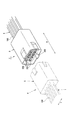
- FIG. 10 shows the external appearance perspective view of the connection corresponding state of the wire harness 2 and the wire harness 4, and has shown the wire harness 4 with the dashed-two dotted line in FIG.
- the wire harness 2 includes a plurality of connection structures 1 and a female connector housing 3.
- the female connector housing 3 has a plurality of cavities in which the crimp terminals 200 can be mounted along the longitudinal direction X, and is formed in a box shape having a substantially rectangular cross section in the width direction Y.
- a plurality of connection structures 1 composed of the above-described crimp terminals 200 are attached along the longitudinal direction X to the inside of the female connector housing 3 to constitute the wire harness 2.
- the wire harness 4 in which the male and female wire harnesses 2 are fitted includes a male connector housing 5 corresponding to the female connector housing 3, and, like the female connector housing 3, a plurality of openings into which crimp terminals can be attached are internally provided. And the cross-sectional shape in the width direction Y is substantially rectangular, and can be connected to the female connector housing 3 corresponding to the unevenness.
- the wire harness 4 is configured by attaching the connection structure 1 constituted by male crimp terminals (not shown) along the longitudinal direction X to the inside of such a male connector housing 5. And the wire harness 2 and the wire harness 4 are connected by fitting the female connector housing 3 and the male connector housing 5.
- the manufacturing method of the connecting structure 1 and the manufacturing apparatus 10 of the connecting structure 1 that realizes the above-described operation reliably crimps the wire tip portion 103 with the closed barrel-type crimping portion 230, thereby providing stable conductivity. Can be efficiently manufactured.
- the manufacturing method of the connection structure 1 and the manufacturing apparatus 10 of the connection structure 1 insert the covered electric wire 100 into the crimp terminal 200 separated from the terminal connection band 300 and crimp it, for example, Compared with the case of using crimp terminals that are individually manufactured by a method such as casting, the crimp terminal 200 into which the covered electric wire 100 is inserted can be supplied efficiently. For this reason, the manufacturing method of the connection structure 1 and the manufacturing apparatus 10 of the connection structure 1 can manufacture the connection structure 1 efficiently.
- connection direction and the insertion direction of the covered electric wire 100 to the crimping portion are different.
- the separation blade mold 40 when separating the crimp terminal from the terminal connection band does not interfere with the insertion of the coated electric wire 100 into the crimp part, and the insertion of the covered electric wire 100 into the crimp part and the terminal Separation of the crimp terminal from the connecting band can be performed simultaneously.
- the connection direction of the crimp terminal 200 with respect to the carrier 250 and the insertion direction of the covered electric wire 100 into the crimp part 230 Since it becomes the same direction, the separating blade mold 40 when separating the crimp terminal 200 from the terminal connection band 300 hinders the insertion of the covered electric wire 100 into the crimp part 230 of the closed barrel type. In addition, it is also difficult to separate the closed barrel type crimping part 230 into which the covered electric wire 100 is inserted from the terminal connection band 300 without damaging the covered electric wire 100 by the separating blade die 40.
- connection structure 1 since the manufacturing method 10 of the connection structure 1 and the manufacturing apparatus 10 of the connection structure 1 insert the covered electric wire 100 into the crimp terminal 200 separated from the terminal connection band 300 and perform crimping, the separation blade mold 40 is provided.
- the connection structure 1 can be efficiently manufactured without hindering the insertion of the covered electric wire 100 into the crimping portion 230.
- connection structure 1 and the manufacturing apparatus 10 of the connection structure 1 securely connect the wire tip 103 with the closed barrel-type crimping portion 230 and have stable conductivity. Can be manufactured efficiently.
- connection structure 1 can be manufactured more efficiently by performing the covering strip process prior to the carrier cutting process. More specifically, the manufacturing method of the connection structure 1 and the manufacturing apparatus 10 of the connection structure 1 peel off the insulating coating 102 on the distal end side of the covered electric wire 100 arranged at a predetermined position to form the electric wire distal end portion 103.
- the stripping process is performed prior to the carrier cutting process, that is, once the covered electric wire 100 is arranged in a predetermined arrangement, the electric wire tip portion 103 where the aluminum core wire 101 is exposed can be formed, and the subsequent series of processes can be performed.
- the manufacturing method of the connection structure 1 and the manufacturing apparatus 10 of the connection structure 1 can perform the subsequent processes continuously only by once setting the covered electric wire 100 to be stripped at a predetermined position, for example. it can. For this reason, the manufacturing method of the connection structure 1 and the manufacturing apparatus 10 of the connection structure 1 can manufacture the connection structure 1 more efficiently.
- connection structure 1 which can obtain conductivity, durability, etc. reliably by performing a marking process between a covering strip process and a carrier cut process, and performing an inspection process after a crimping process.
- a positional deviation may occur between the tip of the insulating coating 102 and the tip of the aluminum core wire 101.
- the marking process is performed before the coating strip process, the position of the mark 104 after the coating strip process is different from the desired position by determining the predetermined position based on the length from the tip of the insulating coating 102. Therefore, there is a possibility that the connection structure 1 that secures stable conductivity cannot be manufactured due to the short insertion length of the wire tip portion 103 with respect to the crimping portion 230.
- the manufacturing method of the connection structure 1 and the manufacturing apparatus 10 of the connection structure 1 are arranged at predetermined positions based on the length from the tip of the wire tip portion 103. Therefore, the mark 104 can be accurately marked at a desired position.
- the mark 104 marked in the marking step is used to inspect the crimping state of the wire tip portion 103 to the crimping portion 230.
- the wire tip to a predetermined position with respect to the closed barrel crimping portion 230 is used.
- the portion 103 has not been inserted, or when the wire tip portion 103 is inserted into the crimping portion 230, the aluminum core wire 101a constituting the aluminum core wire 101 is partly hooked and folded in a crimped state.
- the manufacturing method of the connection structure 1 and the manufacturing apparatus 10 of the connection structure 1 can easily discriminate the trouble that causes the decrease in conductivity by using the mark 104 marked on the insulating coating 102 part. it can.
- the manufacturing method of the connection structure 1 and the manufacturing apparatus 10 of the connection structure 1 are subject to problems that cause a decrease in durability, such as the covered electric wire 100 being bent and crimped to the crimp portion 230. It can be easily determined by using the mark 104 marked on the insulating coating 102 part. Therefore, the manufacturing method of the connection structure 1 and the manufacturing apparatus 10 of the connection structure 1 can manufacture the high-quality connection structure 1 that can reliably obtain conductivity, durability, and the like.
- the conductor of the covered electric wire 100 is made of an aluminum alloy
- the crimping portion 230 is made of a copper alloy, thereby reducing the weight as compared with the covered electric wire having a conductor made of copper wire and providing stable conductivity. It is possible to efficiently manufacture the connection structure 1 having the same.
- the manufacturing method of the connection structure 1 can manufacture the connection structure 1 which prevents what is called electrolytic corrosion, achieving weight reduction compared with the covered electric wire 100 which has the conductor by a copper alloy. Therefore, the manufacturing method of the connection structure 1 can manufacture the connection structure 1 which can be reduced in weight and can ensure stable conductivity irrespective of the metal species constituting the conductor of the covered electric wire 100.
- connection structure 1 manufactured by the above-described method for manufacturing the connection structure 1 are bundled, and the crimp terminal 200 in the connection structure 1 is mounted in the female connector housing 3, thereby providing stable conductivity.
- wire harness 2 that ensures good conductivity can be configured by the connection structure 1 that is efficiently manufactured.
- the core wire in the covered electric wire 100 is made of an aluminum alloy.
- the present invention is not limited to this, and a core wire made of copper alloy such as brass, a core wire in which the outer peripheral surface of the aluminum alloy is coated with a copper alloy, or conductive It is good also as a core wire comprised with the appropriate metal wire which has property.
- the crimp terminal 200 is made of a copper alloy such as brass, the present invention is not limited to this, and the crimp terminal 200 may be made of an aluminum alloy or an appropriate metal having conductivity.
- the crimp terminal 200 is a female crimp terminal
- the present invention is not limited to this, and a male crimp terminal that fits in the front-rear direction X with respect to the female crimp terminal may be used.
- a substantially U-shaped or annular flat plate may be used instead of the box portion 210.
- the crimp terminal 200 comprised only by the crimp part 230 may be sufficient.
- the end portions 230a and 230b obtained by rounding the copper alloy strip punched into the terminal shape are butted and welded to form the crimp portion 230.
- the present invention is not limited to this, and the overlapped end portions 230a and 230b are welded. It may be a pressure-bonding part having a closed cross-sectional shape integrated with each other.
- compression-bonding part 230 was formed in the cylindrical shape, it is not limited to this, It is good also as an appropriate shape if it is the closed cross-sectional shape which can insert the covered electric wire 100.
- FIG. For example, as shown in FIG.
- FIG. 11 showing a cross-sectional view taken along line AA of another crimping portion 230, a stepped crimping portion 230 in which the diameter of the covering crimping portion 231 and the diameter of the conductor crimping portion 232 are different may be used.
- the sealing part 233 was formed in the front end of the crimping
- the front end portion of the conductor crimping portion 232 is crushed into a substantially flat plate shape, and a concave groove 233a that is pressed in a substantially concave shape along the width direction Y is integrally formed.
- the stop portion 233 may be used.
- the sealing portion 233 sealed by a plurality of concave grooves 233 b formed along the width direction Y by crushing the front end portion of the conductor crimping portion 232 into a substantially wave shape. It is good.
- the terminal lower end of the crimping portion 230 in the crimp terminal 200 and the carrier 250 are connected to form the terminal connection band 300.
- the terminal connection band 300 may be configured by connecting the carrier 250 with an arbitrary portion at the front end of the terminal. Or in the case of the crimp terminal comprised only by the crimp part 230, you may connect the arbitrary locations in the front end in the crimp part 230, or the back end, and the carrier 250, and may comprise the terminal connection belt
- the mark 104 obtained by applying a paint to the insulating coating 102 is used.
- the mark is not limited to this, and the mark may be a mark obtained by changing the surface of the insulating coating 102 with a laser or a seal attached to the insulating coating 102. .
- the mark may be a mark obtained by changing the surface of the insulating coating 102 with a laser or a seal attached to the insulating coating 102. .
- not only one mark but also a plurality of marks may be provided in the front-rear direction X, for example.
- the mark 104 is provided at a position corresponding to the inner rear end of the crimping portion 230.
- the present invention is not limited to this, and the mark 104 may be provided at a position exposed from the rear end of the crimping portion 230 in a normal crimping state. . Further, a plurality of marks 104 may be provided. At this time, in the inspection step of step S29 in FIG. 6, the crimping state may be inspected according to the position and number of the marks 104 that can be confirmed from the outside.
- the mark 104 is provided in the inspection process of step S29. If both of the marks 104 are detected, it is determined that the insertion length of the covered wire 100 with respect to the crimping portion 230 is insufficient. If neither of the marks 104 is detected, the crimping portion 230 is covered. It can be determined that the electric wire 100 is inserted too much.
- the electric wire setting process was performed by the front-end
- the transport process is performed between the processes, the present invention is not limited to this, and the transport process may be performed at an appropriate timing according to the configuration of the manufacturing apparatus 10. For example, in the case of a configuration in which the covering strip process unit 12 moves and performs the covering strip process with respect to the covered electric wire 100 in which the position of the leading end is detected by the leading end detection process unit 11, between the electric wire setting process and the covering strip process You may make a conveyance process unnecessary.
- the covering strip process was performed before the carrier cut process, the covering strip process may be performed before the electric wire insertion process.
- the inspection process unit 14 inspects the crimped state based on the image data.
- the inspection process unit 14 is not limited thereto, and may be a visual inspection of the crimped state.
- the inspection process part 14 although it inspected based on the image data which imaged the conveyed covered electric wire 100 from upper direction, it is not limited to this, Based on the image data which imaged the conveyed covered electric wire 100 by front view May be configured to be inspected.
- the stripped state of the insulation coating 102 and the degree of scattering of the aluminum core wire 101 were inspected.
- the present invention is not limited to this, and the exposed length of the wire tip 103, the position of the mark 104, etc. It is good also as inspection object.
- a carrier cut process (step S25 of FIG. 6), an electric wire insertion process (step S26 of FIG. 6), and a crimping
- the carrier cutting process is started, the crimping blade mold 41 starts moving in conjunction with the movement of the separating blade mold 40 (see FIG. 7), and when the crimping terminal 200 is separated from the terminal connection band 300, the wire insertion process is started.
- the covered electric wire 100 may be inserted into the crimping portion 230, and the crimping of the crimping portion 230 may be started when the covered electric wire 100 is inserted. Thereby, separation of the crimp terminal 200 from the terminal connection band 300 and crimping of the covered electric wire 100 to the crimp part 230 can be performed more efficiently.
- the crimp terminal 200 is separated from the terminal connection band 300 by the separating blade mold 40 from the vertical direction of the crimp terminal 200, and the coated electric wire 100 is crimped to the crimp section 230 by the crimp blade mold 41.
- the crimp terminal 200 may be separated from the terminal connection band 300 by the separating blade mold 40 from the width direction Y of the crimp terminal 200, and the covered electric wire 100 may be crimped to the crimp portion 230 by the crimp blade mold 41. .
- the box part 210 is held in the crimping process part 15, the present invention is not limited to this, and any part of the crimp terminal 200, for example, the transition part 220 may be held.
- the crimping portion 230 may be held by the crimping blade mold 41.
- the carrier cutting step step S25 in FIG. 6
- the crimping portion 230 of the crimping terminal 200 of the terminal connection band 300 is lightly sandwiched and held by the crimping blade die 41.
- the separation blade mold 40 is moved in the separation direction F1, and the manufacturing apparatus 10 separates the terminal connection band 300 into the carrier 250 and the crimp terminal 200.
- the manufacturing apparatus 10 starts the electric wire insertion process (step S ⁇ b> 26 in FIG. 6) while holding the crimping portion 230 with the crimping blade mold 41 and inserts the covered electric wire 100 into the crimping portion 230.
- the manufacturing apparatus 10 crimps the crimping portion 230 so as to be sandwiched by the crimping blade mold 41 and crimps the crimp terminal 200 and the covered electric wire 100 so as to be conductive.
- the manufacturing method of the connection structure 1 and the manufacturing apparatus 10 of the connection structure 1 are different from the case where the box part 210 is held, the position change of the crimping part 230 accompanying the carrier cutting process, and the transition part 220. Neighboring deformation and the like can be suppressed. That is, the manufacturing method of the connection structure 1 and the manufacturing apparatus 10 of the connection structure 1 can reliably keep the crimping part 230 at a predetermined position. For this reason, the manufacturing method of the connection structure 1 and the manufacturing apparatus 10 of the connection structure 1 can prevent problems such as the wire tip 103 coming into contact with the opening end of the crimping portion 230 in the wire insertion process. it can.
- the holding mechanism for holding the box part 210 can be made unnecessary, the manufacturing method of the connection structure 1 and the manufacturing apparatus 10 of the connection structure 1 make the crimping process part 15 a simpler configuration.
- the carrier cutting process to the crimping process can be performed more efficiently.
- the manufacturing method of the connection structure 1 and the manufacturing apparatus 10 of the connection structure 1 allow the crimping part 230 separated from the carrier 250 to be placed at a predetermined position. You can keep holding it easily.
- the conductor of the present invention corresponds to the aluminum core wire 101 of the embodiment
- the short direction of the carrier corresponds to the longitudinal direction X
- the longitudinal direction of the carrier corresponds to the width direction Y
- the carrier cut process corresponds to step S25
- the wire insertion process corresponds to step S26
- the crimping process corresponds to step S27
- the covering strip process corresponds to step S22
- the marking process corresponds to step S23
- the inspection process corresponds to step S28
- the carrier cutting means corresponds to the crimping process section 15 and the separating blade mold 40
- the electric wire insertion means corresponds to the conveyance process unit 17
- the crimping means corresponds to the crimping process section 15 and the crimping blade mold 41
- the coating strip means corresponds to the coating strip process section 12
- the marking means corresponds to the marking process unit 13
- the inspection means corresponds to the inspection process unit 14
- the connector housing corresponds to the female connector housing 3 and the male connector housing 5, The present
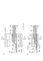
- FIG. 12 showing a plan view of the manufacturing apparatus 10 for another connection structure 1
- the manufacturing apparatus 10 capable of crimping the crimp terminals 200 at both ends in the front-rear direction X of the covered electric wire 100 may be used.
- illustration of the conveyance process part 17 is abbreviate
- the manufacturing apparatus 10 includes a cutting / removing process unit 18 having a function of cutting the covered electric wire 100 and a function of peeling off the insulating coating 102, a marking process unit 13f for the one end side of the covered electric wire 100, and an inspection process unit 14f. And the crimping process part 15f, the marking process part 13r for the other end of the covered electric wire 100, the inspection process part 14r, the crimping process part 15r, and the defective product removal process part 16r for cutting the defective crimp terminal 200. It is composed.
- the marking process unit 13f, the inspection process unit 14f, the crimping process unit 15f, the marking process unit 13r, the inspection process unit 14r, the crimping process unit 15r, and the defective product removal process unit 16r have the same configuration as that of the above-described embodiment. Therefore, detailed description is omitted.
- Such a manufacturing apparatus 10 peels off the insulation coating 102 of the covered electric wire 100 conveyed in the conveyance direction C11 by the cutting and removing step unit 18, and then, similarly to the above-described embodiment, the conveyance direction C12, the conveyance direction C13,
- the crimp terminal 200 is crimped and connected to one end in the front-rear direction X of the covered wire 100 by the marking process unit 13f, the inspection process unit 14f, and the crimping process unit 15f while transporting the coated wire 100 in the order of the transport direction C14.
- the manufacturing apparatus 10 moves the covered electric wire 100 having the crimp terminal 200 crimped and connected to one end thereof in the transport direction C15 and transports it to the inspection process unit 14f, and changes the crimp state of the crimp terminal 200 in the inspection process unit 14f.
- the covered electric wire 100 is moved in the conveyance direction C ⁇ b> 16 and conveyed to the cutting and removing process unit 18.
- the manufacturing apparatus 10 conveys the covered electric wire 100 by a predetermined length in the front-rear direction X, and then the crimping terminal 200 is crimped by the cutting / removing process unit 18. The other end side of the coated wire 100 that is not present is cut.
- the manufacturing apparatus 10 is carrying out the marking process part 13r, the test
- the connection structure 1 is configured in which the crimp terminal 200 is crimped and connected to the other end of the covered electric wire 100 by the portion 15r, and the crimp terminal 200 is crimped and connected to both ends in the front-rear direction X.
- the manufacturing apparatus 10 moves the connection structure 1 to the conveyance direction C21, after moving the connection structure 1 to the conveyance direction C22, after test
- the manufacturing apparatus 10 that crimps and connects the crimp terminal 200 to both ends of the covered electric wire 100 can achieve the same effects as those of the above-described embodiment.
- FIG. 13 which shows a plan view of the manufacturing apparatus 10 of another connection structure 1
- the carrier cutting process for separating the crimp terminal 200 from the terminal connection band 300 is performed by the independent carrier cutting process unit 15 a.
- the manufacturing apparatus 10 may be used.
- the manufacturing apparatus 10 includes a tip detection process unit 11, a coating strip process unit 12, a marking process unit 13, an inspection process unit 14, a crimping process unit 15b, and a defective product removal process unit 16.
- a carrier cut process part 15a juxtaposed with respect to the arrangement of the crimping process part 15b from the tip detection process part 11.
- the manufacturing apparatus 10 includes a transfer process unit 17 as in the above-described embodiment.
- the leading edge detection process unit 11, the coating strip process unit 12, the marking process unit 13, the inspection process unit 14, the defective product removal process unit 16, and the transfer process unit 17 are the same as those in the above-described embodiment. Because of the configuration, detailed description thereof is omitted.
- the carrier cut process part 15a has a function which isolate
- the crimping process section 15b has a function of inserting the covered electric wire 100 with the aluminum core wire 101 exposed to the crimp terminal 200 conveyed by the predetermined conveying means from the carrier cutting process section 15a, and the crimping section 230 and the covered electric wire 100. And a function of crimping.
- Such a manufacturing apparatus 10 can perform in parallel the process of exposing the aluminum core wire 101 from the covered electric wire 100 to a state where it can be crimped and the process of separating the crimp terminal 200 from the terminal connector 300. For this reason, the manufacturing method of the connection structure 1 and the manufacturing apparatus 10 of the connection structure 1 can manufacture the connection structure 1 efficiently.
Abstract
The purpose of the present invention is to provide the following: a connection-structure manufacturing method whereby a connection structure (1) in which an aluminum core (101) is firmly crimped by a closed-barrel crimp section (230), yielding stable conductivity, is manufactured efficiently; a wire harness (2); and a device (10) for manufacturing the aforementioned connection structure (1). This method and device (10) are used to manufacture connection structures (1), each of which crimps together and connects the following: a coated wire (100) provided with a wire tip section (103) where an insulating coating (102) has been stripped from the tip of the coated wire (100); and a crimp terminal (200) provided with a closed-barrel crimp section (230) that allows the wire tip section (103) to be crimp-connected. The following steps are performed, in this order: a carrier cutting step in which crimp terminals (200) are separated from a terminal attachment strip (300) comprising a plurality of crimp terminals (200) attached to a carrier (250) in a lengthwise direction; a wire insertion step in which wire tip sections (103) are inserted into the crimp sections (230) of the separated crimp terminals (200); and a crimping step in which the crimp sections (230) into which wire tip sections (103) have been inserted are crimped so as to crimp-connect same.
Description
この発明は、例えば、クローズドバレル型の圧着端子と、導体を絶縁被覆で被覆した被覆電線とを接続して構成する接続構造体の製造方法、及び接続構造体の製造装置、並びに接続構造体を用いたワイヤーハーネスに関する。
The present invention provides, for example, a connection structure manufacturing method, a connection structure manufacturing apparatus, and a connection structure, which are configured by connecting a closed barrel type crimp terminal and a covered electric wire whose conductor is covered with an insulating coating. It relates to the used wire harness.
自動車等に装備された電装品は、被覆電線を束ねたワイヤーハーネスを介して、別の電装品や電源装置と接続して電気回路を構成している。この際、ワイヤーハーネスと電装品や電源装置とは、それぞれに装着したコネクタ同士を雌雄嵌合することで接続されている。そして、コネクタの内部には、圧着端子と被覆電線とを圧着接続した接続構造体が装着されている。
この接続構造体は、被覆電線の導体を電気的に接続する圧着部を有した圧着端子に被覆電線を挿入したのち、圧着部を加締めることで、圧着端子と被覆電線とを導通可能に接続して構成している。 An electrical component equipped in an automobile or the like constitutes an electric circuit by being connected to another electrical component or a power supply device via a wire harness in which covered electric wires are bundled. At this time, the wire harness, the electrical component, and the power supply device are connected by male-female fitting of the connectors attached to each. A connection structure in which a crimp terminal and a covered electric wire are crimped and connected is mounted inside the connector.
This connection structure connects the crimping terminal and the covered wire so that they can be connected by crimping the crimping part after inserting the coated wire into the crimping terminal that has a crimping part that electrically connects the conductor of the covered wire. Configured.
ところで、昨今の電装品の多機能化、高性能化に伴って電気回路はますます複雑化しており、各圧着端子と被覆電線との圧着接続部分での確実な導電性がより求められている。このため、これまでのようなオープンバレル型の圧着端子の場合、圧着部や導体が露出しているため、過酷な使用環境下において、圧着接続部分における圧着部表面や導体表面が腐食し、導電性が低下するおそれがあった。
By the way, with the recent increase in functionality and performance of electrical components, electrical circuits are becoming more and more complex, and there is a demand for more reliable electrical conductivity at the crimped connection between each crimp terminal and covered wire. . For this reason, in the case of conventional open barrel type crimp terminals, the crimped part and conductor are exposed, so the surface of the crimped part and the conductor surface in the crimped connection are corroded in a harsh usage environment. There was a risk that the performance would decrease.
このような問題に対して、例えば、特許文献1の段落[0005]に記載されているクローズドバレル型の圧着部を備えた圧着端子を用いることにより、圧着接続部分における圧着部表面や導体表面に生じる腐食を防止することができる接続構造体を構成している。
For such a problem, for example, by using a crimp terminal provided with a closed barrel-type crimp part described in paragraph [0005] of Patent Document 1, the crimp part connection surface or conductor surface at the crimp connection part is used. The connection structure which can prevent the corrosion which arises is comprised.
クローズドバレル型の圧着端子としては、例えば、特許文献2に開示されたものがある。特許文献2の圧着端子は、特許文献2の図10~図15に開示されているように、長手方向の一方に、他端を閉じた円筒状の圧着部を有している。この円筒状の圧着部に、被覆電線の先端部分を挿入して圧着することで、特許文献2の圧着端子は、圧着端子と被覆電線の導体とを確実に導通させるとともに、圧着接続部分における圧着部表面や導体表面に生じる腐食を防止することができると考えられる。
As a closed barrel type crimp terminal, for example, there is one disclosed in Patent Document 2. As disclosed in FIG. 10 to FIG. 15 of Patent Document 2, the crimp terminal of Patent Document 2 has a cylindrical crimp part with the other end closed on one side in the longitudinal direction. By inserting and crimping the tip end portion of the covered electric wire into this cylindrical crimp portion, the crimp terminal of Patent Document 2 ensures conduction between the crimp terminal and the conductor of the covered wire, and crimping at the crimp connection portion. It is considered that corrosion occurring on the surface of the part and the surface of the conductor can be prevented.
しかし、このような形状の圧着端子は、鋳造等の方法で単独で製造しなれば得られない。つまり、帯状の銅板を打ち抜くとともに、搬送しながら順次折り曲げして圧着端子を製造するようなことができない。さらに、圧着端子を製造しながら被覆電線を接続して接続構造体を構成するようなこともできない。このため、特許文献2のようなクローズドバレル型の圧着端子では、連続して効率よく接続構造体を製造できないという問題があった。
However, a crimp terminal having such a shape cannot be obtained unless it is manufactured by a method such as casting. That is, it is not possible to manufacture a crimp terminal by punching a strip-shaped copper plate and bending it sequentially while being conveyed. Furthermore, a connection structure cannot be configured by connecting a covered electric wire while manufacturing a crimp terminal. For this reason, in the closed barrel type crimp terminal as in Patent Document 2, there is a problem that the connection structure cannot be manufactured continuously and efficiently.
本発明は、クローズドバレル型の圧着部で導体部分を確実に圧着して、安定した導電性を有する接続構造体を効率よく製造する接続構造体の製造方法、ワイヤーハーネス、及び接続構造体の製造装置を提供することを目的とする。
The present invention relates to a method for manufacturing a connection structure, a wire harness, and a manufacture of a connection structure, in which a conductor portion is securely crimped with a closed barrel-type crimp portion and a connection structure having stable conductivity is efficiently manufactured. An object is to provide an apparatus.
この発明は、導体を絶縁被覆で被覆し、先端側の前記絶縁被覆を剥がして先端側の前記導体を露出させた電線先端部を備えた被覆電線と、前記電線先端部の圧着接続を許容するクローズドバレル型の圧着部を備えた圧着端子とを、前記圧着部で前記電線先端部を圧着して接続する接続構造体の製造方法であって、帯状に形成されたキャリアに対して、該キャリアの短手方向に沿って前記圧着端子が連結されるとともに、前記キャリアの長手方向に所定間隔を隔てて複数の前記圧着端子を連結した端子連結帯から前記圧着端子を分離するキャリアカット工程と、前記被覆電線の少なくとも前記電線先端部を、前記キャリアから分離された前記圧着端子の前記圧着部に挿入する電線挿入工程と、前記電線先端部が挿入された前記圧着部を圧着して圧着接続する圧着工程とを、この順で行うこと及び同工程を行う製造装置であることを特徴とする。
The present invention permits a crimped connection between a coated electric wire provided with a wire tip portion in which a conductor is covered with an insulating coating, the insulating coating on the tip side is peeled off and the conductor on the tip side is exposed, and the wire tip portion. A connection structure manufacturing method for connecting a crimping terminal having a closed barrel-type crimping part by crimping the tip of the electric wire at the crimping part. The crimp terminal is connected along the short direction of the carrier, and a carrier cutting step of separating the crimp terminal from a terminal connection band in which a plurality of the crimp terminals are connected at a predetermined interval in the longitudinal direction of the carrier, A wire insertion step of inserting at least the wire tip of the covered wire into the crimp portion of the crimp terminal separated from the carrier, and crimping the crimp portion into which the wire tip is inserted. A crimping step of crimping connection, characterized in that it is a manufacturing apparatus for performing the and the process carried out in this order.
上記圧着端子は、断面中空形状の圧着部を有するクローズドバレル型の端子であり、一対構成した端子組における他方の端子の接続部との接続を許容する接続部を有する接続端子、あるいは圧着部のみで構成する端子であることを含む。
The crimp terminal is a closed barrel type terminal having a crimp section with a hollow cross-section, and a connection terminal having a connection section that allows connection with the connection section of the other terminal in a pair of terminal sets, or only the crimp section Including a terminal constituted by
この発明により、クローズドバレル型の圧着部で導体部分を確実に圧着して、安定した導電性を有する接続構造体を効率よく製造することができる。
詳述すると、接続構造体の製造方法、及び接続構造体の製造装置は、端子連結帯から分離した圧着端子に対して被覆電線を挿入して圧着することで、例えば、鋳造等の方法でそれぞれを単独で製造する圧着端子を用いる場合と比較して、被覆電線を挿入する圧着端子を効率よく供給できる。このため、接続構造体の製造方法、及び接続構造体の製造装置は、接続構造体を効率よく製造することができる。 According to the present invention, it is possible to efficiently manufacture a connection structure having stable conductivity by securely crimping a conductor portion with a closed barrel crimping portion.
More specifically, the connection structure manufacturing method and the connection structure manufacturing apparatus insert a covered electric wire into a crimp terminal separated from a terminal connection band and crimp it, for example, by a method such as casting. Compared with the case where the crimp terminal which manufactures this alone is used, the crimp terminal into which the covered electric wire is inserted can be supplied efficiently. For this reason, the manufacturing method of a connection structure and the manufacturing apparatus of a connection structure can manufacture a connection structure efficiently.
また、帯状に形成されたキャリアに対して、オープンバレル型である圧着部を有する圧着端子が、キャリアの長手方向に所定間隔を隔てて複数配置された端子連結帯の場合、キャリアに対する圧着端子の連結方向と、圧着部への被覆電線の挿入方向とが異なる。このため、例えば、端子連結帯からの圧着端子を分離する際の分離手段が、圧着部への被覆電線の挿入に支障することなく、圧着部への被覆電線の挿入と、端子連結帯からの圧着端子の分離とを同時に行うことができる。
In addition, in the case of a terminal connection band in which a plurality of crimp terminals having a crimp portion that is an open barrel type with respect to a carrier formed in a band shape are arranged at predetermined intervals in the longitudinal direction of the carrier, The connection direction is different from the insertion direction of the covered electric wire to the crimping part. For this reason, for example, the separating means when separating the crimp terminal from the terminal connection band does not interfere with the insertion of the covered electric wire into the crimp part, and the insertion of the covered electric wire into the crimp part and the Separation of the crimp terminal can be performed simultaneously.
これに対して、クローズドバレル型である圧着部がキャリアに連結された端子連結帯では、キャリアに対する圧着端子の連結方向と、圧着部への被覆電線の挿入方向とが同方向となるため、端子連結帯からの圧着端子を分離する際の分離手段が、クローズドバレル型の圧着部への被覆電線の挿入に支障することとなる。加えて、被覆電線を挿入したクローズドバレル型の圧着部を、分離手段によって被覆電線を損傷することなく端子連結帯から分離することも困難である。
On the other hand, in the terminal connection band in which the crimping part that is a closed barrel type is connected to the carrier, the connecting direction of the crimping terminal with respect to the carrier and the insertion direction of the covered electric wire into the crimping part are the same direction. Separating means for separating the crimp terminal from the connection band hinders the insertion of the covered electric wire into the closed barrel type crimp part. In addition, it is difficult to separate the closed barrel-type crimping portion into which the covered electric wire has been inserted from the terminal connection band without damaging the covered electric wire by the separating means.
しかしながら、接続構造体の製造方法、及び接続構造体の製造装置は、端子連結帯から分離した圧着端子に対して被覆電線を挿入して圧着するため、分離手段が圧着部への被覆電線の挿入に支障することなく、接続構造体を効率よく製造することができる。
However, since the manufacturing method of the connection structure and the manufacturing apparatus of the connection structure insert the covered electric wire into the crimp terminal separated from the terminal coupling band and perform the crimping, the separating unit inserts the covered electric wire into the crimp portion. The connection structure can be efficiently manufactured without hindering the operation.
従って、接続構造体の製造方法、及び接続構造体の製造装置は、クローズドバレル型の圧着部で導体部分を確実に圧着して、安定した導電性を有する接続構造体を効率よく製造することができる。
Therefore, the manufacturing method of the connection structure and the manufacturing apparatus of the connection structure can efficiently manufacture the connection structure having stable conductivity by securely crimping the conductor portion with the closed barrel type crimping portion. it can.
この発明の態様として、所定位置に配置された前記被覆電線の先端側の前記絶縁被覆を剥がして前記電線先端部を構成する被覆ストリップ工程を、前記キャリアカット工程より先に行うことができる。
As an aspect of the present invention, the covering strip step of peeling off the insulating coating on the tip end side of the covered electric wire arranged at a predetermined position to constitute the electric wire tip portion can be performed prior to the carrier cutting step.
この発明により、接続構造体をさらに、効率よく製造することができる。
詳述すると、接続構造体の製造方法、及び接続構造体の製造装置は、所定位置に配置された被覆電線の先端側の絶縁被覆を剥がして電線先端部を構成する被覆ストリップ工程を、キャリアカット工程より先に行う、つまり一旦被覆電線を所定配置に配置すると、導体が露出する電線先端部を構成するとともに、その後の一連の工程を行うことができる。 According to the present invention, the connection structure can be manufactured more efficiently.
More specifically, the method for manufacturing a connection structure and the apparatus for manufacturing a connection structure include a carrier-cutting process in which a coating strip process is performed in which the insulating coating on the tip side of the covered wire arranged at a predetermined position is peeled off to form the wire tip. Performing prior to the process, that is, once the covered electric wire is arranged in a predetermined arrangement, it is possible to configure the wire tip portion where the conductor is exposed and to perform a series of subsequent steps.
これにより、接続構造体の製造方法、及び接続構造体の製造装置は、例えば、ストリップする被覆電線を一旦、所定位置にセットするだけで、その後の工程を連続して行うことができる。このため、接続構造体の製造方法、及び接続構造体の製造装置は、接続構造体をさらに、効率よく製造することができる。
Thereby, the manufacturing method of the connection structure and the manufacturing apparatus of the connection structure can perform the subsequent steps continuously, for example, by once setting the covered electric wire to be stripped at a predetermined position. For this reason, the manufacturing method of a connection structure and the manufacturing apparatus of a connection structure can manufacture a connection structure further efficiently.
またこの発明の態様として、前記絶縁被覆における前記圧着部への前記電線先端部の挿入長さに応じた所定位置に目印をマーキングするマーキング工程を、前記被覆ストリップ工程と前記キャリアカット工程との間に行い、前記圧着工程後に、前記目印を用いて、前記圧着部への前記電線先端部の圧着状態を検査する検査工程を行うことができる。
Further, as an aspect of the present invention, a marking step of marking a mark at a predetermined position according to the insertion length of the wire tip portion into the crimp portion in the insulating coating is performed between the coating strip step and the carrier cutting step. After the crimping step, an inspection step of inspecting the crimping state of the wire tip to the crimping portion can be performed using the mark.
上記圧着状態を検査するとは、例えば、クローズドバレル型の圧着部に対する電線先端部の挿入長さ、つまり所定位置まで電線先端部を挿入できているか否かの検査、圧着部に挿入できずに折り返されて圧着部から出ている素線の有無の検査、あるいは圧着部に対して被覆電線が曲がって圧着されているか否かの検査など、導電性や耐久性等の接続構造体の品質に係る事項に関する検査を行うことを示している。
また、上記検査は、目視による検査や、例えば、画像処理やセンサ等による検出に基づく機械的な検査を含むものとする。 Inspecting the above crimping state means, for example, the insertion length of the wire tip with respect to the closed barrel type crimping portion, that is, whether or not the wire tip can be inserted to a predetermined position, folded without being inserted into the crimping portion. This is related to the quality of the connection structure such as conductivity and durability, such as inspection of the presence or absence of wires coming out from the crimping part, or inspection of whether or not the coated electric wire is bent and crimped to the crimping part. Indicates that an inspection will be conducted on the matter.
The inspection includes visual inspection and, for example, mechanical inspection based on detection by image processing or a sensor.
この発明により、導電性や耐久性等などを確実に得ることができる高品質な接続構造体を製造することができる。
詳しくは、例えば、被覆ストリップ工程によって絶縁被覆を剥がす際、絶縁被覆の先端と導体の先端とに位置ズレが生じることがある。このため、被覆ストリップ工程前にマーキング工程を行う場合、絶縁被覆の先端からの長さに基づいて所定位置を決定することで、被覆ストリップ工程後の目印の位置が所望する位置とは異なる位置となり、圧着部に対する電線先端部の挿入長さが不足して、安定した導電性を確保した接続構造体を製造できないおそれがある。 According to the present invention, it is possible to manufacture a high-quality connection structure that can reliably obtain conductivity, durability, and the like.
Specifically, for example, when the insulating coating is peeled off by the coating strip process, a positional deviation may occur between the tip of the insulating coating and the tip of the conductor. Therefore, when the marking process is performed before the covering strip process, the position of the mark after the covering strip process is different from the desired position by determining the predetermined position based on the length from the tip of the insulating coating. The insertion length of the wire tip portion with respect to the crimping portion is insufficient, and there is a possibility that a connection structure that ensures stable conductivity cannot be manufactured.
これに対して、被覆ストリップ工程後にマーキング工程を行うことで、接続構造体の製造方法、及び接続構造体の製造装置は、電線先端部の先端からの長さに基づいて所定位置を決定することができるため、所望する位置に正確に目印をマーキングすることができる。
On the other hand, by performing the marking process after the covering strip process, the connection structure manufacturing method and the connection structure manufacturing apparatus determine a predetermined position based on the length from the tip of the wire tip. Therefore, the mark can be accurately marked at a desired position.
そして、圧着工程後に、マーキング工程でマーキングされた目印を用いて、圧着部への電線先端部の圧着状態を検査するため、例えば、クローズドバレル型の圧着部に対する所定位置まで電線先端部を挿入できていない、あるいは、圧着部への電線先端部の挿入時に、導体を構成する素線の一部が引っ掛かって折り返された状態で圧着されているなどの導電性が低下する要因となる不具合を、接続構造体の製造方法、及び接続構造体の製造装置は、絶縁被覆にマーキングされた目印を用いることで容易に判別することができる。
Then, after the crimping process, using the mark marked in the marking process, the crimping state of the wire tip to the crimping part is inspected. For example, the wire tip can be inserted to a predetermined position with respect to the closed barrel crimping part. Or, when inserting the tip of the electric wire into the crimping part, a problem that causes a decrease in conductivity, such as being crimped in a state where a part of the wire constituting the conductor is caught and folded, The manufacturing method of the connection structure and the manufacturing apparatus of the connection structure can be easily determined by using the mark marked on the insulating coating.
さらに、圧着部に対して被覆電線が曲がって圧着されているなどの耐久性が低下する要因となる不具合を、接続構造体の製造方法、及び接続構造体の製造装置は、絶縁被覆にマーキングされた目印を用いることで容易に判別することができる。
したがって、接続構造体の製造方法、及び接続構造体の製造装置は、導電性や耐久性等などが確実に得ることができる高品質な接続構造体を製造することができる。 Furthermore, the manufacturing method of the connection structure and the manufacturing apparatus of the connection structure are marked on the insulating coating for defects that cause a decrease in durability, such as the coated wire being bent and crimped to the crimping portion. It can be easily distinguished by using a mark.
Therefore, the manufacturing method of the connection structure and the manufacturing apparatus of the connection structure can manufacture a high-quality connection structure that can reliably obtain conductivity, durability, and the like.
またこの発明の態様として、前記導体を、アルミ系材料で構成するとともに、少なくとも前記圧着部を、銅系材料で構成することができる。
上記銅系材料は、銅、銅合金等で構成することができ、また、アルミ系材料で構成する導体は、アルミニウム製あるいはアルミニウム合金製の芯線や素線を撚った撚線で構成することができる。 As an aspect of the present invention, the conductor can be made of an aluminum-based material, and at least the pressure-bonding portion can be made of a copper-based material.
The copper-based material can be composed of copper, copper alloy, etc., and the conductor composed of the aluminum-based material is composed of aluminum or aluminum alloy core wire or stranded wire twisted. Can do.
この発明により、銅線による導体を有する被覆電線に比べて軽量化を図るとともに、安定した導電性を有する接続構造体を効率よく製造することができる。
ところで、被覆電線の導体に従来用いられていた銅系材料をアルミニウムあるいはアルミニウム合金などのアルミ系材料に置き換え、そのアルミ系材料製の導体を圧着端子に圧着した場合においては、端子材料の錫めっき、金めっき、銅合金等の貴な金属との接触により、卑な金属であるアルミ系材料が腐食される現象、すなわち電食が問題となることがある。 According to the present invention, it is possible to reduce the weight as compared to a covered electric wire having a conductor made of copper wire, and to efficiently manufacture a connection structure having stable conductivity.
By the way, if the copper-based material conventionally used for the conductor of the covered wire is replaced with an aluminum-based material such as aluminum or aluminum alloy, and the conductor made of the aluminum-based material is crimped to the crimp terminal, the terminal material is tin-plated There is a case where a base metal such as an aluminum material is corroded by contact with a noble metal such as gold plating or copper alloy, that is, electrolytic corrosion may be a problem.
なお、電食とは、貴な金属と卑な金属とが接触している部位に水分が付着すると、腐食電流が生じ、卑な金属が腐食、溶解、消失等する現象である。この現象により、圧着端子の圧着部に圧着されたアルミ系材料製の導体が腐食、溶解、消失し、やがては電気抵抗が上昇する。その結果、十分な導電機能を果たせなくなるという問題があった。
Incidentally, electrolytic corrosion is a phenomenon in which when a moisture adheres to a site where a noble metal and a base metal are in contact, a corrosion current is generated, and the base metal is corroded, dissolved, or lost. Due to this phenomenon, the conductor made of an aluminum-based material that is crimped to the crimping portion of the crimping terminal is corroded, dissolved, or lost, and eventually the electrical resistance increases. As a result, there is a problem that a sufficient conductive function cannot be achieved.
これに対して、クローズドバレル型の圧着部における開口を、別体のシール部材によってシールする、あるいは加締めることによって封止することで、接続構造体の製造方法は、圧着部の内部への水分に侵入に対する止水性を容易に確保することができる。このため、接続構造体の製造方法は、銅系材料による導体を有する被覆電線に比べて軽量化を図りながら、いわゆる電食を防止する接続構造体を製造することができる。
従って、接続構造体の製造方法は、被覆電線の導体を構成する金属種によらず、軽量化を図って、安定した導電性を確保できる接続構造体を製造することができる。 On the other hand, by sealing the opening in the closed barrel-type crimping portion with a separate sealing member or by caulking, the manufacturing method of the connection structure allows moisture to the inside of the crimping portion. It is possible to easily ensure water-stopping against intrusion. For this reason, the manufacturing method of a connection structure can manufacture the connection structure which prevents what is called electrolytic corrosion, achieving weight reduction compared with the covered electric wire which has the conductor by a copper-type material.
Therefore, the connection structure manufacturing method can manufacture a connection structure capable of ensuring a stable conductivity by reducing the weight regardless of the metal species constituting the conductor of the covered electric wire.
またこの発明は、上述した接続構造体の製造方法で製造した接続構造体を複数本束ねるとともに、前記接続構造体における圧着端子を、コネクタハウジング内に装着したワイヤーハーネスであることを特徴とする。
この発明により、安定した導電性を確保するとともに、効率よく製造された接続構造体によって、良好な導電性を確保したワイヤーハーネスを構成することができる。 In addition, the present invention is a wire harness in which a plurality of connection structures manufactured by the above-described connection structure manufacturing method are bundled, and crimp terminals in the connection structure are mounted in a connector housing.
By this invention, while ensuring the stable electroconductivity, the wire harness which ensured favorable electroconductivity can be comprised with the connection structure manufactured efficiently.
本発明により、クローズドバレル型の圧着部で導体部分を確実に圧着して、安定した導電性を有する接続構造体を効率よく製造する接続構造体の製造方法、ワイヤーハーネス、及び接続構造体の製造装置を提供することができる。
INDUSTRIAL APPLICABILITY According to the present invention, a method for manufacturing a connection structure, a wire harness, and a manufacture of a connection structure that efficiently manufactures a connection structure having stable conductivity by securely crimping a conductor portion with a closed barrel-type crimp portion An apparatus can be provided.
この発明の一実施形態を以下図面と共に説明する。
まず、本実施形態における接続構造体1について、図1から図4を用いて詳しく説明する。
なお、図1は接続構造体1を説明する説明図を示し、図2は圧着部230における溶接について説明する説明図を示し、図3は端子連結帯300、及び被覆電線100における上方からの平面図を示し、図4は図3中のA-A矢視断面図を示している。さらに、図1(a)は接続構造体1の前方上方視からの外観斜視図を示し、図1(b)は接続構造体1を構成する被覆電線100及び圧着端子200の前方上方視からの外観斜視図を示している。 An embodiment of the present invention will be described below with reference to the drawings.
First, the connection structure 1 in this embodiment will be described in detail with reference to FIGS.
FIG. 1 is an explanatory view for explaining the connection structure 1, FIG. 2 is an explanatory view for explaining welding in the crimpingportion 230, and FIG. 3 is a plan view from above of the terminal connection band 300 and the covered electric wire 100. FIG. 4 is a cross-sectional view taken along line AA in FIG. Further, FIG. 1A shows an external perspective view of the connection structure 1 from the front upper view, and FIG. 1B shows the covered electric wire 100 and the crimp terminal 200 constituting the connection structure 1 from the front upper view. The external appearance perspective view is shown.
まず、本実施形態における接続構造体1について、図1から図4を用いて詳しく説明する。
なお、図1は接続構造体1を説明する説明図を示し、図2は圧着部230における溶接について説明する説明図を示し、図3は端子連結帯300、及び被覆電線100における上方からの平面図を示し、図4は図3中のA-A矢視断面図を示している。さらに、図1(a)は接続構造体1の前方上方視からの外観斜視図を示し、図1(b)は接続構造体1を構成する被覆電線100及び圧着端子200の前方上方視からの外観斜視図を示している。 An embodiment of the present invention will be described below with reference to the drawings.
First, the connection structure 1 in this embodiment will be described in detail with reference to FIGS.
FIG. 1 is an explanatory view for explaining the connection structure 1, FIG. 2 is an explanatory view for explaining welding in the crimping
また、図1中において、矢印Xは前後方向を示し(以下「前後方向X」とする)、矢印Yは幅方向を示している(以下、「幅方向Y」とする)。さらに、前後方向Xにおいて、後述するボックス部210側(図1中の左側)を前方とし、ボックス部210に対して後述する被覆電線100側(図1中の右側)を後方とする。加えて、図1中の上側を上方とし、図1中の下側を下方とする。
In FIG. 1, an arrow X indicates the front-rear direction (hereinafter referred to as “front-rear direction X”), and an arrow Y indicates the width direction (hereinafter referred to as “width direction Y”). Furthermore, in the front-rear direction X, the box part 210 side (left side in FIG. 1) described later is defined as the front, and the covered electric wire 100 side (right side in FIG. 1) described later with respect to the box part 210 is defined as the rear. In addition, the upper side in FIG. 1 is the upper side, and the lower side in FIG. 1 is the lower side.
接続構造体1は、図1(a)に示すように、被覆電線100と圧着端子200とを圧着接続して構成している。
被覆電線100は、図1(b)に示すように、複数のアルミニウム素線101aを束ねたアルミニウム芯線101を、絶縁樹脂で構成する絶縁被覆102で被覆して構成している。例えば、アルミニウム芯線101は、断面が0.75mm2となるように、アルミニウム合金線を撚って構成している。 As illustrated in FIG. 1A, the connection structure 1 is configured by crimping and connecting a coveredelectric wire 100 and a crimp terminal 200.
As shown in FIG. 1B, the coveredelectric wire 100 is configured by covering an aluminum core wire 101 in which a plurality of aluminum wires 101a are bundled with an insulating coating 102 made of an insulating resin. For example, the aluminum core wire 101 is formed by twisting an aluminum alloy wire so that the cross section is 0.75 mm 2 .
被覆電線100は、図1(b)に示すように、複数のアルミニウム素線101aを束ねたアルミニウム芯線101を、絶縁樹脂で構成する絶縁被覆102で被覆して構成している。例えば、アルミニウム芯線101は、断面が0.75mm2となるように、アルミニウム合金線を撚って構成している。 As illustrated in FIG. 1A, the connection structure 1 is configured by crimping and connecting a covered
As shown in FIG. 1B, the covered
さらに、被覆電線100は、先端から前後方向Xに所定の長さだけ絶縁被覆102を剥がしてアルミニウム芯線101を露出させることで電線先端部103を構成している。加えて、被覆電線100における絶縁被覆102の上方側表面には、電線先端部103の先端から所定の長さの位置において、被覆電線100の周方向に略線状の目印104を設けている。なお、目印104については、後ほど詳しく説明する。
Furthermore, the covered electric wire 100 constitutes the electric wire tip portion 103 by peeling off the insulating coating 102 by a predetermined length in the front-rear direction X from the tip to expose the aluminum core wire 101. In addition, a substantially linear mark 104 is provided in the circumferential direction of the covered electric wire 100 at a position of a predetermined length from the tip of the electric wire tip 103 on the upper surface of the insulating coating 102 in the covered electric wire 100. The mark 104 will be described in detail later.
圧着端子200は、図1(a)及び図1(b)に示すように、メス型端子であり、前後方向Xの前方から後方に向かって、図示省略するオス型端子のオスタブの挿入を許容するボックス部210と、ボックス部210の後方で、所定の長さのトランジション部220を介して配置された圧着部230とを一体に構成している。
As shown in FIGS. 1A and 1B, the crimp terminal 200 is a female terminal, and allows insertion of male tabs of male terminals (not shown) from the front to the rear in the front-rear direction X. The box portion 210 and the crimping portion 230 disposed behind the box portion 210 via a transition portion 220 having a predetermined length are integrally configured.
この圧着端子200は、表面が錫メッキ(Snメッキ)された黄銅等の銅合金条(図示せず)を、平面展開した端子形状に打ち抜いた後、中空四角柱体のボックス部210と後方視略O型の圧着部230とからなる立体的な端子形状に曲げ加工するとともに、圧着部230を溶接して構成したクローズドバレル型の端子である。
The crimp terminal 200 is formed by punching a copper alloy strip (not shown) such as brass whose surface is tin-plated (Sn-plated) into a planarly expanded terminal shape, and then rearwardly viewing the box portion 210 of the hollow rectangular column body. The closed barrel type terminal is formed by bending into a three-dimensional terminal shape composed of a substantially O-shaped crimping portion 230 and welding the crimping portion 230.
ボックス部210は、図1及び図2に示すように、底面部211の前後方向Xと直交する幅方向Yの両側部に連設された側面部212の一方を、他方の端部に重なり合うように折り曲げて、前後方向Xの前方側から見て略矩形の倒位の中空四角柱体で構成されている。
As shown in FIG. 1 and FIG. 2, the box part 210 overlaps one end of the side part 212 connected to both side parts in the width direction Y orthogonal to the front-rear direction X of the bottom part 211 on the other end part. And is formed of a substantially rectangular inverted hollow quadrangular prism body as viewed from the front side in the front-rear direction X.
さらに、ボックス部210の内部には、底面部211における前後方向Xの前方側を延設して、前後方向Xの後方に向かって折り曲げて形成され、挿入されるオス型端子の挿入タブ(図示省略)に接触する弾性接触片213を備えている(図4参照)。
Further, an insertion tab of a male terminal (illustrated) is formed in the box portion 210 by extending the front side in the front-rear direction X of the bottom surface portion 211 and bending it toward the rear in the front-rear direction X. The elastic contact piece 213 that contacts (not shown) is provided (see FIG. 4).
圧着部230は、図1、図2及び図4に示すように、絶縁被覆102を圧着する被覆圧着部231と、電線先端部103を圧着する導体圧着部232と、導体圧着部232より前方端部を略平板状に押しつぶすように変形させた封止部233とを一体にして構成している。
As shown in FIGS. 1, 2, and 4, the crimping portion 230 includes a coating crimping portion 231 that crimps the insulating coating 102, a conductor crimping portion 232 that crimps the wire tip portion 103, and a front end from the conductor crimping portion 232. The sealing part 233 which deform | transformed so that a part may be crushed in substantially flat form is comprised integrally.
この圧着部230は、図2に示すように、端子形状に打ち抜いた銅合金条を被覆電線100の外径と略同等、もしくは被覆電線100の外径より僅かに大きい内径で被覆電線100の外周を包囲するように丸めるとともに、丸めた端部230a,230b同士を突き合わせて前後方向Xの溶接個所W1に沿って溶接して後方視略O型に形成している。換言すると、圧着部230は、幅方向Yにおける断面形状を閉断面形状に形成している。
As shown in FIG. 2, the crimping portion 230 has a copper alloy strip punched into a terminal shape that is substantially the same as the outer diameter of the covered electric wire 100 or has an inner diameter slightly larger than the outer diameter of the covered electric wire 100. The rounded end portions 230a and 230b are brought into contact with each other and welded along the welding point W1 in the front-rear direction X to form a substantially O-shape in rear view. In other words, the crimping part 230 forms the cross-sectional shape in the width direction Y into a closed cross-sectional shape.
さらに、圧着部230の封止部233は、図2及び図4に示すように、圧着部230の前後方向Xの前端を閉塞するように幅方向Yの溶接個所W2に沿って溶接して封止している。
つまり、圧着部230は、前後方向Xの前端、及び端部230a,230b同士を溶着して閉塞して、前後方向Xの後方に開口を有する略筒状に形成している。 Further, as shown in FIGS. 2 and 4, the sealingportion 233 of the crimping portion 230 is welded and sealed along the welding portion W2 in the width direction Y so as to close the front end of the crimping portion 230 in the front-rear direction X. It has stopped.
That is, the crimpingportion 230 is formed in a substantially cylindrical shape having a front end in the front-rear direction X and end portions 230 a and 230 b being welded and closed, and having an opening at the rear in the front-rear direction X.
つまり、圧着部230は、前後方向Xの前端、及び端部230a,230b同士を溶着して閉塞して、前後方向Xの後方に開口を有する略筒状に形成している。 Further, as shown in FIGS. 2 and 4, the sealing
That is, the crimping
このような圧着端子200が、圧着端子200の幅方向Yを長手方向とする略帯状のキャリア250に複数連結して端子連結帯300を構成している。より詳しくは、端子連結帯300は、図3及び図4に示すように、平面視において、圧着端子200の長手方向である前後方向Xに対して、キャリア250の長手方向と直交する短手方向が略一致するように、圧着端子200における圧着部230の後方下端がキャリア250に連結されている。そして、端子連結帯300は、キャリア250の長手方向に所定の間隔を隔てて複数の圧着端子200を連結している。
A plurality of such crimp terminals 200 are connected to a substantially band-shaped carrier 250 whose longitudinal direction is the width direction Y of the crimp terminal 200 to constitute a terminal connection band 300. More specifically, as shown in FIGS. 3 and 4, the terminal connection band 300 is a short direction perpendicular to the longitudinal direction of the carrier 250 with respect to the longitudinal direction X that is the longitudinal direction of the crimp terminal 200 in plan view. Are connected to the carrier 250 at the rear lower end of the crimping portion 230 in the crimp terminal 200. The terminal connection band 300 connects the plurality of crimp terminals 200 with a predetermined interval in the longitudinal direction of the carrier 250.
この端子連結帯300は、略平板状の銅合金条を打ち抜き加工して略帯状のキャリア250と平面展開した端子形状部分とが連結した形状に形成された銅合金条における端子形状部分を立体的な端子形状に曲げ加工することで、圧着端子200を複数連結した状態を構成している。
This terminal connection band 300 is formed by three-dimensionally forming a terminal shape portion in a copper alloy strip formed by punching a substantially flat copper alloy strip and connecting the substantially strip-shaped carrier 250 and the terminal shape portion developed in a plane. By bending into a simple terminal shape, a state in which a plurality of crimp terminals 200 are connected is configured.
このような端子連結帯300における圧着端子200に被覆電線100を圧着接続して接続構造体1を製造する製造装置10、及び接続構造体1を製造する製造工程について、図5から図9を用いて詳しく説明する。
A manufacturing apparatus 10 for manufacturing the connection structure 1 by crimping and connecting the covered electric wire 100 to the crimp terminal 200 in the terminal connection band 300 and a manufacturing process for manufacturing the connection structure 1 will be described with reference to FIGS. Will be described in detail.
なお、図5は製造装置10における上方からの平面図を示し、図6は製造工程の動作のフローチャートを示し、図7は圧着工程部15におけるキャリアカット工程を説明する説明図を示し、図8は圧着工程部15における電線挿入工程を説明する説明図を示し、図9は圧着工程部15における圧着工程を説明する説明図を示している。
また、図6では詳細な図示を省略しているが、製造工程の動作において、後述する搬送工程部17によって被覆電線100及び接続構造体1を次工程に搬送する搬送工程が、各工程間において行われるものとする。 5 shows a plan view from above in themanufacturing apparatus 10, FIG. 6 shows a flowchart of the operation of the manufacturing process, FIG. 7 shows an explanatory diagram for explaining the carrier cutting process in the crimping process section 15, and FIG. FIG. 9 shows an explanatory diagram for explaining the electric wire insertion process in the crimping process section 15, and FIG. 9 shows an explanatory diagram for explaining the crimping process in the crimping process section 15.
In addition, although detailed illustration is omitted in FIG. 6, in the operation of the manufacturing process, a transport process of transporting the coveredwire 100 and the connection structure 1 to the next process by the transport process unit 17 described later is performed between the processes. Shall be done.
また、図6では詳細な図示を省略しているが、製造工程の動作において、後述する搬送工程部17によって被覆電線100及び接続構造体1を次工程に搬送する搬送工程が、各工程間において行われるものとする。 5 shows a plan view from above in the
In addition, although detailed illustration is omitted in FIG. 6, in the operation of the manufacturing process, a transport process of transporting the covered
また、図7(a)はキャリアカット工程における第1段階の断面図を示し、図7(b)はキャリアカット工程における最終段階の断面図を示し、図8(a)は電線挿入工程における断面図を示し、図8(b)は電線挿入工程における側面図を示し、図9(a)は圧着工程における第1段階の断面図を示し、図9(b)は圧着工程における最終段階の断面図を示している。さらに、図7から図9において、要部を明確にするため、圧着端子200におけるボックス部210の図示を省略している。
7A shows a cross-sectional view of the first stage in the carrier cutting process, FIG. 7B shows a cross-sectional view of the final stage in the carrier cutting process, and FIG. 8A shows a cross-section in the wire insertion process. 8 (b) shows a side view in the wire insertion process, FIG. 9 (a) shows a sectional view in the first stage in the crimping process, and FIG. 9 (b) shows a sectional view in the final stage in the crimping process. The figure is shown. Furthermore, in FIG. 7 to FIG. 9, the box part 210 in the crimp terminal 200 is not shown in order to clarify the main part.
まず、接続構造体1を製造する製造装置10は、図5に示すように、先端検出工程部11と、被覆ストリップ工程部12と、マーキング工程部13と、検査工程部14と、圧着工程部15と、不良品除去工程部16とをこの順番で配置して構成している。なお、製造装置10には、先端検出工程部11から不良品除去工程部16までの間を移動可能に構成し、被覆電線100及び接続構造体1を搬送する搬送手段である搬送工程部17を備えている。
First, as shown in FIG. 5, the manufacturing apparatus 10 that manufactures the connection structure 1 includes a tip detection process unit 11, a covering strip process unit 12, a marking process unit 13, an inspection process unit 14, and a crimping process unit. 15 and the defective product removal process section 16 are arranged in this order. The manufacturing apparatus 10 includes a transfer process unit 17 that is configured to be movable between the tip detection process unit 11 and the defective product removal process unit 16 and that is a transfer unit that transfers the covered electric wire 100 and the connection structure 1. I have.
先端検出工程部11は、接触センサなどで構成し、搬送された被覆電線100の先端の位置を検出する機能を有している。
被覆ストリップ工程部12は、例えば、上下二分割された断面略V字状の被覆除去刃型(図示省略)や被覆除去刃型を所定の方向に移動させる移動機構(図示省略)などで構成し、搬送された被覆電線100の先端から所定の長さの絶縁被覆102を取り除いてアルミニウム芯線101を露出させる機能を有している。 The tip detection process part 11 is comprised with a contact sensor etc., and has the function to detect the position of the front-end | tip of the conveyed coveredelectric wire 100. FIG.
The coveringstrip process part 12 is comprised by the moving mechanism (illustration omitted) etc. which move the covering removal blade type | mold (illustration omitted) of the substantially V-shaped cross section divided into the upper and lower parts, the covering removal blade type | mold in a predetermined direction, for example. The insulation coating 102 having a predetermined length is removed from the tip of the conveyed covered electric wire 100 to expose the aluminum core wire 101.
被覆ストリップ工程部12は、例えば、上下二分割された断面略V字状の被覆除去刃型(図示省略)や被覆除去刃型を所定の方向に移動させる移動機構(図示省略)などで構成し、搬送された被覆電線100の先端から所定の長さの絶縁被覆102を取り除いてアルミニウム芯線101を露出させる機能を有している。 The tip detection process part 11 is comprised with a contact sensor etc., and has the function to detect the position of the front-end | tip of the conveyed covered
The covering
マーキング工程部13は、塗料タンク(図示省略)や塗料を噴出する噴出口(図示省略)などで構成し、被覆電線100における所定の位置に対して塗料を噴出して目印をマーキングする機能を有している。
検査工程部14は、イメージセンサー(図示省略)などで構成し、搬送された被覆電線100における先端近傍を上方から撮像して画像データを取得するとともに、撮像した画像データに基づいて被覆電線100における先端近傍の状態を検出する機能を有している。 The markingprocess unit 13 includes a paint tank (not shown), a jet outlet (not shown) for jetting paint, and the like, and has a function of jetting paint to a predetermined position on the covered electric wire 100 to mark a mark. is doing.
Theinspection process unit 14 is configured by an image sensor (not shown) and the like, captures the vicinity of the tip of the conveyed covered electric wire 100 from above, obtains image data, and in the covered electric wire 100 based on the imaged image data. It has a function of detecting the state near the tip.
検査工程部14は、イメージセンサー(図示省略)などで構成し、搬送された被覆電線100における先端近傍を上方から撮像して画像データを取得するとともに、撮像した画像データに基づいて被覆電線100における先端近傍の状態を検出する機能を有している。 The marking
The
圧着工程部15は、端子連結帯300を搬送する搬送機構(図示省略)、ボックス部210を保持する保持機構(図示省略)、圧着部230を圧着する圧着刃型41(図9参照)、端子連結帯300から圧着端子200を分離する分離刃型40(図7参照)、及び圧着刃型41や分離刃型40を所定の方向に移動させる移動機構(図示省略)などで構成している。この圧着工程部15は、端子連結帯300を搬送する機能と、搬送された端子連結帯300から圧着端子200を分離する機能と、圧着部230に挿入された被覆電線100を圧着する機能とを有している。
The crimping process section 15 includes a transport mechanism (not shown) for transporting the terminal connection band 300, a holding mechanism (not shown) for holding the box section 210, a crimping blade mold 41 (see FIG. 9) for crimping the crimping section 230, and a terminal. A separation blade mold 40 (see FIG. 7) that separates the crimp terminal 200 from the connection band 300, a moving mechanism (not shown) that moves the crimp blade 41 and the separation blade mold 40 in a predetermined direction, and the like. The crimping process unit 15 has a function of transporting the terminal connection band 300, a function of separating the crimp terminal 200 from the transported terminal connection band 300, and a function of crimping the covered electric wire 100 inserted into the crimping unit 230. Have.
なお、圧着刃型41は、図9に示すように、上下二分割された上刃型41a及び下刃型41bで構成され、上下方向で組み合わせた際、圧着状態における圧着部230の外形形状に応じた内面形状に形成されている。
また、分離刃型40は、図7に示すように、圧着端子200における圧着部230の開口を部分的に閉塞するような断面略矩形であって、端子連結帯300のキャリア250が挿通するスリット部40aを有する形状に形成されている。 As shown in FIG. 9, the crimpingblade mold 41 is composed of an upper blade mold 41 a and a lower blade mold 41 b that are divided into upper and lower parts, and when combined in the vertical direction, the outer shape of the crimping section 230 in the crimped state is obtained. It is formed in a corresponding inner surface shape.
Further, as shown in FIG. 7, theseparation blade mold 40 has a substantially rectangular cross section that partially closes the opening of the crimping portion 230 in the crimp terminal 200, and is a slit through which the carrier 250 of the terminal connection band 300 is inserted. It is formed in a shape having a portion 40a.
また、分離刃型40は、図7に示すように、圧着端子200における圧着部230の開口を部分的に閉塞するような断面略矩形であって、端子連結帯300のキャリア250が挿通するスリット部40aを有する形状に形成されている。 As shown in FIG. 9, the crimping
Further, as shown in FIG. 7, the
不良品除去工程部16は、被覆電線100を切断する切断刃型(図示省略)、及び切断刃型を所定の方向に移動させる移動機構(図示省略)などで構成し、圧着状態などが不良と判定された接続構造体1における被覆電線100を切断する機能を有している。
The defective product removal process unit 16 includes a cutting blade mold (not shown) that cuts the covered electric wire 100, a moving mechanism (not shown) that moves the cutting blade mold in a predetermined direction, and the like. It has a function of cutting the covered electric wire 100 in the determined connection structure 1.
搬送工程部17は、被覆電線100を保持する保持機構(図示省略)や、保持機構を移動する移動機構(図示省略)などで構成し、被覆電線100を保持する機能と、保持した被覆電線100を各工程に搬送する機能と、前後方向Xに被覆電線100を搬送する機能とを有している。なお、搬送工程部17は、後述する電線セット工程において被覆電線100の先端を検出すると、製造装置10から接続構造体1を排出するまで被覆電線100を掴み直すことなく搬送するものとする。
The conveyance process part 17 is comprised with the holding mechanism (illustration omitted) holding the covered electric wire 100, the moving mechanism (illustration omitted) which moves a holding mechanism, etc., the function to hold | maintain the covered electric wire 100, and the hold | maintained covered electric wire 100 And the function of conveying the covered electric wire 100 in the front-rear direction X. In addition, if the conveyance process part 17 detects the front-end | tip of the covered electric wire 100 in the electric wire setting process mentioned later, it shall convey without covering the covered electric wire 100 until the connection structure 1 is discharged | emitted from the manufacturing apparatus 10. FIG.
引き続き、このような製造装置10を用いて接続構造体1を製造する製造工程の動作について説明する。
製造工程を開始すると、製造装置10の指示により搬送工程部17は、図5に示すように、搬送方向C1に被覆電線100を移動させて先端検出工程部11に搬送する。 The operation of the manufacturing process for manufacturing the connection structure 1 using such amanufacturing apparatus 10 will be described.
When the manufacturing process is started, thetransport process unit 17 moves the covered electric wire 100 in the transport direction C1 and transports it to the tip detection process unit 11 as shown in FIG.
製造工程を開始すると、製造装置10の指示により搬送工程部17は、図5に示すように、搬送方向C1に被覆電線100を移動させて先端検出工程部11に搬送する。 The operation of the manufacturing process for manufacturing the connection structure 1 using such a
When the manufacturing process is started, the
そして、製造装置10は、図6に示すように、前後方向Xにおける製造装置10に対する被覆電線100の位置を決定する電線セット工程を開始する(ステップS21)。詳しくは、製造装置10の指示により搬送工程部17は、図5に示すように、先端検出工程部11が被覆電線100の先端を検出するまで被覆電線100の前後方向Xにおける前方、すなわち先端検出工程部11に向けて被覆電線100を移動させる。
And the manufacturing apparatus 10 starts the electric wire set process which determines the position of the covered electric wire 100 with respect to the manufacturing apparatus 10 in the front-back direction X, as shown in FIG. 6 (step S21). In detail, the conveyance process part 17 by the instruction | indication of the manufacturing apparatus 10 is the front in the front-back direction X of the covered electric wire 100, ie, front-end | tip detection, until the front-end | tip detection process part 11 detects the front-end | tip of the covered electric wire 100, as shown in FIG. The covered electric wire 100 is moved toward the process unit 11.
先端検出工程部11が被覆電線100の先端を検出すると、搬送工程部17は、製造装置10に対する前後方向Xの位置を維持したまま搬送方向C2に被覆電線100を移動させて被覆ストリップ工程部12に搬送する。
When the tip detection process unit 11 detects the tip of the covered electric wire 100, the transfer process unit 17 moves the covered electric wire 100 in the transfer direction C <b> 2 while maintaining the position in the front-rear direction X with respect to the manufacturing apparatus 10, and the covered strip process unit 12. Transport to.
被覆ストリップ工程部12に被覆電線100が搬送されると、製造装置10は、図6に示すように、被覆電線100の絶縁被覆102を剥ぎ取る被覆ストリップ工程を開始する(ステップS22)。詳しくは、製造装置10の指示により被覆ストリップ工程部12は、搬送工程部17により固定された被覆電線100に向けて移動するとともに、被覆電線100の先端から所定の長さの位置を被覆除去刃型で挟持する。
When the coated electric wire 100 is conveyed to the coated strip process unit 12, the manufacturing apparatus 10 starts a coated strip process for stripping the insulating coating 102 of the coated electric wire 100 as shown in FIG. 6 (step S22). Specifically, the coated strip process unit 12 moves toward the coated electric wire 100 fixed by the conveying process unit 17 according to an instruction from the manufacturing apparatus 10, and at the position of a predetermined length from the tip of the coated electric wire 100. Hold with a mold.
その後、被覆ストリップ工程部12は、被覆電線100から離間する方向に移動することで、絶縁被覆102の一部を被覆除去刃型で剥ぎ取ってアルミニウム芯線101を露出させて電線先端部103を形成する。絶縁被覆102を剥ぎ取ると、製造装置10の指示により搬送工程部17は、図5に示すように、製造装置10に対する前後方向Xの位置を維持したまま搬送方向C3に被覆電線100を移動させてマーキング工程部13に搬送する。
After that, the covering strip process part 12 moves in a direction away from the covered electric wire 100, thereby peeling off a part of the insulating covering 102 with a covering removal blade mold to expose the aluminum core wire 101 to form the electric wire tip 103. To do. When the insulation coating 102 is peeled off, the conveyance process unit 17 moves the covered electric wire 100 in the conveyance direction C3 while maintaining the position in the front-rear direction X with respect to the production apparatus 10, as shown in FIG. To the marking process section 13.
マーキング工程部13に被覆電線100が搬送されると、製造装置10は、図6に示すように、絶縁被覆102に目印104を塗布するマーキング工程を開始する(ステップS23)。詳しくは、製造装置10の指示によりマーキング工程部13は、電線先端部103の先端から前後方向Xへ所定の長さの位置を検出し、当該位置において、被覆電線100の周方向に塗料を塗布して目印104を形成する。
When the coated electric wire 100 is conveyed to the marking process unit 13, the manufacturing apparatus 10 starts a marking process for applying the mark 104 to the insulating coating 102 as shown in FIG. 6 (step S23). Specifically, the marking process unit 13 detects a position of a predetermined length in the front-rear direction X from the tip of the wire tip 103 according to an instruction from the manufacturing apparatus 10 and applies paint in the circumferential direction of the covered wire 100 at the position. Thus, the mark 104 is formed.
なお、電線先端部103からの所定の長さの位置は、圧着部230に被覆電線100を挿入した際、圧着部230の内部後端に対応する絶縁被覆102の位置とする。
絶縁被覆102に目印104を形成すると、製造装置10の指示により搬送工程部17は、図5に示すように、製造装置10に対する前後方向Xの位置を維持したまま搬送方向C4に被覆電線100を移動させて検査工程部14に搬送する。 Note that the position of a predetermined length from thewire tip portion 103 is the position of the insulating coating 102 corresponding to the inner rear end of the crimp portion 230 when the covered wire 100 is inserted into the crimp portion 230.
When themark 104 is formed on the insulating coating 102, the transport process unit 17 instructs the manufacturing apparatus 10 to move the covered wire 100 in the transport direction C <b> 4 while maintaining the position in the front-rear direction X with respect to the manufacturing apparatus 10 as shown in FIG. 5. It is moved and conveyed to the inspection process unit 14.
絶縁被覆102に目印104を形成すると、製造装置10の指示により搬送工程部17は、図5に示すように、製造装置10に対する前後方向Xの位置を維持したまま搬送方向C4に被覆電線100を移動させて検査工程部14に搬送する。 Note that the position of a predetermined length from the
When the
検査工程部14に被覆電線100が搬送されると、製造装置10は、図6に示すように、被覆ストリップの状態を検出するストリップミス検出工程を開始する(ステップS24)。詳しくは、製造装置10の指示により検査工程部14は、図5に示すように、被覆電線100の先端近傍を撮像して画像データとして取得するとともに、取得した画像データをもとに絶縁被覆102の剥ぎ取り状態、あるいは電線先端部103におけるアルミニウム芯線101のばらけ具合などを検出する。
When the covered electric wire 100 is conveyed to the inspection process unit 14, the manufacturing apparatus 10 starts a strip miss detection process for detecting the state of the covered strip as shown in FIG. 6 (step S24). Specifically, as illustrated in FIG. 5, the inspection process unit 14 takes an image of the vicinity of the tip of the covered electric wire 100 and acquires it as image data according to an instruction from the manufacturing apparatus 10. , Or the degree of scatter of the aluminum core wire 101 at the wire tip 103 is detected.
この際、製造装置10は、絶縁被覆102が所望する長さ除去されていない、換言すると電線先端部103が所望する長さでないなどの不具合がある場合、当該被覆電線100を排除する。一方、絶縁被覆102の剥ぎ取り状態が正常であるなど不具合がない場合、製造装置10の指示により搬送工程部17は、図5に示すように、製造装置10に対する前後方向Xの位置を維持したまま搬送方向C5に被覆電線100を移動させて圧着工程部15に搬送する。
At this time, the manufacturing apparatus 10 excludes the covered electric wire 100 when there is a defect such that the desired length of the insulating coating 102 is not removed, in other words, the length of the electric wire tip 103 is not the desired length. On the other hand, when there is no problem such as a normal stripped state of the insulating coating 102, the conveyance process unit 17 maintains the position in the front-rear direction X with respect to the manufacturing apparatus 10 as shown in FIG. The covered electric wire 100 is moved in the conveyance direction C5 as it is and conveyed to the crimping process unit 15.
圧着工程部15に被覆電線100が搬送されると、製造装置10は、図6に示すように、端子連結帯300から圧着端子200を分離するキャリアカット工程を開始する(ステップS25)。詳しくは、製造装置10の指示により圧着工程部15は、図7(a)に示すように、圧着工程部15の内部に端子連結帯300を搬送するとともに、圧着端子200の圧着部230の開口と被覆電線100とが対向するように端子連結帯300を搬送する。
When the covered electric wire 100 is conveyed to the crimping process part 15, the manufacturing apparatus 10 starts the carrier cut process which isolate | separates the crimp terminal 200 from the terminal connection band 300, as shown in FIG. 6 (step S25). Specifically, as shown in FIG. 7A, the crimping process unit 15 conveys the terminal connection band 300 to the inside of the crimping process unit 15 and opens the crimping unit 230 of the crimping terminal 200 according to an instruction from the manufacturing apparatus 10. The terminal coupling band 300 is conveyed so that the coated wire 100 and the covered wire 100 face each other.
この際、圧着工程部15は、分離刃型40のスリット部40aに端子連結帯300のキャリア250を挿通するようにして搬送する。その後、圧着工程部15は、ボックス部210を保持したのち、図7(b)に示すように、分離方向F1に分離刃型40を移動させるとともに、スリット部40aでキャリア250を分離方向F1に押圧する。これにより、圧着工程部15は、端子連結帯300からキャリア250をせん断するように切断して圧着端子200とキャリア250とを分離する。
At this time, the crimping process section 15 conveys the carrier 250 of the terminal coupling band 300 through the slit section 40a of the separating blade mold 40. Thereafter, after holding the box part 210, the crimping process part 15 moves the separation blade die 40 in the separation direction F1 as shown in FIG. 7B, and moves the carrier 250 in the separation direction F1 by the slit part 40a. Press. As a result, the crimping process section 15 separates the crimp terminal 200 and the carrier 250 by cutting the carrier 250 from the terminal connection band 300 so as to shear.
圧着端子200とキャリア250とが分離すると、製造装置10は、図6に示すように、圧着端子200に被覆電線100を挿入する電線挿入工程を開始する(ステップS26)。詳しくは、製造装置10の指示により搬送工程部17は、図8(a)に示すように、前後方向Xにおける前方に向けて所定の距離だけ被覆電線100を移動させて、ボックス部210が保持された圧着端子200における圧着部230に被覆電線100を挿入する。
When the crimp terminal 200 and the carrier 250 are separated, the manufacturing apparatus 10 starts an electric wire insertion process of inserting the covered electric wire 100 into the crimp terminal 200 as shown in FIG. 6 (step S26). Specifically, the conveyance process unit 17 moves the covered electric wire 100 by a predetermined distance toward the front in the front-rear direction X as shown in FIG. The covered electric wire 100 is inserted into the crimping portion 230 of the crimping terminal 200 that has been formed.
この際、搬送工程部17は、圧着部230の径方向中心に対して被覆電線100の径方向中心を合わせる、あるいは別体で構成したガイド部材などを介して、圧着部230の径方向中心に対して被覆電線100の径方向中心が略一致するように被覆電線100を圧着部230に挿入する。
At this time, the transporting process unit 17 aligns the radial center of the covered electric wire 100 with the radial center of the crimping unit 230, or the radial center of the crimping unit 230 via a separate guide member or the like. On the other hand, the covered electric wire 100 is inserted into the crimping portion 230 so that the radial center of the covered electric wire 100 substantially coincides.
なお、圧着端子200の圧着部230に対して、被覆電線100の電線先端部103が正常に挿入された場合、図8(b)に示すように、被覆電線100の目印104は、圧着部230の内部に位置するようになる。
In addition, when the electric wire front-end | tip part 103 of the covered electric wire 100 is normally inserted with respect to the crimp part 230 of the crimp terminal 200, as shown in FIG.8 (b), the mark 104 of the covered electric wire 100 is the crimp part 230. It will be located inside.
圧着部230に被覆電線100が挿入されると、製造装置10は、図6に示すように、ボックス部210が保持された圧着端子200と被覆電線100とを圧着する圧着工程を開始する(ステップS27)。詳しくは、製造装置10の指示により圧着工程部15は、図9(a)及び図9(b)に示すように、圧着方向F2に移動させた圧着刃型41で圧着部230を挟持するようにして加締めて、電線先端部103と導体圧着部232とを導通可能に圧着接続するとともに、被覆圧着部231を加締めて接続構造体1を構成する。その後、圧着工程部15は、ボックス部210の保持を解放する。
When the covered electric wire 100 is inserted into the crimping part 230, the manufacturing apparatus 10 starts a crimping process for crimping the crimping terminal 200 holding the box part 210 and the covered electric wire 100 as shown in FIG. S27). Specifically, as shown in FIGS. 9A and 9B, the crimping process unit 15 holds the crimping unit 230 with the crimping blade mold 41 moved in the crimping direction F2, as shown in FIGS. In this manner, the wire tip 103 and the conductor crimping portion 232 are crimped and connected so as to be conductive, and the covering crimping portion 231 is crimped to constitute the connection structure 1. Thereafter, the crimping process unit 15 releases the holding of the box unit 210.
端子連結帯300から分離した圧着端子200と被覆電線100とを圧着接続すると、製造装置10の指示により搬送工程部17は、図5に示すように、搬送方向C6に接続構造体1を移動させて検査工程部14に搬送する。
When the crimp terminal 200 separated from the terminal connection band 300 and the covered electric wire 100 are crimped and connected, the transport process unit 17 moves the connection structure 1 in the transport direction C6 as shown in FIG. To the inspection process unit 14.
検査工程部14に接続構造体1が搬送されると、製造装置10は、図6に示すように、接続構造体1の圧着状態が正常であるか否かを判定する検査工程を開始する(ステップS28)。詳しくは、製造装置10の指示により検査工程部14は、接続構造体1の圧着部230近傍を撮像して画像データとして取得するとともに、取得した画像データをもとに圧着部230における圧着状態の良否を検出する。
When the connection structure 1 is conveyed to the inspection process unit 14, the manufacturing apparatus 10 starts an inspection process for determining whether or not the crimping state of the connection structure 1 is normal as shown in FIG. Step S28). Specifically, in accordance with an instruction from the manufacturing apparatus 10, the inspection process unit 14 captures an image of the vicinity of the crimping unit 230 of the connection structure 1 and obtains it as image data, and the crimping state of the crimping unit 230 based on the acquired image data. Detect good or bad.
例えば、画像データから圧着部230の割れの有無を検出し、割れがある場合、圧着不良であると判定する。あるいは、圧着部230から目印104が露出している場合、圧着部230に対する被覆電線100の挿入長さが短く、電線先端部103が導体圧着部232に到達していない状態で圧着された圧着不良と判定する。もしくは、圧着状態における圧着部230の高さまたは/及び幅を検出するとともに、それぞれの所定の値と比較して圧着状態の良否を判定する。
For example, the presence or absence of a crack in the crimping portion 230 is detected from the image data, and if there is a crack, it is determined that the crimping is defective. Alternatively, when the mark 104 is exposed from the crimping portion 230, the insertion failure of the covered wire 100 with respect to the crimping portion 230 is short, and the crimping failure is caused by crimping in a state where the wire tip portion 103 does not reach the conductor crimping portion 232 Is determined. Or while detecting the height or / and width of the crimping | compression-bonding part 230 in a crimping state, it compares with each predetermined value, and determines the quality of a crimping state.
接続構造体1の圧着状態が正常であれば(ステップS29:Yes)、製造装置10は、接続構造体1が正常品であると判定し、接続構造体1を製造装置10から排出する排出工程を開始する(ステップS30)。詳しくは、製造装置10の指示により搬送工程部17は、搬送方向C7に接続構造体1を移動させて完成品として製造装置10から所定の場所に排出する。
If the crimping state of the connection structure 1 is normal (step S29: Yes), the manufacturing apparatus 10 determines that the connection structure 1 is a normal product and discharges the connection structure 1 from the manufacturing apparatus 10. Is started (step S30). In detail, the conveyance process part 17 moves the connection structure 1 to the conveyance direction C7 by the instruction | indication of the manufacturing apparatus 10, and discharges it from the manufacturing apparatus 10 to a predetermined place as a finished product.
一方、接続構造体1の圧着状態が不良であれば(ステップS29:No)、製造装置10の指示により搬送工程部17は、図5に示すように、搬送方向C8に接続構造体1を移動させて不良品除去工程部16に搬送する。
On the other hand, if the crimping state of the connection structure 1 is defective (step S29: No), the conveyance process unit 17 moves the connection structure 1 in the conveyance direction C8 as shown in FIG. Then, it is conveyed to the defective product removal process section 16.
接続構造体1を不良品除去工程部16に搬送すると、製造装置10は、当該接続構造体1を正常品と分別して除去する不良品除去工程を開始する(ステップS31)。詳しくは、製造装置10の指示より不良品除去工程部16は、図5に示すように、搬送工程部17により固定された被覆電線100に向けて移動するとともに、接続構造体1の先端から所定の長さの位置における被覆電線100を切断刃型で切断して、圧着状態における圧着端子200を分離する。
When the connection structure 1 is transported to the defective product removal process unit 16, the manufacturing apparatus 10 starts a defective product removal process that separates and removes the connection structure 1 from the normal product (step S31). More specifically, as shown in FIG. 5, the defective product removal process unit 16 moves toward the covered electric wire 100 fixed by the transport process unit 17 according to an instruction from the manufacturing apparatus 10 and at a predetermined position from the tip of the connection structure 1. The coated electric wire 100 at the position of the length is cut with a cutting blade die, and the crimp terminal 200 in the crimped state is separated.
その後、搬送工程部17は、圧着端子200が切断された被覆電線100を搬送方向C9に移動させて正常品とは異なる場所に分別して排出する。
圧着状態の良否に基づいて分別した接続構造体1を所定の場所に排出するとともに、全ての圧着端子200と被覆電線100との圧着接続を完了すると、製造装置10は、製造工程を終了する。 Then, theconveyance process part 17 moves the covered electric wire 100 by which the crimp terminal 200 was cut | disconnected to the conveyance direction C9, and separates and discharges it to a place different from a normal product.
When the connection structure 1 sorted based on the quality of the crimped state is discharged to a predetermined location and the crimping connection between all thecrimp terminals 200 and the covered electric wires 100 is completed, the manufacturing apparatus 10 ends the manufacturing process.
圧着状態の良否に基づいて分別した接続構造体1を所定の場所に排出するとともに、全ての圧着端子200と被覆電線100との圧着接続を完了すると、製造装置10は、製造工程を終了する。 Then, the
When the connection structure 1 sorted based on the quality of the crimped state is discharged to a predetermined location and the crimping connection between all the
このようにして製造した接続構造体1は、例えば、図10に示すように、複数本束ねるとともに、圧着端子200をコネクタハウジング3の内部に装着されることでワイヤーハーネス2を構成する。
なお、図10は、ワイヤーハーネス2とワイヤーハーネス4との接続対応状態の外観斜視図を示し、図10中においてワイヤーハーネス4を二点鎖線で図示している。 For example, as shown in FIG. 10, a plurality of connection structures 1 manufactured in this manner are bundled, and thecrimp terminal 200 is mounted inside the connector housing 3 to form the wire harness 2.
In addition, FIG. 10 shows the external appearance perspective view of the connection corresponding state of thewire harness 2 and the wire harness 4, and has shown the wire harness 4 with the dashed-two dotted line in FIG.
なお、図10は、ワイヤーハーネス2とワイヤーハーネス4との接続対応状態の外観斜視図を示し、図10中においてワイヤーハーネス4を二点鎖線で図示している。 For example, as shown in FIG. 10, a plurality of connection structures 1 manufactured in this manner are bundled, and the
In addition, FIG. 10 shows the external appearance perspective view of the connection corresponding state of the
より詳しくは、ワイヤーハーネス2は、複数本の接続構造体1と、メス型コネクタハウジング3とで構成されている。
メス型コネクタハウジング3は、圧着端子200を長手方向Xに沿って装着可能な複数のキャビティを内部に有して、幅方向Yにおける断面形状が略矩形状のボックス形状に形成している。このようなメス型コネクタハウジング3の内部に対して、上述した圧着端子200で構成した複数の接続構造体1を長手方向Xに沿って装着してワイヤーハーネス2を構成する。 More specifically, thewire harness 2 includes a plurality of connection structures 1 and a female connector housing 3.
Thefemale connector housing 3 has a plurality of cavities in which the crimp terminals 200 can be mounted along the longitudinal direction X, and is formed in a box shape having a substantially rectangular cross section in the width direction Y. A plurality of connection structures 1 composed of the above-described crimp terminals 200 are attached along the longitudinal direction X to the inside of the female connector housing 3 to constitute the wire harness 2.
メス型コネクタハウジング3は、圧着端子200を長手方向Xに沿って装着可能な複数のキャビティを内部に有して、幅方向Yにおける断面形状が略矩形状のボックス形状に形成している。このようなメス型コネクタハウジング3の内部に対して、上述した圧着端子200で構成した複数の接続構造体1を長手方向Xに沿って装着してワイヤーハーネス2を構成する。 More specifically, the
The
このワイヤーハーネス2が雌雄嵌合するワイヤーハーネス4は、メス型コネクタハウジング3に対応するオス型コネクタハウジング5を備え、メス型コネクタハウジング3と同様に、圧着端子を装着可能な複数の開口を内部に有して、幅方向Yにおける断面形状が略矩形状であって、メス型コネクタハウジング3に対して凹凸対応して接続可能に形成している。
The wire harness 4 in which the male and female wire harnesses 2 are fitted includes a male connector housing 5 corresponding to the female connector housing 3, and, like the female connector housing 3, a plurality of openings into which crimp terminals can be attached are internally provided. And the cross-sectional shape in the width direction Y is substantially rectangular, and can be connected to the female connector housing 3 corresponding to the unevenness.
このようなオス型コネクタハウジング5の内部に対して、図示を省略するオス型の圧着端子で構成した接続構造体1を長手方向Xに沿って装着してワイヤーハーネス4を構成する。
そして、メス型コネクタハウジング3とオス型コネクタハウジング5とを嵌合することで、ワイヤーハーネス2とワイヤーハーネス4とを接続する。 Thewire harness 4 is configured by attaching the connection structure 1 constituted by male crimp terminals (not shown) along the longitudinal direction X to the inside of such a male connector housing 5.
And thewire harness 2 and the wire harness 4 are connected by fitting the female connector housing 3 and the male connector housing 5.
そして、メス型コネクタハウジング3とオス型コネクタハウジング5とを嵌合することで、ワイヤーハーネス2とワイヤーハーネス4とを接続する。 The
And the
以上のような動作を実現する接続構造体1の製造方法、及び接続構造体1の製造装置10は、クローズドバレル型の圧着部230で電線先端部103を確実に圧着して、安定した導電性を有する接続構造体1を効率よく製造することができる。
The manufacturing method of the connecting structure 1 and the manufacturing apparatus 10 of the connecting structure 1 that realizes the above-described operation reliably crimps the wire tip portion 103 with the closed barrel-type crimping portion 230, thereby providing stable conductivity. Can be efficiently manufactured.
詳述すると、接続構造体1の製造方法、及び接続構造体1の製造装置10は、端子連結帯300から分離した圧着端子200に対して被覆電線100を挿入して圧着することで、例えば、鋳造等の方法でそれぞれを単独で製造する圧着端子を用いる場合と比較して、被覆電線100を挿入する圧着端子200を効率よく供給できる。このため、接続構造体1の製造方法、及び接続構造体1の製造装置10は、接続構造体1を効率よく製造することができる。
More specifically, the manufacturing method of the connection structure 1 and the manufacturing apparatus 10 of the connection structure 1 insert the covered electric wire 100 into the crimp terminal 200 separated from the terminal connection band 300 and crimp it, for example, Compared with the case of using crimp terminals that are individually manufactured by a method such as casting, the crimp terminal 200 into which the covered electric wire 100 is inserted can be supplied efficiently. For this reason, the manufacturing method of the connection structure 1 and the manufacturing apparatus 10 of the connection structure 1 can manufacture the connection structure 1 efficiently.
また、帯状に形成されたキャリアに対して、オープンバレル型である圧着部を有する圧着端子が、キャリアの長手方向に所定間隔を隔てて複数配置された端子連結帯の場合、キャリアに対する圧着端子の連結方向と、圧着部への被覆電線100の挿入方向とが異なる。このため、例えば、端子連結帯からの圧着端子を分離する際の分離刃型40が、圧着部への被覆電線100の挿入に支障することなく、圧着部への被覆電線100の挿入と、端子連結帯からの圧着端子の分離とを同時に行うことができる。
In addition, in the case of a terminal connection band in which a plurality of crimp terminals having a crimp portion that is an open barrel type with respect to a carrier formed in a band shape are arranged at predetermined intervals in the longitudinal direction of the carrier, The connection direction and the insertion direction of the covered electric wire 100 to the crimping portion are different. For this reason, for example, the separation blade mold 40 when separating the crimp terminal from the terminal connection band does not interfere with the insertion of the coated electric wire 100 into the crimp part, and the insertion of the covered electric wire 100 into the crimp part and the terminal Separation of the crimp terminal from the connecting band can be performed simultaneously.
これに対して、クローズドバレル型である圧着部230がキャリア250に連結された端子連結帯300では、キャリア250に対する圧着端子200の連結方向と、圧着部230への被覆電線100の挿入方向とが同方向となるため、端子連結帯300からの圧着端子200を分離する際の分離刃型40が、クローズドバレル型の圧着部230への被覆電線100の挿入に支障することとなる。加えて、被覆電線100を挿入したクローズドバレル型の圧着部230を、分離刃型40によって被覆電線100を損傷することなく端子連結帯300から分離することも困難である。
On the other hand, in the terminal connection band 300 in which the crimp part 230 that is a closed barrel type is connected to the carrier 250, the connection direction of the crimp terminal 200 with respect to the carrier 250 and the insertion direction of the covered electric wire 100 into the crimp part 230. Since it becomes the same direction, the separating blade mold 40 when separating the crimp terminal 200 from the terminal connection band 300 hinders the insertion of the covered electric wire 100 into the crimp part 230 of the closed barrel type. In addition, it is also difficult to separate the closed barrel type crimping part 230 into which the covered electric wire 100 is inserted from the terminal connection band 300 without damaging the covered electric wire 100 by the separating blade die 40.
しかしながら、接続構造体1の製造方法、及び接続構造体1の製造装置10は、端子連結帯300から分離した圧着端子200に対して被覆電線100を挿入して圧着するため、分離刃型40が圧着部230への被覆電線100の挿入に支障することなく、接続構造体1を効率よく製造することができる。
However, since the manufacturing method 10 of the connection structure 1 and the manufacturing apparatus 10 of the connection structure 1 insert the covered electric wire 100 into the crimp terminal 200 separated from the terminal connection band 300 and perform crimping, the separation blade mold 40 is provided. The connection structure 1 can be efficiently manufactured without hindering the insertion of the covered electric wire 100 into the crimping portion 230.
従って、接続構造体1の製造方法、及び接続構造体1の製造装置10は、クローズドバレル型の圧着部230で電線先端部103を確実に圧着して、安定した導電性を有する接続構造体1を効率よく製造することができる。
Therefore, the manufacturing method of the connection structure 1 and the manufacturing apparatus 10 of the connection structure 1 securely connect the wire tip 103 with the closed barrel-type crimping portion 230 and have stable conductivity. Can be manufactured efficiently.
また、被覆ストリップ工程を、キャリアカット工程より先に行うことにより、接続構造体1をさらに、効率よく製造することができる。
詳述すると、接続構造体1の製造方法、及び接続構造体1の製造装置10は、所定位置に配置された被覆電線100の先端側の絶縁被覆102を剥がして電線先端部103を構成する被覆ストリップ工程を、キャリアカット工程より先に行う、つまり一旦被覆電線100を所定配置に配置すると、アルミニウム芯線101が露出する電線先端部103を構成するとともに、その後の一連の工程を行うことができる。 Moreover, the connection structure 1 can be manufactured more efficiently by performing the covering strip process prior to the carrier cutting process.
More specifically, the manufacturing method of the connection structure 1 and themanufacturing apparatus 10 of the connection structure 1 peel off the insulating coating 102 on the distal end side of the covered electric wire 100 arranged at a predetermined position to form the electric wire distal end portion 103. The stripping process is performed prior to the carrier cutting process, that is, once the covered electric wire 100 is arranged in a predetermined arrangement, the electric wire tip portion 103 where the aluminum core wire 101 is exposed can be formed, and the subsequent series of processes can be performed.
詳述すると、接続構造体1の製造方法、及び接続構造体1の製造装置10は、所定位置に配置された被覆電線100の先端側の絶縁被覆102を剥がして電線先端部103を構成する被覆ストリップ工程を、キャリアカット工程より先に行う、つまり一旦被覆電線100を所定配置に配置すると、アルミニウム芯線101が露出する電線先端部103を構成するとともに、その後の一連の工程を行うことができる。 Moreover, the connection structure 1 can be manufactured more efficiently by performing the covering strip process prior to the carrier cutting process.
More specifically, the manufacturing method of the connection structure 1 and the
これにより、接続構造体1の製造方法、及び接続構造体1の製造装置10は、例えば、ストリップする被覆電線100を一旦、所定位置にセットするだけで、その後の工程を連続して行うことができる。このため、接続構造体1の製造方法、及び接続構造体1の製造装置10は、接続構造体1をさらに、効率よく製造することができる。
Thereby, the manufacturing method of the connection structure 1 and the manufacturing apparatus 10 of the connection structure 1 can perform the subsequent processes continuously only by once setting the covered electric wire 100 to be stripped at a predetermined position, for example. it can. For this reason, the manufacturing method of the connection structure 1 and the manufacturing apparatus 10 of the connection structure 1 can manufacture the connection structure 1 more efficiently.
またマーキング工程を、被覆ストリップ工程とキャリアカット工程との間に行い、圧着工程後に検査工程を行うことにより、導電性や耐久性等などを確実に得ることができる高品質な接続構造体1を製造することができる。
詳しくは、例えば、被覆ストリップ工程によって絶縁被覆102を剥がす際、絶縁被覆102の先端とアルミニウム芯線101の先端とに位置ズレが生じることがある。このため、被覆ストリップ工程前にマーキング工程を行う場合、絶縁被覆102の先端からの長さに基づいて所定位置を決定することで、被覆ストリップ工程後の目印104の位置が所望する位置とは異なる位置となり、圧着部230に対する電線先端部103の挿入長さが不足して、安定した導電性を確保した接続構造体1を製造できないおそれがある。 Moreover, the high quality connection structure 1 which can obtain conductivity, durability, etc. reliably by performing a marking process between a covering strip process and a carrier cut process, and performing an inspection process after a crimping process. Can be manufactured.
Specifically, for example, when the insulatingcoating 102 is peeled off by a coating strip process, a positional deviation may occur between the tip of the insulating coating 102 and the tip of the aluminum core wire 101. For this reason, when the marking process is performed before the coating strip process, the position of the mark 104 after the coating strip process is different from the desired position by determining the predetermined position based on the length from the tip of the insulating coating 102. Therefore, there is a possibility that the connection structure 1 that secures stable conductivity cannot be manufactured due to the short insertion length of the wire tip portion 103 with respect to the crimping portion 230.
詳しくは、例えば、被覆ストリップ工程によって絶縁被覆102を剥がす際、絶縁被覆102の先端とアルミニウム芯線101の先端とに位置ズレが生じることがある。このため、被覆ストリップ工程前にマーキング工程を行う場合、絶縁被覆102の先端からの長さに基づいて所定位置を決定することで、被覆ストリップ工程後の目印104の位置が所望する位置とは異なる位置となり、圧着部230に対する電線先端部103の挿入長さが不足して、安定した導電性を確保した接続構造体1を製造できないおそれがある。 Moreover, the high quality connection structure 1 which can obtain conductivity, durability, etc. reliably by performing a marking process between a covering strip process and a carrier cut process, and performing an inspection process after a crimping process. Can be manufactured.
Specifically, for example, when the insulating
これに対して、被覆ストリップ工程後にマーキング工程を行うことで、接続構造体1の製造方法、及び接続構造体1の製造装置10は、電線先端部103の先端からの長さに基づいて所定位置を決定することができるため、所望する位置に正確に目印104をマーキングすることができる。
On the other hand, by performing the marking process after the covering strip process, the manufacturing method of the connection structure 1 and the manufacturing apparatus 10 of the connection structure 1 are arranged at predetermined positions based on the length from the tip of the wire tip portion 103. Therefore, the mark 104 can be accurately marked at a desired position.
そして、圧着工程後に、マーキング工程でマーキングされた目印104を用いて、圧着部230への電線先端部103の圧着状態を検査するため、例えば、クローズドバレル型の圧着部230に対する所定位置まで電線先端部103を挿入できていない、あるいは、圧着部230への電線先端部103の挿入時に、アルミニウム芯線101を構成するアルミニウム素線101aの一部が引っ掛かって折り返された状態で圧着されているなどの導電性が低下する要因となる不具合を、接続構造体1の製造方法、及び接続構造体1の製造装置10は、絶縁被覆102部にマーキングされた目印104を用いることで容易に判別することができる。
Then, after the crimping step, the mark 104 marked in the marking step is used to inspect the crimping state of the wire tip portion 103 to the crimping portion 230. For example, the wire tip to a predetermined position with respect to the closed barrel crimping portion 230 is used. The portion 103 has not been inserted, or when the wire tip portion 103 is inserted into the crimping portion 230, the aluminum core wire 101a constituting the aluminum core wire 101 is partly hooked and folded in a crimped state. The manufacturing method of the connection structure 1 and the manufacturing apparatus 10 of the connection structure 1 can easily discriminate the trouble that causes the decrease in conductivity by using the mark 104 marked on the insulating coating 102 part. it can.
さらに、圧着部230に対して被覆電線100が曲がって圧着されているなどの耐久性が低下する要因となる不具合を、接続構造体1の製造方法、及び接続構造体1の製造装置10は、絶縁被覆102部にマーキングされた目印104を用いることで容易に判別することができる。
したがって、接続構造体1の製造方法、及び接続構造体1の製造装置10は、導電性や耐久性等などが確実に得ることができる高品質な接続構造体1を製造することができる。 Furthermore, the manufacturing method of the connection structure 1 and themanufacturing apparatus 10 of the connection structure 1 are subject to problems that cause a decrease in durability, such as the covered electric wire 100 being bent and crimped to the crimp portion 230. It can be easily determined by using the mark 104 marked on the insulating coating 102 part.
Therefore, the manufacturing method of the connection structure 1 and themanufacturing apparatus 10 of the connection structure 1 can manufacture the high-quality connection structure 1 that can reliably obtain conductivity, durability, and the like.
したがって、接続構造体1の製造方法、及び接続構造体1の製造装置10は、導電性や耐久性等などが確実に得ることができる高品質な接続構造体1を製造することができる。 Furthermore, the manufacturing method of the connection structure 1 and the
Therefore, the manufacturing method of the connection structure 1 and the
また、被覆電線100の導体を、アルミニウム合金で構成するとともに、圧着部230を銅合金で構成することにより、銅線による導体を有する被覆電線に比べて軽量化を図るとともに、安定した導電性を有する接続構造体1を効率よく製造することができる。
In addition, the conductor of the covered electric wire 100 is made of an aluminum alloy, and the crimping portion 230 is made of a copper alloy, thereby reducing the weight as compared with the covered electric wire having a conductor made of copper wire and providing stable conductivity. It is possible to efficiently manufacture the connection structure 1 having the same.
さらに、クローズドバレル型の圧着部230における前方開口を封止部233によって封止するとともに、圧着状態における被覆圧着部231が絶縁被覆102を押圧することで、接続構造体1の製造方法は、圧着部230の内部への水分に侵入に対する止水性を容易に確保することができる。このため、接続構造体1の製造方法は、銅合金による導体を有する被覆電線100に比べて軽量化を図りながら、いわゆる電食を防止する接続構造体1を製造することができる。
従って、接続構造体1の製造方法は、被覆電線100の導体を構成する金属種によらず、軽量化を図って、安定した導電性を確保できる接続構造体1を製造することができる。 Further, the front opening of the closedbarrel crimping portion 230 is sealed by the sealing portion 233, and the covering crimping portion 231 in the crimping state presses the insulating coating 102, whereby the manufacturing method of the connection structure 1 is crimped. It is possible to easily ensure water-stopping against intrusion of moisture into the portion 230. For this reason, the manufacturing method of the connection structure 1 can manufacture the connection structure 1 which prevents what is called electrolytic corrosion, achieving weight reduction compared with the covered electric wire 100 which has the conductor by a copper alloy.
Therefore, the manufacturing method of the connection structure 1 can manufacture the connection structure 1 which can be reduced in weight and can ensure stable conductivity irrespective of the metal species constituting the conductor of the coveredelectric wire 100.
従って、接続構造体1の製造方法は、被覆電線100の導体を構成する金属種によらず、軽量化を図って、安定した導電性を確保できる接続構造体1を製造することができる。 Further, the front opening of the closed
Therefore, the manufacturing method of the connection structure 1 can manufacture the connection structure 1 which can be reduced in weight and can ensure stable conductivity irrespective of the metal species constituting the conductor of the covered
また、上述した接続構造体1の製造方法で製造した複数の接続構造体1を束ねるとともに、接続構造体1における圧着端子200を、メス型コネクタハウジング3内に装着したことにより、安定した導電性を確保するとともに、効率よく製造された接続構造体1によって、良好な導電性を確保したワイヤーハーネス2を構成することができる。
In addition, the plurality of connection structures 1 manufactured by the above-described method for manufacturing the connection structure 1 are bundled, and the crimp terminal 200 in the connection structure 1 is mounted in the female connector housing 3, thereby providing stable conductivity. In addition, the wire harness 2 that ensures good conductivity can be configured by the connection structure 1 that is efficiently manufactured.
なお、上述の実施形態において、被覆電線100における芯線をアルミニウム合金としたが、これに限定せず、黄銅等の銅合金製の芯線、アルミニウム合金の外周面を銅合金で被覆した芯線、あるいは導電性を有する適宜の金属線で構成した芯線などとしてもよい。
また、圧着端子200を黄銅等の銅合金としたが、これに限定せず、圧着端子200をアルミニウム合金、あるいは導電性を有する適宜の金属などで構成してもよい。 In the above-described embodiment, the core wire in the coveredelectric wire 100 is made of an aluminum alloy. However, the present invention is not limited to this, and a core wire made of copper alloy such as brass, a core wire in which the outer peripheral surface of the aluminum alloy is coated with a copper alloy, or conductive It is good also as a core wire comprised with the appropriate metal wire which has property.
In addition, although thecrimp terminal 200 is made of a copper alloy such as brass, the present invention is not limited to this, and the crimp terminal 200 may be made of an aluminum alloy or an appropriate metal having conductivity.
また、圧着端子200を黄銅等の銅合金としたが、これに限定せず、圧着端子200をアルミニウム合金、あるいは導電性を有する適宜の金属などで構成してもよい。 In the above-described embodiment, the core wire in the covered
In addition, although the
また、圧着端子200をメス型の圧着端子としたが、これに限定せず、メス型の圧着端子に対して前後方向Xに嵌合するオス型の圧着端子であってもよい。あるいは、ボックス部210ではなく略U字状あるいは環状の平板などであってもよい。もしくは、圧着部230のみで構成した圧着端子200であってもよい。
In addition, although the crimp terminal 200 is a female crimp terminal, the present invention is not limited to this, and a male crimp terminal that fits in the front-rear direction X with respect to the female crimp terminal may be used. Alternatively, instead of the box portion 210, a substantially U-shaped or annular flat plate may be used. Or the crimp terminal 200 comprised only by the crimp part 230 may be sufficient.
また、端子形状に打ち抜いた銅合金条を丸めた端部230a,230b同士を突き合わせて溶着して圧着部230を形成したが、これに限定せず、重ね合わせた端部230a,230bを溶着して一体にした閉断面形状の圧着部であってもよい。
また、圧着部230を円筒状に形成したが、これに限定せず、被覆電線100を挿入可能な閉断面形状であれば適宜の形状としてもよい。例えば、別の圧着部230のA-A矢視断面図を示す図11のように、被覆圧着部231の直径と導体圧着部232の直径とが異なる段付き形状の圧着部230としてもよい。 Further, the end portions 230a and 230b obtained by rounding the copper alloy strip punched into the terminal shape are butted and welded to form the crimp portion 230. However, the present invention is not limited to this, and the overlapped end portions 230a and 230b are welded. It may be a pressure-bonding part having a closed cross-sectional shape integrated with each other.
Moreover, although the crimping | compression-bonding part 230 was formed in the cylindrical shape, it is not limited to this, It is good also as an appropriate shape if it is the closed cross-sectional shape which can insert the covered electric wire 100. FIG. For example, as shown in FIG. 11 showing a cross-sectional view taken along line AA of another crimping portion 230, a stepped crimping portion 230 in which the diameter of the covering crimping portion 231 and the diameter of the conductor crimping portion 232 are different may be used.
また、圧着部230を円筒状に形成したが、これに限定せず、被覆電線100を挿入可能な閉断面形状であれば適宜の形状としてもよい。例えば、別の圧着部230のA-A矢視断面図を示す図11のように、被覆圧着部231の直径と導体圧着部232の直径とが異なる段付き形状の圧着部230としてもよい。 Further, the
Moreover, although the crimping | compression-
また、圧着部230の前端に封止部233を形成したが、これに限定せず、圧着部230の前端を別部材でシールしてもよい。あるいは、図11(a)に示すように、導体圧着部232より前方端部を略平板状に押し潰すとともに、幅方向Yに沿って略凹状に押圧した凹溝233aを一体的に形成した封止部233としてもよい。
Moreover, although the sealing part 233 was formed in the front end of the crimping | compression-bonding part 230, it is not limited to this, You may seal the front end of the crimping | compression-bonding part 230 with another member. Alternatively, as shown in FIG. 11A, the front end portion of the conductor crimping portion 232 is crushed into a substantially flat plate shape, and a concave groove 233a that is pressed in a substantially concave shape along the width direction Y is integrally formed. The stop portion 233 may be used.
もしくは、図11(b)に示すように、導体圧着部232より前方端部を略波型状に押し潰して、幅方向Yに沿って複数形成した凹溝233bによって封止した封止部233としてもよい。あるいは、図11(c)に示すように、ほぞ232cとほぞ溝232dとを備え、導体圧着部232より前方端部を押し潰すとともに、ほぞ233cをほぞ溝233dに嵌合した封止部233としてもよい。なお、封止部233を設けず長手方向Xの両端が開口した圧着部としてもよい。
Alternatively, as shown in FIG. 11 (b), the sealing portion 233 sealed by a plurality of concave grooves 233 b formed along the width direction Y by crushing the front end portion of the conductor crimping portion 232 into a substantially wave shape. It is good. Alternatively, as shown in FIG. 11C, a sealing portion 233 having a tenon 232c and a tenon groove 232d, crushing the front end from the conductor crimping portion 232, and fitting the tenon 233c to the tenon groove 233d. Also good. In addition, it is good also as a crimping | compression-bonding part which the both ends of the longitudinal direction X opened without providing the sealing part 233.
また、圧着端子200における圧着部230の後方下端とキャリア250とを連結して端子連結帯300を構成したが、これに限定せず、圧着部230の後方端における任意の箇所、あるいはボックス部210の前方端における任意の箇所とキャリア250とを連結して端子連結帯300を構成してもよい。もしくは、圧着部230のみで構成した圧着端子の場合、圧着部230における前方端、あるいは後方端における任意の箇所とキャリア250とを連結して端子連結帯300を構成してもよい。
Further, the terminal lower end of the crimping portion 230 in the crimp terminal 200 and the carrier 250 are connected to form the terminal connection band 300. However, the present invention is not limited to this, and an arbitrary location at the rear end of the crimping portion 230, or the box portion 210. The terminal connection band 300 may be configured by connecting the carrier 250 with an arbitrary portion at the front end of the terminal. Or in the case of the crimp terminal comprised only by the crimp part 230, you may connect the arbitrary locations in the front end in the crimp part 230, or the back end, and the carrier 250, and may comprise the terminal connection belt | band | zone 300.
また、絶縁被覆102に塗料を塗布した目印104としたが、これに限定せず、レーザーによって絶縁被覆102の表面を変色させた目印、あるいは絶縁被覆102に貼り付けたシールなどによる目印としてもよい。なお、目印は、1つだけでなく、例えば前後方向Xに複数備えていてもよい。
In addition, the mark 104 obtained by applying a paint to the insulating coating 102 is used. However, the mark is not limited to this, and the mark may be a mark obtained by changing the surface of the insulating coating 102 with a laser or a seal attached to the insulating coating 102. . Note that not only one mark but also a plurality of marks may be provided in the front-rear direction X, for example.
また、圧着部230の内部後端に対応する位置に目印104を設けたが、これに限定せず、正常な圧着状態において圧着部230の後端から露出する位置に目印104を設けてもよい。さらに、複数の目印104を設けてもよい。この際、図6のステップS29の検査工程において、外部から確認できる目印104の位置や数によって圧着状態を検査するようにしてもよい。例えば、被覆電線100を圧着部230に挿入した際、一方が圧着部230の内部に位置して、他方が圧着部230から露出する位置にそれぞれ目印104を設けた場合、ステップS29の検査工程において、目印104が2つとも検出されると、圧着部230に対する被覆電線100の挿入長さが不足していると判定し、目印104が2つとも検出できなければ、圧着部230に対して被覆電線100を挿入しすぎていると判定できる。
Further, the mark 104 is provided at a position corresponding to the inner rear end of the crimping portion 230. However, the present invention is not limited to this, and the mark 104 may be provided at a position exposed from the rear end of the crimping portion 230 in a normal crimping state. . Further, a plurality of marks 104 may be provided. At this time, in the inspection step of step S29 in FIG. 6, the crimping state may be inspected according to the position and number of the marks 104 that can be confirmed from the outside. For example, when the covered electric wire 100 is inserted into the crimping portion 230, when one is located inside the crimping portion 230 and the other is exposed from the crimping portion 230, the mark 104 is provided in the inspection process of step S29. If both of the marks 104 are detected, it is determined that the insertion length of the covered wire 100 with respect to the crimping portion 230 is insufficient. If neither of the marks 104 is detected, the crimping portion 230 is covered. It can be determined that the electric wire 100 is inserted too much.
また、電線セット工程を先端検出工程部11で行い、被覆ストリップ工程を被覆ストリップ工程部12で行ったが、これに限定せず、電線セット工程と被覆ストリップ工程とを同一装置を用いてこの順番で行ってもよい。
また、搬送工程が各工程間において行われるとしたが、これに限定せず、製造装置10の構成に応じて適宜のタイミングで行われるようにしてもよい。例えば、先端検出工程部11で先端の位置を検出した被覆電線100に対して、被覆ストリップ工程部12が移動して被覆ストリップ工程を行う構成の場合、電線セット工程と被覆ストリップ工程との間における搬送工程を不要にしてもよい。
また、被覆ストリップ工程をキャリアカット工程より前に行ったが、被覆ストリップ工程を電線挿入工程より前に行ってもよい。 Moreover, although the electric wire setting process was performed by the front-end | tip detection process part 11, and the covering strip process was performed by the coveringstrip process part 12, it is not limited to this, An electric wire setting process and a covering strip process are performed in this order using the same apparatus. You may go on.
In addition, although the transport process is performed between the processes, the present invention is not limited to this, and the transport process may be performed at an appropriate timing according to the configuration of themanufacturing apparatus 10. For example, in the case of a configuration in which the covering strip process unit 12 moves and performs the covering strip process with respect to the covered electric wire 100 in which the position of the leading end is detected by the leading end detection process unit 11, between the electric wire setting process and the covering strip process You may make a conveyance process unnecessary.
Moreover, although the covering strip process was performed before the carrier cut process, the covering strip process may be performed before the electric wire insertion process.
また、搬送工程が各工程間において行われるとしたが、これに限定せず、製造装置10の構成に応じて適宜のタイミングで行われるようにしてもよい。例えば、先端検出工程部11で先端の位置を検出した被覆電線100に対して、被覆ストリップ工程部12が移動して被覆ストリップ工程を行う構成の場合、電線セット工程と被覆ストリップ工程との間における搬送工程を不要にしてもよい。
また、被覆ストリップ工程をキャリアカット工程より前に行ったが、被覆ストリップ工程を電線挿入工程より前に行ってもよい。 Moreover, although the electric wire setting process was performed by the front-end | tip detection process part 11, and the covering strip process was performed by the covering
In addition, although the transport process is performed between the processes, the present invention is not limited to this, and the transport process may be performed at an appropriate timing according to the configuration of the
Moreover, although the covering strip process was performed before the carrier cut process, the covering strip process may be performed before the electric wire insertion process.
また、検査工程部14において、画像データによる圧着状態の検査を行ったが、これに限定せず、目視による圧着状態の検査などであってもよい。
また、検査工程部14において、搬送された被覆電線100を上方から撮像した画像データに基づいて検査したが、これに限定せず、搬送された被覆電線100を正面視で撮像した画像データに基づいて検査する構成であってもよい。 Further, theinspection process unit 14 inspects the crimped state based on the image data. However, the inspection process unit 14 is not limited thereto, and may be a visual inspection of the crimped state.
Moreover, in theinspection process part 14, although it inspected based on the image data which imaged the conveyed covered electric wire 100 from upper direction, it is not limited to this, Based on the image data which imaged the conveyed covered electric wire 100 by front view May be configured to be inspected.
また、検査工程部14において、搬送された被覆電線100を上方から撮像した画像データに基づいて検査したが、これに限定せず、搬送された被覆電線100を正面視で撮像した画像データに基づいて検査する構成であってもよい。 Further, the
Moreover, in the
また、ストリップミス検出工程において、絶縁被覆102の剥ぎ取り状態、アルミニウム芯線101のばらけ具合などを検査したが、これに限定せず、電線先端部103の露出長さや、目印104の位置なども検査対象としてもよい。
Further, in the strip miss detection process, the stripped state of the insulation coating 102 and the degree of scattering of the aluminum core wire 101 were inspected. However, the present invention is not limited to this, and the exposed length of the wire tip 103, the position of the mark 104, etc. It is good also as inspection object.
また、圧着工程部15において、キャリアカット工程(図6のステップS25)、電線挿入工程(図6のステップS26)、及び圧着工程(図6のステップS27)を、適宜の方法によって連動して行うようにしてもよい。
例えば、キャリアカット工程を開始すると、分離刃型40(図7参照)の移動に連動して圧着刃型41が移動開始し、端子連結帯300から圧着端子200が分離すると、電線挿入工程を開始して圧着部230に被覆電線100を挿入し、被覆電線100が挿入されると圧着部230の圧着が開始するようにしてもよい。これにより、端子連結帯300からの圧着端子200の分離と、圧着部230への被覆電線100の圧着とをより効率よく行うことができる。 Moreover, in the crimping | compression-bonding process part 15, a carrier cut process (step S25 of FIG. 6), an electric wire insertion process (step S26 of FIG. 6), and a crimping | compression-bonding process (step S27 of FIG. 6) are interlock | cooperated by an appropriate method. You may do it.
For example, when the carrier cutting process is started, the crimpingblade mold 41 starts moving in conjunction with the movement of the separating blade mold 40 (see FIG. 7), and when the crimping terminal 200 is separated from the terminal connection band 300, the wire insertion process is started. Then, the covered electric wire 100 may be inserted into the crimping portion 230, and the crimping of the crimping portion 230 may be started when the covered electric wire 100 is inserted. Thereby, separation of the crimp terminal 200 from the terminal connection band 300 and crimping of the covered electric wire 100 to the crimp part 230 can be performed more efficiently.
例えば、キャリアカット工程を開始すると、分離刃型40(図7参照)の移動に連動して圧着刃型41が移動開始し、端子連結帯300から圧着端子200が分離すると、電線挿入工程を開始して圧着部230に被覆電線100を挿入し、被覆電線100が挿入されると圧着部230の圧着が開始するようにしてもよい。これにより、端子連結帯300からの圧着端子200の分離と、圧着部230への被覆電線100の圧着とをより効率よく行うことができる。 Moreover, in the crimping | compression-
For example, when the carrier cutting process is started, the crimping
また、圧着工程部15において、圧着端子200の上下方向から分離刃型40によって端子連結帯300から圧着端子200を分離するとともに、圧着刃型41によって圧着部230に被覆電線100を圧着したが、これに限定せず、圧着端子200の幅方向Yから分離刃型40によって端子連結帯300から圧着端子200を分離するとともに、圧着刃型41によって圧着部230に被覆電線100を圧着してもよい。
In the crimping process section 15, the crimp terminal 200 is separated from the terminal connection band 300 by the separating blade mold 40 from the vertical direction of the crimp terminal 200, and the coated electric wire 100 is crimped to the crimp section 230 by the crimp blade mold 41. Without being limited thereto, the crimp terminal 200 may be separated from the terminal connection band 300 by the separating blade mold 40 from the width direction Y of the crimp terminal 200, and the covered electric wire 100 may be crimped to the crimp portion 230 by the crimp blade mold 41. .
この場合においても、被覆電線100を損傷することなく、端子連結帯300からの圧着端子200の分離と、圧着部230への被覆電線100の圧着とをより効率よく行うことができる。
Also in this case, it is possible to more efficiently perform the separation of the crimp terminal 200 from the terminal connection band 300 and the crimping of the coated electric wire 100 to the crimping portion 230 without damaging the coated electric wire 100.
また、圧着工程部15において、ボックス部210を保持したが、これに限定せず、圧着端子200における任意の箇所、例えば、トランジション部220などを保持するようにしてもよい。
あるいは、圧着部230を圧着刃型41で保持するようにしてもよい。具体的には、キャリアカット工程(図6のステップS25)において、端子連結帯300の圧着端子200における圧着部230を、圧着刃型41で軽く挟み込んで保持する。 Further, although thebox part 210 is held in the crimping process part 15, the present invention is not limited to this, and any part of the crimp terminal 200, for example, the transition part 220 may be held.
Alternatively, the crimpingportion 230 may be held by the crimping blade mold 41. Specifically, in the carrier cutting step (step S25 in FIG. 6), the crimping portion 230 of the crimping terminal 200 of the terminal connection band 300 is lightly sandwiched and held by the crimping blade die 41.
あるいは、圧着部230を圧着刃型41で保持するようにしてもよい。具体的には、キャリアカット工程(図6のステップS25)において、端子連結帯300の圧着端子200における圧着部230を、圧着刃型41で軽く挟み込んで保持する。 Further, although the
Alternatively, the crimping
この状態において、分離刃型40を分離方向F1に移動させて、製造装置10は、端子連結帯300をキャリア250と圧着端子200とに分離する。その後、圧着部230を圧着刃型41で保持したまま、製造装置10は、電線挿入工程(図6のステップS26)を開始して、圧着部230に被覆電線100を挿入する。そして、圧着工程(図6のステップS27)において、製造装置10は、圧着部230を圧着刃型41で挟持するように加締めて圧着端子200と被覆電線100とを導通可能に圧着する。
In this state, the separation blade mold 40 is moved in the separation direction F1, and the manufacturing apparatus 10 separates the terminal connection band 300 into the carrier 250 and the crimp terminal 200. After that, the manufacturing apparatus 10 starts the electric wire insertion process (step S <b> 26 in FIG. 6) while holding the crimping portion 230 with the crimping blade mold 41 and inserts the covered electric wire 100 into the crimping portion 230. In the crimping process (step S27 in FIG. 6), the manufacturing apparatus 10 crimps the crimping portion 230 so as to be sandwiched by the crimping blade mold 41 and crimps the crimp terminal 200 and the covered electric wire 100 so as to be conductive.
これにより、接続構造体1の製造方法、及び接続構造体1の製造装置10は、ボックス部210を保持した場合に比べて、キャリアカット工程に伴う圧着部230の位置の変動や、トランジション部220近傍の変形などを抑制することができる。すなわち、接続構造体1の製造方法、及び接続構造体1の製造装置10は、圧着部230を所定の位置により確実に留まらせることができる。このため、接続構造体1の製造方法、及び接続構造体1の製造装置10は、電線挿入工程において、電線先端部103が圧着部230の開口端部に接触するなどの不具合を防止することができる。
Thereby, the manufacturing method of the connection structure 1 and the manufacturing apparatus 10 of the connection structure 1 are different from the case where the box part 210 is held, the position change of the crimping part 230 accompanying the carrier cutting process, and the transition part 220. Neighboring deformation and the like can be suppressed. That is, the manufacturing method of the connection structure 1 and the manufacturing apparatus 10 of the connection structure 1 can reliably keep the crimping part 230 at a predetermined position. For this reason, the manufacturing method of the connection structure 1 and the manufacturing apparatus 10 of the connection structure 1 can prevent problems such as the wire tip 103 coming into contact with the opening end of the crimping portion 230 in the wire insertion process. it can.
さらに、ボックス部210を保持する保持機構を不要にすることができるため、接続構造体1の製造方法、及び接続構造体1の製造装置10は、圧着工程部15をより簡素な構成にすることができ、かつキャリアカット工程から圧着工程までをより効率よく行うことができる。加えて、圧着部230のみで構成した圧着端子であっても、接続構造体1の製造方法、及び接続構造体1の製造装置10は、キャリア250から分離した圧着部230を、所定の位置で容易に保持し続けることができる。
Furthermore, since the holding mechanism for holding the box part 210 can be made unnecessary, the manufacturing method of the connection structure 1 and the manufacturing apparatus 10 of the connection structure 1 make the crimping process part 15 a simpler configuration. In addition, the carrier cutting process to the crimping process can be performed more efficiently. In addition, even in the case of a crimping terminal constituted only by the crimping part 230, the manufacturing method of the connection structure 1 and the manufacturing apparatus 10 of the connection structure 1 allow the crimping part 230 separated from the carrier 250 to be placed at a predetermined position. You can keep holding it easily.
この発明の構成と、上述の実施形態との対応において、
この発明の導体は、実施形態のアルミニウム芯線101に対応し、
以下同様に、
キャリアの短手方向は、前後方向Xに対応し、
キャリアの長手方向は、幅方向Yに対応し、
キャリアカット工程は、ステップS25に対応し、
電線挿入工程は、ステップS26に対応し、
圧着工程は、ステップS27に対応し、
被覆ストリップ工程は、ステップS22に対応し、
マーキング工程は、ステップS23に対応し、
検査工程は、ステップS28に対応し、
キャリアカット手段は、圧着工程部15、及び分離刃型40に対応し、
電線挿入手段は、搬送工程部17に対応し、
圧着手段は、圧着工程部15、及び圧着刃型41に対応し、
被覆ストリップ手段は、被覆ストリップ工程部12に対応し、
マーキング手段は、マーキング工程部13に対応し、
検査手段は、検査工程部14に対応し、
コネクタハウジングは、メス型コネクタハウジング3、及びオス型コネクタハウジング5に対応するが、
この発明は、上述の実施形態の構成のみに限定されるものではなく、多くの実施の形態を得ることができる。 In correspondence between the configuration of the present invention and the above-described embodiment,
The conductor of the present invention corresponds to thealuminum core wire 101 of the embodiment,
Similarly,
The short direction of the carrier corresponds to the longitudinal direction X,
The longitudinal direction of the carrier corresponds to the width direction Y,
The carrier cut process corresponds to step S25,
The wire insertion process corresponds to step S26,
The crimping process corresponds to step S27,
The covering strip process corresponds to step S22,
The marking process corresponds to step S23,
The inspection process corresponds to step S28,
The carrier cutting means corresponds to the crimpingprocess section 15 and the separating blade mold 40,
The electric wire insertion means corresponds to theconveyance process unit 17,
The crimping means corresponds to the crimpingprocess section 15 and the crimping blade mold 41,
The coating strip means corresponds to the coatingstrip process section 12,
The marking means corresponds to themarking process unit 13,
The inspection means corresponds to theinspection process unit 14,
The connector housing corresponds to thefemale connector housing 3 and the male connector housing 5,
The present invention is not limited only to the configuration of the above-described embodiment, and many embodiments can be obtained.
この発明の導体は、実施形態のアルミニウム芯線101に対応し、
以下同様に、
キャリアの短手方向は、前後方向Xに対応し、
キャリアの長手方向は、幅方向Yに対応し、
キャリアカット工程は、ステップS25に対応し、
電線挿入工程は、ステップS26に対応し、
圧着工程は、ステップS27に対応し、
被覆ストリップ工程は、ステップS22に対応し、
マーキング工程は、ステップS23に対応し、
検査工程は、ステップS28に対応し、
キャリアカット手段は、圧着工程部15、及び分離刃型40に対応し、
電線挿入手段は、搬送工程部17に対応し、
圧着手段は、圧着工程部15、及び圧着刃型41に対応し、
被覆ストリップ手段は、被覆ストリップ工程部12に対応し、
マーキング手段は、マーキング工程部13に対応し、
検査手段は、検査工程部14に対応し、
コネクタハウジングは、メス型コネクタハウジング3、及びオス型コネクタハウジング5に対応するが、
この発明は、上述の実施形態の構成のみに限定されるものではなく、多くの実施の形態を得ることができる。 In correspondence between the configuration of the present invention and the above-described embodiment,
The conductor of the present invention corresponds to the
Similarly,
The short direction of the carrier corresponds to the longitudinal direction X,
The longitudinal direction of the carrier corresponds to the width direction Y,
The carrier cut process corresponds to step S25,
The wire insertion process corresponds to step S26,
The crimping process corresponds to step S27,
The covering strip process corresponds to step S22,
The marking process corresponds to step S23,
The inspection process corresponds to step S28,
The carrier cutting means corresponds to the crimping
The electric wire insertion means corresponds to the
The crimping means corresponds to the crimping
The coating strip means corresponds to the coating
The marking means corresponds to the
The inspection means corresponds to the
The connector housing corresponds to the
The present invention is not limited only to the configuration of the above-described embodiment, and many embodiments can be obtained.
例えば、別の接続構造体1の製造装置10における平面図を示す図12のように、被覆電線100における前後方向Xの両端に圧着端子200が圧着可能な製造装置10であってもよい。なお、図12において搬送工程部17の図示を省略している。
For example, as shown in FIG. 12 showing a plan view of the manufacturing apparatus 10 for another connection structure 1, the manufacturing apparatus 10 capable of crimping the crimp terminals 200 at both ends in the front-rear direction X of the covered electric wire 100 may be used. In addition, illustration of the conveyance process part 17 is abbreviate | omitted in FIG.
より詳しくは、製造装置10は、被覆電線100を切断する機能及び絶縁被覆102を剥ぎ取る機能を有した切断除去工程部18と、被覆電線100の一端側に対するマーキング工程部13f、検査工程部14f、及び圧着工程部15fと、被覆電線100の他端側に対するマーキング工程部13r、検査工程部14r、及び圧着工程部15rと、不良品の圧着端子200を切断する不良品除去工程部16rとで構成している。
More specifically, the manufacturing apparatus 10 includes a cutting / removing process unit 18 having a function of cutting the covered electric wire 100 and a function of peeling off the insulating coating 102, a marking process unit 13f for the one end side of the covered electric wire 100, and an inspection process unit 14f. And the crimping process part 15f, the marking process part 13r for the other end of the covered electric wire 100, the inspection process part 14r, the crimping process part 15r, and the defective product removal process part 16r for cutting the defective crimp terminal 200. It is composed.
なお、マーキング工程部13f、検査工程部14f、圧着工程部15f、マーキング工程部13r、検査工程部14r、圧着工程部15r、及び不良品除去工程部16rは、上述した実施形態と同様の構成のため詳細な説明を省略する。
The marking process unit 13f, the inspection process unit 14f, the crimping process unit 15f, the marking process unit 13r, the inspection process unit 14r, the crimping process unit 15r, and the defective product removal process unit 16r have the same configuration as that of the above-described embodiment. Therefore, detailed description is omitted.
このような製造装置10は、搬送方向C11に搬送された被覆電線100の絶縁被覆102を切断除去工程部18で剥ぎ取ったのち、上述の実施形態と同様に、搬送方向C12、搬送方向C13、及び搬送方向C14の順に被覆電線100を搬送しながら、マーキング工程部13f、検査工程部14f、及び圧着工程部15fによって被覆電線100における前後方向Xの一端に圧着端子200を圧着接続する。
Such a manufacturing apparatus 10 peels off the insulation coating 102 of the covered electric wire 100 conveyed in the conveyance direction C11 by the cutting and removing step unit 18, and then, similarly to the above-described embodiment, the conveyance direction C12, the conveyance direction C13, The crimp terminal 200 is crimped and connected to one end in the front-rear direction X of the covered wire 100 by the marking process unit 13f, the inspection process unit 14f, and the crimping process unit 15f while transporting the coated wire 100 in the order of the transport direction C14.
その後、製造装置10は、一端に圧着端子200が圧着接続された被覆電線100を、搬送方向C15に移動させて検査工程部14fに搬送するとともに、検査工程部14fで圧着端子200の圧着状態を検査したのち、搬送方向C16に被覆電線100を移動させて切断除去工程部18に搬送する。
Thereafter, the manufacturing apparatus 10 moves the covered electric wire 100 having the crimp terminal 200 crimped and connected to one end thereof in the transport direction C15 and transports it to the inspection process unit 14f, and changes the crimp state of the crimp terminal 200 in the inspection process unit 14f. After the inspection, the covered electric wire 100 is moved in the conveyance direction C <b> 16 and conveyed to the cutting and removing process unit 18.
切断除去工程部18に被覆電線100が搬送されると、製造装置10は、前後方向Xに所定の長さだけ被覆電線100を搬送したのち、切断除去工程部18によって圧着端子200が圧着されていない被覆電線100の他端側を切断する。
When the covered electric wire 100 is conveyed to the cutting / removing process unit 18, the manufacturing apparatus 10 conveys the covered electric wire 100 by a predetermined length in the front-rear direction X, and then the crimping terminal 200 is crimped by the cutting / removing process unit 18. The other end side of the coated wire 100 that is not present is cut.
その後、製造装置10は、上述の実施形態と同様に、搬送方向C18、搬送方向C19、及び搬送方向C20の順に被覆電線100を搬送しながら、マーキング工程部13r、検査工程部14r、及び圧着工程部15rによって被覆電線100の他端側に圧着端子200を圧着接続して、前後方向Xの両端に圧着端子200が圧着接続された接続構造体1を構成する。
Then, the manufacturing apparatus 10 is carrying out the marking process part 13r, the test | inspection process part 14r, and the crimping | compression-bonding process like the above-mentioned embodiment, conveying the covered electric wire 100 in order of the conveyance direction C18, the conveyance direction C19, and the conveyance direction C20. The connection structure 1 is configured in which the crimp terminal 200 is crimped and connected to the other end of the covered electric wire 100 by the portion 15r, and the crimp terminal 200 is crimped and connected to both ends in the front-rear direction X.
そして、製造装置10は、搬送方向C21に接続構造体1を移動させて、検査工程部14rにおいて他端側の圧着端子200の圧着状態を検査したのち、搬送方向C22に接続構造体1を移動させて、検査結果に応じて不良品除去工程部16rに搬送する、あるいは製造装置10から排出する。
このように被覆電線100の両端に圧着端子200を圧着接続する製造装置10は、上述の実施形態と同様の効果を奏することができる。 And themanufacturing apparatus 10 moves the connection structure 1 to the conveyance direction C21, after moving the connection structure 1 to the conveyance direction C22, after test | inspecting the crimping state of the crimp terminal 200 of the other end side in the test process part 14r. Then, it is transported to the defective product removal process unit 16r or discharged from the manufacturing apparatus 10 according to the inspection result.
Thus, themanufacturing apparatus 10 that crimps and connects the crimp terminal 200 to both ends of the covered electric wire 100 can achieve the same effects as those of the above-described embodiment.
このように被覆電線100の両端に圧着端子200を圧着接続する製造装置10は、上述の実施形態と同様の効果を奏することができる。 And the
Thus, the
また、例えば、別の接続構造体1の製造装置10における平面図を示す図13のように、端子連結帯300から圧着端子200を分離するキャリアカット工程を、独立したキャリアカット工程部15aで行う製造装置10としてもよい。
Further, for example, as shown in FIG. 13 which shows a plan view of the manufacturing apparatus 10 of another connection structure 1, the carrier cutting process for separating the crimp terminal 200 from the terminal connection band 300 is performed by the independent carrier cutting process unit 15 a. The manufacturing apparatus 10 may be used.
より詳しくは、製造装置10は、先端検出工程部11と、被覆ストリップ工程部12と、マーキング工程部13と、検査工程部14と、圧着工程部15bと、不良品除去工程部16とをこの順番で配置して備えるとともに、先端検出工程部11から圧着工程部15bの並びに対して並置されたキャリアカット工程部15aを備えている。さらに、製造装置10は、上述の実施例と同様、搬送工程部17を備えている。
なお、先端検出工程部11と、被覆ストリップ工程部12と、マーキング工程部13と、検査工程部14と、不良品除去工程部16と、搬送工程部17とは、上述した実施形態と同様の構成のため、その詳細な説明を省略する。 More specifically, themanufacturing apparatus 10 includes a tip detection process unit 11, a coating strip process unit 12, a marking process unit 13, an inspection process unit 14, a crimping process unit 15b, and a defective product removal process unit 16. In addition to being arranged in order, it is provided with a carrier cut process part 15a juxtaposed with respect to the arrangement of the crimping process part 15b from the tip detection process part 11. Furthermore, the manufacturing apparatus 10 includes a transfer process unit 17 as in the above-described embodiment.
The leading edge detection process unit 11, the coatingstrip process unit 12, the marking process unit 13, the inspection process unit 14, the defective product removal process unit 16, and the transfer process unit 17 are the same as those in the above-described embodiment. Because of the configuration, detailed description thereof is omitted.
なお、先端検出工程部11と、被覆ストリップ工程部12と、マーキング工程部13と、検査工程部14と、不良品除去工程部16と、搬送工程部17とは、上述した実施形態と同様の構成のため、その詳細な説明を省略する。 More specifically, the
The leading edge detection process unit 11, the coating
キャリアカット工程部15aは、搬送された端子連結体300から圧着端子200を分離する機能を有している。
圧着工程部15bは、キャリアカット工程部15aから所定の搬送手段で搬送された圧着端子200に対して、アルミニウム芯線101を露出させた被覆電線100を挿入する機能と、圧着部230と被覆電線100とを圧着する機能とを有している。 The carrier cutprocess part 15a has a function which isolate | separates the crimp terminal 200 from the terminal coupling body 300 conveyed.
The crimpingprocess section 15b has a function of inserting the covered electric wire 100 with the aluminum core wire 101 exposed to the crimp terminal 200 conveyed by the predetermined conveying means from the carrier cutting process section 15a, and the crimping section 230 and the covered electric wire 100. And a function of crimping.
圧着工程部15bは、キャリアカット工程部15aから所定の搬送手段で搬送された圧着端子200に対して、アルミニウム芯線101を露出させた被覆電線100を挿入する機能と、圧着部230と被覆電線100とを圧着する機能とを有している。 The carrier cut
The crimping
このような製造装置10は、被覆電線100からアルミニウム芯線101を露出させて圧着可能な状態にする工程と、端子連結体300から圧着端子200を分離する工程とを並行して行うことができる。このため、接続構造体1の製造方法、及び接続構造体1の製造装置10は、効率よく接続構造体1を製造することができる。
Such a manufacturing apparatus 10 can perform in parallel the process of exposing the aluminum core wire 101 from the covered electric wire 100 to a state where it can be crimped and the process of separating the crimp terminal 200 from the terminal connector 300. For this reason, the manufacturing method of the connection structure 1 and the manufacturing apparatus 10 of the connection structure 1 can manufacture the connection structure 1 efficiently.
1…接続構造体
2…ワイヤーハーネス
3…メス型コネクタハウジング
4…ワイヤーハーネス
5…オス型コネクタハウジング
10…製造装置
12…被覆ストリップ工程部
13,13f,13r…マーキング工程部
14,14f,14r…検査工程部
15a…キャリアカット工程部
15,15b,15f,15r…圧着工程部
17…搬送工程部
18…切断除去工程部
40…分離刃型
41…圧着刃型
100…被覆電線
101…アルミニウム芯線
102…絶縁被覆
103…電線先端部
104…目印
200…圧着端子
230…圧着部
250…キャリア
300…端子連結帯
X…前後方向
Y…幅方向 DESCRIPTION OF SYMBOLS 1 ...Connection structure 2 ... Wire harness 3 ... Female connector housing 4 ... Wire harness 5 ... Male connector housing 10 ... Manufacturing apparatus 12 ... Covering strip process part 13, 13f, 13r ... Marking process part 14, 14f, 14r ... Inspection process part 15a ... Carrier cutting process parts 15, 15b, 15f, 15r ... Crimping process part 17 ... Conveying process part 18 ... Cutting and removing process part 40 ... Separating blade mold 41 ... Crimping blade mold 100 ... Covered wire 101 ... Aluminum core wire 102 ... insulation coating 103 ... wire tip 104 ... mark 200 ... crimp terminal 230 ... crimp part 250 ... carrier 300 ... terminal connecting band X ... front-rear direction Y ... width direction
2…ワイヤーハーネス
3…メス型コネクタハウジング
4…ワイヤーハーネス
5…オス型コネクタハウジング
10…製造装置
12…被覆ストリップ工程部
13,13f,13r…マーキング工程部
14,14f,14r…検査工程部
15a…キャリアカット工程部
15,15b,15f,15r…圧着工程部
17…搬送工程部
18…切断除去工程部
40…分離刃型
41…圧着刃型
100…被覆電線
101…アルミニウム芯線
102…絶縁被覆
103…電線先端部
104…目印
200…圧着端子
230…圧着部
250…キャリア
300…端子連結帯
X…前後方向
Y…幅方向 DESCRIPTION OF SYMBOLS 1 ...
Claims (8)
- 導体を絶縁被覆で被覆し、先端側の前記絶縁被覆を剥がして先端側の前記導体を露出させた電線先端部を備えた被覆電線と、前記電線先端部の圧着接続を許容するクローズドバレル型の圧着部を備えた圧着端子とを、前記圧着部で前記電線先端部を圧着して接続する接続構造体の製造方法であって、
帯状に形成されたキャリアに対して、該キャリアの短手方向に沿って前記圧着端子が連結されるとともに、前記キャリアの長手方向に所定間隔を隔てて複数の前記圧着端子を連結した端子連結帯から前記圧着端子を分離するキャリアカット工程と、
前記被覆電線の少なくとも前記電線先端部を、前記キャリアから分離された前記圧着端子の前記圧着部に挿入する電線挿入工程と、
前記電線先端部が挿入された前記圧着部を圧着して圧着接続する圧着工程とを、
この順で行う
接続構造体の製造方法。 Covered electric wire with a wire tip that covers the conductor with an insulation coating, peels off the insulation coating on the tip side and exposes the conductor on the tip side, and a closed barrel type that allows crimp connection of the wire tip portion A method of manufacturing a connection structure, wherein a crimp terminal provided with a crimp portion is connected by crimping the wire tip portion at the crimp portion,
A terminal connection band in which the crimp terminals are coupled to a carrier formed in a strip shape along the short direction of the carrier, and a plurality of the crimp terminals are coupled at a predetermined interval in the longitudinal direction of the carrier. A carrier cutting step for separating the crimp terminal from:
An electric wire insertion step of inserting at least the electric wire tip of the covered electric wire into the crimp portion of the crimp terminal separated from the carrier;
A crimping step of crimping and crimping the crimping portion into which the wire tip is inserted,
A method for manufacturing a connection structure in this order. - 所定位置に配置された前記被覆電線の先端側の前記絶縁被覆を剥がして前記電線先端部を構成する被覆ストリップ工程を、
前記キャリアカット工程より先に行う
請求項1に記載の接続構造体の製造方法。 A covering strip step of peeling off the insulating coating on the front end side of the covered electric wire arranged at a predetermined position to constitute the electric wire front end;
The manufacturing method of the connection structure of Claim 1 performed before the said carrier cut process. - 前記絶縁被覆における前記圧着部への前記電線先端部の挿入長さに応じた所定位置に目印をマーキングするマーキング工程を、
前記被覆ストリップ工程と前記キャリアカット工程との間に行い、
前記圧着工程後に、前記目印を用いて、前記圧着部への前記電線先端部の圧着状態を検査する検査工程を行う
請求項2に記載の接続構造体の製造方法。 A marking step of marking a mark at a predetermined position according to the insertion length of the tip end portion of the wire to the crimping portion in the insulating coating,
Performed between the covering strip step and the carrier cutting step;
The manufacturing method of the connection structure of Claim 2 which performs the test | inspection process which test | inspects the crimping | compression-bonding state of the said electric wire front-end | tip part to the said crimping part using the said mark after the said crimping | compression-bonding process. - 前記導体を、アルミ系材料で構成するとともに、
少なくとも前記圧着部を、銅系材料で構成した
請求項1乃至3のうちいずれかに記載の接続構造体の製造方法。 The conductor is made of an aluminum-based material,
The manufacturing method of the connection structure in any one of Claims 1 thru | or 3 which comprised the said crimping | compression-bonding part with the copper-type material. - 請求項1乃至4のうちいずれかに記載の接続構造体の製造方法で製造した接続構造体を複数本束ねるとともに、前記接続構造体における圧着端子を、コネクタハウジング内に装着した
ワイヤーハーネス。 A wire harness in which a plurality of connection structures manufactured by the method for manufacturing a connection structure according to any one of claims 1 to 4 are bundled, and crimp terminals in the connection structure are mounted in a connector housing. - 導体を絶縁被覆で被覆し、先端側の前記絶縁被覆を剥がして前記導体を露出させた電線先端部を備えた被覆電線と、前記電線先端部の圧着接続を許容するクローズドバレル型の圧着部を備えた圧着端子とを、前記圧着部で前記電線先端部を圧着して接続する接続構造体の製造装置であって、
帯状に形成されたキャリアに対して、該キャリアの短手方向に沿って前記圧着端子が連結されるとともに、前記キャリアの長手方向に所定間隔を隔てて複数の前記圧着端子を連結した端子連結帯における前記キャリアから前記圧着端子を分離するキャリアカット手段と、
前記被覆電線の少なくとも前記電線先端部を前記圧着端子の前記圧着部に挿入する電線挿入手段と、
前記電線先端部が挿入された前記圧着部を圧着して圧着接続する圧着手段とを備え、
前記キャリアカット手段で前記キャリアから分離された前記圧着端子の前記圧着部に、前記被覆電線の少なくとも前記電線先端部を挿入するとともに、
前記電線先端部が挿入された前記圧着部を圧着して圧着接続する
接続構造体の製造装置。 A covered electric wire provided with a wire tip portion in which a conductor is covered with an insulating coating, the insulating coating on the tip side is peeled off to expose the conductor, and a closed barrel type crimping portion that allows crimp connection of the wire tip portion. A connection structure manufacturing apparatus that connects the crimping terminal with the crimped portion by crimping the tip of the electric wire,
A terminal connection band in which the crimp terminals are coupled to the carrier formed in a strip shape along the short direction of the carrier, and a plurality of the crimp terminals are coupled with a predetermined interval in the longitudinal direction of the carrier. Carrier cutting means for separating the crimp terminal from the carrier in
Wire insertion means for inserting at least the wire tip of the covered wire into the crimp portion of the crimp terminal;
A crimping means for crimping and crimping the crimped portion into which the wire tip is inserted, and
Inserting at least the wire tip of the covered wire into the crimp portion of the crimp terminal separated from the carrier by the carrier cutting means,
An apparatus for manufacturing a connection structure, in which the crimping portion into which the wire tip is inserted is crimped and connected. - 所定位置に配置された前記被覆電線の先端側の前記絶縁被覆を剥がして前記電線先端部を構成する被覆ストリップ手段を備え、
前記キャリアカット手段による前記キャリアからの前記圧着端子の分離より先に、前記被覆ストリップ手段による前記絶縁被覆のストリップを行う
請求項6に記載の接続構造体の製造装置。 A stripping means for stripping the insulating coating on the tip side of the covered wire arranged at a predetermined position to form the wire tip portion;
The apparatus for manufacturing a connection structure according to claim 6, wherein the stripping of the insulating coating is performed by the covering strip means before the crimping terminal is separated from the carrier by the carrier cutting means. - 前記絶縁被覆における前記圧着部への前記電線先端部の挿入長さに応じた所定位置に目印をマーキングするマーキング手段と
前記圧着手段後に、前記目印を用いて、前記圧着部への前記電線先端部の圧着状態を検査する検査手段とを備え、
前記被覆ストリップ手段によって前記電線先端部が構成された前記被覆電線に対して前記マーキング手段による前記目印のマーキングを行い、
前記マーキング手段によってマーキングされた目印を用いて、前記圧着部への前記電線先端部の圧着状態を検査する
請求項7に記載の接続構造体の製造装置。 Marking means for marking a mark at a predetermined position according to the insertion length of the wire tip to the crimping part in the insulation coating, and the crimping means after the marking means, the wire tip to the crimping part using the mark An inspection means for inspecting the crimping state of
Marking the mark by the marking means on the covered electric wire in which the wire tip portion is constituted by the covered strip means,
The connection structure manufacturing apparatus according to claim 7, wherein the crimping state of the tip portion of the electric wire to the crimping portion is inspected using the mark marked by the marking means.
Priority Applications (3)
| Application Number | Priority Date | Filing Date | Title |
|---|---|---|---|
| JP2014508201A JP5639305B1 (en) | 2013-02-23 | 2013-12-27 | Connection structure manufacturing method, wire harness, and connection structure manufacturing apparatus |
| CN201380073643.2A CN105009385B (en) | 2013-02-23 | 2013-12-27 | The manufacture device of the manufacture method of connecting structure body, wire harness and connecting structure body |
| US14/832,700 US10559894B2 (en) | 2013-02-23 | 2015-08-21 | Method of manufacturing connection structure, wire harness, and device for manufacturing connection structure |
Applications Claiming Priority (2)
| Application Number | Priority Date | Filing Date | Title |
|---|---|---|---|
| JP2013-033969 | 2013-02-23 | ||
| JP2013033969 | 2013-02-23 |
Related Child Applications (1)
| Application Number | Title | Priority Date | Filing Date |
|---|---|---|---|
| US14/832,700 Continuation US10559894B2 (en) | 2013-02-23 | 2015-08-21 | Method of manufacturing connection structure, wire harness, and device for manufacturing connection structure |
Publications (1)
| Publication Number | Publication Date |
|---|---|
| WO2014129093A1 true WO2014129093A1 (en) | 2014-08-28 |
Family
ID=51390904
Family Applications (1)
| Application Number | Title | Priority Date | Filing Date |
|---|---|---|---|
| PCT/JP2013/085226 WO2014129093A1 (en) | 2013-02-23 | 2013-12-27 | Connection-structure manufacturing method, wire harness, and connection-structure manufacturing device |
Country Status (4)
| Country | Link |
|---|---|
| US (1) | US10559894B2 (en) |
| JP (2) | JP5639305B1 (en) |
| CN (1) | CN105009385B (en) |
| WO (1) | WO2014129093A1 (en) |
Cited By (2)
| Publication number | Priority date | Publication date | Assignee | Title |
|---|---|---|---|---|
| CN105375235A (en) * | 2015-12-09 | 2016-03-02 | 广东省自动化研究所 | Automatic wire cutting and pressing machine for flat braided wire |
| WO2016121484A1 (en) * | 2015-01-26 | 2016-08-04 | 住友電装株式会社 | Terminal-equipped electrical wire production method and terminal-equipped electrical wire |
Families Citing this family (6)
| Publication number | Priority date | Publication date | Assignee | Title |
|---|---|---|---|---|
| CN104969415B (en) * | 2013-02-23 | 2018-05-29 | 古河电气工业株式会社 | Crimp type terminal, the manufacturing method of crimp type terminal, the manufacturing method of wire connecting fabric body and wire connecting fabric body |
| JP2015159094A (en) * | 2014-02-25 | 2015-09-03 | 矢崎総業株式会社 | connection terminal |
| CN105690086B (en) * | 2016-04-26 | 2018-02-23 | 科络普线束技术(昆山)有限公司 | A kind of ETO wire harness preloaded system and its wire harness pre-install method |
| JP2019212570A (en) * | 2018-06-08 | 2019-12-12 | 矢崎総業株式会社 | Terminal crimping device and terminal crimping method |
| CN110707501B (en) * | 2019-09-19 | 2021-01-08 | 杭州三元电器有限公司 | Production process of wire harness with wiring terminal |
| CN114447730B (en) * | 2022-03-07 | 2023-11-07 | 杭州日月电器股份有限公司 | Pressing and cutting device for circular tube-shaped terminal |
Citations (7)
| Publication number | Priority date | Publication date | Assignee | Title |
|---|---|---|---|---|
| JPH03245413A (en) * | 1990-02-21 | 1991-11-01 | Yamaha Corp | Coated wire rod and use thereof |
| JPH0714659A (en) * | 1993-06-23 | 1995-01-17 | Yoshio Sano | Cable terminal supply and crimper device |
| JPH0982449A (en) * | 1995-09-13 | 1997-03-28 | Shin Meiwa Ind Co Ltd | Locating device of electric wire processing machine |
| JP2001291570A (en) * | 2000-04-10 | 2001-10-19 | Aru System:Kk | Automatic linkage terminal compression bonding machine |
| JP2004335251A (en) * | 2003-05-07 | 2004-11-25 | Yazaki Corp | Wire, connection method of wire and wire harness |
| JP2008547159A (en) * | 2005-06-14 | 2008-12-25 | エアバス フランス | Electrical cable having external marking and method for crimping cylindrical fitting portion of contact to electrical cable having external marking |
| JP2012216491A (en) * | 2011-03-30 | 2012-11-08 | Shin Meiwa Ind Co Ltd | Inspection device of crimp terminal and wire-processing device having the same |
Family Cites Families (13)
| Publication number | Priority date | Publication date | Assignee | Title |
|---|---|---|---|---|
| US3955044A (en) | 1970-12-03 | 1976-05-04 | Amp Incorporated | Corrosion proof terminal for aluminum wire |
| US4055889A (en) * | 1976-02-18 | 1977-11-01 | Molex Incorporated | Connector harness assembly machine |
| US4114253A (en) * | 1977-05-11 | 1978-09-19 | Amp Incorporated | Application for terminals in strip form |
| US4781619A (en) * | 1987-09-18 | 1988-11-01 | Yazaki Corporation | Connector and method of connecting wires thereto |
| JP2929416B2 (en) * | 1994-07-25 | 1999-08-03 | 矢崎総業株式会社 | Connection terminal cutting / crimping device |
| JP3221544B2 (en) * | 1995-05-12 | 2001-10-22 | 矢崎総業株式会社 | Crimping machine assembly, terminal crimping unit and automatic terminal crimping device |
| JP2002343529A (en) * | 2001-05-21 | 2002-11-29 | Smk Corp | Cutting.caulking device for laterally jointed terminal |
| US7024752B2 (en) * | 2002-07-10 | 2006-04-11 | Komax Holding Ag | Crimping press with contact feed |
| JP4598039B2 (en) | 2007-08-31 | 2010-12-15 | 株式会社オートネットワーク技術研究所 | Automotive wire |
| JP4921425B2 (en) * | 2008-06-18 | 2012-04-25 | 日立オートモティブシステムズ株式会社 | Conductor connection method and connection terminals, stator and rotating electric machine |
| JP5369637B2 (en) * | 2008-11-20 | 2013-12-18 | 株式会社オートネットワーク技術研究所 | Electric wire with terminal fitting and method for manufacturing the same |
| JP5525302B2 (en) * | 2010-03-29 | 2014-06-18 | 新明和工業株式会社 | Terminal hammer |
| EP2555328A4 (en) * | 2010-03-30 | 2014-05-21 | Furukawa Electric Co Ltd | Crimping terminal, connect structure body, and connector |
-
2013
- 2013-12-27 CN CN201380073643.2A patent/CN105009385B/en active Active
- 2013-12-27 WO PCT/JP2013/085226 patent/WO2014129093A1/en active Application Filing
- 2013-12-27 JP JP2014508201A patent/JP5639305B1/en active Active
-
2014
- 2014-05-30 JP JP2014112738A patent/JP6391303B2/en active Active
-
2015
- 2015-08-21 US US14/832,700 patent/US10559894B2/en active Active
Patent Citations (7)
| Publication number | Priority date | Publication date | Assignee | Title |
|---|---|---|---|---|
| JPH03245413A (en) * | 1990-02-21 | 1991-11-01 | Yamaha Corp | Coated wire rod and use thereof |
| JPH0714659A (en) * | 1993-06-23 | 1995-01-17 | Yoshio Sano | Cable terminal supply and crimper device |
| JPH0982449A (en) * | 1995-09-13 | 1997-03-28 | Shin Meiwa Ind Co Ltd | Locating device of electric wire processing machine |
| JP2001291570A (en) * | 2000-04-10 | 2001-10-19 | Aru System:Kk | Automatic linkage terminal compression bonding machine |
| JP2004335251A (en) * | 2003-05-07 | 2004-11-25 | Yazaki Corp | Wire, connection method of wire and wire harness |
| JP2008547159A (en) * | 2005-06-14 | 2008-12-25 | エアバス フランス | Electrical cable having external marking and method for crimping cylindrical fitting portion of contact to electrical cable having external marking |
| JP2012216491A (en) * | 2011-03-30 | 2012-11-08 | Shin Meiwa Ind Co Ltd | Inspection device of crimp terminal and wire-processing device having the same |
Cited By (2)
| Publication number | Priority date | Publication date | Assignee | Title |
|---|---|---|---|---|
| WO2016121484A1 (en) * | 2015-01-26 | 2016-08-04 | 住友電装株式会社 | Terminal-equipped electrical wire production method and terminal-equipped electrical wire |
| CN105375235A (en) * | 2015-12-09 | 2016-03-02 | 广东省自动化研究所 | Automatic wire cutting and pressing machine for flat braided wire |
Also Published As
| Publication number | Publication date |
|---|---|
| JP6391303B2 (en) | 2018-09-19 |
| US10559894B2 (en) | 2020-02-11 |
| JP2014225455A (en) | 2014-12-04 |
| JP5639305B1 (en) | 2014-12-10 |
| US20150364834A1 (en) | 2015-12-17 |
| CN105009385A (en) | 2015-10-28 |
| CN105009385B (en) | 2017-09-29 |
| JPWO2014129093A1 (en) | 2017-02-02 |
Similar Documents
| Publication | Publication Date | Title |
|---|---|---|
| JP6391303B2 (en) | Connection structure manufacturing method and connection structure manufacturing apparatus | |
| JP2014225455A5 (en) | ||
| JP5567239B1 (en) | Connection structure manufacturing method and connection structure manufacturing apparatus | |
| JP6053944B2 (en) | Crimp connection structure, wire harness, method of manufacturing crimp connection structure, and apparatus for manufacturing crimp connection structure | |
| KR101487368B1 (en) | Crimp terminal, crimp-connection structural body, and method for manufacturing crimp-connection structural body | |
| WO2015093247A1 (en) | Terminal for electrical wire connection and electrical wire connection structure of said terminal | |
| US20140206245A1 (en) | Connector terminal and manufacturing method of connector terminal | |
| JP2013105583A (en) | Connection structure for connector terminal and connecting method | |
| KR20150027821A (en) | Aluminum electric wire with terminal | |
| US11069994B2 (en) | Electrical cable assembly, method and apparatus for making same and electrical terminal for same | |
| JP2012084471A (en) | Waterproof crimp-style terminal and formation method therefor | |
| JP2006310099A (en) | Connector for coaxial cable | |
| US10038292B2 (en) | Method for connecting insulated wires | |
| CN109196721B (en) | Electric wire with terminal and terminal crimping method for crimping electric wire | |
| JP2013196880A (en) | Connection terminal, connection structure, and method of manufacturing connection structure | |
| JP2000021464A (en) | Terminal | |
| US7985104B2 (en) | Shield sleeve for a plug connector | |
| JP4133980B2 (en) | Flat cable | |
| TWI426669B (en) | Cable connector assembly and the manufacturing method thereof, contacts and carrier thereof | |
| JP6615064B2 (en) | Manufacturing method of electric wire with terminal | |
| JP4070114B2 (en) | Flat cable connection structure | |
| JP2015197983A (en) | Connection structure, wire harness, and method of manufacturing connection structure | |
| JP2021005491A (en) | Terminal-equipped wire and manufacturing device thereof | |
| WO2016121484A1 (en) | Terminal-equipped electrical wire production method and terminal-equipped electrical wire |
Legal Events
| Date | Code | Title | Description |
|---|---|---|---|
| ENP | Entry into the national phase |
Ref document number: 2014508201 Country of ref document: JP Kind code of ref document: A |
|
| 121 | Ep: the epo has been informed by wipo that ep was designated in this application |
Ref document number: 13875336 Country of ref document: EP Kind code of ref document: A1 |
|
| NENP | Non-entry into the national phase |
Ref country code: DE |
|
| 122 | Ep: pct application non-entry in european phase |
Ref document number: 13875336 Country of ref document: EP Kind code of ref document: A1 |