WO2014128963A1 - 表示装置 - Google Patents
表示装置 Download PDFInfo
- Publication number
- WO2014128963A1 WO2014128963A1 PCT/JP2013/054756 JP2013054756W WO2014128963A1 WO 2014128963 A1 WO2014128963 A1 WO 2014128963A1 JP 2013054756 W JP2013054756 W JP 2013054756W WO 2014128963 A1 WO2014128963 A1 WO 2014128963A1
- Authority
- WO
- WIPO (PCT)
- Prior art keywords
- light transmission
- transmission amount
- unit
- amount adjustment
- adjustment unit
- Prior art date
- Legal status (The legal status is an assumption and is not a legal conclusion. Google has not performed a legal analysis and makes no representation as to the accuracy of the status listed.)
- Ceased
Links
Images



Classifications
-
- G—PHYSICS
- G09—EDUCATION; CRYPTOGRAPHY; DISPLAY; ADVERTISING; SEALS
- G09G—ARRANGEMENTS OR CIRCUITS FOR CONTROL OF INDICATING DEVICES USING STATIC MEANS TO PRESENT VARIABLE INFORMATION
- G09G3/00—Control arrangements or circuits, of interest only in connection with visual indicators other than cathode-ray tubes
- G09G3/20—Control arrangements or circuits, of interest only in connection with visual indicators other than cathode-ray tubes for presentation of an assembly of a number of characters, e.g. a page, by composing the assembly by combination of individual elements arranged in a matrix no fixed position being assigned to or needed to be assigned to the individual characters or partial characters
-
- G—PHYSICS
- G09—EDUCATION; CRYPTOGRAPHY; DISPLAY; ADVERTISING; SEALS
- G09G—ARRANGEMENTS OR CIRCUITS FOR CONTROL OF INDICATING DEVICES USING STATIC MEANS TO PRESENT VARIABLE INFORMATION
- G09G2300/00—Aspects of the constitution of display devices
- G09G2300/02—Composition of display devices
- G09G2300/023—Display panel composed of stacked panels
Definitions
- the present invention relates to a display device.
- Patent Document 1 describes that an organic layer is used as an example of a light emitting layer of a light emitting panel. Patent Document 1 further describes that display is performed on both sides of the light-emitting panel by emitting light from both sides of the light-emitting panel from which light is emitted from both sides.
- Patent Documents 2 and 3 also describe that display is performed on both sides of the light-emitting panel. Specifically, the technique described in Patent Document 2 forms one light-emitting panel by stacking two display elements. The technique described in Patent Document 3 is provided with a liquid crystal light control sheet on at least one surface of an EL (Electroluminescence) panel.
- EL Electrode
- the present inventor has considered displaying different information simultaneously on both sides of a single surface display unit. In such a case, it is necessary to prevent the information from being displayed on the surface opposite to the surface on which the information is to be displayed.
- a single surface display unit can be used to simultaneously view different information from both surfaces, and on the surface opposite to the surface on which information is to be displayed.
- One example is to suppress the display of information.
- the invention according to claim 1 is a translucent surface display unit that emits light to each of the first surface side and the second surface side, A first light transmission amount adjustment unit that is provided on the first surface side of the surface display unit and controls a light transmission amount; A second light transmission amount adjustment unit that is provided on the second surface side of the surface display unit and controls a light transmission amount; A control unit for controlling a light transmission amount of the first light transmission amount adjustment unit and the second light transmission amount adjustment unit; With The surface display unit displays the first information and the second information in a time division manner, The control unit increases the light transmission amount of the first light transmission amount adjustment unit when displaying the first information in a region overlapping at least the region where the information is displayed in the surface display unit. And reducing the light transmission amount of the second light transmission amount adjustment unit, and increasing the light transmission amount of the second light transmission amount adjustment unit when the second information is being displayed. This is a display device that reduces the amount of light transmitted through the amount adjusting unit.
- FIG. 3 is a diagram illustrating a configuration of a first light transmission amount adjustment unit according to the first embodiment.
- 6 is a cross-sectional view illustrating configurations of a surface display unit, a first light transmission amount adjustment unit, and a second light transmission amount adjustment unit included in a display device according to Example 2.
- FIG. It is a figure which shows the modification of FIG. FIG.
- FIG. 10 is a diagram illustrating configurations of a surface display unit, a first light transmission amount adjustment unit, and a second light transmission amount adjustment unit included in a display device according to Example 3.
- FIG. 10 is a diagram illustrating configurations of a surface display unit, a first light transmission amount adjustment unit, and a second light transmission amount adjustment unit included in a display device according to Example 4;
- control unit 300 indicates a functional unit block, not a hardware unit configuration.
- the control unit 300 is realized by an arbitrary combination of hardware and software centering on an arbitrary computer CPU, memory, a program loaded in the memory, a storage medium such as a hard disk for storing the program, and a network connection interface.
- the control unit 300 is realized by an arbitrary combination of hardware and software centering on an arbitrary computer CPU, memory, a program loaded in the memory, a storage medium such as a hard disk for storing the program, and a network connection interface.
- FIG. 1 is a diagram illustrating a configuration of a display device 10 according to the embodiment.
- the display device 10 includes a surface display unit 100, a first light transmission amount adjustment unit 200, a second light transmission amount adjustment unit 202, and a control unit 300.
- the surface display unit 100 has translucency, and emits light to each of the first surface side and the second surface side. That is, the surface display unit 100 can display information for each of the first surface side and the second surface side.
- the information displayed here is a moving image, a still image, text information, or the like.
- the surface display unit 100 is, for example, an organic EL display panel, but may display information by other methods, such as a liquid crystal display panel.
- the first light transmission amount adjustment unit 200 is provided on the first surface side of the surface display unit 100 and controls the light transmission amount.
- the second light transmission amount adjustment unit 202 is provided on the second surface side of the surface display unit 100 and controls the light transmission amount.
- the control unit 300 controls the light transmission amount of the first light transmission amount adjustment unit 200 and the second light transmission amount adjustment unit 202.
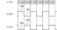
- the surface display unit 100 is controlled by the control unit 300, for example. And as shown in FIG. 2, the surface display part 100 displays 1st information and 2nd information by a time division. Switching between the display of the first information and the second information is performed at, for example, 50 Hz or more, preferably 100 Hz or more.
- FIG. 2 is a diagram for explaining a first example of control performed by the control unit 300.
- the control unit 300 increases the light transmission amount of the first light transmission amount adjustment unit 200 when displaying the first information in a region overlapping at least the region where the information is displayed in the surface display unit 100.
- the light transmission amount of the second light transmission amount adjustment unit 202 is reduced, and when the second information is displayed, the light transmission amount of the second light transmission amount adjustment unit 202 is increased to increase the first light transmission amount adjustment unit.
- the amount of transmitted light of 200 is reduced.
- the control unit 300 maximizes the light transmission amount of the first light transmission amount adjustment unit 200 and minimizes the light transmission amount of the second light transmission amount adjustment unit 202. .
- the control unit 300 maximizes the light transmission amount of the second light transmission amount adjustment unit 202 and minimizes the light transmission amount of the first light transmission amount adjustment unit 200 when the second information is displayed.
- the duty ratio is 50%, but may be a value other than 50%.
- the length of time for which the first information is displayed and the length of time for which the second information is displayed are the same, but they may be different from each other.
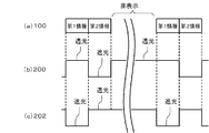
- FIG. 3 is a diagram for explaining a second example of control performed by the control unit 300.
- the control unit 300 increases the light transmission amount of the first light transmission amount adjustment unit 200 (preferably maximum) while the surface display unit 100 is not displaying information, and The light transmission amount of the two light transmission amount adjustment unit 202 is also increased (preferably maximum).
- the surface display unit 100 has translucency, each of the first surface side and the second surface side of the surface display unit 100 when the surface display unit 100 does not display information, The background of the surface display unit 100 can be seen.
- the length of time for which the first information is displayed is the same as the length of time for which the second information is displayed, but they may be different from each other.
- the first light transmission amount adjustment unit 200 is provided on the first surface side of the surface display unit 100, and the second light transmission amount is provided on the second surface side of the surface display unit 100.
- An adjustment unit 202 is provided.
- the first information can be displayed on the first surface side of the surface display unit 100 and the second information can be displayed on the second surface side of the surface display unit 100 at the same time. Moreover, it can suppress that the information being displayed on the surface on the opposite side to the surface which should display information.
- control unit 300 preferably reverses the data output to the surface display unit 100 when displaying the second information with respect to the data output to the surface display unit 100 when displaying the first information. . In this way, information is displayed in the correct orientation for each of the first surface side and the second surface side of the single transmissive surface display unit 100.
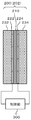
- FIG. 4 is a diagram illustrating the configuration of the first light transmission amount adjustment unit 200 according to the first embodiment.
- the second light transmission amount adjustment unit 202 has the same configuration as the first light transmission amount adjustment unit 200 shown in the drawing.
- the first light transmission amount adjusting unit 200 has a liquid crystal layer 210.
- the first light transmission amount adjusting unit 200 includes a liquid crystal layer 210 and polarizing units 232 and 234.
- the liquid crystal layer 210 is located between the polarizing portions 232 and 234.
- the polarization direction of the polarization unit 232 is orthogonal to the polarization direction of the polarization unit 234.
- the liquid crystal layer 210 is sandwiched between the first electrode 222 and the second electrode 224.
- the first electrode 222 and the second electrode 224 are connected to the control unit 300. That is, the alignment direction of the liquid crystal in the liquid crystal layer 210 is controlled by the control unit 300.
- the first light transmission amount adjustment unit 200 and the second light transmission amount adjustment unit 202 include the liquid crystal layer 210 and the polarization units 232 and 234.
- the control unit 300 can easily control the light transmittance of the first light transmission amount adjusting unit 200 and the light transmittance of the second light transmission amount adjusting unit 202.
- FIG. 5 is a cross-sectional view illustrating configurations of the surface display unit 100, the first light transmission amount adjustment unit 200, and the second light transmission amount adjustment unit 202 included in the display device 10 according to the second embodiment.
- the display device 10 according to the present embodiment is the same as that of any one of the embodiment and the first embodiment except for the configurations of the surface display unit 100, the first light transmission amount adjustment unit 200, and the second light transmission amount adjustment unit 202. It is a configuration.
- the surface display unit 100 is an active organic EL display device, and the organic functional layer 104 is divided into pixel units. That is, the surface display unit 100 has a plurality of light emitting elements (organic EL elements) arranged in a matrix. Specifically, in the surface display unit 100, a plurality of types of light emitting elements that emit different colors (for example, a light emitting element that emits red, a light emitting element that emits green, and a light emitting element that emits blue) are repeatedly arranged. ing.
- a first electrode 102, an organic functional layer 104, a second electrode 106, and a switching element 125 are provided on the first surface side of a light transmitting substrate 110 (an example of a light transmitting layer) of the surface display unit 100. Film-Transistor)) and a wiring connected to the switching element 125 is formed.
- the switching element 125 is controlled by the control unit 300.
- the organic functional layer 104 has at least a hole injection layer, a light emitting layer, and an electron injection layer.
- the organic functional layer 104 may further include at least one of a hole transport layer and an electron transport layer.
- Each layer of the organic functional layer 104 may be formed by an evaporation method or may be formed by a coating method.
- the surface display unit 100 may be a passive organic EL display device.
- the first light transmission amount adjustment unit 200 and the second light transmission amount adjustment unit 202 are both divided into a plurality of regions.
- the control unit 300 can individually control the light transmission amount of the first light transmission amount adjustment unit 200 and the light transmission amount of the second light transmission amount adjustment unit 202 in each of the plurality of regions.
- the second electrode 224 of the first light transmission amount adjustment unit 200 is in pixel units of the surface display unit 100.
- Each of the plurality of second electrodes 224 is connected to a switching element 225, for example, a TFT.
- the switching element 225 is controlled by the control unit 300. That is, the first light transmission amount adjustment unit 200 can control the light transmission amount in units of pixels of the surface display unit 100.
- one second electrode 224 has a plurality of pixels (for example, red color) of the surface display unit 100.
- One light emitting element that emits light, one light emitting element that emits green light, and one light emitting element that emits blue light) may be used.
- the control unit 300 When information is displayed only in a partial area of the surface display unit 100, the control unit 300 is a part of the first light transmission amount adjustment unit 200 and the second light transmission amount adjustment unit 202, specifically, Only the area corresponding to the information display area of the surface display unit 100 performs the control shown in FIG. Then, the control unit 300 increases (for example, maximizes) the light transmission amount for the other regions of the first light transmission amount adjustment unit 200 and the second light transmission amount adjustment unit 202.
- the control unit 300 displays information on the surface display unit 100 among the first light transmission amount adjustment unit 200 and the second light transmission amount adjustment unit 202. Only the portion corresponding to the region is subjected to the control shown in FIG. For this reason, the area
- FIG. 7 is a diagram illustrating configurations of the surface display unit 100, the first light transmission amount adjustment unit 200, and the second light transmission amount adjustment unit 202 included in the display device 10 according to the third embodiment.
- the display device 10 according to the present embodiment has the same configuration as that of the second embodiment except for the configurations of the surface display unit 100 and the first light transmission amount adjustment unit 200.
- the surface display unit 100 is a liquid crystal display panel.
- the second light transmission amount adjustment unit 202 is provided as a part of the surface display unit 100.
- the surface display unit 100 includes a backlight 160, a diffusion layer 150, a liquid crystal layer 114, a filter layer 140, and polarizing units 132 and 134.
- a first electrode 122 is provided on the first surface of the liquid crystal layer 114, and a second electrode 124 is provided on the second surface of the liquid crystal layer 114.
- the second electrode 124 is divided into pixel units.
- a wiring is connected to the second electrode 124 via a switching element 125.
- the filter layer 140 is provided with a plurality of color filters 142 (first color filter group). The color filter 142 overlaps the second electrode 124 in plan view.
- the diffusion layer 150 is provided to diffuse the light from the backlight 160.
- a plurality of slits 152 are provided in the diffusion layer 150.
- the slit 152 is provided in order to give the surface display unit 100 translucency.
- the luminance dynamic range can be expanded by controlling the liquid crystal in the portion where the color filter 142 is not installed when the backlight 160 emits light.
- the first light transmission amount adjusting unit 200 is also provided with a filter layer 240.
- the filter layer 240 has the same configuration as the filter layer 140 of the surface display unit 100 and includes a plurality of color filters 242 (second color filter group).
- the color filter 242 overlaps the second electrode 224 in plan view.
- the filter layers 140 and 240 include areas where the color filters 142 and 242 are not provided. Then, the light transmitted through the slit 152 passes through the area where the color filters 142 and 242 are not provided and the color filters 142 and 242 so that the background of the surface display unit 100 can be seen. Note that when light passes through the color filters 142 and 242, other colors do not transmit, and thus the light transmittance decreases. In order to improve this, slits 152 are also arranged in portions where the color filters 142 and 242 are not provided. This region is at least a part of the light transmitting portion 101 of the surface display unit 100.
- the portion overlapping with the color filters 142 and 242 in a plan view and the portion serving as the translucent portion 101 do not have the diffusion layer 150 (there is a slit 152). , 242 and the part that becomes the translucent part 101. Further, when the backlight 160 is not emitting light, light from the background can be transmitted without being scattered.
- a liquid crystal display panel can be used as the translucent surface display unit 100.
- FIG. 8 is a diagram illustrating configurations of the surface display unit 100, the first light transmission amount adjustment unit 200, and the second light transmission amount adjustment unit 202 included in the display device 10 according to the fourth embodiment.
- the display device 10 according to the present embodiment has the same configuration as the display device 10 according to the third embodiment, except that the surface light emitting unit 170 is provided instead of the backlight 160 and the diffusion layer 150.
- the surface light emitting unit 170 has, for example, a transmissive organic EL layer, and emits light not on a pixel basis but on a surface.
- the color of light emitted from the surface light emitting unit 170 is, for example, white.
- the plurality of color filters 142 first color filter group
- the plurality of color filters 242 second color filter group
Landscapes
- Engineering & Computer Science (AREA)
- Physics & Mathematics (AREA)
- Computer Hardware Design (AREA)
- General Physics & Mathematics (AREA)
- Theoretical Computer Science (AREA)
- Electroluminescent Light Sources (AREA)
- Devices For Indicating Variable Information By Combining Individual Elements (AREA)
Abstract
第1光透過量調整部(200)は、面表示部(100)の第1面側に設けられ、光の透過量を制御する。第2光透過量調整部(202)は、面表示部(100)の第2面側に設けられ、光の透過量を制御する。制御部(300)は、第1情報を表示しているときには第1光透過量調整部(200)の光の透過量を多くして第2光透過量調整部(202)の光の透過量を少なくし、第2情報を表示しているときには第2光透過量調整部(202)の光の透過量を多くして第1光透過量調整部(200)の光の透過量を少なくする。
Description
本発明は、表示装置に関する。
近年は、有機EL(Organic Electroluminescence)表示装置や液晶表示装置など、薄型の表示装置が普及している。
例えば特許文献1において、発光パネルの発光層の一例として有機層を用いることが記載されている。特許文献1には、さらに、両面から光が出射する発光パネルの両面から光を出射させることにより、発光パネルの両面に表示を行うことが記載されている。
特許文献2,3にも、発光パネルの両面に表示を行うことが記載されている。具体的には、特許文献2に記載の技術は、2つの表示素子を重ねることにより一つの発光パネルを形成したものである。また特許文献3に記載の技術は、EL(Electroluminescence)パネルの少なくとも一方の面に液晶調光シートを設けたものである。
本発明者は、一枚の面表示部の両面に、互いに異なる情報を同時に表示することを検討した。このような場合、情報を表示すべき面とは逆側の面に、その情報が表示されることを抑制する必要がある。
本発明が解決しようとする課題としては、一枚の面表示部を用い、両面からの互いに異なる情報を同時に視認することができ、かつ、情報を表示すべき面とは逆側の面にその情報が表示されることを抑制することが一例として挙げられる。
請求項1に記載の発明は、第1面側及び第2面側のそれぞれに光を出射する透光性の面表示部と、
前記面表示部の第1面側に設けられ、光の透過量を制御する第1光透過量調整部と、
前記面表示部の第2面側に設けられ、光の透過量を制御する第2光透過量調整部と、
前記第1光透過量調整部及び前記第2光透過量調整部の光の透過量を制御する制御部と、
を備え、
前記面表示部は、第1情報及び第2情報を時分割で表示し、
前記制御部は、前記面表示部のうち少なくとも情報が表示されている領域と重なる領域において、前記第1情報を表示しているときには前記第1光透過量調整部の光の透過量を多くして前記第2光透過量調整部の光の透過量を少なくし、前記第2情報を表示しているときには前記第2光透過量調整部の光の透過量を多くして前記第1光透過量調整部の光の透過量を少なくする表示装置である。
前記面表示部の第1面側に設けられ、光の透過量を制御する第1光透過量調整部と、
前記面表示部の第2面側に設けられ、光の透過量を制御する第2光透過量調整部と、
前記第1光透過量調整部及び前記第2光透過量調整部の光の透過量を制御する制御部と、
を備え、
前記面表示部は、第1情報及び第2情報を時分割で表示し、
前記制御部は、前記面表示部のうち少なくとも情報が表示されている領域と重なる領域において、前記第1情報を表示しているときには前記第1光透過量調整部の光の透過量を多くして前記第2光透過量調整部の光の透過量を少なくし、前記第2情報を表示しているときには前記第2光透過量調整部の光の透過量を多くして前記第1光透過量調整部の光の透過量を少なくする表示装置である。
上述した目的、およびその他の目的、特徴および利点は、以下に述べる好適な実施の形態、およびそれに付随する以下の図面によってさらに明らかになる。
以下、本発明の実施の形態について、図面を用いて説明する。尚、すべての図面において、同様な構成要素には同様の符号を付し、適宜説明を省略する。
なお、以下に示す説明において、制御部300は、ハードウエア単位の構成ではなく、機能単位のブロックを示している。制御部300は、任意のコンピュータのCPU、メモリ、メモリにロードされたプログラム、そのプログラムを格納するハードディスクなどの記憶メディア、ネットワーク接続用インタフェースを中心にハードウエアとソフトウエアの任意の組合せによって実現される。そして、その実現方法、装置には様々な変形例がある。
(実施形態)
図1は、実施形態に係る表示装置10の構成を示す図である。表示装置10は、面表示部100、第1光透過量調整部200、第2光透過量調整部202、及び制御部300を備えている。
図1は、実施形態に係る表示装置10の構成を示す図である。表示装置10は、面表示部100、第1光透過量調整部200、第2光透過量調整部202、及び制御部300を備えている。
面表示部100は、透光性を有しており、第1面側及び第2面側のそれぞれに、光を出射する。すなわち面表示部100は、第1面側及び第2面側のそれぞれについて情報を表示できる。ここで表示される情報は、動画、静止画、または文字情報などである。面表示部100は、例えば有機EL表示パネルであるが、液晶表示パネルなど、他の方式で情報を表示するものであってもよい。
第1光透過量調整部200は、面表示部100の第1面側に設けられ、光の透過量を制御する。第2光透過量調整部202は、面表示部100の第2面側に設けられ、光の透過量を制御する。
制御部300は、第1光透過量調整部200及び第2光透過量調整部202の光の透過量を制御する。
面表示部100は、例えば制御部300によって制御される。そして図2に示すように、面表示部100は、第1情報及び第2情報を時分割で表示する。第1情報と第2情報の表示の切替は、例えば50Hz以上、好ましくは100Hz以上で行われる。
図2は、制御部300が行う制御の第1例を説明するための図である。制御部300は、面表示部100のうち少なくとも情報が表示されている領域と重なる領域において、第1情報を表示しているときには第1光透過量調整部200の光の透過量を多くして第2光透過量調整部202の光の透過量を少なくし、第2情報を表示しているときには第2光透過量調整部202の光の透過量を多くして第1光透過量調整部200の光の透過量を少なくする。例えば制御部300は、第1情報を表示しているときには第1光透過量調整部200の光の透過量を最大にして、第2光透過量調整部202の光の透過量を最小にする。また、制御部300は、第2情報を表示しているときには第2光透過量調整部202の光の透過量を最大にして、第1光透過量調整部200の光の透過量を最小にする。なお、図2に示す例ではデューティ比を50%としているが、50%以外の値であっても良い。また、第1情報が表示される時間の長さと第2情報が表示される時間の長さを同じにしているが、これらは互いに異なっていても良い。
図3は、制御部300が行う制御の第2例を説明するための図である。本図に示す例において、制御部300は、面表示部100が情報を表示していない間は、第1光透過量調整部200の光の透過量を大きくする(好ましくは最大)とともに、第2光透過量調整部202の光の透過量も大きくする(好ましくは最大)。このようにすると、面表示部100は透光性を有しているため、面表示部100が情報を表示していないときには面表示部100の第1面側及び第2面側のそれぞれにおいて、面表示部100の背景を見ることができる。なお、図3でも、第1情報が表示される時間の長さと第2情報が表示される時間の長さを同じにしているが、これらは互いに異なっていても良い。
以上、本実施形態によれば、面表示部100の第1面側には第1光透過量調整部200が設けられており、面表示部100の第2面側には第2光透過量調整部202が設けられている。このため、面表示部100が第1情報を表示しているときには、面表示部100からの光は、面表示部100の第2面側に出射しにくい。従って、面表示部100の第2面側に第1情報が表示されることを抑制できる。また面表示部100が第2情報を表示しているときには、面表示部100からの光は、面表示部100の第1面側に出射しにくい。従って、面表示部100の第1面側に第2情報が表示されることを抑制できる。
このため、面表示部100の第1面側に第1情報を表示すると同時に、面表示部100の第2面側に第2情報を表示することができる。また、情報を表示すべき面とは逆側の面にその情報が表示されることを抑制することができる。
なお、制御部300は、第2情報を表示するときに面表示部100に出力するデータを、第1情報を表示するときに面表示部100に出力するデータに対して左右反転させるのが好ましい。このようにすると、単一の透過型面表示部100の第1面側及び第2面側のそれぞれについて、正しい向きに情報が表示される。
(実施例1)
図4は、実施例1に係る第1光透過量調整部200の構成を示す図である。なお、第2光透過量調整部202も、本図に示す第1光透過量調整部200と同様の構成を有している。
図4は、実施例1に係る第1光透過量調整部200の構成を示す図である。なお、第2光透過量調整部202も、本図に示す第1光透過量調整部200と同様の構成を有している。
本実施例において、第1光透過量調整部200は液晶層210を有している。詳細には、第1光透過量調整部200は、液晶層210及び偏光部232,234を有している。液晶層210は、偏光部232,234の間に位置している。偏光部232の偏光方向は、偏光部234の偏光方向に直交している。また、液晶層210は第1電極222及び第2電極224によって狭持されている。そして第1電極222及び第2電極224は、制御部300に接続されている。すなわち液晶層210における液晶の配向方向は、制御部300によって制御される。
本実施例によれば、第1光透過量調整部200及び第2光透過量調整部202は、液晶層210及び偏光部232,234を有している。このため、制御部300は、容易に第1光透過量調整部200の光透過率及び第2光透過量調整部202の光透過率を制御することができる。
(実施例2)
図5は、実施例2に係る表示装置10が有する面表示部100、第1光透過量調整部200、及び第2光透過量調整部202の構成を示す断面図である。本実施例に係る表示装置10は、面表示部100、第1光透過量調整部200、及び第2光透過量調整部202の構成を除いて、実施形態及び実施例1のいずれかと同様の構成である。
図5は、実施例2に係る表示装置10が有する面表示部100、第1光透過量調整部200、及び第2光透過量調整部202の構成を示す断面図である。本実施例に係る表示装置10は、面表示部100、第1光透過量調整部200、及び第2光透過量調整部202の構成を除いて、実施形態及び実施例1のいずれかと同様の構成である。
本図に示す例において、面表示部100はアクティブ型の有機EL表示装置であり、有機機能層104が画素単位に分かれている。すなわち面表示部100は、マトリクス状に配置された複数の発光素子(有機EL素子)を有している。詳細には、面表示部100には、互いに異なる色を発光する複数種類の発光素子(例えば赤を発光する発光素子、緑を発光する発光素子、及び青を発光する発光素子)が繰り返し配置されている。そして面表示部100の透光性基板110(透光性層の一例)の第1面側には、第1電極102、有機機能層104、第2電極106、スイッチング素子125(例えばTFT(Thin Film Transistor))、及びスイッチング素子125に接続する配線が形成されている。スイッチング素子125は、制御部300によって制御される。
有機機能層104は、正孔注入層、発光層、及び電子注入層を少なくとも有している。有機機能層104は、さらに正孔輸送層及び電子輸送層の少なくとも一方を有していても良い。有機機能層104の各層は、蒸着法によって形成されていても良いし、塗布法によって形成されていても良い。
なお、面表示部100はパッシブ型の有機EL表示装置であっても良い。
また第1光透過量調整部200及び第2光透過量調整部202は、いずれも複数の領域に分割されている。そして制御部300は、第1光透過量調整部200の光透過量及び第2光透過量調整部202の光の透過量を、複数の領域のそれぞれで個別に制御することができる。
本図に示す例では、第1光透過量調整部200及び第2光透過量調整部202のそれぞれにおいて、第1光透過量調整部200の第2電極224は面表示部100の画素単位に分かれている。そして複数の第2電極224の各々は、スイッチング素子225、例えばTFTに接続されている。スイッチング素子225は、制御部300によって制御される。すなわち第1光透過量調整部200は、面表示部100の画素単位で光透過量を制御することができる。
ただし、図6に示すように、第1光透過量調整部200及び第2光透過量調整部202のそれぞれにおいて、一つの第2電極224は、面表示部100の複数の画素(例えば赤を発光する一つの発光素子、緑を発光する一つの発光素子、及び青を発光する一つの発光素子)を覆う形状及び大きさになっていても良い。
そして面表示部100の一部の領域にのみ情報が表示されている場合、制御部300は、第1光透過量調整部200及び第2光透過量調整部202の一部、具体的には面表示部100の情報表示領域に対応する領域のみ、図2に示した制御を行う。そして制御部300は、第1光透過量調整部200及び第2光透過量調整部202の他の領域については、光の透過量を大きく(例えば最大に)する。
本実施例によっても、実施形態及び実施例1のいずれかと同様の効果を得ることができる。また、制御部300は、面表示部100の一部にのみ情報が表示されている場合、第1光透過量調整部200及び第2光透過量調整部202のうち面表示部100の情報表示領域に対応する部分のみ、図2に示した制御を行う。このため、面表示部100のうち第1光透過量調整部200及び第2光透過量調整部202によって透光性が失われる領域を狭くすることができる。
(実施例3)
図7は、実施例3に係る表示装置10が有する面表示部100、第1光透過量調整部200、及び第2光透過量調整部202の構成を示す図である。本実施例に係る表示装置10は、面表示部100及び第1光透過量調整部200の構成を除いて、実施例2と同様の構成である。
図7は、実施例3に係る表示装置10が有する面表示部100、第1光透過量調整部200、及び第2光透過量調整部202の構成を示す図である。本実施例に係る表示装置10は、面表示部100及び第1光透過量調整部200の構成を除いて、実施例2と同様の構成である。
面表示部100は液晶表示パネルである。そして、第2光透過量調整部202は面表示部100の一部として設けられている。面表示部100は、バックライト160、拡散層150、液晶層114、フィルタ層140、及び偏光部132,134を有している。液晶層114の第1面には第1電極122が設けられており、液晶層114の第2面には第2電極124が設けられている。第2電極124は画素単位に分割されている。そして第2電極124には、スイッチング素子125を介して配線が接続されている。またフィルタ層140には、複数のカラーフィルタ142(第1のカラーフィルタ群)が設けられている。カラーフィルタ142は、平面視で第2電極124と重なっている。
拡散層150は、バックライト160の光を拡散させるために設けられている。そして拡散層150には、複数のスリット152が設けられている。スリット152は、面表示部100に透光性を持たせるために設けられている。
さらに、バックライト160の発光時に、カラーフィルタ142が設置されていない部分の液晶を制御することにより、輝度のダイナミックレンジを拡大することも可能である。
なお、第1光透過量調整部200にも、フィルタ層240が設けられている。フィルタ層240は、面表示部100のフィルタ層140と同様の構成であり、複数のカラーフィルタ242(第2のカラーフィルタ群)を有している。カラーフィルタ242は、平面視で第2電極224と重なっている。
フィルタ層140,240には、カラーフィルタ142,242が設けられていない領域がある。そして、スリット152を透過した光がカラーフィルタ142,242が設けられていない領域及び各カラーフィルタ142,242を透過することにより、面表示部100の背景を見ることができる。なお、光がカラーフィルタ142,242を通ると他の色は透過しないので、光の透過率が低下する。それを改善するために、カラーフィルタ142,242を設けていない部分にもスリット152を配置している。この領域は、面表示部100の透光部101の少なくとも一部となる。
また、平面視でカラーフィルタ142,242と重なる部分、および透光部101となる部分には拡散層150がない(スリット152がある)ので、バックライト160の発光時には、光を各カラーフィルタ142,242および透光部101となる部分に向けて出射することができる。また、バックライト160の非発光時には、背景からの光を散乱させることなく透過させることができる。
本実施例によれば、拡散層150にスリット152を設けているため、透光性の面表示部100として液晶表示パネルを用いることができる。
(実施例4)
図8は、実施例4に係る表示装置10が有する面表示部100、第1光透過量調整部200、及び第2光透過量調整部202の構成を示す図である。本実施例に係る表示装置10は、バックライト160及び拡散層150の代わりに面発光部170を有している点を除いて、実施例3に係る表示装置10と同様の構成である。
図8は、実施例4に係る表示装置10が有する面表示部100、第1光透過量調整部200、及び第2光透過量調整部202の構成を示す図である。本実施例に係る表示装置10は、バックライト160及び拡散層150の代わりに面発光部170を有している点を除いて、実施例3に係る表示装置10と同様の構成である。
面発光部170は、例えば透過型である有機EL層を有しており、画素単位ではなく面で発光する。面発光部170が発光する光の色は、例えば白色である。そして面発光部170を基準にした場合、複数のカラーフィルタ142(第1のカラーフィルタ群)は第1面側に位置しており、複数のカラーフィルタ242(第2のカラーフィルタ群)は第2面側に位置している。
本実施例によっても、実施例2と同様の効果を得ることができる。
以上、図面を参照して実施形態及び実施例について述べたが、これらは本発明の例示であり、上記以外の様々な構成を採用することもできる。
Claims (7)
- 第1面側及び第2面側のそれぞれに光を出射する透光性の面表示部と、
前記面表示部の第1面側に設けられ、光の透過量を制御する第1光透過量調整部と、
前記面表示部の第2面側に設けられ、光の透過量を制御する第2光透過量調整部と、
前記第1光透過量調整部及び前記第2光透過量調整部の光の透過量を制御する制御部と、
を備え、
前記面表示部は、第1情報及び第2情報を時分割で表示し、
前記制御部は、前記面表示部のうち少なくとも情報が表示されている領域と重なる領域において、前記第1情報を表示しているときには前記第1光透過量調整部の光の透過量を多くして前記第2光透過量調整部の光の透過量を少なくし、前記第2情報を表示しているときには前記第2光透過量調整部の光の透過量を多くして前記第1光透過量調整部の光の透過量を少なくする表示装置。 - 請求項1に記載の表示装置において
前記制御部は、前記面表示部を制御し、かつ、前記第2情報を表示するときに前記面表示部に出力するデータを、前記第1情報を表示するときに前記面表示部に出力するデータに対して左右反転させる表示装置。 - 請求項1又は2に記載の表示装置において、
前記制御部は、前記面表示部が情報を表示していないとき、前記第1光透過量調整部及び前記第2光透過量調整部それぞれの光の透過量を大きくする表示装置。 - 請求項1~3のいずれか一項に記載の表示装置において、
前記面表示部は、
透光性基板と、
前記透光性基板の前記第1面側にマトリクス状に配置され、互いに異なる色を発光する複数種類の発光素子と、
を備える表示装置。 - 請求項1~3のいずれか一項に記載の表示装置において、
前記面表示部は、
発光部と、
前記発光部よりも前記第1面側に設けられた第1のカラーフィルタ群と、
前記発光部よりも前記第2面側に設けられた第2のカラーフィルタ群と、
を備える表示装置。 - 請求項1~3のいずれか一項に記載の表示装置において、
前記面表示部は、液晶表示部であり、
前記液晶表示部は、
バックライトと、
前記バックライトの光を散乱させる拡散板と、
を備え、
前記拡散板には複数のスリットが設けられている表示装置。 - 請求項1~6のいずれか一項に記載の表示装置において、
前記第1光透過量調整部及び前記第2光透過量調整部は、それぞれ、
2つの偏光層と
前記2つの偏光層の間に位置する液晶層と、
を備える表示装置。
Priority Applications (1)
| Application Number | Priority Date | Filing Date | Title |
|---|---|---|---|
| PCT/JP2013/054756 WO2014128963A1 (ja) | 2013-02-25 | 2013-02-25 | 表示装置 |
Applications Claiming Priority (1)
| Application Number | Priority Date | Filing Date | Title |
|---|---|---|---|
| PCT/JP2013/054756 WO2014128963A1 (ja) | 2013-02-25 | 2013-02-25 | 表示装置 |
Publications (1)
| Publication Number | Publication Date |
|---|---|
| WO2014128963A1 true WO2014128963A1 (ja) | 2014-08-28 |
Family
ID=51390786
Family Applications (1)
| Application Number | Title | Priority Date | Filing Date |
|---|---|---|---|
| PCT/JP2013/054756 Ceased WO2014128963A1 (ja) | 2013-02-25 | 2013-02-25 | 表示装置 |
Country Status (1)
| Country | Link |
|---|---|
| WO (1) | WO2014128963A1 (ja) |
Cited By (1)
| Publication number | Priority date | Publication date | Assignee | Title |
|---|---|---|---|---|
| WO2025261268A1 (zh) * | 2024-06-20 | 2025-12-26 | 京东方科技集团股份有限公司 | 调光模组及其控制方法、车窗、车辆 |
Citations (4)
| Publication number | Priority date | Publication date | Assignee | Title |
|---|---|---|---|---|
| JP2004199033A (ja) * | 2002-12-06 | 2004-07-15 | Semiconductor Energy Lab Co Ltd | 表示装置とその駆動方法、および電子機器 |
| JP2004327431A (ja) * | 2003-04-07 | 2004-11-18 | Semiconductor Energy Lab Co Ltd | 電子機器 |
| JP2005208125A (ja) * | 2004-01-20 | 2005-08-04 | Toshiba Lsi System Support Kk | 画像表示装置およびそれを搭載した電子機器 |
| JP2006337840A (ja) * | 2005-06-03 | 2006-12-14 | Sharp Corp | 両面表示ディスプレイ装置 |
-
2013
- 2013-02-25 WO PCT/JP2013/054756 patent/WO2014128963A1/ja not_active Ceased
Patent Citations (4)
| Publication number | Priority date | Publication date | Assignee | Title |
|---|---|---|---|---|
| JP2004199033A (ja) * | 2002-12-06 | 2004-07-15 | Semiconductor Energy Lab Co Ltd | 表示装置とその駆動方法、および電子機器 |
| JP2004327431A (ja) * | 2003-04-07 | 2004-11-18 | Semiconductor Energy Lab Co Ltd | 電子機器 |
| JP2005208125A (ja) * | 2004-01-20 | 2005-08-04 | Toshiba Lsi System Support Kk | 画像表示装置およびそれを搭載した電子機器 |
| JP2006337840A (ja) * | 2005-06-03 | 2006-12-14 | Sharp Corp | 両面表示ディスプレイ装置 |
Cited By (1)
| Publication number | Priority date | Publication date | Assignee | Title |
|---|---|---|---|---|
| WO2025261268A1 (zh) * | 2024-06-20 | 2025-12-26 | 京东方科技集团股份有限公司 | 调光模组及其控制方法、车窗、车辆 |
Similar Documents
| Publication | Publication Date | Title |
|---|---|---|
| CN104124261B (zh) | 显示面板 | |
| TWI645237B (zh) | 含有光閥板的液晶顯示器 | |
| US20170170241A1 (en) | Display panel | |
| US20140369072A1 (en) | Transparent Display Apparatus | |
| US9898972B2 (en) | Field-sequential display panel, field-sequential display apparatus and driving method | |
| CN106972041B (zh) | 有机发光二极管显示装置 | |
| US9817267B2 (en) | Liquid crystal displays and the display methods thereof | |
| US10302990B2 (en) | Display cell structure and display device using quantum dot | |
| US9287296B2 (en) | Display device | |
| US11239256B2 (en) | Display substrate, manufacturing method thereof, display panel, and display device | |
| CN102914905A (zh) | 一种彩膜基板及半透半反式液晶显示装置 | |
| CN106094334B (zh) | 显示面板及显示装置 | |
| WO2016043255A1 (ja) | エレクトロルミネッセンス装置、電子デバイス、及びエレクトロルミネッセンス装置の製造方法 | |
| WO2017000450A1 (zh) | 显示驱动方法、显示面板及其制作方法、显示装置 | |
| WO2017028439A1 (zh) | 3d显示装置及其驱动方法 | |
| WO2020073401A1 (zh) | 像素结构、阵列基板及显示装置 | |
| CN106950745A (zh) | 显示装置 | |
| TWI650600B (zh) | 微發光二極體顯示裝置 | |
| US20140110852A1 (en) | Active matrix substrate, and display device | |
| WO2011043094A1 (ja) | 照明装置、及び表示装置 | |
| WO2015024335A1 (zh) | 透明显示装置 | |
| KR20140143046A (ko) | 박막트랜지스터 어레이 기판 및 그의 제조방법 | |
| JP2014022060A (ja) | バックライト装置、表示装置、及びテレビ受信装置 | |
| WO2014128963A1 (ja) | 表示装置 | |
| US10976603B2 (en) | Backlight module and display module |
Legal Events
| Date | Code | Title | Description |
|---|---|---|---|
| 121 | Ep: the epo has been informed by wipo that ep was designated in this application |
Ref document number: 13875959 Country of ref document: EP Kind code of ref document: A1 |
|
| NENP | Non-entry into the national phase |
Ref country code: DE |
|
| 122 | Ep: pct application non-entry in european phase |
Ref document number: 13875959 Country of ref document: EP Kind code of ref document: A1 |
|
| NENP | Non-entry into the national phase |
Ref country code: JP |