WO2014128939A1 - Centrifugal compressor - Google Patents
Centrifugal compressor Download PDFInfo
- Publication number
- WO2014128939A1 WO2014128939A1 PCT/JP2013/054613 JP2013054613W WO2014128939A1 WO 2014128939 A1 WO2014128939 A1 WO 2014128939A1 JP 2013054613 W JP2013054613 W JP 2013054613W WO 2014128939 A1 WO2014128939 A1 WO 2014128939A1
- Authority
- WO
- WIPO (PCT)
- Prior art keywords
- flow
- impeller
- reverse
- intake
- centrifugal compressor
- Prior art date
Links
Images


Classifications
-
- F—MECHANICAL ENGINEERING; LIGHTING; HEATING; WEAPONS; BLASTING
- F04—POSITIVE - DISPLACEMENT MACHINES FOR LIQUIDS; PUMPS FOR LIQUIDS OR ELASTIC FLUIDS
- F04D—NON-POSITIVE-DISPLACEMENT PUMPS
- F04D29/00—Details, component parts, or accessories
- F04D29/66—Combating cavitation, whirls, noise, vibration or the like; Balancing
- F04D29/661—Combating cavitation, whirls, noise, vibration or the like; Balancing especially adapted for elastic fluid pumps
- F04D29/667—Combating cavitation, whirls, noise, vibration or the like; Balancing especially adapted for elastic fluid pumps by influencing the flow pattern, e.g. suppression of turbulence
-
- F—MECHANICAL ENGINEERING; LIGHTING; HEATING; WEAPONS; BLASTING
- F04—POSITIVE - DISPLACEMENT MACHINES FOR LIQUIDS; PUMPS FOR LIQUIDS OR ELASTIC FLUIDS
- F04D—NON-POSITIVE-DISPLACEMENT PUMPS
- F04D29/00—Details, component parts, or accessories
- F04D29/40—Casings; Connections of working fluid
- F04D29/42—Casings; Connections of working fluid for radial or helico-centrifugal pumps
- F04D29/4206—Casings; Connections of working fluid for radial or helico-centrifugal pumps especially adapted for elastic fluid pumps
- F04D29/4213—Casings; Connections of working fluid for radial or helico-centrifugal pumps especially adapted for elastic fluid pumps suction ports
-
- F—MECHANICAL ENGINEERING; LIGHTING; HEATING; WEAPONS; BLASTING
- F04—POSITIVE - DISPLACEMENT MACHINES FOR LIQUIDS; PUMPS FOR LIQUIDS OR ELASTIC FLUIDS
- F04D—NON-POSITIVE-DISPLACEMENT PUMPS
- F04D17/00—Radial-flow pumps, e.g. centrifugal pumps; Helico-centrifugal pumps
- F04D17/08—Centrifugal pumps
- F04D17/10—Centrifugal pumps for compressing or evacuating
-
- F—MECHANICAL ENGINEERING; LIGHTING; HEATING; WEAPONS; BLASTING
- F04—POSITIVE - DISPLACEMENT MACHINES FOR LIQUIDS; PUMPS FOR LIQUIDS OR ELASTIC FLUIDS
- F04D—NON-POSITIVE-DISPLACEMENT PUMPS
- F04D29/00—Details, component parts, or accessories
- F04D29/05—Shafts or bearings, or assemblies thereof, specially adapted for elastic fluid pumps
- F04D29/053—Shafts
-
- F—MECHANICAL ENGINEERING; LIGHTING; HEATING; WEAPONS; BLASTING
- F04—POSITIVE - DISPLACEMENT MACHINES FOR LIQUIDS; PUMPS FOR LIQUIDS OR ELASTIC FLUIDS
- F04D—NON-POSITIVE-DISPLACEMENT PUMPS
- F04D29/00—Details, component parts, or accessories
- F04D29/26—Rotors specially for elastic fluids
- F04D29/28—Rotors specially for elastic fluids for centrifugal or helico-centrifugal pumps for radial-flow or helico-centrifugal pumps
- F04D29/284—Rotors specially for elastic fluids for centrifugal or helico-centrifugal pumps for radial-flow or helico-centrifugal pumps for compressors
-
- F—MECHANICAL ENGINEERING; LIGHTING; HEATING; WEAPONS; BLASTING
- F04—POSITIVE - DISPLACEMENT MACHINES FOR LIQUIDS; PUMPS FOR LIQUIDS OR ELASTIC FLUIDS
- F04D—NON-POSITIVE-DISPLACEMENT PUMPS
- F04D29/00—Details, component parts, or accessories
- F04D29/40—Casings; Connections of working fluid
- F04D29/42—Casings; Connections of working fluid for radial or helico-centrifugal pumps
- F04D29/4206—Casings; Connections of working fluid for radial or helico-centrifugal pumps especially adapted for elastic fluid pumps
-
- F—MECHANICAL ENGINEERING; LIGHTING; HEATING; WEAPONS; BLASTING
- F04—POSITIVE - DISPLACEMENT MACHINES FOR LIQUIDS; PUMPS FOR LIQUIDS OR ELASTIC FLUIDS
- F04D—NON-POSITIVE-DISPLACEMENT PUMPS
- F04D29/00—Details, component parts, or accessories
- F04D29/40—Casings; Connections of working fluid
- F04D29/42—Casings; Connections of working fluid for radial or helico-centrifugal pumps
- F04D29/44—Fluid-guiding means, e.g. diffusers
- F04D29/441—Fluid-guiding means, e.g. diffusers especially adapted for elastic fluid pumps
- F04D29/444—Bladed diffusers
-
- F—MECHANICAL ENGINEERING; LIGHTING; HEATING; WEAPONS; BLASTING
- F04—POSITIVE - DISPLACEMENT MACHINES FOR LIQUIDS; PUMPS FOR LIQUIDS OR ELASTIC FLUIDS
- F04D—NON-POSITIVE-DISPLACEMENT PUMPS
- F04D29/00—Details, component parts, or accessories
- F04D29/66—Combating cavitation, whirls, noise, vibration or the like; Balancing
- F04D29/68—Combating cavitation, whirls, noise, vibration or the like; Balancing by influencing boundary layers
- F04D29/681—Combating cavitation, whirls, noise, vibration or the like; Balancing by influencing boundary layers especially adapted for elastic fluid pumps
- F04D29/685—Inducing localised fluid recirculation in the stator-rotor interface
-
- F—MECHANICAL ENGINEERING; LIGHTING; HEATING; WEAPONS; BLASTING
- F04—POSITIVE - DISPLACEMENT MACHINES FOR LIQUIDS; PUMPS FOR LIQUIDS OR ELASTIC FLUIDS
- F04D—NON-POSITIVE-DISPLACEMENT PUMPS
- F04D25/00—Pumping installations or systems
- F04D25/02—Units comprising pumps and their driving means
- F04D25/024—Units comprising pumps and their driving means the driving means being assisted by a power recovery turbine
-
- F—MECHANICAL ENGINEERING; LIGHTING; HEATING; WEAPONS; BLASTING
- F05—INDEXING SCHEMES RELATING TO ENGINES OR PUMPS IN VARIOUS SUBCLASSES OF CLASSES F01-F04
- F05D—INDEXING SCHEME FOR ASPECTS RELATING TO NON-POSITIVE-DISPLACEMENT MACHINES OR ENGINES, GAS-TURBINES OR JET-PROPULSION PLANTS
- F05D2220/00—Application
- F05D2220/40—Application in turbochargers
-
- F—MECHANICAL ENGINEERING; LIGHTING; HEATING; WEAPONS; BLASTING
- F05—INDEXING SCHEMES RELATING TO ENGINES OR PUMPS IN VARIOUS SUBCLASSES OF CLASSES F01-F04
- F05D—INDEXING SCHEME FOR ASPECTS RELATING TO NON-POSITIVE-DISPLACEMENT MACHINES OR ENGINES, GAS-TURBINES OR JET-PROPULSION PLANTS
- F05D2230/00—Manufacture
- F05D2230/20—Manufacture essentially without removing material
- F05D2230/21—Manufacture essentially without removing material by casting
-
- F—MECHANICAL ENGINEERING; LIGHTING; HEATING; WEAPONS; BLASTING
- F05—INDEXING SCHEMES RELATING TO ENGINES OR PUMPS IN VARIOUS SUBCLASSES OF CLASSES F01-F04
- F05D—INDEXING SCHEME FOR ASPECTS RELATING TO NON-POSITIVE-DISPLACEMENT MACHINES OR ENGINES, GAS-TURBINES OR JET-PROPULSION PLANTS
- F05D2250/00—Geometry
- F05D2250/50—Inlet or outlet
- F05D2250/51—Inlet
-
- F—MECHANICAL ENGINEERING; LIGHTING; HEATING; WEAPONS; BLASTING
- F05—INDEXING SCHEMES RELATING TO ENGINES OR PUMPS IN VARIOUS SUBCLASSES OF CLASSES F01-F04
- F05D—INDEXING SCHEME FOR ASPECTS RELATING TO NON-POSITIVE-DISPLACEMENT MACHINES OR ENGINES, GAS-TURBINES OR JET-PROPULSION PLANTS
- F05D2260/00—Function
- F05D2260/60—Fluid transfer
- F05D2260/606—Bypassing the fluid
-
- F—MECHANICAL ENGINEERING; LIGHTING; HEATING; WEAPONS; BLASTING
- F05—INDEXING SCHEMES RELATING TO ENGINES OR PUMPS IN VARIOUS SUBCLASSES OF CLASSES F01-F04
- F05D—INDEXING SCHEME FOR ASPECTS RELATING TO NON-POSITIVE-DISPLACEMENT MACHINES OR ENGINES, GAS-TURBINES OR JET-PROPULSION PLANTS
- F05D2270/00—Control
- F05D2270/01—Purpose of the control system
- F05D2270/10—Purpose of the control system to cope with, or avoid, compressor flow instabilities
- F05D2270/101—Compressor surge or stall
Definitions
- the present invention relates to a centrifugal compressor provided with an impeller rotated by a rotating shaft, and more particularly to a centrifugal compressor incorporated into an exhaust turbocharger.
- the compressor (centrifugal compressor) of the exhaust turbocharger is a surge of the entire system, as shown in the normal compressor of the performance characteristic comparison table in which the pressure ratio in FIG. 18 is taken on the vertical axis and the flow rate is taken on the horizontal axis. Choking occurs from the surge flow rate (the line on the left side of the figure) that occurs, and it is operated stably in the flow rate range up to the choke flow rate (the line on the right side in the figure) where the flow rate stops increasing.
- a guide vane for generating a swirling flow in the intake air is provided on the upstream side of the centrifugal compressor, and a technique for expanding the operating range of the exhaust turbocharger,
- a technology has been proposed in which a part of the intake gas sucked into the impeller is recirculated to the upstream side of the impeller to expand the operating range of the exhaust turbocharger.
- Patent Document 1 The technique of Patent Document 1 will be briefly described based on FIG. According to FIG. 19, the compressed air is introduced by conducting through the guide vane 03 disposed in the annular air chamber 01 provided in the shroud portion and the suction communication passage 05 opened between the impeller upstream portion and the vicinity of the front edge of the impeller. While making it possible, the circulation flow passage 09 which is conducted by the blowout communication passage 07 opened on the suction port side of the impeller upstream portion and is capable of discharging compressed air, and the flow passage on the upstream side of the blowout communication passage 07 A configuration is disclosed in which an airflow flowing into the middle impeller 011 is turned in the same direction as the impeller 011 and an air flow turning mechanism 013 capable of adjusting a turning amount is provided.
- the operating range can be expanded by adjusting the angle of the guide vanes 015 to control the performance characteristics of the compressor, but the variable mechanism of the guide vanes 015 becomes complicated and the compressor becomes larger, and further, The formation of the gap between the movable portion and the fixed portion has a problem that the compression efficiency is reduced.
- the guide vanes 015 of the airflow turning mechanism 013 are provided so as to generate a swirling flow in the same direction as the rotation direction of the impeller 011, the difference between the impeller leading edge angle and the flow angle at the small flow rate side
- the surging flow rate can be reduced by the reduction of the flow rate and the circulation flow, but the pressure loss due to the internal blade and the circulation flow path can be reduced even at the highest efficiency point on the large flow rate side where improvement of flow is unnecessary.
- the present invention has a simple structure in which the recirculation flow path and the reverse swirl flow generation means of the fixed wing are combined without providing a complicated moving mechanism in the guide vanes. It is an object of the present invention to provide a centrifugal compressor capable of obtaining stable operation in a wide range by expanding the operation range on the large flow rate side.
- the present invention has a housing having an inlet opening in the rotational axis direction of the centrifugal compressor and an intake passage connected to the inlet, and can rotate around the rotation axis inside the housing. And disposed between the impeller and the impeller for compressing the intake gas flowing from the intake port, and the intake port and the impeller inside the housing, the intake gas flowing from the intake port to the rotational direction of the impeller Reverse circulation flow generation means for generating a swirl flow in the opposite direction, and a recirculation flow path communicating the outer peripheral portion of the impeller with the intake passage on the upstream side of the impeller;
- the flow generating means proposes a centrifugal compressor characterized in that it comprises a counter-rotating fixed wing that generates a swirling flow at a constant angle in the direction opposite to the direction of rotation of the impeller.
- the surge flow rate is reduced on the small flow rate side, the surge margin is improved, and the pressure is increased on the large flow rate side.
- the improved ratio can increase the working range.
- the circulation flow rate circulated by the recirculation flow path is determined by the pressure difference between the suction port and the blowout port, and the improvement effect is larger as the circulation flow rate is larger.
- the counter-directed swirling flow causes the load at the impeller inlet end to rise, the suction port pressure to rise, and the circulation flow rate to increase. As a result, the surge flow rate can be reduced and the surge margin can be improved.
- the reverse swirl flow generation means is configured only to have a reverse swirl fixed wing that imparts a reverse swirl flow at a constant angle
- the compressor becomes large in size by a complicated mechanism such as a variable wing mechanism, and further movable.
- the formation of the gap between the portion and the fixed portion can solve the problem of the reduction in the compression efficiency. As a result, the efficiency of the compressor is improved, and the compactness can be achieved, and the in-vehicle performance is improved.
- the inclination angle of the downstream end of the reverse-turn fixed wing is set to a fixed angle within the range of 5 to 45 degrees in the direction opposite to the rotation direction of the impeller.
- FIG. 3 is a graph showing the relationship between the inclination angle of the reverse rotating fixed wing and the working range of the compressor, and in order to secure this working range more than a certain degree, 5 in the direction opposite to the rotation direction of the impeller. It is desirable that the angle be in the range of 45 degrees, and it is particularly preferable that the angle be in the range of 10 degrees to 20 degrees. If it is less than 5 degrees, the effect of reverse flow, that is, the load increase at the blade leading edge of the impeller can not be obtained, and if it exceeds 45 degrees, the load on the blade leading edge of the impeller becomes excessive, so-called stall condition The reason is that
- the reverse-turn fixed wing is circumferentially attached to the inner circumferential wall of the intake passage and a plurality of guide vanes radially disposed in the radial direction of the intake passage, and the plurality of guide vanes It is preferable that an inner cylinder member provided to connect the inner peripheral end portions of the inner cylinder member is formed, and a central intake flow passage is formed inside the inner cylinder member.
- the reverse swirl fixed wing is preferably provided in the intake passage on the upstream side of the outlet of the recirculation flow channel, and by configuring in this way, the flow of the reverse swirl flow is taken into the intake passage. It can be formed broadly and evenly.
- the reverse swirl fixed wing may be provided in the intake passage between the suction port and the blowout port of the recirculation channel, and in this configuration, the recirculation channel is formed. Also for the circulation flow that passes back through, since the reverse swirl fixed wing is passed, the flow of the reverse swirl flow can be generated reliably, and the effect of the reverse swirl flow can be increased.
- the reverse swirl fixed wing and the recirculation flow path may be integrally formed, and thus, the reverse swirl fixed wing and the recirculation flow path may be integrally formed.
- this integral structure may be manufactured by being integrally molded of a resin material or a cast material (cast iron).
- a support or a projection which changes the flow direction of the circulation flow in the direction opposite to the rotation direction of the impeller is provided.
- the circulation flow from the impeller has a swirl component in the same direction as the rotation direction of the impeller. Therefore, by providing a support or projection in the recirculation flow path that changes the flow direction of the circulating flow in the direction opposite to the rotation direction of the impeller, the swing component in the same direction as the impeller is weakened. It is possible to easily generate a swirling flow in the opposite direction to the impeller when it is blown out from the outlet of the recirculation channel and flows into the impeller again, and the effect of the reverse swirling flow can be increased.
- a support column along the rotational axis direction is provided in the recirculation flow channel, and 5 to 20 support columns, preferably 10 to 15 support columns are provided in the circumferential direction.
- the reverse rotation fixed wing, the recirculation passage, and a post or a projection provided in the recirculation passage be integrally formed.
- this integral structure may be manufactured by being integrally molded of a resin material or a cast material (cast iron).
- a high pressure air outlet for supplying high pressure air in the swirling direction of the reverse swirling flow may be provided in the intake passage on the upstream side or downstream side of the reverse swirling flow generating means.
- reverse swirl flow generated by the reverse swirl fixed wing or swirl flow generated by the reverse swirl fixed wing can increase the effect of the reverse swirl flow, and can increase the effect of extending the operating range of the compressor.
- the intake pipe connected to the upstream side of the intake port is configured by a bent pipe so that intake air is swirled in the direction of the reverse swirl flow.
- the intake pipe connected to the upstream side of the intake port can be strengthened by the counter-rotating fixed wing by being configured by the bent pipe so as to generate the counter-rotating flow. Therefore, the effect of the reverse swirl flow can be increased, and the expansion effect of the operating range of the compressor can be increased.
- the compression structure on the small flow rate side and the large flow rate side can be realized in a simple structure combining the recirculation flow path and the reverse swirl flow generation means of the fixed wing without providing a complicated moving mechanism in the guide vanes.
- the operating range of the machine can be expanded and stable operation can be obtained in a wide range.
- It is a 4th embodiment of the present invention shows an example in which a reverse rotation fixed wing and a recirculation channel are formed in one, and is a sectional view of an important part in a rotation axis direction.
- the perspective view outline made into the partial cross section shape of 4th Embodiment is shown.
- the 5th Embodiment of this invention is shown, and it is principal part sectional drawing of a rotating shaft direction.
- 6th Embodiment shows the relationship between the number of support
- the modification of 6th Embodiment is shown.
- the modification of 6th Embodiment is shown.
- the modification of 6th Embodiment is shown.
- the modification of 6th Embodiment is shown.
- the 7th Embodiment of this invention is shown, and it is principal part sectional drawing of a rotating shaft direction. It is AA sectional drawing of FIG.
- the front view of the rotation-axis direction view of the centrifugal compressor of FIG. 17A is shown.
- Performance characteristic comparison chart showing the relationship between pressure ratio and flow rate. It is explanatory drawing which shows a prior art.
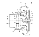
- FIG. 1 shows a cross-sectional view of an essential part of a compressor (centrifugal compressor) 3 side in the rotational axis direction of an exhaust gas turbocharger 1 of an internal combustion engine.
- a compressor centrrifugal compressor
- the rotational force of a turbine rotor (not shown) driven by the exhaust gas of the internal combustion engine is transmitted via the rotating shaft 5.
- an impeller 7 is supported in a compressor housing 9 so as to be rotatable about a rotation axis M of a rotating shaft 5.
- An intake passage 11 for introducing the intake gas before compression, such as air, to the impeller 7 extends in a cylindrical shape concentrically in the direction of the rotation axis M and concentrically.
- An intake port 13 connected to the intake passage 11 is open at an end of the intake passage 11.
- a diffuser 15 extending in a direction perpendicular to the rotation axis M is formed on the outer side of the impeller 7, and a spiral air passage 17 is provided on the outer peripheral side of the diffuser 15.
- the spiral air passage 17 forms an outer peripheral portion of the compressor housing 9.
- the impeller 7 is provided with a hub 19 rotationally driven around the rotation axis M and a plurality of blades (wings) 21 on the outer peripheral surface of the hub 19.
- the hub 19 is coupled to the rotating shaft 5.
- the blades 21 are rotationally driven to suck in air from the air inlet 13 and to compress air that has passed through the air intake passage 11, and the shape is not particularly limited.
- the blade 21 is formed with a front edge 21a which is an upstream edge, a rear edge 21b which is a downstream edge, and an outer peripheral edge (peripheral portion) 21c which is a radially outer edge.
- the peripheral edge 21 c refers to the portion of the side edge covered by the shroud portion 23 of the compressor housing 9.
- the outer peripheral edge 21 c is disposed to pass near the inner surface of the shroud portion 23.
- the impeller 7 of the compressor 3 is rotationally driven around the rotation axis M by the rotational driving force of the rotational shaft 5. Then, external air is drawn in from the intake port 13 and flows between the plurality of blades 21 of the impeller 7, and the dynamic pressure is mainly increased and then flows into the diffuser 15 disposed radially outward. Then, a portion of the dynamic pressure is converted to a static pressure, and the pressure is increased and discharged through the spiral air passage 17. And, it is supplied as intake of an internal combustion engine.
- the recirculation flow path 25 extends along an annular downstream opening 27 opening to the compressor housing 9 facing the outer peripheral edge 21 c of the blade 21 and an inner peripheral wall 29 of the compressor housing 9 upstream of the front edge 21 a of the blade 21. It is provided to communicate with the upstream side opening 31 that opens. Then, a portion of the air immediately after flowing into the space between the blades 21 or the air in the process of pressurization is recirculated into the intake passage 11 on the upstream side of the impeller 7 through the recirculation passage 25. ing.
- the recirculation passage 25 is formed with a cylindrical member 32 centered on the rotation axis M inside the inner peripheral wall 29 of the cylindrical intake passage 11, and the outer peripheral surface 32 a of the cylindrical member 32 and the intake passage 11. And an annular passage formed between the inner circumferential wall 29 and the inner circumferential wall 29 of the Struts are formed so as to connect the outer circumferential surface 32 a of the cylindrical member 32 and the inner circumferential wall 29 of the intake passage 11 at a plurality of locations extending in the recirculation flow path 25 at equal intervals in the circumferential direction and in the rotational axis M direction. 33 are provided.
- the upstream side housing 9a and the downstream side housing 9b form a step-like mating surface, and are positioned and coupled in the rotational axis M direction and the radial direction perpendicular thereto by inlay fitting. ing.
- the provision of the recirculation channel 25 works as follows.
- the air passing through the recirculation flow path 25 flows from the upstream opening 31 toward the downstream opening 27 from the downstream opening 27. , Flows into the outer peripheral edge 21 c of the blade 21.
- the air passing through the recirculation flow path 25 is reversed and flows from the downstream opening 27 toward the upstream opening 31 , Are reintroduced into the intake passage 11 and reintroduced into the impeller 7.
- the flow rate flowing into the front edge 21a of the blade 21 is apparently increased, and the surge flow rate at which surging occurs can be reduced.
- the surge flow rate can be reduced, but at the highest efficiency point where a large flow rate flows, the blades 21 of the impeller 7 at the suction port side or downstream opening 27.
- the flow over the outer peripheral edge (peripheral part) 21c of the is generated to cause the efficiency decrease.
- the reverse swirl flow generation means 41 (intake guide vane) 41 will be described. As shown in FIG. 1, the reverse swirl flow generation means 41 is provided inside the intake passage 11 of the upstream side housing 9 a, disposed between the intake port 13 and the impeller 7, and the air flowing from the intake port 13. The swirling flow is applied to the flow in the opposite direction to the rotation direction of the impeller 7.
- the reverse swirl flow generation means 41 includes a plurality of guide vanes (reverse swirl fixed wings) 43 disposed radially in the radial direction at equal intervals in the circumferential direction on the inner circumferential wall 29 of the upstream housing 9a, and the plurality of guides. And a central portion 45 connecting the inner peripheral ends of the wings 43. Further, regarding the arrangement of the reverse swirl flow generation means 41, since the reverse swirl flow generation means 41 is provided on the upstream side of the upstream opening 31 of the recirculation flow path 25, the flow of the reverse swirl flow is 11 can be formed evenly.
- the guide wing 43 is a plate member having a thin plate-like wing shape, and the inclination angle ⁇ of the trailing edge of the guiding wing 43, that is, the angle of flow flowing out from the trailing edge is the rotation axis
- the range of 5 ° to 45 ° is preferable, assuming that the direction of M is 0 (zero) degree and the direction perpendicular to the rotation axis M is 90 °. . In particular, 10 ° to 20 ° is preferable.
- the working range is expanded by providing the swirl flow in the opposite direction rather than the swirl flow in the same direction as the rotation direction of the impeller 7 on the upstream side of the impeller 7 It was made based on the idea of doing.
- the characteristic in the case of the normal compressor without the recirculation flow passage and the swirl flow generation means is the L1 line
- the L2 line When only recirculation channels are provided, it is the L2 line
- a swirling flow of the same rotation as the impeller is given by the swirl generation means it is the L3 line, and it is reverse rotation to the impeller as in the present invention.
- a swirling flow When a swirling flow is given, it exhibits characteristics like the L4 line.
- the surge flow rate can be reduced by the increase of the recirculation amount on the small flow rate side, and the surge point P2 of the L2 line when only the recirculation passage is provided. Can be reduced to the surge point P3 of the L3 line, but an increase in the recirculation flow rate and a flow over the outer peripheral edge (peripheral part) 21c of the blade 21 of the impeller 7 on the suction port side occur to reduce the pressure ratio. As a result, the L3 line is shown.
- the circulation flow rate circulated by the recirculation flow path 25 is determined by the pressure difference between the suction port and the blowout port.
- the improvement effect is larger, the surge flow rate can be further reduced, and the surge point can be reduced to the surge point P4 of the L4 line. That is, the load on the front edge 21 a side of the blade 21 is increased by the reverse swirl flow, the pressure of the downstream opening 27 which is the suction port is increased, and the pressure difference between the suction port and the discharge port is increased. Circulation flow rate increases.
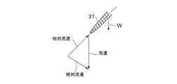
- FIG. 4A corresponds to the rotational flow in the same direction as the rotational direction W of the impeller 7 (absolute flow velocity)
- FIG. 4B corresponds to the reverse direction to the rotational direction W of the impeller 7
- Va, Vb acting on the front edge 21a of the blade 21 is the same as the case of the swirling flow in the same direction.
- the action angle (the angle formed by the center line of the front edge 21 a of the blade 21) ⁇ is large, and the load acting on the blade 21 is large.
- the reduction effect of the surge flow rate by the increase of the recirculation amount is increased.
- the reverse swirl flow generation means 41 has a structure only having a guide vane (reverse swirl fixed wing) 43 that applies a reverse swirl flow at a constant angle
- the compressor has a complex structure such as a variable wing mechanism.
- the increase in size and the formation of a gap between the movable part and the fixed part can solve the problem of reduction in compression efficiency. As a result, the efficiency of the compressor is improved, and the compactness can be achieved, and the in-vehicle performance is improved.
- FIG. 6A shows the relationship with the efficiency
- FIG. 6B shows the relationship with the pressure ratio. In the comparison of 5 to 9 sheets, it was found that the pressure ratio did not change but the efficiency decreased as the number of sheets increased from 5 sheets. Therefore, it was found that 5 to 7 were appropriate.
- the second embodiment is a modification of the guide wing 43 of the first embodiment, and the guide wings 51 of the second embodiment are attached to the inner circumferential wall 29 of the upstream housing 9a at equal intervals along the circumferential direction.
- a plurality of sheets are arranged radially in the radial direction of the intake passage 11.
- an inner cylindrical member 53 provided to connect the inner peripheral end portions of the plurality of guide wings 51 is provided.
- a central intake flow passage 55 is formed which constitutes a fixed wing of reverse rotation by the guide wing 51 and in which the air flowing in from the intake port 13 flows toward the impeller 7 in the direction of the rotation axis M inside the inner cylindrical member 53 Be done.
- the outer diameter of the inner cylindrical member 53 is formed to be larger than the joining position of the front edge 21 a of the blade 21 and the upper surface of the hub 19.
- the third embodiment is a modification of the guide wing 43 of the first embodiment.
- the guide vanes 43 are provided in the intake passage 11 on the upstream side of the upstream opening 31 which is a blowout port of the recirculation flow passage 25.
- the guide vanes 61 are recirculation flow. It is provided in the intake passage 11 between the downstream side opening 65 which is an inlet of the passage 62 and the upstream side opening 67 which is a outlet.
- the guide wings 61 are attached at equal intervals along the circumferential direction to the inner peripheral wall 69a of the cylindrical member 69 forming the recirculation flow path 62 formed in the inner peripheral wall 29 of the downstream side housing 9b, and the diameter of the intake passage 11
- a plurality of guide wings 61 radially arranged in the direction and a central portion 71 provided to connect the inner peripheral end portions of the plurality of guide wings 61 are provided.
- the central portion 71 may be an inner cylinder member as in the second embodiment.
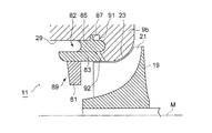
- the fourth embodiment is characterized in that the guide wing 81 is integrally formed with a cylindrical member 83 forming a recirculation channel 82.
- FIG. 9 shows a cross-sectional view of the main part in the rotation axis direction
- FIG. 10 shows a schematic perspective view with a partial cross-sectional shape.
- posts 85 extend in the direction of the rotation axis M and at equal intervals in the circumferential direction, and further, the radial direction of the posts 85
- a stopper portion 87 for positioning is provided in a protruding manner.
- a plurality of guide wings 81 are attached at equal intervals in the circumferential direction in the circumferential direction and provided radially in the radial direction.
- the cylindrical member 83, the support column 85, and the guide wing 81 are integrally formed to form a reverse turning fixed wing unit 89.
- the reverse rotating fixed wing unit 89 is integrally manufactured from a cast material such as a resin material or cast iron.
- the reverse turning fixed wing unit 89 inserted from the side of the intake port 13 along the inner circumferential wall 29 of the intake passage 11 is used for the positioning in the ring groove 91 formed in the downstream side housing 9b.
- the fixing means may be fixed by a bolt not shown, and since no external force particularly acts on the reverse turning fixed wing unit 89, the stopper 87 is engaged with the ring groove 91 without providing the fixing means. It is also possible to fix it alone.
- the structure of the recirculation flow path 82 and the guide wing 81 is simplified, and the manufacturing cost and the number of assembling steps can be reduced.
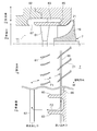
- the guide wing 101 forms an inner cylindrical member 103 and an outer cylindrical member 104 which form the recirculation channel 102. And a structure integrally formed with the guide wing (reverse-turn fixed wing).
- the recirculation flow path 102 is formed between the outer peripheral surface of the inner cylindrical member 103 and the inner peripheral surface of the outer cylindrical member 104, and is formed on the inner peripheral wall 104 a at one end of the outer cylindrical member 104.
- a plurality of guide wings 101 are provided in the circumferential direction, and a step portion 106 is formed on the other end outer peripheral wall 104 b of the outer cylindrical member 104 to form a reverse turning fixed wing unit 108.
- the reverse rotating fixed wing unit 108 is integrally manufactured by a resin material or a cast material.
- the reverse turning fixed wing unit 108 is the inner peripheral wall of the intake passage 11 by inserting and fitting until the step part 106 of the reverse turning fixed wing unit 108 engages with the step part 109 formed on the downstream side housing 9 b. Attached to 29 Thus, the guide vanes 101 can be easily formed in a state in which the recirculation channel 102 is formed while the downstream side opening 110 is formed.
- the structure of the recirculation flow path 102 and the guide vanes 101 is simplified, and the manufacturing cost and the number of assembling steps can be reduced.
- the sixth embodiment is characterized by the shape and number of posts or protrusions formed in the recirculation flow channel in each embodiment.
- FIG. 12 is described based on the configuration of the recirculation flow channel 62 of the third embodiment shown in FIG.
- the flow passage, the guide wing 61, and the blade 21 in plan view FIG. 6 is an explanatory view developed and shown in which the main flow portion 11 a and the circulation portion 11 b are described above and below.
- the airflow F1 of the main flow portion 11 a is swirled by the guide vanes 61 in a direction opposite to the rotational direction W of the impeller 7 and flows between the vanes 21. At this time, it is sucked from the downstream side opening 65 which is the suction port of the recirculation flow channel 62.
- the recirculated flow F2 sucked into the recirculating flow passage 62 has a swirling flow in the same direction as the rotational direction W of the impeller 7, but the swirling flow of the rotation axis M It is corrected in the direction, flows to the upstream opening 67 which is a blowout port, is blown out to the intake passage 11, mixes with the main flow, and flows into the guide wing 61 again.
- a plurality of the columns 63 are installed at equal intervals in the circumferential direction, but usually, about three columns are installed in the circumferential direction to hold the cylindrical member 69 in order to form the recirculation channel 62. It is common to
- FIG. 13 The relationship between the number of columns 63 installed and the expansion effect of the operating range of the compressor 3 is shown in FIG. As shown in FIG. 13, if the number of columns 63 is increased, it is enlarged accordingly, but in order to weaken the turning component in the same direction as the impeller 7 in the recirculation flow channel 62, five or more are installed If it is necessary, the area of contact between the mold and the product will increase and the durability of the mold will decrease during manufacture, so installation of 5 to 20, preferably 10 to 15 should be appropriate. Was found by the test.
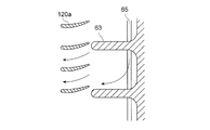
- FIGS. 14A to 14D a modification of the support column 63 and the shape of the guide vane 120 provided on the bottom surface of the recirculation channel 62 to rectify the flow to the upstream opening 67 serving as the outlet.
- a column 63 is formed extending in the direction of the axis of rotation M, and a component of the direction of the axis of rotation M is weakened by weakening a turning component in the same direction as the rotation direction W of the impeller 7 by the column 63 and the guide vanes 120a. It is something to strengthen.
- a column 63 is formed extending in the direction of the rotation axis M, weakens a turning component in the same direction as the rotation direction W of the impeller 7 to strengthen the component in the direction of the rotation axis M, and further by the guide vane 120b. And a component that is opposite to the rotational direction of the impeller 7.
- the shape of the column 63a itself is curved, and the flow along the shape of the column 63a strengthens the component in the direction of the rotation axis M.
- the shape of the support 63b itself is a curved shape, and the flow along the shape of the support 63b imparts an opposite component to the impeller 7.
- the seventh embodiment is a modification of the first embodiment, and as the means for generating a reverse swirling flow in addition to the guide vanes 43, a means for generating a reverse swirling flow in the intake passage 11 with respect to the reverse swirling flow generating means 41 Is generated in the intake passage 11.
- a high pressure air outlet portion 121 is provided in the intake passage 11 on the upstream side of the reverse swirl flow generation means 41.
- the AA cross section of FIG. 15 is shown in FIG.
- high pressure air is spouted from the high pressure air outlet 121 so as to give an opposite swirling flow in the rotational direction of the impeller 7.
- the high pressure air outlet 122 may be provided in the intake passage 11 on the downstream side of the reverse swirl flow generation means 41.
- the eighth embodiment is also a modification of the first embodiment as in the seventh embodiment, and the reverse swirl flow generation means 41 additionally includes a reverse swirl flow in the intake passage 11 in addition to the guide wings 43.
- the shape of the intake pipe 130 connected to the intake passage 11 is a shape that generates a reverse swirl flow.
- An intake pipe 131 connected to the intake port 13 as shown in FIG. 17 is constituted by a bent pipe 132 which is bent twice so that the intake air is swirled in the direction of the reverse swirl flow.
- FIG. 17A shows a side view along the rotational axis direction of the compressor 3
- FIG. 17B shows a front view of the compressor 3 of FIG. 17A in the rotational axis direction
- FIG. 17C shows a perspective view of the compressor 3 of FIG. It shows each.
- the first intake pipe 133, the second intake pipe 134, and the third intake pipe 135 are in a connected state, and the central axis e1 of the first intake pipe 133 and the second axis
- the central axis e2 of the intake pipe 134 is inclined by ⁇ 1
- the central axis e2 of the second intake pipe 134 and the central axis e3 of the third intake pipe 135 are inclined by ⁇ 2 so that the intake pipes are connected.
- the first intake pipe 133, the second intake pipe 134, and the third intake pipe 135 connected to the upstream side of the intake port 13 generate a swirling flow that is reverse to the rotation direction of the impeller 7 as described above. Since the intake flow flowing to the guide vanes 43 is previously made into a reverse swirling flow by being configured by the bent curved tube, the reverse swirling flow generated by the guide vanes 43 can be strengthened, so the working range is expanded. The effect can be made reliably.
- the present invention it is possible to combine the recirculation flow path and the reverse swirl flow generation means without providing a complicated moving mechanism in the guide vanes, and further to provide a fixed wing for reverse swirl, with a simple structure. And, since the operation range of the compressor on the high flow rate side can be expanded and stable operation can be obtained in a wide range, it is useful as an application technique to an exhaust gas turbocharger of an internal combustion engine.
- Exhaust Turbocharger 3 Compressor (Centrifugal Compressor) 5 rotary shaft 7 impeller 9 compressor housing (housing) 9a upstream housing 9b downstream housing 11 intake passage 13 intake port 15 diffuser 19 hub 21 blade 21a blade leading edge 21b blade trailing edge 21c blade peripheral edge 25, 62, 82, 102 recirculation passage 27, 65, 92, 110 downstream side opening 31, 67 upstream side opening 32 cylindrical member 41 reverse swirl flow generation means 25 recirculation flow path 43, 51, 61, 81, 101 guide wing (reverse turning fixed wing) 29 inner circumferential wall 53 inner tubular member 55 central intake flow passage 63, 63a, 63b support column 69, 83 tubular member 87 stopper portion 103 inner tubular member 104 outer tubular member 120a, 120b guide vane (protrusion) 121, 122 High pressure air outlet part 133 1st intake pipe 134 2nd intake pipe 135 3rd intake pipe ⁇ inclination angle of guide wing
Abstract
Description
図19によると、シュラウド部に設けた環状の空気室01に配設するガイドベーン03と、羽根車上流部と羽根車前縁付近の間で開口する吸込連通路05により導通させ圧縮空気を導入可能とすると共に、羽根車上流部の吸込口側で開口する吹出連通路07により導通させ圧縮空気を導出可能に設けた循環流路09と、吹出連通路07よりも上流側の流路に回転中の羽根車011に流入する空気流に羽根車011と同一方向の旋回を与え旋回量調整可能な空気流旋回機構013とを備えた構成が開示されている。 The technique of
According to FIG. 19, the compressed air is introduced by conducting through the
5度より小さいと逆旋回流による効果、すなわち羽根車の羽根前縁部分での負荷上昇が得られず、また45度を超えると羽根車の羽根前縁部分の負荷が過大となり、所謂失速状態を生じてしまうからである。 FIG. 3 is a graph showing the relationship between the inclination angle of the reverse rotating fixed wing and the working range of the compressor, and in order to secure this working range more than a certain degree, 5 in the direction opposite to the rotation direction of the impeller. It is desirable that the angle be in the range of 45 degrees, and it is particularly preferable that the angle be in the range of 10 degrees to 20 degrees.
If it is less than 5 degrees, the effect of reverse flow, that is, the load increase at the blade leading edge of the impeller can not be obtained, and if it exceeds 45 degrees, the load on the blade leading edge of the impeller becomes excessive, so-called stall condition The reason is that
このため、再循環流路内に循環流の流れの方向を前記羽根車の回転方向とは逆方向の向きに変える支柱若しくは突起が設けられることによって、羽根車と同じ向きの旋回成分を弱めることができ、再循環流路の吹き出し口から吹き出して再度羽根車に流入する際に羽根車と逆向きの旋回流を発生しやすくして、逆旋回流による効果を増大できる。 In the vicinity of the inlet of the recirculation channel, the circulation flow from the impeller has a swirl component in the same direction as the rotation direction of the impeller.
Therefore, by providing a support or projection in the recirculation flow path that changes the flow direction of the circulating flow in the direction opposite to the rotation direction of the impeller, the swing component in the same direction as the impeller is weakened. It is possible to easily generate a swirling flow in the opposite direction to the impeller when it is blown out from the outlet of the recirculation channel and flows into the impeller again, and the effect of the reverse swirling flow can be increased.
その結果、再循環流路の吹き出し口から吹き出して再度羽根車に流入する際に羽根車と逆向きの旋回流を発生しやすく逆旋回流による効果を増大でき、コンプレッサの作動範囲の拡大効果を増大できる。 Usually, in order to form a recirculation passage, it is general to arrange about three columns at equal intervals in the circumferential direction in order to hold the inner cylinder part, but 5 to 20, preferably 10 to By installing 15 pieces, it is possible to weaken the turning component in the same direction as the impeller.
As a result, when the air is blown out from the outlet of the recirculation flow path and flows into the impeller again, it is easy to generate a swirling flow opposite to the impeller, the effect of the reverse swirling flow can be increased, and the effect of expanding the working range of the compressor It can be increased.
図1は、内燃機関の排気ターボ過給機1の回転軸方向のコンプレッサ(遠心圧縮機)3側の要部断面図を示す。該排気ターボ過給機1のコンプレッサ3は、内燃機関の排ガスによって駆動される図示しないタービンロータの回転力が、回転軸5を介して伝達されるようになっている。 First Embodiment
FIG. 1 shows a cross-sectional view of an essential part of a compressor (centrifugal compressor) 3 side in the rotational axis direction of an
次に、コンプレッサハウジング9に形成される再循環流路25について説明する。
再循環流路25は、前記羽根21の外周縁21cに対向するコンプレッサハウジング9に開口する環状の下流側開口27と、羽根21の前縁21aより上流側のコンプレッサハウジング9の内周壁29に沿って開口する上流側開口31とを連通するように設けられている。
そして、羽根21間に流入した直後の空気または、加圧途中の空気の一部を、再循環流路25を通って、羽根車7の上流側の吸気通路11内に再循環させるようになっている。 (Recirculation channel)
Next, the
The
Then, a portion of the air immediately after flowing into the space between the
この再循環流路25内には周方向に等間隔に且つ回転軸線M方向に延びて複数個所に、筒状部材32の外周面32aと吸気通路11の内周壁29とを連結するように支柱33が設けられている。 The
Struts are formed so as to connect the outer
コンプレッサ3を通る空気量が適正な流量状態では、再循環流路25を通る空気は、吸気口13からの空気が上流側開口31から下流側開口27に向かって流れて、下流側開口27から、羽根21の外周縁21cに流れ込む。
一方、コンプレッサ3を通る空気量が減少してサージングを生じるような低流量になると、再循環流路25を通る空気は、逆になり、下流側開口27から上流側開口31に向かって流れて、吸気通路11に再導入されて、羽根車7に再導入される。これによって、見かけ上、羽根21の前縁21aに流入する流量が多くなり、サージングが発生するサージ流量を小流量化できる。 The provision of the
When the amount of air passing through the
On the other hand, when the flow rate is low such that the amount of air passing through the
次に、逆旋回流生成手段(吸気ガイドベーン)41について説明する。
図1に示すように、逆旋回流生成手段41は、上流側ハウジング9aの吸気通路11の内部に設けられ、吸気口13と羽根車7との間に配置され、吸気口13から流入する空気流に、羽根車7の回転方向とは逆向きの旋回流を付与する。 (Reverse swirl flow generation means)
Next, the reverse swirl flow generation means (intake guide vane) 41 will be described.
As shown in FIG. 1, the reverse swirl flow generation means 41 is provided inside the
また、この逆旋回流生成手段41の配置に関して、逆旋回流生成手段41は、再循環流路25の上流側開口31よりも上流側に設けられているため、逆旋回流の流れを吸気通路11に満遍なく形成できる。 The reverse swirl flow generation means 41 includes a plurality of guide vanes (reverse swirl fixed wings) 43 disposed radially in the radial direction at equal intervals in the circumferential direction on the inner
Further, regarding the arrangement of the reverse swirl flow generation means 41, since the reverse swirl flow generation means 41 is provided on the upstream side of the
すなわち、逆向きの旋回流によって、羽根21の前縁21a側での負荷が上昇して、吸い込み口である下流側開口27の圧力が上昇し、吸い込み口と吹き出し口との圧力差が増大して循環流量が増大する。 On the other hand, when a swirling flow is given to the reverse rotation side with the
That is, the load on the
従って、図5のL4線のように、小流量側、及び大流量側の両方において、作動範囲が改善されて広い範囲で安定した作動が得られるようになる。 Further, on the large flow rate side, when a turn in the opposite direction to the rotation direction of the
Therefore, as shown by the line L4 in FIG. 5, the operating range is improved on both the low flow side and the high flow side, and a wide range of stable operation can be obtained.
次に、図7を参照して第2実施形態について説明する。
第2実施形態は、第1実施形態の案内翼43の変形例であり、第2実施形態の案内翼51は、上流側ハウジング9aの内周壁29に周方向に沿って等間隔に取り付けられて、吸気通路11の径方向に放射状に複数枚配置されている。また、該複数枚の案内翼51の内周端部を連結するように設けられた内筒部材53を備えている。 Second Embodiment
Next, a second embodiment will be described with reference to FIG.
The second embodiment is a modification of the
その他の構成、作用効果については、第1実施形態と同様である。 Since the flow resistance to the intake air can be reduced by the central
The other configuration and effects are similar to those of the first embodiment.
次に、図8を参照して第3実施形態について説明する。
第3実施形態は、第1実施形態の案内翼43の変形例である。
第1実施形態では、案内翼43は、再循環流路25の吹き出し口である上流側開口31より上流側の吸気通路11に設けられるが、第3実施形態では、案内翼61が再循環流路62の吸い込み口である下流側開口65と吹き出し口である上流側開口67との間の吸気通路11に設けられる。 Third Embodiment
Next, a third embodiment will be described with reference to FIG.
The third embodiment is a modification of the
In the first embodiment, the
次に、図9、10を参照して第4実施形態について説明する。
第4実施形態は、案内翼81が再循環流路82を形成する筒状部材83と一体に形成される構造を特徴とするものである。 Fourth Embodiment
Next, a fourth embodiment will be described with reference to FIGS.
The fourth embodiment is characterized in that the
固定手段については図示しないボルトによって固定してもよく、また、逆旋回固定翼ユニット89には特に外力が作用しないため、固定手段を設けることなく、前記ストッパ部87のリング溝91への係合だけで固定することも可能である。 Therefore, in the fourth embodiment, the reverse turning fixed
The fixing means may be fixed by a bolt not shown, and since no external force particularly acts on the reverse turning fixed
次に、図11を参照して第5実施形態について説明する。
第5実施形態は、第4実施形態と同様に、案内翼(逆旋回固定翼)の構造に関して、案内翼101が、再循環流路102を形成する内側筒状部材103と外側筒状部材104と一体に形成される構造を特徴とするものである。 Fifth Embodiment
Next, a fifth embodiment will be described with reference to FIG.
In the fifth embodiment, as in the fourth embodiment, with respect to the structure of the guide wing (reverse-turn fixed wing), the
これによって、下流側開口110を形成しつつ、再循環流路102を形成した状態で、且つ案内翼101も簡単に形成される。 The reverse turning fixed
Thus, the
次に、図12~図14Dを参照して第6実施形態について説明する。
第6実施形態は、各実施形態における再循環流路内に形成される支柱または突起の形状および本数を特徴とするものである。 Sixth Embodiment
Next, a sixth embodiment will be described with reference to FIGS. 12 to 14D.
The sixth embodiment is characterized by the shape and number of posts or protrusions formed in the recirculation flow channel in each embodiment.
吸気通路11が形成される主流部11aと、再循環流路62が形成される循環部11bとにおける空気の流れ状態を説明するために、流路、案内翼61、及び羽根21を平面視状態に展開して示した説明図であり、主流部11aと、循環部11bとを上下に記載したものである。 FIG. 12 is described based on the configuration of the
In order to explain the flow of air in the
図14Aは、支柱63が回転軸線Mの方向に延びて形成され、支柱63とガイドベーン120aとによって羽根車7の回転方向Wと同じ向きの旋回成分を弱めて回転軸線Mの方向の成分を強めるものである。 Next, referring to FIGS. 14A to 14D, a modification of the
In FIG. 14A, a
次に、図15、16を参照して第7実施形態について説明する。
第7実施形態は、第1実施形態の変形例であり、逆旋回流生成手段41について、案内翼43以外に付加的に吸気通路11内に逆旋回流を生成する手段として、高圧空気旋回流を吸気通路11内に生成するものである。 Seventh Embodiment
Next, a seventh embodiment will be described with reference to FIGS.
The seventh embodiment is a modification of the first embodiment, and as the means for generating a reverse swirling flow in addition to the
また、図15の点線で示すように、逆旋回流生成手段41の下流側の吸気通路11に高圧空気出口部122を設けてもよい。 With such a configuration, it is possible to intensify the reverse swirling flow generated by the
Further, as shown by the dotted line in FIG. 15, the high
次に、図17を参照して第8実施形態について説明する。
第8実施形態についても、前記第7実施形態と同様に、第1実施形態の変形例であり、逆旋回流生成手段41について、案内翼43以外に付加的に吸気通路11内に逆旋回流を生成する手段として、吸気通路11に接続される吸気管130の形状を、逆旋回流を発生させる形状とするものである。 Eighth Embodiment
Next, an eighth embodiment will be described with reference to FIG.
The eighth embodiment is also a modification of the first embodiment as in the seventh embodiment, and the reverse swirl flow generation means 41 additionally includes a reverse swirl flow in the
3 コンプレッサ(遠心圧縮機)
5 回転軸
7 羽根車
9 コンプレッサハウジング(ハウジング)
9a 上流側ハウジング
9b 下流側ハウジング
11 吸気通路
13 吸気口
15 ディフューザ
19 ハブ
21 羽根
21a 羽根の前縁
21b 羽根の後縁
21c 羽根の外周縁
25、62、82、102 再循環流路
27、65、92、110 下流側開口
31、67 上流側開口
32 筒状部材
41 逆旋回流生成手段
25 再循環流路
43、51、61、81、101 案内翼(逆旋回固定翼)
29 内周壁
53 内筒部材
55 中央吸気流通路
63、63a、63b 支柱
69、83 筒状部材
87 ストッパ部
103 内側筒状部材
104 外側筒状部材
120a、120b ガイドベーン(突起)
121、122 高圧空気出口部
133 第1吸気管
134 第2吸気管
135 第3吸気管
θ 案内翼の傾斜角度 1
5
9a
29 inner
121, 122 High pressure
Claims (14)
- 遠心圧縮機の回転軸方向に開口する吸気口と該吸気口につながる吸気通路とを有するハウジングと、
前記ハウジングの内部に、前記回転軸を中心に回転可能に配置され、前記吸気口から流入する吸気ガスを圧縮する羽根車と、
前記ハウジング内部の吸気口と羽根車との間に配置され、前記吸気口から流入する吸気ガスに前記羽根車の回転方向とは逆方向の旋回流を発生させる逆旋回流生成手段と、
前記羽根車の外周部と該羽根車より上流側の前記吸気通路とを連通させる再循環流路と、を備え、
前記逆旋回流生成手段は、前記羽根車の回転方向とは逆方向に一定角度の旋回流を生成する逆旋回固定翼を備えていることを特徴とする遠心圧縮機。 A housing having an intake port opening in the rotational axis direction of the centrifugal compressor and an intake passage connected to the intake port;
An impeller, which is disposed inside the housing so as to be rotatable about the rotation axis, and which compresses intake gas flowing from the intake port;
Reverse swirl flow generation means disposed between the intake port inside the housing and the impeller, for generating a swirl flow in a direction opposite to the rotational direction of the impeller in the intake gas flowing in from the intake port;
And a recirculating flow passage for communicating the outer peripheral portion of the impeller with the intake passage upstream of the impeller.
The centrifugal compressor according to claim 1, wherein the reverse swirl flow generation means includes a reverse swirl fixed wing that generates a swirl flow having a certain angle in a direction opposite to the rotation direction of the impeller. - 前記逆旋回固定翼の下流端の傾斜角度は、羽根車の回転方向とは逆向きに5~45度の範囲内の一定角度に設定されることを特徴とする請求項1記載の遠心圧縮機。 The centrifugal compressor according to claim 1, wherein the inclination angle of the downstream end of the reverse rotation fixed wing is set to a fixed angle within a range of 5 to 45 degrees in a direction opposite to the rotation direction of the impeller. .
- 前記逆旋回固定翼は吸気通路の内周壁に周方向に取り付けられて吸気通路の径方向に放射状に配置された複数枚の案内翼と、該複数枚の案内翼の内周端部を連結するように設けられた内筒部材とを備え、該内筒部材の内部に中央吸気流通路が形成されることを特徴とする請求項1記載の遠心圧縮機。 The reverse-turn fixed wing is connected circumferentially to the inner circumferential wall of the intake passage and connects a plurality of guide vanes radially arranged in the radial direction of the intake passage and the inner peripheral end of the plurality of guide vanes The centrifugal compressor according to claim 1, further comprising an inner cylindrical member provided in such a manner that a central intake flow passage is formed inside the inner cylindrical member.
- 前記逆旋回固定翼が前記再循環流路の吹き出し口より上流側の前記吸気通路に設けられることを特徴とする請求項1記載の遠心圧縮機。 The centrifugal compressor according to claim 1, wherein the reverse rotation fixed wing is provided in the intake passage upstream of the outlet of the recirculation flow passage.
- 前記逆旋回固定翼が前記再循環流路の吸い込み口と吹き出し口との間の前記吸気通路に設けられることを特徴とする請求項1記載の遠心圧縮機。 The centrifugal compressor according to claim 1, wherein the reverse rotation fixed wing is provided in the intake passage between an inlet and an outlet of the recirculation channel.
- 前記逆旋回固定翼と前記再循環流路とが、一体に形成されることを特徴とする請求項4または5記載の遠心圧縮機。 The centrifugal compressor according to claim 4 or 5, wherein the reverse rotation fixed wing and the recirculation flow path are integrally formed.
- 前記一体による構造は、樹脂材料によって成形されることを特徴とする請求項6記載の遠心圧縮機。 The centrifugal compressor according to claim 6, wherein the integral structure is molded of a resin material.
- 前記再循環流路内に循環流の流れの方向を前記羽根車の回転方向とは逆方向の向きに変える支柱若しくは突起が設けられることを特徴とする請求項1記載の遠心圧縮機。 2. The centrifugal compressor according to claim 1, wherein a column or a projection is provided in the recirculation flow path to change the flow direction of the circulation flow in the direction opposite to the rotational direction of the impeller.
- 前記再循環流路内に回転軸方向に沿った支柱が設けられると共に、該支柱が周方向に5~20本、好ましくは10~15本設けられることを特徴とする請求項1記載の遠心圧縮機。 The centrifugal compression according to claim 1, characterized in that in the recirculation flow channel, a column extending in the rotational axis direction is provided, and 5 to 20, preferably 10 to 15 columns are provided in the circumferential direction. Machine.
- 前記逆旋回固定翼と前記再循環流路と該再循環流路内に設けられる支柱若しくは突起とが、一体に形成されることを特徴とする請求項8または9記載の遠心圧縮機。 The centrifugal compressor according to claim 8 or 9, wherein the reverse rotation fixed wing, the recirculation flow channel, and a column or a projection provided in the recirculation flow channel are integrally formed.
- 前記一体による構造は、樹脂材料によって成形されることを特徴とする請求項10記載の遠心圧縮機。 The centrifugal compressor according to claim 10, wherein the integral structure is molded of a resin material.
- 前記逆旋回流生成手段の上流側の吸気通路に、前記逆旋回流の旋回方向に高圧空気を供給する高圧空気出口部を設けたことを特徴とする請求項1記載の遠心圧縮機。 2. The centrifugal compressor according to claim 1, wherein a high pressure air outlet for supplying high pressure air in the swirling direction of the reverse swirling flow is provided in the intake passage upstream of the reverse swirling flow generating means.
- 前記逆旋回流生成手段の下流側の吸気通路に、前記逆旋回流の旋回方向に高圧空気を供給する高圧空気出口部を設けたことを特徴とする請求項1記載の遠心圧縮機。 2. The centrifugal compressor according to claim 1, wherein a high pressure air outlet for supplying high pressure air in the swirling direction of the reverse swirling flow is provided in the intake passage downstream of the reverse swirling flow generating means.
- 前記吸気口の上流側に接続される吸気管が、前記逆旋回流の方向に吸気を旋回させるように曲がり管によって構成されることを特徴とする請求項1記載の遠心圧縮機。 The centrifugal compressor according to claim 1, wherein an intake pipe connected to the upstream side of the intake port is configured by a bent pipe so as to swirl intake air in the direction of the reverse swirl flow.
Priority Applications (5)
| Application Number | Priority Date | Filing Date | Title |
|---|---|---|---|
| CN201380070905.XA CN105026769B (en) | 2013-02-22 | 2013-02-22 | Centrifugal compressor |
| US14/762,167 US10125793B2 (en) | 2013-02-22 | 2013-02-22 | Centrifugal compressor |
| JP2015501202A JP6067095B2 (en) | 2013-02-22 | 2013-02-22 | Centrifugal compressor |
| EP13875422.1A EP2960528B1 (en) | 2013-02-22 | 2013-02-22 | Centrifugal compressor |
| PCT/JP2013/054613 WO2014128939A1 (en) | 2013-02-22 | 2013-02-22 | Centrifugal compressor |
Applications Claiming Priority (1)
| Application Number | Priority Date | Filing Date | Title |
|---|---|---|---|
| PCT/JP2013/054613 WO2014128939A1 (en) | 2013-02-22 | 2013-02-22 | Centrifugal compressor |
Publications (1)
| Publication Number | Publication Date |
|---|---|
| WO2014128939A1 true WO2014128939A1 (en) | 2014-08-28 |
Family
ID=51390762
Family Applications (1)
| Application Number | Title | Priority Date | Filing Date |
|---|---|---|---|
| PCT/JP2013/054613 WO2014128939A1 (en) | 2013-02-22 | 2013-02-22 | Centrifugal compressor |
Country Status (5)
| Country | Link |
|---|---|
| US (1) | US10125793B2 (en) |
| EP (1) | EP2960528B1 (en) |
| JP (1) | JP6067095B2 (en) |
| CN (1) | CN105026769B (en) |
| WO (1) | WO2014128939A1 (en) |
Cited By (4)
| Publication number | Priority date | Publication date | Assignee | Title |
|---|---|---|---|---|
| JPWO2016139800A1 (en) * | 2015-03-05 | 2017-11-16 | 三菱重工業株式会社 | Wastegate valve and turbocharger |
| US11248629B2 (en) | 2017-04-25 | 2022-02-15 | Ihi Corporation | Centrifugal compressor |
| WO2022049773A1 (en) * | 2020-09-07 | 2022-03-10 | 三菱重工エンジン&ターボチャージャ株式会社 | Compressor housing and centrifugal compressor |
| JP7384120B2 (en) | 2020-06-23 | 2023-11-21 | トヨタ紡織株式会社 | Precleaner |
Families Citing this family (19)
| Publication number | Priority date | Publication date | Assignee | Title |
|---|---|---|---|---|
| JP6497183B2 (en) * | 2014-07-16 | 2019-04-10 | トヨタ自動車株式会社 | Centrifugal compressor |
| CN106795821A (en) * | 2014-10-07 | 2017-05-31 | 博格华纳公司 | For the bypass valve of compressor |
| JP6594019B2 (en) * | 2015-04-14 | 2019-10-23 | 三菱重工サーマルシステムズ株式会社 | Inlet guide vane and centrifugal compressor |
| WO2017138199A1 (en) * | 2016-02-12 | 2017-08-17 | 株式会社Ihi | Centrifugal compressor |
| US20170260987A1 (en) * | 2016-03-11 | 2017-09-14 | Daikin Applied Americas Inc. | Centrifugal compressor with casing treatment bypass |
| SE539728C2 (en) * | 2016-03-17 | 2017-11-14 | Scania Cv Ab | A compressor arrangement supplying charged air to a combustion engine |
| WO2017168642A1 (en) * | 2016-03-30 | 2017-10-05 | 三菱重工業株式会社 | Impeller, rotary machine, and turbocharger |
| US9932991B2 (en) * | 2016-04-04 | 2018-04-03 | Ford Global Technologies, Llc | Active swirl device for turbocharger compressor |
| KR102311672B1 (en) * | 2017-03-24 | 2021-10-14 | 현대자동차주식회사 | Compressor |
| KR102215296B1 (en) * | 2017-03-24 | 2021-02-16 | 현대자동차주식회사 | Compressor |
| WO2019004386A1 (en) * | 2017-06-28 | 2019-01-03 | 株式会社Ihi | Centrifugal compressor |
| US10935035B2 (en) * | 2017-10-26 | 2021-03-02 | Hanwha Power Systems Co., Ltd | Closed impeller with self-recirculation casing treatment |
| CN107605804B (en) * | 2017-10-31 | 2019-04-30 | 湘潭大学 | The casing of centrifugal compressor |
| WO2020188770A1 (en) * | 2019-03-19 | 2020-09-24 | 三菱重工エンジン&ターボチャージャ株式会社 | Centrifugal compressor and turbocharger |
| CN113597514B (en) * | 2019-03-19 | 2024-02-09 | 三菱重工发动机和增压器株式会社 | Centrifugal compressor and turbocharger |
| KR20210024336A (en) * | 2019-08-22 | 2021-03-05 | 현대자동차주식회사 | Turbo charger |
| WO2021070499A1 (en) * | 2019-10-09 | 2021-04-15 | 株式会社Ihi | Centrifugal compressor |
| CN112983846A (en) | 2019-12-02 | 2021-06-18 | 开利公司 | Centrifugal compressor and method for operating a centrifugal compressor |
| CN111692131A (en) * | 2020-06-22 | 2020-09-22 | 北京稳力科技有限公司 | Compressor and inlet guide vane device thereof |
Citations (10)
| Publication number | Priority date | Publication date | Assignee | Title |
|---|---|---|---|---|
| JPS5766229U (en) * | 1980-10-07 | 1982-04-20 | ||
| JPS60190942U (en) * | 1984-05-29 | 1985-12-18 | 日野自動車株式会社 | Turbo gear |
| JPS62178799A (en) * | 1985-12-24 | 1987-08-05 | ホルセツト エンジニアリング カンパニ−リミテツド | Compressor |
| JPH06147195A (en) * | 1992-10-30 | 1994-05-27 | Ishikawajima Harima Heavy Ind Co Ltd | Compressor housing of turbo charger |
| JPH11173153A (en) * | 1997-12-10 | 1999-06-29 | Kyoritsu:Kk | Turbo-charger with sliding member |
| JPH11351198A (en) * | 1998-04-06 | 1999-12-21 | Hitachi Ltd | Turbo compressor system |
| JP2004044576A (en) * | 2002-07-13 | 2004-02-12 | Aisin Seiki Co Ltd | Compressor |
| JP2005023792A (en) | 2003-06-30 | 2005-01-27 | Toyota Central Res & Dev Lab Inc | Centrifugal compressor with variable vane |
| JP2006189049A (en) * | 2004-12-30 | 2006-07-20 | Crf Soc Consortile Per Azioni | Device for imparting whirling motion on air flow for supplying turbo-charged internal combustion engine |
| JP2010270641A (en) * | 2009-05-20 | 2010-12-02 | Ihi Corp | Centrifugal compressor |
Family Cites Families (15)
| Publication number | Priority date | Publication date | Assignee | Title |
|---|---|---|---|---|
| US6994518B2 (en) | 2002-11-13 | 2006-02-07 | Borgwarner Inc. | Pre-whirl generator for radial compressor |
| EP1473463B1 (en) * | 2003-04-30 | 2006-08-16 | Holset Engineering Co. Limited | Compressor |
| JP2006002650A (en) | 2004-06-17 | 2006-01-05 | Toyota Motor Corp | Centrifugal compressor interlocking inlet vane with bypass control valve |
| JP2006342682A (en) | 2005-06-07 | 2006-12-21 | Ishikawajima Harima Heavy Ind Co Ltd | Operation range expanding method and device of centrifugal compressor |
| US7475539B2 (en) | 2006-05-24 | 2009-01-13 | Honeywell International, Inc. | Inclined rib ported shroud compressor housing |
| JP2009167938A (en) | 2008-01-17 | 2009-07-30 | Toyota Motor Corp | Turbocharger for internal combustion engine |
| US8272832B2 (en) | 2008-04-17 | 2012-09-25 | Honeywell International Inc. | Centrifugal compressor with surge control, and associated method |
| US9091275B2 (en) | 2009-09-03 | 2015-07-28 | Honeywell International Inc. | Integrated EGR mixer and ported shroud housing compressor |
| US8690524B2 (en) | 2009-10-08 | 2014-04-08 | Honeywell International Inc. | Low-noise ported-shroud compressor for a turbocharger |
| JP5479021B2 (en) | 2009-10-16 | 2014-04-23 | 三菱重工業株式会社 | Exhaust turbocharger compressor |
| US8794914B2 (en) * | 2010-11-23 | 2014-08-05 | GM Global Technology Operations LLC | Composite centrifugal compressor wheel |
| JP5857421B2 (en) | 2011-03-08 | 2016-02-10 | 株式会社Ihi | Turbo compressor |
| CN202280642U (en) | 2011-09-08 | 2012-06-20 | 上海中科高等研究院 | Device for expanding stable running area of centrifugal compressor and centrifugal compressor |
| JP5649758B2 (en) | 2012-08-24 | 2015-01-07 | 三菱重工業株式会社 | Centrifugal compressor |
| US9732756B2 (en) | 2012-08-30 | 2017-08-15 | Mitsubishi Heavy Industries, Ltd. | Centrifugal compressor |
-
2013
- 2013-02-22 US US14/762,167 patent/US10125793B2/en active Active
- 2013-02-22 JP JP2015501202A patent/JP6067095B2/en active Active
- 2013-02-22 WO PCT/JP2013/054613 patent/WO2014128939A1/en active Application Filing
- 2013-02-22 CN CN201380070905.XA patent/CN105026769B/en active Active
- 2013-02-22 EP EP13875422.1A patent/EP2960528B1/en active Active
Patent Citations (10)
| Publication number | Priority date | Publication date | Assignee | Title |
|---|---|---|---|---|
| JPS5766229U (en) * | 1980-10-07 | 1982-04-20 | ||
| JPS60190942U (en) * | 1984-05-29 | 1985-12-18 | 日野自動車株式会社 | Turbo gear |
| JPS62178799A (en) * | 1985-12-24 | 1987-08-05 | ホルセツト エンジニアリング カンパニ−リミテツド | Compressor |
| JPH06147195A (en) * | 1992-10-30 | 1994-05-27 | Ishikawajima Harima Heavy Ind Co Ltd | Compressor housing of turbo charger |
| JPH11173153A (en) * | 1997-12-10 | 1999-06-29 | Kyoritsu:Kk | Turbo-charger with sliding member |
| JPH11351198A (en) * | 1998-04-06 | 1999-12-21 | Hitachi Ltd | Turbo compressor system |
| JP2004044576A (en) * | 2002-07-13 | 2004-02-12 | Aisin Seiki Co Ltd | Compressor |
| JP2005023792A (en) | 2003-06-30 | 2005-01-27 | Toyota Central Res & Dev Lab Inc | Centrifugal compressor with variable vane |
| JP2006189049A (en) * | 2004-12-30 | 2006-07-20 | Crf Soc Consortile Per Azioni | Device for imparting whirling motion on air flow for supplying turbo-charged internal combustion engine |
| JP2010270641A (en) * | 2009-05-20 | 2010-12-02 | Ihi Corp | Centrifugal compressor |
Cited By (6)
| Publication number | Priority date | Publication date | Assignee | Title |
|---|---|---|---|---|
| JPWO2016139800A1 (en) * | 2015-03-05 | 2017-11-16 | 三菱重工業株式会社 | Wastegate valve and turbocharger |
| US10570814B2 (en) | 2015-03-05 | 2020-02-25 | Mitsubishi Heavy Industries Engine & Turbocharger, Ltd. | Waste-gate valve and turbocharger |
| US11248629B2 (en) | 2017-04-25 | 2022-02-15 | Ihi Corporation | Centrifugal compressor |
| JP7384120B2 (en) | 2020-06-23 | 2023-11-21 | トヨタ紡織株式会社 | Precleaner |
| WO2022049773A1 (en) * | 2020-09-07 | 2022-03-10 | 三菱重工エンジン&ターボチャージャ株式会社 | Compressor housing and centrifugal compressor |
| JP7445004B2 (en) | 2020-09-07 | 2024-03-06 | 三菱重工エンジン&ターボチャージャ株式会社 | Compressor housing and centrifugal compressor |
Also Published As
| Publication number | Publication date |
|---|---|
| US20150337863A1 (en) | 2015-11-26 |
| CN105026769B (en) | 2018-08-28 |
| EP2960528A1 (en) | 2015-12-30 |
| US10125793B2 (en) | 2018-11-13 |
| JPWO2014128939A1 (en) | 2017-02-02 |
| JP6067095B2 (en) | 2017-01-25 |
| CN105026769A (en) | 2015-11-04 |
| EP2960528B1 (en) | 2018-12-12 |
| EP2960528A4 (en) | 2016-01-20 |
Similar Documents
| Publication | Publication Date | Title |
|---|---|---|
| WO2014128939A1 (en) | Centrifugal compressor | |
| CN107816440B (en) | Centrifugal compressor | |
| JP5649758B2 (en) | Centrifugal compressor | |
| JP5622965B1 (en) | Centrifugal compressor | |
| CN102705266B (en) | Compressor device | |
| JP6483074B2 (en) | Method for adapting the air flow of a turbine engine with a centrifugal compressor and a diffuser for its implementation | |
| JP5294710B2 (en) | Air reinjection compressor | |
| WO2011045975A1 (en) | Compressor for exhaust turbo-charger | |
| WO2011007467A1 (en) | Impeller and rotary machine | |
| WO2018146753A1 (en) | Centrifugal compressor and turbocharger | |
| WO2012077580A1 (en) | Centrifugal turbomachine | |
| JP6295009B2 (en) | Turbine blade and variable capacity turbine | |
| JP6730917B2 (en) | Centrifugal compressor and turbocharger | |
| JP2009133267A (en) | Impeller of compressor | |
| JP6617837B2 (en) | Variable nozzle unit and turbocharger | |
| WO2019167181A1 (en) | Radial inflow type turbine and turbocharger | |
| US20230272738A1 (en) | Turbine and turbocharger | |
| WO2020188763A1 (en) | Centrifugal compressor and turbocharger | |
| JP2008163761A (en) | Radial turbine |
Legal Events
| Date | Code | Title | Description |
|---|---|---|---|
| WWE | Wipo information: entry into national phase |
Ref document number: 201380070905.X Country of ref document: CN |
|
| 121 | Ep: the epo has been informed by wipo that ep was designated in this application |
Ref document number: 13875422 Country of ref document: EP Kind code of ref document: A1 |
|
| ENP | Entry into the national phase |
Ref document number: 2015501202 Country of ref document: JP Kind code of ref document: A |
|
| WWE | Wipo information: entry into national phase |
Ref document number: 2013875422 Country of ref document: EP |
|
| WWE | Wipo information: entry into national phase |
Ref document number: 14762167 Country of ref document: US |
|
| NENP | Non-entry into the national phase |
Ref country code: DE |