WO2014126236A1 - ガスタービンプラント、及びその運転方法 - Google Patents
ガスタービンプラント、及びその運転方法 Download PDFInfo
- Publication number
- WO2014126236A1 WO2014126236A1 PCT/JP2014/053629 JP2014053629W WO2014126236A1 WO 2014126236 A1 WO2014126236 A1 WO 2014126236A1 JP 2014053629 W JP2014053629 W JP 2014053629W WO 2014126236 A1 WO2014126236 A1 WO 2014126236A1
- Authority
- WO
- WIPO (PCT)
- Prior art keywords
- gas turbine
- water
- steam
- pure water
- turbine plant
- Prior art date
- Legal status (The legal status is an assumption and is not a legal conclusion. Google has not performed a legal analysis and makes no representation as to the accuracy of the status listed.)
- Ceased
Links
Images





Classifications
-
- F—MECHANICAL ENGINEERING; LIGHTING; HEATING; WEAPONS; BLASTING
- F02—COMBUSTION ENGINES; HOT-GAS OR COMBUSTION-PRODUCT ENGINE PLANTS
- F02C—GAS-TURBINE PLANTS; AIR INTAKES FOR JET-PROPULSION PLANTS; CONTROLLING FUEL SUPPLY IN AIR-BREATHING JET-PROPULSION PLANTS
- F02C3/00—Gas-turbine plants characterised by the use of combustion products as the working fluid
- F02C3/20—Gas-turbine plants characterised by the use of combustion products as the working fluid using a special fuel, oxidant, or dilution fluid to generate the combustion products
- F02C3/30—Adding water, steam or other fluids for influencing combustion, e.g. to obtain cleaner exhaust gases
-
- B—PERFORMING OPERATIONS; TRANSPORTING
- B01—PHYSICAL OR CHEMICAL PROCESSES OR APPARATUS IN GENERAL
- B01D—SEPARATION
- B01D3/00—Distillation or related exchange processes in which liquids are contacted with gaseous media, e.g. stripping
- B01D3/007—Energy recuperation; Heat pumps
-
- C—CHEMISTRY; METALLURGY
- C02—TREATMENT OF WATER, WASTE WATER, SEWAGE, OR SLUDGE
- C02F—TREATMENT OF WATER, WASTE WATER, SEWAGE, OR SLUDGE
- C02F1/00—Treatment of water, waste water, or sewage
- C02F1/02—Treatment of water, waste water, or sewage by heating
- C02F1/04—Treatment of water, waste water, or sewage by heating by distillation or evaporation
- C02F1/06—Flash evaporation
-
- C—CHEMISTRY; METALLURGY
- C02—TREATMENT OF WATER, WASTE WATER, SEWAGE, OR SLUDGE
- C02F—TREATMENT OF WATER, WASTE WATER, SEWAGE, OR SLUDGE
- C02F1/00—Treatment of water, waste water, or sewage
- C02F1/02—Treatment of water, waste water, or sewage by heating
- C02F1/04—Treatment of water, waste water, or sewage by heating by distillation or evaporation
- C02F1/16—Treatment of water, waste water, or sewage by heating by distillation or evaporation using waste heat from other processes
-
- C—CHEMISTRY; METALLURGY
- C02—TREATMENT OF WATER, WASTE WATER, SEWAGE, OR SLUDGE
- C02F—TREATMENT OF WATER, WASTE WATER, SEWAGE, OR SLUDGE
- C02F1/00—Treatment of water, waste water, or sewage
- C02F1/44—Treatment of water, waste water, or sewage by dialysis, osmosis or reverse osmosis
- C02F1/441—Treatment of water, waste water, or sewage by dialysis, osmosis or reverse osmosis by reverse osmosis
-
- F—MECHANICAL ENGINEERING; LIGHTING; HEATING; WEAPONS; BLASTING
- F01—MACHINES OR ENGINES IN GENERAL; ENGINE PLANTS IN GENERAL; STEAM ENGINES
- F01K—STEAM ENGINE PLANTS; STEAM ACCUMULATORS; ENGINE PLANTS NOT OTHERWISE PROVIDED FOR; ENGINES USING SPECIAL WORKING FLUIDS OR CYCLES
- F01K17/00—Using steam or condensate extracted or exhausted from steam engine plant
- F01K17/04—Using steam or condensate extracted or exhausted from steam engine plant for specific purposes other than heating
-
- F—MECHANICAL ENGINEERING; LIGHTING; HEATING; WEAPONS; BLASTING
- F02—COMBUSTION ENGINES; HOT-GAS OR COMBUSTION-PRODUCT ENGINE PLANTS
- F02C—GAS-TURBINE PLANTS; AIR INTAKES FOR JET-PROPULSION PLANTS; CONTROLLING FUEL SUPPLY IN AIR-BREATHING JET-PROPULSION PLANTS
- F02C6/00—Plural gas-turbine plants; Combinations of gas-turbine plants with other apparatus; Adaptations of gas-turbine plants for special use
- F02C6/18—Plural gas-turbine plants; Combinations of gas-turbine plants with other apparatus; Adaptations of gas-turbine plants for special use using the waste heat of gas-turbine plants outside the plants themselves, e.g. gas-turbine power heat plants
-
- F—MECHANICAL ENGINEERING; LIGHTING; HEATING; WEAPONS; BLASTING
- F22—STEAM GENERATION
- F22B—METHODS OF STEAM GENERATION; STEAM BOILERS
- F22B1/00—Methods of steam generation characterised by form of heating method
- F22B1/02—Methods of steam generation characterised by form of heating method by exploitation of the heat content of hot heat carriers
- F22B1/18—Methods of steam generation characterised by form of heating method by exploitation of the heat content of hot heat carriers the heat carrier being a hot gas, e.g. waste gas such as exhaust gas of internal-combustion engines
- F22B1/1807—Methods of steam generation characterised by form of heating method by exploitation of the heat content of hot heat carriers the heat carrier being a hot gas, e.g. waste gas such as exhaust gas of internal-combustion engines using the exhaust gases of combustion engines
-
- B—PERFORMING OPERATIONS; TRANSPORTING
- B01—PHYSICAL OR CHEMICAL PROCESSES OR APPARATUS IN GENERAL
- B01D—SEPARATION
- B01D61/00—Processes of separation using semi-permeable membranes, e.g. dialysis, osmosis or ultrafiltration; Apparatus, accessories or auxiliary operations specially adapted therefor
- B01D61/02—Reverse osmosis; Hyperfiltration ; Nanofiltration
- B01D61/025—Reverse osmosis; Hyperfiltration
-
- C—CHEMISTRY; METALLURGY
- C02—TREATMENT OF WATER, WASTE WATER, SEWAGE, OR SLUDGE
- C02F—TREATMENT OF WATER, WASTE WATER, SEWAGE, OR SLUDGE
- C02F2103/00—Nature of the water, waste water, sewage or sludge to be treated
- C02F2103/08—Seawater, e.g. for desalination
-
- C—CHEMISTRY; METALLURGY
- C02—TREATMENT OF WATER, WASTE WATER, SEWAGE, OR SLUDGE
- C02F—TREATMENT OF WATER, WASTE WATER, SEWAGE, OR SLUDGE
- C02F2301/00—General aspects of water treatment
- C02F2301/08—Multistage treatments, e.g. repetition of the same process step under different conditions
-
- C—CHEMISTRY; METALLURGY
- C02—TREATMENT OF WATER, WASTE WATER, SEWAGE, OR SLUDGE
- C02F—TREATMENT OF WATER, WASTE WATER, SEWAGE, OR SLUDGE
- C02F2303/00—Specific treatment goals
- C02F2303/10—Energy recovery
-
- Y—GENERAL TAGGING OF NEW TECHNOLOGICAL DEVELOPMENTS; GENERAL TAGGING OF CROSS-SECTIONAL TECHNOLOGIES SPANNING OVER SEVERAL SECTIONS OF THE IPC; TECHNICAL SUBJECTS COVERED BY FORMER USPC CROSS-REFERENCE ART COLLECTIONS [XRACs] AND DIGESTS
- Y02—TECHNOLOGIES OR APPLICATIONS FOR MITIGATION OR ADAPTATION AGAINST CLIMATE CHANGE
- Y02E—REDUCTION OF GREENHOUSE GAS [GHG] EMISSIONS, RELATED TO ENERGY GENERATION, TRANSMISSION OR DISTRIBUTION
- Y02E20/00—Combustion technologies with mitigation potential
- Y02E20/16—Combined cycle power plant [CCPP], or combined cycle gas turbine [CCGT]
-
- Y—GENERAL TAGGING OF NEW TECHNOLOGICAL DEVELOPMENTS; GENERAL TAGGING OF CROSS-SECTIONAL TECHNOLOGIES SPANNING OVER SEVERAL SECTIONS OF THE IPC; TECHNICAL SUBJECTS COVERED BY FORMER USPC CROSS-REFERENCE ART COLLECTIONS [XRACs] AND DIGESTS
- Y02—TECHNOLOGIES OR APPLICATIONS FOR MITIGATION OR ADAPTATION AGAINST CLIMATE CHANGE
- Y02E—REDUCTION OF GREENHOUSE GAS [GHG] EMISSIONS, RELATED TO ENERGY GENERATION, TRANSMISSION OR DISTRIBUTION
- Y02E20/00—Combustion technologies with mitigation potential
- Y02E20/30—Technologies for a more efficient combustion or heat usage
-
- Y—GENERAL TAGGING OF NEW TECHNOLOGICAL DEVELOPMENTS; GENERAL TAGGING OF CROSS-SECTIONAL TECHNOLOGIES SPANNING OVER SEVERAL SECTIONS OF THE IPC; TECHNICAL SUBJECTS COVERED BY FORMER USPC CROSS-REFERENCE ART COLLECTIONS [XRACs] AND DIGESTS
- Y02—TECHNOLOGIES OR APPLICATIONS FOR MITIGATION OR ADAPTATION AGAINST CLIMATE CHANGE
- Y02P—CLIMATE CHANGE MITIGATION TECHNOLOGIES IN THE PRODUCTION OR PROCESSING OF GOODS
- Y02P70/00—Climate change mitigation technologies in the production process for final industrial or consumer products
- Y02P70/10—Greenhouse gas [GHG] capture, material saving, heat recovery or other energy efficient measures, e.g. motor control, characterised by manufacturing processes, e.g. for rolling metal or metal working
-
- Y—GENERAL TAGGING OF NEW TECHNOLOGICAL DEVELOPMENTS; GENERAL TAGGING OF CROSS-SECTIONAL TECHNOLOGIES SPANNING OVER SEVERAL SECTIONS OF THE IPC; TECHNICAL SUBJECTS COVERED BY FORMER USPC CROSS-REFERENCE ART COLLECTIONS [XRACs] AND DIGESTS
- Y02—TECHNOLOGIES OR APPLICATIONS FOR MITIGATION OR ADAPTATION AGAINST CLIMATE CHANGE
- Y02W—CLIMATE CHANGE MITIGATION TECHNOLOGIES RELATED TO WASTEWATER TREATMENT OR WASTE MANAGEMENT
- Y02W10/00—Technologies for wastewater treatment
- Y02W10/30—Wastewater or sewage treatment systems using renewable energies
Definitions
- the present invention relates to a gas turbine plant including a gas turbine and an operation method thereof.
- This application claims priority based on Japanese Patent Application No. 2013-029304 filed in Japan on February 18, 2013, the contents of which are incorporated herein by reference.
- the gas turbine includes a compressor that compresses air, a combustor that generates combustion gas by burning fuel in the air compressed by the compressor, and a turbine that is driven by the combustion gas.
- This gas turbine has a tendency that its output decreases because the temperature of the air sucked by the compressor becomes high and the mass flow rate of the air sucked by the compressor decreases when the temperature is high such as summer.
- Patent Document 1 when the temperature of the air sucked by the compressor is high, water is supplied to the compressor to suppress a decrease in the output of the gas turbine.
- the water supplied to the compressor is required to be high purity water with few impurities from the viewpoint of continuous operation of the compressor and durability of the compressor.
- a large amount of water is required to obtain steam for increasing the output, and the water supplied to the combustor from the viewpoint of the durability of the combustor is an impurity. It is required to be water with low purity and high purity. For this reason, in any technique, in a region where high-purity water is valuable, such as a desert region, there is a problem that running cost increases if high-purity water is introduced from the outside.
- an object of the present invention is to provide a gas turbine plant capable of suppressing an increase in running cost while obtaining high-purity water, and an operation method thereof.
- a gas turbine plant as one aspect according to the invention for solving the above problems is as follows: A compressor that compresses air; a combustor that generates combustion gas by burning fuel in the air compressed by the compressor; and a gas turbine that includes a turbine driven by the combustion gas; and a gas turbine that is exhausted from the gas turbine. An exhaust heat recovery device that generates steam by the heat of the exhaust gas, and a pure water generator that purifies impure water using the energy of the steam generated by the exhaust heat recovery device. Yes.
- the energy of the steam may be heat of condensation of the steam.
- the impure water can be purified with a small steam mass flow rate.
- any one of the above gas turbine plants at least a part of the pure water which is the water in which the steam is condensed in the pure water generator or the water purified in the pure water generator is compressed. You may provide the gas turbine water supply line which supplies in the said air or the said combustion gas from the intake part of a machine to the inlet of the said turbine.
- pure water can be supplied into the air or the combustion gas from the compressor intake to the turbine inlet. Therefore, the gas turbine plant supplies pure water into the air or combustion gas from the compressor intake to the turbine inlet even if the gas turbine output drops during summer and other high temperatures. By doing so, the mass flow rate of the gas which passes a turbine increases, and the output fall of a gas turbine can be suppressed. That is, the output of the gas turbine can be increased. Moreover, in the gas turbine plant, pure water is generated from the impure water using the energy of the exhaust gas from the gas turbine, so that the running cost can be suppressed as compared with introducing pure water from the outside. .
- the flow rate of fuel supplied to the combustor is controlled in order to suppress the temperature drop at the turbine inlet accompanying the supply of pure water. Will increase.
- the temperature drop at the turbine inlet accompanying the steam supply is small compared to the pure water supply, and thus the increase in the fuel flow rate supplied to the combustor is not large. For this reason, when supplying steam to the combustor to increase the output of the gas turbine, it is necessary to increase the flow rate of the water that forms the steam as compared to supplying water to increase the output of the gas turbine.
- supplying the water to the gas turbine can increase the output of the gas turbine with a smaller amount of water than supplying steam to the gas turbine. Therefore, in the gas turbine plant, the output of the gas turbine can be increased with a smaller amount of water than when steam is supplied to the gas turbine.
- the thermal conductivity of the combustion gas increases, and the thermal conductivity of the wall surface of the combustor and the surface of the turbine blade increases, so that the temperature of the surface of these parts increases.
- the amount of water can be reduced as compared with the case where steam is supplied to the gas turbine. Therefore, the temperature rise of the wall surface of the combustor and the turbine blade surface can be suppressed.
- the shortening of the life of these components can be suppressed. For this reason, in the said gas turbine plant, the increase in running cost can be suppressed also from this viewpoint.
- the pure water may include water obtained by condensing the steam in the pure water generating device.
- at least a part of the pure water may be supplied into the air or the combustion gas between the intermediate stage of the compressor and the inlet of the turbine.
- pure water contains water condensed with steam by a pure water generator. Therefore, in the gas turbine plant, pure water can be easily supplied without using the pressure increasing means even in a relatively high pressure region in the gas turbine or using a simple pressure increasing means. Therefore, according to the gas turbine plant, pure water can be easily supplied also into the air or the combustion gas between the intermediate stage of the compressor and the inlet of the turbine.
- any of the above gas turbine plants at least a part of the pure water which is the water in which the steam is condensed in the pure water generator or the water purified in the pure water generator is used as the gas.
- An external water supply line that supplies the outside of the turbine may be provided.
- pure water can be supplied to the outside.
- the gas turbine water supply line and the external water supply line are connected to each other, and the gas turbine water supply line is connected to the gas turbine water supply line.
- the output of the gas turbine can be adjusted by adjusting the amount of pure water supplied to the gas turbine. Furthermore, in the said gas turbine plant, when the surplus part which is not used for the output increase of a gas turbine arises with the obtained pure water, it can utilize effectively outside by supplying this surplus part outside.
- the gas turbine plant including the control valve further includes a control device that controls an opening degree of the control valve, and the control device closes the control valve when the output of the gas turbine is not increased.
- the pure water may not be supplied into the air or the combustion gas between the intake portion of the compressor and the inlet of the turbine.
- any one of the gas turbine plants provided with the external water supply line not all the water that forms the steam from the exhaust heat recovery device is returned to the exhaust heat recovery device, and the external water supply line is And a water recovery line that supplies at least a part of the pure water supplied to the external water supply line to the exhaust heat recovery device.
- the exhaust heat recovery device can secure water necessary for generating steam.
- the pure water generator vaporizes the water in the impure water by heating the impure water by exchanging heat with the steam from the exhaust heat recovery device.
- the vaporized water may be heat-exchanged with the impure water and cooled to condense into the pure water.
- the pure water generator exchanges heat between the impure water and the steam, It has a plurality of effect cans for condensing the steam, which is subject to heat exchange with the impure water, while heating and converting the water in the impure water into steam, and one effect can out of the plurality of effect cans
- the first effect can is the first effect of the plurality of effect cans by heating the impure water with the steam from the exhaust heat recovery device to heat and heating the impure water to steam.
- the second effect can, which is one effect can excluding the can, cools and condenses the steam generated in the first effect can with the impure water, and condenses it into the purified water. It may be a thing.
- the pure water generating device has three or more effect cans, and among the three or more effect cans, the first effect can and the second effect can.
- the removed effect can may be one in which the steam generated in the other effect cans is heat-exchanged with the impure water and cooled to condense into the purified water.
- the pure water generation device exchanges heat between the impure water and the steam from the exhaust heat recovery device. And heating the impure water heated by the heater to steam under reduced pressure, and allowing the steam to exchange heat with the impure water before being heated by the heater.
- a flash evaporator that cools and condenses into the purified water.
- the pure water generation device includes a casing and a semipermeable membrane that partitions the inside of the casing into two chambers, and one of the two chambers is the first one.
- the impure water and the steam from the exhaust heat recovery device are supplied to a chamber, and the water in the impure water reversely permeates the semipermeable membrane and enters the other second chamber of the two chambers. It may be a reverse osmosis membrane device that is sent as purified water.
- the exhaust heat recovery device includes an exhaust heat recovery boiler that generates steam by heat of exhaust gas exhausted from the gas turbine
- the pure water generation device includes: The impure water may be purified by using at least a part of the energy of the steam generated in the exhaust heat recovery boiler.
- the gas turbine plant preheats the impure water with the heat of the exhaust gas exhausted from the exhaust heat recovery boiler, and sends the preheated impure water to the pure water generator. May be provided.
- the heat of the exhaust gas from the gas turbine can be used more effectively, and the production cost of pure water can be further suppressed.
- the exhaust heat recovery device may include a steam turbine that is driven by using a part of the steam generated in the exhaust heat recovery boiler.
- the impure water is seawater
- a seawater supply pump that supplies the seawater to the pure water generator may be provided.
- An operation method of a gas turbine plant as one aspect according to the invention for solving the above problems is as follows.
- a compressor that compresses air a combustor that generates combustion gas by burning fuel in the air compressed by the compressor, and a gas turbine that includes a turbine driven by the combustion gas.
- an exhaust heat recovery process for generating steam by the heat of the exhaust gas exhausted from the gas turbine, and the energy of the steam generated in the exhaust heat recovery process is used to impure And a pure water generating step for purifying water.
- the energy of the steam may be heat of condensation of the steam.
- the pure water may include water obtained by condensing the steam in the pure water generation step.
- the gas turbine water supply step at least a part of the pure water may be supplied into the air or the combustion gas between the intermediate stage of the compressor and the inlet of the turbine.
- any one of the above operation methods of the gas turbine plant a part of pure water which is water condensed with the steam in the pure water generation step or water purified in the pure water generation step, You may perform the external water supply process supplied outside the said gas turbine.
- pure water can be supplied to the outside.
- the exhaust heat recovery step includes a steam generation step in which steam is generated by the heat of the exhaust gas exhausted from the gas turbine by an exhaust heat recovery boiler, An impure water preheating step of preheating the impure water with heat of exhaust gas exhausted from the exhaust heat recovery boiler, wherein the pure water generation step uses the energy of the steam generated in the steam generation step Then, the impure water preheated in the impure water preheating step may be purified.
- the heat of the exhaust gas from the gas turbine can be used more effectively, and the production cost of pure water can be further suppressed.
- the impure water is seawater
- a seawater supply step of supplying the seawater to a pure water generation device that executes the pure water generation step is executed. May be.
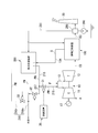
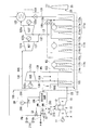
- 1 is a system diagram of a gas turbine plant in a first embodiment according to the present invention. It is a systematic diagram of the exhaust heat recovery device in the first embodiment according to the present invention. It is a systematic diagram of the pure water production
- the gas turbine plant of the present embodiment generates steam by the heat of the gas turbine 10, the generator 17 that generates power by driving the gas turbine 10, and the exhaust gas EG exhausted from the gas turbine 10.
- a seawater supply pump 290 that supplies the pure water generation device 200 and a control device 30 that controls the gas turbine 10 and the like are provided.
- the gas turbine 10 includes a compressor 11 that compresses air, a combustor 12 that generates fuel gas by burning fuel F in the air compressed by the compressor 11, and a turbine 13 that is driven by high-temperature and high-pressure combustion gas. And.
- the turbine rotor of the turbine 13 and the compressor rotor of the compressor 11 rotate about the same rotation axis, and are connected to each other to form a gas turbine rotor.
- the rotor of the generator 17 is connected to this gas turbine rotor.
- the exhaust heat recovery apparatus 100 includes an exhaust heat recovery boiler 110 that generates steam by the heat of combustion gas that drives the turbine 13, that is, exhaust gas EG exhausted from the gas turbine 10, and exhaust heat. Steam turbines 121a, 121b, and 121c driven by steam generated in the recovery boiler 110 and generators 122a, 122b, and 122c that generate electric power by driving the steam turbines 121a, 121b, and 121c are provided. Furthermore, the exhaust heat recovery apparatus 100 includes a condenser 123 that returns the steam that has driven the steam turbine 121 a to water, and a water supply pump 124 that returns the water in the condenser 123 to the exhaust heat recovery boiler 110. Yes.
- the exhaust heat recovery apparatus 100 includes a low-pressure steam turbine 121a, an intermediate-pressure steam turbine 121b, and a high-pressure steam turbine 121c as the steam turbines 121a, 121b, and 121c.
- the exhaust heat recovery boiler 110 includes a low-pressure steam generator 111a that generates low-pressure steam LS, an intermediate-pressure steam generator 111b that generates medium-pressure steam MS, a high-pressure steam generator 111c that generates high-pressure steam HS, And a reheater 115 that heats the steam that has driven the high-pressure steam turbine 121c.
- the low-pressure steam generator 111a, the intermediate-pressure steam generator 111b, and the high-pressure steam generator 111c are all heated by the economizers 112a, 112b, and 112c that heat water and the economizers 112a, 112b, and 112c. It has evaporators 113a, 113b, 113c that convert water into steam, and superheaters 114a, 114b, 114c that superheat the steam generated in the evaporators 113a, 113b, 113c.
- the medium pressure steam generator 111b and the high pressure steam generator 111c are water heated by the economizer 112a of the low pressure steam generator 111a, in addition to the economizers 112b and 112c, the evaporators 113b and 113c, and the superheaters 114b and 114c.
- the economizer 112c of the high-pressure steam generator 111c is the high-pressure economizer 112c
- the evaporator 113c of the high-pressure steam generator 111c is the high-pressure evaporator 113c
- the superheater 114c of the high-pressure steam generator 111c is the high-pressure superheater. 114c.
- the economizer 112b of the intermediate pressure steam generator 111b is an intermediate pressure economizer 112b
- the evaporator 113b of the intermediate pressure steam generator 111b is an intermediate pressure evaporator 113b
- the superheater 114b of the intermediate pressure steam generator 111b is intermediate.
- the pressure superheater 114b is used.
- the economizer 112a of the low-pressure steam generator 111a is the low-pressure economizer 112a
- the evaporator 113a of the low-pressure steam generator 111a is the low-pressure evaporator 113a
- the superheater 114a of the low-pressure steam generator 111a is the low-pressure superheater 114a.
- the pump 116b of the intermediate pressure steam generator 111b is an intermediate pressure pump 116b
- the pump 116c of the high pressure steam generator 111c is a high pressure pump 116c.
- Reheater 115 high pressure superheater 114c, high pressure evaporator 113c, high pressure economizer 112c, medium pressure superheater 114b, medium pressure evaporator 113b, medium pressure economizer 112b, low pressure superheater 114a, low pressure evaporator 113a,
- the low-pressure economizer 112a is arranged in this order toward the downstream side of the exhaust gas EG from the turbine 13 toward the chimney 20.
- the condenser 123 and the low-pressure economizer 112a are connected by a water supply line 131.
- the water supply line 131 is provided with the above-described water supply pump 124.
- the low pressure superheater 114a and the steam inlet of the low pressure steam turbine 121a are connected by a low pressure steam line 132 that sends the low pressure steam LS from the low pressure superheater 114a to the low pressure steam turbine 121a.
- the steam outlet of the low-pressure steam turbine 121 a and the condenser 123 are connected to each other so that the low-pressure steam LS that drives the low-pressure steam turbine 121 a is supplied to the condenser 123.
- the high pressure superheater 114c and the steam inlet of the high pressure steam turbine 121c are connected by a high pressure steam line 138 that sends the high pressure steam HS from the high pressure superheater 114c to the high pressure steam turbine 121c.
- the steam outlet of the high pressure steam turbine 121c and the steam inlet of the reheater 115 are connected by a high pressure steam recovery line 139 that sends the high pressure steam HS from the high pressure steam turbine 121c to the reheater 115.
- the steam outlet of the reheater 115 and the steam inlet of the intermediate pressure steam turbine 121b are connected by a reheat steam line 136 that sends the high pressure steam HS superheated by the reheater 115 to the intermediate pressure steam turbine 121b as the reheat steam RHS.
- An intermediate pressure steam recovery line 137 is connected to the steam outlet of the intermediate pressure steam turbine 121b.
- the intermediate pressure steam recovery line 137 merges with the low pressure steam line 132.
- An intermediate pressure steam line 133 is connected to the steam outlet of the intermediate pressure superheater 114b.
- the intermediate pressure steam line 133 joins the high pressure steam recovery line 139.
- the intermediate pressure steam line 133 branches off as a steam supply line 134 on the way.
- the steam supply line 134 is connected to the pure water generator 200. Therefore, the medium-pressure steam MS from the medium-pressure superheater 114b is supplied to the pure water generation apparatus 200 as the pure water generation steam S.
- the pure water generator 200 and the seawater supply pump 290 are connected by a seawater line 291 as shown in FIG.
- the seawater line 291 is provided with a seawater preheater (impure water preheater) 299 that preheats the seawater SW with the heat of the exhaust gas EG exhausted from the exhaust heat recovery boiler 110.
- the seawater preheater 299 is depicted so as to exist separately with respect to the exhaust heat recovery apparatus 100, but the seawater preheater 299 forms part of the exhaust heat recovery apparatus 100.
- the pure water generating apparatus 200 is an apparatus for converting the seawater SW into purified water (hereinafter referred to as pure water or pure water PW) by a multiple effect method.
- the pure water generating apparatus 200 heat-exchanges the seawater SW and steam to heat the seawater SW to convert the water in the seawater SW into steam, and condenses the steam that is heat exchanged with the seawater SW n (3
- the above-mentioned natural number) effect cans 201 and a condenser 205 that condenses the vapor generated in one of the n effect cans 201 are provided.
- Each of the n effect cans 201 and the condenser 205 includes casings 202 and 206 and heat transfer tubes 203 and 207 disposed in the casings 202 and 206.
- the seawater line 291 has a seawater main line 292 connected to the seawater supply pump 290 and a plurality of seawater branch lines 293 branched from the seawater main line 292.
- One seawater branch line 293 among the plurality of seawater branch lines 293 is connected to the heat transfer pipe 207 of the condenser 205.
- the other seawater branch lines 293 are all connected to the casing 202 of the utility can 201.
- a concentrated seawater discharge line 208 that discharges the concentrated seawater accumulated in the lower part of the effect canister 201 is connected to the lower part of the n effect canisters 201.
- the heat transfer tube 203 of the first effect can 201a which is one of the n effect cans 201, is connected to the steam supply line 134 through which the pure water generating steam S generated by the exhaust heat recovery apparatus 100 flows.
- the heat transfer pipe 203 and the combustor 12 of the gas turbine 10 supply the gas turbine water to guide water condensed through the heat transfer pipe 203 (hereinafter referred to as condensed water or pure water PW) to the combustor 12. Connected by line 215.
- each heat transfer tube 203 of each effect can 201 excluding the first effect can 201a is one effect upstream of the self effect can 201 (the first effect can 201a side).
- the sea water vapor SS generated in the casing 202 is connected by a sea water vapor line 210 that leads to the heat transfer tube 203 of the self-effect can 201.
- each heat transfer tube 203 of each effect can 201 excluding the first effect can 201 a is further connected to an external water supply line 216.
- the external water supply line 216 is connected to external equipment or the like outside the gas turbine 10.
- the casing 202 of the nth effect can 201n and the casing 206 of the condenser 205 are connected by a sea steam line 210 that guides the sea steam SS generated in the casing 202 of the nth effect can 201n into the casing 206 of the condenser 205. ing.
- An external water supply line 216 is further connected to the casing 206 of the condenser 205.
- the gas turbine water supply line 215 and the external water supply line 216 are connected by a connection line 217.
- a first flow rate adjustment valve 31 is provided on the combustor 12 side of the connection position with the connection line 217.
- the connection line 217 is provided with a second flow rate adjustment valve 32. Both of the first flow rate adjustment valve 31 and the second flow rate adjustment valve 32 operate according to instructions from the control device 30.
- the external water supply line 216 is branched into two lines. One of the two lines of the external water supply line 216 forms a plant external water supply line 216o that supplies pure water PW to the outside of the gas turbine plant, and the other line recovers the exhaust heat recovery apparatus 100.
- a water recovery line 216r for returning the pure water PW to the water device 123 (shown in FIG. 3) is formed.
- the water recovery line 216r is provided with a third flow rate adjustment valve 33 for adjusting the flow rate of the pure water PW returned to the condenser 123 having a negative pressure inside.
- the third flow rate adjustment valve 33 is also operated by an instruction from the control device 30.
- the compressor 11 of the gas turbine 10 sucks the air A in the atmosphere, compresses it, and supplies it to the combustor 12.
- the combustor 12 of the gas turbine 10 receives the fuel F from the outside, and burns the fuel F in the air A compressed by the compressor 11 to generate high-temperature and high-pressure combustion gas. This combustion gas is sent to the turbine 13 of the gas turbine 10 to rotate the turbine rotor.
- the generator 17 connected to the gas turbine 10 generates electric power by the rotation of the turbine rotor.
- the combustion gas that has rotated the turbine rotor is exhausted from the gas turbine 10 as exhaust gas EG, and is released from the chimney 20 to the atmosphere via the exhaust heat recovery boiler 110.
- the exhaust heat recovery apparatus 100 recovers the heat contained in the exhaust gas EG in the process in which the exhaust gas EG from the gas turbine 10 passes through the exhaust heat recovery boiler 110 (exhaust heat recovery step (S10)).
- this exhaust heat recovery step (S10) water from the condenser 123 is supplied through the water supply line 131 to the low pressure economizer 112a on the most downstream side (chimney 20 side) in the exhaust heat recovery boiler 110. Is done.
- the low pressure economizer 112a heats this water by exchanging heat with the exhaust gas EG.
- a part of the water heated by the low pressure economizer 112a is further heated by the low pressure evaporator 113a to become steam.
- This steam is further heated by the low-pressure superheater 114a and supplied as low-pressure steam LS to the low-pressure steam turbine 121a via the low-pressure steam line 132 (steam generation process).
- the low-pressure steam turbine 121a is driven, and the generator 122a connected to the low-pressure steam turbine 121a generates power.
- the steam that has driven the low-pressure steam turbine 121 a returns to water in the condenser 123. This water is supplied again from the condenser 123 to the low-pressure economizer 112 a through the water supply line 131.
- the other part of the water heated by the low pressure economizer 112a is pressurized by the medium pressure pump 116b and sent to the medium pressure economizer 112b, and the remaining water heated by the low pressure economizer 112a is It is pressurized by the high pressure pump 116c and sent to the high pressure economizer 112c.
- the high-pressure economizer 112c heats the water sent from the high-pressure pump 116c by exchanging heat with the exhaust gas EG.
- the water heated by the high pressure economizer 112c is further heated by the high pressure evaporator 113c to become steam.
- This steam is further heated by the high-pressure superheater 114c and supplied as high-pressure steam HS to the high-pressure steam turbine 121c via the high-pressure steam line 138 (steam generation process).
- steam turbine 121c is driven, and the generator 122c connected to the high-pressure steam turbine 121c generates power.
- the medium pressure economizer 112b heats the water sent from the medium pressure pump 116b by exchanging heat with the exhaust gas EG.
- the water heated by the medium pressure economizer 112b is further heated by the intermediate pressure evaporator 113b to become steam.
- This steam is further superheated by the intermediate pressure superheater 114b, and a part of the steam is converted to an intermediate pressure steam MS, via the intermediate pressure steam line 133 and the high pressure steam recovery line 139, in the most upstream side of the exhaust heat recovery boiler 110 ( It is sent to the reheater 115 on the gas turbine 10 side.
- the remainder of the steam superheated by the intermediate pressure superheater 114b is sent to the pure water generation apparatus 200 as the pure water generation steam S through the intermediate pressure steam line 133 and the steam supply line 134 (steam generation process). .
- the high-pressure steam HS driving the high-pressure steam turbine 121c and the medium-pressure steam MS from the intermediate-pressure superheater 114b are most upstream (gas turbine 10 side) in the exhaust heat recovery boiler 110 via the high-pressure steam recovery line 139.
- the reheater 115 heats this steam with the exhaust gas EG and superheats it, and supplies it as reheated steam RHS to the intermediate pressure steam turbine 121b via the reheated steam line 136 (steam generation process).
- the intermediate pressure steam turbine 121b is driven, and the generator 122b connected to the intermediate pressure steam turbine 121b generates power.
- the reheated steam RHS that has driven the intermediate pressure steam turbine 121b is supplied to the low pressure steam turbine 121a via the intermediate pressure steam recovery line 137 and the low pressure steam line 132.
- the seawater supply pump 290 pumps up the seawater SW in parallel with the above-described exhaust heat recovery step (S10), and supplies the seawater SW to the pure water generator 200 via the seawater line 291 (seawater supply step (S11)). )).
- the seawater SW pumped up in the seawater supply step (S11) is preheated by heat exchange with the exhaust gas EG discharged from the exhaust heat recovery boiler 110 in the process of passing through the seawater preheater 299 (impure water preheating). Process).
- the exhaust heat recovery step (S10) includes this impure water preheating step.
- the pure water generation apparatus 200 generates pure water, that is, pure water PW, from the seawater SW preheated by the seawater preheater 299 using the thermal energy of the pure water generation steam S from the exhaust heat recovery apparatus 100. (Pure water generation step (S12)).
- seawater SW from the seawater line 291 is supplied into each casing 202 of the n effect cans 201.
- the seawater SW from the seawater line 291 is also supplied to the heat transfer pipe 207 of the condenser 205.
- the pure water generating steam S from the exhaust heat recovery apparatus 100 is supplied to the heat transfer pipe 203 of the first effect can 201a through the steam supply line 134.
- the seawater SW supplied into the casing 202 of the first effect can 201a is heated by heat exchange with the pure water generating steam S in the heat transfer tube 203 of the first effect can 201a, and the water in the seawater SW becomes steam ( Sea water vapor SS).
- the sea water vapor SS is supplied to the heat transfer tube 203 of the second effect can 201b through the sea water vapor line 210.
- the pure water generating steam S in the heat transfer tube 203 of the first effect can 201a is cooled by heat exchange with the seawater SW supplied into the casing 202 of the first effect can 201a, and purified water PW (condensed water) ) This pure water PW flows to the gas turbine water supply line 215.
- seawater SS is evaporated using the condensation heat of the pure water generating steam S. Since the condensation heat of steam is latent heat, it has higher energy than sensible heat. For this reason, in the gas turbine plant of this embodiment, seawater SW which is impure water can be made into steam with a small mass flow rate of steam.
- the inside of the casing 202 of the second effect can 201b is kept at a lower pressure than the inside of the casing 202 of the first effect can 201a.
- the sea water vapor SS is supplied into the heat transfer tube 203 of the second effect can 201b at a pressure close to that in the casing 202 of the first effect can 201a.
- the boiling point of the sea water vapor SS in the heat transfer tube 203 of the second effect can 201b is higher than the boiling point of the seawater SW supplied into the casing 202 of the second effect can 201b.
- the sea water vapor SS in the heat transfer tube 203 of the second effect can 201b is cooled by heat exchange with the seawater SW supplied into the casing 202 of the second effect can 201b, and condensed to be pure water PW (pure water). ).
- the pure water PW flows from the heat transfer tube 203 of the second effect can 201b into the external water supply line 216.
- the seawater SW supplied into the casing 202 of the second effect can 201b is heated by heat exchange with the sea water vapor SS in the heat transfer tube 203 of the second effect can 201b, and the water in the seawater SW is converted into the sea water steam SS. It becomes.
- the sea water vapor SS is supplied to the heat transfer tube 203 of the third effect can 201c through the sea water vapor line 210.
- the seawater SW concentrated in the casing 202 of each effect can 201 is appropriately discharged to the outside, for example, the sea, through the concentrated seawater discharge line 208.
- the pressure in the casing 202 is kept lower toward the downstream side (the side closer to the nth effect can 201n), and the third effect can 201c to the nth effect can In the can 201n, the generation of the sea water vapor SS and the generation of pure water PW (pure water) are performed in the same manner as in the processing in the second effect can 201b.
- the sea water vapor SS supplied from the n-th effect can 201n into the casing 206 of the condenser 205 is cooled by heat exchange with the seawater SW in the heat transfer pipe 207 of the condenser 205, condensed, and purified water PW (pure water) ).
- This pure water PW flows from the casing 206 of the condenser 205 to the external water supply line 216.
- the seawater SW in the heat transfer tube 207 of the condenser 205 is heated by heat exchange with the sea water vapor SS in the casing 206 of the condenser 205 and then discharged to the outside, for example, the sea.
- the seawater SW is used as a heat exchange target with the sea water vapor SS supplied into the casing 206 of the condenser 205, but another cooling medium may be used instead of the seawater SW.
- the above is the processing content in the pure water generation step (S12). According to this process, after evaporating water in seawater simply using steam, n times as much pure water as in the case of cooling and condensing can be obtained.
- the pure water PW (pure water) generated by each of the effect cans 201 and the condenser 205 of the pure water generator 200 is supplied to the outside via the external water supply line 216 (external water supply step (S17)). ). Part of the pure water PW supplied to the external water supply line 216 returns to the condenser 123 of the exhaust heat recovery apparatus 100 via the water recovery line 216r. At this time, the control device 30 adjusts the third flow rate so that the pure water PW corresponding to the mass flow rate of the pure water generating steam S supplied from the exhaust heat recovery boiler 110 to the pure water generating device 200 returns to the condenser 123. The valve opening degree of the valve 33 is controlled. The remaining pure water PW supplied to the external water supply line 216 is supplied to the outside of the gas turbine plant via the plant external water supply line 216o. Outside, for example, the pure water PW is used for beverages, agriculture, industry, sales, and the like.
- the control device 30 controls the gas turbine output by adjusting the amount of fuel supplied to the combustor 12 of the gas turbine 10 and controlling the amount of water supplied.
- the gas turbine 10 has a tendency that the output of the gas turbine 10 decreases because the temperature of the air sucked by the compressor 11 becomes high and the mass flow rate of the air sucked by the compressor 11 decreases when the temperature is high such as summer. Further, the gas turbine 10 may be required to temporarily increase its output. Therefore, the control device 30 determines whether or not the gas turbine output should be increased based on the outside air temperature, the output of the generator 17 and the like (S14). When determining that the gas turbine output should be increased, the control device 30 determines the flow rate of pure water PW (condensed water) supplied to the combustor 12 so that the gas turbine output increases to the target output.
- pure water PW condensed water
- the control device 30 sends a control signal indicating the valve opening corresponding to the flow rate to the first flow rate adjustment valve 31 provided in the gas turbine water supply line 215.
- the first flow rate adjustment valve 31 opens to an opening degree corresponding to the valve opening degree indicated by the control signal (S15).
- the control apparatus 30 is the flow volume of the pure water PW (condensed water) except the pure water PW (condensed water) supplied to the combustor 12 among the pure water PW (condensed water) from the pure water generator. That is, the flow rate of excess pure water PW (condensed water) is obtained.
- the control device 30 sends a control signal indicating the valve opening degree corresponding to the flow rate to the second flow rate adjustment valve 32 provided in the connection line 217.
- the second flow rate adjustment valve 32 receives this control signal, the second flow rate adjustment valve 32 has an opening degree corresponding to the valve opening degree indicated by the control signal, and flows excess pure water PW (condensed water) to the external water supply line 216.
- the pure water generating steam S condensed in the heat transfer tube 203 of the first effect can 201a of the pure water generating apparatus 200 is combusted as pure water PW (condensed water) via the gas turbine water supply line 215. 12 (gas turbine water supply step (S18)).
- pure water PW condensed water
- the amount of fuel supplied to the combustor 12 is increased in order to suppress the temperature drop at the turbine inlet accompanying the water supply, and the mass flow rate of gas passing through the turbine 13 is increased.
- the output of the gas turbine 10 increases.
- control device 30 determines in step 14 described above that the gas turbine output should not be increased, it sends a control signal indicating valve closing to the first flow rate adjustment valve 31. Further, the control device 30 sends a control signal indicating that the valve is fully open to the second flow rate adjustment valve 32.
- the first flow rate adjusting valve 31 is closed when receiving the control signal (S15), and the second flow rate adjusting valve 32 is fully opened when receiving the control signal.
- the pure water PW (condensed water) from the pure water generator 200 is not supplied to the combustor 12 via the gas turbine water supply line 215 (gas turbine water supply stop step (S19)), and the gas turbine water It is supplied to the outside through the connection line 217 connected to the supply line 215 and the external water supply line 216 (S17).
- the process in step 14, 15, 16 comprises a control process (S13).
- the pure water PW is supplied to the combustor 12 even when the gas turbine output decreases at a time when the temperature is high, such as summer, or when it is desired to temporarily increase the gas turbine output.
- the output reduction of the gas turbine 10 can be suppressed or the output of the gas turbine 10 can be increased.
- pure water PW is generated using the pure water generation steam S generated using the energy of the exhaust gas EG from the gas turbine 10, and this pure water PW is supplied to the combustor 12. Therefore, the running cost can be reduced as compared with introducing pure water from the outside.
- the heat of the exhaust gas EG exhausted from the exhaust heat recovery boiler 110 is used to preheat seawater that is impure water, so the heat of the exhaust gas EG from the gas turbine 10 is reduced. It can be used more effectively and the production cost of pure water PW can be further suppressed.
- the control device 30 supplies the combustor 12 with a temperature drop in order to suppress a temperature drop at the turbine inlet accompanying the supply of pure water.
- the fuel flow rate to be supplied is increased. If steam is supplied to the combustor 12, the increase in the fuel flow rate supplied to the combustor 12 is not large because the temperature drop at the turbine inlet accompanying steam supply is small compared to pure water supply. For this reason, when supplying steam to the combustor 12 to increase the output of the gas turbine 10, it is necessary to increase the flow rate of water forming the steam as compared with the case of supplying water to increase the output of the gas turbine 10. There is.
- the output of the gas turbine 10 can be increased with a smaller amount of water than when the steam is supplied to the gas turbine 10. Therefore, in this embodiment, the output of the gas turbine 10 can be increased with a smaller amount of water than when steam is supplied to the gas turbine.
- the thermal conductivity of the combustion gas increases, and the thermal conductivity of the wall surface of the combustor 12 and the turbine blade surface increases.
- the surface temperature will rise.
- the amount of water can be reduced as compared with supplying steam to the gas turbine 10, so that the temperature rise of the wall surface of the combustor 12 and the turbine rotor blade surface can be suppressed. Shortening of the life of these parts can be suppressed. For this reason, in this embodiment, the increase in running cost can be suppressed also from this viewpoint.
- the condensed water (pure water PW) obtained by the condensation of the pure water generating steam S generated by the exhaust heat recovery boiler 110 vaporizes the seawater SW, and the purified water (pure water) obtained by this condensation is obtained. Pressure is higher than (PW). For this reason, in this embodiment, it is not necessary to pressurize condensed water (pure water PW) with a pump when supplying condensed water (pure water PW) having a high pressure to the combustor 12. Further, even if the pressure in the combustor 12 is higher than the pressure of the condensed water (pure water PW), the boosting capability of the pump that boosts the condensed water (pure water PW) can be reduced. Therefore, in this embodiment, the power consumed by the pump can be reduced, and the initial cost of the plant can be suppressed.
- surplus pure water PW pure water + condensed water
- the target output can be secured as the output of the gas turbine 10 without supplying the pure water PW to the combustor 12 at the time except the time when the temperature is high such as summer and the time when the output demand is large, a large amount is required.
- the excess pure water PW pure water + condensed water
- a gas turbine-steam turbine combined cycle having a three-pressure reheat steam turbine cycle is shown as an example.
- steam turbine cycle types such as single pressure, double pressure, 3 pressure, 4 pressure, reheat, non-reheat, etc., and configuration and arrangement of superheater, evaporator, economizer, etc. in the exhaust heat recovery boiler can be freely selected without departing from the spirit of the present invention, depending on required performance, budget, temperature level of each part, and the like.
- the gas turbine plant of the present embodiment also includes the gas turbine 10, the generator 17 that generates electric power by driving the gas turbine 10, and the heat of the exhaust gas EG exhausted from the gas turbine 10.
- the exhaust heat recovery device 100 that generates steam in the exhaust gas
- the chimney 20 that discharges the exhaust gas EG that has passed through the exhaust heat recovery device 100 to the atmosphere
- the pure water generation device 200a that purifies the seawater SW that is impure water
- a seawater supply pump 290 that supplies the seawater SW to the pure water generator 200a
- a controller 30 that controls the gas turbine 10 and the like.
- the pure water generation apparatus 200a in the present embodiment generates pure water PW (pure water) by a multistage steam flash method.
- the pure water generation apparatus 200a of the present embodiment depressurizes the seawater SW heated by the heater 230, which heats the seawater SW by exchanging heat with the pure water generation steam S from the exhaust heat recovery apparatus 100, and heats the seawater SW. Is converted into steam (sea water vapor SS), and the sea water steam SS is heat-exchanged with the sea water SW before being heated by the heater 230, cooled and condensed to generate pure water PW, and thus a multistage flash evaporator 240. And.
- the multistage flash evaporator 240 includes an evaporator casing 241, a plurality of partition plates 242 that partition the space in the evaporator casing 241 into n spaces (hereinafter referred to as evaporation chambers 243), and upper portions in the respective evaporation chambers 243.
- the plurality of partition plates 242 are partially open at the bottom, and the plurality of evaporation chambers 243 communicate with each other through the openings.
- the heater 230 is connected to a steam supply line 134 that guides the pure water generating steam S generated by the exhaust heat recovery apparatus 100 to the heater 230. Further, in this heater 230, gas turbine water is supplied to the water generated by the condensation of the pure water generating steam S in the heater 230 (hereinafter referred to as condensed water or pure water PW) to the combustor 12.
- a supply line 215 is connected.
- a seawater line 291 is connected to the heat transfer tube 245 in the n-th evaporation chamber 243n which is one evaporation chamber 243.
- the heat transfer tube 245 in the most upstream first evaporation chamber 243 a is connected to the heater 230.
- the seawater SW supplied from the heat transfer tube 245 in the first evaporation chamber 243a to the heater 230 is heated by the heater 230 and then supplied to the lower portion in the first evaporation chamber 243a.
- a part of the water in the seawater SW supplied to the first evaporation chamber 243a evaporates in the first evaporation chamber 243a to become sea water vapor SS.
- the sea water vapor SS is cooled and condensed by heat exchange with the seawater SW in the heat transfer pipe 245 in the first evaporation chamber 243a, and becomes pure water, that is, pure water PW.
- the inside of the first evaporation chamber 243a is depressurized, and the water in the seawater SW supplied to the first evaporation chamber 243a is sequentially evaporated to become the sea water vapor SS. Pure water PW (pure water) is received by the tray 246 in the first evaporation chamber 243a.
- At least a part of the pure water PW collected in the tray 246 is returned to the condenser 123 of the exhaust heat recovery apparatus 100 via the pure water line 249 and the water recovery line 216r of the external water supply line 216, and the rest is pure water.
- the water is supplied to the outside through the water line 249 and the plant external water supply line 216o.
- the seawater SW in the heat transfer tube 245 in the first evaporation chamber 243a is heated by heat exchange with the sea water vapor SS in the first evaporation chamber 243a and then sent to the heater 230.
- the sea water vapor SS is cooled and condensed by heat exchange with the seawater SW in the heat transfer tube 245 in the second evaporation chamber 243 b, becomes pure water PW (pure water), and accumulates in the tray 246. At least a part of the pure water PW accumulated in the tray 246 is returned to the condenser 123 of the exhaust heat recovery apparatus 100 via the pure water line 249 and the water recovery line 216r, and the rest is supplied to the outside water supply line 216o. Via the outside.
- the seawater SW in the heat transfer tube 245 in the second evaporation chamber 243b is heated by heat exchange with the sea water vapor SS in the second evaporation chamber 243b and then sent to the heat transfer tube 245 in the first evaporation chamber 243a. It is done.
- each evaporation chamber 243 pure water PW (pure water) is generated.
- the salinity concentration of the seawater SW and the like are further reduced in the evaporation chamber 243 on the downstream side. It is high. For this reason, the salinity concentration or the like of the seawater SW in the n-th evaporation chamber 243n on the most downstream side is the highest among the salinity concentrations or the like of the seawater SW in the n evaporation chambers 243.
- the temperature of the seawater SW in each heat transfer tube 245 of the n evaporation chambers 243 is the lowest in the temperature of the seawater SW in the heat transfer tube 245 in the nth evaporation chamber 243n, and gradually increases toward the upstream side. Therefore, the temperature of the seawater SW in the heat transfer tube 245 in the first evaporation chamber 243a is the highest.
- the output of the gas turbine 10 can be increased and the exhaust gas EG from the gas turbine 10 can be increased. Since the pure water PW is generated from the seawater SW using the energy of the water, the running cost can be suppressed as compared with the case where the pure water PW is introduced from the outside.
- a plurality of partition plates 242 are provided in one evaporator casing 241 and a plurality of evaporation chambers 243 are formed in the evaporator casing 241.
- a plurality of tanks in which one evaporation chamber is formed may be connected to each other to be a multistage flash evaporator.
- the gas turbine plant of the present embodiment was also exhausted from the gas turbine 10, the generator 17 that generates power by driving the gas turbine 10, and the gas turbine 10.
- Exhaust heat recovery device 100 that generates steam with the heat of exhaust gas EG
- chimney 20 that discharges exhaust gas EG that has passed through exhaust heat recovery device 100 to the atmosphere
- pure water that purifies seawater SW that is impure water
- a water generation device 200b, a seawater supply pump 290 that supplies seawater SW to the pure water generation device 200b, and a control device 30 that controls the gas turbine 10 and the like are provided.
- the pure water generation apparatus 200b in the present embodiment is a reverse that generates pure water PW (pure water) by the reverse osmosis method. It is an osmotic membrane device.
- the pure water generating apparatus 200b includes a casing 250 and a semipermeable membrane 253 that partitions the casing 250 into two chambers 251 and 252.
- the casing 250 includes a seawater line 291 for supplying seawater SW to one of the two chambers 251 and 252 in the casing 250, and a pure water generation steam S from the exhaust heat recovery apparatus 100.
- a steam supply line 134 for supplying the gas is connected.
- the concentrated seawater discharge line 258 for discharging the concentrated seawater accumulated in the first chamber 251 is connected to the casing 250.
- the casing 250 is connected to a pure water line 259 for allowing pure water PW accumulated in the other second chamber 252 of the two chambers in the casing 250 to flow out of the casing 250.
- An external water supply line 216 and a gas turbine water supply line 215 are connected to the pure water line 259.
- the external water supply line 216 and the gas turbine water supply line 215 are connected.
- the first flow rate adjustment valve 31 is provided as in the above embodiment.
- the pure water PW (pure water) from the second chamber 252 of the pure water generator 200b is fed into the gas turbine water supply line 215 to the combustor 12.
- a booster pump 38 for increasing the pressure is provided.
- the external water supply line 216 branches into two lines as in the above embodiment. One of the two lines of the external water supply line 216 forms a plant external water supply line 216o that supplies pure water PW to the outside of the gas turbine plant, and the other line supplies pure water to the exhaust heat recovery apparatus 100.
- a water recovery line 216r for supplying water PW is formed.
- a third flow rate adjustment valve 33 is provided in the water recovery line 216r.
- the semipermeable membrane 253 is not limited to any form as long as it allows water in the impure water to pass through by applying a pressure higher than the osmotic pressure to the impure water such as the seawater SW, but does not allow impurities in the impure water to pass through. It may be a membrane, a hollow fiber membrane, a spiral membrane or the like.
- the seawater SW from the seawater supply pump 290 is supplied to the first chamber 251 of the casing 250 of the pure water generator 200b via the seawater line 291, and the pure water from the exhaust heat recovery apparatus 100 is also supplied.
- the production steam S is supplied through the steam supply line 134.
- the supply of the pure water generating steam S applies a pressure higher than the osmotic pressure to the seawater SW, and the water in the seawater SW reversely permeates the semipermeable membrane 253 and reaches the second chamber 252. .
- the pure water generating steam S also passes through the semipermeable membrane 253 and reaches the second chamber 252.
- the water accumulated in the second chamber 252 is at least partially supplied as pure water PW to the outside via the pure water line 259 and the external water supply line 216, and in some cases, the pure water line 259 and the gas turbine water supply It is supplied to the combustor 12 via a line 215. That is, the pure water generating apparatus 200b of the present embodiment generates pure water PW (pure water) from the seawater SW using the pressure of the pure water generating steam S. In addition, a part of the pure water PW flowing into the external water supply line 216 is returned to the exhaust heat recovery apparatus 100 via the water recovery line 216r as necessary.
- generation apparatus 200b of this embodiment since the pure water production
- the pure water PW can be supplied to the combustor 12 as in the first embodiment and the second embodiment, the output of the gas turbine 10 can be increased and the gas turbine 10 can be increased. Since the pure water PW is generated from the seawater SW using the energy of the exhaust gas EG from, running cost can be suppressed.
- the gas turbine plant of the present modification also includes the gas turbine 10, the generator 17 that generates electric power by driving the gas turbine 10, and the exhaust gas EG exhausted from the gas turbine 10.
- Exhaust heat recovery apparatus 100 that generates steam by heat
- a chimney 20 that discharges exhaust gas EG that has passed through the exhaust heat recovery apparatus 100 to the atmosphere
- a pure water generation apparatus 200d that purifies seawater SW that is impure water.
- a seawater supply pump 290 that supplies the seawater SW to the pure water generator 200d, and a controller 30 that controls the gas turbine 10 and the like.
- the pure water generating device 200d of this modification is one of the pure water generating device 200 of the first embodiment and the pure water generating device 200a of the second embodiment.
- the gas turbine water supply line 215 and the external water supply line 216 connect the pure water PW (condensed water) flowing through the gas turbine water supply line 215 to the external water supply line 216 (hereinafter referred to as the connection line 217).
- the first connection line 217 is used.
- the gas turbine water supply line 215 and the external water supply line 216 send pure water PW (pure water) flowing through the external water supply line 216 to the gas turbine water supply line 215.
- the two connection lines 227 are connected.
- the second connection line 227 includes a booster pump 228 that pressurizes pure water PW (pure water) flowing through the external water supply line 216 and sends it to the combustor 12 through the gas turbine water supply line 215. Is provided.
- the present modification unlike the first and second embodiments, not only the condensed water (pure water PW) obtained by the condensation of the pure water generating steam S but also purified water by the pure water generating device 200d. Pure water (pure water PW) can also be supplied to the combustor 12. For this reason, in this modification, when the output of the gas turbine 10 is increased to the target output, only the condensed water (pure water PW) obtained by condensation of the pure water generating steam S from the exhaust heat recovery apparatus 100 is used. Even if the target output cannot be reached, the target output can be achieved by further supplying the purified water (pure water PW) purified by the pure water generator 200d to the combustor 12.
- the gas turbine plant of the present modified example also includes the gas turbine 10, the generator 17 that generates power by driving the gas turbine 10, and the heat of the exhaust gas EG exhausted from the gas turbine 10.
- the exhaust heat recovery device 100 that generates steam in the exhaust gas
- the chimney 20 that discharges the exhaust gas EG that has passed through the exhaust heat recovery device 100 to the atmosphere
- the pure water generation device 200d that purifies the seawater SW that is impure water
- a seawater supply pump 290 that supplies the seawater SW to the pure water generator 200d
- a control device 30 that controls the gas turbine 10 and the like.
- the pure water generation apparatus 200d of this modification is also the pure water of any one of the pure water generation apparatus 200 of 1st embodiment and the pure water generation apparatus 200a of 2nd embodiment similarly to a 1st modification. It is a water generator.
- a steam supply line 134 for supplying the pure water generating steam S generated in 100 to the pure water generating apparatus 200d is connected.
- pure water PW which is pure water obtained by purifying the seawater SW
- the water recovery line 216r for returning to the vessel 123 (shown in FIG. 3) is not provided.
- a water recovery line 237 that returns pure water PW, which is condensed water obtained by condensing the pure water generating steam S, to the condenser 123 (shown in FIG. 3) of the exhaust heat recovery apparatus 100. Is provided.
- the pure water PW which is the condensed water obtained by condensation of the pure water production
- the gas turbine water supply line 215 is not provided. Instead, in this modification, a gas turbine water supply line 235 is provided that supplies pure water PW, which is pure water obtained by purifying the seawater SW in the pure water generator 200d, to the combustor 12. Yes.
- the gas turbine water supply line 235 is provided with a booster pump 238 that pressurizes pure water PW (pure water) from the pure water generator 200d.
- the pure water PW can be supplied to the combustor 12 as in the first and second embodiments and the first modified example, the output of the gas turbine 10 can be increased. Since the pure water PW is generated from the seawater SW using the energy of the exhaust gas EG from the gas turbine 10, the running cost can be suppressed.
- the seawater SW is vaporized, and the purified water (pure water PW) obtained by this condensation is condensed water obtained by the condensation of the pure water generating steam S generated by the exhaust heat recovery boiler 110 ( The pressure is lower than that of pure water PW).
- a booster pump 238 for boosting the pure water (pure water PW) is essential.
- the gas turbine plant of the present modified example also includes the gas turbine 10, the generator 17 that generates power by driving the gas turbine 10, and the exhaust gas exhausted from the gas turbine 10.
- Exhaust heat recovery device 100e that generates steam with the heat of EG
- chimney 20 that discharges exhaust gas EG that has passed through exhaust heat recovery device 100e to the atmosphere, and pure water generation that purifies seawater SW that is impure water
- etc., Are provided.
- the pure water generation apparatus 200d of the present modification is one of the pure water generation apparatus 200 of the first embodiment and the pure water generation apparatus 200a of the second embodiment. This is a pure water generator.
- the exhaust heat recovery apparatus 100e of this modification has the exhaust heat recovery boiler 110e, it does not have a steam turbine, a generator, etc. like the exhaust heat recovery apparatus 100 in the above embodiment. . Further, the exhaust heat recovery boiler 110e of this modification does not have a plurality of steam generation units that generate steam at different pressures unlike the exhaust heat recovery boiler 110 in the above embodiment, and generates one steam. Only the portion 111e is included. This steam generation part 111e has the economizer 112e and the evaporator 113e.
- the exhaust heat recovery device can generate steam using the heat of the exhaust gas EG from the gas turbine 10, even if it does not have a steam turbine or a generator, It is not necessary to have a plurality of steam generating parts that generate steam having different pressures.
- a steam line 118 is connected to the evaporator 113e of the exhaust heat recovery apparatus 100e.
- This steam line 118 branches into two in the middle, one of which forms a steam supply line 134 for supplying the pure water generating steam S to the pure water generating apparatus 200d, and the other is for supplying steam to the external steam using device M.
- An external steam line 119 is provided.
- the steam utilization device M include an absorption refrigeration machine and a heater that use the heat of steam, and a reaction apparatus that uses steam itself together with factory raw materials.
- the exhaust heat recovery device does not have to generate power using the heat of the exhaust gas EG from the gas turbine 10, as long as the generated steam can be used in some form.
- a water recovery line 19 is provided for returning the steam water condensed by the steam using device M to the exhaust heat recovery device 100e, and a water recovery pump 18 is provided in the water recovery line 19. Is provided.
- a water recovery line 216r for returning the pure water PW from the pure water generator 200d to the exhaust heat recovery device 100e is provided, and a water recovery pump 219 is provided in the water recovery line 216r.
- this modification is a modification of the first and second embodiments, the steam from the exhaust heat recovery device 100e is supplied to the external steam utilization device M in the third embodiment as well. You may make it do.
- the gas turbine plant of the present modified example includes a gas turbine 10, an exhaust heat recovery device 100 e that generates steam by the heat of the exhaust gas EG exhausted from the gas turbine 10, an exhaust gas A chimney 20 that releases the exhaust gas EG that has passed through the heat recovery device 100e to the atmosphere, a pure water generator 200d that purifies seawater SW that is impure water, and seawater that supplies the seawater SW to the pure water generator 200d
- a supply pump 290 and a control device 30 that controls the gas turbine 10 and the like are provided.
- the exhaust heat recovery apparatus 100e of this modification is the same as the exhaust heat recovery apparatus 100e of the third modification.
- the exhaust heat recovery apparatus 100e of this modification may be the exhaust heat recovery apparatus 100 similar to the above embodiment.
- the pure water generation apparatus 200d of the present modification is the same as the pure water generation apparatus 200d in the third modification.
- a water recovery line 216r for returning the pure water PW generated by the pure water generating device 200d to the exhaust heat recovery device 100e is connected as necessary.
- a water recovery pump 219 is provided in the water recovery line 216r.
- the gas turbine plant of this modification is different from the gas turbine plant in each of the above embodiments and modifications, and does not include a generator that generates power by driving the gas turbine 10. Instead, the gas turbine plant of the present modification includes a natural gas transfer device 40 that is driven by driving of the gas turbine 10.
- the natural gas transport device 40 includes a fan 41 that transports the natural gas PG, a fan drive mechanism 42 that rotates the fan 41, and a transmission mechanism 43 that transmits the driving force of the gas turbine 10 to the fan drive mechanism 42. ing.
- the transmission mechanism 43 is disposed between the input shaft 44 directly connected to the gas turbine rotor of the gas turbine 10, the output shaft 45 directly connected to the fan drive mechanism 42, and the input shaft 44 and the output shaft 45.
- a plurality of gears 46 Note that the natural gas PG transported by the natural gas transport device 40 may be used as fuel for driving the gas turbine 10.
- the gas turbine according to the present invention may be connected to any gas turbine as long as it is driven by the driving of the gas turbine. 40 or the like may be connected.
- pure water PW is supplied to the combustor 12 of the gas turbine 10, but the region through which the air from the intake portion of the compressor 11 to the inlet of the turbine 13 passes or combustion
- the pure water PW may be supplied to any region as long as the gas passes through the region.
- pure water PW may be supplied to the intake portion 11i of the compressor 11, or the gas of the sixth modification shown in FIG. You may supply the pure water PW to the intermediate
- pure water PW may be supplied to the inlet 13i of the turbine 13 into which the combustion gas from the combustor 12 flows, as in the seventh modification shown in FIG.
- the seawater SW is an example of impure water, but the impure water does not have to be seawater SW.
- the impure water does not have to be seawater SW.
- the pure water PW generated by the pure water generator is supplied to the gas turbine 10.
- the pure water PW generated by the pure water generating device does not have to be supplied to the gas turbine 10.
- all of the pure water PW generated by the pure water generator may be supplied to the outside of the gas turbine plant, or a part thereof may be returned to the exhaust heat recovery device.
- an increase in running cost can be suppressed while obtaining high-purity water.
Landscapes
- Engineering & Computer Science (AREA)
- Chemical & Material Sciences (AREA)
- Combustion & Propulsion (AREA)
- Mechanical Engineering (AREA)
- Life Sciences & Earth Sciences (AREA)
- General Engineering & Computer Science (AREA)
- Water Supply & Treatment (AREA)
- Hydrology & Water Resources (AREA)
- Environmental & Geological Engineering (AREA)
- Organic Chemistry (AREA)
- Thermal Sciences (AREA)
- Physics & Mathematics (AREA)
- Sustainable Energy (AREA)
- Sustainable Development (AREA)
- Chemical Kinetics & Catalysis (AREA)
- Engine Equipment That Uses Special Cycles (AREA)
Abstract
ガスタービン(10)から排気された排気ガス(EG)の熱で蒸気を発生させる排熱回収装置(100)と、排熱回収装置(100)で発生した蒸気(S)のエネルギーを利用して、不純水を純水化する純水生成装置(200)と、を備えている。純水生成装置(200)で純水化された水である純水(PW)の少なくとも一部は排熱回収装置(100)に戻される。
Description
本発明は、ガスタービンを備えているガスタービンプラント、及びその運転方法に関する。本願は、2013年2月18日に、日本国に出願された特願2013-029304号に基づき優先権を主張し、この内容をここに援用する。
ガスタービンは、空気を圧縮する圧縮機と、圧縮機で圧縮された空気中で燃料を燃焼させて燃焼ガスを生成する燃焼器と、燃焼ガスにより駆動するタービンと、を備えている。このガスタービンは、夏季等の気温の高い時期、圧縮機が吸い込む空気の温度が高くなり、圧縮機が吸い込む空気の質量流量が少なくなることから、その出力が低下する傾向がある。
そこで、以下の特許文献1に記載の技術では、圧縮機が吸い込む空気の温度が高い時期、圧縮機に水を供給して、ガスタービンの出力低下を抑えている。
また、以下の特許文献2に記載の技術では、電力需要変動に応じて、外部からの蒸気を燃焼器に投入し、ガスタービンの出力を増大させている。
上記特許文献1に記載の技術では、圧縮機の継続運転や圧縮機の耐久性等の観点から圧縮機に供給する水は、不純物の少ない純度の高い水であることが要求される。また、特許文献2に記載の技術でも、出力増加のための蒸気を得るために大量の水を必要とする上に、燃焼器の耐久性等の観点から燃焼器に供給する水は、不純物の少ない純度の高い水であることが要求される。このため、いずれの技術でも、砂漠地域等、純度の高い水が貴重な地域では、外部から純度の高い水を導入すると、ランニングコストが増加してしまう、という問題点がある。
また、特許文献2に記載の技術では、前述したように、出力増加のために大量の蒸気を燃焼器に投入することで、燃焼ガスの熱伝導率が高まり、燃焼器の壁面やタービン動翼表面の熱伝導率が高まるために、これらの部品の表面の温度が上昇してしまう。この結果、これら部品の寿命が短くなり、さらにランニングコストが増加してしまう、という問題点もある。
そこで、本発明は、純度の高い水を得つつも、ランニングコストの増加を抑えることができるガスタービンプラント、及びその運転方法を提供することを目的とする。
上記問題点を解決するための発明に係る一態様としてのガスタービンプラントは、
空気を圧縮する圧縮機、前記圧縮機で圧縮された空気中で燃料を燃焼させて燃焼ガスを生成する燃焼器、及び前記燃焼ガスにより駆動するタービンを有するガスタービンと、前記ガスタービンから排気された排気ガスの熱で蒸気を発生させる排熱回収装置と、前記排熱回収装置で発生した前記蒸気のエネルギーを利用して、不純水を純水化する純水生成装置と、を備えている。
空気を圧縮する圧縮機、前記圧縮機で圧縮された空気中で燃料を燃焼させて燃焼ガスを生成する燃焼器、及び前記燃焼ガスにより駆動するタービンを有するガスタービンと、前記ガスタービンから排気された排気ガスの熱で蒸気を発生させる排熱回収装置と、前記排熱回収装置で発生した前記蒸気のエネルギーを利用して、不純水を純水化する純水生成装置と、を備えている。
当該ガスタービンプラントでは、ガスタービンからの排気ガスのエネルギーを利用して不純水から純水を生成しているので、外部から純水を導入するよりも、ランニングコストを抑えることができる。
ここで、前記ガスタービンプラントにおいて、前記蒸気の前記エネルギーは、前記蒸気の凝縮熱であってもよい。
蒸気の凝縮熱は、潜熱であるため、顕熱よりも高エネルギーである。このため、当該ガスタービンプラントでは、少ない蒸気の質量流量で、不純水を純水化することができる。
また、以上のいずれかの前記ガスタービンプラントにおいて、前記純水生成装置で前記蒸気が凝縮した水又は前記純水生成装置で純水化された水である純水の少なくとも一部を、前記圧縮機の吸気部から前記タービンの入口までの間の前記空気中又は前記燃焼ガス中に供給するガスタービン水供給ラインを備えてもよい。
当該ガスタービンプラントでは、圧縮機の吸気部からタービンの入口までの間の空気中又は燃焼ガス中に純水を供給することができる。このため、当該ガスタービンプラントでは、夏季等の気温の高い時期にガスタービン出力が低下しても、圧縮機の吸気部からタービンの入口までの間の空気中又は燃焼ガス中に純水を供給することで、タービンを通過するガスの質量流量が増加し、ガスタービンの出力低下を抑えることができる。つまりガスタービンの出力増大を図ることができる。しかも、当該ガスタービンプラントでは、ガスタービンからの排気ガスのエネルギーを利用して不純水から純水を生成しているので、外部から純水を導入するよりも、ランニングコストを抑えることができる。
圧縮機の吸気部からタービンの入口までの間の空気中又は燃焼ガス中に純水を供給する場合、純水供給に伴うタービン入口の温度低下を抑えるために、燃焼器に供給する燃料流量を増加させることになる。一方、燃焼器に蒸気を供給する場合、純水供給に比べて、蒸気供給に伴うタービン入口の温度低下が小さいため、燃焼器に供給する燃料流量の増加量が大きくない。このため、燃焼器に蒸気を供給してガスタービンの出力の増加させる場合、水を供給してガスタービンの出力を増加させる場合と比べて、蒸気を成す水の流量を多くする必要がある。言い換えると、水をガスタービンに供給する方が蒸気をガスタービンに供給するよりも少ない水量でガスタービンの出力を増大させることができる。よって、当該ガスタービンプラントでは、蒸気をガスタービンに供給するよりも少ない水量でガスタービンの出力を増大させることができる。
燃焼ガス中の水分が多くなると、燃焼ガスの熱伝導率が高まり、燃焼器の壁面やタービン動翼表面の熱伝導率が高まるために、これらの部品の表面の温度が上昇してしまう。しかしながら、当該ガスタービンプラントでは、前述したように、蒸気をガスタービンに供給するよりも水量を少なくできるので、燃焼器の壁面やタービン動翼表面の温度上昇を抑えることができる。この結果、当該ガスタービンプラントでは、これらの部品の短命化を抑えることができる。このため、当該ガスタービンプラントでは、この観点からも、ランニングコストの増加を抑えることができる。
また、以上のいずれかの前記ガスタービンプラントにおいて、前記純水は、前記純水生成装置で前記蒸気が凝縮した水を含んでもよい。この場合、前記純水の少なくとも一部を前記圧縮機の中間段から前記タービンの入口までの間の前記空気中又は前記燃焼ガス中に供給してもよい。
当該ガスタービプラントでは、純水中に純水生成装置で蒸気が凝縮した水が含まれる。よって、当該ガスタービンプラントでは、ガスタービン中で比較的高い圧力の領域にも昇圧手段を用いず、又は簡素な昇圧手段を用いて容易に純水を供給することができる。したがって、当該ガスタービンプラントによれば、純水を圧縮機の中間段からタービンの入口までの間の空気中又は燃焼ガス中にも容易に供給することができる。
また、以上のいずれかの前記ガスタービンプラントにおいて、前記純水生成装置で前記蒸気が凝縮した水又は前記純水生成装置で純水化された水である純水の少なくとも一部を、前記ガスタービン外の外部に供給する外部水供給ラインを備えていてもよい。
当該ガスタービンプラントでは、純水を外部に供給することができる。
また、前記ガスタービン水供給ライン及び前記外部水供給ラインを備えている前記ガスタービンプラントにおいて、前記ガスタービン水供給ラインと前記外部水供給ラインとは、互いに接続され、前記ガスタービン水供給ラインには、前記圧縮機の吸気部から前記タービンの入口までの間の前記空気中又は前記燃焼ガス中に供給する前記純水の供給量を調節するする調節弁が設けられていてもよい。
当該ガスタービンプラントでは、ガスタービンに供給する純水の供給量を調節することで、ガスタービンの出力を調節することができる。さらに、当該ガスタービンプラントでは、得られた純水で、ガスタービンの出力増大に用いない余剰分が生じた場合、この余剰分を外部に供給することで、外部で有効利用することができる。
また、前記調節弁を備えている前記ガスタービンプラントにおいて、前記調節弁の開度を制御する制御装置を備え、前記制御装置は、ガスタービンの出力を増加させない場合には、前記調節弁を閉じて、前記圧縮機の吸気部から前記タービンの入口までの間の前記空気中又は前記燃焼ガス中に前記純水を供給させなくてもよい。
当該ガスタービンプラントでは、夏季等の気温の高い時期や出力需要の大きい時期を除く時期で、ガスタービンに純水を供給しなくても、ガスタービンの出力として目標出力を確保できる場合、つまりガスタービンの出力を増加させない場合には、余剰の純水を外部に供給することで、純水を有効利用することができる。
また、前記外部水供給ラインを備えている、いずれかの前記ガスタービンプラントにおいて、前記排熱回収装置からの蒸気を成す水の全てを前記排熱回収装置に戻さず、前記外部水供給ラインは、前記外部水供給ラインに供給された前記純水の少なくとも一部を前記排熱回収装置に供給する水回収ラインを有してもよい。
当該ガスタービンプラントでは、排熱回収装置からの蒸気を成す水の全てをこの排熱回収装置に戻さない場合でも、排熱回収装置で蒸気の発生に必要な水を確保することができる。
また、以上のいずれかの前記ガスタービンプラントにおいて、前記純水生成装置は、前記不純水を前記排熱回収装置からの前記蒸気と熱交換させて加熱して前記不純水中の水を気化し、気化した前記水を前記不純水と熱交換させて冷却して凝縮し、前記純水化された水にするものであってもよい。
また、前記不純水を前記排熱回収装置からの前記蒸気と熱交換させる前記ガスタービンプラントにおいて、前記純水生成装置は、前記不純水と蒸気と熱交換させて、前記不純水を加熱し前記不純水中の水を蒸気にすると共に、前記不純水との熱交換対象である前記蒸気を凝縮する複数の効用缶を有し、複数の前記効用缶のうちの一の効用缶である第一効用缶は、前記不純水を前記排熱回収装置からの前記蒸気と熱交換させて加熱して前記不純水中の水を蒸気にし、複数の前記効用缶のうちの前記第一効用缶を除く一の効用缶である第二効用缶は、前記第一効用缶で発生した前記蒸気を前記不純水と熱交換させて冷却して凝縮し、前記純水化された水にするものであってもよい。
また、前記効用缶を有する前記ガスタービンプラントにおいて、前記純水生成装置は、3以上の効用缶を有し、3以上の前記効用缶のうち、前記第一効用缶及び前記第二効用缶を除く効用缶は、他の効用缶で発生した蒸気を前記不純水と熱交換させて冷却して凝縮し、前記純水化された水にするものであってもよい。
また、前記不純水を前記排熱回収装置からの前記蒸気と熱交換させる前記ガスタービンプラントにおいて、前記純水生成装置は、前記不純水を前記排熱回収装置からの前記蒸気と熱交換させて加熱する加熱器と、前記加熱器で加熱された前記不純水中の水を減圧下で蒸気にする共に、前記蒸気を前記加熱器で加熱される前の前記不純水と熱交換させて冷却して凝縮し、前記純水化された水にするフラッシュ蒸発器と、を有してもよい。
また、以上のいずれかの前記ガスタービンプラントにおいて、前記純水生成装置は、ケーシングと、前記ケーシング内を二室に仕切る半透膜と、を有し、前記二室のうちの一方の第一室に、前記不純水及び前記排熱回収装置からの前記蒸気が供給され、前記不純水中の水が前記半透膜を逆浸透して前記二室のうちの他方の第二室に、前記純水化された水として送られる逆浸透膜装置であってもよい。
また、いずれかの前記ガスタービンプラントにおいて、前記排熱回収装置は、前記ガスタービンから排気された排気ガスの熱で蒸気を発生させる排熱回収ボイラーを有し、前記純水生成装置は、前記排熱回収ボイラーで発生した蒸気の少なくとも一部のエネルギーを用いて、不純水を純水化するものであってもよい。
この場合、前記ガスタービンプラントは、前記排熱回収ボイラーから排気された排気ガスの熱で前記不純水を予熱し、予熱した前記不純水を前記純水生成装置に送る不純水予熱器を備えてもよい。
当該ガスタービンプラントでは、ガスタービンからの排気ガスの熱をより有効利用でき、純水の製造コストをより抑えることができる。
また、この場合、前記排熱回収装置は、前記排熱回収ボイラーで発生した蒸気の一部を用いて駆動する蒸気タービンを有してもよい。
また、いずれかの前記ガスタービンプラントにおいて、前記不純水は、海水であり、前記海水を前記純水生成装置に供給する海水供給ポンプを備えていてもよい。
上記問題点を解決するための発明に係る一態様としてのガスタービンプラントの運転方法は、
空気を圧縮する圧縮機、前記圧縮機で圧縮された空気中で燃料を燃焼させて燃焼ガスを生成する燃焼器、及び前記燃焼ガスにより駆動するタービンを有して構成されるガスタービンを備えているガスタービンプラントの運転方法において、前記ガスタービンから排気された排気ガスの熱で蒸気を発生させる排熱回収工程と、前記排熱回収工程で発生した前記蒸気のエネルギーを利用して、不純水を純水化する純水生成工程と、を実行する。
空気を圧縮する圧縮機、前記圧縮機で圧縮された空気中で燃料を燃焼させて燃焼ガスを生成する燃焼器、及び前記燃焼ガスにより駆動するタービンを有して構成されるガスタービンを備えているガスタービンプラントの運転方法において、前記ガスタービンから排気された排気ガスの熱で蒸気を発生させる排熱回収工程と、前記排熱回収工程で発生した前記蒸気のエネルギーを利用して、不純水を純水化する純水生成工程と、を実行する。
当該運転方法でも、前述のガスタービンプラントと同様、外部から純水を導入するよりも、ランニングコストの増加を抑えることができる。
ここで、前記ガスタービンプラントの運転方法において、前記蒸気の前記エネルギーは、前記蒸気の凝縮熱であってもよい。
蒸気の凝縮熱は、潜熱であるため、顕熱よりも高エネルギーである。このため、当該運転方法では、少ない蒸気の質量流量で、不純水を純水化することができる。
以上のいずれかの前記ガスタービンプラントの運転方法において、前記純水生成工程で前記蒸気が凝縮した水又は前記純水生成工程で純水化された水である純水の少なくとも一部を、前記圧縮機の吸気部から前記タービンの入口までの間の前記空気中又は前記燃焼ガス中に供給するガスタービン水供給工程を実行してもよい。
当該運転方法では、前述のガスタービンプラントと同様、ガスタービンの出力低下を抑えつつ、ランニングコストの増加を抑えることができる。
また、以上のいずれかの前記ガスタービンプラントの運転方法において、前記純水は、前記純水生成工程で前記蒸気が凝縮した水を含んでもよい。この場合、ガスタービン水供給工程では、前記純水の少なくとも一部を前記圧縮機の中間段から前記タービンの入口までの間の前記空気中又は前記燃焼ガス中に供給してもよい。
当該運転方法では、純水中に純水生成装置で蒸気が凝縮した圧力の高い水が含まれる。よって、当該運転方法では、昇圧手段を用いず、又は簡素な昇圧手段を用いて、比較的高い圧力の領域にも容易に純水を供給することができる。したがって、当該運転方法によれば、純水を圧縮機の中間段からタービンの入口までの間の空気中又は燃焼ガス中にも容易に供給することができる。
また、以上のいずれかの前記ガスタービンプラントの運転方法において、前記純水生成工程で前記蒸気が凝縮した水又は前記純水生成工程で純水化された水である純水の一部を、前記ガスタービン外の外部に供給する外部水供給工程を実行してもよい。
当該運転方法では、純水を外部に供給することができる。
また、前記ガスタービン水供給工程及び前記外部水供給工程を実行するガスタービンプラントの運転方法において、前記ガスタービンの出力を増加させない場合には、前記ガスタービン水供給工程の実行を停止し、前記純水の全てを前記外部に供給する制御工程を実行してもよい。
当該運転方法では、夏季等の気温の高い時期や出力需要の大きい時期を除く時期で、ガスタービンに純水を供給しなくても、ガスタービンの出力として目標出力を確保できる場合、つまりガスタービンの出力を増加させない場合には、純水生成工程で生成された純水の全量を外部に供給することで、純水を有効利用することができる。
また、以上のいずれのかの前記ガスタービンプラントの運転方法において、前記排熱回収工程は、排熱回収ボイラーにより前記ガスタービンから排気された排気ガスの熱で蒸気を発生させる蒸気生成工程と、前記排熱回収ボイラーから排気された排気ガスの熱で前記不純水を予熱する不純水予熱工程と、を含み、前記純水生成工程では、前記蒸気生成工程で発生した前記蒸気のエネルギーを利用して、前記不純水予熱工程で予熱された不純水を純水化してもよい。
当該運転方法では、ガスタービンからの排気ガスの熱をより有効利用でき、純水の製造コストをより抑えることができる。
また、以上のいずれかの前記ガスタービンプラントの運転方法において、前記不純水は、海水であり、前記純水生成工程を実行する純水生成装置に、前記海水を供給する海水供給工程を実行してもよい。
本発明では、純度の高い水を得つつも、ランニングコストの増加を抑えることができる。
以下、本発明に係るガスタービンプラントの各種実施形態及び各種変形例について、図面を用いて説明する。
「第一実施形態」
まず、図1~図4を参照して、本発明に係るガスタービンプラントの第一実施形態について説明する。
まず、図1~図4を参照して、本発明に係るガスタービンプラントの第一実施形態について説明する。
本実施形態のガスタービンプラントは、図1に示すように、ガスタービン10と、ガスタービン10の駆動で発電する発電機17と、ガスタービン10から排気された排気ガスEGの熱で蒸気を発生させる排熱回収装置100と、排熱回収装置100を通過した排気ガスEGを大気に放出する煙突20と、不純水である海水SWを純水化する純水生成装置200と、海水SWを純水生成装置200に供給する海水供給ポンプ290と、ガスタービン10等を制御する制御装置30と、を備えている。
ガスタービン10は、空気を圧縮する圧縮機11と、圧縮機11で圧縮された空気中で燃料Fを燃焼させて燃焼ガスを生成する燃焼器12と、高温高圧の燃焼ガスにより駆動するタービン13と、を備えている。タービン13のタービンロータと圧縮機11の圧縮機ロータとは、同一の回転軸線を中心として回転するもので、相互に連結されて、ガスタービンロータを成している。このガスタービンロータには、発電機17のロータが接続されている。
排熱回収装置100は、図2に示すように、タービン13を駆動させた燃焼ガス、つまりガスタービン10から排気された排気ガスEGの熱で蒸気を発生させる排熱回収ボイラー110と、排熱回収ボイラー110で発生した蒸気で駆動する蒸気タービン121a,121b,121cと、蒸気タービン121a,121b,121cの駆動で発電する発電機122a,122b,122cと、を備えている。さらに、排熱回収装置100は、蒸気タービン121aを駆動させた蒸気を水に戻す復水器123と、復水器123中の水を排熱回収ボイラー110に戻す給水ポンプ124と、を備えている。
排熱回収装置100は、蒸気タービン121a,121b,121cとして、低圧蒸気タービン121a、中圧蒸気タービン121b、高圧蒸気タービン121cを有している。また、排熱回収ボイラー110は、低圧蒸気LSを発生する低圧蒸気発生部111aと、中圧蒸気MSを発生する中圧蒸気発生部111bと、高圧蒸気HSを発生する高圧蒸気発生部111cと、高圧蒸気タービン121cを駆動させた蒸気を加熱する再熱器115と、を有している。低圧蒸気発生部111a、中圧蒸気発生部111b、及び高圧蒸気発生部111cは、いずれも、水を加熱する節炭器112a,112b,112cと、節炭器112a,112b,112cで加熱された水を蒸気にする蒸発器113a,113b,113cと、蒸発器113a,113b,113cで発生した蒸気を過熱する過熱器114a,114b,114cと、を有している。中圧蒸気発生部111b及び高圧蒸気発生部111cは、節炭器112b,112c、蒸発器113b,113c及び過熱器114b,114cの他、低圧蒸気発生部111aの節炭器112aで加熱された水を自身の節炭器112b,112cに送るポンプ116b,116cを有している。なお、以下では、高圧蒸気発生部111cの節炭器112cを高圧節炭器112c、高圧蒸気発生部111cの蒸発器113cを高圧蒸発器113c、高圧蒸気発生部111cの過熱器114cを高圧過熱器114cとする。また、中圧蒸気発生部111bの節炭器112bを中圧節炭器112b、中圧蒸気発生部111bの蒸発器113bを中圧蒸発器113b、中圧蒸気発生部111bの過熱器114bを中圧過熱器114bとする。また、低圧蒸気発生部111aの節炭器112aを低圧節炭器112a、低圧蒸気発生部111aの蒸発器113aを低圧蒸発器113a、低圧蒸気発生部111aの過熱器114aを低圧過熱器114aとする。また、中圧蒸気発生部111bのポンプ116bを中圧ポンプ116bとし、高圧蒸気発生部111cのポンプ116cを高圧ポンプ116cとする。
再熱器115、高圧過熱器114c、高圧蒸発器113c、高圧節炭器112c、中圧過熱器114b、中圧蒸発器113b、中圧節炭器112b、低圧過熱器114a、低圧蒸発器113a、及び低圧節炭器112aは、この順序で、タービン13から煙突20に向かう排気ガスEGの下流側に向かって並んでいる。
復水器123と低圧節炭器112aとは、給水ライン131で接続されている。この給水ライン131には、前述の給水ポンプ124が設けられている。低圧過熱器114aと低圧蒸気タービン121aの蒸気入口とは、低圧過熱器114aからの低圧蒸気LSを低圧蒸気タービン121aに送る低圧蒸気ライン132で接続されている。低圧蒸気タービン121aの蒸気出口と復水器123とは、低圧蒸気タービン121aを駆動させた低圧蒸気LSが復水器123に供給されるよう互いに接続されている。高圧過熱器114cと高圧蒸気タービン121cの蒸気入口とは、高圧過熱器114cからの高圧蒸気HSを高圧蒸気タービン121cに送る高圧蒸気ライン138で接続されている。高圧蒸気タービン121cの蒸気出口と再熱器115の蒸気入口とは、高圧蒸気タービン121cからの高圧蒸気HSを再熱器115に送る高圧蒸気回収ライン139で接続されている。再熱器115の蒸気出口と中圧蒸気タービン121bの蒸気入口とは、再熱器115で過熱された高圧蒸気HSを再熱蒸気RHSとして中圧蒸気タービン121bに送る再熱蒸気ライン136で接続されている。中圧蒸気タービン121bの蒸気出口には、中圧蒸気回収ライン137が接続されている。この中圧蒸気回収ライン137は、低圧蒸気ライン132に合流している。中圧過熱器114bの蒸気出口には、中圧蒸気ライン133が接続されている。この中圧蒸気ライン133は、高圧蒸気回収ライン139に合流している。また、この中圧蒸気ライン133は、途中で、蒸気供給ライン134として分岐している。この蒸気供給ライン134は、純水生成装置200に接続されている。よって、純水生成装置200には、中圧蒸気発生部111bの中圧過熱器114bからの中圧蒸気MSが純水生成用蒸気Sとして供給される。
純水生成装置200と海水供給ポンプ290とは、図3に示すように、海水ライン291で接続されている。この海水ライン291には、排熱回収ボイラー110から排気された排気ガスEGの熱で、海水SWを予熱する海水予熱器(不純水予熱器)299が設けられている。なお、図1では、海水予熱器299が排熱回収装置100に対して別途存在するように描かれているが、この海水予熱器299は排熱回収装置100の一部を成す。純水生成装置200は、多重効用法により、海水SWを純水化した水(以下、純水化水又は純水PWとする)にする装置である。この純水生成装置200は、海水SWと蒸気と熱交換させて、海水SWを加熱し海水SW中の水を蒸気にすると共に、海水SWとの熱交換対象である蒸気を凝縮するn(3以上の自然数)個の効用缶201と、n個の効用缶201のうちの一つの効用缶201で発生した蒸気を凝縮する凝縮器205と、を有している。
n個の効用缶201及び凝縮器205は、いずれも、ケーシング202,206とケーシング202,206内に配置された伝熱管203,207とを有している。海水ライン291は、海水供給ポンプ290に接続されている海水主ライン292と、海水主ライン292から分岐している複数の海水分岐ライン293とを有している。複数の海水分岐ライン293のうちの一の海水分岐ライン293は、凝縮器205の伝熱管207に接続されている。複数の海水分岐ライン293にうち他の海水分岐ライン293は、いずれも、効用缶201のケーシング202に接続されている。また、n個の効用缶201の下部には、効用缶201の下部に溜まった濃縮海水を排出する濃縮海水排出ライン208が接続されている。
n個の効用缶201のうちの一つの効用缶201である第一効用缶201aの伝熱管203は、排熱回収装置100で生成された純水生成用蒸気Sが流れる蒸気供給ライン134に接続されている。また、この伝熱管203とガスタービン10の燃焼器12とは、伝熱管203を通って凝縮した水(以下、凝縮水又は純水PWとする)を燃焼器12へ導くため、ガスタービン水供給ライン215で接続されている。
n個の効用缶201のうち、第一効用缶201aを除く各効用缶201の各伝熱管203は、自効用缶201に対して一つ上流側(第一効用缶201a側)の効用缶201のケーシング202内で発生した海水蒸気SSを自効用缶201の伝熱管203に導く海水蒸気ライン210で接続されている。また、n個の効用缶201のうち、第一効用缶201aを除く各効用缶201の各伝熱管203は、さらに、外部水供給ライン216に接続されている。この外部水供給ライン216は、ガスタービン10外の外部設備等に接続されている。第n効用缶201nのケーシング202と凝縮器205のケーシング206とは、第n効用缶201nのケーシング202内で発生した海水蒸気SSを凝縮器205のケーシング206内に導く海水蒸気ライン210で接続されている。凝縮器205のケーシング206には、さらに、外部水供給ライン216が接続されている。
ガスタービン水供給ライン215と外部水供給ライン216とは、接続ライン217で接続されている。ガスタービン水供給ライン215中で、接続ライン217との接続位置よりも燃焼器12側には、第一流量調節弁31が設けられている。また、接続ライン217には、第二流量調節弁32が設けられている。これら第一流量調節弁31及び第二流量調節弁32は、いずれも、制御装置30からの指示で動作する。
外部水供給ライン216は、二つのラインに分岐している。外部水供給ライン216の二つのラインのうち一方のラインは、ガスタービンプラント外の外部に純水PWを供給するプラント外水供給ライン216oを成し、他方のラインは排熱回収装置100の復水器123(図3に示す)に純水PWを戻す水回収ライン216rを成す。この水回収ライン216rには、内部が負圧の復水器123へ戻す純水PWの流量を調節する第三流量調節弁33が設けられている。この第三流量調節弁33も、制御装置30からの指示で動作する。
次に、以上で説明したガスタービンプラントの運転及び運転に伴う動作について、図4に示すフローチャートに従がって説明する。
ガスタービン10の圧縮機11は、前述したように、大気中の空気Aを吸い込んで、これを圧縮し、燃焼器12に供給する。ガスタービン10の燃焼器12は、外部から燃料Fを受け入れて、この燃料Fを圧縮機11で圧縮された空気A中で燃焼させ、高温高圧の燃焼ガスを生成する。この燃焼ガスは、ガスタービン10のタービン13に送られ、タービンロータを回転させる。このタービンロータの回転で、ガスタービン10に接続されている発電機17は、発電する。
タービンロータを回転させた燃焼ガスは、排気ガスEGとしてガスタービン10から排気され、排熱回収ボイラー110を介して、煙突20から大気に放出される。排熱回収装置100は、ガスタービン10からの排気ガスEGが排熱回収ボイラー110を通る過程で、この排気ガスEGに含まれている熱を回収する(排熱回収工程(S10))。
この排熱回収工程(S10)では、排熱回収ボイラー110中で、最も下流側(煙突20側)の低圧節炭器112aには、復水器123からの水が給水ライン131を介して供給される。低圧節炭器112aは、この水を排気ガスEGと熱交換させて加熱する。低圧節炭器112aで加熱された水の一部は、低圧蒸発器113aでさらに加熱されて蒸気になる。この蒸気は、低圧過熱器114aでさらに過熱されて低圧蒸気LSとして、低圧蒸気ライン132を介して低圧蒸気タービン121aに供給される(蒸気生成工程)。この結果、低圧蒸気タービン121aが駆動し、この低圧蒸気タービン121aに接続されている発電機122aが発電する。低圧蒸気タービン121aを駆動させた蒸気は、復水器123で水に戻る。この水は、復水器123から給水ライン131を介して再び低圧節炭器112aに供給される。
低圧節炭器112aで加熱された水の他の一部は、中圧ポンプ116bで加圧されて中圧節炭器112bに送られ、低圧節炭器112aで加熱された残りの水は、高圧ポンプ116cで加圧されて高圧節炭器112cに送られる。
高圧節炭器112cは、高圧ポンプ116cから送られてきた水を排気ガスEGを熱交換させて加熱する。高圧節炭器112cで加熱された水は、高圧蒸発器113cでさらに加熱されて蒸気になる。この蒸気は、高圧過熱器114cでさらに過熱されて高圧蒸気HSとして、高圧蒸気ライン138を介して高圧蒸気タービン121cに供給される(蒸気生成工程)。この結果、高圧蒸気タービン121cが駆動し、この高圧蒸気タービン121cに接続されている発電機122cが発電する。
中圧節炭器112bは、中圧ポンプ116bから送られてきた水を排気ガスEGと熱交換させて加熱する。中圧節炭器112bで加熱された水は、中圧蒸発器113bでさらに加熱されて蒸気になる。この蒸気は、中圧過熱器114bでさらに過熱されて、一部が中圧蒸気MSとして、中圧蒸気ライン133及び高圧蒸気回収ライン139を介して、排熱回収ボイラー110中で最も上流側(ガスタービン10側)の再熱器115に送られる。また、中圧過熱器114bで過熱された蒸気の残りは、中圧蒸気ライン133及び蒸気供給ライン134を介して、純水生成用蒸気Sとして純水生成装置200に送られる(蒸気生成工程)。
高圧蒸気タービン121cを駆動させた高圧蒸気HS及び中圧過熱器114bからの中圧蒸気MSは、高圧蒸気回収ライン139を介して、排熱回収ボイラー110中で最も上流側(ガスタービン10側)の再熱器115に送られる。再熱器115は、この蒸気を排気ガスEGと熱交換させて過熱し、再熱蒸気RHSとして、再熱蒸気ライン136を介して、中圧蒸気タービン121bに供給する(蒸気生成工程)。この結果、中圧蒸気タービン121bが駆動し、この中圧蒸気タービン121bに接続されている発電機122bが発電する。
中圧蒸気タービン121bを駆動させた再熱蒸気RHSは、中圧蒸気回収ライン137及び低圧蒸気ライン132を介して、低圧蒸気タービン121aに供給される。
以上が排熱回収工程(S10)での処理内容である。
海水供給ポンプ290は、以上の排熱回収工程(S10)と併行して、海水SWを汲み上げ、海水ライン291を介して、この海水SWを純水生成装置200に供給する(海水供給工程(S11))。この海水供給工程(S11)で、汲み上げられた海水SWは、海水予熱器299を通る過程で、排熱回収ボイラー110から排出された排気ガスEGとの熱交換で予熱される(不純水予熱工程)。なお、上記排熱回収工程(S10)は、この不純水予熱工程を含んでいる。
純水生成装置200は、排熱回収装置100からの純水生成用蒸気Sの熱エネルギーを利用して、海水予熱器299で予熱された海水SWから純水化水、つまり純水PWを生成する(純水生成工程(S12))。
この純水生成工程(S12)では、n個の効用缶201の各ケーシング202内に海水ライン291からの海水SWが供給される。また、凝縮器205の伝熱管207にも海水ライン291からの海水SWが供給される。さらに、この純水生成工程(S12)では、第一効用缶201aの伝熱管203に、蒸気供給ライン134を介して、排熱回収装置100からの純水生成用蒸気Sが供給される。
第一効用缶201aのケーシング202内に供給された海水SWは、第一効用缶201aの伝熱管203内の純水生成用蒸気Sとの熱交換により加熱され、海水SW中の水が蒸気(海水蒸気SS)となる。この海水蒸気SSは、海水蒸気ライン210を介して第二効用缶201bの伝熱管203に供給される。一方、第一効用缶201aの伝熱管203内の純水生成用蒸気Sは、第一効用缶201aのケーシング202内に供給された海水SWとの熱交換により冷却され、純水PW(凝縮水)となる。この純水PWは、ガスタービン水供給ライン215に流れる。すなわち、ここでは、純水生成用蒸気Sの凝縮熱を利用して、海水SSを蒸発させている。蒸気の凝縮熱は、潜熱であるため、顕熱よりも高エネルギーである。このため、本実施形態のガスタービンプラントでは、少ない蒸気の質量流量で、不純水である海水SWを蒸気にすることができる。
第二効用缶201bのケーシング202内は第一効用缶201aのケーシング202内よりも低い圧力に保たれている。一方、海水蒸気SSは第一効用缶201aのケーシング202内に近い圧力で第二効用缶201bの伝熱管203内に供給される。このため、第二効用缶201bの伝熱管203内の海水蒸気SSの沸点は、第二効用缶201bのケーシング202内に供給された海水SWの沸点よりも高い。従って、第二効用缶201bの伝熱管203内の海水蒸気SSは、第二効用缶201bのケーシング202内に供給された海水SWとの熱交換により冷却され、凝縮して純水PW(純水化水)となる。この純水PWは、第二効用缶201bの伝熱管203から外部水供給ライン216内へ流れる。一方、第二効用缶201bのケーシング202内に供給された海水SWは、第二効用缶201bの伝熱管203内の海水蒸気SSとの熱交換により加熱され、海水SW中の水が海水蒸気SSとなる。この海水蒸気SSは、海水蒸気ライン210を介して第三効用缶201cの伝熱管203に供給される。なお、各効用缶201のケーシング202内で濃縮された海水SWは、適宜、濃縮海水排出ライン208を介して、外部、例えば、海に放出される。
以下、第三効用缶201c~第n効用缶201nでは、下流側(第n効用缶201nに近い側)程、ケーシング202内の圧力が低く保たれており、第三効用缶201c~第n効用缶201nでは、第二効用缶201bでの処理と同様に、海水蒸気SSの生成及び純水PW(純水化水)の生成が行われる。
第n効用缶201nから凝縮器205のケーシング206内に供給された海水蒸気SSは、凝縮器205の伝熱管207内に海水SWとの熱交換により冷却され、凝縮して純水PW(純水化水)となる。この純水PWは、凝縮器205のケーシング206内から外部水供給ライン216に流れる。一方、凝縮器205の伝熱管207内の海水SWは、凝縮器205のケーシング206内の海水蒸気SSとの熱交換により加熱された後、外部、例えば、海に放出される。なお、ここでは、凝縮器205のケーシング206内に供給された海水蒸気SSとの熱交換対象として海水SWを用いているが、海水SWの替りに他の冷却媒体を用いてもよい。
以上が純水生成工程(S12)での処理内容である。本工程によれば、単に蒸気を用いて海水中の水を蒸発させた後、冷却して凝縮させる場合のn倍の純水を得ることができる。
純水生成装置200の各効用缶201及び凝縮器205で生成された純水PW(純水化水)は、外部水供給ライン216を介して外部へ供給される(外部水供給工程(S17))。外部水供給ライン216に供給された純水PWの一部は、水回収ライン216rを介して排熱回収装置100の復水器123に戻る。この際、制御装置30は、排熱回収ボイラー110から純水生成装置200へ供給された純水生成用蒸気Sの質量流量相当の純水PWが復水器123に戻るよう、第三流量調節弁33の弁開度を制御する。また、外部水供給ライン216に供給された純水PWの残りは、プラント外水供給ライン216oを介して、ガスタービンプラント外の外部に供給される。この外部では、例えば、この純水PWを飲料用、農業用、工業用、販売用等に用いる。
制御装置30は、ガスタービン10の燃焼器12への燃料供給量の調節や水供給量の制御等を行って、ガスタービン出力を制御する。
ガスタービン10は、夏季等の気温の高い時期、圧縮機11が吸い込む空気の温度が高くなり、圧縮機11が吸い込む空気の質量流量が少なくなることから、その出力が低下する傾向がある。また、ガスタービン10は、一時的にその出力の増加が求められる場合がある。そこで、制御装置30は、外気温度、発電機17の出力等に基づいて、ガスタービン出力を増加させるべきか否かを判断する(S14)。制御装置30は、ガスタービン出力を増加させるべきであると判断すると、ガスタービン出力が目標出力まで増加するよう、燃焼器12に供給する純水PW(凝縮水)の流量を求める。そして、制御装置30は、この流量見合いの弁開度を示す制御信号をガスタービン水供給ライン215に設けられている第一流量調節弁31に送る。第一流量調節弁31は、この制御信号を受信すると、制御信号が示す弁開度に応じた開度まで開く(S15)。また、制御装置30は、純水生成装置からの純水PW(凝縮水)のうちで、燃焼器12に供給する純水PW(凝縮水)を除く、純水PW(凝縮水)の流量、つまり余剰分の純水PW(凝縮水)の流量を求める。そして、制御装置30は、この流量見合いの弁開度を示す制御信号を接続ライン217に設けられている第二流量調節弁32に送る。第二流量調節弁32は、この制御信号を受信すると、制御信号が示す弁開度に応じた開度になり、余剰分の純水PW(凝縮水)を外部水供給ライン216に流す。
この結果、純水生成装置200の第一効用缶201aの伝熱管203内で凝縮した純水生成用蒸気Sは、ガスタービン水供給ライン215を介して、純水PW(凝縮水)として燃焼器12に供給される(ガスタービン水供給工程(S18))。燃焼器12に純水PWが供給されると、水供給に伴うタービン入口の温度低下を抑えるために燃焼器12への燃料供給量が増加すると共に、タービン13を通過するガスの質量流量が増加することから、ガスタービン10の出力は増加する。
一方、制御装置30は、前述のステップ14で、ガスタービン出力を増加させるべきでないと判断すると、弁閉を示す制御信号を第一流量調節弁31に送る。さらに、制御装置30は、弁全開を示す制御信号を第二流量調節弁32に送る。第一流量調節弁31は、制御信号を受信すると閉じ(S15)、第二流量調節弁32は、制御信号を受信すると全開になる。この結果、純水生成装置200からの純水PW(凝縮水)は、ガスタービン水供給ライン215を介して燃焼器12へ供給されなくなり(ガスタービン水供給停止工程(S19))、ガスタービン水供給ライン215に接続されている接続ライン217、及び外部水供給ライン216を介して、外部へ供給される(S17)。なお、以上において、ステップ14,15,16での処理は、制御工程(S13)を成す。
以上のように、本実施形態では、夏季等の気温の高い時期にガスタービン出力が低下しても、また、ガスタービン出力を一時的に増加させたい場合でも、燃焼器12に純水PWを供給することで、ガスタービン10の出力低下を抑える、又はガスタービン10の出力を増加させることができる。しかも、本実施形態では、ガスタービン10からの排気ガスEGのエネルギーを利用して生成された純水生成用蒸気Sを用いて純水PWを生成し、この純水PWを燃焼器12に供給するため、外部から純水を導入するよりも、ランニングコストを抑えることができる。特に、本実施形態では、排熱回収ボイラー110から排気された排気ガスEGの熱を利用して、不純水である海水を予熱しているので、ガスタービン10からの排気ガスEGの熱をより有効利用でき、純水PWの製造コストをより抑えることができる。
ところで、燃焼器12の空気中又は燃焼ガス中に純水PWを供給する場合、制御装置30は、前述したように、純水供給に伴うタービン入口の温度低下を抑えるために、燃焼器12に供給する燃料流量を増加させることになる。仮に、燃焼器12に蒸気を供給する場合では、純水供給に比べて、蒸気供給に伴うタービン入口の温度低下が小さいため、燃焼器12に供給する燃料流量の増加量が大きくない。このため、燃焼器12に蒸気を供給してガスタービン10の出力の増加させる場合、水を供給してガスタービン10の出力を増加させる場合と比べて、蒸気を成す水の流量を多くする必要がある。言い換えると、水をガスタービン10に供給する方が蒸気をガスタービン10に供給するよりも少ない水量でガスタービン10の出力を増加させることができる。よって、本実施形態では、蒸気をガスタービンに供給するよりも少ない水量でガスタービン10の出力を増大させることができる。
また、燃焼器12で生成される燃焼ガス中の水分が多くなると、燃焼ガスの熱伝導率が高まり、燃焼器12の壁面やタービン動翼表面の熱伝導率が高まるために、これらの部品の表面の温度が上昇してしまう。しかしながら、本実施形態では、前述したように、蒸気をガスタービン10に供給するよりも水量を少なくできるので、燃焼器12の壁面やタービン動翼表面の温度上昇を抑えることができ、結果として、これらの部品の短命化を抑えることができる。このため、本実施形態では、この観点からも、ランニングコストの増加を抑えることができる。
排熱回収ボイラー110で生成された純水生成用蒸気Sの凝縮で得られた凝縮水(純水PW)は、海水SWを気化させて、この凝縮で得られた純水化水(純水PW)よりも、圧力が高い。このため、本実施形態では、圧力の高い凝縮水(純水PW)を燃焼器12に供給するにあたり、凝縮水(純水PW)をポンプで昇圧する必要がない。また、仮に、燃焼器12内の圧力が凝縮水(純水PW)の圧力よりも高い場合でも、凝縮水(純水PW)を昇圧するポンプの昇圧能力を低くすることができる。よって、本実施形態では、ポンプで消費する動力を削減することができると共に、プラントのイニシャルコストを抑えることができる。
また、本実施形態では、余剰の純水PW(純水化水+凝縮水)を外部に供給し、利用することができる。特に、夏季等の気温の高い時期や出力需要の大きい時期を除く時期で、燃焼器12に純水PWを供給しなくても、ガスタービン10の出力として目標出力を確保できる場合には、多量の余剰の純水PW(純水化水+凝縮水)を外部に供給することで、純水PWを有効利用することができる。
なお、第一実施形態では、3圧再熱蒸気タービンサイクルを有するガスタービン-蒸気タービンコンバインドサイクルを例として示した。しかしながら、蒸気タービンサイクルの単圧、複圧、3圧、4圧や、再熱、非再熱等の種別や、排熱回収ボイラー内の過熱器、蒸発器、節炭器等の構成や配置は、本例に囚われることなく、要求性能や予算、各部の温度レベル等に応じて、本発明の趣旨に反しない範囲で自由に選定することができる。
「第二実施形態」
次に、図5を参照して、本発明に係るガスタービンプラントの第二実施形態について説明する。
次に、図5を参照して、本発明に係るガスタービンプラントの第二実施形態について説明する。
本実施形態のガスタービンプラントも、第一実施形態のガスタービンプラントと同様、ガスタービン10と、ガスタービン10の駆動で発電する発電機17と、ガスタービン10から排気された排気ガスEGの熱で蒸気を発生させる排熱回収装置100と、排熱回収装置100を通過した排気ガスEGを大気に放出する煙突20と、不純水である海水SWを純水化する純水生成装置200aと、海水SWを純水生成装置200aに供給する海水供給ポンプ290と、ガスタービン10等を制御する制御装置30と、を備えている。
但し、本実施形態における純水生成装置200aは、第一実施形態における純水生成装置200と異なり、多段蒸気フラッシュ法で純水PW(純水化水)を生成する。
本実施形態の純水生成装置200aは、海水SWを排熱回収装置100からの純水生成用蒸気Sと熱交換させて加熱する加熱器230と、加熱器230で加熱された海水SWを減圧化で蒸気(海水蒸気SS)にすると共に、この海水蒸気SSを加熱器230で加熱される前の海水SWと熱交換させて冷却して凝縮し、純水PWを生成する多段フラッシュ蒸発器240と、を備えている。
多段フラッシュ蒸発器240は、蒸発器ケーシング241と、蒸発器ケーシング241内の空間をn個の空間(以下、蒸発室243とする)に仕切る複数の仕切板242と、各蒸発室243内の上部に配置され、内部を海水SWが通る伝熱管245と、蒸発室243内で生成された純水PWを受けるトレイ246と、各蒸発室243の伝熱管245相互を接続する接続海水ライン247と、トレイ246で受け取られた純水PWを蒸発室243外に送る純水ライン249と、を有している。複数の仕切板242は、下部の一部が開口しており、複数の蒸発室243相互がこの開口を介して連通している。
加熱器230には、排熱回収装置100で生成された純水生成用蒸気Sをこの加熱器230に導く蒸気供給ライン134が接続されている。さらに、この加熱器230には、加熱器230内で純水生成用蒸気Sの凝縮で生成された水(以下、凝縮水又は純水PWとする)を燃焼器12へ導くため、ガスタービン水供給ライン215が接続されている。多段フラッシュ蒸発器240のn個の蒸発室243のうち、一つの蒸発室243である第n蒸発室243n内の伝熱管245には、海水ライン291が接続されている。また、n個の蒸発室243のうち、最も上流側の第一蒸発室243a内の伝熱管245は、加熱器230に接続されている。第一蒸発室243a内の伝熱管245から加熱器230に供給された海水SWは、この加熱器230で加熱され後、第一蒸発室243a内の下部に供給される。
第一蒸発室243aに供給された海水SW中の一部の水は、この第一蒸発室243a内で蒸発して海水蒸気SSとなる。この海水蒸気SSは、第一蒸発室243a内の伝熱管245内の海水SWとの熱交換により、冷却されて凝縮し、純水化水、つまり純水PWとなる。この結果、第一蒸発室243a内は減圧され、第一蒸発室243aに供給された海水SW中の水が順次蒸発して海水蒸気SSとなる。純水PW(純水化水)は、第一蒸発室243a内のトレイ246で受け取られる。トレイ246に溜まった純水PWの少なくとも一部は、純水ライン249及び外部水供給ライン216の水回収ライン216rを介して排熱回収装置100の復水器123に戻され、残りは、純水ライン249及びプラント外水供給ライン216oを介して外部等に供給される。一方、第一蒸発室243a内の伝熱管245内の海水SWは、第一蒸発室243a内の海水蒸気SSとの熱交換により加熱されてから、加熱器230に送られる。
第一蒸発室243aに供給された海水SWのうち一部は、第一蒸発室243aと第二蒸発室243bとを仕切る仕切板242の開口を介して、第二蒸発室243b内の下部に流入する。この海水SWは、第一蒸発室243aに供給された海水SW中の一部の水が海水蒸気SSとして除かれた海水SWであるため、第一蒸発室243aに供給された海水SWよりも塩分濃度等が高くなっている。第二蒸発室243bに流入した海水SW中の一部の水は、この第二蒸発室243b内で蒸発して海水蒸気SSとなる。この海水蒸気SSは、第二蒸発室243b内の伝熱管245内の海水SWとの熱交換により、冷却されて凝縮し、純水PW(純水化水)となり、トレイ246に溜まる。トレイ246に溜まった純水PWの少なくとも一部は、純水ライン249及び水回収ライン216rを介して排熱回収装置100の復水器123に戻され、残りは、プラント外水供給ライン216oを介して外部に供給される。一方、第二蒸発室243b内の伝熱管245内の海水SWは、第二蒸発室243b内の海水蒸気SSとの熱交換により加熱されてから、第一蒸発室243a内の伝熱管245に送られる。
以下、同様に、各蒸発室243では純水PW(純水化水)が生成される。なお、蒸発器ケーシング241内の海水SW中の水は、各蒸発室243を通過する過程で、その一部が順次蒸発するため、より下流側の蒸発室243内ほど海水SWの塩分濃度等が高くなっている。このため、最も下流側の第n蒸発室243n内の海水SWの塩分濃度等は、n個の蒸発室243内の海水SWの塩分濃度等のうちで、最も高い。第n蒸発室243nに流れ込んだ海水SW中の水の一部は純水PWとなり、残った高濃度の海水SWは、濃縮海水排出ライン248を介して、外部へ放出される。また、n個の蒸発室243の各伝熱管245内の海水SWの温度は、第n蒸発室243n内の伝熱管245内の海水SWの温度が最も低く、上流側に向かうに連れて次第に高くなり、第一蒸発室243a内の伝熱管245内の海水SWの温度が最も高い。
以上、本実施形態でも、第一実施形態と同様、純水PWを燃焼器12に供給することができるため、ガスタービン10の出力増大を図ることができると共に、ガスタービン10からの排気ガスEGのエネルギーを利用して海水SWから純水PWを生成するため、外部から純水PWを導入するよりも、ランニングコストを抑えることができる。
なお、本実施形態の多段フラッシュ蒸発器240は、一つの蒸発器ケーシング241内に複数の仕切板242を設けて、この蒸発器ケーシング241内に複数の蒸発室243を形成しているが、内部に一つの蒸発室が形成されている複数のタンクを相互に連結し、これを多段フラッシュ蒸発器としてもよい。
「第三実施形態」
次に、図6を参照して、本発明に係るガスタービンプラントの第三実施形態について説明する。
次に、図6を参照して、本発明に係るガスタービンプラントの第三実施形態について説明する。
本実施形態のガスタービンプラントも、第一実施形態及び第二実施形態のガスタービンプラントと同様、ガスタービン10と、ガスタービン10の駆動で発電する発電機17と、ガスタービン10から排気された排気ガスEGの熱で蒸気を発生させる排熱回収装置100と、排熱回収装置100を通過した排気ガスEGを大気に放出する煙突20と、不純水である海水SWを純水化する純水生成装置200bと、海水SWを純水生成装置200bに供給する海水供給ポンプ290と、ガスタービン10等を制御する制御装置30と、を備えている。
但し、本実施形態における純水生成装置200bは、第一実施形態及び第二実施形態における純水生成装置200,200aと異なり、逆浸透法で純水PW(純水化水)を生成する逆浸透膜装置である。この純水生成装置200bは、ケーシング250と、ケーシング250内を二室251,252に仕切る半透膜253と、を有する。
ケーシング250には、ケーシング250内の二室251,252のうちの一方の第一室251に、海水SWを供給するための海水ライン291、及び排熱回収装置100からの純水生成用蒸気Sを供給するための蒸気供給ライン134が接続されている。さらに、ケーシング250には、第一室251に溜まった濃縮海水を排出するための濃縮海水排出ライン258が接続さている。また、このケーシング250には、ケーシング250内の二室のうちの他方の第二室252に溜まった純水PWをケーシング250外に流出させるための純水ライン259が接続されている。この純水ライン259には、外部水供給ライン216及びガスタービン水供給ライン215が接続されている。よって、外部水供給ライン216とガスタービン水供給ライン215とは接続されている。ガスタービン水供給ライン215には、以上の実施形態と同様、第一流量調節弁31が設けられている。さらに、このガスタービン水供給ライン215には、さらに、以上の実施形態と異なり、純水生成装置200bの第二室252からの純水PW(純水化水)を燃焼器12に送り込むために昇圧する昇圧ポンプ38が設けられている。外部水供給ライン216は、以上の実施形態と同様、二つのラインに分岐している。外部水供給ライン216の二つのラインのうち一方のラインは、ガスタービンプラント外の外部に純水PWを供給するプラント外水供給ライン216oを成し、他方のラインは排熱回収装置100に純水PWを供給する水回収ライン216rを成す。この水回収ライン216rには、第三流量調節弁33が設けられている。
半透膜253は、海水SW等の不純水にその浸透圧以上の圧力をかけることで、不純水中の水を通過させる一方で、不純水中の不純物を通過させないものであれば、如何なる形態の膜であってもよく、中空糸膜であっても、スパイラル膜等であってもよい。
純水生成装置200bのケーシング250の第一室251には、前述したように、海水供給ポンプ290からの海水SWが海水ライン291を介して供給されると共に、排熱回収装置100からの純水生成用蒸気Sが蒸気供給ライン134を介して供給される。第一室251内は、純水生成用蒸気Sの供給により、海水SWにその浸透圧以上の圧力がかかり、海水SW中の水が半透膜253を逆浸透し、第二室252に至る。また、純水生成用蒸気Sも半透膜253を通過して、第二室252に至る。第二室252内に溜まった水は、純水PWとして、少なくとも一部が純水ライン259及び外部水供給ライン216を介して外部に供給され、場合によって、純水ライン259及びガスタービン水供給ライン215を介して燃焼器12に供給される。すなわち、本実施形態の純水生成装置200bは、純水生成用蒸気Sの圧力を利用して、海水SWから純水PW(純水化水)を生成している。また、外部水供給ライン216に流入した純水PWの一部は、必要に応じて、水回収ライン216rを介して、排熱回収装置100に戻される。
ところで、本実施形態の純水生成装置200bでは、ケーシング250の第一室251に供給された純水生成用蒸気Sが海水SWと交じり合うため、この純水生成用蒸気Sが仮に凝縮して水になっても、そのまま排熱回収装置100に戻すことができない。そこで、本実施形態では、外部水供給ライン216中の水回収ライン216rを介して、排熱回収装置100が供給した純水生成用蒸気Sの質量流量見合いの純水PWを排熱回収装置100に戻している。
以上、本実施形態でも、第一実施形態及び第二実施形態と同様、純水PWを燃焼器12に供給することができるため、ガスタービン10の出力増大を図ることができると共に、ガスタービン10からの排気ガスEGのエネルギーを利用して海水SWから純水PWを生成するため、ランニングコストを抑えることができる。
「第一変形例」
次に、以上で説明したガスタービンプラントの第一及び第二実施形態の第一変形例について、図7を参照して説明する。
次に、以上で説明したガスタービンプラントの第一及び第二実施形態の第一変形例について、図7を参照して説明する。
本変形例のガスタービンプラントも、以上の各実施形態におけるガスタービンプラントと同様、ガスタービン10と、ガスタービン10の駆動で発電する発電機17と、ガスタービン10から排気された排気ガスEGの熱で蒸気を発生させる排熱回収装置100と、排熱回収装置100を通過した排気ガスEGを大気に放出する煙突20と、不純水である海水SWを純水化する純水生成装置200dと、海水SWを純水生成装置200dに供給する海水供給ポンプ290と、ガスタービン10等を制御する制御装置30と、を備えている。
本変形例の純水生成装置200dは、第一実施形態の純水生成装置200と第二実施形態の純水生成装置200aのうちのいずれかの一の純水生成装置である。
本変形例でも、ガスタービン水供給ライン215と外部水供給ライン216とが、ガスタービン水供給ライン215を流れてきた純水PW(凝縮水)を外部水供給ライン216に送る接続ライン217(以下、本変形例で第一接続ライン217とする)で接続されている。さらに、本変形例では、ガスタービン水供給ライン215と外部水供給ライン216とが、外部水供給ライン216を流れてきた純水PW(純水化水)をガスタービン水供給ライン215に送る第二接続ライン227で接続されている。この第二接続ライン227には、外部水供給ライン216を流れてきた純水PW(純水化水)を昇圧し、ガスタービン水供給ライン215を介して、燃焼器12に送る昇圧ポンプ228が設けられている。
よって、本変形例では、第一及び第二実施形態と異なり、純水生成用蒸気Sの凝縮で得られた凝縮水(純水PW)のみならず、純水生成装置200dで純水化された純水化水(純水PW)も、燃焼器12に供給することができる。このため、本変形例では、ガスタービン10の出力を目標出力まで増加させる場合に、排熱回収装置100からの純水生成用蒸気Sの凝縮で得られた凝縮水(純水PW)だけでは目標出力に達し得なくとも、純水生成装置200dで純水化された純水化水(純水PW)をさらに燃焼器12に供給することで、目標出力に達成させることができる。
「第二変形例」
次に、以上で説明したガスタービンプラントの第一及び第二実施形態の第二変形例について、図8を参照して説明する。
次に、以上で説明したガスタービンプラントの第一及び第二実施形態の第二変形例について、図8を参照して説明する。
本変形例のガスタービンプラントも、第一変形例におけるガスタービンプラントと同様、ガスタービン10と、ガスタービン10の駆動で発電する発電機17と、ガスタービン10から排気された排気ガスEGの熱で蒸気を発生させる排熱回収装置100と、排熱回収装置100を通過した排気ガスEGを大気に放出する煙突20と、不純水である海水SWを純水化する純水生成装置200dと、海水SWを純水生成装置200dに供給する海水供給ポンプ290と、ガスタービン10等を制御する制御装置30と、を備えている。
また、本変形例の純水生成装置200dも、第一変形例と同様、第一実施形態の純水生成装置200と第二実施形態の純水生成装置200aのうちのいずれかの一の純水生成装置である。
本変形例の純水生成装置200dには、第一及び第二実施形態、さらに第一変形例と同様、海水SWを純水生成装置200dに供給するための海水ライン291と、排熱回収装置100で生成された純水生成用蒸気Sを純水生成装置200dに供給するための蒸気供給ライン134とが接続されている。
本変形例では、第一及び第二実施形態、さらに第一変形例のように、海水SWの純水化で得られた純水化水である純水PWを排熱回収装置100の復水器123(図3に示す)に戻す水回収ライン216rが設けられていない。替りに、本変形例では、純水生成用蒸気Sの凝縮により得られた凝縮水である純水PWを排熱回収装置100の復水器123(図3に示す)に戻す水回収ライン237が設けられている。また、本変形例では、第一及び第二実施形態、さらに第一変形例のように、純水生成用蒸気Sの凝縮により得られた凝縮水である純水PWを燃焼器12に供給するガスタービン水供給ライン215が設けられていない。替りに、本変形例では、純水生成装置200dで海水SWの純水化で得られた純水化水である純水PWを燃焼器12に供給するガスタービン水供給ライン235が設けられている。このガスタービン水供給ライン235には、純水生成装置200dからの純水PW(純水化水)を昇圧する昇圧ポンプ238が設けられている。
以上、本変形例でも、第一及び第二実施形態、さらに第一変形例と同様、純水PWを燃焼器12に供給することができるため、ガスタービン10の出力増大を図ることができると共に、ガスタービン10からの排気ガスEGのエネルギーを利用して海水SWから純水PWを生成するため、ランニングコストを抑えることができる。
ところで、海水SWを気化させて、この凝縮で得られた純水化水(純水PW)は、排熱回収ボイラー110で生成された純水生成用蒸気Sの凝縮で得られた凝縮水(純水PW)よりも圧力が低い。このため、本変形例では、圧力の低い純水化水(純水PW)を燃焼器12に供給するにあたり、この純水化水(純水PW)を昇圧する昇圧ポンプ238が必須となる。
「第三変形例」
次に、以上で説明したガスタービンプラントの第一及び第二実施形態の第三変形例について、図9を参照して説明する。
次に、以上で説明したガスタービンプラントの第一及び第二実施形態の第三変形例について、図9を参照して説明する。
本変形例のガスタービンプラントも、第一及び第二変形例におけるガスタービンプラントと同様、ガスタービン10と、ガスタービン10の駆動で発電する発電機17と、ガスタービン10から排気された排気ガスEGの熱で蒸気を発生させる排熱回収装置100eと、排熱回収装置100eを通過した排気ガスEGを大気に放出する煙突20と、不純水である海水SWを純水化する純水生成装置200dと、海水SWを純水生成装置200dに供給する海水供給ポンプ290と、ガスタービン10等を制御する制御装置30と、を備えている。
本変形例の純水生成装置200dも、第一及び第二変形例と同様、第一実施形態の純水生成装置200と第二実施形態の純水生成装置200aのうちのいずれかの一の純水生成装置である。
また、本変形例の排熱回収装置100eは、排熱回収ボイラー110eを有しているものの、以上の実施形態における排熱回収装置100のように、蒸気タービンや発電機等を有していない。さらに、本変形例の排熱回収ボイラー110eは、以上の実施形態における排熱回収ボイラー110のように互いに異なる圧力の蒸気を発生する複数の蒸気発生部を有しておらず、一つの蒸気発生部111eのみを有している。この蒸気発生部111eは、節炭器112eと蒸発器113eとを有している。
すなわち、本発明において、排熱回収装置は、ガスタービン10からの排気ガスEGの熱を利用して蒸気を発生させることができれば、蒸気タービンや発電機等を有していなくても、さらに、互いに異なる圧力の蒸気を発生する複数の蒸気発生部を有していなくてもよい。
排熱回収装置100eの蒸発器113eには、蒸気ライン118が接続されている。この蒸気ライン118は、途中で二つに分岐し、一方が純水生成装置200dに純水生成用蒸気Sを供給する蒸気供給ライン134を成し、他方が外部の蒸気利用機器Mに蒸気を供給する外部蒸気ライン119を成している。なお、蒸気利用機器Mとしては、例えば、蒸気の熱を利用する吸収冷凍機や暖房機等や、蒸気自体を工場の原料とともに使用する反応装置等がある。
すなわち、本発明において、排熱回収装置は、ガスタービン10からの排気ガスEGの熱を利用して発電を行わなくてもよく、発生した蒸気を何らかの形で利用できればよい。
蒸気利用機器Mが単に蒸気の熱を利用する場合、この蒸気利用機器Mで凝縮した蒸気の水を排熱回収装置100eに戻す水回収ライン19を設け、この水回収ライン19に水回収ポンプ18を設ける。
また、蒸気利用機器Mが蒸気自体を利用し、蒸気を回収できない場合や、純水生成装置200dに供給した純水生成用蒸気Sを、そのまま排熱回収装置100eに戻すことができない場合には、純水生成装置200dからの純水PWを排熱回収装置100eに戻す水回収ライン216rを設け、この水回収ライン216rに水回収ポンプ219を設ける。
なお、本変形例は、第一及び第二実施形態の変形例であるが、第三実施形態においても、以上と同様に、排熱回収装置100eからの蒸気を外部の蒸気利用機器Mに供給するようにしてもよい。
「第四変形例」
次に、以上で説明したガスタービンプラントの第一及び第二実施形態の第四変形例について、図10を参照して説明する。
次に、以上で説明したガスタービンプラントの第一及び第二実施形態の第四変形例について、図10を参照して説明する。
本変形例のガスタービンプラントは、第三変形例におけるガスタービンプラントと同様、ガスタービン10と、ガスタービン10から排気された排気ガスEGの熱で蒸気を発生させる排熱回収装置100eと、排熱回収装置100eを通過した排気ガスEGを大気に放出する煙突20と、不純水である海水SWを純水化する純水生成装置200dと、海水SWを純水生成装置200dに供給する海水供給ポンプ290と、ガスタービン10等を制御する制御装置30と、を備えている。
本変形例の排熱回収装置100eは、第三変形例における排熱回収装置100eと同一である。なお、本変形例の排熱回収装置100eは、以上の実施形態と同様の排熱回収装置100であってもよい。また、本変形例の純水生成装置200dも、第三変形例に純水生成装置200dと同一である。このため、本変形例でも、第三変形例と同様、必要に応じて、純水生成装置200dで生成された純水PWを排熱回収装置100eに戻す水回収ライン216rが接続されることになる。また、この水回収ライン216rには水回収ポンプ219が設けられる。
ところで、本変形例のガスタービンプラントは、以上の各実施形態及び各変形例におけるガスタービンプラントと異なり、ガスタービン10の駆動で発電する発電機を備えていない。この替り、本変形例のガスタービンプラントは、ガスタービン10の駆動で駆動する天然ガス搬送装置40を備えている。
天然ガス搬送装置40は、天然ガスPGを搬送するファン41と、ファン41を回転させるファン駆動機構42と、ガスタービン10の駆動力をファン駆動機構42に伝達する伝達機構43と、を有している。伝達機構43は、ガスタービン10のガスタービンロータに直結されている入力軸44と、ファン駆動機構42に直結されている出力軸45と、入力軸44と出力軸45との間に配置されている複数の歯車46と、を有している。なお、この天然ガス搬送装置40で搬送される天然ガスPGは、ガスタービン10を駆動させる燃料として利用してもよい。
以上のように、本発明のガスタービンには、このガスタービンの駆動で駆動するものであれば如何なるものを接続してもよく、本変形例のように、発電機でなく、天然ガス搬送装置40等を接続してもよい。
「その他の変形例」
以上の各実施形態及び各変形例では、純水PWをガスタービン10の燃焼器12に供給しているが、圧縮機11の吸気部からタービン13の入口までの間の空気が通る領域又は燃焼ガスが通る領域であれば、如何なる領域に純水PWを供給してもよい。具体的には、図11に示す第五変形例のガスタービンプラントのように、圧縮機11の吸気部11iに純水PWを供給してもよいし、図12に示す第六変形例のガスタービンプラントのように、圧縮機11の中間段11mに純水PWを供給してもよい。さらに、図13に示す第七変形例のように、燃焼器12からの燃焼ガスが流入するタービン13の入口13iに純水PWを供給してもよい。
以上の各実施形態及び各変形例では、純水PWをガスタービン10の燃焼器12に供給しているが、圧縮機11の吸気部からタービン13の入口までの間の空気が通る領域又は燃焼ガスが通る領域であれば、如何なる領域に純水PWを供給してもよい。具体的には、図11に示す第五変形例のガスタービンプラントのように、圧縮機11の吸気部11iに純水PWを供給してもよいし、図12に示す第六変形例のガスタービンプラントのように、圧縮機11の中間段11mに純水PWを供給してもよい。さらに、図13に示す第七変形例のように、燃焼器12からの燃焼ガスが流入するタービン13の入口13iに純水PWを供給してもよい。
また、以上の各実施形態及び各変形例では、いずれも、海水SWを不純水の一例としているが、不純水は海水SWである必要はなく、例えば、湖水、河川水、工場等からの排水、下水等であってもよい。
また、以上の各実施形態及び各変形例では、いずれも、純水生成装置で生成した純水PWの一部をガスタービン10に供給している。しかしながら、純水生成装置で生成した純水PWをガスタービン10に供給しなくてもよい。例えば、純水生成装置で生成した純水PWの全てをガスタービンプラント外の外部に供給してもよいし、一部を排熱回収装置に戻してもよい。
本発明に係る一態様によれば、純度の高い水を得つつも、ランニングコストの増加を抑えることができる。
10:ガスタービン、11:圧縮機、11i:吸入部、11m:中間段、12:燃焼器、13:タービン、13i:入口、17,122a,122b,122c:発電機、20:煙突、30:制御装置、31:第一流量調節弁、32:第二流量調節弁、33:第三流量調節弁、40:天然ガス搬送装置、100,100e:排熱回収装置、110,110e:排熱回収ボイラー、121a:低圧蒸気タービン、121b:中圧蒸気タービン、121c:高圧蒸気タービン、118:蒸気ライン、119:外部蒸気ライン、134:蒸気供給ライン、200,200a,200b,200d:純水生成装置、201:効用缶、201a:第一効用缶、201b:第二効用缶、205:凝縮器、215,235:ガスタービン水供給ライン、216:外部水供給ライン、216o:プラント外水供給ライン、19,216r,295,237:水回収ライン、217:接続ライン(第一接続ライン)、227:第二接続ライン、18,219:水回収ポンプ、38,228,238:昇圧ポンプ、230:加熱器、240:多段フラッシュ蒸発器、243:蒸発室、249,259:純水ライン、250:ケーシング、251:第一室、252:第二室、253:半透膜、290:海水供給ポンプ、291:海水ライン、299:海水予熱器(不純水予熱器)
Claims (27)
- 空気を圧縮する圧縮機、前記圧縮機で圧縮された空気中で燃料を燃焼させて燃焼ガスを生成する燃焼器、及び前記燃焼ガスにより駆動するタービンを有するガスタービンと、
前記ガスタービンから排気された排気ガスの熱で蒸気を発生させる排熱回収装置と、
前記排熱回収装置で発生した前記蒸気のエネルギーを利用して、不純水を純水化する純水生成装置と、
を備えているガスタービンプラント。 - 請求項1に記載のガスタービンプラントにおいて、
前記蒸気の前記エネルギーは、前記蒸気の凝縮熱である、
ガスタービンプラント。 - 請求項1又は2に記載のガスタービンプラントにおいて、
前記純水生成装置で前記蒸気が凝縮した水又は前記純水生成装置で純水化された水である純水の少なくとも一部を、前記圧縮機の吸気部から前記タービンの入口までの間の前記空気中又は前記燃焼ガス中に供給するガスタービン水供給ラインを備えている、
ガスタービンプラント。 - 請求項3に記載のガスタービンプラントにおいて、
前記純水は、前記純水生成装置で前記蒸気が凝縮した水を含む、
ガスタービンプラント。 - 請求項3又は4に記載のガスタービンプラントにおいて、
前記ガスタービン水供給ラインは、前記純水の少なくとも一部を前記圧縮機の中間段から前記タービンの入口までの間の前記空気中又は前記燃焼ガス中に供給する、
ガスタービンプラント。 - 請求項1から5のいずれか一項に記載のガスタービンプラントにおいて、
前記純水生成装置で前記蒸気が凝縮した水又は前記純水生成装置で純水化された水である純水の少なくとも一部を、前記ガスタービン外の外部に供給する外部水供給ラインを備えている、
ガスタービンプラント。 - 請求項3から5のいずれか一項に記載のガスタービンプラントにおいて、
前記純水の少なくとも一部を、前記ガスタービン外の外部に供給する外部水供給ラインを備え、
前記ガスタービン水供給ラインと前記外部水供給ラインとは、互いに接続され、
前記ガスタービン水供給ラインには、前記圧縮機の吸気部から前記タービンの入口までの間の前記空気中又は前記燃焼ガス中に供給する前記純水の供給量を調節するする調節弁が設けられている、
ガスタービンプラント。 - 請求項7に記載のガスタービンプラントにおいて、
前記調節弁の開度を制御する制御装置を備え、
前記制御装置は、前記ガスタービンの出力を増加させない場合には、前記調節弁を閉じて、前記圧縮機の吸気部から前記タービンの入口までの間の前記空気中又は前記燃焼ガス中に前記純水を供給させない、
ガスタービンプラント。 - 請求項6から8のいずれか一項に記載のガスタービンプラントにおいて、
前記排熱回収装置からの蒸気を成す水の全てを前記排熱回収装置に戻さず、
前記外部水供給ラインは、前記外部水供給ラインに供給された前記純水の少なくとも一部を前記排熱回収装置に供給する水回収ラインを有する、
ガスタービンプラント。 - 請求項1から9のいずれか一項に記載のガスタービンプラントにおいて、
前記純水生成装置は、前記不純水を前記排熱回収装置からの前記蒸気と熱交換させて加熱して前記不純水中の水を気化し、気化した前記水を前記不純水と熱交換させて冷却して凝縮し、前記純水化された水にする、
ガスタービンプラント。 - 請求項10に記載のガスタービンプラントにおいて、
前記純水生成装置は、前記不純水と蒸気と熱交換させて、前記不純水を加熱し前記不純水中の水を蒸気にすると共に、前記不純水との熱交換対象である前記蒸気を凝縮する複数の効用缶を有し、
複数の前記効用缶のうちの一の効用缶である第一効用缶は、前記不純水を前記排熱回収装置からの前記蒸気と熱交換させて加熱して前記不純水中の水を蒸気にし、
複数の前記効用缶のうちの前記第一効用缶を除く一の効用缶である第二効用缶は、前記第一効用缶で発生した前記蒸気を前記不純水と熱交換させて冷却して凝縮し、前記純水化された水にする、
ガスタービンプラント。 - 請求項11に記載のガスタービンプラントにおいて、
前記純水生成装置は、3以上の効用缶を有し、
3以上の前記効用缶のうち、前記第一効用缶及び前記第二効用缶を除く効用缶は、他の効用缶で発生した蒸気を前記不純水と熱交換させて冷却して凝縮し、前記純水化された水にする、
ガスタービンプラント。 - 請求項10に記載のガスタービンプラントにおいて、
前記純水生成装置は、前記不純水を前記排熱回収装置からの前記蒸気と熱交換させて加熱する加熱器と、前記加熱器で加熱された前記不純水中の水を減圧化で蒸気にする共に、前記蒸気を前記加熱器で加熱される前の前記不純水と熱交換させて冷却して凝縮し、前記純水化された水にするフラッシュ蒸発器と、を有する、
ガスタービンプラント。 - 請求項1から3のいずれか一項に記載のガスタービンプラントにおいて、
前記純水生成装置は、ケーシングと、前記ケーシング内を二室に仕切る半透膜と、を有し、前記二室のうちの一方の第一室に、前記不純水及び前記排熱回収装置からの前記蒸気が供給され、前記不純水中の水が前記半透膜を逆浸透して前記二室のうちの他方の第二室に、前記純水化された水として送られる逆浸透膜装置である、
ことを特徴とするガスタービンプラント。 - 請求項1から14のいずれか一項に記載のガスタービンプラントにおいて、
前記排熱回収装置は、前記ガスタービンから排気された排気ガスの熱で蒸気を発生させる排熱回収ボイラーを有し、
前記純水生成装置は、前記排熱回収ボイラーで発生した蒸気の少なくとも一部のエネルギーを用いて、不純水を純水化する、
ことを特徴とするガスタービンプラント。 - 請求項15に記載のガスタービンプラントにおいて、
前記排熱回収ボイラーから排気された排気ガスの熱で前記不純水を予熱し、予熱した前記不純水を前記純水生成装置に送る不純水予熱器を備えている、
ガスタービンプラント。 - 請求項15又は16に記載のガスタービンプラントにおいて、
前記排熱回収装置は、前記排熱回収ボイラーで発生した蒸気の一部を用いて駆動する蒸気タービンを有する、
ことを特徴とするガスタービンプラント。 - 請求項1から17のいずれか一項に記載のガスタービンプラントにおいて、
前記不純水は、海水であり、
前記海水を前記純水生成装置に供給する海水供給ポンプを備えている、
ことを特徴とするガスタービンプラント。 - 空気を圧縮する圧縮機、前記圧縮機で圧縮された空気中で燃料を燃焼させて燃焼ガスを生成する燃焼器、及び前記燃焼ガスにより駆動するタービンを有して構成されるガスタービンを備えているガスタービンプラントの運転方法において、
前記ガスタービンから排気された排気ガスの熱で蒸気を発生させる排熱回収工程と、
前記排熱回収工程で発生した前記蒸気のエネルギーを利用して、不純水を純水化する純水生成工程と、
を実行するガスタービンプラントの運転方法。 - 請求項19に記載のガスタービンプラントの運転方法において、
前記蒸気の前記エネルギーは、前記蒸気の凝縮熱である、
ガスタービンプラントの運転方法。 - 請求項19又は20に記載のガスタービンプラントの運転方法において、
前記純水生成工程で前記蒸気が凝縮した水又は前記純水生成工程で純水化された水である純水の少なくとも一部を、前記圧縮機の吸気部から前記タービンの入口までの間の前記空気中又は前記燃焼ガス中に供給するガスタービン水供給工程を実行する、
ガスタービンプラントの運転方法。 - 請求項21に記載のガスタービンプラントの運転方法において、
前記純水は、前記純水生成工程で前記蒸気が凝縮した水を含む、
ガスタービンプラントの運転方法。 - 請求項21又は22に記載のガスタービンプラントの運転方法において、
前記ガスタービン水供給工程では、前記純水の少なくとも一部を前記圧縮機の中間段から前記タービンの入口までの間の前記空気中又は前記燃焼ガス中に供給する、
ガスタービンプラントの運転方法。 - 請求項19から23のいずれか一項に記載のガスタービンプラントの運転方法において、
前記純水生成工程で前記蒸気が凝縮した水又は前記純水生成工程で純水化された水である純水の少なくとも一部を、前記ガスタービン外の外部に供給する外部水供給工程を実行する、
ガスタービンプラントの運転方法。 - 請求項21から23のいずれか一項に記載のガスタービンプラントの運転方法において、
前記純水の少なくとも一部を、前記ガスタービン外の外部に供給する外部水供給工程を実行し、
前記ガスタービンの出力を増加させない場合には、前記ガスタービン水供給工程の実行を停止し、前記純水の全てを前記外部に供給する制御工程を実行する、
ガスタービンプラントの運転方法。 - 請求項19から25のいずれか一項に記載のガスタービンプラントの運転方法において、
前記排熱回収工程は、排熱回収ボイラーにより前記ガスタービンから排気された排気ガスの熱で蒸気を発生させる蒸気生成工程と、前記排熱回収ボイラーから排気された排気ガスの熱で前記不純水を予熱する不純水予熱工程と、を含み、
前記純水生成工程では、前記蒸気生成工程で発生した前記蒸気のエネルギーを利用して、前記不純水予熱工程で予熱された不純水を純水化する、
ガスタービンプラントの運転方法。 - 請求項19から26のいずれか一項に記載のガスタービンプラントの運転方法において、
前記不純水は、海水であり、
前記純水生成工程を実行する純水生成装置に、前記海水を供給する海水供給工程を実行する、
ガスタービンプラントの運転方法。
Priority Applications (1)
| Application Number | Priority Date | Filing Date | Title |
|---|---|---|---|
| SA515360886A SA515360886B1 (ar) | 2013-02-18 | 2015-08-12 | وحدة تربينة غازية وطريقة تشغيلها |
Applications Claiming Priority (2)
| Application Number | Priority Date | Filing Date | Title |
|---|---|---|---|
| JP2013029304 | 2013-02-18 | ||
| JP2013-029304 | 2013-02-18 |
Publications (1)
| Publication Number | Publication Date |
|---|---|
| WO2014126236A1 true WO2014126236A1 (ja) | 2014-08-21 |
Family
ID=51354234
Family Applications (1)
| Application Number | Title | Priority Date | Filing Date |
|---|---|---|---|
| PCT/JP2014/053629 Ceased WO2014126236A1 (ja) | 2013-02-18 | 2014-02-17 | ガスタービンプラント、及びその運転方法 |
Country Status (2)
| Country | Link |
|---|---|
| SA (1) | SA515360886B1 (ja) |
| WO (1) | WO2014126236A1 (ja) |
Cited By (1)
| Publication number | Priority date | Publication date | Assignee | Title |
|---|---|---|---|---|
| JP2021134712A (ja) * | 2020-02-26 | 2021-09-13 | 三菱重工業株式会社 | ガスタービンプラント |
Citations (3)
| Publication number | Priority date | Publication date | Assignee | Title |
|---|---|---|---|---|
| JPH0874602A (ja) * | 1994-09-02 | 1996-03-19 | Kawasaki Heavy Ind Ltd | ガスタービンコージェネレーションシステム |
| JP2006070889A (ja) * | 2004-08-02 | 2006-03-16 | Jgc Corp | 発電淡水化方法および装置 |
| JP2007198201A (ja) * | 2006-01-25 | 2007-08-09 | Hitachi Ltd | ガスタービンプラントシステム及びガスタービンプラントシステムの改造方法 |
-
2014
- 2014-02-17 WO PCT/JP2014/053629 patent/WO2014126236A1/ja not_active Ceased
-
2015
- 2015-08-12 SA SA515360886A patent/SA515360886B1/ar unknown
Patent Citations (3)
| Publication number | Priority date | Publication date | Assignee | Title |
|---|---|---|---|---|
| JPH0874602A (ja) * | 1994-09-02 | 1996-03-19 | Kawasaki Heavy Ind Ltd | ガスタービンコージェネレーションシステム |
| JP2006070889A (ja) * | 2004-08-02 | 2006-03-16 | Jgc Corp | 発電淡水化方法および装置 |
| JP2007198201A (ja) * | 2006-01-25 | 2007-08-09 | Hitachi Ltd | ガスタービンプラントシステム及びガスタービンプラントシステムの改造方法 |
Cited By (2)
| Publication number | Priority date | Publication date | Assignee | Title |
|---|---|---|---|---|
| JP2021134712A (ja) * | 2020-02-26 | 2021-09-13 | 三菱重工業株式会社 | ガスタービンプラント |
| JP7337005B2 (ja) | 2020-02-26 | 2023-09-01 | 三菱重工業株式会社 | ガスタービンプラント |
Also Published As
| Publication number | Publication date |
|---|---|
| SA515360886B1 (ar) | 2018-11-04 |
Similar Documents
| Publication | Publication Date | Title |
|---|---|---|
| US10006313B2 (en) | Power plant with integrated fuel gas preheating | |
| RU2563447C2 (ru) | Способ работы электростанции комбинированного цикла с когенерацией и электростанция комбинированного цикла для реализации этого способа | |
| EP2541021B1 (en) | System for fuel gas moisturization and heating | |
| CN102762501B (zh) | 废热驱动式脱盐工艺 | |
| CN101970832B (zh) | 使用热存储器的电能存储和通过热力学循环过程的回送 | |
| US8186142B2 (en) | Systems and method for controlling stack temperature | |
| KR102026548B1 (ko) | 흡기 냉각 방법, 이러한 방법을 실행하는 흡기 냉각 장치, 이것을 구비하는 배열 회수 설비 및 가스 터빈 플랜트 | |
| KR100735072B1 (ko) | 전력 발전 설비 및 담수화 설비가 조합된 플랜트 및 이의동작 방법 | |
| JP6730004B2 (ja) | 蒸留プロセス及びタービンエンジンインタークーラのシステム及び方法 | |
| CN103154445B (zh) | 带有热电联产的联合循环动力设备及其运行方法 | |
| US20150000249A1 (en) | Combined cycle power plant | |
| JPWO2011033559A1 (ja) | 熱併給発電プラント及びバイオマス改質複合発電プラント | |
| WO2012159194A1 (en) | High pressure oxy-fuel combustion system (hiprox) bottoming cycle | |
| AU2019406286B2 (en) | Heat pump apparatus and district heating network comprising a heat pump apparatus | |
| JP7190373B2 (ja) | ガスタービン排熱回収プラント | |
| JP2012189008A (ja) | 火力発電プラント | |
| AU2015201753A1 (en) | Oxy boiler power plant with a heat integrated air separation unit | |
| US20250154884A1 (en) | Combined cycle power generation facility | |
| WO2014126236A1 (ja) | ガスタービンプラント、及びその運転方法 | |
| RU2564367C2 (ru) | Паротурбинная электростанция | |
| JP2013221508A (ja) | 発電造水複合システム及びその方法 | |
| CN107201949A (zh) | 联合循环发电厂及用于操作此联合循环发电厂的方法 | |
| JP4694888B2 (ja) | タービンシステムの構築方法 | |
| JP7735234B2 (ja) | コンバインドサイクル発電設備 | |
| JP2004060507A (ja) | 複合発電プラント |
Legal Events
| Date | Code | Title | Description |
|---|---|---|---|
| 121 | Ep: the epo has been informed by wipo that ep was designated in this application |
Ref document number: 14751322 Country of ref document: EP Kind code of ref document: A1 |
|
| DPE1 | Request for preliminary examination filed after expiration of 19th month from priority date (pct application filed from 20040101) | ||
| NENP | Non-entry into the national phase |
Ref country code: DE |
|
| 122 | Ep: pct application non-entry in european phase |
Ref document number: 14751322 Country of ref document: EP Kind code of ref document: A1 |
|
| NENP | Non-entry into the national phase |
Ref country code: JP |
|
| WWE | Wipo information: entry into national phase |
Ref document number: 515360886 Country of ref document: SA |