WO2014126156A1 - 膜分離処理方法および膜分離処理システム - Google Patents
膜分離処理方法および膜分離処理システム Download PDFInfo
- Publication number
- WO2014126156A1 WO2014126156A1 PCT/JP2014/053343 JP2014053343W WO2014126156A1 WO 2014126156 A1 WO2014126156 A1 WO 2014126156A1 JP 2014053343 W JP2014053343 W JP 2014053343W WO 2014126156 A1 WO2014126156 A1 WO 2014126156A1
- Authority
- WO
- WIPO (PCT)
- Prior art keywords
- membrane
- water
- treated
- baffle
- opening
- Prior art date
- Legal status (The legal status is an assumption and is not a legal conclusion. Google has not performed a legal analysis and makes no representation as to the accuracy of the status listed.)
- Ceased
Links
Images



Classifications
-
- B—PERFORMING OPERATIONS; TRANSPORTING
- B01—PHYSICAL OR CHEMICAL PROCESSES OR APPARATUS IN GENERAL
- B01D—SEPARATION
- B01D61/00—Processes of separation using semi-permeable membranes, e.g. dialysis, osmosis or ultrafiltration; Apparatus, accessories or auxiliary operations specially adapted therefor
- B01D61/14—Ultrafiltration; Microfiltration
- B01D61/20—Accessories; Auxiliary operations
-
- B—PERFORMING OPERATIONS; TRANSPORTING
- B01—PHYSICAL OR CHEMICAL PROCESSES OR APPARATUS IN GENERAL
- B01D—SEPARATION
- B01D61/00—Processes of separation using semi-permeable membranes, e.g. dialysis, osmosis or ultrafiltration; Apparatus, accessories or auxiliary operations specially adapted therefor
- B01D61/02—Reverse osmosis; Hyperfiltration ; Nanofiltration
- B01D61/10—Accessories; Auxiliary operations
-
- B—PERFORMING OPERATIONS; TRANSPORTING
- B01—PHYSICAL OR CHEMICAL PROCESSES OR APPARATUS IN GENERAL
- B01D—SEPARATION
- B01D63/00—Apparatus in general for separation processes using semi-permeable membranes
- B01D63/02—Hollow fibre modules
- B01D63/031—Two or more types of hollow fibres within one bundle or within one potting or tube-sheet
-
- B—PERFORMING OPERATIONS; TRANSPORTING
- B01—PHYSICAL OR CHEMICAL PROCESSES OR APPARATUS IN GENERAL
- B01D—SEPARATION
- B01D63/00—Apparatus in general for separation processes using semi-permeable membranes
- B01D63/06—Tubular membrane modules
- B01D63/069—Tubular membrane modules comprising a bundle of tubular membranes
-
- B—PERFORMING OPERATIONS; TRANSPORTING
- B01—PHYSICAL OR CHEMICAL PROCESSES OR APPARATUS IN GENERAL
- B01D—SEPARATION
- B01D65/00—Accessories or auxiliary operations, in general, for separation processes or apparatus using semi-permeable membranes
- B01D65/02—Membrane cleaning or sterilisation ; Membrane regeneration
-
- C—CHEMISTRY; METALLURGY
- C02—TREATMENT OF WATER, WASTE WATER, SEWAGE, OR SLUDGE
- C02F—TREATMENT OF WATER, WASTE WATER, SEWAGE, OR SLUDGE
- C02F1/00—Treatment of water, waste water, or sewage
- C02F1/44—Treatment of water, waste water, or sewage by dialysis, osmosis or reverse osmosis
- C02F1/444—Treatment of water, waste water, or sewage by dialysis, osmosis or reverse osmosis by ultrafiltration or microfiltration
-
- B—PERFORMING OPERATIONS; TRANSPORTING
- B01—PHYSICAL OR CHEMICAL PROCESSES OR APPARATUS IN GENERAL
- B01D—SEPARATION
- B01D2313/00—Details relating to membrane modules or apparatus
- B01D2313/08—Flow guidance means within the module or the apparatus
- B01D2313/086—Meandering flow path over the membrane
-
- B—PERFORMING OPERATIONS; TRANSPORTING
- B01—PHYSICAL OR CHEMICAL PROCESSES OR APPARATUS IN GENERAL
- B01D—SEPARATION
- B01D2321/00—Details relating to membrane cleaning, regeneration, sterilization or to the prevention of fouling
- B01D2321/20—By influencing the flow
- B01D2321/2033—By influencing the flow dynamically
- B01D2321/2058—By influencing the flow dynamically by vibration of the membrane, e.g. with an actuator
-
- C—CHEMISTRY; METALLURGY
- C02—TREATMENT OF WATER, WASTE WATER, SEWAGE, OR SLUDGE
- C02F—TREATMENT OF WATER, WASTE WATER, SEWAGE, OR SLUDGE
- C02F1/00—Treatment of water, waste water, or sewage
- C02F1/006—Water distributors either inside a treatment tank or directing the water to several treatment tanks; Water treatment plants incorporating these distributors, with or without chemical or biological tanks
-
- C—CHEMISTRY; METALLURGY
- C02—TREATMENT OF WATER, WASTE WATER, SEWAGE, OR SLUDGE
- C02F—TREATMENT OF WATER, WASTE WATER, SEWAGE, OR SLUDGE
- C02F1/00—Treatment of water, waste water, or sewage
- C02F1/44—Treatment of water, waste water, or sewage by dialysis, osmosis or reverse osmosis
- C02F1/441—Treatment of water, waste water, or sewage by dialysis, osmosis or reverse osmosis by reverse osmosis
-
- C—CHEMISTRY; METALLURGY
- C02—TREATMENT OF WATER, WASTE WATER, SEWAGE, OR SLUDGE
- C02F—TREATMENT OF WATER, WASTE WATER, SEWAGE, OR SLUDGE
- C02F2103/00—Nature of the water, waste water, sewage or sludge to be treated
- C02F2103/005—Black water originating from toilets
-
- C—CHEMISTRY; METALLURGY
- C02—TREATMENT OF WATER, WASTE WATER, SEWAGE, OR SLUDGE
- C02F—TREATMENT OF WATER, WASTE WATER, SEWAGE, OR SLUDGE
- C02F2103/00—Nature of the water, waste water, sewage or sludge to be treated
- C02F2103/06—Contaminated groundwater or leachate
-
- C—CHEMISTRY; METALLURGY
- C02—TREATMENT OF WATER, WASTE WATER, SEWAGE, OR SLUDGE
- C02F—TREATMENT OF WATER, WASTE WATER, SEWAGE, OR SLUDGE
- C02F2103/00—Nature of the water, waste water, sewage or sludge to be treated
- C02F2103/08—Seawater, e.g. for desalination
-
- C—CHEMISTRY; METALLURGY
- C02—TREATMENT OF WATER, WASTE WATER, SEWAGE, OR SLUDGE
- C02F—TREATMENT OF WATER, WASTE WATER, SEWAGE, OR SLUDGE
- C02F2103/00—Nature of the water, waste water, sewage or sludge to be treated
- C02F2103/20—Nature of the water, waste water, sewage or sludge to be treated from animal husbandry
-
- C—CHEMISTRY; METALLURGY
- C02—TREATMENT OF WATER, WASTE WATER, SEWAGE, OR SLUDGE
- C02F—TREATMENT OF WATER, WASTE WATER, SEWAGE, OR SLUDGE
- C02F2209/00—Controlling or monitoring parameters in water treatment
- C02F2209/40—Liquid flow rate
Definitions
- the present invention relates to a water treatment method and system using a separation membrane.
- Separation membranes used for water treatment are classified into microfiltration membranes (MF membranes), ultrafiltration membranes (UF membranes), reverse osmosis membranes (RO membranes), etc., depending on their pore sizes. For this reason, processing using an MF membrane is performed, and in sewage processing and human waste processing, processing using an MF membrane that combines high-concentration activated sludge processing and solid-liquid separation is performed.
- MF membranes microfiltration membranes
- UF membranes ultrafiltration membranes
- RO membranes reverse osmosis membranes
- membrane separation treatment it is required to increase the amount of water permeation (membrane permeation flux) as much as possible while ensuring membrane separation performance.
- the membrane separation performance (nominal pore size and molecular weight fraction) is basically determined according to the specifications of the separation membrane to be used, but the desired membrane separation performance can be demonstrated even if processing is continued or from the initial stage of processing.
- Patent Document 1 discloses that the membrane permeation flux can be maintained high for a long period of time by alternately supplying the water to be treated from the supply ports provided at both ends of the membrane module. Has been disclosed.
- an object of the present invention is to separate the amount of membrane water permeation (membrane permeation flux) and separation during membrane separation processing using a membrane module having a tubular separation membrane.
- An object of the present invention is to provide a membrane separation treatment method and a membrane separation treatment system capable of enhancing performance.
- the membrane separation treatment method of the present invention that has solved the above-mentioned problem is a method for membrane separation treatment of water to be treated using a membrane module in which a tubular separation membrane is housed in a housing, Are provided with a first opening and a second opening on one side and the other side in the tube axis direction of the tubular separation membrane on the outer side of the tubular separation membrane, and so as to be perpendicular or inclined to the tube axis direction on the outer side of the tubular separation membrane.
- a baffle is provided in the tube, a flow path extending across the baffle in the tube axis direction is formed, water to be treated is introduced into the housing from the first opening, and the flow rate in the first opening of the water to be treated is periodically changed.
- the membrane separation treatment method of the present invention when the water to be treated is introduced into the housing and flows along the flow path extending in the tube axis direction from the first opening side to the second opening side, the water to be treated is By hitting the baffle, it is considered that a vortex is generated near the surface of the separation membrane, and the surface of the separation membrane is appropriately washed. As a result, the water permeability (membrane flux) and separation performance of the membrane can be improved.
- the flow path is preferably formed by providing a baffle apart from the tubular separation membrane. If the baffle is provided in this manner, the water to be treated can easily flow near the surface of the tubular separation membrane, and a vortex can easily be generated near the surface of the separation membrane. As a result, the surface of the separation membrane is easily cleaned, and the water permeability (membrane flux) and separation performance of the membrane are easily improved.
- the flow velocity takes a positive value
- the flow velocity is When assuming a negative value, it is preferable to periodically change the flow velocity so as to take a positive value and a negative value.
- the present invention also provides a tubular separation membrane; a housing that accommodates the tubular separation membrane, and has a first opening and a second opening provided on the outer side of the tubular separation membrane on one side and the other side in the tube axis direction of the tubular separation membrane.
- a body A body; a baffle provided on the outside of the tubular separation membrane so as to be perpendicular or inclined to the tube axis direction; a flow path extending across the baffle in the tube axis direction; a pump for supplying water to be treated into the housing; A supply pipe that is provided in communication with the pump and the first opening and through which the water to be treated flows; is connected to the supply pipe and periodically draws and pushes out the water to be treated in the supply pipe.
- the membrane separation processing system is characterized by having an oscillating flow generator that repeats the above. According to the membrane separation treatment system of the present invention, the membrane separation treatment method of the present invention can be suitably performed.
- the flow path is formed by providing a baffle apart from the tubular separation membrane.
- the baffle is preferably provided at an angle of 45 ° or more and 90 ° or less with respect to the tube axis direction of the tubular separation membrane.
- the tubular separation membrane it is preferable to use a hollow fiber membrane or a bundle thereof.
- the baffle is installed in the membrane module, the flow path extending across the baffle in the tube axis direction is formed, and the water to be treated introduced into the membrane module By periodically changing the flow rate of the membrane, the water permeability and separation performance of the membrane can be improved.
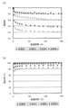
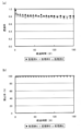
- FIG. 3 (a) shows the measurement results of transmittance, showing the effect of baffle installation and vibration flow when a humic acid aqueous solution is subjected to membrane separation treatment using a hollow fiber membrane with a molecular weight cut off of 30,000.
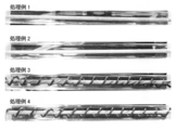
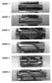
- FIG. 3B shows the measurement result of the rejection rate. It is an experimental result showing the effect by baffle installation and vibration flow when a humic acid aqueous solution is subjected to membrane separation treatment using a hollow fiber membrane having a molecular weight cut off of 30,000, and shows a photograph of the membrane appearance after the treatment.
- FIG. 3 (a) shows the measurement results of transmittance, showing the effect of baffle installation and vibration flow when a humic acid aqueous solution is subjected to membrane separation treatment using a hollow fiber membrane with a molecular weight cut off of 30,000.
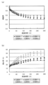
- FIG. 5 (a) shows the measurement results of transmittance, showing the effect of baffle installation and vibration flow when a humic acid aqueous solution is subjected to membrane separation treatment using a hollow fiber membrane having a molecular weight cut off of 150,000.
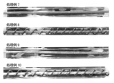
- FIG. 5B shows the measurement result of the rejection rate. It is an experimental result showing the effect by baffle installation and an oscillating flow at the time of carrying out the membrane separation process of the humic acid aqueous solution using the hollow fiber membrane of 150,000 molecular weight cut off, and represents the film
- FIG. 7 (a) shows the measurement results of transmittance, in which the generation conditions of the oscillating flow when the humic acid aqueous solution was subjected to membrane separation treatment using a hollow fiber membrane having a molecular weight cut off of 30,000 was changed.
- FIG. 7B shows the measurement result of the rejection rate.
- FIG. 8 (a) shows the measurement results of transmittance, in which the generation conditions of the oscillating flow when the humic acid aqueous solution was subjected to membrane separation treatment using a hollow fiber membrane with a molecular weight cut off of 150,000 was changed.
- FIG. 8B shows the measurement result of the rejection rate.
- the system flow figure of the experimental apparatus used in Experiment 2 of an Example is represented.
- FIG. 10A is an experimental result showing the effect of baffle placement and vibration flow when a humic acid aqueous solution is subjected to membrane separation treatment using a hollow fiber membrane bundle having a molecular weight cut off of 150,000
- FIG. 10B shows the measurement result of the rejection rate. It is an experimental result showing the effect by baffle installation and an oscillating flow at the time of carrying out membrane separation processing of humic acid aqueous solution using a hollow fiber membrane bundle of 150,000 molecular weight cuts, and shows the membrane appearance photograph after processing.
- FIG. 10A is an experimental result showing the effect of baffle placement and vibration flow when a humic acid aqueous solution is subjected to membrane separation treatment using a hollow fiber membrane bundle having a molecular weight cut off of 150,000
- FIG. 10B shows the measurement result of the rejection rate.
- FIG. 12A is an experimental result showing the effect of changing the straw hull number when a humic acid aqueous solution is subjected to membrane separation treatment using a hollow fiber membrane bundle having a molecular weight cut off of 150,000, and FIG. FIG. 12B shows the relationship between the Strouhal number and the rejection rate.
- the present invention relates to a method for subjecting water to be treated to membrane separation using a membrane module provided with a tubular separation membrane.
- separation membranes used in the present invention include microfiltration membranes (MF membranes), ultrafiltration membranes (UF membranes), reverse osmosis membranes (RO membranes), etc.
- MF membranes microfiltration membranes
- UF membranes ultrafiltration membranes
- RO membranes reverse osmosis membranes
- the membrane separation treatment method of the present invention includes, for example, wastewater (for example, sewage, human waste, livestock manure, kitchen wastewater, factory wastewater, landfill leachate, process wastewater in those treatments) treatment, water purification treatment, separation / concentration in a manufacturing process. It can be applied to separation and recovery of useful substances, seawater desalination and the like.
- the membrane module used in the present invention will be described.
- the membrane module used in the present invention is configured by accommodating a tubular separation membrane in a casing.
- the separation membrane is tubular, and the tube axis direction is preferably formed longer than the vertical direction.
- the water to be treated is supplied from the outside of the separation membrane, and the water to be treated is moved from the outside to the inside of the separation membrane by pressurizing the outside of the separation membrane and / or depressurizing the inside of the separation membrane. Permeate to obtain membrane treated water.
- tubular separation membrane a known separation membrane can be used, and typically a hollow fiber membrane can be used.
- a single hollow fiber membrane may be used, or a hollow fiber membrane bundle in which a plurality of hollow fiber membranes are bundled.
- the hollow fiber membrane is used as a hollow fiber membrane bundle.
- a tubular type separation membrane may also be used as the tubular separation membrane, and organic membranes and inorganic membranes (ceramic membranes) are known as the tubular type separation membrane.
- the housing accommodates the tubular separation membrane inside.
- a housing casing
- casing is not specifically limited, It is preferable that it is a cylinder shape extended in the pipe-axis direction of a tubular separation membrane.
- the cylindrical shape is not limited to a circular cross section, and may be an elliptical shape, a polygonal shape, or an indefinite shape.
- the casing is preferably cylindrical, and in this case, it is preferable that the axial direction of the cylindrical shape substantially coincides with the tube axis direction of the tubular separation membrane.
- the housing is provided with a first opening on one side in the tube axis direction of the tubular separation membrane and a second opening on the other side outside the tubular separation membrane.
- the first opening and the second opening are provided in order to allow the treated water to enter and exit from the housing.
- the water to be treated is introduced into the housing through the first opening, and the water to be treated which has not permeated the tubular separation membrane by the membrane separation treatment is discharged from the housing through the second opening as concentrated water.
- the water to be treated is introduced into the membrane module through the first opening as a whole, subjected to membrane separation treatment, and then discharged from the membrane module through the second opening.
- a part of the water to be treated introduced into the membrane module may have a time period for flowing out of the housing through the first opening, and the concentrated water flowing out of the housing through the second opening. There may be a time period during which a part is returned to the housing again through the second opening.
- a baffle is provided outside the tubular separation membrane, and a flow path extending across the baffle in the tube axis direction is formed.
- the baffle is provided so as to be perpendicular or inclined with respect to the tube axis direction of the tubular separation membrane. By providing the baffle in this way, a vortex is easily generated in the vicinity of the surface of the separation membrane.
- the baffle is preferably provided at an angle of 45 ° to 90 ° (more preferably 60 ° to 90 °) with respect to the tube axis direction.
- a flow path extending across the baffle in the tube axis direction is formed in the housing.
- the flow path is provided so that the water to be treated introduced into the casing flows along the tube axis direction.
- the flow path of the water to be treated is provided with a baffle separated from the tubular separation membrane or a baffle. May be formed apart from the inner surface of the housing, or by providing a hole in the baffle.
- the tubular separation membrane is a hollow fiber membrane bundle
- the hollow fiber membrane is loosely fixed in the casing to some extent, and a flow path of water to be treated can be formed between the hollow fiber membranes.
- the shape of the baffle is not particularly limited, and may be provided so as to partially block the flow of the water to be treated in the tube axis direction.
- the baffle is provided in a plate shape, for example, and may be provided so that the baffle surrounds the separation membrane as viewed from the tube axis direction.
- the baffle does not necessarily have to have a flat surface facing the water to be treated, but may have a curved surface.
- the baffle is provided so as to hit the baffle a plurality of times when the water to be treated flows in the tube axis direction.
- the baffle is preferably provided so as to surround the tubular separation membrane spirally.
- the baffle is provided in a spiral shape with the tubular separation membrane as an axis.
- a plurality of baffles are formed in a flat plate shape, and a tubular separation membrane is provided through the plurality of baffles.
- the pitch of the baffles that is, the pitch (interval) of the baffles and the pitch between the baffles (baffle interval) are circular in the vertical cross section of the casing in the tube axis direction It is preferably 0.5 times or more of the equivalent diameter, more preferably 0.8 times or more, further preferably 1.0 times or more, more preferably 5.0 times or less, and even more preferably 4.0 times or less, 3.0 times or less is more preferable.
- the equivalent circle diameter of the vertical cross section in the tube axis direction of the casing means the diameter of a circle having the same area as the vertical cross sectional area in the tube axis direction of the casing.
- the baffle is preferably provided in the widest possible range in the tube axis direction of the tubular separation membrane.
- the length of the baffle from the end closest to the first opening to the end closest to the second opening is 50% or more (more preferably 70%) of the length in the tube axis direction of the tubular separation membrane. %, More preferably 80% or more).
- three or more baffles are provided.
- the baffle is preferably provided so as to occupy an area of 20% or more and 90% or less of the portion excluding the separation membrane in the housing when the membrane module is viewed from the tube axis direction. That is, the baffle is preferably provided such that the projected area in the tube axis direction is 20% or more and 90% or less of the projected area in the tube axis direction of the portion excluding the separation membrane in the housing.
- the area is more preferably 40% or more, still more preferably 50% or more, and preferably 80% or less.
- the baffle is preferably provided separately from the tubular separation membrane. If the baffle is provided in this way, when the water to be treated is introduced into the housing and flows from the first opening side to the second opening side, the water to be treated easily flows in the vicinity of the surface of the tubular separation membrane. The eddy current is easily generated in the vicinity of the surface. As a result, the surface of the separation membrane is easily cleaned, and the water permeability (membrane flux) and separation performance of the membrane are easily improved.
- the baffle When the baffle is provided away from the tubular separation membrane, at least a part of the baffle may be provided away from the tubular separation membrane.
- the tubular separation membrane can be fixed by the baffle, and the separation membrane can be stably installed in the housing.
- the entire baffle may be provided away from the tubular separation membrane. In this case, the effective membrane area can be increased.
- the separation distance ensures a desired flow rate of the water to be treated flowing in the vicinity of the surface of the tubular separation membrane, and a vortex is suitably generated in the vicinity of the surface of the tubular separation membrane.
- it is appropriately determined according to the scale of the membrane module or the separation membrane.
- the maximum separation distance between the tubular separation membrane and the baffle may be in the range of 0.1 mm to 50 mm, for example.
- the baffle may be provided separately from the inner surface of the casing or may be provided in contact with the inner surface of the casing. In addition, it is preferable that the baffle is provided in contact with the inner surface of the housing from the viewpoint of easily generating vortex near the surface of the separation membrane. Alternatively, if the baffle is provided away from the inner surface of the housing, the baffle is also provided away from the tubular separation membrane, and the separation distance between the baffle and the inner surface of the housing is greater than the separation distance between the baffle and the tubular separation membrane. It is preferable to shorten the length.
- the baffle may be provided with a hole other than the portion through which the tubular separation membrane penetrates.
- the flow rate of water to be treated flowing in the vicinity of the surface of the tubular separation membrane is ensured to a desired level, and is set appropriately in consideration of the point that vortex flow is suitably generated in the vicinity of the surface of the tubular separation membrane. It is preferable to do.
- the membrane module as described above is used to perform the membrane treatment by introducing the water to be treated into the housing from the first opening, and at this time, the flow rate in the first opening of the water to be treated is periodically changed.
- the membrane separation performance may be deteriorated by merely periodically changing the flow rate of the water to be treated without providing the baffle.
- the membrane separation performance may not be improved by simply flowing a fixed amount of water, the flow rate of water to be treated is periodically changed after providing a baffle as described above. It became clear that the processing performance was remarkably improved. That is, it became clear that the synergistic effect by the combination of both can be obtained by installing baffles and periodically changing the flow rate of the water to be treated.
- the flow rate and the flowing direction of the water to be treated in the housing are periodically changed while the water to be treated flows in the direction from the first opening to the second opening in the housing.
- vortices are periodically generated in the vicinity of the surface of the separation membrane, and the generated vortices periodically move on the surface of the separation membrane in the tube axis direction.
- the surface of the separation membrane is appropriately washed, and the water permeability (membrane permeation flux) and separation performance of the membrane are improved.
- the flow rate on the separation membrane surface can be periodically increased. As a result, the thickness of the concentration polarization layer on the separation membrane surface becomes thin, and the UF membrane From this point of view, improvement of membrane treatment performance can be expected for RO membranes and RO membranes.
- the water to be treated may always flow into the housing from the first opening, or the water to be treated flows out of the housing through the first opening. There may be a time zone to do. In the former case, the water to be treated always flows into the housing from the first opening, but the flow velocity changes periodically. In the latter case, the inflow and outflow of the water to be treated from the inside of the housing through the first opening changes periodically. In the present invention, it is preferable to change the flow rate of the water to be treated as in the latter case.
- the flow velocity at the first opening of the water to be treated takes a positive value when the water to be treated flows into the housing through the first opening, and is a negative value when the water to be treated flows out of the housing through the first opening. It is preferable to change so as to periodically take a positive value and a negative value.
- the water to be treated is introduced into the casing alternately from the first opening and the second opening, or the first opening is made using the water to be treated as an oscillating flow. Or a method of introducing it into the housing. Further, while introducing the water to be treated into the housing from the first opening, by moving the baffle in the tube axis direction or rotating the helical baffle (rotating around the tube axis of the tubular separation membrane), It is also possible to periodically change the flow velocity at the first opening of the water to be treated.
- the discharge amount of a pump that supplies the water to be treated into the casing from the first opening is changed periodically, or the pump and the first opening
- the vibration flow generator may be provided by connecting to a pipe connecting the pipes, and the water to be treated in the pipe may be periodically extracted and pushed out by the vibration flow generator.
- the water to be treated can be introduced into the housing from the first opening so that the flow rate of the water to be treated takes a positive value and a negative value, which is preferable. What is necessary is just to change periodically the flow velocity in the 1st opening of to-be-processed water with arbitrary waveforms, such as a sine wave and a triangular wave.
- the flow velocity at the first opening of the water to be treated is a relatively fast cycle. This makes it easy to constantly generate vortex near the surface of the separation membrane, and to improve the membrane treatment performance.
- the flow rate at the first opening of the water to be treated is a period of 0.01 seconds to 300 seconds (the period is more preferably 0.05 seconds or more, more preferably 0.1 seconds or more, and more preferably 60 seconds or less. 30 seconds or less is more preferable, and 15 seconds or less is particularly preferable.
- it is preferable to change so that the flow velocity in the 1st opening of to-be-processed water may take a positive value and a negative value with the said period.
- the frequency is the reciprocal of the period.
- the pushing volume of the vibration flow generator (that is, the state in which the water to be treated is most drawn out by the vibration flow generator is the highest). It is preferable to relatively increase the volume of water to be treated that is supplied when the state is shifted to the extruded state. Thereby, it becomes easy to generate a vortex in the housing, and it becomes easy to improve the membrane processing performance.
- the stroke length for pushing and pulling the piston in the oscillating flow generator may be increased.
- the membrane separation treatment system shown in FIG. 1 includes a membrane module 14, a pump 11 that supplies the treated water 1 into the membrane module 14, a supply line 12 that connects the pump 11 and the membrane module 14, and a supply line 12. And an oscillating flow generator 13 provided in connection therewith.
- the membrane module 14 accommodates the tubular separation membrane 15 and the tubular separation membrane 15, and the first opening 17 and the second opening on the one side and the other side of the tubular separation membrane 15 on the outer side of the tubular separation membrane 15.
- a baffle 19 provided on the outside of the tubular separation membrane 15 so as to be perpendicular or inclined with respect to the tube axis direction of the tubular separation membrane 15.
- the baffle 19 is provided apart from the tubular separation membrane 15, thereby forming a flow path extending across the baffle 19 in the tube axis direction.
- a baffle 19 is provided to be joined to the inner surface of the housing 16.
- the flow path extending across the baffle 19 in the tube axis direction is not limited to the mode shown in FIG. 1 and may be formed by providing the baffle 19 apart from the inner surface of the housing 16. It may be formed by providing a hole.
- the tubular separation membrane 15 is a hollow fiber membrane bundle, it may be formed between the hollow fiber membranes.
- the baffle 19 is provided spirally so as to surround the tubular separation membrane 15 so as to be inclined in the tube axis direction of the tubular separation membrane 15, but the baffle installation mode is not limited to this.
- a flat baffle may be provided so as to be perpendicular or inclined with respect to the tube axis direction.
- the baffle 19 is preferably provided at an angle of 45 ° to 90 ° with respect to the tube axis direction.
- the pump 11 is provided for supplying the water to be treated 1 to the casing 16, and the type thereof is not particularly limited.
- the treated water 1 is preferably supplied quantitatively from the pump 11.
- the supply pipe 12 is provided in communication with the pump 11 and the first opening 17, and the treated water 1 supplied (discharged) from the pump 11 circulates therethrough.
- the oscillating flow generator 13 is provided in connection with the supply pipe 12 and operates so as to periodically draw out and push out the treated water 1 in the supply pipe 12.
- the water 1 to be treated in the supply pipe 12 is periodically drawn out and pushed out by a piston.
- the to-be-processed water 1 will be supplied in the housing
- the treated water 1 is introduced into the housing 16 through the first opening 17 by the pump 11, and at that time, the flow velocity of the treated water 1 in the first opening 17 is periodically changed by the vibration flow generator 13. At this time, it is preferable that the inflow and outflow of the treated water 1 into the housing 16 are periodically repeated by the vibration flow generator 13. That is, when the treated water 1 flows into the housing 16 through the first opening 17, the flow rate of the treated water 1 in the first opening 17 takes a positive value, and the treated water 1 passes through the first opening 17. When the flow rate in the first opening 17 of the water to be treated 1 takes a negative value when flowing out of the water 16, the flow rate in the first opening 17 of the water to be treated 1 periodically takes a positive value and a negative value. It is preferable to change to.
- the flow rate of the water 1 to be treated 1 in the first opening 17 is increased by increasing the internal volume of the piston or shortening the frequency of pushing and pulling the piston (increasing the frequency). Can be periodically changed to take a positive value and a negative value (however, the pump supply amount is constant).
- the treated water 1 introduced into the membrane module 14 is subjected to a membrane separation treatment, whereby the treated water 1 permeates from the outside to the inside of the separation membrane 15 to obtain the membrane treated water 2.
- the treated water 1 that has not passed through the separation membrane 15 is discharged from the second opening 18 as the concentrated water 3.
- the second opening 18 is preferably connected to a discharge pipe 20 for discharging the concentrated water 3.
- the discharge pipe 20 is preferably provided so that the back pressure of the membrane module 14 is secured.
- a back pressure valve is provided in the discharge pipe 20
- a pressure gauge is provided in the discharge pipe 20
- the supply pipe 12 or the housing 16 and a valve is provided in the discharge pipe 20.
- the opening of the valve may be appropriately operated according to the value of the pressure gauge.
- the discharge pipe 20 when the discharge pipe 20 is installed so that the surface of the concentrated water 3 in the discharge pipe 20 is higher than the second opening 18, the concentrated water 3 in the discharge pipe 20 is discharged. It is preferable that the air is released to the atmosphere at the highest point of the pipeline 20.
- the housing 16 By installing the discharge pipe 20 in this way, even when the water to be treated flows out of the housing 16 through the first opening 17 due to the oscillating flow, the housing 16 can be filled with the water to be treated or concentrated water. And membrane separation treatment can be suitably performed.
- the volume from the second opening 18 of the discharge pipe 20 to the highest point of the discharge pipe 20 that is, the capacity from the second opening 18 of the concentrated water 3 in the discharge pipe 20 to the highest point of the discharge pipe 20).
- the discharge pipe 20 From the pushing volume of the oscillating flow generator 13 (that is, the volume of the effluent 1 supplied when the oscillating flow generator 13 makes a transition from the most extracted state to the most extruded state). It is preferable to provide the discharge pipe 20 so as to be larger. Further, as described above, when a valve is provided in the discharge pipe 20 to ensure the back pressure of the membrane module 14, the volume of the discharge pipe 20 is set to be larger than the pushing volume of the oscillating flow generator 13. It is preferable to provide the discharge pipe 20 or provide an air valve in the discharge pipe 20.
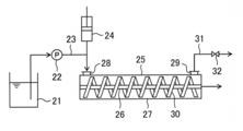
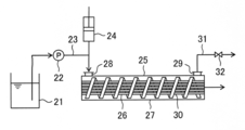
- the test apparatus mainly includes a membrane module 25, a pump 22 that supplies water to be treated to the membrane module 25, and a vibration flow generator 24 provided between the pump 22 and the membrane module 25.
- the membrane module 25 is a hollow fiber membrane made of polyethersulfone (manufactured by Daisen Membrane Systems Co., Ltd., ultrafiltration membrane, 1 mm in diameter, long in a cylindrical housing 27 having an inner diameter of 4 mm and a length of 110 mm.
- a wire having a diameter of about 1 mm was installed in a spiral shape (a spiral pitch of about 6 mm) as a baffle 30 surrounding the tubular separation membrane 26.
- the baffle 30 (wire) is provided apart from the surface of the tubular separation membrane 26 and is also provided partly away from the inner surface of the housing 27.
- the baffle 30 (wire) occupied about 3/4 of the area excluding the hollow fiber membrane in the cross section in the cylindrical housing.
- the cylindrical housing 27 is provided with a first opening 28 and a second opening 29 on one side and the other side in the axial direction (corresponding to the tube axis direction of the tubular separation membrane in FIG. 2).
- a supply tube 23 made of PFA (tetrafluoroethylene / perfluoroalkyl vinyl ether copolymer) (manufactured by Saint-Gobain Co., Ltd., Tygon (registered trademark) tube 6409-16, inner diameter 3. 2 mm, outer diameter 6.4 mm) and a tubing pump 22 (manufactured by Cole-Parmer, Masterflex (registered trademark) L / S tubing pump 07528-30) is provided in the supply tube 23.
- the treated water can be supplied into the housing 27 through the first opening 28.
- a syringe drive module (manufactured by Hamilton, PSD / 8 short drive system) is used, and a PTFE syringe (manufactured by Hamilton, 1010TLL, capacity 10 mL, cross-sectional area 1.67 cm 2 ) is used for the module.
- a syringe drive module manufactured by Hamilton, PSD / 8 short drive system
- a PTFE syringe manufactured by Hamilton, 1010TLL, capacity 10 mL, cross-sectional area 1.67 cm 2
- the syringe is configured such that the plunger (inner cylinder) is automatically pushed and pulled by the syringe drive module, and the water to be treated is drawn into the syringe from the supply tube 23 and the water to be treated drawn into the syringe.
- the treated water was supplied from the first opening 28 into the housing 27 as a triangular wave vibration flow from the syringe drive module.
- the water to be treated supplied into the casing 27 is pressurized to 50 kPa (gauge pressure) in the casing 27 (corresponding to the transmembrane pressure difference) and permeates inside the tubular separation membrane 26 (hollow fiber membrane). However, it has come to be obtained as membrane treated water.
- the treated water that has not permeated through the tubular separation membrane 26 is discharged from the housing 27 through the second opening 29 as concentrated water, and the second opening 29 has a discharge tube 31 (same as the supply tube). Specification) was connected, and a valve 32 was attached to the discharge tube 31 in order to maintain the pressurized state in the housing 27.
- the membrane separation treatment was performed by removing the baffle (wire) in the above test apparatus.
- Membrane separation treatment was performed using an aqueous humic acid solution as water to be treated.
- the humic acid aqueous solution was prepared by adding humic acid sodium salt (manufactured by Sigma-Aldrich) to a 1 mM NaHCO 3 aqueous solution little by little and adjusting the concentration to 50 mg / L.
- the pH of the prepared aqueous humic acid solution was 8.4.
- the water to be treated is supplied into the housing 27 at an average flow rate of 16.6 mL / min (0.277 mL / sec) with the tubing pump 22 through the supply tube 23, and at that time, the plunger of the syringe is pushed and pulled.
- the aqueous humic acid solution was subjected to a membrane separation treatment for 180 minutes, and the permeability and blocking rate were measured as membrane treatment performance.
- two types of hollow fiber membrane A having a molecular weight cut off of 30,000 and hollow fiber membrane B having a molecular weight cut off of 150,000 were used.
- the membrane treatment performance was examined by varying the presence or absence of vibration and the generation conditions of the oscillating flow.
- the stroke length and frequency represent the stroke length and frequency for pushing and pulling the plunger, respectively
- the maximum flow rate and the minimum flow rate represent the maximum value and the minimum value of the flow rate of the water to be treated passing through the first opening, respectively. It is proportional to the flow rate of the water to be treated that passes through the first opening. Note that the maximum flow rate and the minimum flow rate are expressed as positive values when the water to be treated flows into the casing, and expressed as negative values when flowing out of the casing. When no oscillating flow is generated, the water to be treated flows into the housing at a constant speed, and the maximum flow rate and the minimum flow rate do not change.
- FIGS. 3 to 6 show the results of examining the effect of installing a baffle and generating an oscillating flow.
- 3 and 4 show the processing results of the processing examples 1 to 4
- FIGS. 5 and 6 show the processing results of the processing examples 7 to 10.
- 3 (a) and 5 (a) show the transmittance results
- FIG. 3 (b) and FIG. 5 (b) show the rejection results
- FIGS. 4 and 6 are photographs of the film appearance after processing. Represents.
- the appearance of the hollow fiber membrane after the treatment also resulted in greatly reducing the adhesion of dirt on the membrane surface by combining the baffle and the vibration flow. From this result, it is considered that by combining the baffle and the oscillating flow, the concentration polarization on the film surface is suppressed and the humic acid concentration in the vicinity of the film surface is lowered.
- the transmittance and the blocking rate are contradictory and it is difficult to improve both at the same time. The improvement of both is a very remarkable result.
- FIG. 7 and 8 show the results when the generation conditions of the oscillating flow are changed.
- FIG. 7 shows the results of Processing Examples 4 to 6
- FIG. 8 shows the results of Processing Examples 10 to 16.
- 7A and 8A show the transmittance results
- FIGS. 7B and 8B show the rejection results.
- the transmittance and the rejection were hardly changed.
- the transmittance and the rejection rate tended to improve. This is because by increasing the stroke length and increasing the frequency, the maximum flow velocity of the oscillating flow increases, or the negative absolute value of the minimum flow velocity increases, resulting in a stronger vortex near the surface of the hollow fiber membrane. This is thought to be easier.
- Experiment 2 Membrane separation treatment experiment using hollow fiber membrane bundle (2-1) Test apparatus Membrane separation treatment was performed using the test apparatus shown in FIG.
- the test apparatus shown in FIG. 9 has substantially the same apparatus configuration as the test apparatus shown in FIG. 2, and the same components are denoted by the same reference numerals.
- a polyethersulfone hollow fiber membrane (Daisen Membrane Systems Co., Ltd., ultrafiltration membrane, diameter 0.95 mm, length 50 mm, fractional molecular weight) 150,000) 30 hollow fiber bundles (effective membrane area: 4.48 ⁇ 10 ⁇ 3 m 2 ) are used. Therefore, each component is scaled up as a whole.
- a cylindrical housing with a diameter of 16 mm and a length of 50 mm is used as the housing 27, and a wire with a diameter of about 2.8 mm is used for the baffle 30.
- the hollow fiber membrane bundle was installed in a spiral shape (spiral pitch of about 14 mm or about 28 mm).
- the transmembrane pressure difference was maintained at 50 kPa (gauge pressure) as in Experiment 1.
- the baffle 30 is provided partially apart from the tubular separation membrane 26, a flow path of water to be treated is formed between the baffle 30 and the tubular separation membrane 26, and the hollow that forms the tubular separation membrane 26 is formed.
- a flow path of water to be treated was also formed between the yarn membranes.
- Strouhal number v ⁇ f / u v: Vibration volume (mL) f: Frequency (s ⁇ 1 ) u: Average flow rate (mL / s)
- FIGS. 10 and 11 show the processing results of the processing examples 17-22.
- FIG. 10A shows the result of transmittance
- FIG. 10B shows the result of blocking rate
- FIG. 11 shows the film appearance photograph after processing.
- the appearance of the hollow fiber membrane after the treatment was also reduced by attaching dirt on the membrane surface by combining the baffle and the vibration flow.
- FIG. 12 shows the result of examining the relationship between the Strouhal number and the membrane permeation flux or the rejection rate by performing various changes in frequency and vibration volume.
- FIG. 12A shows the relationship between the straw hull number and the membrane permeation flux
- FIG. 12B shows the relationship between the straw hull number and the blocking rate.
- the present invention can be applied to waste water treatment, water purification treatment, separation / concentration treatment in a manufacturing process, separation and collection of useful substances, and the like.
Landscapes
- Chemical & Material Sciences (AREA)
- Chemical Kinetics & Catalysis (AREA)
- Engineering & Computer Science (AREA)
- Water Supply & Treatment (AREA)
- Nanotechnology (AREA)
- Life Sciences & Earth Sciences (AREA)
- Hydrology & Water Resources (AREA)
- Environmental & Geological Engineering (AREA)
- Organic Chemistry (AREA)
- Separation Using Semi-Permeable Membranes (AREA)
Abstract
管状分離膜(15)が筐体(16)内に収容された膜モジュール(14)を用いて被処理水(1)を膜分離処理する方法であって、筐体(16)には、管状分離膜(15)の外側に、管状分離膜(15)の管軸方向の一方側と他方側に第1開口(17)と第2開口(18)が設けられ、管状分離膜(15)の外側に管軸方向に垂直または傾斜するようにバッフル(19)が設けられ、バッフル(19)を管軸方向に横切って延びる流路が形成され、被処理水(1)を第1開口(17)から筐体(16)内に導入し、被処理水(1)の第1開口(17)における流速を周期的に変化させる。
Description
本発明は、分離膜を用いた水処理方法およびそのシステムに関するものである。
分離膜を用いた水処理技術は、現在様々な分野で用いられている。水処理に用いられる分離膜は、その孔径によって、精密ろ過膜(MF膜)、限外ろ過膜(UF膜)、逆浸透膜(RO膜)等に分類され、例えば、浄水処理では固液分離のためにMF膜を用いた処理が行われたり、下水処理やし尿処理では高濃度の活性汚泥処理と固液分離を兼ねたMF膜を用いた処理が行われたりしている。また、細菌やウィルスの除去や工業分野におけるタンパク質等の除去または濃縮にUF膜が用いられたり、海水淡水化や超純水製造ではRO膜を用いた処理が行われたりしている。
ところで膜分離処理では、膜分離性能を確保しつつ膜の透水量(膜透過流束)をできるだけ高めるようにすることが求められる。膜分離性能(公称孔径や分子量分画)は、用いる分離膜の仕様に応じて基本的に定められるが、処理を継続しても、あるいは処理の初期段階から、所望する膜分離性能が発揮されるようにすることが好ましく、その上で膜の透水量をできるだけ高めて、処理システムのコンパクト化を図るようにすることが望まれる。例えば膜透過流束を高める試みとして、特許文献1には、膜モジュールの両端に設けられた供給口から被処理水を交互に切り替えて供給することにより、膜透過流束を長期にわたって高く維持できたことが開示されている。
上記のように、膜処理性能を高めることについては従来様々な試みが行われてきており、膜分離処理においては根源的な要望といえる。本発明はそのような事情に鑑みてなされたものであり、その目的は、管状分離膜を備えた膜モジュールを用いて膜分離処理する際に、膜の透水量(膜透過流束)と分離性能を高めることができる膜分離処理方法および膜分離処理システムを提供することにある。
前記課題を解決することができた本発明の膜分離処理方法とは、管状分離膜が筐体内に収容された膜モジュールを用いて被処理水を膜分離処理する方法であって、筐体には、管状分離膜の外側に、管状分離膜の管軸方向の一方側と他方側に第1開口と第2開口が設けられ、管状分離膜の外側に、管軸方向に垂直または傾斜するようにバッフルが設けられ、バッフルを管軸方向に横切って延びる流路が形成され、被処理水を第1開口から筐体内に導入し、被処理水の第1開口における流速を周期的に変化させるところに特徴を有する。本発明の膜分離処理方法によれば、被処理水が筐体内に導入されて、第1開口側から第2開口側に管軸方向に延びる流路に沿って流れる際に、被処理水がバッフルに当たることにより分離膜の表面近傍で渦流が発生して、分離膜の表面が適度に洗浄されると考えられる。その結果、膜の透水量(膜透過流束)と分離性能を向上させることができる。
前記流路は、バッフルが管状分離膜から離間して設けられることにより形成されていることが好ましい。このようにバッフルが設けられれば、被処理水が管状分離膜の表面近傍を流れやすくなり、分離膜の表面近傍で渦流が好適に発生しやすくなる。その結果、分離膜の表面が洗浄されやすくなり、膜の透水量(膜透過流束)と分離性能が向上しやすくなる。
本発明の膜分離処理方法では、被処理水が第1開口を通じて筐体内へ流入する場合に前記流速が正値をとり、被処理水が第1開口を通じて筐体内から流出する場合に前記流速が負値をとるとしたとき、前記流速を周期的に正値と負値をとるように変化させることが好ましい。また前記流速を、0.01秒以上30秒以下の周期で変化させることが好ましい。このように被処理水を導入することにより、膜の透水量(膜透過流束)と分離性能をさらに向上させることができる。管状分離膜としては、中空糸膜やその束を用いることができる。
本発明はまた、管状分離膜と;管状分離膜を収容し、管状分離膜の外側に、管状分離膜の管軸方向の一方側と他方側に第1開口と第2開口が設けられた筐体と;管状分離膜の外側に、管軸方向に垂直または傾斜するように設けられたバッフルと;バッフルを管軸方向に横切って延びる流路と;筐体内に被処理水を供給するポンプと;ポンプと第1開口とに連通して設けられ、被処理水が流通する供給管路と;供給管路に接続して設けられ、供給管路内の被処理水を周期的に引き抜きと押し出しを繰り返す振動流発生装置とを有することを特徴とする膜分離処理システムを提供する。本発明の膜分離処理システムによれば、本発明の膜分離処理方法を好適に行うことができる。本発明の膜分離処理システムでは、バッフルが、管状分離膜から離間して設けられることにより、前記流路が形成されていることが好ましい。また、バッフルを、管状分離膜の管軸方向に対して45°以上90°以下の角度で設けることが好ましい。管状分離膜としては、中空糸膜やその束を用いることが好ましい。
本発明の膜分離処理方法および膜分離処理システムによれば、膜モジュール内にバッフルを設置して、バッフルを管軸方向に横切って延びる流路を形成し、膜モジュール内に導入する被処理水の流速を周期的に変化させることにより、膜の透水量と分離性能を向上させることができる。
本発明は、管状分離膜が備えられた膜モジュールを用いて、被処理水を膜分離処理する方法に関するものである。本発明で用いられる分離膜としては、精密ろ過膜(MF膜)、限外ろ過膜(UF膜)、逆浸透膜(RO膜)等が挙げられ、被処理水はそれぞれの分離膜の処理対象として公知なものを用いることができる。本発明の膜分離処理方法は、例えば、廃水(例えば、下水、し尿、畜産糞尿、厨房排水、工場排水、埋立浸出水、それらの処理におけるプロセス排水)処理、浄水処理、製造プロセスにおける分離・濃縮、有用物質の分離回収、海水淡水化等に適用することができる。
本発明で用いる膜モジュールについて説明する。本発明で用いられる膜モジュールは、管状分離膜が筐体内に収容されて構成される。分離膜は管状であり、管軸方向がその垂直方向よりも長く形成されることが好ましい。被処理水は分離膜の外側から供給され、分離膜の外側が加圧されることにより、および/または、分離膜の内側が減圧されることにより、被処理水が分離膜の外側から内側に透過し、膜処理水が得られる。
管状分離膜としては公知の分離膜を用いることができ、代表的には中空糸膜を用いることができる。中空糸膜は1本のみで用いてもよく、中空糸膜が複数本束ねられた中空糸膜束として用いてもよい。なお、一般的には中空糸膜は中空糸膜束として用いられる。管状分離膜としてはまた、チューブラー型の分離膜を用いてもよく、チューブラー型の分離膜としては有機膜や無機膜(セラミック膜)が知られている。
筐体は管状分離膜を内部に収容する。筐体の形状は特に限定されないが、管状分離膜の管軸方向に延びる筒形状であることが好ましい。筒形状は、断面が円形に限らず楕円形や多角形、不定形であってもよい。なお筐体は円筒形状が好ましく、この場合、円筒形状の軸方向と管状分離膜の管軸方向が実質的に一致することが好ましい。
筐体には、管状分離膜の外側に、管状分離膜の管軸方向の一方側に第1開口が設けられ、他方側に第2開口が設けられる。第1開口と第2開口は筐体内に被処理水が出入りするために設けられる。被処理水は、第1開口を通じて筐体内に導入され、膜分離処理により管状分離膜を透過しなかった被処理水が濃縮水として第2開口を通じて筐体内から排出される。
被処理水は、全体として、第1開口を通じて膜モジュールに導入され、膜分離処理が施された後、第2開口を通じて膜モジュールから排出される。なお、後述するように、膜モジュールに導入された被処理水の一部は第1開口を通じて筐体内から流出する時間帯があってもよく、また第2開口を通じて筐体内から流出した濃縮水の一部は第2開口を通じて再び筐体内に戻される時間帯があってもよい。
筐体内には、管状分離膜の外側にバッフルが設けられ、バッフルを管軸方向に横切って延びる流路が形成されている。被処理水は、筐体内に導入されて、第1開口側から第2開口側に管軸方向に延びる流路に沿って流れる際に、被処理水がバッフルに当たることにより渦流が発生して、分離膜の表面が適度に洗浄されることを狙いとして設けられる。本発明では、このように膜モジュール内で被処理水の流れを制御することにより、膜の透水量(膜透過流束)と分離性能の向上を図ることができる。
バッフルは、管状分離膜の管軸方向に垂直または傾斜するように設けられる。このようにバッフルを設けることにより、分離膜の表面近傍で渦流が発生しやすくなる。バッフルは、管軸方向に対して45°以上90°以下(より好ましくは60°以上90°以下)の角度で設けられることが好ましい。
筐体内には、バッフルを管軸方向に横切って延びる流路が形成されている。流路は、筐体内に導入された被処理水が管軸方向に沿って流れるために設けられるものであり、被処理水の流路は、バッフルを管状分離膜から離間して設けたり、バッフルを筐体内面から離間して設けたり、あるいはバッフルに穴を設けることにより形成されればよい。また、管状分離膜が中空糸膜束であるような場合には、中空糸膜がある程度ルーズに筐体内に固定され、中空糸膜どうしの間にも被処理水の流路が形成され得る。
バッフルの形状は特に限定されず、被処理水の管軸方向への流れを一部遮るように設けられればよい。バッフルは、例えば板状に設けられ、管軸方向から見て、バッフルが分離膜を取り囲むように設けられればよい。バッフルは、被処理水が当たる対向面が必ずしも平面状に形成されていなくてもよく、曲面状に形成されていてもよい。
バッフルは、被処理水が管軸方向に流れる場合に、バッフルに複数回当たるように、設けられることが好ましい。具体的には、バッフルは、管状分離膜を螺旋状に取り囲むように設けられることが好ましい。この場合、バッフルは、管状分離膜を軸にして、螺旋状に設けられることとなる。またバッフルは、平板状に形成されて複数設けられ、管状分離膜が複数のバッフルを貫通して設けられることも好ましい。これらのようにバッフルを設けることにより、管軸方向に沿って複数箇所で渦流が発生しやすくなり、膜の透水量と分離性能の向上を図りやすくなる。
上記のようにバッフルを螺旋状に設けたりバッフルを複数設ける場合、バッフルのピッチ、すなわち螺旋ピッチ(間隔)や複数のバッフル間のピッチ(バッフル間隔)は、筐体の管軸方向垂直断面の円相当直径の0.5倍以上とすることが好ましく、0.8倍以上がより好ましく、1.0倍以上がさらに好ましく、また5.0倍以下が好ましく、4.0倍以下がより好ましく、3.0倍以下がさらに好ましい。このようにバッフルを設けることにより、管状分離膜の表面で、管軸方向に対して広い範囲で、好適に渦流を発生させやすくなる。なお、筐体の管軸方向垂直断面の円相当直径とは、筐体の管軸方向垂直断面積と等面積の円の直径を意味する。
バッフルは、管状分離膜の管軸方向にできるだけ広い範囲で設けられることが好ましい。例えばバッフルは、最も第1開口部側にある端から最も第2開口部側にある端までの長さが、管状分離膜の管軸方向の長さに対して50%以上(より好ましくは70%以上であり、さらに好ましくは80%以上である)となるように設けられることが好ましい。なお前記態様において、バッフルが複数設けられる場合は、バッフルは3つ以上設けられることとする。このようにバッフルが設けられることにより、管状分離膜が管軸方向に対して広い範囲にわたって洗浄されやすくなる。
バッフルは、膜モジュールを管軸方向から見て、筐体内の分離膜を除く部分の20%以上90%以下の面積を占めるように設けられることが好ましい。すなわち、バッフルは、管軸方向の投影面積が、筐体内の分離膜を除いた部分の管軸方向の投影面積の20%以上90%以下となるように設けられることが好ましい。このようにバッフルを設けることにより、膜モジュールに導入する被処理水の水量を確保しつつ、分離膜の表面近傍で渦流を発生させやすくなる。前記面積(前記投影面積を含む)は、より好ましくは40%以上であり、さらに好ましくは50%以上であり、また80%以下が好ましい。
バッフルは管状分離膜から離間して設けられることが好ましい。このようにバッフルが設けられれば、被処理水が筐体内に導入されて第1開口側から第2開口側に流れる際に、被処理水が管状分離膜の表面近傍を流れやすくなり、分離膜の表面近傍で渦流が好適に発生しやすくなる。その結果、分離膜の表面が洗浄されやすくなり、膜の透水量(膜透過流束)と分離性能が向上しやすくなる。
バッフルが管状分離膜から離間して設けられる場合、バッフルは少なくとも一部が管状分離膜から離間して設けられればよい。例えば、バッフルの一部のみを管状分離膜から離間して設けることにより、管状分離膜をバッフルにより固定することができ、分離膜を筐体内に安定して設置することが可能となる。もちろん、バッフル全体を管状分離膜から離間して設けてもよく、この場合は、有効膜面積を高めることができる。
バッフルを管状分離膜から離間して設ける場合、その離間距離は、管状分離膜の表面近傍を流れる被処理水の流速を所望程度に確保し、管状分離膜の表面近傍で渦流が好適に発生するようにする点などを勘案して、膜モジュールや分離膜のスケールに応じて適宜定められる。実用上の膜モジュールを勘案すれば、管状分離膜とバッフルとの最大離間距離は、例えば0.1mm以上50mm以下の範囲にあればよい。
バッフルは、筐体内面に対しては離間して設けられてもよく、筐体内面に接して設けられてもよい。なお、分離膜の表面近傍で渦流が発生しやすくする点から、バッフルは、筐体内面に接して設けられることが好ましい。あるいは、バッフルが筐体内面から離間して設けられる場合は、バッフルは管状分離膜からも離間して設け、バッフルと筐体内面との離間距離が、バッフルと管状分離膜との離間距離よりも短くなるようにすることが好ましい。またバッフルには、管状分離膜が貫通する部分以外に、穴が設けられていてもよい。いずれの場合も、管状分離膜の表面近傍を流れる被処理水の流速を所望程度に確保し、管状分離膜の表面近傍で渦流が好適に発生するようにする点などを勘案して、適宜設定することが好ましい。
本発明では、上記に説明したような膜モジュールを用いて、被処理水を第1開口から筐体内に導入して膜処理を行い、この際に、被処理水の第1開口における流速を周期的に変化させるようにする。本発明者らが検討したところ、バッフルを設けずに被処理水の流速を周期的に変化させるだけでは、かえって膜分離性能が低下してしまう場合があったり、また、バッフルを設けて被処理水を一定量で流すだけではほとんど膜分離性能が向上しない場合があるにも関わらず、上記に説明したようにバッフルを設けた上で被処理水の流速を周期的に変化させることにより、膜処理性能が格段に向上することが明らかになった。すなわち、バッフルを設置して被処理水の流速を周期的に変化させることにより、両者の組み合わせによる相乗効果が得られることが明らかになった。
本発明においては、全体としては筐体内で被処理水を第1開口から第2開口の方向に流しつつ、筐体内での被処理水の流速や流れる方向を周期的に変化させる。このように被処理水を流すことにより、分離膜の表面近傍で周期的に渦が発生して、発生した渦が分離膜表面を管軸方向に周期的に移動するようになり、その結果、分離膜の表面が適度に洗浄され、膜の透水量(膜透過流束)と分離性能が向上するものと考えられる。また、被処理水の流速を周期的に変化させることにより、分離膜表面の流速を周期的に高めることができ、その結果、分離膜表面の濃度分極層の厚さが薄くなって、UF膜やRO膜においてはこの点からも膜処理性能の向上が期待できる。
被処理水の第1開口における流速を周期的に変化させる場合、被処理水は常に第1開口から筐体内に流入するようにしてもよいし、被処理水が第1開口を通じて筐体から流出する時間帯があってもよい。前者の場合、被処理水は常に第1開口から筐体内に流入するが、その流速が周期的に変化することとなる。後者の場合、被処理水は第1開口を通じた筐体内からの流入と流出が周期的に変化することとなる。本発明においては、後者のように被処理水の流速を変化させることが好ましい。すなわち、被処理水の第1開口における流速は、被処理水が第1開口を通じて筐体内へ流入する場合に正値をとり、被処理水が第1開口を通じて筐体内から流出する場合に負値をとるとしたとき、周期的に正値と負値をとるように変化することが好ましい。このように被処理水を流すことにより、バッフルの前後両方で周期的に渦が発生し、分離膜の表面が広範囲に適度に洗浄されたり、分離膜表面の流速を高めて、分離膜表面の濃度分極層の厚さを薄くすることができる。
被処理水の第1開口における流速を周期的に変化させる方法としては、被処理水を第1開口と第2開口から交互に筐体内に導入したり、被処理水を振動流として第1開口から筐体内に導入したりする方法が挙げられる。また、被処理水を第1開口から筐体内に導入しながら、バッフルを管軸方向に移動させたり、螺旋状のバッフルを回転させる(管状分離膜の管軸を中心に回転させる)ことにより、被処理水の第1開口における流速を周期的に変化させることも可能である。本発明では、被処理水の流速を周期的に変化させることが容易な点から、被処理水を振動流として第1開口から筐体内に導入したりする方法を採用することが好ましい。すなわち、被処理水の流速を周期的に変化させながら、被処理水を第1開口から筐体内に導入することが好ましい。
被処理水を振動流として第1開口から筐体内に導入するには、第1開口から筐体内に被処理水を供給するポンプの吐出量を周期的に変化させたり、当該ポンプと第1開口を繋ぐ管路に接続して振動流発生装置を設け、当該管路内の被処理水を振動流発生装置により周期的に引き抜きと押し出しを繰り返したりすればよい。特に振動流発生装置を設ける場合は、被処理水の流速が正値と負値をとるように被処理水を第1開口から筐体内に導入することができ、好ましい。被処理水の第1開口における流速は、サイン波や三角波等の任意の波形で周期的に変化させればよい。
本発明では、被処理水の第1開口における流速を比較的速い周期で変化させることが好ましく、これにより分離膜の表面近傍で絶えず渦流を発生させやすくなり、膜処理性能の向上が図りやすくなる。例えば、被処理水の第1開口における流速は0.01秒以上300秒以下の周期(当該周期は0.05秒以上がより好ましく、0.1秒以上がさらに好ましく、また60秒以下がより好ましく、30秒以下がさらに好ましく、15秒以下が特に好ましい)で変化させることが好ましい。さらに本発明では、被処理水の第1開口における流速が前記周期で正値と負値をとるように変化させることが好ましい。なお、周波数は周期の逆数となる。
また本発明では、被処理水を振動流発生装置により周期的に引き抜きと押し出しを繰り返す場合には、振動流発生装置の押し出し容積(すなわち振動流発生装置によって被処理水を最も引き抜いた状態から最も押し出した状態に移行させた場合に供給される被処理水の容量)を比較的大きくすることが好ましい。これにより筐体内で渦流を発生させやすくなり、膜処理性能の向上を図りやすくなる。振動流発生装置の押し出し容積を大きくするには、例えば、振動流発生装置におけるピストンを押し引きするストローク長を長くすればよい。
次に、本発明の膜分離処理方法と膜分離処理システムの構成例について、図1を参照して説明する。なお本発明は、図1に示した実施態様に限定されるものではない。
図1に示した膜分離処理システムは、膜モジュール14と、膜モジュール14内に被処理水1を供給するポンプ11と、ポンプ11と膜モジュール14を繋ぐ供給管路12と、供給管路12に接続して設けられた振動流発生装置13とを有する。膜モジュール14は、管状分離膜15と、管状分離膜15を収容し、管状分離膜15の外側に、管状分離膜15の管軸方向の一方側と他方側に第1開口17と第2開口18が設けられた筐体16と、管状分離膜15の外側に、管状分離膜15の管軸方向に垂直または傾斜するように設けられたバッフル19とを有する。
図1では、バッフル19が管状分離膜15から離間して設けられており、それにより、バッフル19を管軸方向に横切って延びる流路が形成されている。また図1では、バッフル19が筐体16の内面に接合して設けられている。なお、バッフル19を管軸方向に横切って延びる流路は、図1に示す態様に限らず、バッフル19が筐体16の内面から離間して設けられることにより形成されてもよく、バッフル19に穴が設けられることにより形成されてもよく、管状分離膜15が中空糸膜束であるような場合は、中空糸膜どうしの間に形成されてもよい。
図1では、バッフル19は、管状分離膜15の管軸方向に傾斜するように、管状分離膜15を取り囲んで螺旋状に設けられているが、バッフルの設置態様はこれに限定されない。例えば上記に説明したように、平板状のバッフルが管軸方向に垂直または傾斜するように設けられてもよい。バッフル19は、管軸方向に対して45°以上90°以下の角度で設けられることが好ましい。
ポンプ11は、筐体16に被処理水1を供給するために設けられ、特にその種類は限定されない。図1に示すように振動流発生装置13が設けられる場合は、ポンプ11からは定量的に被処理水1が供給されることが好ましい。供給管路12はポンプ11と第1開口17とに連通して設けられ、ポンプ11から供給(吐出)された被処理水1が流通する。
振動流発生装置13は供給管路12に接続して設けられ、供給管路12内の被処理水1を周期的に引き抜きと押し出しを繰り返すように作動する。図1に示した振動流発生装置13では、ピストンによって供給管路12内の被処理水1を周期的に引き抜きと押し出しを繰り返すように構成されている。振動流発生装置13により、被処理水1が振動流として筐体16内に供給されることとなる。
被処理水1は、ポンプ11によって第1開口17を通じて筐体16内に導入され、その際に振動流発生装置13によって被処理水1の第1開口17における流速を周期的に変化させる。このとき、振動流発生装置13によって、被処理水1の筐体16内への流入と流出が周期的に繰り返されることが好ましい。すなわち、被処理水1が第1開口17を通じて筐体16内へ流入する場合に被処理水1の第1開口17における流速が正値をとり、被処理水1が第1開口17を通じて筐体16内から流出する場合に被処理水1の第1開口17における流速が負値をとるとしたとき、被処理水1の第1開口17における流速が周期的に正値と負値をとるように変化することが好ましい。例えば、図1に示す振動流発生装置13では、ピストンの内容積を大きくしたり、ピストンを押し引きする周期を短く(周波数を高く)することにより、被処理水1の第1開口17における流速を周期的に正値と負値をとるように変化させることができる(ただし、ポンプ供給量は一定とする)。
膜モジュール14内に導入された被処理水1は膜分離処理されることにより、被処理水1が分離膜15の外側から内側に透過し膜処理水2が得られる。一方、分離膜15を透過しなかった被処理水1は、濃縮水3として第2開口18から排出される。
第2開口18には、図1に示すように、濃縮水3を排出するための排出管路20が接続されることが好ましい。この際、排出管路20は、膜モジュール14の背圧が確保されるように設けられることが好ましい。例えば、図1に示すように、排出管路20内の水面が第2開口18よりも高くなるように排出管路20を設置することが好ましい。また図1には示されていないが、排出管路20に背圧バルブを設けたり、排出管路20、供給管路12または筐体16に圧力計を設けるとともに排出管路20にバルブを設けることにより、圧力計の値に応じてバルブの開度を適宜操作するようにしてもよい。
図1に示すように、排出管路20内の濃縮水3の水面が第2開口18よりも高くなるように排出管路20を設置する場合は、排出管路20内の濃縮水3は排出管路20の最高地点で大気開放されることが好ましい。このように排出管路20を設置することにより、振動流によって被処理水が第1開口17を通じて筐体16内から流出する場合でも、筐体16内を被処理水や濃縮水で満たすことができ、膜分離処理を好適に行えるようになる。このとき、排出管路20の第2開口18から排出管路20の最高地点までの容積(すなわち排出管路20内の濃縮水3の第2開口18から排出管路20の最高地点までの容量)が、振動流発生装置13の押し出し容積(すなわち振動流発生装置13によって被処理水1を最も引き抜いた状態から最も押し出した状態に移行させた場合に供給される被処理水1の容量)よりも大きくなるように排出管路20を設けることが好ましい。また上記に説明したように、排出管路20にバルブを設けて膜モジュール14の背圧を確保する場合は、排出管路20の容積が振動流発生装置13の押し出し容積よりも大きくなるように排出管路20を設けたり、排出管路20に空気弁を設けることが好ましい。
本願は、2013年2月15日に出願された日本国特許出願第2013-028096号に基づく優先権の利益を主張するものである。2013年2月15日に出願された日本国特許出願第2013-028096号の明細書の全内容が、本願に参考のため援用される。
以下に、実施例を示すことにより本発明を更に詳細に説明するが、本発明の範囲はこれらに限定されるものではない。
(1)実験1:中空糸膜単体による膜分離処理実験
(1-1)試験装置
図2に示す試験装置を用いて膜分離処理を行った。試験装置は、膜モジュール25と、膜モジュール25に被処理水を供給するポンプ22と、ポンプ22と膜モジュール25の間に設けられた振動流発生装置24から主に構成されていた。膜モジュール25は、内径4mm、長さ110mmの円筒筐体27内に、管状分離膜26としてポリエーテルスルホン製の中空糸膜(ダイセン・メンブレン・システムズ社製、限外ろ過膜、直径1mm、長さ115mm、有効膜面積3.59×10⁻⁴m2)が1本、円筒筐体27の軸方向に延びるように設けられていた。また、管状分離膜26を取り囲んで、バッフル30として、直径約1mmの針金が螺旋状(螺旋のピッチ約6mm)に設置されていた。バッフル30(針金)は、管状分離膜26の表面から離間して設けられるとともに、筐体27の内面からも一部離間して設けられていた。バッフル30(針金)は、円筒筐体内断面において、中空糸膜を除く部分の約3/4の面積を占めていた。円筒筐体27には、軸方向(図2では管状分離膜の管軸方向と一致)の一方側と他方側に第1開口28と第2開口29が設けられ、第1開口28には、被処理水が貯められた供給槽21に連通してPFA(テトラフルオロエチレン・パーフルオロアルキルビニルエーテル共重合体)製供給チューブ23(サンゴバン社製、タイゴン(登録商標)チューブ6409-16、内径3.2mm、外径6.4mm)が接続し、供給チューブ23にはチュービングポンプ22(Cole-Parmer社製、Masterflex(登録商標)L/Sチュービングポンプ 07528-30)が設けられ、チュービングポンプ22により被処理水が第1開口28を通じて筐体27内に供給できるようになっていた。振動流発生装置24としては、シリンジドライブモジュール(Hamilton社製、PSD/8ショートドライブシステム)を用い、当該モジュールにはPTFE製シリンジ(Hamilton社製、1010TLL、容量10mL、断面積1.67cm2)がセットされ、シリンジの吐出側がポンプ22と第1開口28の間の供給チューブ23に接続されていた。シリンジは、シリンジドライブモジュールによってプランジャー(内筒)が自動的に押し引きされるように構成され、被処理水が供給チューブ23からシリンジ内に引き込まれるとともに、シリンジ内に引き込まれた被処理水が供給チューブ23に供給できるように構成されていた。被処理水は、シリンジドライブモジュールから三角波の振動流として、第1開口28から筐体27内に供給されていた。筐体27内に供給された被処理水は、筐体27内で50kPa(ゲージ圧)に加圧されて(膜間差圧に相当)、管状分離膜26(中空糸膜)の内側に透過し、膜処理水として得られるようになっていた。管状分離膜26を透過しなかった被処理水は、濃縮水として第2開口29を通じて筐体27内から排出されるようになっており、第2開口29には排出チューブ31(供給チューブと同仕様)が接続し、排出チューブ31には筐体27内の加圧状態を保持するためにバルブ32が取り付けられていた。なお、処理条件によっては、上記の試験装置においてバッフル(針金)を取り除いて、膜分離処理を行った。
(1-1)試験装置
図2に示す試験装置を用いて膜分離処理を行った。試験装置は、膜モジュール25と、膜モジュール25に被処理水を供給するポンプ22と、ポンプ22と膜モジュール25の間に設けられた振動流発生装置24から主に構成されていた。膜モジュール25は、内径4mm、長さ110mmの円筒筐体27内に、管状分離膜26としてポリエーテルスルホン製の中空糸膜(ダイセン・メンブレン・システムズ社製、限外ろ過膜、直径1mm、長さ115mm、有効膜面積3.59×10⁻⁴m2)が1本、円筒筐体27の軸方向に延びるように設けられていた。また、管状分離膜26を取り囲んで、バッフル30として、直径約1mmの針金が螺旋状(螺旋のピッチ約6mm)に設置されていた。バッフル30(針金)は、管状分離膜26の表面から離間して設けられるとともに、筐体27の内面からも一部離間して設けられていた。バッフル30(針金)は、円筒筐体内断面において、中空糸膜を除く部分の約3/4の面積を占めていた。円筒筐体27には、軸方向(図2では管状分離膜の管軸方向と一致)の一方側と他方側に第1開口28と第2開口29が設けられ、第1開口28には、被処理水が貯められた供給槽21に連通してPFA(テトラフルオロエチレン・パーフルオロアルキルビニルエーテル共重合体)製供給チューブ23(サンゴバン社製、タイゴン(登録商標)チューブ6409-16、内径3.2mm、外径6.4mm)が接続し、供給チューブ23にはチュービングポンプ22(Cole-Parmer社製、Masterflex(登録商標)L/Sチュービングポンプ 07528-30)が設けられ、チュービングポンプ22により被処理水が第1開口28を通じて筐体27内に供給できるようになっていた。振動流発生装置24としては、シリンジドライブモジュール(Hamilton社製、PSD/8ショートドライブシステム)を用い、当該モジュールにはPTFE製シリンジ(Hamilton社製、1010TLL、容量10mL、断面積1.67cm2)がセットされ、シリンジの吐出側がポンプ22と第1開口28の間の供給チューブ23に接続されていた。シリンジは、シリンジドライブモジュールによってプランジャー(内筒)が自動的に押し引きされるように構成され、被処理水が供給チューブ23からシリンジ内に引き込まれるとともに、シリンジ内に引き込まれた被処理水が供給チューブ23に供給できるように構成されていた。被処理水は、シリンジドライブモジュールから三角波の振動流として、第1開口28から筐体27内に供給されていた。筐体27内に供給された被処理水は、筐体27内で50kPa(ゲージ圧)に加圧されて(膜間差圧に相当)、管状分離膜26(中空糸膜)の内側に透過し、膜処理水として得られるようになっていた。管状分離膜26を透過しなかった被処理水は、濃縮水として第2開口29を通じて筐体27内から排出されるようになっており、第2開口29には排出チューブ31(供給チューブと同仕様)が接続し、排出チューブ31には筐体27内の加圧状態を保持するためにバルブ32が取り付けられていた。なお、処理条件によっては、上記の試験装置においてバッフル(針金)を取り除いて、膜分離処理を行った。
(1-2)膜分離処理方法と処理条件
被処理水としてフミン酸水溶液を用いて膜分離処理を行った。フミン酸水溶液は、フミン酸ナトリウム塩(シグマアルドリッチ社製)を1mM NaHCO3水溶液に少量ずつ加え、50mg/Lの濃度に調整することにより作製した。調製したフミン酸水溶液のpHは8.4であった。被処理水は、供給チューブ23を通じてチュービングポンプ22で平均流量16.6mL/分(0.277mL/秒)で筐体27内に供給し、その際にシリンジのプランジャーを押し引きすることにより、振動流を発生させた。振動流を発生させた際に第1開口28から被処理水が流出する場合でも、第2開口29に接続した排出チューブ31の長さを十分確保し、筐体27内が被処理水で満たされるようにした。
被処理水としてフミン酸水溶液を用いて膜分離処理を行った。フミン酸水溶液は、フミン酸ナトリウム塩(シグマアルドリッチ社製)を1mM NaHCO3水溶液に少量ずつ加え、50mg/Lの濃度に調整することにより作製した。調製したフミン酸水溶液のpHは8.4であった。被処理水は、供給チューブ23を通じてチュービングポンプ22で平均流量16.6mL/分(0.277mL/秒)で筐体27内に供給し、その際にシリンジのプランジャーを押し引きすることにより、振動流を発生させた。振動流を発生させた際に第1開口28から被処理水が流出する場合でも、第2開口29に接続した排出チューブ31の長さを十分確保し、筐体27内が被処理水で満たされるようにした。
表1に示した処理条件に従って、フミン酸水溶液を180分間膜分離処理し、膜処理性能として透過率と阻止率を測定した。実験1では、分画分子量30,000の中空糸膜Aと分画分子量150,000の中空糸膜Bの2種類(いずれもダイセン・メンブレン・システムズ社製)を用い、バッフルの有無、振動流の有無、振動流の発生条件を表1に示すように様々変えて、膜処理性能を調べた。表1において、ストローク長と周波数はプランジャーを押し引きするストローク長と周波数をそれぞれ表し、最大流量と最小流量は第1開口を通過する被処理水の流量の最大値と最小値をそれぞれ表し、第1開口を通過する被処理水の流速に比例する。なお最大流量と最小流量は、被処理水が筐体内に流入する場合に正値で表し、筐体内から流出する場合に負値で表した。振動流を発生させない場合は、被処理水は定速で筐体内に流入し、最大流量と最小流量は変わらないものとした。

透過率と阻止率は、下記式に従い算出した。
透過率=J/J0 [ただしJ=V/(A×t)]
J:各処理例におけるフミン酸水溶液の膜透過流束
J0:上記と同条件における蒸留水の膜透過流束
V:透過液体積(L)
A:有効膜面積(m2)
t:測定時間(h)
阻止率(%)=(C0-C)/C0×100
C0:被処理水フミン酸濃度(mg/L)
C:膜処理水(透過液)フミン酸濃度(mg/L)
透過率=J/J0 [ただしJ=V/(A×t)]
J:各処理例におけるフミン酸水溶液の膜透過流束
J0:上記と同条件における蒸留水の膜透過流束
V:透過液体積(L)
A:有効膜面積(m2)
t:測定時間(h)
阻止率(%)=(C0-C)/C0×100
C0:被処理水フミン酸濃度(mg/L)
C:膜処理水(透過液)フミン酸濃度(mg/L)
(1-3)処理結果
図3~図6には、バッフルを設置し、振動流を発生させることの効果を検討した結果を示した。図3と図4は処理例1~4の処理結果を示し、図5と図6は処理例7~10の処理結果を示す。図3(a)と図5(a)は透過率の結果を表し、図3(b)と図5(b)は阻止率の結果を表し、図4と図6は処理後の膜外観写真を表す。
図3~図6には、バッフルを設置し、振動流を発生させることの効果を検討した結果を示した。図3と図4は処理例1~4の処理結果を示し、図5と図6は処理例7~10の処理結果を示す。図3(a)と図5(a)は透過率の結果を表し、図3(b)と図5(b)は阻止率の結果を表し、図4と図6は処理後の膜外観写真を表す。
中空糸膜Aと中空糸膜Bのいずれの場合も、バッフルを設置して、振動流を発生させながら膜処理を行うことで、それぞれを単独で行う場合よりも透過率と阻止率が向上した。バッフルを設置して振動流を発生させた場合、それぞれを単独で行った場合の単純な足し合わせ以上の効果が得られ、両者の組み合わせによる相乗効果が見られた。中空糸膜Aでは、バッフルを設置しないで振動流のみを発生させた場合(処理例2)、バッフルを設置しないで振動流も発生させない場合(処理例1)よりも透過率と阻止率が低下したにも関わらず、バッフルと振動流を組み合わせることにより(処理例4)、バッフルのみを設置させた場合(処理例3)よりも透過率と阻止率が向上する結果となった。中空糸膜Bを用いた場合は、バッフルを設置しただけでは透過率はほとんど変わらなかったにも関わらず(処理例7と処理例9)、振動流を発生させた場合は、バッフルを設置することにより透過率が向上する結果となった(処理例8と処理例10)。また中空糸膜Bでは、バッフルと振動流を組み合わせることにより、処理開始後、速やかに高い阻止率を示す結果となった。処理後の中空糸膜の外観も、バッフルと振動流を組み合わせることにより、膜表面の汚れの付着が大きく低減する結果となった。この結果から、バッフルと振動流を組み合わせることにより、膜表面の濃度分極が抑制され、膜表面付近のフミン酸濃度が低下したと考えられる。膜分離処理においては一般に、透過率と阻止率は相反するものであり両方を同時に向上させることは難しいものであると認識されているが、バッフルと振動流を組み合わせることにより、透過率と阻止率の両方を向上できたことは非常に注目すべき結果である。
図7と図8には、振動流の発生条件を変えた場合の結果を示した。図7は処理例4~6の結果を示し、図8は処理例10~16の結果を示す。図7(a)と図8(a)は透過率の結果を表し、図7(b)と図8(b)は阻止率の結果を表す。
中空糸膜Aでは、振動流の発生条件すなわちストローク長と周波数を変えても、透過率と阻止率はほとんど変化しなかった。一方中空糸膜Bでは、ストローク長を長くとるほど、あるいは周波数を増やすほど、透過率と阻止率が向上する傾向が見られた。これは、ストローク長を長くとり、周波数を増やすことにより、振動流の最大流速が高まること、あるいは最小流速の負の絶対値が高まることにより、中空糸膜の表面近傍でより強い渦流が発生しやすくなったためと考えられる。
(2)実験2:中空糸膜束による膜分離処理実験
(2-1)試験装置
図9に示す試験装置を用いて膜分離処理を行った。図9に示す試験装置は、図2に示す試験装置とほぼ同じ装置構成を有しており、同じ構成要素を同じ参照符号で表している。実験2では、実験1に対して、管状分離膜26として、ポリエーテルスルホン製の中空糸膜(ダイセン・メンブレン・システムズ社製、限外ろ過膜、直径0.95mm、長さ50mm、分画分子量150,000)30本からなる中空糸膜束(有効膜面積4.48×10⁻³m2)を用いた点が大きく異なる。そのため、各構成要素は全体的にスケールアップしており、例えば筐体27として、直径16mm、長さ50mmの円筒筐体を用い、バッフル30には直径約2.8mmの針金を用い、これを中空糸膜束の外側に螺旋状(螺旋のピッチ約14mmまたは約28mm)に設置した。膜間差圧は、実験1と同様に50kPa(ゲージ圧)に維持した。実験2では、バッフル30が管状分離膜26と一部離間して設けられ、バッフル30と管状分離膜26の間に被処理水の流路が形成されるとともに、管状分離膜26を構成する中空糸膜どうしの間にも被処理水の流路が形成されていた。
(2-1)試験装置
図9に示す試験装置を用いて膜分離処理を行った。図9に示す試験装置は、図2に示す試験装置とほぼ同じ装置構成を有しており、同じ構成要素を同じ参照符号で表している。実験2では、実験1に対して、管状分離膜26として、ポリエーテルスルホン製の中空糸膜(ダイセン・メンブレン・システムズ社製、限外ろ過膜、直径0.95mm、長さ50mm、分画分子量150,000)30本からなる中空糸膜束(有効膜面積4.48×10⁻³m2)を用いた点が大きく異なる。そのため、各構成要素は全体的にスケールアップしており、例えば筐体27として、直径16mm、長さ50mmの円筒筐体を用い、バッフル30には直径約2.8mmの針金を用い、これを中空糸膜束の外側に螺旋状(螺旋のピッチ約14mmまたは約28mm)に設置した。膜間差圧は、実験1と同様に50kPa(ゲージ圧)に維持した。実験2では、バッフル30が管状分離膜26と一部離間して設けられ、バッフル30と管状分離膜26の間に被処理水の流路が形成されるとともに、管状分離膜26を構成する中空糸膜どうしの間にも被処理水の流路が形成されていた。
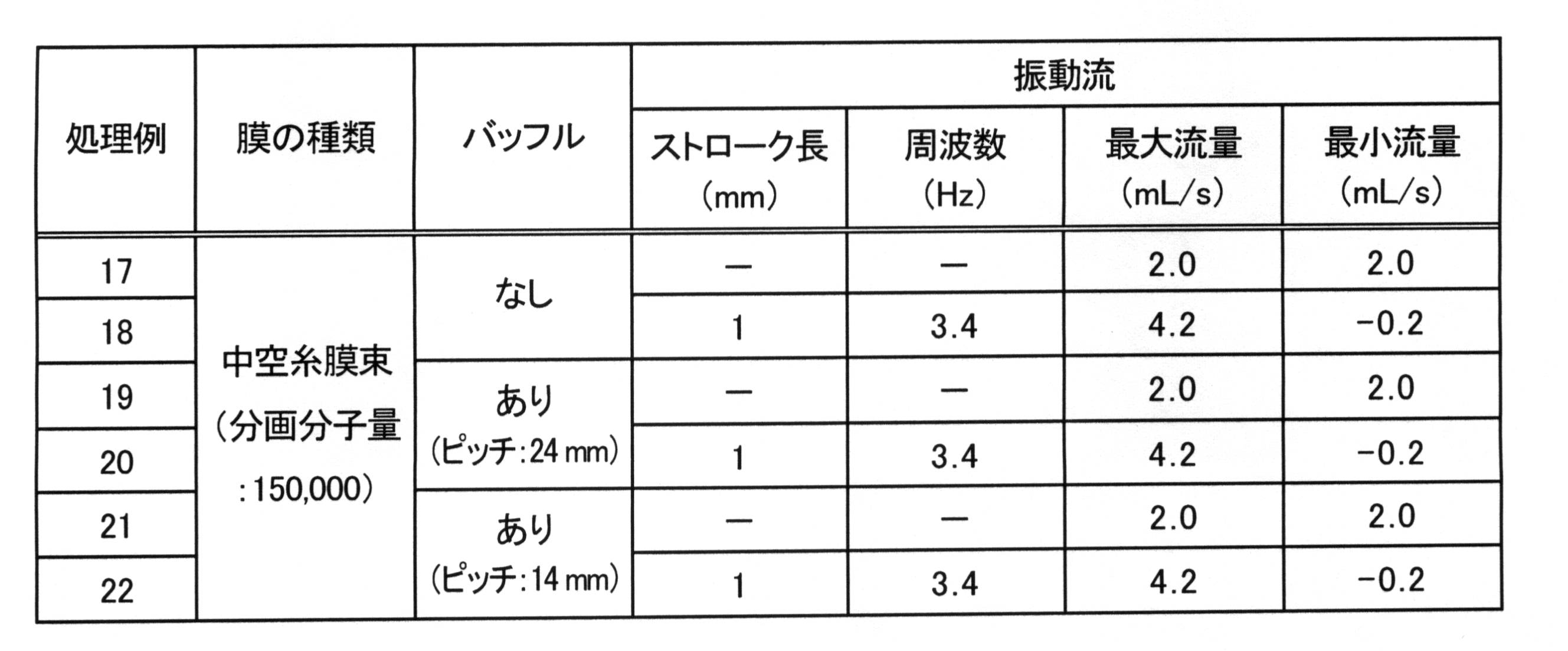
(2-2)膜分離処理方法と処理条件
被処理水として、実験1と同様のフミン酸水溶液を用いて膜分離処理を行った。実験2では、被処理水を平均流量120mL/分(2.0mL/秒)で筐体27内に供給し、表2に示した処理条件に従って、フミン酸水溶液を300分間膜分離処理し、膜処理性能として透過率と阻止率を測定した。また、表2の処理例20および22の条件に対して、周波数や振動体積(ストローク長に比例し、振動流発生装置による被処理水の押し出し容積を意味する)を変えて様々処理を行い、下記式により算出されるストローハル数を指標として、ストローハル数と膜透過流束または阻止率との関係を調べた。なお、ストローハル数は無次元数である。
被処理水として、実験1と同様のフミン酸水溶液を用いて膜分離処理を行った。実験2では、被処理水を平均流量120mL/分(2.0mL/秒)で筐体27内に供給し、表2に示した処理条件に従って、フミン酸水溶液を300分間膜分離処理し、膜処理性能として透過率と阻止率を測定した。また、表2の処理例20および22の条件に対して、周波数や振動体積(ストローク長に比例し、振動流発生装置による被処理水の押し出し容積を意味する)を変えて様々処理を行い、下記式により算出されるストローハル数を指標として、ストローハル数と膜透過流束または阻止率との関係を調べた。なお、ストローハル数は無次元数である。
ストローハル数=v×f/u
v:振動体積(mL)
f:周波数(s-1)
u:平均流量(mL/s)
v:振動体積(mL)
f:周波数(s-1)
u:平均流量(mL/s)
(2-3)処理結果
図10と図11に、処理例17~22の処理結果を示す。図10(a)は透過率の結果を表し、図10(b)は阻止率の結果を表し、図11は処理後の膜外観写真を表す。管状分離膜として中空糸膜束を用いた場合も、バッフルを設置して、振動流を発生させながら膜処理を行うことで、それぞれを単独で行う場合よりも透過率と阻止率が向上した。また処理後の中空糸膜の外観も、バッフルと振動流を組み合わせることにより、膜表面の汚れの付着が低減した。実験2では、バッフルと振動流を組み合わせた場合に、14mmのピッチでバッフルを設置したときの処理性能が、24mmのピッチでバッフルを設置しときの処理性能よりも良くなる結果となった。この理由は次のように推察される。すなわち、14mmのピッチでバッフルを設置した場合には、フミン酸微粒子がバッフルに沿って流れていることが観察されたことから、バッフルのピッチを調整することにより、管軸方向に沿った被処理水の流れと螺旋状の被処理水の流れの両方が好適に形成されたと考えられる。その結果、膜表面でより強力な渦流が発生し、渦流によるせん断力が強化され、膜表面のファウリング層や濃度分極層が減少したと考えられる。
図10と図11に、処理例17~22の処理結果を示す。図10(a)は透過率の結果を表し、図10(b)は阻止率の結果を表し、図11は処理後の膜外観写真を表す。管状分離膜として中空糸膜束を用いた場合も、バッフルを設置して、振動流を発生させながら膜処理を行うことで、それぞれを単独で行う場合よりも透過率と阻止率が向上した。また処理後の中空糸膜の外観も、バッフルと振動流を組み合わせることにより、膜表面の汚れの付着が低減した。実験2では、バッフルと振動流を組み合わせた場合に、14mmのピッチでバッフルを設置したときの処理性能が、24mmのピッチでバッフルを設置しときの処理性能よりも良くなる結果となった。この理由は次のように推察される。すなわち、14mmのピッチでバッフルを設置した場合には、フミン酸微粒子がバッフルに沿って流れていることが観察されたことから、バッフルのピッチを調整することにより、管軸方向に沿った被処理水の流れと螺旋状の被処理水の流れの両方が好適に形成されたと考えられる。その結果、膜表面でより強力な渦流が発生し、渦流によるせん断力が強化され、膜表面のファウリング層や濃度分極層が減少したと考えられる。
図12には、周波数や振動体積を様々変化させて処理を行い、ストローハル数と膜透過流束または阻止率との関係を調べた結果を示した。図12(a)は、ストローハル数と膜透過流束の関係を表し、図12(b)は、ストローハル数と阻止率の関係を表す。ストローハル数が0.5程度までは、ストローハル数が大きくなるにつれて膜透過流束と阻止率が向上する傾向を示したが、それ以上ストローハル数が大きくなっても膜透過流束と阻止率の向上効果はほとんど改善しなかった。また、筐体に導入される被処理水の平均流速が一定の場合は、振動体積と周波数の内訳によらずストローハル数が同じであれば、同じような膜透過流束と阻止率の結果が得られることも明らかになった。ストローハル数はいわば振動の強度を表しており、ストローハル数を大きくするほど、振動流を発生させるエネルギーが増える傾向となる。従って、ストローハル数を指標とすることで、必要最小限のエネルギーで効率的な膜分離処理を行うことが可能となる。
本発明は、廃水処理、浄水処理、製造プロセスにおける分離・濃縮処理、有用物質の分離回収等に適用することができる。
13,24:振動流発生装置
14,25:膜モジュール
15,36:管状分離膜
16,27:筐体
17,28:第1開口
18,29:第2開口
19,30:バッフル
14,25:膜モジュール
15,36:管状分離膜
16,27:筐体
17,28:第1開口
18,29:第2開口
19,30:バッフル
Claims (9)
- 管状分離膜が筐体内に収容された膜モジュールを用いて、被処理水を膜分離処理する方法であって、
筐体には、管状分離膜の外側に、管状分離膜の管軸方向の一方側と他方側に第1開口と第2開口が設けられ、
管状分離膜の外側に、管軸方向に垂直または傾斜するようにバッフルが設けられ、
バッフルを管軸方向に横切って延びる流路が形成され、
被処理水を第1開口から筐体内に導入し、被処理水の第1開口における流速を周期的に変化させることを特徴とする膜分離処理方法。 - 前記バッフルが、管状分離膜から離間して設けられることにより、前記流路が形成されている請求項1に記載の膜分離処理方法。
- 被処理水が第1開口を通じて筐体内へ流入する場合に前記流速が正値をとり、被処理水が第1開口を通じて筐体内から流出する場合に前記流速が負値をとるとしたとき、前記流速が周期的に正値と負値をとるように変化する請求項1または2に記載の膜分離処理方法。
- 前記流速を、0.01秒以上30秒以下の周期で変化させる請求項1~3のいずれか一項に記載の膜分離処理方法。
- 前記管状分離膜が、中空糸膜またはその束である請求項1~4のいずれか一項に記載の膜分離処理方法。
- 管状分離膜と、
管状分離膜を収容し、管状分離膜の外側に、管状分離膜の管軸方向の一方側と他方側に第1開口と第2開口が設けられた筐体と、
管状分離膜の外側に、管軸方向に垂直または傾斜するように設けられたバッフルと、
バッフルを管軸方向に横切って延びる流路と、
筐体内に被処理水を供給するポンプと、
ポンプと第1開口とに連通して設けられ、被処理水が流通する供給管路と、
供給管路に接続して設けられ、供給管路内の被処理水を周期的に引き抜きと押し出しを繰り返す振動流発生装置とを有することを特徴とする膜分離処理システム。 - 前記バッフルが、管状分離膜から離間して設けられることにより、前記流路が形成されている請求項6に記載の膜分離処理システム。
- 前記バッフルは、前記管軸方向に対して45°以上90°以下の角度で設けられている請求項6または7に記載の膜分離処理システム。
- 前記管状分離膜が、中空糸膜またはその束である請求項6~8のいずれか一項に記載の膜分離処理システム。
Priority Applications (1)
| Application Number | Priority Date | Filing Date | Title |
|---|---|---|---|
| JP2015500287A JPWO2014126156A1 (ja) | 2013-02-15 | 2014-02-13 | 膜分離処理方法および膜分離処理システム |
Applications Claiming Priority (2)
| Application Number | Priority Date | Filing Date | Title |
|---|---|---|---|
| JP2013028096 | 2013-02-15 | ||
| JP2013-028096 | 2013-02-15 |
Publications (1)
| Publication Number | Publication Date |
|---|---|
| WO2014126156A1 true WO2014126156A1 (ja) | 2014-08-21 |
Family
ID=51354155
Family Applications (1)
| Application Number | Title | Priority Date | Filing Date |
|---|---|---|---|
| PCT/JP2014/053343 Ceased WO2014126156A1 (ja) | 2013-02-15 | 2014-02-13 | 膜分離処理方法および膜分離処理システム |
Country Status (2)
| Country | Link |
|---|---|
| JP (1) | JPWO2014126156A1 (ja) |
| WO (1) | WO2014126156A1 (ja) |
Cited By (4)
| Publication number | Priority date | Publication date | Assignee | Title |
|---|---|---|---|---|
| KR20180033818A (ko) * | 2016-09-26 | 2018-04-04 | 롯데케미칼 주식회사 | 혐기성 분리막 시스템 및 이를 사용한 수처리 방법 |
| CN111362494A (zh) * | 2020-02-17 | 2020-07-03 | 武汉天源环保股份有限公司 | 一种垃圾填埋场膜浓缩渗滤液处理方法 |
| CN115069089A (zh) * | 2022-07-25 | 2022-09-20 | 北京建筑大学 | 一种正渗透污泥深度脱水装置 |
| CN115888394A (zh) * | 2021-08-14 | 2023-04-04 | 江苏泷膜环境科技有限公司 | 一种反渗透膜元件及滤芯 |
Citations (5)
| Publication number | Priority date | Publication date | Assignee | Title |
|---|---|---|---|---|
| JPS5751603U (ja) * | 1980-09-03 | 1982-03-25 | ||
| US4668401A (en) * | 1985-06-19 | 1987-05-26 | Mitsubishi Rayon Co., Ltd. | Hollow-fiber filter module and filtration method using the same |
| JPS634809A (ja) * | 1986-06-23 | 1988-01-09 | Mitsubishi Rayon Co Ltd | 中空糸濾過モジユ−ル |
| JPH06226060A (ja) * | 1993-02-05 | 1994-08-16 | Daicel Chem Ind Ltd | 中空糸膜型エレメントおよび膜分離方法 |
| JP2003103151A (ja) * | 2001-09-28 | 2003-04-08 | Mitsui Eng & Shipbuild Co Ltd | 膜表面に流体の混合促進手段を配置した分離膜ユニット |
-
2014
- 2014-02-13 JP JP2015500287A patent/JPWO2014126156A1/ja active Pending
- 2014-02-13 WO PCT/JP2014/053343 patent/WO2014126156A1/ja not_active Ceased
Patent Citations (5)
| Publication number | Priority date | Publication date | Assignee | Title |
|---|---|---|---|---|
| JPS5751603U (ja) * | 1980-09-03 | 1982-03-25 | ||
| US4668401A (en) * | 1985-06-19 | 1987-05-26 | Mitsubishi Rayon Co., Ltd. | Hollow-fiber filter module and filtration method using the same |
| JPS634809A (ja) * | 1986-06-23 | 1988-01-09 | Mitsubishi Rayon Co Ltd | 中空糸濾過モジユ−ル |
| JPH06226060A (ja) * | 1993-02-05 | 1994-08-16 | Daicel Chem Ind Ltd | 中空糸膜型エレメントおよび膜分離方法 |
| JP2003103151A (ja) * | 2001-09-28 | 2003-04-08 | Mitsui Eng & Shipbuild Co Ltd | 膜表面に流体の混合促進手段を配置した分離膜ユニット |
Cited By (4)
| Publication number | Priority date | Publication date | Assignee | Title |
|---|---|---|---|---|
| KR20180033818A (ko) * | 2016-09-26 | 2018-04-04 | 롯데케미칼 주식회사 | 혐기성 분리막 시스템 및 이를 사용한 수처리 방법 |
| CN111362494A (zh) * | 2020-02-17 | 2020-07-03 | 武汉天源环保股份有限公司 | 一种垃圾填埋场膜浓缩渗滤液处理方法 |
| CN115888394A (zh) * | 2021-08-14 | 2023-04-04 | 江苏泷膜环境科技有限公司 | 一种反渗透膜元件及滤芯 |
| CN115069089A (zh) * | 2022-07-25 | 2022-09-20 | 北京建筑大学 | 一种正渗透污泥深度脱水装置 |
Also Published As
| Publication number | Publication date |
|---|---|
| JPWO2014126156A1 (ja) | 2017-02-02 |
Similar Documents
| Publication | Publication Date | Title |
|---|---|---|
| JP5923294B2 (ja) | 逆浸透処理装置 | |
| KR102046685B1 (ko) | 역삼투압 필터 모듈 | |
| JP2001518005A (ja) | 水処理 | |
| US12364953B2 (en) | Tubular membrane including a vortex generator that produces spiral fluid flow | |
| JP5828328B2 (ja) | 逆浸透膜装置の運転方法、及び逆浸透膜装置 | |
| WO2014126156A1 (ja) | 膜分離処理方法および膜分離処理システム | |
| JP6183213B2 (ja) | 造水方法および造水装置 | |
| WO2013111826A1 (ja) | 造水方法および造水装置 | |
| CN103857629A (zh) | 水处理单元和水处理装置 | |
| ZHENG | Flux enhancement during ultrafiltration of produced water using turbulence promoter | |
| WO2016027302A1 (ja) | 逆浸透膜装置及びその運転方法 | |
| CN103764571A (zh) | 海水淡化方法 | |
| WO2019191472A1 (en) | Method and apparatus for improved filtration by a ceramic membrane | |
| JP4525857B1 (ja) | 水処理システムの前処理装置及び前処理方法 | |
| JP2013119042A (ja) | 水処理方法 | |
| Cui et al. | Influence of selective permeation of backwashing solution on the cleaning effectiveness in hollow fiber system | |
| Yun et al. | Water treatment application of a large pore micro-filtration membrane and its problems | |
| CN103857461A (zh) | 分离膜、水处理单元和水处理装置 | |
| JP2016172238A (ja) | 脱塩方法、脱塩装置の洗浄方法及び脱塩装置 | |
| CN103253803A (zh) | 一种纯水处理设备 | |
| US10570042B2 (en) | Vacuum enhanced operation method for forward osmosis membrane bioreactors | |
| WO2017183131A1 (ja) | ろ過処理設備及びこれを備えた淡水化プラント並びにろ過処理方法 | |
| JP2011167668A (ja) | 水処理装置 | |
| CN217535536U (zh) | 淡化海水装置 | |
| JP2011167669A (ja) | 水処理装置 |
Legal Events
| Date | Code | Title | Description |
|---|---|---|---|
| DPE2 | Request for preliminary examination filed before expiration of 19th month from priority date (pct application filed from 20040101) | ||
| 121 | Ep: the epo has been informed by wipo that ep was designated in this application |
Ref document number: 14751465 Country of ref document: EP Kind code of ref document: A1 |
|
| ENP | Entry into the national phase |
Ref document number: 2015500287 Country of ref document: JP Kind code of ref document: A |
|
| NENP | Non-entry into the national phase |
Ref country code: DE |
|
| 122 | Ep: pct application non-entry in european phase |
Ref document number: 14751465 Country of ref document: EP Kind code of ref document: A1 |