WO2014125845A1 - Conveyance system - Google Patents
Conveyance system Download PDFInfo
- Publication number
- WO2014125845A1 WO2014125845A1 PCT/JP2014/050154 JP2014050154W WO2014125845A1 WO 2014125845 A1 WO2014125845 A1 WO 2014125845A1 JP 2014050154 W JP2014050154 W JP 2014050154W WO 2014125845 A1 WO2014125845 A1 WO 2014125845A1
- Authority
- WO
- WIPO (PCT)
- Prior art keywords
- transport
- foup
- conveyance
- transport vehicle
- detected
- Prior art date
Links
Images

Classifications
-
- B—PERFORMING OPERATIONS; TRANSPORTING
- B61—RAILWAYS
- B61L—GUIDING RAILWAY TRAFFIC; ENSURING THE SAFETY OF RAILWAY TRAFFIC
- B61L23/00—Control, warning, or like safety means along the route or between vehicles or vehicle trains
-
- B—PERFORMING OPERATIONS; TRANSPORTING
- B61—RAILWAYS
- B61B—RAILWAY SYSTEMS; EQUIPMENT THEREFOR NOT OTHERWISE PROVIDED FOR
- B61B13/00—Other railway systems
-
- B—PERFORMING OPERATIONS; TRANSPORTING
- B61—RAILWAYS
- B61B—RAILWAY SYSTEMS; EQUIPMENT THEREFOR NOT OTHERWISE PROVIDED FOR
- B61B3/00—Elevated railway systems with suspended vehicles
-
- B—PERFORMING OPERATIONS; TRANSPORTING
- B61—RAILWAYS
- B61B—RAILWAY SYSTEMS; EQUIPMENT THEREFOR NOT OTHERWISE PROVIDED FOR
- B61B3/00—Elevated railway systems with suspended vehicles
- B61B3/02—Elevated railway systems with suspended vehicles with self-propelled vehicles
-
- B—PERFORMING OPERATIONS; TRANSPORTING
- B61—RAILWAYS
- B61L—GUIDING RAILWAY TRAFFIC; ENSURING THE SAFETY OF RAILWAY TRAFFIC
- B61L11/00—Operation of points from the vehicle or by the passage of the vehicle
Definitions
- the present invention relates to a transport system.
- Patent Document 1 As a conventional transport system, for example, the one described in Patent Document 1 is known.
- an area where the transport vehicle can travel is set as a travel area among a plurality of areas according to the type of the transport vehicle, and the transport vehicle is set in an area other than the set travel area. Is controlled not to enter.
- the transport cart may accidentally enter an area where entry is not permitted.
- the transport cart and the apparatus may interfere with each other in an area that is not designed with the entrance of the transport cart.
- This invention was made in order to solve the said subject, and it aims at providing the conveyance system which can prevent the erroneous approach of a conveyance trolley
- a transport system includes a track laid over a plurality of areas, a first transport cart that travels along the track, a travel along the track, a first transport cart, a width, It is provided in one of the second transport cart, the first transport cart, and the second transport cart, which are different in at least one of the heights, and is disposed at a position that does not overlap with the other transport cart in the travel direction.
- a sensor that detects obstacles ahead and an entry area to a specific area that allows entry of only the other conveyance carriage among a plurality of areas allow entry of the other conveyance carriage to a specific area.
- a member to be detected that is disposed at a position that is detected by a sensor provided on one of the transport carriages.
- This transport system includes a first transport cart, and a first transport cart and a second transport cart that is different in at least one of width and height.
- One of the first transport cart and the second transport cart is provided with a sensor for detecting a front obstacle, and this sensor is provided only for the other transport cart among a plurality of areas.
- the detected member arranged at a position where the other transport carriage is allowed to enter the specific area is detected. Accordingly, in the transport system, one transport carriage that is not allowed to enter a specific area can recognize the area that is not allowed to enter by detecting the detected member by the sensor. Therefore, in the transfer system, the erroneous entry of the transfer cart can be prevented.
- the track is a ceiling track laid on or near the ceiling, and the first and second transport carts are suspended carts that run suspended from the ceiling track,
- the conveyance carriage has a height dimension larger than that of the other conveyance carriage, and the sensor may be arranged within a range below the lower end of the other conveyance carriage by a predetermined height in one conveyance carriage. Good.
- the sensor is disposed at a position where one transport carriage does not overlap with the other transport carriage, so that the detected member can be disposed at a position where it does not contact the other transport carriage.
- a transport system including a suspended cart (ceiling transport vehicle) contact between an apparatus set on the floor and one transport cart in a specific area can be prevented.
- a contact sensor may be provided that is provided on one of the transport carriages, is disposed at a position in contact with the detected member, and detects contact with the detected member.
- the member to be detected is arranged at a position where it is not detected by a sensor provided on one of the transport carriages at a position where the member does not enter the specific area.
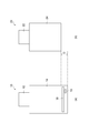
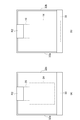
- FIG. 1 is a diagram schematically illustrating a transport system according to an embodiment.
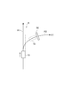
- FIG. 2 is a front view of the FOUP transport vehicle and the reticle transport vehicle.
- FIG. 3 is a diagram showing the configuration of the FOUP transport vehicle.
- FIG. 4 is an enlarged view of a part of the rail.
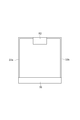
- FIG. 5 is a front view showing the member to be detected.
- FIG. 6 is a diagram illustrating the relationship between the member to be detected, the FOUP transport vehicle, and the reticle transport vehicle.
- FIG. 1 is a diagram illustrating a transport system according to an embodiment.
- FIG. 2 is a front view of the FOUP transport vehicle and the reticle transport vehicle.
- the transport system 1 includes a rail (track, ceiling track) R, a FOUP transport vehicle (first transport cart) 10 that travels on the rail R, and a reticle transport vehicle (first transport vehicle) that travels on the rail R. 2 transport carts) 20.
- a plurality of types of suspended transport carts (FOUP transport vehicle 10 and reticle transport vehicle 20) travel on the same rail R.
- the rail R is laid on or near the ceiling.
- the rail R includes a main rail R1 and branching / merging rails R2 to R6 that branch or merge from the main rail R1.
- the main rail R1 constitutes an interbay
- the branching / merging rails R2 to R6 constitute an intrabay.
- the branching / merging rails R2 to R6 are respectively laid in a plurality (here, five) of areas A1 to A5. That is, the rail R is laid over a plurality of areas A1 to A5.
- Various devices and stockers (not shown) are arranged in each of the areas A1 to A5. In the transport system 1, entry of the FOUP transport vehicle 10 or the reticle transport vehicle 20 is restricted in any one of the areas A1 to A5.
- the reticle carrier 20 is an OHT (Overhead Hoist Transport) that carries a reticle Smifpod (Reticle SMIF Pod) containing a reticle.
- the reticle transport vehicle 20 includes a traveling unit 22 that travels on the rail R, and a main body unit 24 that includes a hoist, a belt, a gripper, and the like.
- the reticle transport vehicle 20 transports the reticle smiff pod, enters the area where the reticle transport vehicle 20 is permitted to enter, and places the reticle smiff pod between the various processing apparatuses and the warehousing ports provided in the stocker. It is configured to be transferable.
- the FOUP transport vehicle 10 is an OHT that transports a FOUP (Front-Opening Unified pod) containing a wafer.
- the FOUP conveyance vehicle 10 includes a traveling unit 12 that travels on the rail R, and a main body unit 14 that includes a hoist, a belt, a gripper, and the like.
- the FOUP transport vehicle 10 can transport the FOUP, enter the area where the FOUP transport vehicle 10 is permitted to enter, and transfer the FOUP between various wafer processing apparatuses and warehousing ports provided in the stocker. It is configured.
- the FOUP transport vehicle 10 is larger than the reticle transport vehicle 20.
- the height dimension of the main body 14 of the FOUP transport vehicle 10 is larger than that of the reticle transport vehicle 20.
- a difference D in height dimension between the FOUP conveyance vehicle 10 and the reticle conveyance vehicle 20 is, for example, about 100 mm. That is, the FOUP transport vehicle 10 has a region that does not overlap the reticle transport vehicle 20 in the traveling direction of traveling on the rail R.
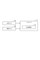
- FIG. 3 is a diagram showing the configuration of the FOUP transport vehicle.
- the FOUP transport vehicle 10 includes an optical sensor 15, a contact sensor 16, and a controller 17.
- the optical sensor 15 detects an obstacle in front of the FOUP transport vehicle 10.
- the optical sensor 15 is disposed at the lower end of the main body 14.
- the optical sensor 15 has a predetermined height from the lower end of the main body 24 of the reticle transport vehicle 20 within a region that does not overlap with the reticle transport vehicle 20, that is, within the range of the height difference D from the reticle transport vehicle 20. (Within the lower range).
- the detection area of the optical sensor 15 has a height width of about 100 mm at a distance of 5 m, for example.
- the contact sensor 16 detects contact with an obstacle.
- the contact sensor 16 is disposed at the lower end portion of the main body portion 14.
- the optical sensor 15 is disposed in a region that does not overlap with the reticle transport vehicle 20, that is, in the range of the height dimension difference D from the reticle transport vehicle 20.
- the contact sensor 16 is disposed above the optical sensor 15.
- the contact sensor 16 extends along the width direction of the main body 14 and also functions as a bumper. When the contact sensor 16 detects contact with an obstacle, the contact sensor 16 outputs detection information to the controller 17.
- the controller 17 is a control device that controls the operation of the FOUP transport vehicle 10.
- the controller 17 controls each part of the FOUP transport vehicle 10 (traveling unit 12, hoist, etc.).
- the controller 17 includes a travel control unit 18.
- the travel control unit 18 controls the FOUP transport vehicle 10 to travel to a specified address based on a command from a transport instruction unit (not shown).
- the traveling control unit 18 receives the detection information output from the optical sensor 15 or the contact sensor 16, the traveling control unit 18 causes the traveling unit 12 to perform braking control. That is, the FOUP transport vehicle 10 stops traveling when an obstacle is detected by the optical sensor 15 or when contact with the obstacle is detected by the contact sensor 16.
- entry of the FOUP transport vehicle 10 or the reticle transport vehicle 20 is restricted in any one of the areas A1 to A5.
- area A1 the entry of the FOUP transport vehicle 10 is not permitted (the entry of the FOUP transport vehicle 10 is restricted). Therefore, in the transport system 1, as shown in FIG. 4, the detected member 30 is provided in the entry region of the branch / merging rail R2 that branches from the main rail R1 to the area A1.
- FIG. 5 is a front view showing a member to be detected.
- the member 30 to be detected is, for example, a plate member. Both ends of the detected member 30 are supported by the branching / merging rail R2 by support members 32a and 32b. Specifically, the detected member 30 is located at a predetermined height below the branching / merging rail R2 and extends in a direction intersecting the extending direction of the branching / merging rail R2.
- the detected member 30 is an obstacle detected by the optical sensor 15 and the contact sensor 16 of the FOUP transport vehicle 10.
- the member 30 to be detected is disposed in a detection range of the optical sensor 15 and the contact sensor 16 of the FOUP transport vehicle 10 and at a position where it does not contact the reticle transport vehicle 20.
- the member 30 to be detected permits passage of the reticle transport vehicle 20, but does not permit passage of the FOUP transport vehicle 10 in contact with the FOUP transport vehicle 10. That is, in the transport system 1, the reticle transport vehicle 20 is allowed to enter the area A1 by the detected member 30, and the FOUP transport vehicle 10 is restricted from entering the area A1 by the detected member 30.
- the detected member 30 is a subsequent FOUP transport vehicle 10 or reticle in which the FOUP transport vehicle 10 travels on the main rail R1. It arrange
- the FOUP transport vehicle 10 and the reticle transport vehicle 20 that travel on the rail R1 are disposed so as to stop at positions that do not overlap. Further, the detected member 30 is disposed at a position that does not enter the detection region of the optical sensor 15 of the FOUP transport vehicle 10 that travels on the main rail R1.
- the FOUP transport vehicle 10 that has detected and stopped the detected member 30 is manually returned to the main rail R1, for example. Further, in the transfer system 1, when a command for the reticle transfer vehicle 20 to enter the branching / merging rail where the FOUP transfer vehicle 10 is stopped is received, information indicating that the FOUP transfer vehicle 10 is stopped is received. Then, reticle transport vehicle 20 is controlled to travel on main rail R1 until FOUP transport vehicle 10 is returned to main rail R1.
- the FOUP transport vehicle 10 includes the optical sensor 15 that detects a front obstacle at the lower end portion of the main body 14 that does not overlap the reticle transport vehicle 20 in the traveling direction. Is provided.
- the optical sensor 15 is arranged at a position that allows the reticle transport vehicle 20 to enter a specific area in an entry region to a specific area that allows only the reticle transport vehicle 20 to enter among the plurality of areas A1 to A5.
- the detected member 30 is detected.
- the FOUP transport vehicle 10 that is not allowed to enter a specific area can recognize the area that is not allowed to enter by detecting the detected member 30 by the optical sensor 15. Therefore, in the conveyance system 1, it is possible to prevent the erroneous entry of the conveyance carriage.
- the transport system 1 contact between the device installed on the floor and the FOUP transport vehicle 10 in a specific area is prevented.
- the height of the apparatus is also set based on, for example, the travel height of the reticle transport vehicle 20 since it is not set assuming the entrance of the FOUP transport vehicle 10. Is set. Therefore, in a specific area, when the FOUP transport vehicle 10 enters, there is a risk of contact with the apparatus. Therefore, the configuration of the transport system 1 is particularly effective in the configuration of the present embodiment in which transport is performed by the ceiling transport vehicle.
- the conveyance system 1 can prevent the conveyance carriage from erroneously entering by providing the optical sensor 15 in the FOUP conveyance vehicle 10 and providing the detected member 30 detected by the optical sensor 15. Therefore, in the transport system 1, it is possible to prevent erroneous entry of the transport carriage with a simple configuration. Moreover, the conveyance system 1 is applicable also to the existing system.
- the FOUP transport vehicle 10 includes a contact sensor 16 attached at a position where the FOUP transport vehicle 10 contacts the detected member 30.
- the detected member 30 is connected to the subsequent FOUP transport vehicle 10 or reticle transport vehicle 20 on which the FOUP transport vehicle 10 travels on the main rail R1. It is placed in a position that does not interfere.
- the subsequent FOUP transport vehicle 10 or reticle transport vehicle 20 Traveling can be continued.
- the detected member 30 is arranged at a position that does not enter the detection area of the optical sensor 15 of the FOUP transport vehicle 10 that travels on the main rail R1. Thereby, in the conveyance system 1, the malfunction which the optical sensor 15 of the FOUP conveyance vehicle 10 which drive
- the present invention is not limited to the above embodiment.
- the FOUP conveyance vehicle 10 and the reticle conveyance vehicle 20 which are ceiling conveyance vehicles have been described as an example.
- the conveyance vehicle may be a carriage traveling on the floor.
- the height dimension of the FOUP conveyance vehicle 10 is larger than the height dimension of the reticle conveyance vehicle 20 is taken as an example, and a configuration in which a sensor is provided at the lower end of the main body 14 of the FOUP conveyance vehicle 10 will be described.
- the sensor may be attached to one end portion in the width direction.
- SYMBOLS 1 DESCRIPTION OF SYMBOLS 1 ... Conveyance system, 10 ... FOUP conveyance vehicle (1st conveyance vehicle, one conveyance vehicle), 15 ... Optical sensor, 16 ... Contact sensor, 20 ... Reticle conveyance vehicle (2nd conveyance vehicle, the other conveyance vehicle) 30 ... detected members, A1 to A5 ... area, R ... rail.
Abstract
Description
Claims (4)
- 複数のエリアにわたって敷設された軌道と、
前記軌道に沿って走行する第1の搬送台車と、
前記軌道に沿って走行すると共に、前記第1の搬送台車と幅及び高さの少なくとも一方が異なる第2の搬送台車と、
前記第1の搬送台車及び前記第2の搬送台車のうちの一方の搬送台車に設けられ、他方の搬送台車と走行方向において重ならない位置に配置されると共に、前方の障害物を検出するセンサと、
前記複数のエリアのうち前記他方の搬送台車のみの進入を許容する特定のエリアへの進入領域において、前記他方の搬送台車の前記特定のエリアへの進入を許容する位置で且つ前記一方の搬送台車に設けられた前記センサにより検出される位置に配置された被検出部材と、を備えることを特徴とする搬送システム。 A track laid over multiple areas,
A first transport carriage that travels along the track;
A second transport cart that travels along the track and is different from the first transport cart in at least one of width and height;
A sensor that is provided on one of the first transport cart and the second transport cart, is disposed at a position that does not overlap the other transport cart in the traveling direction, and detects a front obstacle; ,
Of the plurality of areas, in the entry area to the specific area where only the other transport cart is allowed to enter, the one transport cart is at a position allowing the other transport cart to enter the specific area. And a member to be detected disposed at a position detected by the sensor provided in the transport system. - 前記軌道は、天井又は天井近傍に敷設された天井軌道であり、
前記第1及び前記第2の搬送台車は、前記天井軌道から吊り下げられて走行する懸垂式の台車であり、
前記一方の搬送台車は、前記他方の搬送台車よりも高さ寸法が大きくされており、
前記センサは、前記一方の搬送台車において、前記他方の搬送台車の下端部から所定高さだけ下の範囲内に配置されていることを特徴とする請求項1記載の搬送システム。 The track is a ceiling track laid on or near the ceiling,
The first and second transport carts are suspended carts that run suspended from the ceiling track.
The one transport carriage has a height dimension larger than that of the other transport carriage,
2. The transport system according to claim 1, wherein the sensor is arranged in a range of a predetermined height below a lower end portion of the other transport cart in the one transport cart. - 前記一方の搬送台車に設けられ、前記被検出部材と接触する位置に配置されると共に、前記被検出部材との接触を検出する接触センサを備えることを特徴とする請求項1又は2記載の搬送システム。 The conveyance according to claim 1, further comprising a contact sensor that is provided on the one conveyance carriage and is disposed at a position in contact with the detected member, and that detects contact with the detected member. system.
- 前記被検出部材は、前記特定のエリアへの進入領域に進入していない位置では前記一方の搬送台車に設けられた前記センサにより検出されない位置に配置されていることを特徴とする請求項1~3のいずれか一項記載の搬送システム。 The detection target member is arranged at a position that is not detected by the sensor provided on the one conveyance carriage at a position where the detection target member does not enter the entry area to the specific area. The conveyance system as described in any one of 3.
Priority Applications (6)
| Application Number | Priority Date | Filing Date | Title |
|---|---|---|---|
| US14/767,321 US9834236B2 (en) | 2013-02-15 | 2014-01-08 | Conveyance system |
| CN201480008754.XA CN105009013A (en) | 2013-02-15 | 2014-01-08 | Conveyance system |
| EP14751764.3A EP2957974B1 (en) | 2013-02-15 | 2014-01-08 | Conveyance system |
| KR1020157024847A KR101733717B1 (en) | 2013-02-15 | 2014-01-08 | Conveyance system |
| SG11201506361WA SG11201506361WA (en) | 2013-02-15 | 2014-01-08 | Conveyance system |
| JP2015500157A JP5983855B2 (en) | 2013-02-15 | 2014-01-08 | Transport system |
Applications Claiming Priority (2)
| Application Number | Priority Date | Filing Date | Title |
|---|---|---|---|
| JP2013027542 | 2013-02-15 | ||
| JP2013-027542 | 2013-02-15 |
Publications (1)
| Publication Number | Publication Date |
|---|---|
| WO2014125845A1 true WO2014125845A1 (en) | 2014-08-21 |
Family
ID=51353856
Family Applications (1)
| Application Number | Title | Priority Date | Filing Date |
|---|---|---|---|
| PCT/JP2014/050154 WO2014125845A1 (en) | 2013-02-15 | 2014-01-08 | Conveyance system |
Country Status (8)
| Country | Link |
|---|---|
| US (1) | US9834236B2 (en) |
| EP (1) | EP2957974B1 (en) |
| JP (1) | JP5983855B2 (en) |
| KR (1) | KR101733717B1 (en) |
| CN (1) | CN105009013A (en) |
| SG (1) | SG11201506361WA (en) |
| TW (1) | TWI585562B (en) |
| WO (1) | WO2014125845A1 (en) |
Families Citing this family (8)
| Publication number | Priority date | Publication date | Assignee | Title |
|---|---|---|---|---|
| JP6358142B2 (en) * | 2015-03-26 | 2018-07-18 | 株式会社ダイフク | Goods transport equipment |
| JP6304122B2 (en) * | 2015-05-13 | 2018-04-04 | 株式会社ダイフク | Goods transport equipment |
| JP6520797B2 (en) * | 2016-04-11 | 2019-05-29 | 株式会社ダイフク | Goods transport equipment |
| JP6809062B2 (en) * | 2016-09-09 | 2021-01-06 | 株式会社ダイフク | Goods transport equipment |
| JP6693481B2 (en) * | 2017-06-26 | 2020-05-13 | 株式会社ダイフク | Article transport equipment and article transport vehicle |
| SG11202104302QA (en) * | 2018-10-29 | 2021-05-28 | Murata Machinery Ltd | Ceiling traveling vehicle, ceiling traveling vehicle system, and method for detecting obstacle |
| CN110253534B (en) * | 2019-06-05 | 2021-07-02 | 北京英鸿光大科技有限公司 | Nanofiber production is with inspection robot device of going upstairs or downstairs |
| CN110253535B (en) * | 2019-06-05 | 2021-06-04 | 北京英鸿光大科技有限公司 | Inspection robot for nanofiber production |
Citations (7)
| Publication number | Priority date | Publication date | Assignee | Title |
|---|---|---|---|---|
| JPS5933513A (en) * | 1982-08-18 | 1984-02-23 | Daifuku Co Ltd | Truck guidance equipment |
| JP2002019605A (en) * | 2000-07-11 | 2002-01-23 | Shinko Electric Co Ltd | Temporary stop device for overhead carrying truck and lifting implement for it |
| JP2005124753A (en) * | 2003-10-22 | 2005-05-19 | Sharp Corp | Self-propelling type vacuum cleaner |
| JP2008186340A (en) * | 2007-01-31 | 2008-08-14 | Murata Mach Ltd | Running vehicle system |
| JP2009282958A (en) * | 2008-04-24 | 2009-12-03 | Panasonic Electric Works Co Ltd | Autonomous moving device |
| JP2010067028A (en) | 2008-09-11 | 2010-03-25 | Muratec Automation Co Ltd | Transfer control device and transfer system |
| JP2012063920A (en) * | 2010-09-15 | 2012-03-29 | Murata Mach Ltd | Carrier system |
Family Cites Families (12)
| Publication number | Priority date | Publication date | Assignee | Title |
|---|---|---|---|---|
| US4319675A (en) | 1979-10-22 | 1982-03-16 | Alvey, Inc. | Roller conveyor |
| GB2110448B (en) | 1981-09-04 | 1986-01-22 | Plessey Co Plc | Material handling and sorting system |
| FR2705636B1 (en) * | 1993-05-26 | 1995-07-07 | Lohr Ind | Directional guide assembly for a road vehicle along a rail. |
| KR100729986B1 (en) * | 1999-12-20 | 2007-06-20 | 아시스트 신꼬, 인코포레이티드 | Auto-carrying system |
| JP4323072B2 (en) * | 2000-09-08 | 2009-09-02 | 三井化学株式会社 | Reflective sheet and reflector using the same |
| JP3508130B2 (en) * | 2000-09-21 | 2004-03-22 | 村田機械株式会社 | Transport system |
| US7353955B2 (en) | 2003-07-16 | 2008-04-08 | Siemens Energy & Automation, Inc. | Baggage screening system and method |
| JP4720267B2 (en) * | 2005-04-14 | 2011-07-13 | 村田機械株式会社 | Overhead traveling vehicle system |
| TW200817863A (en) * | 2006-07-14 | 2008-04-16 | Yazaki Ind Chem Co Ltd | Work conveyance facility system by automated guided vehicle and work mounting truck |
| JP5263613B2 (en) * | 2009-05-11 | 2013-08-14 | 株式会社ダイフク | Goods transport equipment |
| JP5440870B2 (en) * | 2010-08-19 | 2014-03-12 | 株式会社ダイフク | Goods transport equipment |
| JP5741034B2 (en) | 2011-02-09 | 2015-07-01 | 村田機械株式会社 | Tracked cart system |
-
2014
- 2014-01-08 CN CN201480008754.XA patent/CN105009013A/en active Pending
- 2014-01-08 EP EP14751764.3A patent/EP2957974B1/en active Active
- 2014-01-08 SG SG11201506361WA patent/SG11201506361WA/en unknown
- 2014-01-08 WO PCT/JP2014/050154 patent/WO2014125845A1/en active Application Filing
- 2014-01-08 JP JP2015500157A patent/JP5983855B2/en active Active
- 2014-01-08 KR KR1020157024847A patent/KR101733717B1/en active IP Right Grant
- 2014-01-08 US US14/767,321 patent/US9834236B2/en active Active
- 2014-02-12 TW TW103104575A patent/TWI585562B/en active
Patent Citations (7)
| Publication number | Priority date | Publication date | Assignee | Title |
|---|---|---|---|---|
| JPS5933513A (en) * | 1982-08-18 | 1984-02-23 | Daifuku Co Ltd | Truck guidance equipment |
| JP2002019605A (en) * | 2000-07-11 | 2002-01-23 | Shinko Electric Co Ltd | Temporary stop device for overhead carrying truck and lifting implement for it |
| JP2005124753A (en) * | 2003-10-22 | 2005-05-19 | Sharp Corp | Self-propelling type vacuum cleaner |
| JP2008186340A (en) * | 2007-01-31 | 2008-08-14 | Murata Mach Ltd | Running vehicle system |
| JP2009282958A (en) * | 2008-04-24 | 2009-12-03 | Panasonic Electric Works Co Ltd | Autonomous moving device |
| JP2010067028A (en) | 2008-09-11 | 2010-03-25 | Muratec Automation Co Ltd | Transfer control device and transfer system |
| JP2012063920A (en) * | 2010-09-15 | 2012-03-29 | Murata Mach Ltd | Carrier system |
Also Published As
| Publication number | Publication date |
|---|---|
| KR101733717B1 (en) | 2017-05-10 |
| JP5983855B2 (en) | 2016-09-06 |
| SG11201506361WA (en) | 2015-09-29 |
| JPWO2014125845A1 (en) | 2017-02-02 |
| KR20150119183A (en) | 2015-10-23 |
| US20160031460A1 (en) | 2016-02-04 |
| EP2957974B1 (en) | 2020-03-11 |
| TW201435531A (en) | 2014-09-16 |
| EP2957974A1 (en) | 2015-12-23 |
| CN105009013A (en) | 2015-10-28 |
| EP2957974A4 (en) | 2016-11-23 |
| US9834236B2 (en) | 2017-12-05 |
| TWI585562B (en) | 2017-06-01 |
Similar Documents
| Publication | Publication Date | Title |
|---|---|---|
| JP5983855B2 (en) | Transport system | |
| US9758308B1 (en) | Article transport facility | |
| JP5071695B2 (en) | Traveling vehicle system and travel control method in traveling vehicle system | |
| US9934993B2 (en) | Article transport facility | |
| US8104722B2 (en) | Transporting system, and method of controlling the transporting system | |
| KR20180123628A (en) | Article transport vehicle | |
| JP4074999B2 (en) | Conveyor cart system | |
| JP2007025743A (en) | Conveyance truck system | |
| JP4172466B2 (en) | Conveyor cart system | |
| WO2012098761A1 (en) | Rail vehicle system | |
| WO2021002042A1 (en) | Travel system | |
| JP2005301364A (en) | Carrier truck system | |
| JP5170190B2 (en) | Transport vehicle system | |
| KR101341428B1 (en) | BARNCHING AND JOINING SYSTEM OF OVER HOIST TRANSFER(or OverHead Shuttle) AND CONTROL METHOD THEREOF | |
| JP2008171088A (en) | Traveling vehicle system | |
| TW202301057A (en) | Rail-guided carrier system | |
| JP2010188866A (en) | Movable rail device | |
| KR20210087212A (en) | Transfer apparatus | |
| JP2010064855A (en) | Conveying system and computer program |
Legal Events
| Date | Code | Title | Description |
|---|---|---|---|
| 121 | Ep: the epo has been informed by wipo that ep was designated in this application |
Ref document number: 14751764 Country of ref document: EP Kind code of ref document: A1 |
|
| ENP | Entry into the national phase |
Ref document number: 2015500157 Country of ref document: JP Kind code of ref document: A |
|
| WWE | Wipo information: entry into national phase |
Ref document number: 14767321 Country of ref document: US |
|
| NENP | Non-entry into the national phase |
Ref country code: DE |
|
| WWE | Wipo information: entry into national phase |
Ref document number: 2014751764 Country of ref document: EP |
|
| ENP | Entry into the national phase |
Ref document number: 20157024847 Country of ref document: KR Kind code of ref document: A |