WO2014123011A1 - Cleaning tool - Google Patents
Cleaning tool Download PDFInfo
- Publication number
- WO2014123011A1 WO2014123011A1 PCT/JP2014/051586 JP2014051586W WO2014123011A1 WO 2014123011 A1 WO2014123011 A1 WO 2014123011A1 JP 2014051586 W JP2014051586 W JP 2014051586W WO 2014123011 A1 WO2014123011 A1 WO 2014123011A1
- Authority
- WO
- WIPO (PCT)
- Prior art keywords
- region
- cleaning tool
- sheet
- cleaning
- fiber
- Prior art date
Links
Images


Classifications
-
- A—HUMAN NECESSITIES
- A47—FURNITURE; DOMESTIC ARTICLES OR APPLIANCES; COFFEE MILLS; SPICE MILLS; SUCTION CLEANERS IN GENERAL
- A47L—DOMESTIC WASHING OR CLEANING; SUCTION CLEANERS IN GENERAL
- A47L13/00—Implements for cleaning floors, carpets, furniture, walls, or wall coverings
- A47L13/10—Scrubbing; Scouring; Cleaning; Polishing
- A47L13/38—Other dusting implements
-
- A—HUMAN NECESSITIES
- A47—FURNITURE; DOMESTIC ARTICLES OR APPLIANCES; COFFEE MILLS; SPICE MILLS; SUCTION CLEANERS IN GENERAL
- A47L—DOMESTIC WASHING OR CLEANING; SUCTION CLEANERS IN GENERAL
- A47L13/00—Implements for cleaning floors, carpets, furniture, walls, or wall coverings
- A47L13/10—Scrubbing; Scouring; Cleaning; Polishing
- A47L13/16—Cloths; Pads; Sponges
-
- A—HUMAN NECESSITIES
- A47—FURNITURE; DOMESTIC ARTICLES OR APPLIANCES; COFFEE MILLS; SPICE MILLS; SUCTION CLEANERS IN GENERAL
- A47L—DOMESTIC WASHING OR CLEANING; SUCTION CLEANERS IN GENERAL
- A47L13/00—Implements for cleaning floors, carpets, furniture, walls, or wall coverings
- A47L13/10—Scrubbing; Scouring; Cleaning; Polishing
- A47L13/42—Details
- A47L13/44—Securing scouring-cloths to the brush or like body of the implement
Definitions
- the present invention relates to a cleaning tool for cleaning an object to be cleaned.
- Japanese Patent Application Laid-Open No. 2007-137466 describes a handle insertion part and a cleaning article provided with a fiber layer and a scraping sheet above and below the handle insertion part.
- the handle insertion portion is formed by a pair of handle mounting sheets.
- This cleaning article is used by being attached to a handle.
- the end of the cleaning article described in JP-A-2007-137666 in the longitudinal cross direction is formed in a zigzag shape.
- an object of the present invention is to provide a cleaning tool having a high cleaning effect.
- the cleaning sheet is held on the cleaning sheet.
- a longitudinal direction defined by a direction in which the tool is inserted, a longitudinal intersecting direction defined by a direction intersecting the longitudinal direction, and a thickness direction defined by a direction intersecting both the longitudinal direction and the longitudinal intersecting direction The holding tool has a holding part for holding the cleaning sheet, and a holding part that is connected to the holding part and is held by a user.
- An insertion portion into which the holding portion is inserted, and the brush portion includes a fiber assembly that is an assembly of a plurality of fibers having a predetermined fiber orientation direction, a contact region that contacts the cleaning target, A first contact region and a second contact region formed in the contact region, wherein the second contact region is formed lower than the first contact region in the thickness direction;
- the lower region has a lower region, and the lower region is a guide region capable of guiding the dust to be cleaned to the adjacent first contact region.
- the said brush part is the 1st fiber junction part which joins the said fibers in the said fiber assembly in all the predetermined areas in the direction crossing the said fiber orientation direction, And a second fiber bonding portion for bonding the fibers in the fiber assembly in a predetermined region in a direction crossing the fiber orientation direction, and the fibers are connected to the first fiber bonding portion. And a release end which is an end opposite to the connection end, and the first contact region includes the first fiber joint and the open end of the fiber. And the second contact region is formed between the first fiber bonded portion and the second fiber bonded portion.
- a third contact area is formed between the second contact area and the open end of the fiber.
- the said fiber of the said fiber assembly has orientation in the said longitudinal cross direction.
- region is provided in the edge part in the said longitudinal direction.
- region is provided in the edge part in the said longitudinal direction.
- region is provided in the edge part in the said longitudinal cross direction.
- region is provided in the edge part in the said longitudinal cross direction.
- the first contact area and the second contact area are alternately arranged.
- the said base is formed of the 1st sheet
- the cleaning tool which concerns on this invention, it has a 2nd sheet body overlapped with the said 1st sheet body,
- the said insertion part has the said 1st sheet body, the said 2nd, and sheet
- the cleaning tool which concerns on this invention, while the said insertion part contact
- the cleaning tool which concerns on this invention, It has a 3rd sheet
- the insertion portion is formed between the third sheet body and the fourth and sheet bodies.
- the cleaning tool which concerns on this invention, it has a 5th sheet body piled up on a said 1st sheet body,
- the said insertion part hits predetermined surfaces in the said 5th sheet body. It forms by joining and forming the joining sheet area
- the said brush part is provided in the one side of the said base.
- the said brush part is provided in the other side which is the one side of the said base, and the other side which is the said one side.
- a cleaning tool having a high cleaning effect can be provided.
- FIG. 8 is a cross-sectional view taken along line IX-IX in FIG. 7. It is a figure which shows the state which engaged the cleaning body holder with the cleaning body.
- FIG. 10 is a cross-sectional view taken along line IIX-IIX in FIG. 9. It is explanatory drawing which shows the effect
- the cleaning objects to be cleaned using this cleaning tool A include indoor, outdoor, and outdoor surfaces to be cleaned (floor surface, wall surface, window, ceiling surface, outer wall surface, furniture, etc.) Surface, clothes, curtains, bedding, lighting, home appliances, etc.) and surfaces to be cleaned in each component of the human body.
- These various surfaces to be cleaned may be configured as a flat surface, or may be configured as a curved surface, an uneven surface, or a step surface.
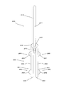
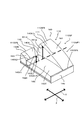
- the cleaning tool A includes a cleaning body holder 200 and a cleaning body 100.
- the cleaning body holder 200 is detachably attached to the cleaning body 100 and is configured to hold the cleaning body 100.
- This cleaning tool A is an example of the “cleaning tool” in the present invention.
- This cleaning body holder 200 is an example of the “holder” in the present invention.
- This cleaning body 100 is an example of the “cleaning sheet” in the present invention.
- the cleaning body 100 is configured to extend in both the longitudinal direction Y and the longitudinal intersecting direction X defined by the direction intersecting the longitudinal direction Y.
- the longitudinal direction Y is defined by a direction parallel to the direction in which the cleaning body holder 200 is inserted into the cleaning body 100.
- the direction in which the cleaning body holder 200 is inserted into the cleaning body 100 is the insertion direction Y1.
- the direction opposite to the insertion direction Y1 is the drawing direction Y2.
- a direction intersecting with each of the longitudinal direction Y and the longitudinal crossing direction X is a thickness direction Z.
- “intersection” means “orthogonal”.
- This longitudinal direction Y is an example of the “longitudinal direction” in the present invention.
- This longitudinal cross direction X is an example of the “longitudinal cross direction” in the present invention.
- This thickness direction Z is an example of the “thickness direction” in the present invention.
- a point that is the center of the longitudinal cross direction X is defined as a longitudinal cross direction center point XCP.
- the longitudinal cross direction X for forming the longitudinal cross direction center point XCP can be appropriately selected from the longitudinal cross directions X at arbitrary locations on the cleaning body 100.
- a straight line passing through the longitudinal cross-direction center point XCP and parallel to the longitudinal direction Y is defined as a longitudinal center line YCL.
- the direction from the longitudinal crossing direction center point XCP to the region where the cleaning body 100 does not exist is defined as the outer direction 100D1. Furthermore, a direction from the region where the cleaning body 100 does not exist to the longitudinal cross direction center point XCP is defined as an inner direction 100D2.
- the cleaning body holder 200 is mainly composed of a handle part 210 and a cleaning body holding part 220.
- the handle part 210 is a member that is formed in a long shape and is held by the user during cleaning.
- the handle part 210 has a handle 211 and a handle joint part 212.
- the handle joint portion 212 is joined to the connecting portion 230 of the cleaning body holding portion 220.
- the handle 211 is formed in a long shape extending from the handle joint portion 212.
- the handle portion 210 is an example of the “gripping portion” in the present invention.
- the cleaning body holding unit 220 is an example of the “holding unit” in the present invention.
- the cleaning body holding part 220 is formed of a resin material and is a member for holding the cleaning body 100.
- the cleaning body holding part 220 is mainly composed of two holding members 221 formed in a long shape, a convex part 260, a pressing plate 270, and the like.
- the cleaning body holder 220 is made of polypropylene (PP).
- maintenance part 220 can select the resin material which has flexibility suitably.
- polyethylene (PE), polyethylene terephthalate (PET), acrylonitrile-butadiene-styrene resin (ABS), and polyester-based thermoplastic elastomer can be used.
- the holding member 221 extends from the connecting portion 230 in a direction opposite to the direction in which the handle 211 extends. That is, the holding member 221 includes a connecting portion 230, a tip portion 240, and an intermediate portion 250 that extends from the connecting portion 230 toward the tip portion 240.
- the front end portions 240 of the two holding members 221 are free ends.
- the convex portion 260 is provided in the outer direction 100D1 in the intermediate portion 250.
- the convex portion 260 includes a first convex portion 261 provided on the connecting portion 230 side and a second convex portion 262 provided on the distal end portion 240 side.
- the pressing plate 270 is formed so as to protrude from the connecting portion 230.
- the holding plate 270 is formed between the pair of holding members 221 so as to extend in parallel with the holding member 221.
- the presser plate 270 is configured as a plate-like member that is curved so as to be convex downward, and further includes a locking projection (not shown) on the lower surface.
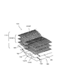
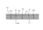
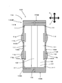
- the cleaning body 100 is a sheet-like cleaning body having a dirt collecting function for collecting dirt such as dust to be cleaned. As shown in FIGS. 4 and 7, the cleaning body 100 is formed in a rectangular shape in plan view.
- This cleaning body 100 is a disposable type that is used once as a guide, or a disposable type that is replaced with multiple uses as a guide while holding dust and dust removed from the surface to be cleaned. It may be of a type that can be used repeatedly after washing or the like.
- the base 120 is formed by the first sheet body 121.
- the base 120 has an end 120A on the longitudinal cross direction X, an end 120B on the longitudinal direction Y, one surface 120C, and the other surface 120D.
- the base 120, the first sheet body 121, the one surface 120C, and the other surface 120D are respectively the “base”, “first sheet body”, “one side”, and “the other side” in the present invention. It is an example.
- the fiber assembly 110GF is disposed on one surface 120C of the base 120.
- a second sheet body 122 is disposed on the other surface 120D of the base 120.
- These laminated base 120, fiber assembly 110 ⁇ / b> GF, and second sheet body 122 all extend in the longitudinal direction Y in the cleaning body 100.
- the fiber aggregate 110GF forms a brush part 110 having a dirt collecting function.
- This fiber assembly 110GF is an example of the “fiber assembly” according to the present invention.
- the brush portion 110 is an example of the “brush portion” in the present invention. Note that, as in the cleaning body 100 according to this embodiment, the fiber assembly 110GF disposed on the one surface 120C side of the base 120 is referred to as a first fiber assembly 110GF1.
- the fiber aggregate 110GF is formed by an aggregate of fibers 110SF.
- the fiber 110SF is a single fiber structure composed of typical fibers, or a fiber structure in which typical fibers are aligned in the length direction and / or radial direction (twisted yarn, spun yarn, a plurality of long lengths). A thread material in which fibers are partially connected), or an aggregate of the fiber structure.
- the “typical fiber” is a structural unit such as a yarn or a woven fabric, and has a length that is sufficiently long compared to the thickness, and is in a thin and flexible form.
- long continuous fibers are long fibers (filaments), and short fibers are short fibers (staples).
- the fibers 110SF partially include thermoplastic fibers, and each fiber 110SF can be fused (also referred to as “welding”).
- the fiber aggregate 110GF is formed by a plurality of fibers 110SF arranged in parallel in a predetermined fiber orientation direction 110D and stacked in the thickness direction Z.
- the fiber orientation direction 110D substantially coincides with the longitudinal cross direction X.
- the fiber orientation direction 110D of the fiber 110SF indicates the fiber orientation in the product design.
- the fiber 110SF of the fiber assembly 110GF has a connection end portion 110SFA that is an end portion to be welded to the central joint 140.
- the fiber 110SF has an open end 110SFB that is an end opposite to the connection end 110SFA.
- the open end 110SFB is a free end.
- the connection end 110SFA is an example of the “connection end” according to the present invention.
- the open end portion 110SFB is an example of the “open end portion” according to the present invention.
- the fiber assembly 110GF is formed by laminating three fiber layers, but the number of fiber layers may be one or more as necessary.
- the fiber assembly 110GF preferably has a planar structure with a predetermined plane or curved surface, and is configured as a three-dimensional shape having a certain thickness or a thin sheet shape.
- the fiber aggregate 110GF is typically made of polyethylene (PE), polypropylene (PP), polyethylene terephthalate (PET), nylon, rayon, etc., and is practically a long fiber (filament) obtained by opening the tow. ) Is preferably used.
- the core portion is preferably made of polypropylene (PP) or polyethylene terephthalate (PET), and the sheath portion covering the outer surface of the core portion is preferably composed of a composite fiber of polyethylene (PE) to form the fiber assembly 110GF.
- the fineness 110SF of the fibers forming the fiber aggregate 110GF is preferably 1 to 50 dtex, more preferably 2 to 10 dtex.
- each fiber assembly may be composed of fibers having substantially the same fineness, or each fiber assembly may include fibers having different finenesses.
- an oil agent is supplied to the fiber assembly 110GF.
- This oil agent is mainly composed of liquid paraffin.
- the fiber assembly 110GF includes crimped fibers.
- a crimped fiber here is comprised as a fiber to which the well-known crimping process was provided, and is set as the structure where fibers are easy to get entangled.
- the fiber assembly 110GF is bulkier than the state before the cleaning body holder 200 is mounted, and a structure in which dust is easily taken into the crimped portion.
- This structure can be realized in particular by using crimped fibers formed from tow fibers.
- the fibers 110SF of the fiber assembly 110GF constituting the brush portion 110 have the same length in the longitudinal cross direction X.
- the crimped state between the individual crimped fibers does not necessarily match. Therefore, when the lengths of the individual fibers 110SF are compared, they may not be completely the same length. Therefore, the “same length” according to the present invention merely means “same design length”. Here, “same design length” will be described.
- the cleaning body 100 is formed by cutting, in a manufacturing process described later, stacked materials that are continuous in the machine direction M in two predetermined regions in a direction that intersects the machine direction M.
- the direction in which the two predetermined regions are cut is linear, and when they are parallel to each other, “the same design length”.
- the “straight line” does not necessarily indicate a “perfect straight line”. For example, even if it is curved due to design reasons or the like, it is sufficient if it is substantially “straight line”.
- the second sheet body 122 is a sheet formed of a rectangular nonwoven fabric shorter than the base 120 in the longitudinal direction Y.
- the nonwoven fabric which comprises the base 120 (1st sheet body 121) and the 2nd sheet body 122 all typically the sheet-like nonwoven fabric which consists of a thermomeltable fiber (thermoplastic fiber) is used. That is, the base 120 and the second sheet body 122 are also referred to as “nonwoven fabric sheets”.
- nonwoven fabric sheets in order to improve the sweeping-out function at the time of cleaning, it is preferable to use a highly rigid nonwoven fabric.
- synthetic fibers such as polyethylene (PE), polypropylene (PP), and polyethylene terephthalate (PET), are used for this nonwoven fabric.
- nonwoven fabric As a form of a nonwoven fabric, what was formed by the air through method or the spun bond method is used. On the other hand, even if it is other than a nonwoven fabric, a cloth or a film body made of a synthetic resin can be used.
- the base 120 and the second sheet body 122 include a central joint 140 that extends along the longitudinal center line YCL of the cleaning body 100 and a plurality of first joints 141 that are located on both sides of the central joint 140.
- a central joint 140 that extends along the longitudinal center line YCL of the cleaning body 100 and a plurality of first joints 141 that are located on both sides of the central joint 140.
- the base 120, the second sheet body 122, and the fiber assembly 110 ⁇ / b> GF are welded and joined at the central joint 140.
- the base 120, the second sheet body 122, and a part of the fiber aggregate 110 ⁇ / b> GF are welded and joined at the first joint 141.
- the 1st junction part 141 located in the both ends side in the longitudinal direction Y is formed in the position where the 2nd sheet
- a pair of holding spaces 130 extending in the longitudinal direction Y are formed between the base 120 and the second sheet body 122 in a region sandwiched between the central joint 140 and the first joint 141. Yes.
- openings 131 are formed at both ends of the holding space 130 in the longitudinal direction Y, respectively.
- the holding space 130 is an example of the “insertion portion” in the present invention.
- the holding space 130 is formed by a predetermined region of the base 120 between the pair of first joining portions 141 in the longitudinal cross direction X and a predetermined region of the second sheet body 122.
- a plurality of first joint portions 141 are continuously formed substantially along the longitudinal direction Y.
- the first welded joints 141 adjacent in the longitudinal direction Y do not necessarily need to be arranged in the longitudinal direction Y.
- the arrangement form of the first welding joint portion 141 can be appropriately designed depending on the design property and the shape of the cleaning body holding portion 220. At this time, of course, the first weld joint 141 can be formed in a continuous line shape.
- a lateral joint 140A is provided in a predetermined region between the end 120A of the base 120 in the longitudinal cross direction X and the central joint 140.
- the lateral joint 140A is provided between 120A on the longitudinal cross direction X of the base 120 and the first weld joint 141.
- the side joints 140A are provided at two positions with a gap in the direction parallel to the longitudinal direction Y.
- the side joint portions 140A are paired in the longitudinal cross direction X.
- the side joint 140A joins the base 120, the second sheet 122, and the fiber assembly 110GF. Note that the side joints 140A do not have to be two in the longitudinal direction Y, and may be single or plural. Further, it is not necessary to be parallel to the longitudinal direction Y.
- This lateral joint 140A is an example of the “second fiber joint” according to the present invention.
- the central joint 140, the first joint 141, and the side joint 140A described above are formed by welding with heat.
- the joint portion according to the present invention can also be formed by an adhesive such as ultrasonic welding, sewing, or a hot melt adhesive.
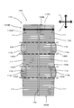
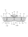
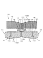
- the brush part 110 has a first brush region 111 and a second brush region 112.
- the second brush region 112 has a protruding region 112 ⁇ / b> L configured to be longer than the first brush region 111.
- the first brush region 111 is formed of the fibers 110SF that are not joined by the side joining portion 140A in the longitudinal cross direction X.
- the second brush region 112 is formed of fibers joined in the longitudinal cross direction X by the side joining portion 140A.
- the second brush region 112 is formed longer than the first brush region 111.
- “long” will be described with reference to FIG.
- the longest straight line among the straight lines connecting the longitudinal center line YCL and the end portion 111B in the longitudinal cross direction X in the first brush region 111 is defined as a first brush region length 111D.
- the longest straight line among the straight lines connecting the longitudinal center line YCL and the end portion 112B on the longitudinal cross direction X in the second brush region 112 is defined as a second brush region length 112D.
- the second brush region 112 being longer than the first brush region 111 means that the second brush region length 112D is longer than the first brush region length 111D.
- region 112 which is an area
- the fiber 110SF is flexible. Therefore, when used by the user, the shape of the fiber 110SF changes. As a result, there may be a case where the relationship that the second brush region length 112D is longer than the first brush region length 111D is not established.
- the protruding region 112L exhibits a predetermined action and effect. Therefore, the relationship between the first fiber length 111D and the second fiber length 112 described above is determined immediately after the cleaning body 100 is manufactured, immediately after the user purchases the product and takes out the cleaning body 100, or the user. However, when the cleaning body 100 is used, it is sufficient to form it immediately after the cleaning body 100 itself is greatly swung to increase the distance between the fibers 110SF to make it bulky.
- the first brush region 111 is provided at the end portion 100B in the longitudinal direction Y. Moreover, the 1st brush area
- the second brush region 112 may be provided at the end portion 100B in the longitudinal direction Y, and the first brush region 111 and the second brush region 112 are formed one by one. The configuration may be different.
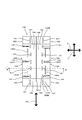
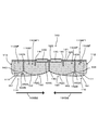
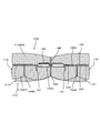
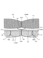
- the brush part 110 has a contact area 160 that contacts the cleaning target. Based on FIG. 6, the contact area 160 will be described.
- the contact area 160 includes a first contact area 161, a second contact area 162, and a third contact area 163.
- the first contact region 161 is formed in the first brush region 111.
- the second contact region 162 is formed between the central joint 140 and the side joint 140A in the second brush region 112.
- the third brush region 163 is formed between the side joint 140A and the open end portion 110SFB in the second brush region 112.
- the contact area 160 is an example of the “contact area” according to the present invention.
- the first contact area 161 is an example of the “first contact area” according to the present invention.
- the second contact area 162 is an example of the “second contact area” according to the present invention.
- This third contact area is an example of the “third contact area” according to the present invention.
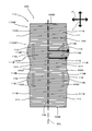
- the second contact region 162 has a lower region 162A formed lower than the first contact region 161 in the thickness direction Z.
- the lower region 162 ⁇ / b> A is a guide region 162 ⁇ / b> B that can guide the dust to be cleaned to the adjacent first contact region 161.
- This lower region 162A is an example of the “lower region” according to the present invention.
- the guidance area 162B is an example of the “guidance area” according to the present invention.
- the lower region 162A and the guide region 162B are formed as a region including the side joint 140A that is a boundary between the second contact region 162 and the third contact region 163. Therefore, it can be said that the lower region 162A and the guide region 162B are formed in the third contact region 163.
- the lower region 162A and the guide region 162B are formed between the second contact region 162 and the third contact region 163.
- the lower region 162A and the guide region 162B will be mainly described as being provided in the second contact region 162.
- 140 A of side junction parts have contact
- region 140A2 which is an area
- the shortest length in the thickness direction Z between the contact facing region 140A1 and the contact region 140A2 is defined as a second contact region height 162Z.
- a point on the contact facing area 140A1 of the side joint 140 at the point where the second contact area height 162Z is obtained is set as a height measurement point 140A1P.
- a straight line passing through the height measurement point 140A1P and parallel to the longitudinal direction Y is defined as a height measurement straight line 161Y.
- the longest length is defined as a first contact region height 161Z. That is, in the thickness direction Z, the second contact region 162 is “lower” than the first contact region 161.
- the second contact region height 162 Z is the first contact region height. It means “shorter” than 161Z.
- the fiber 110SF is flexible. Therefore, when used by the user, the shape of the fiber 110SF changes. As a result, there may be a case where the second contact area height 162Z does not establish a relationship of “shorter” than the first contact area height 161Z.
- the lower region 162A exhibits a predetermined action and effect when the user uses the cleaning tool A. Therefore, the relationship between the first contact area height 161Z and the second contact area height 162Z described above is that immediately after the cleaning body 100 is manufactured or the user purchases the product and takes out the cleaning body 100. Immediately after the user uses the cleaning body 100, the cleaning body 100 itself is greatly shaken to increase the distance between the fibers 110SF to make it bulky.
- the lower region A162 becomes a region including the contact side region 140A2 of the side joint 140A.
- the guidance region 162B is a region parallel to the longitudinal direction Y in the lower region 162A. When the guide region 162B is extended, the guide region 162B comes into contact with the side portion of the first contact region 161. Therefore, the dust to be cleaned that has passed through the guidance area 162B is easily captured by the side area 161A of the first contact area 161.
- Both ends of the fiber 110SF forming the second contact region 162 are fixed by the center joint 140 and the side joint 140A. Therefore, the fiber 110SF constituting the second contact region 162 has a narrower movable width than the fiber 110SF forming the first contact region 161 and the fiber 110SF forming the third contact region 163. Is. Therefore, when the user uses the cleaning tool A, for example, resistance can be applied to dust that is strongly adhered to the object to be cleaned. Therefore, the second contact region 162 is a resistance region 162C that can apply resistance to the dust to be cleaned.
- the cleaning body 110 has a strip piece 150.
- the strip 150 is formed on the longitudinal crossing method X on the first strip 151 formed between a plurality of cut lines provided at the end of the base 120 in the longitudinal crossing direction X and the second sheet body 122.
- a second strip piece 152 formed between a plurality of cut lines provided at the end of the second strip piece 152.
- the cut lines in the base 120 and the second sheet body 122 have a zigzag shape.
- the strip 150 may be either the first strip 151 or the second strip 152.
- each holding member 221 can be inserted into the holding space 130.
- the cleaning body 100 is held by the cleaning body holder 200 by the holding member 221 being inserted into the holding space 130 along the insertion direction Y1.
- the cleaning body holder 200 is pulled out from the holding space 130 along the pulling direction Y2.
- the convex portion 260 is disposed between the adjacent first joint portions 141. Thereby, the engagement state of the cleaning body holder 200 and the cleaning body 100 is reliably maintained.
- the holding plate 270 holds the second sheet body 122 together with the holding member 221.
- dust that has not been captured in the second contact region 162 or the third contact region is captured in the side region 161A of the first contact region 161.
- the fiber 110SG is flexible, when the cleaning body 100 is pressed against the floor F with a strong pressure, the lower region 162A and the guide region 162B may be crushed.
- the cleaning tool A is used within the range in which the lower region 162A and the guide region 162 are formed, the present invention is configured as long as dust can be captured.
- the protruding area L can improve the dust scraping operation. Further, the lower region 162A and the guiding region 162B can increase the chance that dust is captured by the fiber assembly 110GF. Moreover, the dust attached to the cleaning target can be separated from the cleaning target by the resistance region 162C.
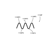
- FIG. 12 shows a fiber 110SF that forms the fiber assembly 110.
- the fiber 110SF according to FIG. 12 shows a stationary state where no external force is applied. Since the fiber 110SF is a crimped fiber, it has a plurality of bent portions 110SFC and has a zigzag shape. The bent portion 110SFC is also called a crimp portion.
- the fiber 110SF can be expanded and contracted by having the bent portion 110SFC.
- FIG. 13 shows a state in which an external force (tension) is applied in opposite directions to both ends of the stationary fiber 110SF.
- the fibers 110SF can be extended by separating the distance between the bent portions 110SF.
- the fiber 110SF returns from the extended state shown in FIG. 13 to the stationary state shown in FIG.
- the base 120 and the fiber assembly 110GF have different elastic elastic modulus. That is, the stretch elastic modulus of the fiber assembly 110GF is higher than the stretch elastic modulus of the base 120. Specifically, the stretch elastic modulus of the fiber assembly 110GF is 75.7%, and the stretch elastic modulus of the base 120 is 56.0%.
- the measurement of elastic modulus it carried out by the following test. (1) A test piece of the fiber assembly 110GF and a test piece of the base 120 are prepared. The test piece has a length of 500 mm.
- the fiber assembly 110GF used was a tow fiber formed of a core-sheath composite fiber in which polyethylene (PE) was a sheath material and polyethylene terephthalate (PET) was a core material.
- This tow fiber has a fineness of 3.5 dtex for one fiber.
- the fineness of the entire fiber assembly is 110,000 dtex.
- the base 120 used the spunbonded nonwoven fabric formed by the core-sheath composite fiber whose polyethylene (PE) is a sheath material and polyethylene terephthalate (PET) is a core material.
- This nonwoven fabric has a basis weight of 20 g / m2. The width was 190 mm.
- a mark indicating the start and end of a predetermined length is attached in the longitudinal direction of the test piece. This mark indicates a length of 200 mm. The length between the start end and the end end in this state is L0. L0 is 200 mm. (2) Fix the upper end of the test piece with a clip.
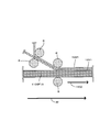
- FIG. 14 is a flowchart showing the manufacturing process.
- the manufacturing process includes a first step S11 that is a step of laminating the base 120, the second sheet, and a material that becomes a part of the fiber assembly 110GF, and a step of joining the materials laminated in the first step S11.
- a fourth step S14 which is a step to be performed, a fifth step S15 which is a step of cutting the material joined in S14 into a predetermined shape, and a step of forming the first brush region 111 and the second brush region 112.
- the cleaning body 100 which concerns on embodiment of this invention has the strip piece 150. FIG. On the other hand, for the convenience of explanation, it is omitted in the manufacturing process of the strip piece 150.
- FIG. 15 shows the first step S11.
- a first sheet material 1211 for forming the first sheet body 121 to be the base 120, a second sheet material 1221 for forming the second sheet body 122, A first fiber assembly material 110GF1A for forming a part of one fiber assembly 110GF1 is supplied.
- the first fiber aggregate material 110GF1A is disposed on one side of the first sheet material 1211.
- the second sheet material 1221 is disposed on the other side of the first sheet material 121.
- each material is supported by the support roll R and is transferred in the machine direction M by a drive mechanism (not shown).
- the fiber orientation direction 110D of the first fiber assembly material 110GF1A approximately matches the machine direction M.
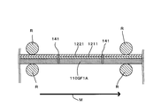
- FIG. 16 shows the second step S12.
- all layers of the second sheet material 1221, the first sheet material 1211, and the first fiber assembly material 110GF1 are welded.
- two portions of the predetermined region in the second sheet material 1221, the first sheet material 1211, and the first fiber assembly material 110GF1 are welded.
- the welded portions form a pair of first joint portions 141.
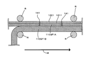
- FIG. 17 shows the third step S13.
- the second fiber assembly material 110GF1B is supplied.
- the second fiber assembly material 110GF1B is supplied to the side of the first fiber assembly material 110GF1A where the first sheet material 1211 is not disposed. Note that the fiber orientation direction 110D of the second fiber assembly material 110GF1B approximately matches the machine direction M.
- FIG. 18 shows a fourth step S14.
- the fourth step S14 all layers of the second sheet material 1221, the first sheet material 1211, the first fiber assembly material 110GF1A, and the second fiber assembly material 110GF1B are joined by thermal welding. .
- a central joint 140 and a side joint 140A are formed.
- the central joint 140 all of the predetermined regions that cross the fiber orientation direction 110D in the first fiber assembly 110GF1 are joined.
- the side joint 140A a part of a predetermined region crossing the fiber orientation direction 110D in the first fiber assembly 110GF1 is joined.
- the lateral joint 140A is welded at two locations in a direction crossing the fiber orientation direction 110D.
- the central joint 140 and the side joint 140A can be provided by a single joining device. In this case, the center joint 140 and the side joint 140A are formed almost simultaneously.
- the joining device that forms the central joint 140 and the joining device that joins the side joint 140A may be independent joint devices.
- the side joint 140A can be provided after the central joint 140 is provided.
- the central joint 140 can be provided after the side joint 140A is provided.
- a predetermined tension is applied to the first fiber assembly material 110GF1A over the first step S11 to the fourth step S14.
- a specific tension is 40N.
- the predetermined tension applied to the first fiber assembly material 110GF1A and the second fiber assembly material 110GF1B is applied to stabilize the shape for easy manufacture. Further, this tension is applied to shrink the fibers 110SF of the fiber assembly material 110GF and form the first brush region 111 and the second brush region 112 in the manufacturing process described later. Note that tension is also applied to the first sheet material 1211 and the second sheet material 1221 in order to stabilize the shape.
- FIG. 19 shows the fifth step S15.
- the second sheet material 1221, the first sheet material 1211, the first fiber assembly material 110GF1A, and the second fiber assembly material 110GF1B are cut at predetermined regions.
- the second sheet material 1221, the first sheet material 1211, the first fiber aggregate material 110GF1A, and the second fiber aggregate material 110GF1B are released from the tension.
- FIG. 20 shows a sixth step S16.
- the fiber 110SF corresponding to the first fiber assembly material 110GF1A released from the tension contracts toward the inner direction 100D2 in the longitudinal cross direction X.
- the fibers connected to both the center joint 140 and the side joint 140 A are also connected to the first sheet body 121 and the second sheet body 122. Therefore, the contraction of the fiber 110SF is limited by the first sheet body 121 and the second sheet body 122.
- the fiber 110SF joined only to the central joint 140 contracts significantly compared to the fiber 110SF connected to the first sheet body 121 and the second sheet body 122.
- the fiber 110SF joined only to the central joint 140 forms the first brush region 111.
- the fibers 110SF joined to the center joint 140 and the side joint 140A form the second brush region 112.
- the cleaning body 100 of the cleaning tool A according to the present invention is manufactured.
- the present invention is not limited to the above-described embodiment and manufacturing method, and various applications and modifications are possible.
- two holding members 211 of the holder 200 are formed, and two holding spaces 130 of the cleaning body 100 are also formed correspondingly.
- a single holding space 130 may be provided for the two holding members 211.
- a single holding space 130 can be provided for a single holding member 211.
- the cleaning body 101 which concerns on a 1st modification differs in the structure of the holding
- the central joint 140 can join only the brush part 110.
- the brush part 110 and the base part 120 can be joined by an adhesive (not shown) or the like.
- the first brush region 111 and the second brush region 112 are formed, and thus the same operation and effect as the cleaning body 100 in the above-described embodiment. Play.
- the cleaning body 102 which concerns on a 2nd modification differs in the structure of the holding
- a holding space 130 that is a space extending in the longitudinal direction Y can be formed between the third sheet 123 and the fourth sheet 124.
- the central joint 140 joins only the brush part 110 and the base 120.
- the third sheet 123 is joined to the base 120 with an adhesive or the like to form a fifth joint 145.
- the first brush region 111 and the second brush region 112 are formed, and thus the same operation and effect as the cleaning body 100 in the above-described embodiment. Play.
- the cleaning body 103 according to the third modification is different in the configuration of the holding space 130 from the cleaning body 100 in the above-described embodiment. That is, the holding space 130 of the cleaning body 103 according to the third modification is formed independently of the base 120. That is, predetermined surfaces of the fifth sheet body 125 are brought into contact with each other to form the joining sheet region 125A. A predetermined region in the bonding sheet region 125A is welded to form a sixth bonding portion 146. Thereby, the holding space 130 which is a space extending in the longitudinal direction Y can be formed.
- the central joint 140 joins only the brush part 110 and the base 120.
- the fifth sheet 125 is bonded to the base 120 with an adhesive or the like to form a seventh bonded portion 147. Even in the cleaning body 103 according to the third modified example, the first brush region 111 and the second brush region 112 are formed, and thus the same operation and effect as the cleaning body 100 in the above-described embodiment. Play.
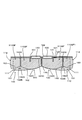
- the cleaning body 104 according to the fourth modified example includes the brush portion 110 not only on the one surface 120C side of the base 120 but also on the other surface 120D side as compared with the cleaning body 100 in the above-described embodiment. Is formed. That is, the second fiber aggregate 110GF2 is welded by a predetermined region in a direction crossing the fiber orientation direction 110D. By this welding, an eighth joint 148 is formed. Then, the second fiber assembly 110GF2 is joined to the second sheet body 122 of the cleaning body 100 in the embodiment by an adhesive or the like. A ninth weld is formed by this joining. In this way, the cleaning body 104 is formed.
- the second fiber assembly 110GF2 includes a first brush region 111 and a second brush region 112.
- the protruding region L, the lower region 162A, the guidance region 162B, and the resistance region 162C Of course, can be formed.
- the cleaning body 105 according to the fifth modification is not limited to the one surface 120C side of the base 120 but also the other surface 120D side as compared with the cleaning body 101 in the first modification described above.
- the part 110 is formed. That is, the second fiber assembly 110GF2 is joined to the first sheet body 121 forming the holding space 130.
- the second fiber assembly 110GF2 is welded in the central region. The weld location in this central region forms a tenth joint 1410.
- the second fiber assembly 110GF2 having the tenth joint 141 is joined to the first sheet body 121 forming the holding space 130 by an adhesive (not shown) or the like. In this way, the cleaning body 105 is formed.
- the second fiber assembly 110GF2 includes a first brush region 111 and a second brush region 112.
- the protruding region L, the lower region 162A, the guidance region 162B, and the resistance region 162C Of course, can be formed.
- the cleaning body 106 according to the sixth modification is not limited to the one surface 120C side of the base 120 but also the other surface 120D side as compared with the cleaning body 102 according to the second modification described above.
- the part 110 is formed. That is, the second fiber assembly 110GF2 and the sixth sheet body 126 are welded in the central region to form the eleventh joint 1411. Then, the surface of the sixth sheet body 126 on which the second fiber aggregate 110GF2 is not disposed and the fourth sheet body 124 are joined together with an adhesive or the like to form a twelfth joining portion 1412. In this way, the cleaning body 106 is formed.
- the second fiber assembly 110GF2 includes a first brush region 111 and a second brush region 112.
- the protruding region L, the lower region 162A, the guidance region 162B, and the resistance region 162C Of course, can be formed.
- the cleaning body 107 according to the seventh modification is not limited to the one surface 120C side of the base 120 but also the other surface 120D side, as compared with the cleaning body 103 according to the third modification described above.
- the part 110 is formed. That is, the second fiber assembly 110GF2 and the seventh sheet body 127 are welded in the central region to form the thirteenth joint portion 1413. Then, the surface of the seventh sheet body 127 on which the fiber assembly 110 is not disposed and the fifth sheet body 125 are bonded together with an adhesive or the like to form a fourteenth bonded portion 1414. In this way, the cleaning body 107 is formed.
- the second fiber assembly 110GF2 includes a first brush region 111 and a second brush region 112.
- the protruding region L, the lower region 162A, the guidance region 162B, and the resistance region 162C Of course, can be formed.
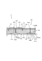
- the second brush region 112 is provided at the end portion 108B in the longitudinal direction Y of the cleaning body 108 as compared with the cleaning body 100 in the above-described embodiment. It is what. Even in the cleaning body 108 according to the eighth modified example, the first brush region 111 and the second brush region 112 are formed, and thus the same operation and effect as the cleaning body 100 in the above-described embodiment. Play.
- a ninth modification will be described based on FIG.
- the lengths of the brush portion 110 and the base portion 120 are different from those of the cleaning body 100 in the above-described embodiment. That is, in the longitudinal direction Y, the brush portion 110 is formed longer than the base portion 120. Further, in the longitudinal cross direction X, the brush portion 110 is longer than the base portion 120.
- Such a configuration can be achieved by a cleaning body having a structure like the cleaning body 101 according to the first modification shown in FIG. 21, for example. That is, the brush part 110 and the holding space 130 are formed independently. At this time, the size of the base 120 forming the holding space 130 is set to an arbitrary size.
- the cleaning body 109 according to the ninth modification is formed.
- the first brush region 111 and the second brush region 112 are formed, and thus the same operation and effect as the cleaning body 100 in the above-described embodiment. Play.
- the first brush region 111 is formed at the end 109 ⁇ / b> A in the longitudinal crossing direction X of the cleaning body 109.
- the second brush region 112 is formed at the end 109 ⁇ / b> A in the longitudinal crossing direction X of the cleaning body 109. Therefore, when the end 109A of the cleaning body 109 in the longitudinal cross direction X is brought into contact with the object to be cleaned, the dust trapping effect can be improved.
- the cleaning tool A is an example of the “cleaning tool” according to the present invention.
- the cleaning bodies 100, 101, and 102 are examples of the “cleaning sheet” according to the present invention.
- the cleaning body holder 200 is an example of the “holding tool” according to the present invention.
- the longitudinal direction Y is an example of the “longitudinal direction” according to the present invention.
- the longitudinal cross direction X is an example of the “longitudinal cross direction” according to the present invention.
- the thickness direction Z is an example of the “thickness direction” according to the present invention.
- the cleaning body holding unit 220 is an example embodiment that corresponds to the “holding unit” according to the present invention.
- the handle part 210 is an example embodiment that corresponds to the “gripping part” according to the present invention.
- the end portion 100B is an example of the “end portion in the longitudinal direction” according to the present invention.
- the end portion 100A is an example of the “end portion in the longitudinal cross direction” according to the present invention.
- the brush portion 110 is an example of a “brush portion” according to the present invention.
- the base 120 is an example of the “base” according to the present invention.
- the holding space 130 is an example of the “insertion portion” according to the present invention.
- the fiber orientation direction 110D is an example of the “fiber orientation direction” according to the present invention.
- the fiber assembly 110GF is an example of the “fiber assembly” according to the present invention.
- the contact area 160 is an example of the “contact area” according to the present invention.
- the first contact area 161 is an example of the “first contact area” according to the present invention.
- the second contact area 162 is an example of the “second contact area” according to the present invention.
- the lower region 162A is an example of the “lower region” according to the present invention.
- the guidance area 162B is an example embodiment that corresponds to the “guidance area” according to the present invention.
- the central joint 140 is an example of the “first fiber joint” according to the present invention.
- the side joint 140A is an example of the “second fiber joint” according to the present invention.
- the connection end 110SFA is an example of the “connection end” according to the present invention.
- the open end portion 110SFB is an example of the “open end portion” according to the present invention.
- the third contact area 163 is an example of the “third contact area” according to the present invention.
- the first sheet 121 is an example of the “first sheet body” according to the present invention.
- the second sheet body 122 is an example embodiment that corresponds to the “second sheet body” according to the present invention.
- the third sheet body 123 is an example of the “third sheet body” according to the present invention.
- the fourth sheet body 124 is an example of the “fourth sheet body” according to the present invention.
- the fifth sheet body 125 is an example embodiment that corresponds to the “fifth sheet body” according to the present invention.
- the sixth sheet body 126 is an example embodiment that corresponds to the “sixth sheet body” according to the present invention.
- One surface 120A is an example of "one side” according to the present invention.
- the other surface 120D is an example of the “other side” according to the present invention.
- the cleaning tool according to the present invention can be configured as follows.
- (Aspect 1) In a cleaning tool having a cleaning sheet and a holder for holding the cleaning sheet,
- the cleaning sheet includes a longitudinal direction defined by a direction in which the holder is inserted into the cleaning sheet, a longitudinal cross direction defined by a direction intersecting the longitudinal direction, and both the longitudinal direction and the longitudinal cross direction. Configured to extend in the thickness direction defined by the direction intersecting
- the holder has a holding part for holding the cleaning sheet, and a holding part that is connected to the holding part and is held by a user.
- the cleaning sheet includes an end portion in the longitudinal direction, an end portion in the longitudinal cross direction, a brush portion configured to be able to clean an object to be cleaned, a base portion to which the brush portion is connected, and a base portion Formed and having an insertion part into which the holding part is inserted,
- the brush portion includes a fiber assembly that is an assembly of a plurality of fibers having a predetermined fiber orientation direction, a contact region that contacts the cleaning target, and a first contact region formed in the contact region.
- a second contact area, The second contact region has a lower region formed lower than the first contact region in the thickness direction,
- the low level region is a guide region capable of guiding the dust to be cleaned to the adjacent first contact region.
- the brush portion includes a first fiber joint portion that joins fibers in the fiber assembly in all predetermined regions in a direction crossing the fiber orientation direction, and a predetermined region in a direction transverse to the fiber orientation direction.
- a second fiber bonding portion for bonding the fibers in the fiber assembly;
- the fiber has a connection end connected to the first fiber joint, and a release end that is an end opposite to the connection end.
- the first contact region is formed between the first fiber joint and the open end of the fiber
- the cleaning tool wherein the second contact region is formed between the first fiber joint and the second fiber joint.
- a cleaning tool according to aspect 2 A cleaning tool, wherein a third contact region is formed between the second contact region and the open end of the fiber.
Abstract
Description
この特開2007-137566号に記載された清掃用物品の長手交差方向上の端部は、ジグザク状に形成されている。 Japanese Patent Application Laid-Open No. 2007-137466 describes a handle insertion part and a cleaning article provided with a fiber layer and a scraping sheet above and below the handle insertion part. The handle insertion portion is formed by a pair of handle mounting sheets. This cleaning article is used by being attached to a handle.
The end of the cleaning article described in JP-A-2007-137666 in the longitudinal cross direction is formed in a zigzag shape.
そこで、本発明は上記に鑑み、清掃効果の高い清掃具を提供することを目的とする。 The cleaning article described in Japanese Patent Application Laid-Open No. 2007-137666 has a zigzag end in the longitudinal cross direction. Therefore, the fiber lengths of the fiber layers in the longitudinal cross direction were different. That is, there is a fear that the cleaning effect is low in the portion where the cleaning length of the fiber layer is short.
In view of the above, an object of the present invention is to provide a cleaning tool having a high cleaning effect.
以下、本発明の実施形態について、図1~図10を参照しつつ詳細に説明する。まず、本発明における「清掃具」の一実施の形態である清掃用具Aの構成につき説明する。この清掃用具Aを用いて清掃される清掃対象としては、一戸建て、マンション、ビル、工場、車両などの室内、室外、屋外における被清掃面(床面、壁面、窓、天井面、外壁面、家具面、衣類、カーテン、寝具、照明、家電品など)や、人体の各構成部位における被清掃面などが挙げられる。これら各種の被清掃面は、平面として構成されてもよいし、或いは曲面、凹凸面、段差面として構成されてもよい。 (Outline of cleaning tools)
Hereinafter, embodiments of the present invention will be described in detail with reference to FIGS. First, the configuration of the cleaning tool A which is an embodiment of the “cleaning tool” in the present invention will be described. The cleaning objects to be cleaned using this cleaning tool A include indoor, outdoor, and outdoor surfaces to be cleaned (floor surface, wall surface, window, ceiling surface, outer wall surface, furniture, etc.) Surface, clothes, curtains, bedding, lighting, home appliances, etc.) and surfaces to be cleaned in each component of the human body. These various surfaces to be cleaned may be configured as a flat surface, or may be configured as a curved surface, an uneven surface, or a step surface.
長手方向Yおよび長手交差方向Xのそれぞれと交差する方向は、厚み方向Zとされる。なお、本発明に係る実施形態の説明において、特別の記載がない限りは、「交差」とは「直交」を意味するものである。
この長手方向Yが、本発明における「長手方向」の一例である。この、長手交差方向Xが、本発明における「長手交差方向」の一例である。この厚み方向Zが、本発明における「厚み方向」の一例である。 The
A direction intersecting with each of the longitudinal direction Y and the longitudinal crossing direction X is a thickness direction Z. In the description of the embodiment according to the present invention, unless otherwise specified, “intersection” means “orthogonal”.
This longitudinal direction Y is an example of the “longitudinal direction” in the present invention. This longitudinal cross direction X is an example of the “longitudinal cross direction” in the present invention. This thickness direction Z is an example of the “thickness direction” in the present invention.
そして、長手交差方向中心点XCPを通過する、長手方向Yと平行な直線を長手方向中心線YCLと規定する。 In the
A straight line passing through the longitudinal cross-direction center point XCP and parallel to the longitudinal direction Y is defined as a longitudinal center line YCL.
図2に示すように、清掃体ホルダ200は、ハンドル部210および清掃体保持部220を主体として構成されている。ハンドル部210は、長尺状に形成されており、清掃時にユーザに保持される部材である。ハンドル部210は、ハンドル211とハンドル接合部212を有している。ハンドル接合部212は、清掃体保持部220の連接部230に接合されている。そして、ハンドル211は、ハンドル接合部212から延在する長尺状に形成されている。このハンドル部210が、本発明における「把持部」の一例である。この清掃体保持部220が、本発明における「保持部」の一例である。 (Configuration of cleaning body holder)
As shown in FIG. 2, the cleaning
次に図3~図8を参照しつつ、清掃体100について説明する。清掃体100は、清掃対象の塵芥などの汚れを捕集する、汚れ捕集機能を有するシート状の清掃体である。図4、図7に示すように、清掃体100は、平面視で長方形状に形成されている。
この清掃体100は、一回使用を目安とした使い捨てタイプのものや、清掃対象の被清掃面から除去したごみや埃を保持しつつ複数回の使用を目安として交換を行う使い捨てタイプのものであってもよいし、或いは洗濯などを行ったうえで繰り返し使用することが可能なタイプのものであってもよい。 (Configuration of cleaning body)
Next, the
This
これらの積層された基部120、繊維集合体110GF、第2のシート体122は、いずれも清掃体100の長手方向Yに長尺状に延在している。
繊維集合体110GFは、汚れ捕集機能を有する刷毛部110を形成する。この繊維集合体110GFが、本発明に係る「繊維集合体」の一例である。この刷毛部110が本発明における「刷毛部」の一例である。なお、この実施形態に係る清掃体100のように、基部120の一方の面120C側に配置されている繊維集合体110GFを、第1の繊維集合体110GF1とする。 The fiber assembly 110GF is disposed on one
These
The fiber aggregate 110GF forms a
繊維110SFは熱可塑性繊維を一部に含み、それぞれの繊維110SFが融着(「溶着」ともいう)可能とされている。
繊維集合体110GFは、所定の繊維配向方向110Dにて並列に並べられるとともに、厚み方向Zに積層された複数の繊維110SFにより形成される。本発明の実施形態において、繊維配向方向110Dは、長手交差方向Xと概ね合致する。一方、繊維110SFは柔軟な素材であるため、容易に屈曲、変形される。よって、繊維110SFの繊維配向方向110Dとは、製品の設計上における繊維配向性のことを示すものである。 The fiber aggregate 110GF is formed by an aggregate of fibers 110SF. In this invention, the fiber 110SF is a single fiber structure composed of typical fibers, or a fiber structure in which typical fibers are aligned in the length direction and / or radial direction (twisted yarn, spun yarn, a plurality of long lengths). A thread material in which fibers are partially connected), or an aggregate of the fiber structure. Here, the “typical fiber” is a structural unit such as a yarn or a woven fabric, and has a length that is sufficiently long compared to the thickness, and is in a thin and flexible form. Typically, long continuous fibers are long fibers (filaments), and short fibers are short fibers (staples).
The fibers 110SF partially include thermoplastic fibers, and each fiber 110SF can be fused (also referred to as “welding”).
The fiber aggregate 110GF is formed by a plurality of fibers 110SF arranged in parallel in a predetermined
この接続端部110SFAが本発明に係る「接続端部」の一例である。この開放端部110SFBが、本発明に係る「開放端部」の一例である。 The fiber 110SF of the fiber assembly 110GF has a connection end portion 110SFA that is an end portion to be welded to the
The connection end 110SFA is an example of the “connection end” according to the present invention. The open end portion 110SFB is an example of the “open end portion” according to the present invention.
また、清掃時の掃き出し機能を向上させるためには、剛性の高い繊維110SF、すなわち繊度が高い繊維110SFを含む繊維集合体110GFを用いるのが好ましい。また、繊維集合体110GFは、捲縮繊維を有する構成されるのが好ましい。ここでいう捲縮繊維は、周知の捲縮処理が付与された繊維として構成され、繊維同士が絡み易い構造とされる。このような捲縮繊維を用いると、繊維集合体110GFが清掃体ホルダ200装着前の状態よりも嵩高となり、更に捲縮部分にごみを取り込み易い構造とされる。本構造は、特にトウ繊維から形成された捲縮繊維を用いることによって実現され得る。 Moreover, in order to improve the dirt collection function at the time of cleaning, an oil agent is supplied to the fiber assembly 110GF. This oil agent is mainly composed of liquid paraffin.
In addition, in order to improve the sweeping function at the time of cleaning, it is preferable to use a fiber assembly 110GF including a highly rigid fiber 110SF, that is, a fiber 110SF having a high fineness. Moreover, it is preferable that the fiber assembly 110GF includes crimped fibers. A crimped fiber here is comprised as a fiber to which the well-known crimping process was provided, and is set as the structure where fibers are easy to get entangled. When such a crimped fiber is used, the fiber assembly 110GF is bulkier than the state before the
ここで、「設計上の同一の長さ」につき説明する。清掃体100は、後述する製造工程において、機械方向M連続する積層された資材が、機械方向Mと交差する方向において所定の二つの領域にて切断されることにより形成される。この場合、所定の二つの領域が切断される方向が直線状であり、なおかつ平行である場合は「設計上の同一の長さ」となる。
なお、ここで「直線状」とは必ずしも「完全な直線」を示すものではなく、例えばデザイン上等の都合により湾曲していたとしても、実質的に「直線」であれば足りるものである。 The fibers 110SF of the fiber assembly 110GF constituting the
Here, “same design length” will be described. The
Here, the “straight line” does not necessarily indicate a “perfect straight line”. For example, even if it is curved due to design reasons or the like, it is sufficient if it is substantially “straight line”.
基部120(第1のシート体121)および第2のシート体122を構成する不織布は、いずれも典型的には熱溶融性繊維(熱可塑性繊維)からなるシート状の不織布が使用されている。すなわち、これら基部120および第2のシート体122は、「不織布シート」とも称呼される。なお、清掃時の掃き出し機能を向上させるためには、剛性の高い不織布を用いるのが好ましい。
なお、この不織布は、ポリエチレン(PE)、ポリプロピレン(PP)、ポリエチレンテレフタレート(PET)などの合成繊維が使用される。また、不織布の形態としては、エアースルー法や、スパンボンド法により形成されたものが使用される。
一方、不織布以外であっても、布帛や、合成樹脂によるフィルム体などを使用することもできる。 As shown in FIG. 7, the
As for the nonwoven fabric which comprises the base 120 (1st sheet body 121) and the
In addition, synthetic fibers, such as polyethylene (PE), polypropylene (PP), and polyethylene terephthalate (PET), are used for this nonwoven fabric. Moreover, as a form of a nonwoven fabric, what was formed by the air through method or the spun bond method is used.
On the other hand, even if it is other than a nonwoven fabric, a cloth or a film body made of a synthetic resin can be used.
この中央接合部140が、本発明に係る「第1の繊維接合部」の一例である。 The
The central joint 140 is an example of the “first fiber joint” according to the present invention.
なお、換言すると、保持空間130は、長手交差方向Xにおける一対の第1の接合部141同士の間における基部120の所定領域と、第2のシート体122の所定領域とにより形成される。 A pair of holding
In other words, the holding
側方接合部140Aは、基部120と、第2のシート122と、繊維集合体110GFとを接合する。
なお、側方接合部140Aは、長手方向Yにおいて二か所である必要はなく、単一であっても、さらに複数であっても良い。また、長手方向Yに平行である必要はない。
この側方接合部140Aが、本発明に係る「第2の繊維接合部」の一例である。 Furthermore, a lateral joint 140A is provided in a predetermined region between the
The side joint 140A joins the
Note that the side joints 140A do not have to be two in the longitudinal direction Y, and may be single or plural. Further, it is not necessary to be parallel to the longitudinal direction Y.
This lateral joint 140A is an example of the “second fiber joint” according to the present invention.
一方、本発明に係る接合部は、超音波溶着、縫製、ホットメルト接着剤などによる粘着剤にて形成することも可能である。 The central joint 140, the first joint 141, and the side joint 140A described above are formed by welding with heat.
On the other hand, the joint portion according to the present invention can also be formed by an adhesive such as ultrasonic welding, sewing, or a hot melt adhesive.
第1の刷毛領域111は、長手交差方向Xにおいて、側方接合部140Aにより接合されていない繊維110SFにより形成されている。
第2の刷毛領域112は、長手交差方向Xにおいて、側方接合部140Aにより接合されている繊維により形成されている。 The
The
The
長手交差方向Xにおいて、長手方向中心線YCLと第1の刷毛領域111における長手交差方向X上の端部111Bとを結ぶ直線の内、最も長い直線を第1の刷毛領域長さ111Dとする。
長手交差方向Xにおいて、長手方向中心線YCLと第2の刷毛領域112における長手交差方向X上の端部112Bとを結ぶ直線の内、最も長い直線を第2の刷毛領域長さ112Dとする。
第2の刷毛領域112が、第1の刷毛領域111よりも長いとは、第2の刷毛領域長さ112Dが、第1の刷毛領域長さ111Dよりも長いことを意味する。
なお、第1の刷毛領域111よりも長い領域である第2の刷毛領域112が、突出領域112Lを構成する。 The
In the longitudinal cross direction X, the longest straight line among the straight lines connecting the longitudinal center line YCL and the
In the longitudinal cross direction X, the longest straight line among the straight lines connecting the longitudinal center line YCL and the
The
In addition, the 2nd brush area |
突出領域112Lは、ユーザが清掃用具Aを使用する際に、所定の作用および効果を発揮するものである。よって、上述した第1の繊維長さ111Dと第2の繊維長さ112との関係は、清掃体100を製造した直後や、ユーザが製品を購入して清掃体100を取り出した直後や、ユーザが清掃体100を使用するにあたって清掃体100自体を大きく揺り動かし、各繊維110SF間の距離を広げて嵩高状態にした直後などに形成すれば足りるものである。 In the
When the user uses the cleaning tool A, the
一方、第2の刷毛領域112が、長手方向Y上の端部100Bに設けられている構成でもよく、また、第1の刷毛領域111と第2の刷毛領域112とがそれぞれ一つずつ形成された構成であってよい。 In the
On the other hand, the
当接領域160は、第1の当接領域161と、第2の当接領域162と、第3の当接領域163を有する。第1の当接領域161は、第1の刷毛領域111に形成される。第2の当接領域162は、第2の刷毛領域112における中央接合部140と側方接合部140Aとの間に形成される。第3の刷毛領域163は、第2の刷毛領域112における側方接合部140Aと開放端部110SFBとの間に形成される。
この当接領域160が本発明に係る「当接領域」の一例である。この第1の当接領域161が本発明に係る「第1の当接領域」の一例である。この第2の当接領域162が本発明に係る「第2の当接領域」の一例である。この第3の当接領域が本発明に係る「第3の当接領域」の一例である。 The
The
The
なお、低位領域162Aと誘導領域162Bは、第2の当接領域162と第3の当接領域163との境界である側方接合部140Aを含む領域として形成される。よって、低位領域162Aと誘導領域162Bは、第3の当接領域163に形成されるとも言える。また、低位領域162Aと誘導領域162Bは、第2の当接領域162と第3の当接領域163との間に形成されるとも言える。
以下、便宜上、低位領域162Aと誘導領域162Bは、第2の当接領域162に設けられていることを中心に説明する。 The
The
Hereinafter, for the sake of convenience, the
側方接合部140Aは、当接領域160と対向する側の領域である当接対向領域140A1と、当接領域160側の領域である当接側領域140A2とを有する。この当接対向領域140A1と、当接領域140A2との間における厚み方向Zの長さにおいて、最も短い長さを第2の当接領域高さ162Zとする。
次に、この第2の当接領域高さ162Zを求めた地点における、側方接合部140の当接対向領域140A1上の点を高さ測定用点140A1Pとする。高さ測定用点140A1Pを通過する、長手方向Yと平行な直線を、高さ測定用直線161Yとする。この高さ測定用直線と、第1の当接領域161との間における厚み方向Zの長さにおいて、最も長い長さを第1の当接領域高さ161Zとする。
すなわち、厚み方向Zにおいて、第2の当接領域162が、第1の当接領域161よりも「低い」とは、第2の当接領域高さ162Zが、第1の当接領域高さ161Zよりも「短い」ことを意味するものである。 The fact that the
140 A of side junction parts have contact | abutting opposing area | region 140A1 which is an area | region facing the contact area |
Next, a point on the contact facing area 140A1 of the side joint 140 at the point where the second
That is, in the thickness direction Z, the
低位領域162Aは、ユーザが清掃用具Aを使用する際に、所定の作用および効果を発揮するものである。よって、上述した第1の当接領域高さ161Zと第2の当接領域高さ162Zとの関係は、清掃体100を製造した直後や、ユーザが製品を購入して清掃体100を取り出した直後や、ユーザが清掃体100を使用するにあたって清掃体100自体を大きく揺り動かし、各繊維110SF間の距離を広げて嵩高状態にした直後などに形成すれば足りるものである。 In the
The
なお、短冊片150としては、第1の短冊片151もしくは第2の短冊片152のいずれか一方でも良い。 The
The
次に図9、図10を参照しつつ、清掃体ホルダ200と清掃体100の係合について説明する。図9に示すように、保持部材221はそれぞれ、保持空間130に挿入が可能とされている。保持部材221が挿入方向Y1に沿って保持空間130に挿入されることで、清掃体100が清掃体ホルダ200に保持される。一方、係合している清掃体ホルダ200と清掃体100とを分離するためには、清掃体ホルダ200を、引抜方向Y2に沿って保持空間130から引き抜く。 (Engagement of cleaning body holder and cleaning body)
Next, the engagement between the cleaning
また、押え板270は、保持部材221とともに第2のシート体122を挟持する。 In the engaged state of the
In addition, the holding
次に、本発明の実施形態に係る清掃用具Aの作用を説明する。清掃体100の長手交差方向X上の端部100Aを使用して清掃する場合には、第2の刷毛領域112の突出領域112Lを清掃対象に当接させる。そして、清掃体100を長手方向Yに概ね沿った方向に移動させることができる。これにより、清掃対象の塵芥を掻き出すことが可能となる。
なお、突出領域Lを複数形成した場合には、清掃対象に対して複数の突出領域112Lを連続して当接させることができる。よって、より一層の清掃効果の向上を図ることができる。 (Function)
Next, the operation of the cleaning tool A according to the embodiment of the present invention will be described. When cleaning is performed using the
When a plurality of protruding regions L are formed, the plurality of protruding
なお、繊維110SGが柔軟であることから、強い圧力にて清掃体100を床Fに押し付けた場合は、低位領域162Aと誘導領域162Bがつぶれてしまう恐れがある。一方、低位領域162Aと誘導領域162とが形成される範囲内にて清掃用具Aを使用した場合、塵芥の捕捉が行えるのであれば、本願発明を構成するものである。 Next, based on FIG. 11, a case where the cleaning operation is performed by pressing the
In addition, since the fiber 110SG is flexible, when the
次に、図12~図20において、本発明に係る実施形態の清掃用具Aの製造方法を説明する。まず、具体的な製造工程の説明をする前に、本発明に係る繊維集合体110GFを形成する繊維110SFの説明を行う。
図12は、繊維集合体110を形成する繊維110SFである。なお、図12に係る繊維110SFは、外力がかかっていない静止状態を示す。繊維110SFは、捲縮繊維であるため、複数の屈曲部110SFCを有し、ジグザグ状とされている。この屈曲部110SFCはクリンプ部とも呼ばれる。
繊維110SFは、屈曲部110SFCを有することにより、伸縮が可能となっている。図13は、静止状態の繊維110SFの両端部に対し、それぞれ対向する方向へ外力(張力)を加えた状態を示す。このように、繊維110SFは、屈曲部110SF間の距離が離間することにより延びることが可能となる。一方、この外力を解除した状態においては、繊維110SFは、図13に示す延ばされた状態から、図12に示す静止状態へと復帰する。 (Manufacturing process)
Next, a method for manufacturing the cleaning tool A according to the embodiment of the present invention will be described with reference to FIGS. First, before describing the specific manufacturing process, the fiber 110SF forming the fiber assembly 110GF according to the present invention will be described.
FIG. 12 shows a fiber 110SF that forms the
The fiber 110SF can be expanded and contracted by having the bent portion 110SFC. FIG. 13 shows a state in which an external force (tension) is applied in opposite directions to both ends of the stationary fiber 110SF. Thus, the fibers 110SF can be extended by separating the distance between the bent portions 110SF. On the other hand, in the state where the external force is released, the fiber 110SF returns from the extended state shown in FIG. 13 to the stationary state shown in FIG.
なお、伸縮弾性率の測定においては、次の試験により行った。
(1)繊維集合体110GFの試験片と、基部120の試験片を準備する。試験片は、500mmの長さとする。
なお、繊維集合体110GFは、ポリエチレン(PE)が鞘材、ポリエチレンテレフタレート(PET)が芯材の芯鞘複合繊維により形成されたトウ繊維を用いた。このトウ繊維は、繊維1本に係る繊度が3.5dtexである。繊維集合体全体としての繊度は110,000dtexである。
また、基部120は、ポリエチレン(PE)が鞘材、ポリエチレンテレフタレート(PET)が芯材の芯鞘複合繊維により形成されたスパンボンド不織布を用いた。この不織布は、坪量が20g/m2である。また、幅を190mmとした。
(2)試験片中の長手方向に、所定の長さの始端と終端を示す印を付す。なお、この印は200mmの長さを示すものとする。この状態における始端と終端間の長さをL0とする。L0は、すなわち200mmとなる。
(2)試験片の上端をクリップにて固定する。
(3)試験片の下端における全幅に荷重がかかるよう、5kgの錘を吊るす。
(4)30秒経過後に、試験片中に付した始端と終端の間の長さを測定する。この長さをL1とする。
(5)錘を除き30秒経過後に、試験片に付した始端と終端の間の長さを測定する。この長さをL2とする。
(6)L1とL2の差を、L1とL0との差で除し、さらに100を乗した数値を、伸縮弾性率とした。
(7)この試験を5回行い、平均の数値を求めた。 Here, the
In addition, in the measurement of elastic modulus, it carried out by the following test.
(1) A test piece of the fiber assembly 110GF and a test piece of the base 120 are prepared. The test piece has a length of 500 mm.
The fiber assembly 110GF used was a tow fiber formed of a core-sheath composite fiber in which polyethylene (PE) was a sheath material and polyethylene terephthalate (PET) was a core material. This tow fiber has a fineness of 3.5 dtex for one fiber. The fineness of the entire fiber assembly is 110,000 dtex.
Moreover, the base 120 used the spunbonded nonwoven fabric formed by the core-sheath composite fiber whose polyethylene (PE) is a sheath material and polyethylene terephthalate (PET) is a core material. This nonwoven fabric has a basis weight of 20 g / m2. The width was 190 mm.
(2) A mark indicating the start and end of a predetermined length is attached in the longitudinal direction of the test piece. This mark indicates a length of 200 mm. The length between the start end and the end end in this state is L0. L0 is 200 mm.
(2) Fix the upper end of the test piece with a clip.
(3) A 5 kg weight is suspended so that a load is applied to the entire width at the lower end of the test piece.
(4) After 30 seconds have elapsed, the length between the start end and the end attached to the test piece is measured. This length is L1.
(5) After the elapse of 30 seconds except for the weight, the length between the start end and the end attached to the test piece is measured. This length is L2.
(6) A value obtained by dividing the difference between L1 and L2 by the difference between L1 and L0 and further multiplying by 100 was taken as the elastic modulus of elasticity.
(7) This test was performed 5 times to obtain an average numerical value.
なお、本発明の実施形態に係る清掃体100は、短冊片150を有するものである。一方、説明の便宜上、短冊片150の製造工程においては省略する。 FIG. 14 is a flowchart showing the manufacturing process. The manufacturing process includes a first step S11 that is a step of laminating the
In addition, the
なお、本発明の製造工程においては、各資材は支持ロールRにより支持されるとともに、図示しない駆動機構により、機械方向Mに移送される。
なお、第1の繊維集合資材110GF1Aの繊維配向方向110Dは、機械方向Mとおおよそ一致する。 FIG. 15 shows the first step S11. In the first step S11, a
In the manufacturing process of the present invention, each material is supported by the support roll R and is transferred in the machine direction M by a drive mechanism (not shown).
In addition, the
なお、第2の繊維集合資材110GF1Bの繊維配向方向110Dは、機械方向Mとおおよそ一致する。 FIG. 17 shows the third step S13. In the third step S13, the second fiber assembly material 110GF1B is supplied. The second fiber assembly material 110GF1B is supplied to the side of the first fiber assembly material 110GF1A where the
Note that the
中央接合部140の形成にあっては、第1の繊維集合体110GF1における繊維配向方向110Dを横切る所定の領域の全部が接合される。
側方接合部140Aの形成にあっては、第1の繊維集合体110GF1における繊維配向方向110Dを横切る所定の領域の一部が接合される。具体的には、側方接合部140Aは、繊維配向方向110Dを横切る方向において、二か所が溶着される、 FIG. 18 shows a fourth step S14. In the fourth step S14, all layers of the
In forming the central joint 140, all of the predetermined regions that cross the
In the formation of the side joint 140A, a part of a predetermined region crossing the
一方、中央接合部140を形成する接合装置と、側方接合部140Aを接合する接合装置とを、それぞれ独立した接合装置とすることもできる。この場合、中央接合部140を設けた後に、側方接合部140Aを設けることができる。一方、側方接合部140Aを設けた後に、中央接合部140を設けることもできる。 The central joint 140 and the side joint 140A can be provided by a single joining device. In this case, the center joint 140 and the side joint 140A are formed almost simultaneously.
On the other hand, the joining device that forms the central joint 140 and the joining device that joins the side joint 140A may be independent joint devices. In this case, the side joint 140A can be provided after the central joint 140 is provided. On the other hand, the central joint 140 can be provided after the side joint 140A is provided.
なお、この第1の繊維集合資材110GF1Aおよび第2の繊維集合資材110GF1Bにかけられた所定の張力は、製造を容易に行うべく、形状を安定させるために掛けられる。
さらに、この張力は、後述する製造工程において、繊維集合資材110GFの繊維110SFを収縮させ、第1の刷毛領域111と第2の刷毛領域112とを形成するために掛けられる。
なお、第1のシート資材1211、第2のシート資材1221においても、形状を安定させるために張力が掛けられる。 Note that a predetermined tension is applied to the first fiber assembly material 110GF1A over the first step S11 to the fourth step S14. A specific tension is 40N.
It should be noted that the predetermined tension applied to the first fiber assembly material 110GF1A and the second fiber assembly material 110GF1B is applied to stabilize the shape for easy manufacture.
Further, this tension is applied to shrink the fibers 110SF of the fiber assembly material 110GF and form the
Note that tension is also applied to the
中央接合部140と、側方接合部140のA双方に接続する繊維は、第1のシート体121と第2のシート体122とも接続されている。従って、第1のシート体121と第2のシート体122とにより、繊維110SFの収縮が制限される。
一方、中央接合部140のみに接合されている繊維110SFは、第1のシート体121と第2のシート体122と接続された繊維110SFと比較して、大きく収縮する。
この結果、中央接合部140のみに接合された繊維110SFは、第1の刷毛領域111を形成する。中央接合部140と側方接合部140Aとに接合された繊維110SFは、第2の刷毛領域112を形成する。
このようにして、本発明に係る清掃用具Aの清掃体100が製造される。 FIG. 20 shows a sixth step S16. In the sixth step S16, the fiber 110SF corresponding to the first fiber assembly material 110GF1A released from the tension contracts toward the inner direction 100D2 in the longitudinal cross direction X.
The fibers connected to both the center joint 140 and the side joint 140 A are also connected to the
On the other hand, the fiber 110SF joined only to the central joint 140 contracts significantly compared to the fiber 110SF connected to the
As a result, the fiber 110SF joined only to the central joint 140 forms the
Thus, the
図21に基づき第1の変形例を説明する。なお、第1の変形例に係る清掃体101は、上述の実施形態における清掃体100に比して、保持空間130の構成が異なるものである。
すなわち、第1の変形例に係る清掃体101の保持空間130は、基部120を構成する第1のシート体121のみにて形成される。すなわち、第1のシート体121における所定の面同士を当接させ、接合シート領域121Aを形成する。この接合シート領域121Aにおける所定領域を溶着し、第2の接合部142を形成する。
これにより、長手方向Yに延びる空間である、保持空間130を形成することができる。
なお、この第1の変形例の場合、中央接合部140は、刷毛部110のみを接合することができる。この場合、刷毛部110と基部120とは、接着剤(図示せず)などにより接合することができる。
この第1の変形例に係る清掃体101であっても、第1の刷毛領域111と、第2の刷毛領域112が形成されるため、上述の実施形態における清掃体100と同様の作用および効果を奏する。 (First modification)
A first modification will be described based on FIG. In addition, the
That is, the holding
Thereby, the holding
In the case of the first modification, the central joint 140 can join only the
Even in the
図22に基づき第2の変形例を説明する。なお、第2の変形例に係る清掃体102は、上述の実施形態における清掃体100に比して、保持空間130の構成が異なるものである。
すなわち、第2の変形例に係る清掃体102の保持空間130は、基部120とは独立して形成される。第3のシート体123と、第4のシート体124を重ねる。そして、第3のシート123と第4のシート124における長手交差方向X上の両端部近傍の領域を、長手方向Y方向に沿って溶着し、第4の接合部144を形成する。
これにより、第3のシート123と第4のシート124との間に、長手方向Yに延びる空間である、保持空間130を形成することができる。
なお、この第2の変形例の場合、中央接合部140は、刷毛部110と基部120のみを接合する。第3のシート123は、接着剤などにより基部120と接合され、第5の接合部145を形成する。
この第2の変形例に係る清掃体101であっても、第1の刷毛領域111と、第2の刷毛領域112が形成されるため、上述の実施形態における清掃体100と同様の作用および効果を奏する。 (Second modification)
A second modification will be described based on FIG. In addition, the
That is, the holding
Accordingly, a holding
In the case of the second modification, the central joint 140 joins only the
Even in the
図23に基づき第3の変形例を説明する。なお、第3の変形例に係る清掃体103は、上述の実施形態における清掃体100に比して、保持空間130の構成が異なるものである。
すなわち、第3の変形例に係る清掃体103の保持空間130は、基部120とは独立して形成される。すなわち、第5のシート体125における所定の面同士を当接させ、接合シート領域125Aを形成する。この接合シート領域125Aにおける所定領域を溶着し、第6の接合部146を形成する。これにより、長手方向Yに延びる空間である、保持空間130を形成することができる。
なお、この第3の変形例の場合、中央接合部140は、刷毛部110と基部120のみを接合する。第5のシート125は、接着剤などにより基部120と接合され、第7の接合部147を形成する。
この第3の変形例に係る清掃体103であっても、第1の刷毛領域111と、第2の刷毛領域112が形成されるため、上述の実施形態における清掃体100と同様の作用および効果を奏する。 (Third Modification)
A third modification will be described based on FIG. In addition, the
That is, the holding
In the case of the third modification, the central joint 140 joins only the
Even in the
図24に基づき第4の変形例を説明する。なお、第4の変形例に係る清掃体104は、上述の実施形態における清掃体100に比して、基部120の一方の面120C側だけではなく、他方の面120D側にも刷毛部110が形成されているものである。
すなわち、第2の繊維集合体110GF2を、繊維配向方向110Dを横切る方向の所定の領域により溶着する。この溶着により第8の接合部148が形成される。そして、第2の繊維集合体110GF2を、接着剤などにより実施形態における清掃体100の第2のシート体122に接合する。この接合により第9の溶着部が形成される。このようにして、清掃体104が形成される。
この第4の変形例に係る清掃体104であっても、第1の刷毛領域111と、第2の刷毛領域112が形成されるため、上述の実施形態における清掃体100と同様の作用および効果を奏する。
さらに、基部120の他方の面120D側にも刷毛部110が形成されているため、ユーザの利便性が向上する。
なお、第2の繊維集合体110GF2を、第1の刷毛領域111と、第2の刷毛領域112とを有する構成とし、突出領域Lと、低位領域162Aと、誘導領域162Bと、抵抗領域162Cとを形成することができるのは勿論である。 (Fourth modification)
A fourth modification will be described based on FIG. In addition, the
That is, the second fiber aggregate 110GF2 is welded by a predetermined region in a direction crossing the
Even in the
Furthermore, since the
The second fiber assembly 110GF2 includes a
図25に基づき第5の変形例を説明する。なお、第5の変形例に係る清掃体105は、上述の第1の変形例における清掃体101に比して、基部120の一方の面120C側だけではなく、他方の面120D側にも刷毛部110が形成されているものである。
すなわち、保持空間130を形成する第1のシート体121に、第2の繊維集合体110GF2が接合されるものである。第2の繊維集合体110GF2は、中央領域において溶着される。この中央領域における溶着箇所は、第10の接合部1410を形成する。この第10の接合部141を有する第2の繊維集合体110GF2は、図示しない接着剤などにより、保持空間130を形成する第1のシート体121に接合する。このようにして、清掃体105が形成される。
この第5の変形例に係る清掃体105であっても、第1の刷毛領域111と、第2の刷毛領域112が形成されるため、上述の実施形態における清掃体100と同様の作用および効果を奏する。
さらに、基部120の他方の面120D側にも刷毛部110が形成されているため、上述の第1の変形例に係る清掃体101よりも、ユーザの利便性が向上する。
なお、第2の繊維集合体110GF2を、第1の刷毛領域111と、第2の刷毛領域112とを有する構成とし、突出領域Lと、低位領域162Aと、誘導領域162Bと、抵抗領域162Cとを形成することができるのは勿論である。 (Fifth modification)
A fifth modification will be described based on FIG. In addition, the
That is, the second fiber assembly 110GF2 is joined to the
Even in the
Furthermore, since the
The second fiber assembly 110GF2 includes a
図26に基づき第6の変形例を説明する。なお、第6の変形例に係る清掃体106は、上述の第2の変形例における清掃体102に比して、基部120の一方の面120C側だけではなく、他方の面120D側にも刷毛部110が形成されているものである。
すなわち、第2の繊維集合体110GF2と、第6のシート体126とを中央領域において溶着し、第11の接合部1411を形成する。そして、第6のシート体126における第2の繊維集合体110GF2が配置されていない面と、第4のシート体124とを接着剤などにより接合し、第12の接合部1412を形成する。このようにして、清掃体106が形成される。
この第6の変形例に係る清掃体106であっても、第1の刷毛領域111と、第2の刷毛領域112が形成されるため、上述の実施形態における清掃体100と同様の作用および効果を奏する。
さらに、基部120の他方の面120D側にも刷毛部110が形成されているため、上述の第2の変形例に係る清掃体102よりも、ユーザの利便性が向上する。
なお、第2の繊維集合体110GF2を、第1の刷毛領域111と、第2の刷毛領域112とを有する構成とし、突出領域Lと、低位領域162Aと、誘導領域162Bと、抵抗領域162Cとを形成することができるのは勿論である。 (Sixth Modification)
A sixth modification will be described based on FIG. In addition, the
That is, the second fiber assembly 110GF2 and the
Even in the
Furthermore, since the
The second fiber assembly 110GF2 includes a
図27に基づき第7の変形例を説明する。なお、第7の変形例に係る清掃体107は、上述の第3の変形例における清掃体103に比して、基部120の一方の面120C側だけではなく、他方の面120D側にも刷毛部110が形成されているものである。
すなわち、第2の繊維集合体110GF2と、第7のシート体127とを中央領域において溶着し、第13の接合部1413を形成する。そして、第7のシート体127における繊維集合体110が配置されていない面と、第5のシート体125とを接着剤などにより接合し、第14の接合部1414を形成する。このようにして、清掃体107が形成される。
この第7の変形例に係る清掃体107であっても、第1の刷毛領域111と、第2の刷毛領域112が形成されるため、上述の実施形態における清掃体100と同様の作用および効果を奏する。
さらに、基部120の他方の面120D側にも刷毛部110が形成されているため、上述の第3の変形例に係る清掃体103よりも、ユーザの利便性が向上する。
なお、第2の繊維集合体110GF2を、第1の刷毛領域111と、第2の刷毛領域112とを有する構成とし、突出領域Lと、低位領域162Aと、誘導領域162Bと、抵抗領域162Cとを形成することができるのは勿論である。 (Seventh Modification)
A seventh modification will be described with reference to FIG. Note that the
That is, the second fiber assembly 110GF2 and the
Even in the
Furthermore, since the
The second fiber assembly 110GF2 includes a
図28に基づき第8の変形例を説明する。なお、第8の変形例に係る清掃体108は、上述の実施形態における清掃体100に比して、第2の刷毛領域112が、清掃体108における長手方向Y上の端部108Bに設けられているものである。
この第8の変形例に係る清掃体108であっても、第1の刷毛領域111と、第2の刷毛領域112が形成されるため、上述の実施形態における清掃体100と同様の作用および効果を奏する。 (Eighth modification)
An eighth modification will be described with reference to FIG. In the
Even in the
図29に基づき、第9の変形例を説明する。なお、第9の変形例に係る清掃体109は、上述の実施形態における清掃体100に比して、刷毛部110と基部120の長さが異なるものである。つまり、長手方向Yにおいて、刷毛部110の方が基部120よりも長く形成されている。さらに、長手交差方向Xにおいて、刷毛部110の方が基部120よりも長い。このような構成は、例えば図21にて示した第1の変形例に係る清掃体101のような構造の清掃体により達成できる。すなわち、刷毛部110と保持空間130とをそれぞれ独立して形成する。その際、保持空間130を形成する基部120の大きさを任意の大きさとする。しかる後に、刷毛部110と基部120とを接合する。このようにして、第9の変形例に係る清掃体109が形成される。
この第9の変形例に係る清掃体109であっても、第1の刷毛領域111と、第2の刷毛領域112が形成されるため、上述の実施形態における清掃体100と同様の作用および効果を奏する。
さらに、第1の刷毛領域111が、清掃体109における長手交差方向X上の端部109Aに形成される。また、第2の刷毛領域112が、清掃体109における長手交差方向X上の端部109Aに形成される。よって、清掃体109の長手交差方向X上の端部109Aを清掃対象に当接させる場合は、塵芥の捕捉効果を向上させることができる。 (Ninth Modification)
A ninth modification will be described based on FIG. In the
Even in the
Further, the
清掃具Aは、本発明に係る「清掃具」の一例である。清掃体100、101、102は、本発明に係る「清掃シート」の一例である。清掃体ホルダ200は、本発明に係る「保持具」の一例である。長手方向Yは、本発明に係る「長手方向」の一例である。長手交差方向Xは、本発明に係る「長手交差方向」の一例である。厚み方向Zは、本発明に係る「厚み方向」の一例である。清掃体保持部220は、本発明に係る「保持部」の一例である。ハンドル部210は、本発明に係る「把持部」の一例である。端部100Bは、本発明に係る「長手方向上の端部」の一例である。端部100Aは、本発明に係る「長手交差方向上の端部」の一例である。刷毛部110は、本発明に係る「刷毛部」の一例である。基部120は、本発明に係る「基部」の一例である。保持空間130は、本発明に係る「挿入部」の一例である。繊維配向方向110Dは、本発明に係る「繊維配向方向」の一例である。繊維集合体110GFは、本発明に係る「繊維集合体」の一例である。当接領域160は、本発明に係る「当接領域」の一例である。第1の当接領域161は、本発明に係る「第1の当接領域」の一例である。第2の当接領域162は、本発明に係る「第2の当接領域」の一例である。低位領域162Aは、本発明に係る「低位領域」の一例である。誘導領域162Bは、本発明に係る「誘導領域」の一例である。中央接合部140は、本発明に係る「第1の繊維接合部」の一例である。側方接合部140Aは、本発明に係る「第2の繊維接合部」の一例である。接続端部110SFAは、本発明に係る「接続端部」の一例である。開放端部110SFBは、本発明に係る「開放端部」の一例である。第3の当接領域163は、本発明に係る「第3の当接領域」の一例である。第1のシート121は、本発明に係る「第1のシート体」の一例である。第2のシート体122は、本発明に係る「第2のシート体」の一例である。第3のシート体123は、本発明に係る「第3のシート体」の一例である。第4のシート体124は、本発明に係る「第4のシート体」の一例である。第5のシート体125は、本発明に係る「第5のシート体」の一例である。第6のシート体126は、本発明に係る「第6のシート体」の一例である。一方の面120Aは、本発明に係る「一方の側」の一例である。他方の面120Dは、本発明に係る「他方の側」の一例である。 (Correspondence of each component of embodiment or example of the present invention)
The cleaning tool A is an example of the “cleaning tool” according to the present invention. The cleaning
(態様1)
清掃シートと、前記清掃シートを保持する保持具とを有する清掃具において、
前記清掃シートは、当該清掃シートに前記保持具を挿入する方向によって規定される長手方向と、前記長手方向と交差する方向によって規定される長手交差方向と、前記長手方向および前記長手交差方向の双方に交差する方向によって規定される厚み方向とに延在するように構成され、
前記保持具は、前記清掃シートを保持するための保持部と、前記保持部に連結されてユーザに把持される把持部とを有し、
前記清掃シートは、前記長手方向上の端部と、前記長手交差方向上の端部と、清掃対象を清掃可能に構成された刷毛部と、前記刷毛部が接続される基部と、当該基部に形成されて、前記保持部が挿入される挿入部とを有し、
前記刷毛部は、所定の繊維配向方向を有する複数の繊維の集合体である繊維集合体と、前記清掃対象に当接する当接領域と、当接領域に形成された第1の当接領域と第2の当接領域とを有し、
前記第2の当接領域は、前記厚み方向において前記第1の当接領域よりも低く形成された低位領域を有し、
当該低位領域は、隣接する前記第1の当接領域へ前記清掃対象の塵芥を誘導可能な誘導領域とされていることを特徴とする清掃用具。
(態様2)
態様1に記載された清掃具において、
前記刷毛部は、前記繊維配向方向を横切る方向における全ての所定領域において前記繊維集合体における繊維同士を接合する第1の繊維接合部と、前記繊維配向方向を横切る方向における一部の所定領域において前記繊維集合体における前記繊維同士を接合する第2の繊維接合部とを有し、
前記繊維は、前記第1の繊維接合部に接続された接続端部と、当該接続端部と反対側の端部である解放端部とを有し、
前記第1の当接領域は、前記第1の繊維接合部と前記繊維の前記開放端部との間に形成され、
前記第2の当接領域は、前記第1の繊維接合部と前記第2の繊維接合部との間に形成されることを特徴とする清掃具。
(態様3)
態様2に記載された清掃具であって、
前記第2の当接領域と前記繊維の前記開放端部との間に、第3の当接領域が形成されることを特徴とする清掃具。
(態様4)
態様1~3のいずれか1項に記載された清掃具において、
前記繊維集合体の前記繊維は、前記長手交差方向に配向性を有することを特徴とする清掃具。
(態様5)
態様1~4のいずれか1項に記載された清掃具において、
前記第1の当接領域は、前記長手方向上の端部に設けられていることを特徴とする清掃具。
(態様6)
態様1~4のいずれか1項に記載された清掃具において、
前記第2の当接領域は、前記長手方向上の端部に設けられていることを特徴とする清掃具。
(態様7)
態様1~4のいずれか1項に記載された清掃具において、
前記第1の当接領域は、前記長手交差方向上の端部に設けられていることを特徴とする清掃具。
(態様8)
態様1~4のいずれか1項に記載された清掃具において、
前記第2の当接領域は、前記長手交差方向上の端部に設けられていることを特徴とする清掃具。
(態様9)
態様1~8のいずれか1項に記載された清掃具において、
前記第1の当接領域と前記第2の当接領域とは、交互に配置されていることを特徴とする清掃具。
(態様10)
態様1~9のいずれか1項に記載された清掃具において、
前記基部は、第1のシート体により形成されていることを特徴とする清掃具。
(態様11)
態様10に記載された清掃具において、
前記第1のシート体と重ねられる第2のシート体を有し、
前記挿入部は、前記第1のシート体と、前記第2とシート体との間に形成されることを特徴とする清掃具。
(態様12)
態様10に記載された清掃具において、
前記挿入部は、前記第1のシート体における所定の面同士を当接させ接合シート領域を形成するとともに、当該接合シート領域における前記所定の面同士を接合することにより形成されていることを特徴とする清掃具。
(態様13)
態様10に記載された清掃具において、
前記第1のシート体に重ねられる第3のシート体と、当該第3のシート体に重ねられる第4のシート体とを有し、
前記挿入部は、前記第3のシート体と、前記第4とシート体との間に形成されることを特徴とする清掃具。
(態様14)
態様10に記載された清掃具において、
前記第1のシート体に重ねられる第5のシート体を有し、
前記挿入部は、前記第5のシート体における所定の面同士を当接させ接合シート領域を形成するとともに、当該接合シート領域における前記所定の面同士を接合することにより形成されていることを特徴とする清掃具。
(態様15)
態様1~14のいずれか1項に記載された清掃具において、
前記刷毛部は、前記基部の一方の側に設けられていることを特徴とする清掃具。
(態様16)
態様1~14のいずれか1項に記載された清掃具において、
前記刷毛部は、前記基部の一方の側および他方の側に設けられていることを特徴とする清掃具。
(態様17)
態様1~16に記載された清掃具において、前記低位領域162Aは、第2の当接領域と第3の当接領域との間に形成されることを特徴とする清掃具。 In view of the gist of the above invention, the cleaning tool according to the present invention can be configured as follows.
(Aspect 1)
In a cleaning tool having a cleaning sheet and a holder for holding the cleaning sheet,
The cleaning sheet includes a longitudinal direction defined by a direction in which the holder is inserted into the cleaning sheet, a longitudinal cross direction defined by a direction intersecting the longitudinal direction, and both the longitudinal direction and the longitudinal cross direction. Configured to extend in the thickness direction defined by the direction intersecting
The holder has a holding part for holding the cleaning sheet, and a holding part that is connected to the holding part and is held by a user.
The cleaning sheet includes an end portion in the longitudinal direction, an end portion in the longitudinal cross direction, a brush portion configured to be able to clean an object to be cleaned, a base portion to which the brush portion is connected, and a base portion Formed and having an insertion part into which the holding part is inserted,
The brush portion includes a fiber assembly that is an assembly of a plurality of fibers having a predetermined fiber orientation direction, a contact region that contacts the cleaning target, and a first contact region formed in the contact region. A second contact area,
The second contact region has a lower region formed lower than the first contact region in the thickness direction,
The low level region is a guide region capable of guiding the dust to be cleaned to the adjacent first contact region.
(Aspect 2)
In the cleaning tool described in
The brush portion includes a first fiber joint portion that joins fibers in the fiber assembly in all predetermined regions in a direction crossing the fiber orientation direction, and a predetermined region in a direction transverse to the fiber orientation direction. A second fiber bonding portion for bonding the fibers in the fiber assembly;
The fiber has a connection end connected to the first fiber joint, and a release end that is an end opposite to the connection end.
The first contact region is formed between the first fiber joint and the open end of the fiber,
The cleaning tool, wherein the second contact region is formed between the first fiber joint and the second fiber joint.
(Aspect 3)
A cleaning tool according to
A cleaning tool, wherein a third contact region is formed between the second contact region and the open end of the fiber.
(Aspect 4)
In the cleaning tool described in any one of
The cleaning tool according to
(Aspect 5)
In the cleaning tool described in any one of
The cleaning tool, wherein the first contact region is provided at an end in the longitudinal direction.
(Aspect 6)
In the cleaning tool described in any one of
The cleaning tool, wherein the second contact region is provided at an end in the longitudinal direction.
(Aspect 7)
In the cleaning tool described in any one of
The cleaning tool, wherein the first contact region is provided at an end in the longitudinal crossing direction.
(Aspect 8)
In the cleaning tool described in any one of
The cleaning tool, wherein the second contact region is provided at an end in the longitudinal cross direction.
(Aspect 9)
In the cleaning tool described in any one of
The cleaning tool, wherein the first contact area and the second contact area are alternately arranged.
(Aspect 10)
In the cleaning tool according to any one of
The said base is formed with the 1st sheet | seat body, The cleaning tool characterized by the above-mentioned.
(Aspect 11)
In the cleaning tool described in aspect 10,
Having a second sheet body overlaid with the first sheet body;
The said insertion part is formed between the said 1st sheet | seat body and the said 2nd and sheet | seat body, The cleaning tool characterized by the above-mentioned.
(Aspect 12)
In the cleaning tool described in aspect 10,
The insertion portion is formed by bringing predetermined surfaces in the first sheet body into contact with each other to form a bonding sheet region, and bonding the predetermined surfaces in the bonding sheet region. A cleaning tool.
(Aspect 13)
In the cleaning tool described in aspect 10,
A third sheet body overlaid on the first sheet body, and a fourth sheet body overlaid on the third sheet body,
The said insertion part is formed between the said 3rd sheet | seat body and the said 4th and sheet | seat body, The cleaning tool characterized by the above-mentioned.
(Aspect 14)
In the cleaning tool described in aspect 10,
Having a fifth sheet body overlaid on the first sheet body;
The insertion portion is formed by bringing predetermined surfaces in the fifth sheet body into contact with each other to form a bonding sheet region and bonding the predetermined surfaces in the bonding sheet region. A cleaning tool.
(Aspect 15)
In the cleaning tool described in any one of
The said brush part is provided in the one side of the said base, The cleaning tool characterized by the above-mentioned.
(Aspect 16)
In the cleaning tool described in any one of
The said brush part is provided in the one side and the other side of the said base, The cleaning tool characterized by the above-mentioned.
(Aspect 17)
The cleaning tool according to any one of
100、101、102、103、104、105、106、107、108、109 清掃シート(清掃体)
100A 長手交差方向上の端部
100B 長手方向上の端部
100D1 外側方向
100D2 内側方向
110 刷毛部
110D 繊維配向方向
110GF 繊維集合体
110GF1 第1の繊維集合体
110GF1A 第1の繊維集合資材
110GF1B 第2の繊維集合資材
110GF2 第2の繊維集合体
110SF 繊維
110SFA 接続端部
110SFB 開放端部
111 第1の刷毛領域
111A 長手交差方向上の端部
111B 長手方向上の端部
111D 第1の刷毛領域長さ
112 第2の刷毛領域
112A 長手交差方向上の端部
112B 長手方向上の端部
112D 第2の刷毛領域長さ
112L 突出領域
120 基部
120A 長手交差方向上の端部
120B 長手方向上の端部
120C 一方の面(一方の側)
120D 他方の面(他方の側)
121 第1のシート体
1211 第1のシート資材
121A 接合シート領域
122 第2のシート体
1221 第2のシート資材
123 第3のシート体
124 第4のシート体
125 第5のシート体
126 第6のシート体
127 第7のシート体
130 保持空間(挿入部)
131 挿入開口部
140 中央接合部(第1の繊維接合部)
140A 側方接合部(第2の繊維接合部)
140A1 当接対向側領域
140A1P 高さ測定用点
140A1L 高さ測定用直線
140A2 当接側領域
141 第1の接合部
142 第2の接合部
143 第3の接合部
144 第4の接合部
145 第5の接合部
146 第6の接合部
147 第7の接合部
148 第8の接合部
149 第9の接合部
1410 第10の接合部
1411 第11の接合部
1412 第12の接合部
1413 第13の接合部
1414 第14の接合部
1415 第15の接合部
1416 第16の接合部
1417 第17の接合部
1418 第18の接合部
150 短冊片
151 第1の短冊片
152 第2の短冊片
160 当接領域
161 第1の当接領域
161A 側部領域
161Z 第1の当接領域高さ
162 第2の当接領域
162A 低位領域
162B 誘導領域
162C 抵抗領域
162Z 第2の当接領域高さ
163 第3の当接領域
200 保持具(清掃体ホルダ)
210 ハンドル部(把持部)
211 ハンドル
212 ハンドル接合部
220 清掃体保持部(保持部)
221 保持部材
230 連接部
240 先端部
250 中間部
260 凸部
261 第1の凸部
262 第2の凸部
270 押え板
M 機械方向
R 支持ロール
S11 第1の工程
S12 第2の工程
S13 第3の工程
S14 第4の工程
S15 第5の工程
S16 第6の工程
Y 長手方向
Y1 挿入方向
Y2 引抜方向
YCL 長手方向中心線
X 長手交差方向
XCP 長手交差方向中心点
Z 厚み方向 A Cleaning tool (cleaning tool)
100, 101, 102, 103, 104, 105, 106, 107, 108, 109 Cleaning sheet (cleaning body)
100A End in longitudinal
120D The other side (the other side)
121
131
140A Side joint (second fiber joint)
140A1 Abutting opposite side area 140A1P Height measuring point 140A1L Height measuring straight line 140A2
210 Handle (grip)
211
221
Claims (16)
- 清掃シートと、当該清掃シートを保持する保持具とを有する清掃具において、
前記清掃シートは、当該清掃シートに前記保持具を挿入する方向によって規定される長手方向と、当該長手方向と交差する方向によって規定される長手交差方向と、前記長手方向および前記長手交差方向の双方に交差する方向によって規定される厚み方向とに延在するように構成され、
前記保持具は、前記清掃シートを保持するための保持部と、前記保持部に連結されてユーザに把持される把持部とを有し、
前記清掃シートは、前記長手方向上の端部と、前記長手交差方向上の端部と、清掃対象を清掃可能に構成された刷毛部と、当該刷毛部が接続される基部と、当該基部に形成されて前記保持部が挿入される挿入部とを有し、
前記刷毛部は、所定の繊維配向方向を有する複数の繊維の集合体である繊維集合体と、前記清掃対象に当接する当接領域と、当接領域に形成された第1の当接領域と第2の当接領域とを有し、
前記第2の当接領域は、前記厚み方向において前記第1の当接領域よりも低く形成された低位領域を有し、
当該低位領域は、隣接する前記第1の当接領域へ前記清掃対象の塵芥を誘導可能な誘導領域とされていることを特徴とする清掃用具。 In a cleaning tool having a cleaning sheet and a holder for holding the cleaning sheet,
The cleaning sheet has a longitudinal direction defined by a direction in which the holder is inserted into the cleaning sheet, a longitudinal cross direction defined by a direction intersecting the longitudinal direction, and both the longitudinal direction and the longitudinal cross direction. Configured to extend in the thickness direction defined by the direction intersecting
The holder has a holding part for holding the cleaning sheet, and a holding part that is connected to the holding part and is held by a user.
The cleaning sheet includes an end portion in the longitudinal direction, an end portion in the longitudinal cross direction, a brush portion configured to be able to clean an object to be cleaned, a base portion to which the brush portion is connected, and a base portion An insertion portion formed and inserted with the holding portion;
The brush portion includes a fiber assembly that is an assembly of a plurality of fibers having a predetermined fiber orientation direction, a contact region that contacts the cleaning target, and a first contact region formed in the contact region. A second contact area,
The second contact region has a lower region formed lower than the first contact region in the thickness direction,
The low level region is a guide region capable of guiding the dust to be cleaned to the adjacent first contact region. - 請求項1に記載された清掃具において、
前記刷毛部は、前記繊維配向方向を横切る方向における全ての所定領域において前記繊維集合体における前記繊維同士を接合する第1の繊維接合部と、前記繊維配向方向を横切る方向における一部の所定領域において前記繊維集合体における前記繊維同士を接合する第2の繊維接合部とを有し、
前記繊維は、前記第1の繊維接合部に接続された接続端部と、当該接続端部と反対側の端部である解放端部とを有し、
前記第1の当接領域は、前記第1の繊維接合部と前記繊維の前記開放端部との間に形成され、
前記第2の当接領域は、前記第1の繊維接合部と前記第2の繊維接合部との間に形成されることを特徴とする清掃具。 The cleaning tool according to claim 1,
The brush portion includes a first fiber joint portion that joins the fibers in the fiber assembly in all predetermined regions in a direction crossing the fiber orientation direction, and a predetermined region in a direction transverse to the fiber orientation direction. And having a second fiber joint part for joining the fibers in the fiber assembly,
The fiber has a connection end connected to the first fiber joint, and a release end that is an end opposite to the connection end.
The first contact region is formed between the first fiber joint and the open end of the fiber,
The cleaning tool, wherein the second contact region is formed between the first fiber joint and the second fiber joint. - 請求項2に記載された清掃具であって、
前記第2の当接領域と前記繊維の前記開放端部との間に、第3の当接領域が形成されることを特徴とする清掃具。 A cleaning tool according to claim 2,
A cleaning tool, wherein a third contact region is formed between the second contact region and the open end of the fiber. - 請求項1~3のいずれか1項に記載された清掃具において、
前記繊維集合体の前記繊維は、前記長手交差方向に配向性を有することを特徴とする清掃具。 The cleaning tool according to any one of claims 1 to 3,
The cleaning tool according to claim 1, wherein the fibers of the fiber assembly have orientation in the longitudinal cross direction. - 請求項1~4のいずれか1項に記載された清掃具において、
前記第1の当接領域は、前記長手方向上の端部に設けられていることを特徴とする清掃具。 The cleaning tool according to any one of claims 1 to 4,
The cleaning tool, wherein the first contact region is provided at an end in the longitudinal direction. - 請求項1~4のいずれか1項に記載された清掃具において、
前記第2の当接領域は、前記長手方向上の端部に設けられていることを特徴とする清掃具。 The cleaning tool according to any one of claims 1 to 4,
The cleaning tool, wherein the second contact region is provided at an end in the longitudinal direction. - 請求項1~4のいずれか1項に記載された清掃具において、
前記第1の当接領域は、前記長手交差方向上の端部に設けられていることを特徴とする清掃具。 The cleaning tool according to any one of claims 1 to 4,
The cleaning tool, wherein the first contact region is provided at an end in the longitudinal crossing direction. - 請求項1~4のいずれか1項に記載された清掃具において、
前記第2の当接領域は、前記長手交差方向上の端部に設けられていることを特徴とする清掃具。 The cleaning tool according to any one of claims 1 to 4,
The cleaning tool, wherein the second contact region is provided at an end in the longitudinal cross direction. - 請求項1~8のいずれか1項に記載された清掃具において、
前記第1の当接領域と前記第2の当接領域とは、交互に配置されていることを特徴とする清掃具。 The cleaning tool according to any one of claims 1 to 8,
The cleaning tool, wherein the first contact area and the second contact area are alternately arranged. - 請求項1~9のいずれか1項に記載された清掃具において、
前記基部は、第1のシート体により形成されていることを特徴とする清掃具。 The cleaning tool according to any one of claims 1 to 9,
The said base is formed with the 1st sheet | seat body, The cleaning tool characterized by the above-mentioned. - 請求項10に記載された清掃具において、
前記第1のシート体と重ねられる第2のシート体を有し、
前記挿入部は、前記第1のシート体と、前記第2とシート体との間に形成されることを特徴とする清掃具。 The cleaning tool according to claim 10, wherein
Having a second sheet body overlaid with the first sheet body;
The said insertion part is formed between the said 1st sheet | seat body and the said 2nd and sheet | seat body, The cleaning tool characterized by the above-mentioned. - 請求項10に記載された清掃具において、
前記挿入部は、前記第1のシート体における所定の面同士を当接させ接合シート領域を形成するとともに、当該接合シート領域における前記所定の面同士を接合することにより形成されていることを特徴とする清掃具。 The cleaning tool according to claim 10, wherein
The insertion portion is formed by bringing predetermined surfaces in the first sheet body into contact with each other to form a bonding sheet region, and bonding the predetermined surfaces in the bonding sheet region. A cleaning tool. - 請求項10に記載された清掃具において、
前記第1のシート体に重ねられる第3のシート体と、当該第3のシート体に重ねられる第4のシート体とを有し、
前記挿入部は、前記第3のシート体と、前記第4とシート体との間に形成されることを特徴とする清掃具。 The cleaning tool according to claim 10, wherein
A third sheet body overlaid on the first sheet body, and a fourth sheet body overlaid on the third sheet body,
The said insertion part is formed between the said 3rd sheet | seat body and the said 4th and sheet | seat body, The cleaning tool characterized by the above-mentioned. - 請求項10に記載された清掃具において、
前記第1のシート体に重ねられる第5のシート体を有し、
前記挿入部は、前記第5のシート体における所定の面同士を当接させ接合シート領域を形成するとともに、当該接合シート領域における前記所定の面同士を接合することにより形成されていることを特徴とする清掃具。 The cleaning tool according to claim 10, wherein
Having a fifth sheet body overlaid on the first sheet body;
The insertion portion is formed by bringing predetermined surfaces in the fifth sheet body into contact with each other to form a bonding sheet region and bonding the predetermined surfaces in the bonding sheet region. A cleaning tool. - 請求項1~14のいずれか1項に記載された清掃具において、
前記刷毛部は、前記基部の一方の側に設けられていることを特徴とする清掃具。 The cleaning tool according to any one of claims 1 to 14,
The said brush part is provided in the one side of the said base, The cleaning tool characterized by the above-mentioned. - 請求項1~14のいずれか1項に記載された清掃具において、
前記刷毛部は、前記基部の一方の側および当該一方の側と対向する側である他方の側に設けられていることを特徴とする清掃具。 The cleaning tool according to any one of claims 1 to 14,
The said brush part is provided in the other side which is the one side of the said base, and the other side which is the side facing the said one side, The cleaning tool characterized by the above-mentioned.
Priority Applications (5)
| Application Number | Priority Date | Filing Date | Title |
|---|---|---|---|
| US14/766,437 US10238262B2 (en) | 2013-02-07 | 2014-01-24 | Cleaning tool |
| CN201480007766.0A CN104968249B (en) | 2013-02-07 | 2014-01-24 | Cleaning device |
| EP14748667.4A EP2954821B1 (en) | 2013-02-07 | 2014-01-24 | Cleaning tool |
| MYPI2015702566A MY183626A (en) | 2013-02-07 | 2014-01-24 | Cleaning tool |
| KR1020157018289A KR20150116819A (en) | 2013-02-07 | 2014-01-24 | Cleaning tool |
Applications Claiming Priority (2)
| Application Number | Priority Date | Filing Date | Title |
|---|---|---|---|
| JP2013-022758 | 2013-02-07 | ||
| JP2013022758A JP6208949B2 (en) | 2013-02-07 | 2013-02-07 | Cleaning tool |
Publications (1)
| Publication Number | Publication Date |
|---|---|
| WO2014123011A1 true WO2014123011A1 (en) | 2014-08-14 |
Family
ID=51299608
Family Applications (1)
| Application Number | Title | Priority Date | Filing Date |
|---|---|---|---|
| PCT/JP2014/051586 WO2014123011A1 (en) | 2013-02-07 | 2014-01-24 | Cleaning tool |
Country Status (8)
| Country | Link |
|---|---|
| US (1) | US10238262B2 (en) |
| EP (1) | EP2954821B1 (en) |
| JP (1) | JP6208949B2 (en) |
| KR (1) | KR20150116819A (en) |
| CN (1) | CN104968249B (en) |
| MY (1) | MY183626A (en) |
| TW (1) | TWI612930B (en) |
| WO (1) | WO2014123011A1 (en) |
Families Citing this family (1)
| Publication number | Priority date | Publication date | Assignee | Title |
|---|---|---|---|---|
| US20210030250A1 (en) * | 2018-04-10 | 2021-02-04 | Kikuo Yamada | Cleaning Sheet |
Citations (5)
| Publication number | Priority date | Publication date | Assignee | Title |
|---|---|---|---|---|
| JP2002369783A (en) * | 2000-07-10 | 2002-12-24 | Uni Charm Corp | Article for cleaning |
| JP2003265389A (en) * | 2001-02-23 | 2003-09-24 | Uni Charm Corp | Cleaning implement |
| JP2007137566A (en) | 2005-11-16 | 2007-06-07 | Canon Inc | Image recording device |
| JP2011156295A (en) * | 2010-02-03 | 2011-08-18 | Unicharm Corp | Cleaning tool and cleaning body |
| JP2012147993A (en) * | 2011-01-20 | 2012-08-09 | Unicharm Corp | Cleaning kit and cleaning article |
Family Cites Families (18)
| Publication number | Priority date | Publication date | Assignee | Title |
|---|---|---|---|---|
| TR200000246T2 (en) * | 1997-05-23 | 2000-07-21 | The Procter & Gamble Company | Three-dimensional structures useful as cleaning rags. |
| US6180214B1 (en) * | 1998-01-26 | 2001-01-30 | The Procter & Gamble Company | Wiping article which exhibits differential wet extensibility characteristics |
| JP3917565B2 (en) * | 2003-07-15 | 2007-05-23 | 山崎産業株式会社 | Sheet-like wiping material and related technologies |
| US7299518B1 (en) * | 2003-11-20 | 2007-11-27 | Paulson Jerome I | Vacuum cleaner with magnetic flux field |
| JP4785369B2 (en) * | 2004-11-16 | 2011-10-05 | ユニ・チャーム株式会社 | Cleaning goods |
| JP4495171B2 (en) * | 2004-12-27 | 2010-06-30 | 山田 千代恵 | Cleaning tool and manufacturing method thereof |
| US7976235B2 (en) * | 2005-01-28 | 2011-07-12 | S.C. Johnson & Son, Inc. | Cleaning kit including duster and spray |
| JP4675218B2 (en) * | 2005-11-15 | 2011-04-20 | 花王株式会社 | Cleaning article and method for manufacturing the same |
| JP4738311B2 (en) * | 2006-06-01 | 2011-08-03 | 花王株式会社 | Cleaning article and method for manufacturing the same |
| DE102006042276A1 (en) * | 2006-09-08 | 2008-03-27 | Carl Freudenberg Kg | Wischbezug |
| JP4823105B2 (en) * | 2007-03-05 | 2011-11-24 | ユニ・チャーム株式会社 | Cleaning tool and cleaning body |
| WO2009145148A1 (en) * | 2008-05-27 | 2009-12-03 | 花王株式会社 | Process for producing cleaning sheet |
| JP3148559U (en) * | 2008-12-05 | 2009-02-19 | 憲子 藤巻 | Dust cleaner |
| RU2480136C1 (en) * | 2009-02-13 | 2013-04-27 | Као Корпорейшн | Cleaning mop |
| TWM433846U (en) | 2012-02-22 | 2012-07-21 | Beautistyle Internat Corp | Multifunctional cleaning apparatus |
| JP6228366B2 (en) * | 2013-02-07 | 2017-11-08 | ユニ・チャーム株式会社 | Cleaning tool |
| JP6514863B2 (en) * | 2014-08-08 | 2019-05-15 | ユニ・チャーム株式会社 | Cleaning sheet and cleaning tools |
| WO2016143147A1 (en) * | 2015-03-12 | 2016-09-15 | ユニ・チャーム株式会社 | Cleaning sheet and cleaning instrument |
-
2013
- 2013-02-07 JP JP2013022758A patent/JP6208949B2/en active Active
-
2014
- 2014-01-24 US US14/766,437 patent/US10238262B2/en active Active
- 2014-01-24 CN CN201480007766.0A patent/CN104968249B/en active Active
- 2014-01-24 EP EP14748667.4A patent/EP2954821B1/en active Active
- 2014-01-24 WO PCT/JP2014/051586 patent/WO2014123011A1/en active Application Filing
- 2014-01-24 KR KR1020157018289A patent/KR20150116819A/en not_active Application Discontinuation
- 2014-01-24 MY MYPI2015702566A patent/MY183626A/en unknown
- 2014-02-07 TW TW103104104A patent/TWI612930B/en active
Patent Citations (5)
| Publication number | Priority date | Publication date | Assignee | Title |
|---|---|---|---|---|
| JP2002369783A (en) * | 2000-07-10 | 2002-12-24 | Uni Charm Corp | Article for cleaning |
| JP2003265389A (en) * | 2001-02-23 | 2003-09-24 | Uni Charm Corp | Cleaning implement |
| JP2007137566A (en) | 2005-11-16 | 2007-06-07 | Canon Inc | Image recording device |
| JP2011156295A (en) * | 2010-02-03 | 2011-08-18 | Unicharm Corp | Cleaning tool and cleaning body |
| JP2012147993A (en) * | 2011-01-20 | 2012-08-09 | Unicharm Corp | Cleaning kit and cleaning article |
Non-Patent Citations (1)
| Title |
|---|
| See also references of EP2954821A4 |
Also Published As
| Publication number | Publication date |
|---|---|
| EP2954821B1 (en) | 2021-09-01 |
| TW201507679A (en) | 2015-03-01 |
| CN104968249B (en) | 2017-03-15 |
| MY183626A (en) | 2021-03-03 |
| EP2954821A4 (en) | 2016-10-19 |
| US10238262B2 (en) | 2019-03-26 |
| TWI612930B (en) | 2018-02-01 |
| CN104968249A (en) | 2015-10-07 |
| US20150366427A1 (en) | 2015-12-24 |
| JP2014150971A (en) | 2014-08-25 |
| JP6208949B2 (en) | 2017-10-04 |
| KR20150116819A (en) | 2015-10-16 |
| EP2954821A1 (en) | 2015-12-16 |
Similar Documents
| Publication | Publication Date | Title |
|---|---|---|
| JP6323980B2 (en) | Cleaning tool | |
| JP6323981B2 (en) | Cleaning tool | |
| US9668632B2 (en) | Cleaning tool | |
| JP6208949B2 (en) | Cleaning tool | |
| JP6126398B2 (en) | Cleaning tool | |
| JP6239828B2 (en) | Cleaning tool | |
| JP6126399B2 (en) | Cleaning tool and method for manufacturing cleaning sheet | |
| JP6346586B2 (en) | Cleaning tool | |
| JP6195863B2 (en) | Manufacturing method of cleaning tool and manufacturing method of cleaning sheet | |
| JP6126397B2 (en) | Cleaning tool | |
| JP5973930B2 (en) | Cleaning tool | |
| JP6060000B2 (en) | Cleaning tool | |
| JP5968245B2 (en) | Cleaning tool and method for manufacturing cleaning sheet | |
| JP2014150965A5 (en) | ||
| JP2014150966A5 (en) |
Legal Events
| Date | Code | Title | Description |
|---|---|---|---|
| 121 | Ep: the epo has been informed by wipo that ep was designated in this application |
Ref document number: 14748667 Country of ref document: EP Kind code of ref document: A1 |
|
| ENP | Entry into the national phase |
Ref document number: 20157018289 Country of ref document: KR Kind code of ref document: A |
|
| WWE | Wipo information: entry into national phase |
Ref document number: 14766437 Country of ref document: US |
|
| NENP | Non-entry into the national phase |
Ref country code: DE |
|
| WWE | Wipo information: entry into national phase |
Ref document number: 2014748667 Country of ref document: EP |
|
| WWE | Wipo information: entry into national phase |
Ref document number: IDP00201505391 Country of ref document: ID |