JP6239828B2 - Cleaning tool - Google Patents
Cleaning tool Download PDFInfo
- Publication number
- JP6239828B2 JP6239828B2 JP2013022759A JP2013022759A JP6239828B2 JP 6239828 B2 JP6239828 B2 JP 6239828B2 JP 2013022759 A JP2013022759 A JP 2013022759A JP 2013022759 A JP2013022759 A JP 2013022759A JP 6239828 B2 JP6239828 B2 JP 6239828B2
- Authority
- JP
- Japan
- Prior art keywords
- fiber
- region
- cleaning
- cleaning tool
- sheet
- Prior art date
- Legal status (The legal status is an assumption and is not a legal conclusion. Google has not performed a legal analysis and makes no representation as to the accuracy of the status listed.)
- Active
Links
Images


Description
本発明は、清掃対象を清掃するための清掃具に関する。 The present invention relates to a cleaning tool for cleaning an object to be cleaned.
特開2007−137566号公報には、把手挿入部と、把手挿入部の上下それぞれに繊維層と掻き出し用シートを設けた清掃用物品が記載されている。把手挿入部は、一対の把手装着用シートにより形成される。この清掃用物品は、把手に取り付けられて使用される。
この特開2007−137566号に記載された清掃用物品の長手交差方向上の端部は、ジグザク状に形成されている。
Japanese Patent Application Laid-Open No. 2007-137466 describes a handle insertion part and a cleaning article provided with a fiber layer and a scraping sheet above and below the handle insertion part. The handle insertion portion is formed by a pair of handle mounting sheets. This cleaning article is used by being attached to a handle.
The end of the cleaning article described in JP 2007-137466 A in the longitudinal cross direction is formed in a zigzag shape.
特開2007−137566公報に記載された清掃用物品は、長手交差方向上の端部がジグザグ状に形成されていた。よって、長手交差方向における繊維層の繊維長さが異なっていた。すなわち、繊維層の清掃長さが短い部分においては、清掃効果が低い恐れがあった。
そこで、本発明は上記に鑑み、清掃効果の高い清掃具を提供することを目的とする。
The cleaning article described in Japanese Patent Application Laid-Open No. 2007-137666 has a zigzag end in the longitudinal cross direction. Therefore, the fiber lengths of the fiber layers in the longitudinal cross direction were different. That is, there is a fear that the cleaning effect is low in the portion where the cleaning length of the fiber layer is short.
In view of the above, an object of the present invention is to provide a cleaning tool having a high cleaning effect.
上記課題を解決するため、本発明に係る清掃具の好ましい形態によれば、清掃シートと、前記清掃シートを保持する保持具とを有する清掃具において、前記清掃シートは、当該清掃シートに前記保持具を挿入する方向によって規定される長手方向と、前記長手方向と交差する方向によって規定される長手交差方向と、前記長手方向および前記長手交差方向の双方に交差する方向によって規定される厚み方向とに延在するように構成され、前記保持具は、前記清掃シートを保持するための保持部と、前記保持部に連結されてユーザに把持される把持部とを有する。
前記清掃シートは、前記長手方向上の端部と、前記長手交差方向上の端部と、清掃対象を清掃可能に構成された刷毛部と、第1のシート体により構成されるとともに前記刷毛部が接続される基部と、前記基部と重ねられる第2のシート体と、前記保持部が挿入される挿入部と、を有する。
前記刷毛部は、所定の繊維配向方向を有する複数の繊維の集合体である繊維集合体により構成されるとともに、前記清掃対象に当接する当接領域を有する。
さらに前記清掃シートは、前記第1のシート体と、前記第2のシート体と、前記繊維集合体における繊維同士とを接合するよう構成された第1の繊維接合部、第2の繊維接合部および挿入部接合部を有する。
前記第1の繊維接合部は、前記繊維配向方向を横切る方向における全ての所定領域において前記繊維集合体の繊維同士を接合するとともに、前記刷毛部の表面に露出するよう構成される。
前記第2の繊維接合部は、前記繊維配向方向を横切る方向における一部の所定領域において前記繊維集合体の前記繊維同士を接合するとともに前記刷毛部の表面に露出するよう構成される。
前記挿入部接合部は、前記第1の繊維接合部と前記第2の繊維接合部の間における前記繊維配向方向を横切る方向の所定領域に配置される。
前記挿入部は、前記第1のシート体、前記第2のシート体、前記第1の繊維接合部および前記挿入部接合部に囲まれた空間により構成される。
前記繊維は、前記第1の繊維接合部に接続された接続端部と、当該接続端部と反対側の端部である開放端部とを有する。
前記当接領域は、第1の当接領域と第2の当接領域とを有する。
前記第1の当接領域は、前記第1の繊維接合部と前記開放端部との間に構成される。
前記第2の当接領域は、前記第1の繊維接合部と前記第2の繊維接合部との間に構成されるとともに、前記清掃対象の塵芥に対し抵抗を供与可能な抵抗領域を有する。
In order to solve the above problems, according to a preferred embodiment of the cleaning tool of the present invention, in the cleaning tool having a cleaning sheet and a holding tool for holding the cleaning sheet, the cleaning sheet is held on the cleaning sheet. A longitudinal direction defined by a direction in which the tool is inserted, a longitudinal intersecting direction defined by a direction intersecting the longitudinal direction, and a thickness direction defined by a direction intersecting both the longitudinal direction and the longitudinal intersecting direction The holding tool has a holding part for holding the cleaning sheet, and a holding part connected to the holding part and held by the user.
The cleaning sheet includes an end portion in the longitudinal direction, an end portion in the longitudinal cross direction, a brush portion configured to be able to clean an object to be cleaned, and a first sheet body and the brush portion. Are connected to each other, a second sheet body overlapped with the base portion, and an insertion portion into which the holding portion is inserted.
The brush portion is configured by a fiber assembly that is an assembly of a plurality of fibers having a predetermined fiber orientation direction, and has a contact region that contacts the cleaning target.
Furthermore, the said cleaning sheet is the 1st fiber joined part comprised so that the fibers in the said 1st sheet body, the said 2nd sheet body, and the said fiber assembly might be joined, The 2nd fiber joined part And having an insertion joint.
The first fiber joint portion is configured to join the fibers of the fiber assembly in all predetermined regions in a direction crossing the fiber orientation direction and to be exposed on the surface of the brush portion.
The second fiber joining portion is configured to join the fibers of the fiber assembly in a predetermined region in a direction crossing the fiber orientation direction and to be exposed on the surface of the brush portion.
The said insertion part junction part is arrange | positioned in the predetermined area | region of the direction crossing the said fiber orientation direction between the said 1st fiber junction part and the said 2nd fiber junction part.
The said insertion part is comprised by the space enclosed by the said 1st sheet | seat body , the said 2nd sheet | seat body , the said 1st fiber junction part, and the said insertion part junction part.
The fiber has a connection end connected to the first fiber joint, and an open end that is an end opposite to the connection end.
The contact area has a first contact area and a second contact area.
The first contact region is configured between the first fiber joint portion and the open end portion.
The second contact region is configured between the first fiber joint and the second fiber joint, and has a resistance region that can provide resistance to the dust to be cleaned.
本発明に係る清掃具の更なる形態によれば、前記第2の当接領域と前記繊維の前記開放端部との間に、第3の当接領域が形成される。 According to the further form of the cleaning tool which concerns on this invention, a 3rd contact area | region is formed between the said 2nd contact area | region and the said open end part of the said fiber.
本発明に係る清掃具の更なる形態によれば、前記繊維集合体の前記繊維は、前記長手交差方向に配向性を有する。 According to the further form of the cleaning tool which concerns on this invention, the said fiber of the said fiber assembly has orientation in the said longitudinal cross direction.
本発明に係る清掃具の更なる形態によれば、前記第1の当接領域は、前記長手方向上の端部に設けられている。 According to the further form of the cleaning tool which concerns on this invention, a said 1st contact area | region is provided in the edge part in the said longitudinal direction.
本発明に係る清掃具の更なる形態によれば、前記第2の当接領域は、前記長手方向上の端部に設けられている。 According to the further form of the cleaning tool which concerns on this invention, the said 2nd contact area | region is provided in the edge part in the said longitudinal direction.
本発明に係る清掃具の更なる形態によれば、前記第1の当接領域は、前記長手交差方向上の端部に設けられている。 According to the further form of the cleaning tool which concerns on this invention, a said 1st contact area | region is provided in the edge part in the said longitudinal cross direction.
本発明に係る清掃具の更なる形態によれば、前記第2の当接領域は、前記長手交差方向上の端部に設けられている。 According to the further form of the cleaning tool which concerns on this invention, the said 2nd contact area | region is provided in the edge part in the said longitudinal cross direction.
本発明に係る清掃具の更なる形態によれば、前記第1の当接領域と前記第2の当接領域とは、交互に配置されている。 According to the further form of the cleaning tool which concerns on this invention, the said 1st contact area and the said 2nd contact area are arrange | positioned alternately.
本発明に係る清掃具の更なる形態によれば、前記刷毛部は、前記基部の一方の側に設けられている。 According to the further form of the cleaning tool which concerns on this invention, the said brush part is provided in the one side of the said base.
本発明に係る清掃具の更なる形態によれば、前記刷毛部は、前記基部の一方の側および他方の側に設けられている。 According to the further form of the cleaning tool which concerns on this invention, the said brush part is provided in the one side and the other side of the said base.
本発明によれば、清掃効果の高い清掃具を提供することができる。 ADVANTAGE OF THE INVENTION According to this invention, the cleaning tool with a high cleaning effect can be provided.
(清掃用具の概略)
以下、本発明の実施形態について、図1〜図10を参照しつつ詳細に説明する。まず、本発明における「清掃具」の一実施の形態である清掃用具Aの構成につき説明する。この清掃用具Aを用いて清掃される清掃対象としては、一戸建て、マンション、ビル、工場、車両などの室内、室外、屋外における被清掃面(床面、壁面、窓、天井面、外壁面、家具面、衣類、カーテン、寝具、照明、家電品など)や、人体の各構成部位における被清掃面などが挙げられる。これら各種の被清掃面は、平面として構成されてもよいし、或いは曲面、凹凸面、段差面として構成されてもよい。
(Outline of cleaning tools)
Hereinafter, embodiments of the present invention will be described in detail with reference to FIGS. First, the configuration of the cleaning tool A which is an embodiment of the “cleaning tool” in the present invention will be described. The cleaning objects to be cleaned using this cleaning tool A include indoor, outdoor, and outdoor surfaces to be cleaned (floor surface, wall surface, window, ceiling surface, outer wall surface, furniture, etc.) Surface, clothes, curtains, bedding, lighting, home appliances, etc.) and surfaces to be cleaned in each component of the human body. These various surfaces to be cleaned may be configured as a flat surface, or may be configured as a curved surface, an uneven surface, or a step surface.
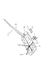
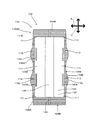
図1に示すように、清掃用具Aは、清掃体ホルダ200と清掃体100で構成されている。清掃体ホルダ200は、清掃体100に着脱可能であり、清掃体100を保持するように構成されている。この清掃用具Aが本発明における「清掃具」の一例である。この清掃体ホルダ200が、本発明における「保持具」の一例である。この、清掃体100が、本発明における「清掃シート」の一例である。
As shown in FIG. 1, the cleaning tool A includes a
清掃体100は、長手方向Yと、長手方向Yと交差する方向によって規定される長手交差方向Xの双方に延在するように構成される。この長手方向Yは、清掃体100に清掃体ホルダ200を挿入する方向と平行な方向により規定される。この清掃体100に清掃体ホルダ200を挿入する方向は、挿入方向Y1とされる。この挿入方向Y1と反対向きの方向は引抜方向Y2とされる。
長手方向Yおよび長手交差方向Xのそれぞれと交差する方向は、厚み方向Zとされる。なお、本発明に係る実施形態の説明において、特別の記載がない限りは、「交差」とは「直交」を意味するものである。
この長手方向Yが、本発明における「長手方向」の一例である。この、長手交差方向Xが、本発明における「長手交差方向」の一例である。この厚み方向Zが、本発明における「厚み方向」の一例である。
The
A direction intersecting with each of the longitudinal direction Y and the longitudinal crossing direction X is a thickness direction Z. In the description of the embodiment according to the present invention, unless otherwise specified, “intersection” means “orthogonal”.
This longitudinal direction Y is an example of the “longitudinal direction” in the present invention. This longitudinal cross direction X is an example of the “longitudinal cross direction” in the present invention. This thickness direction Z is an example of the “thickness direction” in the present invention.
清掃体100において、長手交差方向Xの中心となる点を長手交差方向中心点XCPと規定する。なお、長手交差方向中心点XCPを形成するための長手交差方向Xは、清掃体100上における任意の箇所の長手交差方向Xを適宜採択し得るものである。
そして、長手交差方向中心点XCPを通過する、長手方向Yと平行な直線を長手方向中心線YCLと規定する。
In the
A straight line passing through the longitudinal cross-direction center point XCP and parallel to the longitudinal direction Y is defined as a longitudinal center line YCL.
長手交差方向中心点XCPから清掃体100が存在しない領域へ向く方向を外側方向100D1と規定する。さらに、清掃体100が存在しない領域から長手交差方向中心点XCPへ向く方向を内側方向100D2と規定する。
A direction from the longitudinal cross direction center point XCP to the region where the
(清掃体ホルダの構成)
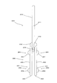
図2に示すように、清掃体ホルダ200は、ハンドル部210および清掃体保持部220を主体として構成されている。ハンドル部210は、長尺状に形成されており、清掃時にユーザに保持される部材である。ハンドル部210は、ハンドル211とハンドル接合部212を有している。ハンドル接合部212は、清掃体保持部220の連接部230に接合されている。そして、ハンドル211は、ハンドル接合部212から延在する長尺状に形成されている。このハンドル部210が、本発明における「把持部」の一例である。この清掃体保持部220が、本発明における「保持部」の一例である。
(Configuration of cleaning body holder)
As shown in FIG. 2, the cleaning
清掃体保持部220は、樹脂材料にて成型されており、清掃体100を保持するための部材である。清掃体保持部220は、長尺状に形成された2つの保持部材221、凸部260および押え板270等を主体として構成されている。具体的には、清掃体保持部220は、ポリプロピレン(PP)が使用されている。なお、清掃体保持部220は可撓性を有する樹脂材料を適宜選択することができる。例えば、ポリエチレン(PE)、ポリエチレンテレフタラート(PET)、アクリロニトリル−ブタジエン−スチレン樹脂(ABS)、ポリエステル系の熱可塑性エラストマーを使用できる。
The cleaning
保持部材221は、連接部230からハンドル211が延在する方向と反対の方向に向かって延在して形成されている。すなわち、保持部材221は、連接部230と、先端部240と、連接部230から先端部240に向かって延在した中間部250とを有する。2つの保持部材221の先端部240はそれぞれ自由端となっている。
The holding
凸部260は、中間部250における外側方向100D1に設けられる。凸部260は、連接部230側に設けられた第1の凸部261と、先端部240側に設けられた第2の凸部262とからなる。
The
押え板270は、連接部230から突出して形成されている。押え板270は、一対の保持部材221の間に、保持部材221と平行に延在するように形成されている。押え板270は、下方に向けて凸形状となるように湾曲して形成される板状部材として構成され、更に下面に係止突部(図示省略)を備えている。
The holding
(清掃体の構成)
次に図3〜図8を参照しつつ、清掃体100について説明する。清掃体100は、清掃対象の塵芥などの汚れを捕集する、汚れ捕集機能を有するシート状の清掃体である。図4、図7に示すように、清掃体100は、平面視で長方形状に形成されている。
この清掃体100は、一回使用を目安とした使い捨てタイプのものや、清掃対象の被清掃面から除去したごみや埃を保持しつつ複数回の使用を目安として交換を行う使い捨てタイプのものであってもよいし、或いは洗濯などを行ったうえで繰り返し使用することが可能なタイプのものであってもよい。
(Configuration of cleaning body)
Next, the
This
清掃体100において、基部120は第1のシート体121により形成されている。基部120は、長手交差方向X上の端部120Aと、長手方向Y上の端部120Bと、一方の面120Cと、他方の面120Dとを有する。この基部120、第1のシート体121、一方の面120C、他方の面120Dが、本発明における「基部」、「第1のシート体」、「一方の側」、「他方の側」のそれぞれ一例である。
In the
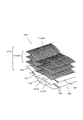
基部120の一方の面120Cには、繊維集合体110GFが配置される。基部120の他方の面120Dには、第2のシート体122が配置される。
これらの積層された基部120、繊維集合体110GF、第2のシート体122は、いずれも清掃体100の長手方向Yに長尺状に延在している。
繊維集合体110GFは、汚れ捕集機能を有する刷毛部110を形成する。この繊維集合体110GFが、本発明に係る「繊維集合体」の一例である。この刷毛部110が本発明における「刷毛部」の一例である。なお、この実施形態に係る清掃体100のように、基部120の一方の面120C側に配置されている繊維集合体110GFを、第1の繊維集合体110GF1とする。
The fiber assembly 110GF is disposed on one
These
The fiber aggregate 110GF forms a
繊維集合体110GFは、繊維110SFの集合体により形成される。この発明において、繊維110SFとは、典型的な繊維による単一の繊維構造体や、典型的な繊維が長さ方向および/または径方向にそろった繊維構造体(撚糸、紡績糸、複数の長繊維が部分的に接続された糸材など)、ないし当該繊維構造体の集合体とされる。ここで「典型的な繊維」とは、糸、織物などの構成単位であり、太さに比して十分な長さを持つ、細くてたわみやすい形態のものである。典型的には長い連続状の繊維が長繊維(フィラメント)とされ、短い繊維が短繊維(ステープル)とされる。
繊維110SFは熱可塑性繊維を一部に含み、それぞれの繊維110SFが融着(「溶着」ともいう)可能とされている。
繊維集合体110GFは、所定の繊維配向方向110Dにて並列に並べられるとともに、厚み方向Zに積層された複数の繊維110SFにより形成される。本発明の実施形態において、繊維配向方向110Dは、長手交差方向Xと概ね合致する。一方、繊維110SFは柔軟な素材であるため、容易に屈曲、変形される。よって、繊維110SFの繊維配向方向110Dとは、製品の設計上における繊維配向性のことを示すものである。
The fiber aggregate 110GF is formed by an aggregate of fibers 110SF. In this invention, the fiber 110SF is a single fiber structure composed of typical fibers, or a fiber structure in which typical fibers are aligned in the length direction and / or radial direction (twisted yarn, spun yarn, a plurality of long lengths). A thread material in which fibers are partially connected), or an aggregate of the fiber structure. Here, the “typical fiber” is a structural unit such as a yarn or a woven fabric, and has a length that is sufficiently long compared to the thickness, and is in a thin and flexible form. Typically, long continuous fibers are long fibers (filaments), and short fibers are short fibers (staples).
The fibers 110SF partially include thermoplastic fibers, and each fiber 110SF can be fused (also referred to as “welding”).
The fiber aggregate 110GF is formed by a plurality of fibers 110SF arranged in parallel in a predetermined
この繊維集合体110GFの繊維110SFは、中央接合部140と溶着される端部である接続端部110SFAを有する。そして、繊維110SFは、接続端部110SFAと反対側の端部である開放端部110SFBを有する。この開放端部110SFBは自由端とされる。
この接続端部110SFAが本発明に係る「接続端部」の一例である。この開放端部110SFBが、本発明に係る「開放端部」の一例である。
The fiber 110SF of the fiber assembly 110GF has a connection end portion 110SFA that is an end portion to be welded to the central
The connection end 110SFA is an example of the “connection end” according to the present invention. The open end portion 110SFB is an example of the “open end portion” according to the present invention.
なお、図3において、繊維集合体110GFは、三つの繊維層が積層して形成されているが、繊維層の数は必要に応じて1または複数とすることができる。この繊維集合体110GFは、所定の平面や曲面による面構造を有するとともに、ある程度の厚みを有する立体形状として、或いは薄肉シート形状として構成されるのが好ましい。繊維集合体110GFは、典型的にはポリエチレン(PE)、ポリプロピレン(PP)、ポリエチレンテレフタレート(PET)、ナイロン、レーヨンなどを材質とし、実用上はトウを開繊することによって得られる長繊維(フィラメント)の集合体が用いられることが好ましい。特には、芯部分がポリプロピレン(PP)或いはポリエチレンテレフタレート(PET)であり、この芯部分の外面を覆う鞘部分がポリエチレン(PE)の複合繊維を用いて繊維集合体110GFが構成されるのが好ましい。また、この繊維集合体110GFを形成する繊維の繊度110SFは、1〜50dtexのものが好ましく、更には2〜10dtexのものが好ましい。また、各繊維集合体は概ね同様の繊度の繊維から構成されてもよいし、或いは各繊維集合体が異なる繊度の繊維を含む構成であってもよい。 In FIG. 3, the fiber assembly 110GF is formed by laminating three fiber layers, but the number of fiber layers may be one or more as necessary. The fiber assembly 110GF preferably has a surface structure of a predetermined plane or curved surface, and is configured as a three-dimensional shape having a certain thickness or a thin sheet shape. The fiber aggregate 110GF is typically made of polyethylene (PE), polypropylene (PP), polyethylene terephthalate (PET), nylon, rayon, etc., and is practically a long fiber (filament) obtained by opening the tow. ) Is preferably used. In particular, the core portion is preferably made of polypropylene (PP) or polyethylene terephthalate (PET), and the sheath portion covering the outer surface of the core portion is preferably composed of a composite fiber of polyethylene (PE) to form the fiber assembly 110GF. . The fineness 110SF of the fibers forming the fiber assembly 110GF is preferably 1 to 50 dtex, more preferably 2 to 10 dtex. In addition, each fiber assembly may be composed of fibers having substantially the same fineness, or each fiber assembly may include fibers having different finenesses.
また、清掃時の汚れ捕集機能を向上させるために、繊維集合体110GFには、油剤が供給される。この油剤は、流動パラフィンを主成分とする。
また、清掃時の掃き出し機能を向上させるためには、剛性の高い繊維110SF、すなわち繊度が高い繊維110SFを含む繊維集合体110GFを用いるのが好ましい。また、繊維集合体110GFは、捲縮繊維を有する構成されるのが好ましい。ここでいう捲縮繊維は、周知の捲縮処理が付与された繊維として構成され、繊維同士が絡み易い構造とされる。このような捲縮繊維を用いると、繊維集合体110GFが清掃体ホルダ200装着前の状態よりも嵩高となり、更に捲縮部分にごみを取り込み易い構造とされる。本構造は、特にトウ繊維から形成された捲縮繊維を用いることによって実現され得る。
Moreover, in order to improve the dirt collection function at the time of cleaning, an oil agent is supplied to the fiber assembly 110GF. This oil agent is mainly composed of liquid paraffin.
In addition, in order to improve the sweeping function at the time of cleaning, it is preferable to use a fiber assembly 110GF including a highly rigid fiber 110SF, that is, a fiber 110SF having a high fineness. Moreover, it is preferable that the fiber assembly 110GF includes crimped fibers. A crimped fiber here is comprised as a fiber to which the well-known crimping process was provided, and is set as the structure where fibers are easy to get entangled. When such a crimped fiber is used, the fiber assembly 110GF is bulkier than the state before the
刷毛部110を構成する繊維集合体110GFの繊維110SFは、長手交差方向Xにおいて同一の長さを有する。ここで、「同一の長さ」であるが、上述した通り繊維110GFとして捲縮繊維を使用した場合は、個々の捲縮繊維同士における捲縮状態が必ずしも一致するものではない。よって、個々の繊維110SFの長さを比較すると、完全に同一の長さではない場合がある。よって、本願発明に係る「同一の長さ」とはあくまでも「設計上の同一の長さ」のことを示すものである。
ここで、「設計上の同一の長さ」につき説明する。清掃体100は、後述する製造工程において、機械方向M連続する積層された資材が、機械方向Mと交差する方向において所定の二つの領域にて切断されることにより形成される。この場合、所定の二つの領域が切断される方向が直線状であり、なおかつ平行である場合は「設計上の同一の長さ」となる。
なお、ここで「直線状」とは必ずしも「完全な直線」を示すものではなく、例えばデザイン上等の都合により湾曲していたとしても、実質的に「直線」であれば足りるものである。
The fibers 110SF of the fiber assembly 110GF constituting the
Here, “same design length” will be described. The
Here, the “straight line” does not necessarily indicate a “perfect straight line”. For example, even if it is curved due to design reasons or the like, it is sufficient if it is substantially “straight line”.
図7に示すように、第2のシート体122は、長手方向Yにおいて、基部120よりも短い長方形状の不織布で形成されたシートである。
基部120(第1のシート体121)および第2のシート体122を構成する不織布は、いずれも典型的には熱溶融性繊維(熱可塑性繊維)からなるシート状の不織布が使用されている。すなわち、これら基部120および第2のシート体122は、「不織布シート」とも称呼される。なお、清掃時の掃き出し機能を向上させるためには、剛性の高い不織布を用いるのが好ましい。
なお、この不織布は、ポリエチレン(PE)、ポリプロピレン(PP)、ポリエチレンテレフタレート(PET)などの合成繊維が使用される。また、不織布の形態としては、エアースルー法や、スパンボンド法により形成されたものが使用される。
一方、不織布以外であっても、布帛や、合成樹脂によるフィルム体などを使用することもできる。
As shown in FIG. 7, the
As for the nonwoven fabric which comprises the base 120 (1st sheet body 121) and the
In addition, synthetic fibers, such as polyethylene (PE), polypropylene (PP), and polyethylene terephthalate (PET), are used for this nonwoven fabric. Moreover, as a form of a nonwoven fabric, what was formed by the air through method or the spun bond method is used.
On the other hand, even if it is other than a nonwoven fabric, a cloth, a film body made of a synthetic resin, or the like can also be used.
基部120と第2のシート体122は、清掃体100の長手方向中心線YCLに沿って延在する中央接合部140と、中央接合部140の両側に位置する複数の第1の接合部141にて溶着接合されている。すなわち、図7に示すように、基部120と、第2のシート体122と、繊維集合体110GFとが、中央接合部140において溶着接合されている。また、基部120と、第2のシート体122と、一部の繊維集合体110GFとが第1の接合部141において溶着接合されている。なお、長手方向Yにおける両端側に位置する第1の接合部141は第2のシート体122が存在しない位置に形成されている。よって、長手方向Yにおける両端側に位置する第1の接合部141は、基部120と、一部の繊維集合体110GFのみを接合する。
この中央接合部140が、本発明に係る「第1の繊維接合部」の一例である。
The
The central joint 140 is an example of the “first fiber joint” according to the present invention.
中央接合部140と、第1の接合部141に挟まれた領域の内、基部120と第2のシート体122の間には、長手方向Yに延在する一対の保持空間130が形成されている。また、保持空間130における長手方向Yの両端には、開口部131それぞれが形成されている。この保持空間130が、本発明における「挿入部」の一例である。
なお、換言すると、保持空間130は、長手交差方向Xにおける一対の第1の接合部141同士の間における基部120の所定領域と、第2のシート体122の所定領域とにより形成される。
A pair of holding
In other words, the holding
第1の接合部141は、長手方向Yに概ね沿って複数連続して形成される。一方、長手方向Yにおいて隣接する第1の溶着接合部141が、必ず長手方向Yに一致して配置される必要はない。第1の溶着接合部141の配置形態は、デザイン性や、清掃体保持部220の形状によって、適宜設計することが可能である。この際、第1の溶着接合部141を連続した線状にて形成することができるのは勿論である。
A plurality of first joining
さらに、基部120の長手交差方向X上の端部120Aと、中央接合部140との間における所定領域には、側方接合部140Aが設けられる。側方接合部140Aは、長手交差方向Xにおいては、基部120の長手交差方向X上の120Aと、第1の溶着接合部141との間に設けられる。また、側方接合部140Aは、長手方向Yにおいては、長手方向Yと平行な方向において、間隔を空けて二か所に設けられている。側方接合部140Aは、長手交差方向Xにおいてそれぞれ一対とされる。
側方接合部140Aは、基部120と、第2のシート122と、繊維集合体110GFとを接合する。
なお、側方接合部140Aは、長手方向Yにおいて二か所である必要はなく、単一であっても、さらに複数であっても良い。また、長手方向Yに平行である必要はない。
この側方接合部140Aが、本発明に係る「第2の繊維接合部」の一例である。
Furthermore, a lateral joint 140A is provided in a predetermined region between the
The side joint 140A joins the
Note that the side joints 140A do not have to be two in the longitudinal direction Y, and may be single or plural. Further, it is not necessary to be parallel to the longitudinal direction Y.
This lateral joint 140A is an example of the “second fiber joint” according to the present invention.
なお、上述した中央接合部140、第1の接合部141、側方接合部140Aは、熱による溶着により形成されている。
一方、本発明に係る接合部は、超音波溶着、縫製、ホットメルト接着剤などによる粘着剤にて形成することも可能である。
The central joint 140, the first joint 141, and the side joint 140A described above are formed by welding with heat.
On the other hand, the joint portion according to the present invention can also be formed by an adhesive such as ultrasonic welding, sewing, or a hot melt adhesive.
刷毛部110は、第1の刷毛領域111と、第2の刷毛領域112とを有する。第2の刷毛領域112は、第1の刷毛領域111よりも長く構成された突出領域112Lを有する。
第1の刷毛領域111は、長手交差方向Xにおいて、側方接合部140Aにより接合されていない繊維110SFにより形成されている。
第2の刷毛領域112は、長手交差方向Xにおいて、側方接合部140Aにより接合されている繊維により形成されている。
The
The
The
第2の刷毛領域112は、第1の刷毛領域111よりも長く形成されている。ここで、「長く」につき図5に基づき説明する。
長手交差方向Xにおいて、長手方向中心線YCLと第1の刷毛領域111における長手交差方向X上の端部111Bとを結ぶ直線の内、最も長い直線を第1の刷毛領域長さ111Dとする。
長手交差方向Xにおいて、長手方向中心線YCLと第2の刷毛領域112における長手交差方向X上の端部112Bとを結ぶ直線の内、最も長い直線を第2の刷毛領域長さ112Dとする。
第2の刷毛領域112が、第1の刷毛領域111よりも長いとは、第2の刷毛領域長さ112Dが、第1の刷毛領域長さ111Dよりも長いことを意味する。
なお、第1の刷毛領域111よりも長い領域である第2の刷毛領域112が、突出領域112Lを構成する。
The
In the longitudinal cross direction X, the longest straight line among the straight lines connecting the longitudinal center line YCL and the
In the longitudinal cross direction X, the longest straight line among the straight lines connecting the longitudinal center line YCL and the
The
In addition, the 2nd brush area |
なお、本発明に係る清掃体100においては、繊維110SFが柔軟である。従って、ユーザにより使用された場合には、繊維110SFの形状が変化する。この結果、第2の刷毛領域長さ112Dが、第1の刷毛領域長さ111Dよりも長いという関係を構築しない場合が生ずる。
突出領域112Lは、ユーザが清掃用具Aを使用する際に、所定の作用および効果を発揮するものである。よって、上述した第1の繊維長さ111Dと第2の繊維長さ112との関係は、清掃体100を製造した直後や、ユーザが製品を購入して清掃体100を取り出した直後や、ユーザが清掃体100を使用するにあたって清掃体100自体を大きく揺り動かし、各繊維110SF間の距離を広げて嵩高状態にした直後などに形成すれば足りるものである。
In the
When the user uses the cleaning tool A, the
本発明の実施形態に係る清掃体100においては、第1の刷毛領域111は、長手方向Y上の端部100Bに設けられている。また、第1の刷毛領域111と第2の刷毛領域112とは、交互に配置されている。
一方、第2の刷毛領域112が、長手方向Y上の端部100Bに設けられている構成でもよく、また、第1の刷毛領域111と第2の刷毛領域112とがそれぞれ一つずつ形成された構成であってよい。
In the
On the other hand, the
刷毛部110は、清掃対象に当接する当接領域160を有する。図6に基づき、当接領域160を説明する。
当接領域160は、第1の当接領域161と、第2の当接領域162と、第3の当接領域163を有する。第1の当接領域161は、第1の刷毛領域111に形成される。第2の当接領域162は、第2の刷毛領域112における中央接合部140と側方接合部140Aとの間に形成される。第3の刷毛領域163は、第2の刷毛領域112における側方接合部140Aと開放端部110SFBとの間に形成される。
この当接領域160が本発明に係る「当接領域」の一例である。この第1の当接領域161が本発明に係る「第1の当接領域」の一例である。この第2の当接領域162が本発明に係る「第2の当接領域」の一例である。この第3の当接領域が本発明に係る「第3の当接領域」の一例である。
The
The
The
第2の当接領域162は、厚み方向Zにおいて第1の当接領域161よりも低く形成された低位領域162Aを有する。低位領域162Aは、隣接する第1の当接領域161へ清掃対象の塵芥を誘導可能な誘導領域162Bとされている。
なお、低位領域162Aと誘導領域162Bは、第2の当接領域162と第3の当接領域163との境界である側方接合部140Aを含む領域として形成される。よって、低位領域162Aと誘導領域162Bは、第3の当接領域163に形成されるとも言える。また、低位領域162Aと誘導領域162Bは、第2の当接領域162と第3の当接領域163との間に形成されるとも言える。
以下、便宜上、低位領域162Aと誘導領域162Bは、第2の当接領域162に設けられていることを中心に説明する。
The
The
Hereinafter, for the sake of convenience, the
低位領域162Aが、厚み方向Zにおいて、第2の当接領域162における第1の当接領域161よりも「低く」形成されていることにつき、説明する。
側方接合部140Aは、当接領域160と対向する側の領域である当接対向領域140A1と、当接領域160側の領域である当接側領域140A2とを有する。この当接対向領域140A1と、当接領域140A2との間における厚み方向Zの長さにおいて、最も短い長さを第2の当接領域高さ162Zとする。
次に、この第2の当接領域高さ162Zを求めた地点における、側方接合部140の当接対向領域140A1上の点を高さ測定用点140A1Pとする。高さ測定用点140A1Pを通過する、長手方向Yと平行な直線を、高さ測定用直線161Yとする。この高さ測定用直線と、第1の当接領域161との間における厚み方向Zの長さにおいて、最も長い長さを第1の当接領域高さ161Zとする。
すなわち、厚み方向Zにおいて、第2の当接領域162が、第1の当接領域161よりも「低い」とは、第2の当接領域高さ162Zが、第1の当接領域高さ161Zよりも「短い」ことを意味するものである。
The fact that the
140 A of side junction parts have contact | abutting opposing area | region 140A1 which is an area | region facing the contact area |
Next, a point on the contact facing area 140A1 of the side joint 140 at the point where the second
That is, in the thickness direction Z, the
なお、本発明に係る清掃体100においては、繊維110SFが柔軟である。従って、ユーザにより使用された場合には、繊維110SFの形状が変化する。この結果、第2の当接領域高さ162Zが、第1の当接領域高さ161Zよりも「短い」という関係を構築しない場合が生ずる。
低位領域162Aは、ユーザが清掃用具Aを使用する際に、所定の作用および効果を発揮するものである。よって、上述した第1の当接領域高さ161Zと第2の当接領域高さ162Zとの関係は、清掃体100を製造した直後や、ユーザが製品を購入して清掃体100を取り出した直後や、ユーザが清掃体100を使用するにあたって清掃体100自体を大きく揺り動かし、各繊維110SF間の距離を広げて嵩高状態にした直後などに形成すれば足りるものである。
In the
The
よって、低位領域A162は、側方接合部140Aの当接側領域140A2を含む領域となる。さらに、誘導領域162Bは、低位領域162Aにおける長手方向Yと平行な領域となる。誘導領域162Bを延出した場合には、第1の当接領域161の側部に当接することとなる。よって、誘導領域162Bを経由した清掃対象の塵芥は、第1の当接領域161の側部領域161Aに捕捉されやすくなる。
Accordingly, the lower region A162 is a region including the contact side region 140A2 of the side joint 140A. Furthermore, the
第2の当接領域162を形成する繊維110SFは、その両端が中央接合部140と、側方接合部140Aとにより固定されている。よって、第2の当接領域162を構成する繊維110SFは、第1の当接領域161を形成する繊維110SFや、第3の当接領域163を形成する繊維110SFと比べて、可動幅が狭いものである。よって、ユーザが清掃用具Aを使用した場合、例えば清掃対象に強く付着している塵芥に対し、抵抗を加えることができる。よって、第2の当接領域162は、清掃対象の塵芥に対して抵抗を加えることができる抵抗領域162Cとされる。この抵抗領域162Cが、本発明に係る「抵抗領域」の一例である。
Both ends of the fiber 110SF forming the
清掃体110は、短冊片150を有する。短冊片150は、基部120における長手交差方向X上の端部に設けられた複数の切込み線の間に形成された第1の短冊片151と、第2のシート体122における長手交差方法X上の端部に設けられた複数の切込み線の間に形成された第2の短冊片152とからなる。なお、基部120および第2のシート体122における切込み線は、ジグザグ状とされる。短冊片150をジクザグ状とすることによって、ごみを引っ掛けて捕捉し易い清掃機能の高い構造が実現される。なお、短冊片の形状に関しては、ジクザグ状、直線状、曲線状などのうちの単一種類或いは複数種類の形状を適宜用いることができる。
なお、短冊片150としては、第1の短冊片151もしくは第2の短冊片152のいずれか一方でも良い。
The
The
(清掃体ホルダと清掃体の係合)
次に図9、図10を参照しつつ、清掃体ホルダ200と清掃体100の係合について説明する。図9に示すように、保持部材221はそれぞれ、保持空間130に挿入が可能とされている。保持部材221が挿入方向Y1に沿って保持空間130に挿入されることで、清掃体100が清掃体ホルダ200に保持される。一方、係合している清掃体ホルダ200と清掃体100とを分離するためには、清掃体ホルダ200を、引抜方向Y2に沿って保持空間130から引き抜く。
(Engagement of cleaning body holder and cleaning body)
Next, the engagement between the cleaning
清掃体ホルダ200と清掃体100の係合状態においては、凸部260は、隣接する第1の接合部141同士の間に配置される。これにより、清掃体ホルダ200と清掃体100の係合状態が確実に維持される。
また、押え板270は、保持部材221とともに第2のシート体122を挟持する。
In the engaged state of the
In addition, the holding
(作用)
次に、本発明の実施形態に係る清掃用具Aの作用を説明する。清掃体100の長手交差方向X上の端部100Aを使用して清掃する場合には、第2の刷毛領域112の突出領域112Lを清掃対象に当接させる。そして、清掃体100を長手方向Yに概ね沿った方向に移動させることができる。これにより、清掃対象の塵芥を掻き出すことが可能となる。
なお、突出領域Lを複数形成した場合には、清掃対象に対して複数の突出領域112Lを連続して当接させることができる。よって、より一層の清掃効果の向上を図ることができる。
(Function)
Next, the operation of the cleaning tool A according to the embodiment of the present invention will be described. When cleaning is performed using the
When a plurality of protruding regions L are formed, the plurality of protruding
次に、図11に基づき、当接領域160を広く押し当てて清掃作業を行う場合を説明する。例えば、床Fなどを清掃するにあたり、ユーザはハンドル211を持ち、清掃体100の清掃領域160を床Fに押し当てる。そしてユーザは、床Fの上にて清掃体100を動かす。この際、例えば第1の当接領域161の表面では捕捉しきれなかった塵芥が発生したものとする。この場合、この第1の当接領域161で捕捉されなかった塵芥は、ユーザの清掃作業によって、低位領域162Aの誘導領域162Bへと移行される。そして、誘導領域162Bへ移行された塵芥は、第2の当接領域162もしくは第3の当接領域163にて捕捉される。ここで、さらに第2の当接領域162もしくは第3の当接領域で捕捉されなかった塵芥は、第1の当接領域161の側部領域161Aにて捕捉される。
なお、繊維110SGが柔軟であることから、強い圧力にて清掃体100を床Fに押し付けた場合は、低位領域162Aと誘導領域162Bがつぶれてしまう恐れがある。一方、低位領域162Aと誘導領域162とが形成される範囲内にて清掃用具Aを使用した場合、塵芥の捕捉が行えるのであれば、本願発明を構成するものである。
Next, based on FIG. 11, a case where the cleaning operation is performed by pressing the
In addition, since the fiber 110SG is flexible, when the
また、例えば床Fに付着し、通常の清掃作業における「払う」動作にて捕捉できない塵芥が想定される。このような場合、ユーザは、抵抗領域162Cをこの付着した塵芥に対し押し当て、清掃作業を行う。その結果、抵抗領域162における可動領域の少ない繊維110SFにより、塵芥が床Fから剥離される。
Further, for example, dust that adheres to the floor F and cannot be captured by the “pay” operation in a normal cleaning operation is assumed. In such a case, the user presses the
すなわち、本発明に係る清掃用具Aにおいては、突出領域Lにより、塵芥の掻き出し作業を向上させることができる。また、低位領域162Aおよび誘導領域162Bにより、塵芥が繊維集合体110GFに捕捉される機会を増加させることができる。また、抵抗領域162Cにより、清掃対象に付着した塵芥を清掃対象から剥離させることができる。
That is, in the cleaning tool A according to the present invention, the protruding area L can improve the dust scraping operation. Further, the
(製造工程)
次に、図12〜図20において、本発明に係る実施形態の清掃用具Aの製造方法を説明する。まず、具体的な製造工程の説明をする前に、本発明に係る繊維集合体110GFを形成する繊維110SFの説明を行う。
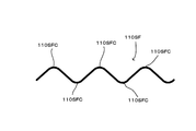
図12は、繊維集合体110を形成する繊維110SFである。なお、図12に係る繊維110SFは、外力がかかっていない静止状態を示す。繊維110SFは、捲縮繊維であるため、複数の屈曲部110SFCを有し、ジグザグ状とされている。この屈曲部110SFCはクリンプ部とも呼ばれる。
繊維110SFは、屈曲部110SFCを有することにより、伸縮が可能となっている。図13は、静止状態の繊維110SFの両端部に対し、それぞれ対向する方向へ外力(張力)を加えた状態を示す。このように、繊維110SFは、屈曲部110SF間の距離が離間することにより延びることが可能となる。一方、この外力を解除した状態においては、繊維110SFは、図13に示す延ばされた状態から、図12に示す静止状態へと復帰する。
(Manufacturing process)
Next, in FIGS. 12-20, the manufacturing method of the cleaning tool A of embodiment which concerns on this invention is demonstrated. First, before describing the specific manufacturing process, the fiber 110SF forming the fiber assembly 110GF according to the present invention will be described.
FIG. 12 shows a fiber 110SF that forms the
The fiber 110SF can be expanded and contracted by having the bent portion 110SFC. FIG. 13 shows a state in which an external force (tension) is applied in opposite directions to both ends of the stationary fiber 110SF. Thus, the fibers 110SF can be extended by separating the distance between the bent portions 110SF. On the other hand, in the state where the external force is released, the fiber 110SF returns from the extended state shown in FIG. 13 to the stationary state shown in FIG.
ここで、基部120と繊維集合体110GFは、伸縮弾性率が異なる。すなわち、繊維集合体110GFの伸縮弾性率は、基部120の伸縮弾性率よりも高いものである。具体的には、繊維集合体110GFの伸縮弾性率は75.7%であり、基部120の伸縮弾性率は56.0%である。
なお、伸縮弾性率の測定においては、次の試験により行った。
(1)繊維集合体110GFの試験片と、基部120の試験片を準備する。試験片は、500mmの長さとする。
なお、繊維集合体110GFは、ポリエチレン(PE)が鞘材、ポリエチレンテレフタレート(PET)が芯材の芯鞘複合繊維により形成されたトウ繊維を用いた。このトウ繊維は、繊維1本に係る繊度が3.5dtexである。繊維集合体全体としての繊度は110,000dtexである。
また、基部120は、ポリエチレン(PE)が鞘材、ポリエチレンテレフタレート(PET)が芯材の芯鞘複合繊維により形成されたスパンボンド不織布を用いた。この不織布は、坪量が20g/m2である。また、幅を190mmとした。
(2)試験片中の長手方向に、所定の長さの始端と終端を示す印を付す。なお、この印は200mmの長さを示すものとする。この状態における始端と終端間の長さをL0とする。L0は、すなわち200mmとなる。
(2)試験片の上端をクリップにて固定する。
(3)試験片の下端における全幅に荷重がかかるよう、5kgの錘を吊るす。
(4)30秒経過後に、試験片中に付した始端と終端の間の長さを測定する。この長さをL1とする。
(5)錘を除き30秒経過後に、試験片に付した始端と終端の間の長さを測定する。この長さをL2とする。
(6)L1とL2の差を、L1とL0との差で除し、さらに100を乗した数値を、伸縮弾性率とした。
(7)この試験を5回行い、平均の数値を求めた。
Here, the
In addition, in the measurement of elastic modulus of elasticity, it carried out by the following test.
(1) A test piece of the fiber assembly 110GF and a test piece of the base 120 are prepared. The test piece has a length of 500 mm.
The fiber assembly 110GF used was a tow fiber formed of a core-sheath composite fiber in which polyethylene (PE) is a sheath material and polyethylene terephthalate (PET) is a core material. This tow fiber has a fineness of 3.5 dtex for one fiber. The fineness of the entire fiber assembly is 110,000 dtex.
The
(2) A mark indicating the start and end of a predetermined length is attached in the longitudinal direction of the test piece. This mark indicates a length of 200 mm. The length between the start end and the end end in this state is L0. L0 is 200 mm.
(2) Fix the upper end of the test piece with a clip.
(3) A 5 kg weight is suspended so that a load is applied to the entire width at the lower end of the test piece.
(4) After 30 seconds have elapsed, the length between the start end and the end attached to the test piece is measured. This length is L1.
(5) After the elapse of 30 seconds except for the weight, the length between the start end and the end attached to the test piece is measured. This length is L2.
(6) A value obtained by dividing the difference between L1 and L2 by the difference between L1 and L0 and further multiplying by 100 was taken as the elastic modulus of elasticity.
(7) This test was performed 5 times to obtain an average numerical value.
図14は、製造工程を示すフローチャートである。製造工程は、基部120と、第2のシートと、一部の繊維集合体110GFとなる資材を積層する工程である第1の工程S11と、第1の工程S11により積層した資材を接合する工程である第2の工程S12と、第2の工程S12で接合した資材に一部の繊維集合体110GFを積層する工程である第3の工程S13と、第3の工程S13で積層した資材を接合する工程である第4の工程S14と、S14で接合した資材を所定の形状に切断する工程である第5の工程S15と、第1の刷毛領域111と第2の刷毛領域112を形成する工程である第6の工程S16とからなる。
なお、本発明の実施形態に係る清掃体100は、短冊片150を有するものである。一方、説明の便宜上、短冊片150の製造工程においては省略する。
FIG. 14 is a flowchart showing the manufacturing process. The manufacturing process includes a first step S11 that is a step of laminating the
In addition, the
図15は、第1の工程S11を示す。第1の工程S11では、基部120となる第1のシート体121を形成するための第1のシート資材1211と、第2のシート体122を形成するための第2のシート資材1221と、第1の繊維集合体110GF1の一部を形成するための第1の繊維集合資材110GF1Aとが供給される。この結果、第1のシート資材1211の一方の側には第1の繊維集合資材110GF1Aが配置される。また、第1のシート資材121の他方の側には、第2のシート資材1221が配置される。
なお、本発明の製造工程においては、各資材は支持ロールRにより支持されるとともに、図示しない駆動機構により、機械方向Mに移送される。
なお、第1の繊維集合資材110GF1Aの繊維配向方向110Dは、機械方向Mとおおよそ一致する。
FIG. 15 shows the first step S11. In the first step S11, a
In the manufacturing process of the present invention, each material is supported by the support roll R and is transferred in the machine direction M by a drive mechanism (not shown).
In addition, the
図16は、第2の工程S12を示す。第2の工程S12では、第2のシート資材1221と、第1のシート資材1211と、第1の繊維集合資材110GF1との全層が溶着される。この際、第2のシート資材1221と、第1のシート資材1211と、第1の繊維集合資材110GF1における所定領域の2か所が溶着される。この溶着された箇所は、一対の第1の接合部141を形成する。
FIG. 16 shows the second step S12. In the second step S12, all layers of the
図17は、第3の工程S13を示す。第3の工程S13では、第2の繊維集合資材110GF1Bが供給される。第2の繊維集合資材110GF1Bは、第1の繊維集合資材110GF1Aにおける、第1のシート資材1211が配置されていない側に供給される。
なお、第2の繊維集合資材110GF1Bの繊維配向方向110Dは、機械方向Mとおおよそ一致する。
FIG. 17 shows the third step S13. In the third step S13, the second fiber assembly material 110GF1B is supplied. The second fiber assembly material 110GF1B is supplied to the side of the first fiber assembly material 110GF1A where the
Note that the
図18は、第4の工程S14を示す。第4の工程S14では、第2のシート資材1221と、第1のシート資材1211と、第1の繊維集合資材110GF1Aと、第2の繊維集合資材110GF1Bの全層が、熱溶着により接合される。この接合作業により、中央接合部140と、側方接合部140Aが形成される。
中央接合部140の形成にあっては、第1の繊維集合体110GF1における繊維配向方向110Dを横切る所定の領域の全部が接合される。
側方接合部140Aの形成にあっては、第1の繊維集合体110GF1における繊維配向方向110Dを横切る所定の領域の一部が接合される。具体的には、側方接合部140Aは、繊維配向方向110Dを横切る方向において、二か所が溶着される、
FIG. 18 shows a fourth step S14. In the fourth step S14, all layers of the
In forming the central joint 140, all of the predetermined regions that cross the
In the formation of the side joint 140A, a part of a predetermined region crossing the
なお、中央接合部140と側方接合部140Aとは、単一の接合装置により設けることできる。この場合、中央接合部140と側方接合部140Aは、ほぼ同時に形成される。
一方、中央接合部140を形成する接合装置と、側方接合部140Aを接合する接合装置とを、それぞれ独立した接合装置とすることもできる。この場合、中央接合部140を設けた後に、側方接合部140Aを設けることができる。一方、側方接合部140Aを設けた後に、中央接合部140を設けることもできる。
The central joint 140 and the side joint 140A can be provided by a single joining device. In this case, the center joint 140 and the side joint 140A are formed almost simultaneously.
On the other hand, the joining device that forms the central joint 140 and the joining device that joins the side joint 140A may be independent joint devices. In this case, the side joint 140A can be provided after the central joint 140 is provided. On the other hand, the central joint 140 can be provided after the side joint 140A is provided.
なお、第1の工程S11〜第4の工程S14に亘っては、第1の繊維集合資材110GF1Aに所定の張力が付与されている。具体的な張力は、40Nである。
なお、この第1の繊維集合資材110GF1Aおよび第2の繊維集合資材110GF1Bにかけられた所定の張力は、製造を容易に行うべく、形状を安定させるために掛けられる。
さらに、この張力は、後述する製造工程において、繊維集合資材110GFの繊維110SFを収縮させ、第1の刷毛領域111と第2の刷毛領域112とを形成するために掛けられる。
なお、第1のシート資材1211、第2のシート資材1221においても、形状を安定させるために張力が掛けられる。
Note that a predetermined tension is applied to the first fiber assembly material 110GF1A over the first step S11 to the fourth step S14. A specific tension is 40N.
It should be noted that the predetermined tension applied to the first fiber assembly material 110GF1A and the second fiber assembly material 110GF1B is applied to stabilize the shape for easy manufacture.
Further, this tension is applied to shrink the fibers 110SF of the fiber assembly material 110GF and form the
Note that tension is also applied to the
図19は、第5の工程S15を示す。第5の工程S15では、第2のシート資材1221、第1のシート資材1211、第1の繊維集合資材110GF1A、第2の繊維集合資材110GF1Bを、所定の領域にて切断する。この切断作業により、第2のシート資材1221、第1のシート資材1211、第1の繊維集合資材110GF1A、第2の繊維集合資材110GF1Bは、張力から解放される。
FIG. 19 shows a fifth step S15. In the fifth step S15, the
図20は、第6の工程S16を示す。第6の工程S16では、張力から解放された第1の繊維集合資材110GF1Aに相当する繊維110SFが、長手交差方向Xにおける内側方向100D2へ向かい収縮する。
中央接合部140と、側方接合部140Aの双方に接続する繊維は、第1のシート体121と第2のシート体122とも接続されている。従って、第1のシート体121と第2のシート体122とにより、繊維110SFの収縮が制限される。
一方、中央接合部140のみに接合されている繊維110SFは、第1のシート体121と第2のシート体122と接続された繊維110SFと比較して、大きく収縮する。
この結果、中央接合部140のみに接合された繊維110SFは、第1の刷毛領域111を形成する。中央接合部140と側方接合部140Aとに接合された繊維110SFは、第2の刷毛領域112を形成する。
このようにして、本発明に係る清掃用具Aの清掃体100が製造される。
FIG. 20 shows a sixth step S16. In the sixth step S16, the fiber 110SF corresponding to the first fiber assembly material 110GF1A released from the tension contracts toward the inner direction 100D2 in the longitudinal cross direction X.
The fibers connected to both the central joint 140 and the side joint 140A are also connected to the
On the other hand, the fiber 110SF joined only to the central joint 140 contracts significantly compared to the fiber 110SF connected to the
As a result, the fiber 110SF joined only to the central joint 140 forms the
Thus, the
なお、本発明は上記の実施の形態や製造方法のみに限定されるものではなく、種々の応用や変形が考えられる。例えば、上述した実施形態における清掃用具Aにおいては、保持具200の保持部材211が二つ形成されており、それに対応して清掃体100の保持空間130も二つ形成されている。一方、二つの保持部材211に対し、単一の保持空間130を設けることもできる。さらに、単一の保持部材211に対し、単一の保持空間130を設けることもできる。
In addition, this invention is not limited only to said embodiment and manufacturing method, Various application and deformation | transformation can be considered. For example, in the cleaning tool A in the above-described embodiment, two holding
以下、上記実施形態の変形例につき説明を行うが、上記実施形態における清掃用具Aと同一の構成にあっては、同一の符号を付すとともにその説明を省略する。 Hereinafter, although it demonstrates about the modification of the said embodiment, in the same structure as the cleaning tool A in the said embodiment, while attaching | subjecting the same code | symbol, the description is abbreviate | omitted.
(第1の変形例)
図21に基づき第1の変形例を説明する。なお、第1の変形例に係る清掃体101は、上述の実施形態における清掃体100に比して、保持空間130の構成が異なるものである。
すなわち、第1の変形例に係る清掃体101の保持空間130は、基部120を構成する第1のシート体121のみにて形成される。すなわち、第1のシート体121における所定の面同士を当接させ、接合シート領域121Aを形成する。この接合シート領域121Aにおける所定領域を溶着し、第2の接合部142を形成する。
これにより、長手方向Yに延びる空間である、保持空間130を形成することができる。
なお、この第1の変形例の場合、中央接合部140は、刷毛部110のみを接合することができる。この場合、刷毛部110と基部120とは、接着剤(図示せず)などにより接合することができる。
この第1の変形例に係る清掃体101であっても、第1の刷毛領域111と、第2の刷毛領域112が形成されるため、上述の実施形態における清掃体100と同様の作用および効果を奏する。
(First modification)
A first modification will be described based on FIG. In addition, the
That is, the holding
Thereby, the holding
In the case of the first modification, the central joint 140 can join only the
Even in the
(第2の変形例)
図22に基づき第2の変形例を説明する。なお、第2の変形例に係る清掃体102は、上述の実施形態における清掃体100に比して、保持空間130の構成が異なるものである。
すなわち、第2の変形例に係る清掃体102の保持空間130は、基部120とは独立して形成される。第3のシート体123と、第4のシート体124を重ねる。そして、第3のシート123と第4のシート124における長手交差方向X上の両端部近傍の領域を、長手方向Y方向に沿って溶着し、第4の接合部144を形成する。
これにより、第3のシート123と第4のシート124との間に、長手方向Yに延びる空間である、保持空間130を形成することができる。
なお、この第2の変形例の場合、中央接合部140は、刷毛部110と基部120のみを接合する。第3のシート123は、接着剤などにより基部120と接合され、第5の接合部145を形成する。
この第2の変形例に係る清掃体101であっても、第1の刷毛領域111と、第2の刷毛領域112が形成されるため、上述の実施形態における清掃体100と同様の作用および効果を奏する。
(Second modification)
A second modification will be described based on FIG. In addition, the
That is, the holding
Accordingly, a holding
In the case of the second modification, the central joint 140 joins only the
Even in the
(第3の変形例)
図23に基づき第3の変形例を説明する。なお、第3の変形例に係る清掃体103は、上述の実施形態における清掃体100に比して、保持空間130の構成が異なるものである。
すなわち、第3の変形例に係る清掃体103の保持空間130は、基部120とは独立して形成される。すなわち、第5のシート体125における所定の面同士を当接させ、接合シート領域125Aを形成する。この接合シート領域125Aにおける所定領域を溶着し、第6の接合部146を形成する。これにより、長手方向Yに延びる空間である、保持空間130を形成することができる。
なお、この第3の変形例の場合、中央接合部140は、刷毛部110と基部120のみを接合する。第5のシート125は、接着剤などにより基部120と接合され、第7の接合部147を形成する。
この第3の変形例に係る清掃体103であっても、第1の刷毛領域111と、第2の刷毛領域112が形成されるため、上述の実施形態における清掃体100と同様の作用および効果を奏する。
(Third Modification)
A third modification will be described based on FIG. In addition, the
That is, the holding
In the case of the third modification, the central joint 140 joins only the
Even in the
(第4の変形例)
図24に基づき第4の変形例を説明する。なお、第4の変形例に係る清掃体104は、上述の実施形態における清掃体100に比して、基部120の一方の面120C側だけではなく、他方の面120D側にも刷毛部110が形成されているものである。
すなわち、第2の繊維集合体110GF2を、繊維配向方向110Dを横切る方向の所定の領域により溶着する。この溶着により第8の接合部148が形成される。そして、第2の繊維集合体110GF2を、接着剤などにより実施形態における清掃体100の第2のシート体122に接合する。この接合により第9の溶着部が形成される。このようにして、清掃体104が形成される。
この第4の変形例に係る清掃体104であっても、第1の刷毛領域111と、第2の刷毛領域112が形成されるため、上述の実施形態における清掃体100と同様の作用および効果を奏する。
さらに、基部120の他方の面120D側にも刷毛部110が形成されているため、ユーザの利便性が向上する。
なお、第2の繊維集合体110GF2を、第1の刷毛領域111と、第2の刷毛領域112とを有する構成とし、突出領域Lと、低位領域162Aと、誘導領域162Bと、抵抗領域162Cとを形成することができるのは勿論である。
(Fourth modification)
A fourth modification will be described based on FIG. In addition, the
That is, the second fiber aggregate 110GF2 is welded by a predetermined region in a direction crossing the
Even in the
Furthermore, since the
The second fiber assembly 110GF2 includes a
(第5の変形例)
図25に基づき第5の変形例を説明する。なお、第5の変形例に係る清掃体105は、上述の第1の変形例における清掃体101に比して、基部120の一方の面120C側だけではなく、他方の面120D側にも刷毛部110が形成されているものである。
すなわち、保持空間130を形成する第1のシート体121に、第2の繊維集合体110GF2が接合されるものである。第2の繊維集合体110GF2は、中央領域において溶着される。この中央領域における溶着箇所は、第10の接合部1410を形成する。この第10の接合部141を有する第2の繊維集合体110GF2は、図示しない接着剤などにより、保持空間130を形成する第1のシート体121に接合する。このようにして、清掃体105が形成される。
この第5の変形例に係る清掃体105であっても、第1の刷毛領域111と、第2の刷毛領域112が形成されるため、上述の実施形態における清掃体100と同様の作用および効果を奏する。
さらに、基部120の他方の面120D側にも刷毛部110が形成されているため、上述の第1の変形例に係る清掃体101よりも、ユーザの利便性が向上する。
なお、第2の繊維集合体110GF2を、第1の刷毛領域111と、第2の刷毛領域112とを有する構成とし、突出領域Lと、低位領域162Aと、誘導領域162Bと、抵抗領域162Cとを形成することができるのは勿論である。
(Fifth modification)
A fifth modification will be described based on FIG. In addition, the
That is, the second fiber assembly 110GF2 is joined to the
Even in the
Furthermore, since the
The second fiber assembly 110GF2 includes a
(第6の変形例)
図26に基づき第6の変形例を説明する。なお、第6の変形例に係る清掃体106は、上述の第2の変形例における清掃体102に比して、基部120の一方の面120C側だけではなく、他方の面120D側にも刷毛部110が形成されているものである。
すなわち、第2の繊維集合体110GF2と、第6のシート体126とを中央領域において溶着し、第11の接合部1411を形成する。そして、第6のシート体126における第2の繊維集合体110GF2が配置されていない面と、第4のシート体124とを接着剤などにより接合し、第12の接合部1412を形成する。このようにして、清掃体106が形成される。
この第6の変形例に係る清掃体106であっても、第1の刷毛領域111と、第2の刷毛領域112が形成されるため、上述の実施形態における清掃体100と同様の作用および効果を奏する。
さらに、基部120の他方の面120D側にも刷毛部110が形成されているため、上述の第2の変形例に係る清掃体102よりも、ユーザの利便性が向上する。
なお、第2の繊維集合体110GF2を、第1の刷毛領域111と、第2の刷毛領域112とを有する構成とし、突出領域Lと、低位領域162Aと、誘導領域162Bと、抵抗領域162Cとを形成することができるのは勿論である。
(Sixth Modification)
A sixth modification will be described based on FIG. In addition, the
That is, the second fiber assembly 110GF2 and the
Even in the
Furthermore, since the
The second fiber assembly 110GF2 includes a
(第7の変形例)
図27に基づき第7の変形例を説明する。なお、第7の変形例に係る清掃体107は、上述の第3の変形例における清掃体103に比して、基部120の一方の面120C側だけではなく、他方の面120D側にも刷毛部110が形成されているものである。
すなわち、第2の繊維集合体110GF2と、第7のシート体127とを中央領域において溶着し、第13の接合部1413を形成する。そして、第7のシート体127における繊維集合体110が配置されていない面と、第5のシート体125とを接着剤などにより接合し、第14の接合部1414を形成する。このようにして、清掃体107が形成される。
この第7の変形例に係る清掃体107であっても、第1の刷毛領域111と、第2の刷毛領域112が形成されるため、上述の実施形態における清掃体100と同様の作用および効果を奏する。
さらに、基部120の他方の面120D側にも刷毛部110が形成されているため、上述の第3の変形例に係る清掃体103よりも、ユーザの利便性が向上する。
なお、第2の繊維集合体110GF2を、第1の刷毛領域111と、第2の刷毛領域112とを有する構成とし、突出領域Lと、低位領域162Aと、誘導領域162Bと、抵抗領域162Cとを形成することができるのは勿論である。
(Seventh Modification)
A seventh modification will be described with reference to FIG. Note that the
That is, the second fiber assembly 110GF2 and the
Even in the
Furthermore, since the
The second fiber assembly 110GF2 includes a
(第8の変形例)
図28に基づき第8の変形例を説明する。なお、第8の変形例に係る清掃体108は、上述の実施形態における清掃体100に比して、第2の刷毛領域112が、清掃体108における長手方向Y上の端部108Bに設けられているものである。
この第8の変形例に係る清掃体108であっても、第1の刷毛領域111と、第2の刷毛領域112が形成されるため、上述の実施形態における清掃体100と同様の作用および効果を奏する。
(Eighth modification)
An eighth modification will be described with reference to FIG. In the
Even in the
(第9の変形例)
図29に基づき、第9の変形例を説明する。なお、第9の変形例に係る清掃体109は、上述の実施形態における清掃体100に比して、刷毛部110と基部120の長さが異なるものである。つまり、長手方向Yにおいて、刷毛部110の方が基部120よりも長く形成されている。さらに、長手交差方向Xにおいて、刷毛部110の方が基部120よりも長い。このような構成は、例えば図21にて示した第1の変形例に係る清掃体101のような構造の清掃体により達成できる。すなわち、刷毛部110と保持空間130とをそれぞれ独立して形成する。その際、保持空間130を形成する基部120の大きさを任意の大きさとする。しかる後に、刷毛部110と基部120とを接合する。このようにして、第9の変形例に係る清掃体109が形成される。
この第9の変形例に係る清掃体109であっても、第1の刷毛領域111と、第2の刷毛領域112が形成されるため、上述の実施形態における清掃体100と同様の作用および効果を奏する。
さらに、第1の刷毛領域111が、清掃体109における長手交差方向X上の端部109Aに形成される。また、第2の刷毛領域112が、清掃体109における長手交差方向X上の端部109Aに形成される。よって、清掃体109の長手交差方向X上の端部109Aを清掃対象に当接させる場合は、塵芥の捕捉効果を向上させることができる。
(Ninth Modification)
A ninth modification will be described based on FIG. In the
Even in the
Further, the
なお、本発明の実施形態および変形例は、上述したものに限るものではない。上述した実施形態や各変形例に係る構成を適宜組み合わせることが可能である。また、さらなる形態を追加・変更することが可能である。 In addition, embodiment and the modification of this invention are not restricted to what was mentioned above. It is possible to combine the structure which concerns on embodiment mentioned above and each modification suitably. Further, it is possible to add / change further forms.
(実施の形態ないし実施例本発明の各構成要素の対応について)
清掃具Aは、本発明に係る「清掃具」の一例である。清掃体100、101、102は、本発明に係る「清掃シート」の一例である。清掃体ホルダ200は、本発明に係る「保持具」の一例である。長手方向Yは、本発明に係る「長手方向」の一例である。長手交差方向Xは、本発明に係る「長手交差方向」の一例である。厚み方向Zは、本発明に係る「厚み方向」の一例である。清掃体保持部220は、本発明に係る「保持部」の一例である。ハンドル部210は、本発明に係る「把持部」の一例である。端部100Bは、本発明に係る「長手方向上の端部」の一例である。端部100Aは、本発明に係る「長手交差方向上の端部」の一例である。刷毛部110は、本発明に係る「刷毛部」の一例である。基部120は、本発明に係る「基部」の一例である。保持空間130は、本発明に係る「挿入部」の一例である。繊維配向方向110Dは、本発明に係る「繊維配向方向」の一例である。繊維集合体110GFは、本発明に係る「繊維集合体」の一例である。当接領域160は、本発明に係る「当接領域」の一例である。第1の当接領域161は、本発明に係る「第1の当接領域」の一例である。第2の当接領域162は、本発明に係る「第2の当接領域」の一例である。抵抗領域162Cは、本発明に係る「抵抗領域」の一例である。中央接合部140は、本発明に係る「第1の繊維接合部」の一例である。側方接合部140Aは、本発明に係る「第2の繊維接合部」の一例である。接続端部110SFAは、本発明に係る「接続端部」の一例である。開放端部110SFBは、本発明に係る「開放端部」の一例である。第3の当接領域163は、本発明に係る「第3の当接領域」の一例である。第1のシート121は、本発明に係る「第1のシート体」の一例である。第2のシート体122は、本発明に係る「第2のシート体」の一例である。第3のシート体123は、本発明に係る「第3のシート体」の一例である。第4のシート体124は、本発明に係る「第4のシート体」の一例である。第5のシート体125は、本発明に係る「第5のシート体」の一例である。第6のシート体126は、本発明に係る「第6のシート体」の一例である。一方の面120Aは、本発明に係る「一方の側」の一例である。他方の面120Dは、本発明に係る「他方の側」の一例である。
(Correspondence of each component of embodiment or example of the present invention)
The cleaning tool A is an example of the “cleaning tool” according to the present invention. The cleaning
なお、本発明の実施形態および変形例は、上述したものに限るものではない。上述した実施形態や各変形例に係る構成を適宜組み合わせることが可能である。また、さらなる形態を追加・変更することが可能である。 In addition, embodiment and the modification of this invention are not restricted to what was mentioned above. It is possible to combine the structure which concerns on embodiment mentioned above and each modification suitably. Further, it is possible to add / change further forms.
以上の発明の趣旨に鑑み、本発明に係る清掃具は、下記の態様が構成可能である。
(態様1)
清掃シートと、前記清掃シートを保持する保持具とを有する清掃具において、
前記清掃シートは、当該清掃シートに前記保持具を挿入する方向によって規定される長手方向と、前記長手方向と交差する方向によって規定される長手交差方向と、前記長手方向および前記長手交差方向の双方に交差する方向によって規定される厚み方向とに延在するように構成され、
前記保持具は、前記清掃シートを保持するための保持部と、前記保持部に連結されてユーザに把持される把持部とを有し、
前記清掃シートは、前記長手方向上の端部と、前記長手交差方向上の端部と、清掃対象を清掃可能に構成された刷毛部と、前記刷毛部が接続される基部と、当該基部に形成されて、前記保持部が挿入される挿入部とを有し、
前記刷毛部は、所定の繊維配向方向を有する複数の繊維の集合体である繊維集合体と、前記清掃対象に当接する当接領域と、当該当接領域に形成された第1の当接領域と第2の当接領域とを有し、
前記第1の当接領域は、前記繊維における繊維上の領域から前記繊維の端部に亘る領域に形成され、
前記第2の当接領域は、前記繊維における繊維上の領域に形成されるとともに、前記清掃対象の塵芥に対し抵抗を供与可能な抵抗領域を有することを特徴とする清掃具。
(態様2)
態様1に記載された清掃具において、
前記刷毛部は、前記繊維配向方向を横切る方向における全ての所定領域において前記繊維集合体における繊維同士を接合する第1の繊維接合部と、前記繊維配向方向を横切る方向における一部の所定領域において前記繊維集合体における前記繊維同士を接合する第2の繊維接合部とを有し、
前記繊維は、前記第1の繊維接合部に接続された接続端部と、当該接続端部と反対側の端部である解放端部とを有し、
前記第1の当接領域は、前記第1の繊維接合部と前記繊維の前記開放端部との間に形成され、
前記第2の当接領域は、前記第1の繊維接合部と前記第2の繊維接合部との間に形成されることを特徴とする清掃具。
(態様3)
態様2に記載された清掃具であって、
前記第2の当接領域と前記繊維の前記開放端部との間に、第3の当接領域が形成されることを特徴とする清掃具。
(態様4)
態様1〜3のいずれか1項に記載された清掃具において、
前記繊維集合体の前記繊維は、前記長手交差方向に配向性を有することを特徴とする清掃具。
(態様5)
態様1〜4のいずれか1項に記載された清掃具において、
前記第1の当接領域は、前記長手方向上の端部に設けられていることを特徴とする清掃具。
(態様6)
態様1〜4のいずれか1項に記載された清掃具において、
前記第2の当接領域は、前記長手方向上の端部に設けられていることを特徴とする清掃具。
(態様7)
態様1〜4のいずれか1項に記載された清掃具において、
前記第1の当接領域は、前記長手交差方向上の端部に設けられていることを特徴とする清掃具。
(態様8)
態様1〜4のいずれか1項に記載された清掃具において、
前記第2の当接領域は、前記長手交差方向上の端部に設けられていることを特徴とする清掃具。
(態様9)
態様1〜8のいずれか1項に記載された清掃具において、
前記第1の当接領域と前記第2の当接領域とは、交互に配置されていることを特徴とする清掃具。
(態様10)
態様1〜9のいずれか1項に記載された清掃具において、
前記基部は、第1のシート体により形成されていることを特徴とする清掃具。
(態様11)
態様10に記載された清掃具において、
前記第1のシート体と重ねられる第2のシート体を有し、
前記挿入部は、前記第1のシート体と、前記第2とシート体との間に形成されることを特徴とする清掃具。
(態様12)
態様10に記載された清掃具において、
前記挿入部は、前記第1のシート体における所定の面同士を当接させ接合シート領域を形成するとともに、当該接合シート領域における前記所定の面同士を接合することにより形成されていることを特徴とする清掃具。
(態様13)
態様10に記載された清掃具において、
前記第1のシート体に重ねられる第3のシート体と、当該第3のシート体に重ねられる第4のシート体とを有し、
前記挿入部は、前記第3のシート体と、前記第4とシート体との間に形成されることを特徴とする清掃具。
(態様14)
態様10に記載された清掃具において、
前記第1のシート体に重ねられる第5のシート体を有し、
前記挿入部は、前記第5のシート体における所定の面同士を当接させ接合シート領域を形成するとともに、当該接合シート領域における前記所定の面同士を接合することにより形成されていることを特徴とする清掃具。
(態様15)
態様1〜14のいずれか1項に記載された清掃具において、
前記刷毛部は、前記基部の一方の側に設けられていることを特徴とする清掃具。
(態様16)
態様1〜14のいずれか1項に記載された清掃具において、
前記刷毛部は、前記基部の一方の側および他方の側に設けられていることを特徴とする清掃具。
(態様17)
態様1〜16に記載された清掃具において、前記低位領域162Aは、第2の当接領域と第3の当接領域との間に形成されることを特徴とする清掃具。
In view of the gist of the above invention, the cleaning tool according to the present invention can be configured as follows.
(Aspect 1)
In a cleaning tool having a cleaning sheet and a holder for holding the cleaning sheet,
The cleaning sheet includes a longitudinal direction defined by a direction in which the holder is inserted into the cleaning sheet, a longitudinal cross direction defined by a direction intersecting the longitudinal direction, and both the longitudinal direction and the longitudinal cross direction. Configured to extend in the thickness direction defined by the direction intersecting
The holder has a holding part for holding the cleaning sheet, and a holding part that is connected to the holding part and is held by a user.
The cleaning sheet includes an end portion in the longitudinal direction, an end portion in the longitudinal cross direction, a brush portion configured to be able to clean an object to be cleaned, a base portion to which the brush portion is connected, and a base portion Formed and having an insertion part into which the holding part is inserted,
The brush portion includes a fiber aggregate that is an aggregate of a plurality of fibers having a predetermined fiber orientation direction, a contact area that contacts the cleaning target, and a first contact area formed in the contact area. And a second contact area,
The first contact region is formed in a region from the region on the fiber to the end of the fiber in the fiber,
The said 2nd contact area | region is formed in the area | region on the fiber in the said fiber, and has a resistance area which can provide resistance with respect to the dust of the said cleaning object, The cleaning tool characterized by the above-mentioned.
(Aspect 2)
In the cleaning tool described in aspect 1,
The brush portion includes a first fiber joint portion that joins fibers in the fiber assembly in all predetermined regions in a direction crossing the fiber orientation direction, and a predetermined region in a direction transverse to the fiber orientation direction. A second fiber bonding portion for bonding the fibers in the fiber assembly;
The fiber has a connection end connected to the first fiber joint, and a release end that is an end opposite to the connection end.
The first contact region is formed between the first fiber joint and the open end of the fiber,
The cleaning tool, wherein the second contact region is formed between the first fiber joint and the second fiber joint.
(Aspect 3)
A cleaning tool according to aspect 2,
A cleaning tool, wherein a third contact region is formed between the second contact region and the open end of the fiber.
(Aspect 4)
In the cleaning tool described in any one of aspects 1 to 3,
The cleaning tool according to claim 1, wherein the fibers of the fiber assembly have orientation in the longitudinal cross direction.
(Aspect 5)
In the cleaning tool described in any one of aspects 1 to 4,
The cleaning tool, wherein the first contact region is provided at an end in the longitudinal direction.
(Aspect 6)
In the cleaning tool described in any one of aspects 1 to 4,
The cleaning tool, wherein the second contact region is provided at an end in the longitudinal direction.
(Aspect 7)
In the cleaning tool described in any one of aspects 1 to 4,
The cleaning tool, wherein the first contact region is provided at an end in the longitudinal crossing direction.
(Aspect 8)
In the cleaning tool described in any one of aspects 1 to 4,
The cleaning tool, wherein the second contact region is provided at an end in the longitudinal cross direction.
(Aspect 9)
In the cleaning tool described in any one of aspects 1-8,
The cleaning tool, wherein the first contact area and the second contact area are alternately arranged.
(Aspect 10)
In the cleaning tool described in any one of aspects 1-9,
The said base is formed with the 1st sheet | seat body, The cleaning tool characterized by the above-mentioned.
(Aspect 11)
In the cleaning tool described in aspect 10,
Having a second sheet body overlaid with the first sheet body;
The said insertion part is formed between the said 1st sheet | seat body and the said 2nd and sheet | seat body, The cleaning tool characterized by the above-mentioned.
(Aspect 12)
In the cleaning tool described in aspect 10,
The insertion portion is formed by bringing predetermined surfaces in the first sheet body into contact with each other to form a bonding sheet region, and bonding the predetermined surfaces in the bonding sheet region. A cleaning tool.
(Aspect 13)
In the cleaning tool described in aspect 10,
A third sheet body overlaid on the first sheet body, and a fourth sheet body overlaid on the third sheet body,
The said insertion part is formed between the said 3rd sheet | seat body and the said 4th and sheet | seat body, The cleaning tool characterized by the above-mentioned.
(Aspect 14)
In the cleaning tool described in aspect 10,
Having a fifth sheet body overlaid on the first sheet body;
The insertion portion is formed by bringing predetermined surfaces in the fifth sheet body into contact with each other to form a bonding sheet region and bonding the predetermined surfaces in the bonding sheet region. A cleaning tool.
(Aspect 15)
In the cleaning tool described in any one of aspects 1-14,
The said brush part is provided in the one side of the said base, The cleaning tool characterized by the above-mentioned.
(Aspect 16)
In the cleaning tool described in any one of aspects 1-14,
The said brush part is provided in the one side and the other side of the said base, The cleaning tool characterized by the above-mentioned.
(Aspect 17)
The cleaning tool described in the aspects 1 to 16, wherein the
A 清掃用具(清掃具)
100、101、102、103、104、105、106、107、108、109 清掃シート(清掃体)
100A 長手交差方向上の端部
100B 長手方向上の端部
100D1 外側方向
100D2 内側方向
110 刷毛部
110D 繊維配向方向
110GF 繊維集合体
110GF1 第1の繊維集合体
110GF1A 第1の繊維集合資材
110GF1B 第2の繊維集合資材
110GF2 第2の繊維集合体
110SF 繊維
110SFA 接続端部
110SFB 開放端部
111 第1の刷毛領域
111A 長手交差方向上の端部
111B 長手方向上の端部
111D 第1の刷毛領域長さ
112 第2の刷毛領域
112A 長手交差方向上の端部
112B 長手方向上の端部
112D 第2の刷毛領域長さ
112L 突出領域
120 基部
120A 長手交差方向上の端部
120B 長手方向上の端部
120C 一方の面(一方の側)
120D 他方の面(他方の側)
121 第1のシート体
1211 第1のシート資材
121A 接合シート領域
122 第2のシート体
1221 第2のシート資材
123 第3のシート体
124 第4のシート体
125 第5のシート体
126 第6のシート体
127 第7のシート体
130 保持空間(挿入部)
131 挿入開口部
140 中央接合部(第1の繊維接合部)
140A 側方接合部(第2の繊維接合部)
140A1 当接対向側領域
140A1P 高さ測定用点
140A1L 高さ測定用直線
140A2 当接側領域
141 第1の接合部
142 第2の接合部
143 第3の接合部
144 第4の接合部
145 第5の接合部
146 第6の接合部
147 第7の接合部
148 第8の接合部
149 第9の接合部
1410 第10の接合部
1411 第11の接合部
1412 第12の接合部
1413 第13の接合部
1414 第14の接合部
1415 第15の接合部
1416 第16の接合部
1417 第17の接合部
1418 第18の接合部
150 短冊片
151 第1の短冊片
152 第2の短冊片
160 当接領域
161 第1の当接領域
161A 側部領域
161Z 第1の当接領域高さ
162 第2の当接領域
162A 低位領域
162B 誘導領域
162C 抵抗領域
162Z 第2の当接領域高さ
163 第3の当接領域
200 保持具(清掃体ホルダ)
210 ハンドル部(把持部)
211 ハンドル
212 ハンドル接合部
220 清掃体保持部(保持部)
221 保持部材
230 連接部
240 先端部
250 中間部
260 凸部
261 第1の凸部
262 第2の凸部
270 押え板
M 機械方向
R 支持ロール
S11 第1の工程
S12 第2の工程
S13 第3の工程
S14 第4の工程
S15 第5の工程
S16 第6の工程
Y 長手方向
Y1 挿入方向
Y2 引抜方向
YCL 長手方向中心線
X 長手交差方向
XCP 長手交差方向中心点
Z 厚み方向
A Cleaning tool (cleaning tool)
100, 101, 102, 103, 104, 105, 106, 107, 108, 109 Cleaning sheet (cleaning body)
100A End in longitudinal
120D The other side (the other side)
121
131
140A Side joint (second fiber joint)
140A1 Abutting opposite side area 140A1P Height measuring point 140A1L Height measuring straight line 140A2
210 Handle (grip)
211
221
Claims (10)
前記清掃シートは、当該清掃シートに前記保持具を挿入する方向によって規定される長手方向と、前記長手方向と交差する方向によって規定される長手交差方向と、前記長手方向および前記長手交差方向の双方に交差する方向によって規定される厚み方向とに延在するように構成され、
前記保持具は、前記清掃シートを保持するための保持部と、前記保持部に連結されてユーザに把持される把持部とを有し、
前記清掃シートは、前記長手方向上の端部と、前記長手交差方向上の端部と、清掃対象を清掃可能に構成された刷毛部と、第1のシート体により構成されるとともに前記刷毛部が接続される基部と、前記基部と重ねられる第2のシート体と、前記保持部が挿入される挿入部と、を有し
前記刷毛部は、所定の繊維配向方向を有する複数の繊維の集合体である繊維集合体により構成されるとともに、前記清掃対象に当接する当接領域を有し、
さらに前記清掃シートは、前記第1のシート体と、前記第2のシート体と、前記繊維集合体における繊維同士とを接合するよう構成された第1の繊維接合部、第2の繊維接合部および挿入部接合部を有し、
前記第1の繊維接合部は、前記繊維配向方向を横切る方向における全ての所定領域において前記繊維集合体の繊維同士を接合するとともに、前記刷毛部の表面に露出するよう構成され、
前記第2の繊維接合部は、前記繊維配向方向を横切る方向における一部の所定領域において前記繊維集合体の前記繊維同士を接合するとともに前記刷毛部の表面に露出するよう構成され、
前記挿入部接合部は、前記第1の繊維接合部と前記第2の繊維接合部の間における前記繊維配向方向を横切る方向の所定領域に配置され、
前記挿入部は、前記第1のシート体、前記第2のシート体、前記第1の繊維接合部および前記挿入部接合部に囲まれた空間により構成され、
前記繊維は、前記第1の繊維接合部に接続された接続端部と、当該接続端部と反対側の端部である開放端部とを有し、
前記当接領域は、第1の当接領域と第2の当接領域とを有し、
前記第1の当接領域は、前記第1の繊維接合部と前記開放端部との間に構成され、
前記第2の当接領域は、前記第1の繊維接合部と前記第2の繊維接合部との間に構成されるとともに、前記清掃対象の塵芥に対し抵抗を供与可能な抵抗領域を有することを特徴とする清掃具。 In a cleaning tool having a cleaning sheet and a holder for holding the cleaning sheet,
The cleaning sheet includes a longitudinal direction defined by a direction in which the holder is inserted into the cleaning sheet, a longitudinal cross direction defined by a direction intersecting the longitudinal direction, and both the longitudinal direction and the longitudinal cross direction. Configured to extend in the thickness direction defined by the direction intersecting
The holder has a holding part for holding the cleaning sheet, and a holding part that is connected to the holding part and is held by a user.
The cleaning sheet includes an end portion in the longitudinal direction, an end portion in the longitudinal cross direction, a brush portion configured to be able to clean an object to be cleaned, and a first sheet body and the brush portion. Are connected to each other, a second sheet body overlapped with the base portion, and an insertion portion into which the holding portion is inserted. The brush portion is an assembly of a plurality of fibers having a predetermined fiber orientation direction. It is constituted by a fiber assembly that is a body, and has a contact area that contacts the cleaning object,
Furthermore, the said cleaning sheet is the 1st fiber joined part comprised so that the fibers in the said 1st sheet body, the said 2nd sheet body, and the said fiber assembly might be joined, The 2nd fiber joined part And having an insertion joint,
The first fiber bonded portion is configured to bond the fibers of the fiber assembly in all the predetermined regions in the direction crossing the fiber orientation direction and to be exposed on the surface of the brush portion,
The second fiber bonded portion is configured to bond the fibers of the fiber assembly in a predetermined region in a direction crossing the fiber orientation direction and to be exposed on the surface of the brush portion,
The insertion portion joint portion is disposed in a predetermined region in a direction across the fiber orientation direction between the first fiber joint portion and the second fiber joint portion,
The insertion portion, the first sheet body, the second sheet member, is constituted by the first fiber junction and the surrounded by the insertion portion joint space,
The fiber has a connection end connected to the first fiber joint, and an open end that is an end opposite to the connection end.
The contact area has a first contact area and a second contact area,
The first contact region is configured between the first fiber bonded portion and the open end portion,
The second contact region is configured between the first fiber joint portion and the second fiber joint portion, and has a resistance region capable of providing resistance to the dust to be cleaned. A cleaning tool characterized by
前記第2の当接領域と前記繊維の前記開放端部との間に、第3の当接領域が形成されることを特徴とする清掃具。 The cleaning tool according to claim 1,
A cleaning tool, wherein a third contact region is formed between the second contact region and the open end of the fiber.
前記繊維集合体の前記繊維は、前記長手交差方向に配向性を有することを特徴とする清掃具。 In the cleaning tool according to claim 1 or 2,
The cleaning tool according to claim 1, wherein the fibers of the fiber assembly have orientation in the longitudinal cross direction.
前記第1の当接領域は、前記長手方向上の端部に設けられていることを特徴とする清掃具。 In the cleaning tool described in any one of Claims 1-3,
The cleaning tool, wherein the first contact region is provided at an end in the longitudinal direction.
前記第2の当接領域は、前記長手方向上の端部に設けられていることを特徴とする清掃具。 In the cleaning tool described in any one of Claims 1-3,
The cleaning tool, wherein the second contact region is provided at an end in the longitudinal direction.
前記第1の当接領域は、前記長手交差方向上の端部に設けられていることを特徴とする清掃具。 In the cleaning tool described in any one of Claims 1-3,
The cleaning tool, wherein the first contact region is provided at an end in the longitudinal crossing direction.
前記第2の当接領域は、前記長手交差方向上の端部に設けられていることを特徴とする清掃具。 In the cleaning tool described in any one of Claims 1-3,
The cleaning tool, wherein the second contact region is provided at an end in the longitudinal cross direction.
前記第1の当接領域と前記第2の当接領域とは、交互に配置されていることを特徴とする清掃具。 In the cleaning tool described in any one of Claims 1-7,
The cleaning tool, wherein the first contact area and the second contact area are alternately arranged.
前記刷毛部は、前記基部の一方の側に設けられていることを特徴とする清掃具。 In the cleaning tool described in any one of Claims 1-8,
The said brush part is provided in the one side of the said base, The cleaning tool characterized by the above-mentioned.
前記刷毛部は、前記基部の一方の側および他方の側に設けられていることを特徴とする清掃具。
In the cleaning tool described in any one of Claims 1-8,
The said brush part is provided in the one side and the other side of the said base, The cleaning tool characterized by the above-mentioned.
Priority Applications (1)
| Application Number | Priority Date | Filing Date | Title |
|---|---|---|---|
| JP2013022759A JP6239828B2 (en) | 2013-02-07 | 2013-02-07 | Cleaning tool |
Applications Claiming Priority (1)
| Application Number | Priority Date | Filing Date | Title |
|---|---|---|---|
| JP2013022759A JP6239828B2 (en) | 2013-02-07 | 2013-02-07 | Cleaning tool |
Publications (2)
| Publication Number | Publication Date |
|---|---|
| JP2014150972A JP2014150972A (en) | 2014-08-25 |
| JP6239828B2 true JP6239828B2 (en) | 2017-11-29 |
Family
ID=51573457
Family Applications (1)
| Application Number | Title | Priority Date | Filing Date |
|---|---|---|---|
| JP2013022759A Active JP6239828B2 (en) | 2013-02-07 | 2013-02-07 | Cleaning tool |
Country Status (1)
| Country | Link |
|---|---|
| JP (1) | JP6239828B2 (en) |
Family Cites Families (4)
| Publication number | Priority date | Publication date | Assignee | Title |
|---|---|---|---|---|
| JP4785369B2 (en) * | 2004-11-16 | 2011-10-05 | ユニ・チャーム株式会社 | Cleaning goods |
| JP4647540B2 (en) * | 2006-04-24 | 2011-03-09 | 山田 千代恵 | Cleaning sheet |
| JP4909043B2 (en) * | 2006-06-27 | 2012-04-04 | 山田 千代恵 | Cleaning tool |
| JP4731433B2 (en) * | 2006-09-12 | 2011-07-27 | ユニ・チャーム株式会社 | Cleaning body and cleaning tool |
-
2013
- 2013-02-07 JP JP2013022759A patent/JP6239828B2/en active Active
Also Published As
| Publication number | Publication date |
|---|---|
| JP2014150972A (en) | 2014-08-25 |
Similar Documents
| Publication | Publication Date | Title |
|---|---|---|
| JP6323981B2 (en) | Cleaning tool | |
| JP6323980B2 (en) | Cleaning tool | |
| JP6228366B2 (en) | Cleaning tool | |
| JP6208949B2 (en) | Cleaning tool | |
| JP6126398B2 (en) | Cleaning tool | |
| JP6239828B2 (en) | Cleaning tool | |
| JP6126399B2 (en) | Cleaning tool and method for manufacturing cleaning sheet | |
| JP6346586B2 (en) | Cleaning tool | |
| JP6195863B2 (en) | Manufacturing method of cleaning tool and manufacturing method of cleaning sheet | |
| JP5973930B2 (en) | Cleaning tool | |
| JP6126397B2 (en) | Cleaning tool | |
| JP5968245B2 (en) | Cleaning tool and method for manufacturing cleaning sheet | |
| JP6060000B2 (en) | Cleaning tool | |
| JP2014150965A5 (en) | ||
| JP2014150966A5 (en) |
Legal Events
| Date | Code | Title | Description |
|---|---|---|---|
| A621 | Written request for application examination |
Free format text: JAPANESE INTERMEDIATE CODE: A621 Effective date: 20160127 |
|
| A977 | Report on retrieval |
Free format text: JAPANESE INTERMEDIATE CODE: A971007 Effective date: 20170126 |
|
| A131 | Notification of reasons for refusal |
Free format text: JAPANESE INTERMEDIATE CODE: A131 Effective date: 20170216 |
|
| A521 | Request for written amendment filed |
Free format text: JAPANESE INTERMEDIATE CODE: A523 Effective date: 20170414 |
|
| A131 | Notification of reasons for refusal |
Free format text: JAPANESE INTERMEDIATE CODE: A131 Effective date: 20170801 |
|
| A521 | Request for written amendment filed |
Free format text: JAPANESE INTERMEDIATE CODE: A523 Effective date: 20170922 |
|
| TRDD | Decision of grant or rejection written | ||
| A01 | Written decision to grant a patent or to grant a registration (utility model) |
Free format text: JAPANESE INTERMEDIATE CODE: A01 Effective date: 20171026 |
|
| A61 | First payment of annual fees (during grant procedure) |
Free format text: JAPANESE INTERMEDIATE CODE: A61 Effective date: 20171102 |
|
| R150 | Certificate of patent or registration of utility model |
Ref document number: 6239828 Country of ref document: JP Free format text: JAPANESE INTERMEDIATE CODE: R150 |
|
| R250 | Receipt of annual fees |
Free format text: JAPANESE INTERMEDIATE CODE: R250 |
|
| R250 | Receipt of annual fees |
Free format text: JAPANESE INTERMEDIATE CODE: R250 |
|
| R250 | Receipt of annual fees |
Free format text: JAPANESE INTERMEDIATE CODE: R250 |
|
| R250 | Receipt of annual fees |
Free format text: JAPANESE INTERMEDIATE CODE: R250 |