WO2014122914A1 - 太陽光発電設備のための子機及び監視システム - Google Patents
太陽光発電設備のための子機及び監視システム Download PDFInfo
- Publication number
- WO2014122914A1 WO2014122914A1 PCT/JP2014/000556 JP2014000556W WO2014122914A1 WO 2014122914 A1 WO2014122914 A1 WO 2014122914A1 JP 2014000556 W JP2014000556 W JP 2014000556W WO 2014122914 A1 WO2014122914 A1 WO 2014122914A1
- Authority
- WO
- WIPO (PCT)
- Prior art keywords
- solar cell
- current
- power line
- main power
- power
- Prior art date
- Legal status (The legal status is an assumption and is not a legal conclusion. Google has not performed a legal analysis and makes no representation as to the accuracy of the status listed.)
- Ceased
Links
Images





Classifications
-
- H—ELECTRICITY
- H02—GENERATION; CONVERSION OR DISTRIBUTION OF ELECTRIC POWER
- H02S—GENERATION OF ELECTRIC POWER BY CONVERSION OF INFRARED RADIATION, VISIBLE LIGHT OR ULTRAVIOLET LIGHT, e.g. USING PHOTOVOLTAIC [PV] MODULES
- H02S50/00—Monitoring or testing of PV systems, e.g. load balancing or fault identification
-
- H—ELECTRICITY
- H02—GENERATION; CONVERSION OR DISTRIBUTION OF ELECTRIC POWER
- H02J—ELECTRIC POWER NETWORKS; CIRCUIT ARRANGEMENTS OR SYSTEMS FOR SUPPLYING OR DISTRIBUTING ELECTRIC POWER; SYSTEMS FOR STORING ELECTRIC ENERGY
- H02J13/00—Circuit arrangements for providing remote monitoring or remote control of equipment in a power distribution network
-
- H—ELECTRICITY
- H02—GENERATION; CONVERSION OR DISTRIBUTION OF ELECTRIC POWER
- H02J—ELECTRIC POWER NETWORKS; CIRCUIT ARRANGEMENTS OR SYSTEMS FOR SUPPLYING OR DISTRIBUTING ELECTRIC POWER; SYSTEMS FOR STORING ELECTRIC ENERGY
- H02J13/00—Circuit arrangements for providing remote monitoring or remote control of equipment in a power distribution network
- H02J13/13—Circuit arrangements for providing remote monitoring or remote control of equipment in a power distribution network characterised by the transmission of data to equipment in the power network
- H02J13/1311—Circuit arrangements for providing remote monitoring or remote control of equipment in a power distribution network characterised by the transmission of data to equipment in the power network using the power network as support for the transmission
-
- H—ELECTRICITY
- H02—GENERATION; CONVERSION OR DISTRIBUTION OF ELECTRIC POWER
- H02J—ELECTRIC POWER NETWORKS; CIRCUIT ARRANGEMENTS OR SYSTEMS FOR SUPPLYING OR DISTRIBUTING ELECTRIC POWER; SYSTEMS FOR STORING ELECTRIC ENERGY
- H02J3/00—Circuit arrangements for AC mains or AC distribution networks
- H02J3/38—Arrangements for feeding a single network from two or more generators or sources in parallel; Arrangements for feeding already energised networks from additional generators or sources in parallel
-
- H—ELECTRICITY
- H02—GENERATION; CONVERSION OR DISTRIBUTION OF ELECTRIC POWER
- H02J—ELECTRIC POWER NETWORKS; CIRCUIT ARRANGEMENTS OR SYSTEMS FOR SUPPLYING OR DISTRIBUTING ELECTRIC POWER; SYSTEMS FOR STORING ELECTRIC ENERGY
- H02J3/00—Circuit arrangements for AC mains or AC distribution networks
- H02J3/38—Arrangements for feeding a single network from two or more generators or sources in parallel; Arrangements for feeding already energised networks from additional generators or sources in parallel
- H02J3/381—Dispersed generators
-
- H—ELECTRICITY
- H02—GENERATION; CONVERSION OR DISTRIBUTION OF ELECTRIC POWER
- H02J—ELECTRIC POWER NETWORKS; CIRCUIT ARRANGEMENTS OR SYSTEMS FOR SUPPLYING OR DISTRIBUTING ELECTRIC POWER; SYSTEMS FOR STORING ELECTRIC ENERGY
- H02J2101/00—Supply or distribution of decentralised, dispersed or local electric power generation
- H02J2101/20—Dispersed power generation using renewable energy sources
- H02J2101/22—Solar energy
- H02J2101/24—Photovoltaics
-
- Y—GENERAL TAGGING OF NEW TECHNOLOGICAL DEVELOPMENTS; GENERAL TAGGING OF CROSS-SECTIONAL TECHNOLOGIES SPANNING OVER SEVERAL SECTIONS OF THE IPC; TECHNICAL SUBJECTS COVERED BY FORMER USPC CROSS-REFERENCE ART COLLECTIONS [XRACs] AND DIGESTS
- Y02—TECHNOLOGIES OR APPLICATIONS FOR MITIGATION OR ADAPTATION AGAINST CLIMATE CHANGE
- Y02E—REDUCTION OF GREENHOUSE GAS [GHG] EMISSIONS, RELATED TO ENERGY GENERATION, TRANSMISSION OR DISTRIBUTION
- Y02E10/00—Energy generation through renewable energy sources
- Y02E10/50—Photovoltaic [PV] energy
- Y02E10/56—Power conversion systems, e.g. maximum power point trackers
-
- Y—GENERAL TAGGING OF NEW TECHNOLOGICAL DEVELOPMENTS; GENERAL TAGGING OF CROSS-SECTIONAL TECHNOLOGIES SPANNING OVER SEVERAL SECTIONS OF THE IPC; TECHNICAL SUBJECTS COVERED BY FORMER USPC CROSS-REFERENCE ART COLLECTIONS [XRACs] AND DIGESTS
- Y02—TECHNOLOGIES OR APPLICATIONS FOR MITIGATION OR ADAPTATION AGAINST CLIMATE CHANGE
- Y02E—REDUCTION OF GREENHOUSE GAS [GHG] EMISSIONS, RELATED TO ENERGY GENERATION, TRANSMISSION OR DISTRIBUTION
- Y02E40/00—Technologies for an efficient electrical power generation, transmission or distribution
- Y02E40/70—Smart grids as climate change mitigation technology in the energy generation sector
-
- Y—GENERAL TAGGING OF NEW TECHNOLOGICAL DEVELOPMENTS; GENERAL TAGGING OF CROSS-SECTIONAL TECHNOLOGIES SPANNING OVER SEVERAL SECTIONS OF THE IPC; TECHNICAL SUBJECTS COVERED BY FORMER USPC CROSS-REFERENCE ART COLLECTIONS [XRACs] AND DIGESTS
- Y02—TECHNOLOGIES OR APPLICATIONS FOR MITIGATION OR ADAPTATION AGAINST CLIMATE CHANGE
- Y02E—REDUCTION OF GREENHOUSE GAS [GHG] EMISSIONS, RELATED TO ENERGY GENERATION, TRANSMISSION OR DISTRIBUTION
- Y02E60/00—Enabling technologies; Technologies with a potential or indirect contribution to GHG emissions mitigation
-
- Y—GENERAL TAGGING OF NEW TECHNOLOGICAL DEVELOPMENTS; GENERAL TAGGING OF CROSS-SECTIONAL TECHNOLOGIES SPANNING OVER SEVERAL SECTIONS OF THE IPC; TECHNICAL SUBJECTS COVERED BY FORMER USPC CROSS-REFERENCE ART COLLECTIONS [XRACs] AND DIGESTS
- Y04—INFORMATION OR COMMUNICATION TECHNOLOGIES HAVING AN IMPACT ON OTHER TECHNOLOGY AREAS
- Y04S—SYSTEMS INTEGRATING TECHNOLOGIES RELATED TO POWER NETWORK OPERATION, COMMUNICATION OR INFORMATION TECHNOLOGIES FOR IMPROVING THE ELECTRICAL POWER GENERATION, TRANSMISSION, DISTRIBUTION, MANAGEMENT OR USAGE, i.e. SMART GRIDS
- Y04S10/00—Systems supporting electrical power generation, transmission or distribution
- Y04S10/12—Monitoring or controlling equipment for energy generation units, e.g. distributed energy generation [DER] or load-side generation
- Y04S10/123—Monitoring or controlling equipment for energy generation units, e.g. distributed energy generation [DER] or load-side generation the energy generation units being or involving renewable energy sources
-
- Y—GENERAL TAGGING OF NEW TECHNOLOGICAL DEVELOPMENTS; GENERAL TAGGING OF CROSS-SECTIONAL TECHNOLOGIES SPANNING OVER SEVERAL SECTIONS OF THE IPC; TECHNICAL SUBJECTS COVERED BY FORMER USPC CROSS-REFERENCE ART COLLECTIONS [XRACs] AND DIGESTS
- Y04—INFORMATION OR COMMUNICATION TECHNOLOGIES HAVING AN IMPACT ON OTHER TECHNOLOGY AREAS
- Y04S—SYSTEMS INTEGRATING TECHNOLOGIES RELATED TO POWER NETWORK OPERATION, COMMUNICATION OR INFORMATION TECHNOLOGIES FOR IMPROVING THE ELECTRICAL POWER GENERATION, TRANSMISSION, DISTRIBUTION, MANAGEMENT OR USAGE, i.e. SMART GRIDS
- Y04S40/00—Systems for electrical power generation, transmission, distribution or end-user application management characterised by the use of communication or information technologies, or communication or information technology specific aspects supporting them
- Y04S40/12—Systems for electrical power generation, transmission, distribution or end-user application management characterised by the use of communication or information technologies, or communication or information technology specific aspects supporting them characterised by data transport means between the monitoring, controlling or managing units and monitored, controlled or operated electrical equipment
- Y04S40/121—Systems for electrical power generation, transmission, distribution or end-user application management characterised by the use of communication or information technologies, or communication or information technology specific aspects supporting them characterised by data transport means between the monitoring, controlling or managing units and monitored, controlled or operated electrical equipment using the power network as support for the transmission
Definitions
- This application relates to a monitoring system for a photovoltaic power generation facility, and more particularly, to a slave unit and a monitoring system that communicate using a DC power line that transmits power generated by a solar battery panel.
- a general solar power generation facility (also referred to as a solar power generation system) has a solar cell array in which a plurality of solar cell panels (also referred to as solar cell modules) are connected in series and in parallel.
- the solar cell array has a configuration in which solar cell strings in which solar cell panels are connected in series are connected in parallel.
- the DC power generated by the solar cell array is sent to the power conditioner via the DC power line.
- the power conditioner has a DC / AC inverter and converts DC power into AC power.
- a system for monitoring solar power generation equipment using sensors such as an ammeter, a voltmeter, or a wattmeter is known.
- a monitoring system for a photovoltaic power generation facility includes a slave unit that transmits measurement data acquired by a sensor and a master unit that receives measurement data from the slave unit.
- mobile_unit is couple
- the power generation status can be monitored in units of solar cell strings or units of solar cell arrays.
- Patent Documents 1 and 2 disclose a monitoring system having a configuration in which a slave unit is arranged for each solar cell panel for monitoring in units of solar cell panels. Furthermore, in the case of a solar power generation system, a DC power line for supplying power generated by the solar battery panel to the power conditioner can be used as a communication path for communication between the slave unit and the master unit.
- the monitoring systems disclosed in Patent Documents 1 and 2 use a DC power line as a communication path for communication between the slave unit and the master unit.
- the slave unit is arranged for each solar cell panel.
- the slave unit generates a transmission frame in which the monitoring information regarding the solar battery panel is encoded, and directly spreads each bit of the transmission frame using a pre-assigned spreading code, thereby generating a transmission signal.
- the slave unit transmits the transmission signal as a current signal.
- the slave unit superimposes the current change according to the transmission signal on the DC power line connected to the photovoltaic power generation panel.
- the master unit of Patent Document 1 is arranged near a power conditioner.
- the master unit detects the current signal transmitted from the plurality of slave units as a voltage change between the two power lines on the high voltage side and the low voltage side.
- the communication master unit identifies and receives the bit string transmitted from each communication slave unit by performing a despreading process on the detected received signal. Thereby, the main unit monitors the power generation status of each solar cell panel.
- the monitoring system disclosed in Patent Documents 1 and 2 employs a configuration in which a slave unit is arranged for each solar cell panel.
- the inventors of the present invention have found that there is a problem that the communication performance between the slave unit and the master unit deteriorates in the configuration in which the slave unit is arranged for each solar cell panel. Below, the said problem is demonstrated according to the comparative example which the present inventors examined.
- FIG. 1 shows a configuration example of a photovoltaic power generation system according to a comparative example.
- the solar power generation system of FIG. 1 includes a solar power generation facility and a monitoring system thereof.
- the photovoltaic power generation facility includes a solar cell string 10, DC power lines 21 and 22, and a power conditioner 3.
- the solar cell string 10 includes a plurality of solar cell panels (PV) P1 to P15 connected in series by DC power lines L1 to L14.
- the solar cell string 10 and the power conditioner 3 are connected by two DC power lines 21 and 22.
- the DC power line 21 is a high voltage side power line
- the DC power line 22 is a low voltage side power line.
- the power conditioner 3 acquires the DC power generated by the solar cell string 10 through the DC current path including the DC power lines 21 and 22 and the DC power lines L1 to L14.
- the power conditioner 3 has a DC / AC inverter function, and converts the DC power generated by the solar cell string 10 into AC power.
- the monitoring system includes a plurality of slave units (remote unit (RU)) 8 and a base unit (base unit (BU)) 9.
- a slave unit 8 is provided in each of the solar battery panels (photovoltaic panels (PV)) P1 to P15.
- mobile_unit 8 transmits the measurement data (for example, electric current, voltage, temperature, etc.) acquired by the sensor.
- the slave unit 8 superimposes a current signal indicating measurement data (that is, a current signal in which the measurement data is encoded) on a DC current path to which the solar cell string 10 and the power conditioner 3 are connected. .
- the master unit 9 communicates with the plurality of slave units 8 and receives measurement data from each of the plurality of slave units 8.
- the master unit 9 is coupled to the DC power line 21 by a current transformer (current transformer (CT)) 6.
- CT current transformer
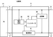
- FIG. 2 is a block diagram illustrating a configuration example of the slave unit 8 according to the comparative example.
- the configuration example of FIG. 2 shows the slave unit 8 coupled to the solar cell panel P1 on the highest potential side of the solar cell string 10.
- 2 includes a current detection circuit 81, a voltage detection circuit 82, a controller 83, and a transmitter 84.
- the current detection circuit 81 detects the output current of the solar battery panel P1.
- the current detection circuit 81 may be mounted using, for example, a Hall element or a resistor having a minute resistance value.
- the voltage detection circuit 82 is coupled between the DC power line 21 and the DC power line L1, and detects the output voltage of the solar battery panel P1.
- the voltage detection circuit 82 is coupled to the DC power line 21 and detects the voltage of the DC power line 21 with respect to a reference voltage (not shown) (for example, the voltage of the DC power line L1).
- the voltage detection circuit 82 may be coupled between the DC power line 21 and the DC power line L1, and may detect the output voltage of the solar cell panel P1.
- the controller 83 transmits the measurement data from the current and voltage detection circuits 81 and 82 to the parent device 9 via the transmitter 84. That is, the controller 83 collects measurement data from the current and voltage detection circuits 81 and 82, generates a digital transmission signal (transmission bit string) in which the measurement data is encoded, and supplies the digital transmission signal to the transmitter 84.
- the controller 83 may be implemented using, for example, a microcontroller (microprocessor) or a digital signal processor (DSP).
- the transmitter 84 communicates with the master unit 9 using power line communication technology. More specifically, the transmitter 84 has a line driver (amplifier), and superimposes the digital transmission signal as a current signal on the DC power lines 21 and L1.
- the line driver of the transmitter 84 is generally coupled to the two DC power lines 21 and L1 connected to the solar cell panel P1 in parallel with the solar cell panel P1.
- FIG. 3 shows an equivalent circuit of the photovoltaic power generation system according to the comparative example described with reference to FIGS.
- 3 is represented as a current source, and superimposes a current signal Itx ′ encoded with measurement data on a DC current path.
- mobile_unit 8 is connected in parallel with the solar cell panel P1 between the DC power lines 21 and L1.
- the current signal Itx ′ of the slave unit 8 is a closed circuit (loop) including the current Ip ′ flowing through the closed circuit (loop) including the solar battery panel P1, and the other solar battery panels P2 to P15 and the power conditioner 3. Is shunted to a current Ict ′ flowing through the.
- the current Ict ′ can be expressed by the following equation (1).
- Z1, Z2,..., And Z15 are the impedances of the solar cell panels P1 to P15
- Zin is the impedance of the power conditioner.
- the present invention has been made on the basis of the above findings by the inventors. Therefore, one of the objects of the present invention is to improve the communication performance between the slave unit and the master unit in a monitoring system that performs monitoring in units of solar cell panels.
- the solar power generation facility includes a solar cell string, first and second main power lines, and an inverter.
- the solar cell string includes a plurality of solar cell panels connected in series by a plurality of power lines.
- the first main power line is connected to a solar cell panel on the highest voltage side among the plurality of solar cell panels.
- the second main power line is connected to a solar cell panel on the lowest voltage side among the plurality of solar cell panels.
- the inverter acquires DC power generated by the solar cell string through a DC current path including the plurality of power lines, the first main power line, and the second main power line, and the DC power is AC power.
- the monitoring system is coupled to the slave unit according to the first aspect described above and the first or second backbone power line or both, and the first measurement is performed from the first slave unit. Includes the parent device that receives the data.
- the solar power generation system includes the monitoring system according to the second aspect described above and the solar power generation facility coupled to the monitoring system.
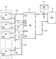
- FIG. 4 is a diagram illustrating a configuration example of the photovoltaic power generation system according to the present embodiment.
- the solar power generation system shown in FIG. 4 includes a solar power generation facility and its monitoring system.
- the configuration of the photovoltaic power generation facility of FIG. 4 is the same as that of the comparative example shown in FIG. That is, the solar power generation facility includes the solar cell string 10, the DC power lines 21 and 22, and the power conditioner 3.
- the solar cell string 10 includes a plurality of solar cell panels (PV) P1 to P15 connected in series by DC power lines L1 to L14.
- the number of solar cell panels included in the solar cell string 10 is arbitrary, and is not limited to 15 pieces shown in FIG.
- the solar cell string 10 and the power conditioner 3 are connected by two DC power lines 21 and 22.
- the DC power line 21 is a high voltage side power line
- the DC power line 22 is a low voltage side power line. That is, the DC power line 21 is connected to the solar cell panel P1 on the highest voltage side among the solar cell panels P1 to P15 included in the solar cell string 10.
- the DC power line 22 is connected to the solar cell panel P15 on the lowest voltage side.
- the power conditioner 3 acquires the DC power generated by the solar cell string 10 through the DC current path including the DC power lines 21 and 22 and the DC power lines L1 to L14.
- the power conditioner 3 has a DC / AC inverter function, and converts the DC power generated by the solar cell string 10 into AC power.
- the monitoring system of the present embodiment includes a slave unit (remote unit (RU)) 4 and a base unit (base unit (BU)) 5.
- mobile_unit 4 acquires the measurement data (for example, output voltage) measured separately about each of the solar cell panels P1-P15, and the current signal (that is, current signal in which measurement data is encoded) which shows the measurement data concerned ) Is superimposed on a DC current path (including DC power lines 21 and 22 and DC power lines L1 to L14) to which the solar cell string 10 and the power conditioner 3 are connected.
- the slave unit 4 is connected to the DC power lines 21 and 22 and terminals T21 and T22 connected to L1 to L14 as shown in FIG. And TL1 to TL14.
- the master unit 5 is coupled to the DC power line 21 or 22 or both, and is configured to communicate with the slave unit 4 and receive measurement data from the slave unit 4.
- the master unit 5 is coupled to the DC power line 21 by a current transformer (current transformer (CT)) 6.
- CT6 loads an induced current generated in the secondary coil in accordance with a change in magnetic flux (that is, change rate of magnetic flux or time differentiation) generated in the core by the current flowing through the electric wire (that is, the primary coil) passing through the annular core. Output as a voltage signal by flowing through a resistor.
- CT6 current transformer
- the base unit 5 only needs to be coupled to a DC current path that connects the solar cell string 10 and the power conditioner 3, and may be coupled to the DC power line 22 via CT6.
- the coupling circuit (coupling ⁇ circuit) for coupling the master unit 5 to the DC power path is not limited to CT6.
- base unit 5 may be coupled to DC power lines 21 and 22 and detect a voltage change between DC power lines 21 and 22.
- the transmission method between the slave unit 4 and the master unit 5 may be baseband transmission that does not use subcarriers, or may be carrier-modulated transmission that performs subcarrier modulation.
- the slave unit 4 may generate a transmission signal by, for example, NRZ (Non Return to Zero) encoding that directly assigns a transmission bit string to two current levels.
- NRZ Non Return to Zero
- handset 4 may map a transmission bit string to a transmission symbol string and transmit a current signal indicating a current change according to the transmission symbol string.
- the modulation scheme in the case of employing carrier modulation transmission is not limited to a specific scheme, and any modulation scheme that can be employed in power line communication can be used.
- the handset 4 uses a DC power line to indicate a current change indicating a carrier wave modulated using On Off Keying (OOK), Amplitude Shift Keying (ASK), Frequency Shift Keying (FSK), or Phase Shift Keying (PSK). It may be superimposed on the direct current flowing through
- OOK On Off Keying
- ASK Amplitude Shift Keying
- FSK Frequency Shift Keying
- PSK Phase Shift Keying
- the master unit 5 may communicate with a plurality of slave units 4 coupled to the plurality of solar cell strings 10.
- the multiple access method between the child device 4 and the parent device 5 is not limited to a specific method, and any modulation method that can be employed in power line communication can be used.
- the multiple access method employed in this embodiment is Spread Spectrum Multiple Access (SSMA), Time Division Multiple Access (TDMA), Frequency Division Multiple Access (FDMA), or Orthogonal Frequency Division Multiple Access (OFDMA), or these. Any combination of the above may be used.
- FIG. 5 is a block diagram illustrating a configuration example of the slave unit 4 according to the present embodiment.
- the slave unit 4 includes a current detection circuit 41, a switch circuit 42, a voltage detection circuit 43, a controller 44, and a transmitter 45.
- the current detection circuit 41 is coupled to the DC power line 22 and detects the output current of the solar battery panel P15.
- the current detection circuit 41 may be coupled to the DC power line 21 and detect a current flowing through the solar cell panel P1.
- the current detection circuit 41 may be mounted using a Hall element or a resistor having a minute resistance value.
- the switch circuit 42 is disposed between the terminals T21 and TL1 to TL14 and the voltage detection circuit 43.
- the switch circuit 42 switches the connection destination of the voltage detection circuit 43 between the solar battery panels P1 to P15.
- the voltage detection circuit 42 detects the voltage at the terminal selected by the switch circuit 42.
- the voltage detection circuit 42 may detect a relative voltage with respect to a reference voltage (not shown) (for example, the voltage of the DC power line 22).
- the voltage detection circuit 42 may measure the output voltage of each solar cell panel.
- the switch circuit 42 may be disposed between the terminals T21 and T22 and TL1 to TL14 and the voltage detection circuit 43.
- the switch circuit 42 may connect adjacent terminal pairs (for example, a pair of terminals T21 and TL1, a pair of terminals TL1 and TL2, or a pair of terminals TL14 and T22) to the voltage detection circuit 43 in order.
- adjacent terminal pairs for example, a pair of terminals T21 and TL1, a pair of terminals TL1 and TL2, or a pair of terminals TL14 and T22.
- the controller 44 transmits measurement data obtained by the current and voltage detection circuits 41 and 43 to the parent device 9 via the transmitter 45. That is, the controller 44 collects measurement data from the current and voltage detection circuits 41 and 43, generates a digital transmission signal (transmission bit string) in which the measurement data is encoded, and supplies the digital transmission signal to the transmitter 45.
- the data format and transmission frame format for transmitting measurement data are not particularly limited. For example, measurement data relating to a plurality of solar battery panels P1 to P15 may be transmitted together in one transmission frame, or may be divided and transmitted using a plurality of transmission frames.
- the controller 44 may be implemented using, for example, a microcontroller (microprocessor) or a digital signal processor (DSP).
- the transmitter 45 communicates with the parent device 5 using power line communication technology.
- the transmitter 45 has a line driver (amplifier), and superimposes a digital transmission signal on the DC power lines 21 and 22 as a current signal.
- Transmitter 45 is coupled between DC power lines 21 and 22 in parallel with solar cell panels P1-P15. More specifically, the transmitter 45 may include a line driver and a coupling circuit that couples the line driver to the DC power lines 21 and 22.
- the coupling circuit includes, for example, a transformer.
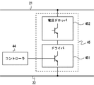
- FIG. 6 shows a configuration example of the transmitter 45.
- the transmitter 45 shown in FIG. 6 includes a driver circuit 451 and a voltage dropper circuit 452 connected between the DC power lines 21 and 22.
- the driver circuit 451 is a constant current circuit using an NPN transistor, for example. In this case, since the driver circuit 451 operates at a constant current according to the voltage signal supplied from the controller 44 to the base, a current change is superimposed between the DC power lines 21 and 22 connected through the voltage dropper circuit 452.
- the voltage signal supplied from the controller 44 to the base of the driver circuit 451 is, for example, a pulse signal and represents a transmission bit string.
- the voltage dropper circuit 452 is configured by a switching element such as a transistor, for example, and steps down the high voltage between the DC power lines 21 and 22 to an appropriate voltage of the driver circuit 451.
- FIG. 7 shows an equivalent circuit of the photovoltaic power generation system according to the present embodiment described with reference to FIGS.
- the slave unit 4 in FIG. 7 is represented as a current source, and superimposes a current signal Itx encoded with measurement data individually measured for each of the solar battery panels P1 to P15 on a DC current path.
- the slave unit 4 is connected between the DC power lines 21 and 22 in parallel with the solar cell panels P1 to P15. Therefore, the current signal Itx of the slave unit 4 is divided into a current Ip flowing through a closed circuit (loop) including the solar battery panels P1 to P15 and a current Ict flowing through a closed circuit (loop) including the power conditioner 3.
- the current Ict can be expressed by the following equation (2).
- Z1, Z2,..., And Z15 are the impedances of the solar cell panels P1 to P15, respectively, and Zin is the impedance of the power conditioner, as in the above-described equation (1). That is, in contrast to the comparative example of FIG. 3 and Equation (1), the shunt ratio of the current signal Ict flowing through the closed circuit including the power conditioner 3 increases as the number of solar cell panels included in the solar cell string 10 increases. growing.
- the internal impedance Zin of the power conditioner 3 is generally sufficiently smaller than the impedance of the solar cell string 10 (that is, the sum of Z1 to Z15). Therefore, it is considered that almost all of the current signal Itx output from the transmitter 45 flows through a closed circuit including the power conditioner 3. Therefore, the communication performance (communication quality) between the subunit
- the slave unit 4 of the present embodiment can measure the measurement data (for example, the output voltage of each panel) individually measured for each of the solar cell panels P1 to P15 included in the solar cell string 10. Is superimposed on the DC current path including the DC power lines 21 and 22 and the DC power lines L1 to L14. Further, the slave unit 4 has a transmitter 45 coupled in parallel to the solar battery panels P1 to P15, and the transmitter 45 superimposes a current signal on the direct current path. Therefore, the monitoring system including the slave unit 4 and the slave unit 4 according to the present embodiment can improve the communication performance between the slave unit 4 and the master unit 5 when monitoring in units of solar battery panels.
- the measurement data for example, the output voltage of each panel
- the transmitter 45 of the slave unit 4 may not be coupled in parallel to all of the solar cell panels P1 to P15, and may be coupled in parallel to more than one of the solar cell panels P1 to P15. .
- the transmitter 45 of the slave unit 4 may be coupled between the DC power lines 21 and L14 in parallel with the solar battery panels P1 to P14.
- the current signal Ict2 flowing through the closed circuit (loop) including the solar battery panel P15 and the power conditioner 3 in accordance with the law of diversion can be expressed by the following equation (3).
- the shunt ratio of the current signal Ict2 shown in the equation (3) is larger than the shunt ratio of the current signal Ict ′ shown in the equation (1). Therefore, the communication performance between the slave unit 4 and the master unit 5 can be improved as compared with the comparative example described with reference to FIGS.
- one slave unit 4 acquires measurement data related to each of the plurality of solar battery panels and transmits the measurement data to the master unit 5. Therefore, the number of slave units can be reduced as compared to the case of using a plurality of slave units associated with each of the plurality of solar cell panels as in the comparative example. That is, this embodiment can reduce the number of slave units in a monitoring system that performs monitoring in units of solar battery panels.
- the configuration in which the connection destination of the voltage detection circuit 43 is switched between the solar battery panels P1 to P15 using the switch circuit 42 is shown.
- the output voltage of each of the plurality of solar battery panels can be individually measured using one voltage detection circuit 43.
- the configuration example in FIG. 5 is only an example.
- mobile_unit 4 may have several voltage detection circuit 43, and the switch circuit 42 may be abbreviate
- mobile_unit 4 may have a sensor (for example, temperature sensor) different from the electric current detection circuit 41 and the voltage detection circuit 43.
- FIG. 8 is a block diagram illustrating a configuration example of the photovoltaic power generation system according to the present embodiment.
- the system of FIG. 8 has a plurality of solar cell strings 10 including solar cell strings 10A to 10D.
- Each solar cell string 10 has a plurality of solar cell panels P1, P2, P3,... Connected in series.
- the plurality of solar cell strings 10 are connected in parallel by a plurality of DC power lines 21 including DC power lines 21A to 21D.
- the power conditioner 3 acquires the DC power generated by the plurality of solar cell strings 10 via the plurality of DC power lines 21 connected in parallel, and converts this into AC power.
- a current IA indicates a current flowing through the DC power line 21A, that is, a current flowing through the solar cell string 10A.
- the currents IB, IC, and ID are the current that flows through the DC power line 21B (that is, the solar cell string 10B), the current that flows through the DC power line 21C (that is, the solar cell string 10C), and the DC power line 21D (that is, the solar cell string 10D).
- a current I is a combined current of direct currents flowing through the plurality of solar cell strings 10 including the currents IA to ID, and indicates a direct current supplied to the power conditioner 3.
- FIG. 8 shows only the high-voltage side DC power line 21, and the illustration of the DC power line 22 connecting the low-voltage side of each solar cell string 10 and the power conditioner 3 is omitted. Further, although four solar cell strings 10A to 10D are shown in FIG. 8, the solar power generation system of FIG. 8 may have more solar cell strings 10, or two or Only three solar cell strings 10 may be provided.
- FIG. 8 shows two multiple access communication systems.
- One multiple-access communication system includes a master unit 5A and a plurality of slave units 4A and 4B connected to solar cell strings 10A and 10B (power lines 21A and 21B).
- the other multiple access communication system includes a master unit 5B and a plurality of slave units 4C and 4D connected to the solar cell strings 10C and 10D (power lines 21C and 21D).
- the multiple access method employed in the present embodiment is not limited to a specific method, and any modulation method that can be employed in power line communication can be used.
- the multiple access method employed in this embodiment may be SSMA (DS-CDMA), TDMA, FDMA, OFDMA, or any combination thereof.
- slave unit 4 and the master unit 5 may be the same as those in the first embodiment described above.
- one slave unit 4 is coupled to each solar cell string 10, and one slave unit 4 includes a plurality of slave units 4 included in the solar cell string 10. Monitor solar panels.
- two or more slave units 4 may be coupled to at least one of the plurality of solar cell strings 10.
- a set of slave units 4 connected to one solar cell string 10 may be referred to as a “slave unit (RU) group”.
- a large-scale solar power generation system called a mega solar system uses a huge number of solar cell panels and solar cell strings. Therefore, in order to monitor many solar battery panels, many slave units 4 are required.
- the number of multiple access such as SSMA, TDMA, FDMA, OFDMA, etc., has limited resources (ie, time, frequency, or spreading code, or a combination thereof) used exclusively for multiple access, and multiple access
- resources ie, time, frequency, or spreading code, or a combination thereof
- a plurality of master units 5 for example, master units 5A and 5B
- Using a plurality of base units 5 means using a plurality of multiple access communication systems. If the same resource can be shared (or reused) among a plurality of multiple access communication systems, the above-mentioned problem due to the upper limit of the number of resources may be solved.
- the photovoltaic power generation system as shown in FIG. 8 has a configuration in which a plurality of DC power lines 21A to 21D each connected to the solar cell string 10 are connected in parallel. Therefore, the signal of one multi-access communication system including the master unit 5B shown in FIG. 8 is transmitted through the plurality of DC power lines 21A to 21D connected in parallel to the other multi-access communication system including the master unit 5A. Interfering with the signal.
- the same resource ie, time, frequency, or spreading code, or a combination thereof
- CT6A and 6B which concern on this embodiment are the specific examples of the electric current detection part which outputs the electrical signal which shows the change of the difference electric current between the 1st electric current which flows through a 1st electric wire, and the 2nd electric current which flows through a 2nd electric wire. It is.
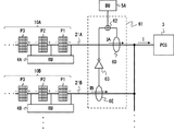
- the CT 6A shown in FIG. 8 generates an electric signal indicating a change in the difference current between the current IA flowing through the power line 21A and the current IB flowing through the power line 21B.
- the two power lines 21A and 21B penetrate the CT6A annular core in opposite directions. Therefore, the direct current IA flowing through the power line 21A from the solar cell string 10A toward the power conditioner 3 passes through the annular core of CT6A from the left side to the right side of the sheet of FIG.
- the direct current IB flowing through the power line 21B from the solar cell string 10B toward the power conditioner 3 passes through the annular core of CT6A from the right side to the left side in FIG.
- the change of the currents IA and IB is in reverse phase means that one of the currents IA and IB increases while the other decreases, in other words, the sign of the time derivative (ie, slope) of the currents IA and IB is Means opposite to each other.
- the CT 6A is used to generate an electrical signal corresponding to a change in the difference current between the currents IA and IB, and this is supplied to the parent device 5A.
- the master unit 5A receives the transmission signals of the two slave units 4A and 4B (or two slave unit groups) connected to the power lines 21A and 21B, and other units connected to the other power lines 21C and 21D.
- the transmission signals of the slave units 4C and 4D (or the slave unit group) can be substantially canceled.
- substantially cancel means that it is not necessary to cancel completely so that the transmission signals of the other slave units 4C and 4D (or slave unit groups) become zero.
- substantially cancel means that the transmission signal levels of the slave units 4C and 4D (or slave unit group) connected to the power lines 21C and 21D are two slave units connected to the power lines 21A and 21B. This means that the transmission signals of 4A and 4D (or two child device groups) are sufficiently small to be received at a predetermined quality (for example, SNR (Signal to Noise Ratio), code error rate).
- a predetermined quality for example, SNR (Signal to Noise Ratio), code error rate
- the direct current IA changes according to the current signal.
- the flow of charges (that is, electrons) resulting from the change in the current IA gives a reverse phase change to the other power lines 21 including the power line 21B.
- the direct current IA increases due to the superposition of the current signal by the slave unit 4A, a large number of electrons are drawn into the power line 21A, so that the flow of electrons on the power line 21B (and the other power lines 21C and 21D) decreases.
- the electrical signal output from the CT 6A that is, the electrical signal indicating the change in the difference current between the direct currents IA and IB reflects the increase or decrease in the direct current IA.
- base station 5A can receive the transmission signal of the subunit
- Transmission of the slave unit 4B (or slave unit group) connected to the DC power line 21B can be considered in the same manner as transmission of the slave unit 4A. That is, when the handset 4B transmits a current signal to the power line 21B, the direct current IB increases or decreases due to the superposition of the current signal. The change in the direct current IA (and the currents IC and ID flowing through other power lines) due to the increase / decrease in the direct current IB is opposite to the change in the current IB. Therefore, the master unit 5A can receive the transmission signal of the slave unit 4B using the output signal of the CT 6A indicating the change in the difference current between the direct currents IA and IB.
- the direct currents IC and ID flowing through the power lines 21C and 21D are increased or decreased by transmission of the slave units 4C and 4D (or the slave unit group) connected to the power lines 21C and 21D, the effect is the direct current flowing through the electric wires 21A and 21B. Appears in phase in IA and IB.
- the direct current IC of the power line 21C increases due to the superposition of the current signal by the slave unit 4C, a large number of electrons are drawn into the power line 21C, so that the flow of electrons in the power lines 21A and 21B decreases. For this reason, changes in the direct currents IA and IB due to the increase and decrease in the direct current IC are in phase with each other.
- the change in the direct currents IA and IB due to the increase or decrease in the direct current IC is substantially canceled without appearing in the output signal of the CT 6A indicating the change in the difference current between the currents IA and IB.
- the current signal transmitted to the power line 21D by the slave unit 4D is substantially canceled without appearing in the output signal of the CT 6A.
- base unit 5A can receive the transmission signals of slave units 4A and 4B without being affected by the transmission signals of slave units 4C and 4D.
- the two slave units 4A and 4B (or two slave unit groups) that use the power lines 21A and 21B are the other slave units 4C and 4D that use the other power lines 21C and 21D.
- Resources can be shared with This is because interference of transmission signals (current signals) from the other slave units 4C and 4D is substantially canceled in the difference current between the direct currents IA and IB.
- noise generated by devices related to the photovoltaic power generation system for example, switching noise of the power conditioner 3, modulation components due to the maximum operating point tracking operation of the power conditioner 3, and the like flow through the power line 21. Superimposed on the current. The influence of the noise of the power conditioner 3 appears in phase on the power lines 21A to 21D connected in parallel. Therefore, the base unit 5A can suppress a decrease in reception quality due to noise of the power conditioner 3 by using the electric signal output from the CT 6A. This is because the noise of the power conditioner 3 is substantially canceled in the difference current between the direct currents IA and IB.
- CT6B produces
- CTs 6A and 6B shown in FIG. 8 is merely an example for detecting a change in the difference current between the currents flowing through the two power lines 2.
- Another arrangement example of CT6 will be described in another embodiment described later.
- ⁇ Third Embodiment> a modified example in which the number of power lines 21 penetrating the core of CT 6 is different from that in FIG. 8 will be described.
- the second embodiment an example is shown in which two DC power lines 21 (for example, 21A and 21B) are passed through the cores of one CT6 (for example, 6A) in opposite directions. Thereby, the directions of two direct currents (for example, IA and IB) passing through the core of CT6A are opposite to each other.
- the number of power lines 21 that pass through the core of one CT 6 may be an even number of four or more. That is, out of 2N (N is a positive integer) power lines 21, N power lines 21 are passed through the CT6 core in one direction, and the other N power lines 21 are passed through the CT6 core in the opposite direction. Good.
- FIG. 9 shows an example in which four power lines 21A to 21D are arranged so as to pass through one CT6C core. Specifically, the power lines 21A and 21C pass through the annular core of CT6C from the left side to the right side of the sheet of FIG. On the other hand, the power lines 21B and 21D pass through the annular core of CT6C from the right side to the left side in FIG.
- FIGS. 10A and 10B show first and second configuration examples of the photovoltaic power generation system according to the present embodiment.
- the configuration examples of FIGS. 10A and 10B use current detection units 60 and 61 including two CT6D and 6E instead of one CT6A.
- the power line 21A passes through the CT6D core
- the power line 21B passes through the CT6E core.
- the direction in which the power line 21B penetrates the CT6E core is opposite to the direction in which the power line 21A penetrates the CT6D core.
- the direction in which the direct current IA passes through CT6D and the direction in which the direct current IB passes through CT6E are opposite to each other.
- the adder 62 in FIG. 10A supplies a signal obtained by adding the output signals of CT6D and 6E to the parent device 5A.
- the signal obtained by adding the output signals of CT6D and 6E indicates a change in the difference current between the two currents IA and IB flowing through the two power lines 2A and 2B. Therefore, the master unit 5A can identify and receive the bit strings transmitted from the two slave units 4A and 4B (or two slave unit groups) using the output signal of the adder 62.
- the direct currents IA and IB pass through the CTs 6D and 6E in the same direction. Therefore, in FIG. 10B, the output signal of CT6E is inverted using the inverting amplifier 63.
- the adder 62 in FIG. 10B adds the CT6D output signal to the inverted signal of the CT6E output signal.
- the output signal of the adder 62 indicates a change in the difference current between the two currents IA and IB flowing through the two power lines 21A and 21B. Therefore, the master unit 5A can identify and receive the bit strings transmitted from the two slave units 4A and 4B (or two slave unit groups) using the output signal of the adder 62. Further, as a method not using the inverting amplifier 63 shown in FIG. 10B, when the outputs of CT6D and CT6E are connected to the adder 62, the polarities may be reversed.
- the configuration example of the second and third embodiments is the CT.
- the number can be reduced.
- 10A and 10B if there is a characteristic difference between the two CTs 6D and 6E, the reception quality of the base unit 5A may be deteriorated.
- the difference current (combined current) of the currents flowing through the plurality of power lines 21 is detected by one CT6. There is an advantage that reception quality degradation of 5 does not occur in principle.
- the CTs 6A to 6E are coupled to the DC power line 21 on the high voltage side.
- the CTs 6A to 6E may be coupled to the DC power line 22 on the low voltage side, which is not shown in FIGS. 8, 9, 10A, and 10B.
- an example is shown in which an even number of power lines 21 are passed through the core of CT6.
- the magnification ratio is passed through the CT6 core so that the ratio is the reciprocal of the number of power lines passing through CT6. What is necessary is just to change the frequency
- the master unit 5A can identify and receive the bit strings transmitted from the two slave units 4A and 4B (or two slave unit groups) using the output signal of the adder 62. Also, in the case of handling an odd number of three or more power lines 21 in the configuration of FIG. 10A described in the fourth embodiment, instead of passing the electric wire twice through the annular core, the annular core is reversed. What is necessary is just to double the load resistance of passing CT6. Thereby, the electric signal sent out from the child device 4 connected to the other power line input to the adder 62 can be canceled.
- the example in which the current transformer is used to detect the change in the difference current between the currents flowing through the two power lines 2 has been described.
- another current detection unit that can detect a change in the difference current between the currents flowing through the two power lines 21 may be used.
- a current detection unit including a Hall element or a shunt resistor may be used.
- the Hall element or the shunt resistor is used, the influence of the difference in generated current between the plurality of solar cell strings 10 (that is, a pure DC component or an average value) is removed, resulting from the current signals of the plurality of slave units 4.
- an analog differentiating circuit or a digital differentiating circuit may be used.
- the digital differentiation circuit may be integrated with a receiver (for example, a signal processing unit) included in the parent device 5.
Landscapes
- Engineering & Computer Science (AREA)
- Power Engineering (AREA)
- Remote Monitoring And Control Of Power-Distribution Networks (AREA)
- Photovoltaic Devices (AREA)
- Supply And Distribution Of Alternating Current (AREA)
- Cable Transmission Systems, Equalization Of Radio And Reduction Of Echo (AREA)
Abstract
監視システムは、子機(4)および親機(5)を含む。子機(4)は、太陽電池ストリング(10)を構成している複数の太陽電池パネル(P1~P15)に含まれる1より多い太陽電池パネルの各々について個別に計測された計測データを示す電流信号を、直流電流経路に重畳する。直流電流経路は、複数の電力線(L1~L14)、第1の基幹電力線(21)、及び第2の基幹電力線(22)を含む。親機(5)は、第1の基幹電力線(21)若しくは前記第2の基幹電力線(22)又はこれら両方に結合され、子機(4)から計測データを受信する。これにより、例えば、太陽電池パネル単位の監視を行う監視システムにおける子機と親機の間の通信性能を改善できる。
Description
本出願は、太陽光発電設備のための監視システムに関し、特に、太陽電池パネルにより生成される電力を伝送する直流電力線を用いて通信する子機及び監視システムに関する。
一般的な太陽光発電設備(太陽光発電システムとも呼ばれる)は、複数の太陽電池パネル(太陽電池モジュールとも呼ばれる)が直列および並列に接続された太陽電池アレイを有する。太陽電池アレイは、太陽電池パネルが直列に接続された太陽電池ストリングが並列に接続された構成を持つ。太陽電池アレイによって生成された直流電力は、直流電力線を介してパワーコンディショナに送られる。パワーコンディショナは、DC/ACインバータを有し、直流電力を交流電力に変換する。
電流計、電圧計、又は電力計等のセンサを用いて太陽光発電設備を監視するシステム(いわゆるセンサネットワーク)が知られている。太陽光発電設備のためのこのような監視システムは、センサによって取得された計測データを送信する子機と、計測データを子機から受信する親機を含む。子機は、例えば、太陽電池パネル(太陽電池モジュール)、太陽電池ストリング、又は太陽電池アレイと結合して配置される。発電状況の監視は、太陽電池ストリング単位又は太陽電池アレイ単位で行うこともできる。
特許文献1及び2は、太陽電池パネル単位での監視のために、太陽電池パネル毎に子機が配置された構成を持つ監視システムを開示している。さらに、太陽光発電システムの場合、太陽電池パネルによって生成された電力をパワーコンディショナに供給するための直流電力線を子機と親機の間の通信のための通信路として利用できる。特許文献1及び2に開示された監視システムは、直流電力線を子機と親機の間の通信のための通信路として利用する。
例えば、特許文献1の監視システムでは、子機は太陽電池パネル毎に配置される。子機は、太陽電池パネルに関する監視情報がエンコードされた伝送フレームを生成し、予め割り当てられた拡散符号を用いて伝送フレームの各ビットを直接拡散し、これにより送信信号を生成する。そして、子機は、送信信号を電流信号として送信する。言い換えると、子機は、送信信号に応じた電流変化を、太陽光発電パネルに接続された直流電力線に重畳する。特許文献1の親機は、一例において、パワーコンディショナの近くに配置される。親機は、複数の子機から送信された電流信号を、高電圧側及び低電圧側の2本の電力線間の電圧変化として検出する。そして、通信親機は、検出した受信信号に対する逆拡散処理を行うことによって、各通信子機から送信されたビット列を識別して受信する。これにより、親機は、太陽電池パネル毎の発電状況を監視する。
太陽光発電設備の発電状況を詳細に監視するためには、太陽電池パネル単位で発電状況を監視できることが好ましい。したがって、特許文献1及び2に開示された監視システムは、太陽電池パネル毎に子機が配置された構成を採用している。しかしながら、本件の発明者等は、太陽電池パネル毎に子機が配置された構成において、子機と親機との間の通信性能が低下する問題があることを見出した。以下では、本件発明者等が検討した比較例に従って当該問題を説明する。
<比較例の説明>
図1は、比較例に係る太陽光発電システムの構成例を示している。図1の太陽光発電システムは、太陽光発電設備およびその監視システムを含む。太陽光発電設備は、太陽電池ストリング10、直流電力線21及び22、並びにパワーコンディショナ3を含む。太陽電池ストリング10は、直流電力線L1~L14によって直列に接続された複数の太陽電池パネル(photovoltaic solar panel (PV))P1~P15を含む。太陽電池ストリング10とパワーコンディショナ3の間は2本の直流電力線21及び22によって接続されている。直流電力線21は高電圧側の電力線であり、直流電力線22は、低電圧側の電力線である。パワーコンディショナ3は、太陽電池ストリング10によって生成された直流電力を、直流電力線21及び22並びに直流電力線L1~L14を含む直流電流経路を通じて取得する。パワーコンディショナ3は、DC/ACインバータ機能を有し、太陽電池ストリング10によって生成された直流電力を交流電力に変換する。
図1は、比較例に係る太陽光発電システムの構成例を示している。図1の太陽光発電システムは、太陽光発電設備およびその監視システムを含む。太陽光発電設備は、太陽電池ストリング10、直流電力線21及び22、並びにパワーコンディショナ3を含む。太陽電池ストリング10は、直流電力線L1~L14によって直列に接続された複数の太陽電池パネル(photovoltaic solar panel (PV))P1~P15を含む。太陽電池ストリング10とパワーコンディショナ3の間は2本の直流電力線21及び22によって接続されている。直流電力線21は高電圧側の電力線であり、直流電力線22は、低電圧側の電力線である。パワーコンディショナ3は、太陽電池ストリング10によって生成された直流電力を、直流電力線21及び22並びに直流電力線L1~L14を含む直流電流経路を通じて取得する。パワーコンディショナ3は、DC/ACインバータ機能を有し、太陽電池ストリング10によって生成された直流電力を交流電力に変換する。
監視システムは、複数の子機(remote unit (RU))8及び親機(base unit (BU))9を含む。太陽電池パネル単位の監視を行うために、太陽電池パネル(photovoltaic panel (PV))P1~P15のそれぞれに子機8が設けられている。子機8は、センサによって取得された計測データ(例えば、電流、電圧、温度など)を送信する。具体的には、子機8は、計測データを示す電流信号(つまり、計測データがエンコードされている電流信号)を、太陽電池ストリング10及びパワーコンディショナ3が接続された直流電流経路に重畳する。
親機9は、複数の子機8と通信し、複数の子機8の各々から計測データを受信する。図1の例では、親機9は、カレントトランス(current transformer (CT))6によって直流電力線21に結合されている。
図2は、比較例に係る子機8の構成例を示すブロック図である。図2の構成例は、太陽電池ストリング10のうち最も高電位側の太陽電池パネルP1に結合された子機8を示している。図2の子機8は、電流検出回路81、電圧検出回路82、コントローラ83、及び送信機84を含む。電流検出回路81は、太陽電池パネルP1の出力電流を検出する。電流検出回路81は、例えば、ホール素子、又は微小抵抗値の抵抗器を用いて実装されてもよい。電圧検出回路82は、直流電力線21と直流電力線L1の間に結合され、太陽電池パネルP1の出力電圧を検出する。電圧検出回路82は、直流電力線21に結合され、図示しない基準電圧(例えば、直流電力線L1の電圧)に対する直流電力線21の電圧を検出する。電圧検出回路82は、直流電力線21と直流電力線L1の間に結合され、太陽電池パネルP1の出力電圧を検出してもよい。
コントローラ83は、電流及び電圧検出回路81及び82による計測データを送信機84を介して親機9に送信する。すなわち、コントローラ83は、電流及び電圧検出回路81及び82による計測データを収集し、計測データがエンコードされたデジタル送信信号(送信ビット列)を生成し、デジタル送信信号を送信機84に供給する。コントローラ83は、例えば、マイクロコントローラ(マイクロプロセッサ)又はDigital Signal Processor(DSP)を用いて実装されてもよい。
送信機84は、電力線通信技術を用いて親機9と通信する。具体的に述べると、送信機84は、ラインドライバ(アンプ)を有し、デジタル送信信号を電流信号として直流電力線21及びL1に重畳する。送信機84のラインドライバは、一般的に、太陽電池パネルP1と並列に、太陽電池パネルP1に接続された2本の直流電力線21及びL1に結合される。
図3は、図1及び2を用いて説明した比較例に係る太陽光発電システムの等価回路を示している。図3では、太陽電池パネルP1に結合された子機8のみを示している。図3の子機8は、電流源として表記されており、計測データがエンコードされた電流信号Itx’を直流電流経路に重畳する。子機8は、直流電力線21及びL1の間に、太陽電池パネルP1と並列に接続されている。したがって、子機8の電流信号Itx’は、太陽電池パネルP1を含む閉回路(ループ)を流れる電流Ip’と、その他の太陽電池パネルP2~P15並びにパワーコンディショナ3を含む閉回路(ループ)を流れる電流Ict’に分流される。分流の法則に従って、電流Ict’は、以下の式(1)により表わすことができる。

ここで、Z1、Z2、・・・、及びZ15は太陽電池パネルP1~P15それぞれのインピーダンスであり、Zinはパワーコンディショナのインピーダンスである。式(1)から理解されるように、太陽電池ストリング10に含まれる太陽電池パネル数が大きくなるほど、太陽電池パネルP2~P15並びにパワーコンディショナ3を含む閉回路に流れる電流信号Ict’の分流比が小さくなる。親機9はパワーコンディショナ側に配置されるから、Ict’が小さくなることは子機8と親機9の間の通信性能(通信品質)の低下を招くおそれがある。
本件発明は、発明者等による上述の知見に基づいてなされたものである。したがって、本件発明の目的の1つは、太陽電池パネル単位の監視を行う監視システムにおける子機と親機の間の通信性能を改善することである。
第1の態様では、太陽光発電設備のための監視システムで使用される子機が提供される。ここで、前記太陽光発電設備は、太陽電池ストリング、第1及び第2の基幹電力線、並びにインバータを含む。前記太陽電池ストリングは、複数の電力線によって直列に接続された複数の太陽電池パネルを含む。前記第1の基幹電力線は、前記複数の太陽電池パネルのうち最も高電圧側の太陽電池パネルに接続される。前記第2の基幹電力線は、前記複数の太陽電池パネルのうち最も低電圧側の太陽電池パネルに接続される。前記インバータは、前記太陽電池ストリングによって生成される直流電力を、前記複数の電力線、前記第1の基幹電力線、及び前記第2の基幹電力線を含む直流電流経路を通じて取得し、前記直流電力を交流電力に変換する。そして、本態様に係る子機は、前記複数の太陽電池パネルに含まれる1より多い太陽電池パネルの各々について個別に計測された計測データを遠隔に配置された親機に送信するために、前記計測データを示す電流信号を前記直流電流経路に重畳する送信機を有する。
第2の態様では、監視システムは、上述した第1の態様に係る子機と、前記第1若しくは第2の基幹電力線又はこれら両方に結合され、前記第1の子機から前記第1の計測データを受信する親機を含む。
第3の態様では、太陽光発電システムは、上述した第2の態様に係る監視システムと、前記監視システムに結合される前記太陽光発電設備を含む。
上述した態様によれば、太陽電池パネル単位の監視を行う監視システムにおける子機と親機の間の通信性能を改善することができる。
以下では、具体的な実施形態について、図面を参照しながら詳細に説明する。各図面において、同一又は対応する要素には同一の符号が付されており、説明の明確化のため、必要に応じて重複説明は省略される。
<第1の実施形態>
図4は、本実施形態に係る太陽光発電システムの構成例を示す図である。図4に示された太陽光発電システムは、太陽光発電設備およびその監視システムを含む。図4の太陽光発電設備の構成は、図1に示した比較例と同様である。すなわち、太陽光発電設備は、太陽電池ストリング10、直流電力線21及び22、並びにパワーコンディショナ3を含む。太陽電池ストリング10は、直流電力線L1~L14によって直列に接続された複数の太陽電池パネル(photovoltaic solar panel (PV))P1~P15を含む。太陽電池ストリング10に含まれる太陽電池パネル数は任意であり、図4に示された15個に限定されない。
図4は、本実施形態に係る太陽光発電システムの構成例を示す図である。図4に示された太陽光発電システムは、太陽光発電設備およびその監視システムを含む。図4の太陽光発電設備の構成は、図1に示した比較例と同様である。すなわち、太陽光発電設備は、太陽電池ストリング10、直流電力線21及び22、並びにパワーコンディショナ3を含む。太陽電池ストリング10は、直流電力線L1~L14によって直列に接続された複数の太陽電池パネル(photovoltaic solar panel (PV))P1~P15を含む。太陽電池ストリング10に含まれる太陽電池パネル数は任意であり、図4に示された15個に限定されない。
太陽電池ストリング10とパワーコンディショナ3の間は2本の直流電力線21及び22によって接続されている。直流電力線21は高電圧側の電力線であり、直流電力線22は、低電圧側の電力線である。つまり、直流電力線21は、太陽電池ストリング10に含まれる太陽電池パネルP1~P15のうち最も高電圧側の太陽電池パネルP1に接続される。一方、直流電力線22は、最も低電圧側の太陽電池パネルP15に接続される。パワーコンディショナ3は、太陽電池ストリング10によって生成された直流電力を、直流電力線21及び22並びに直流電力線L1~L14を含む直流電流経路を通じて取得する。パワーコンディショナ3は、DC/ACインバータ機能を有し、太陽電池ストリング10によって生成された直流電力を交流電力に変換する。
本実施形態の監視システムは、子機(remote unit (RU))4及び親機(base unit (BU))5を含む。子機4は、太陽電池パネルP1~P15の各々について個別に計測された計測データ(例えば、出力電圧)を取得し、当該計測データを示す電流信号(つまり、計測データがエンコードされている電流信号)を、太陽電池ストリング10及びパワーコンディショナ3が接続された直流電流経路(直流電力線21及び22並びに直流電力線L1~L14を含む)に重畳するよう構成されている。子機4は、太陽電池ストリング10に含まれる太陽電池パネルP1~P15を監視するために、図4に示されるように、直流電力線21、22、並びにL1~L14に接続される端子T21、T22、並びにTL1~TL14を有してもよい。
親機5は、直流電力線21若しくは22又はこれら両方に結合され、子機4と通信し、子機4から計測データを受信するよう構成されている。図4の例では、親機5は、カレントトランス(current transformer (CT))6によって直流電力線21に結合されている。CT6は、環状コアを貫通する電線(つまり一次側コイル)を流れる電流がコアに生じさせる磁束の変化(つまり磁束の変化率又は時間微分)に応じて二次側コイルに発生する誘導電流を負荷抵抗に流すことで電圧信号として出力する。なお、親機5は、太陽電池ストリング10とパワーコンディショナ3を接続する直流電流経路に結合されていればよく、CT6を介して直流電力線22に結合されてもよい。また、親機5を直流電力経路に結合するための結合回路(coupling circuit)は、CT6に限られない。例えば、親機5は、直流電力線21及び22に結合され、直流電力線21及び22の間の電圧変化を検出してもよい。
子機4と親機5の間の伝送方式は、サブキャリアを用いないベースバンド伝送でもよいし、サブキャリア変調を行う搬送波変調伝送(carrier-modulated transmission)でもよい。ベースバンド伝送が採用される場合、子機4は、例えば、送信ビット列を直接的に2つの電流レベルに割り当てるNRZ(Non Return to Zero)符号化によって送信信号を生成すればよい。また、搬送波変調伝送が採用される場合、子機4は、送信ビット列を送信シンボル列にマッピングし、送信シンボル列に応じた電流変化を示す電流信号を送信すればよい。搬送波変調伝送を採用する場合の変調方式は特定の方式に限定されず、電力線通信において採用可能な任意の変調方式を用いることができる。例えば、子機4は、On Off Keying(OOK)、Amplitude Shift Keying(ASK)、Frequency Shift Keying(FSK)、又はPhase Shift Keying(PSK)を用いて変調された搬送波を示す電流変化を、直流電力線を流れる直流電流に重畳すればよい。
さらに、親機5は、複数の太陽電池ストリング10に結合された複数の子機4と通信してもよい。この場合、子機4と親機5の間の多元接続方式も特定の方式に限定されず、電力線通信において採用可能な任意の変調方式を用いることができる。例えば、本実施形態で採用される多元接続方式は、Spread Spectrum Multiple Access(SSMA)、Time Division Multiple Access(TDMA)、Frequency Division Multiple Access(FDMA)、若しくはOrthogonal Frequency Division Multiple Access(OFDMA)、又はこれらの任意の組み合わせであってもよい。
図5は、本実施形態に係る子機4の構成例を示すブロック図である。図5の構成例では、子機4は、電流検出回路41、スイッチ回路42、電圧検出回路43、コントローラ44、及び送信機45を含む。電流検出回路41は、直流電力線22に結合され、太陽電池パネルP15の出力電流を検出する。電流検出回路41は、直流電力線21に結合され、太陽電池パネルP1に流れる電流を検出してもよい。電流検出回路41は、ホール素子、又は微小抵抗値の抵抗器を用いて実装されてもよい。
スイッチ回路42は、端子T21並びにTL1~TL14と電圧検出回路43の間に配置されている。スイッチ回路42は、電圧検出回路43の接続先を太陽電池パネルP1~P15の間で切り替える。電圧検出回路42は、スイッチ回路42によって選択された端子の電圧を検出する。電圧検出回路42は、図示しない基準電圧(例えば、直流電力線22の電圧)に対する相対電圧を検出すればよい。なお、電圧検出回路42は、各太陽電池パネルの出力電圧を測定してもよい。この場合、スイッチ回路42は、端子T21及びT22並びにTL1~TL14と電圧検出回路43の間に配置されてもよい。そして、スイッチ回路42は、隣接する端子対(例えば、端子T21及びTL1の対、端子TL1及びTL2の対、又は端子TL14及びT22の対)を順に電圧検出回路43に接続すればよい。
コントローラ44は、電流及び電圧検出回路41及び43による計測データを送信機45を介して親機9に送信する。すなわち、コントローラ44は、電流及び電圧検出回路41及び43による計測データを収集し、計測データがエンコードされたデジタル送信信号(送信ビット列)を生成し、デジタル送信信号を送信機45に供給する。計測データを送信する際のデータフォーマット及び伝送フレームフォーマットは特に限定されない。例えば、複数の太陽電池パネルP1~P15に関する計測データを1つの伝送フレームでまとめて送信してもよいし、複数の伝送フレームを用いて分割送信してもよい。コントローラ44は、例えば、マイクロコントローラ(マイクロプロセッサ)又はDigital Signal Processor(DSP)を用いて実装されてもよい。
送信機45は、電力線通信技術を用いて親機5と通信する。送信機45は、ラインドライバ(アンプ)を有し、デジタル送信信号を電流信号として直流電力線21及び22に重畳する。送信機45は、太陽電池パネルP1~P15と並列に、直流電力線21及び22の間に結合される。より具体的には、送信機45は、ラインドライバと、ラインドライバを直流電力線21及び22に結合する結合回路を有してもよい。結合回路は、例えば、トランス(transformer)を含む。
図6は、送信機45の構成例を示している。図6に示された送信機45は、直流電力線21及び22の間に接続されたドライバ回路451及び電圧ドロッパ回路452を含む。ドライバ回路451は、例えば、NPNトランジスタを用いた定電流回路である。この場合、ドライバ回路451は、コントローラ44からベースに供給される電圧信号に応じて定電流動作するため、電圧ドロッパ回路452を通じて接続された直流電力線21と22の間に電流変化を重畳する。コントローラ44からドライバ回路451のベースに供給される電圧信号は、例えばパルス信号であり、送信ビット列を表わす。電圧ドロッパ回路452は、例えばトランジスタ等のスイッチング素子で構成され、直流電力線21及び22の間の高電圧をドライバ回路451の適正電圧に降圧する。
図7は、図4~図6を用いて説明した本実施形態に係る太陽光発電システムの等価回路を示している。図7の子機4は、電流源として表記されており、太陽電池パネルP1~P15の各々について個別に計測された計測データがエンコードされた電流信号Itxを直流電流経路に重畳する。子機4は、直流電力線21及び22の間に、太陽電池パネルP1~P15と並列に接続されている。したがって、子機4の電流信号Itxは、太陽電池パネルP1~P15を含む閉回路(ループ)を流れる電流Ipと、パワーコンディショナ3を含む閉回路(ループ)を流れる電流Ictに分流される。分流の法則に従って、電流Ictは、以下の式(2)により表わすことができる。

ここで、Z1、Z2、・・・、及びZ15は、上述の式(1)と同様に、太陽電池パネルP1~P15それぞれのインピーダンスであり、Zinはパワーコンディショナのインピーダンスである。すなわち、図3及び式(1)の比較例とは対照的に、太陽電池ストリング10に含まれる太陽電池パネル数が大きくなるほど、パワーコンディショナ3を含む閉回路に流れる電流信号Ictの分流比が大きくなる。パワーコンディショナ3の内部インピーダンスZinは、一般的に、太陽電池ストリング10のインピーダンス(つまり、Z1~Z15の和)より十分に小さい。したがって、送信機45から出力される電流信号Itxの殆ど全てはパワーコンディショナ3を含む閉回路を流れると考えられる。したがって、子機4と親機5の間の通信性能(通信品質)を向上することができる。
以上の説明から理解されるように、本実施形態の子機4は、太陽電池ストリング10に含まれる太陽電池パネルP1~P15の各々について個別に計測された計測データ(例えば、各パネルの出力電圧)を示す電流信号を、直流電力線21及び22並びに直流電力線L1~L14を含む直流電流経路に重畳する。さらに、子機4は、太陽電池パネルP1~P15に並列に結合される送信機45を有し、送信機45によって電流信号を直流電流経路に重畳する。したがって、本実施形態の子機4、及び子機4を含む監視システムは、太陽電池パネル単位の監視を行う場合に、子機4と親機5の間の通信性能を改善することができる。
なお、子機4の送信機45は、太陽電池パネルP1~P15の全てと並列に結合されていなくてもよく、太陽電池パネルP1~P15のうち1より多いパネルと並列に結合されてもよい。例えば、子機4の送信機45は、太陽電池パネルP1~P14と並列に、直流電力線21及びL14の間に結合されてもよい。分流の法則に従って、太陽電池パネルP15及びパワーコンディショナ3を含む閉回路(ループ)を流れる電流信号Ict2は、以下の式(3)により表わすことができる。

すなわち、式(3)に示された電流信号Ict2の分流比は、式(1)に示された電流信号Ict’の分流比よりも大きい。このため、図1~図3を用いて説明した比較例に比べて、子機4と親機5の間の通信性能を改善することができる。
また、本実施形態では、1台の子機4が、複数の太陽電池パネルの各々に関する計測データを取得し、これを親機5に送信する。したがって、比較例のように複数の太陽電池パネルの各々に対応付けられた複数の子機を使用する場合に比べて、子機の数を削減できる。つまり、本実施形態は、太陽電池パネル単位の監視を行う監視システムにおいて子機の数を削減することができる。
また、図5に示した子機4の構成例では、スイッチ回路42を用いて電圧検出回路43の接続先を太陽電池パネルP1~P15の間で切り替える構成を示した。このような構成により、1つの電圧検出回路43を用いて複数の太陽電池パネルの各々の出力電圧を個別に計測することができる。
ただし、図5の構成例は、一例に過ぎない。例えば、子機4は複数の電圧検出回路43を有してもよいし、この場合にスイッチ回路42は省略されてもよい。また、子機4は、電流検出回路41および電圧検出回路43とは別のセンサ(例えば温度センサ)を有してもよい。
<第2の実施形態>
本実施形態では、上述した第1の実施形態の変形例について説明する。図8は、本実施形態に係る太陽光発電システムの構成例を示すブロック図である。図8のシステムは、太陽電池ストリング10A~10Dを含む複数の太陽電池ストリング10を有する。各太陽電池ストリング10は、直列接続された複数の太陽電池パネルP1、P2、P3、・・・を有する。複数の太陽電池ストリング10は、直流電力線21A~21Dを含む複数の直流電力線21によって並列接続されている。パワーコンディショナ3は、並列接続された複数の直流電力線21を介して、複数の太陽電池ストリング10によって生成された直流電力を取得し、これを交流電力に変換する。
本実施形態では、上述した第1の実施形態の変形例について説明する。図8は、本実施形態に係る太陽光発電システムの構成例を示すブロック図である。図8のシステムは、太陽電池ストリング10A~10Dを含む複数の太陽電池ストリング10を有する。各太陽電池ストリング10は、直列接続された複数の太陽電池パネルP1、P2、P3、・・・を有する。複数の太陽電池ストリング10は、直流電力線21A~21Dを含む複数の直流電力線21によって並列接続されている。パワーコンディショナ3は、並列接続された複数の直流電力線21を介して、複数の太陽電池ストリング10によって生成された直流電力を取得し、これを交流電力に変換する。
図8において、電流IAは、直流電力線21Aを流れる電流、つまり太陽電池ストリング10Aを流れる電流を示している。同様に、電流IB、IC、及びIDは、直流電力線21B(つまり太陽電池ストリング10B)を流れる電流、直流電力線21C(つまり太陽電池ストリング10C)を流れる電流、及び直流電力線21D(つまり太陽電池ストリング10D)を流れる電流をそれぞれ示している。電流Iは、電流IA~IDを含む複数の太陽電池ストリング10を流れる直流電流の合成電流であり、パワーコンディショナ3に供給される直流電流を示している。
なお、図8は、高電圧側の直流電力線21のみを示しており、各太陽電池ストリング10の低電圧側とパワーコンディショナ3を接続する直流電力線22の図示を省略している。また、図8には4本の太陽電池ストリング10A~10Dが示されているが、図8の太陽光発電システムは、さらに多くの太陽電池ストリング10を有していてもよいし、2本又は3本の太陽電池ストリング10のみを有していてもよい。
図8の例において、1台の親機5および複数台の子機4を含む多元接続通信システムは、複数の太陽電池パネル1の状態(例えば出力電圧、出力電流、若しくは温度、又はこれらの組み合わせ)を監視するために用いられる。図8は、2つの多元接続通信システムを示している。一方の多元接続通信システムは、親機5Aと、太陽電池ストリング10A及び10B(電力線21A及び21B)に接続された複数の子機4A及び4Bを含む。他方の多元接続通信システムは、親機5Bと、太陽電池ストリング10C及び10D(電力線21C及び21D)に接続された複数の子機4C及び4Dを含む。本実施形態で採用される多元接続方式は、特定の方式に限定されず、電力線通信において採用可能な任意の変調方式を用いることができる。例えば、本実施形態で採用される多元接続方式は、SSMA(DS-CDMA)、TDMA、FDMA、若しくはOFDMA、又はこれらの任意の組み合わせであってもよい。
子機4及び親機5の構成及び動作は、上述した第1の実施形態と同様とすればよい。なお、図8の構成例では、第1の実施形態と同様に、各太陽電池ストリング10に1つの子機4が結合されており、1つの子機4は太陽電池ストリング10に含まれる複数の太陽電池パネルを監視する。しかしながら、本実施形態では、複数の太陽電池ストリング10の少なくとも1つには、2以上の子機4が結合されてもよい。以下では、1つの太陽電池ストリング10に接続された子機4の集合を「子機(RU)グループ」と呼ぶことがある。
例えば、メガソーラーシステムと呼ばれる大規模な太陽光発電システムは、膨大な数の太陽電池パネル及び太陽電池ストリングを使用する。したがって、多くの太陽電池パネルを監視するためには、多くの子機4を必要とする。しかしながら、SSMA、TDMA、FDMA、OFDMA等の多元接続数は、多元接続のために排他的に使用されるリソース(つまり時間、周波数、若しくは拡散符号、又はこれらの組み合わせ)は有限であり、多元接続可能な子機4の数はリソースによって制限される。
多元接続数の問題に対処するために、図8に示されているように、複数の親機5(例えば、親機5A及び5B)を導入することが考えられる。複数の親機5を使用することは、複数の多元接続通信システムを使用することを意味する。複数の多元接続通信システムの間で同じリソースを共用(又は再利用)できれば、リソース数の上限に起因する上述の問題を解消できる可能性がある。
しかしながら、図8に示されているような太陽光発電システムは、各々が太陽電池ストリング10に接続された複数の直流電力線21A~21Dが並列接続された構成を有する。したがって、図8に示された親機5Bを含む一方の多元接続通信システムの信号は、並列接続された複数の直流電力線21A~21Dを介して、親機5Aを含む他方の多元接続通信システムの信号に干渉を及ぼす。したがって、並列接続された複数の電力線21A~21Dを信号送信のために使用する複数の多元接続システムの間で同じリソース(つまり時間、周波数、若しくは拡散符号、又はこれらの組み合わせ)を共用するためには、更なる何らかの対処が必要である。
複数の多元接続通信システム間でのリソースの共用(又は再利用)を可能とするため、本実施の形態はカレントトランス(CT)6A及び6Bの環状コアへの電力線の通し方を工夫している。本実施形態に係るCT6A及び6Bは、第1の電線を流れる第1の電流と第2の電線を流れる第2の電流との差電流の変化を示す電気信号を出力する電流検出部の具体例である。
図8に示されたCT6Aは、電力線21Aを流れる電流IAと電力線21Bを流れる電流IBとの差電流の変化を示す電気信号を生成する。具体的には、2本の電力線21A及び21Bは、CT6Aの環状コアを互いに逆向きに貫通している。したがって、太陽電池ストリング10Aからパワーコンディショナ3に向けて電力線21Aを流れる直流電流IAは、図8の紙面の左側から右側にCT6Aの環状コアを通過する。これに対して、太陽電池ストリング10Bからパワーコンディショナ3に向けて電力線21Bを流れる直流電流IBは、図8の紙面の右側から左側にCT6Aの環状コアを通過する。
すると、直流電流IA及びIBの変化が同相であるとき、これらの電流がCT6Aのコアに生じさせる磁束は互いに逆向きとなって打ち消しあう。なお、電流IA及びIBの変化が同相であるとは、電流IA及びIBが共に増加又は共に減少すること、言い換えると、電流IA及びIBの時間微分(つまり傾き)の符号が同じであることを意味する。仮に電流IA及びIBの変化が完全に同一であるとき、差電流の変化は生じない。一方、直流電流IA及びIBの変化が逆相である場合、これらの電流がコアに誘起する磁束は同じ向きとなって強め合う。電流IA及びIBの変化が逆相であるとは、電流IA及びIBの一方が増加するのに対して他方が減少すること、言い換えると、電流IA及びIBの時間微分(つまり傾き)の符号が互いに反対であることを意味する。
本実施形態は、CT6Aを用いて電流IA及びIBの差電流の変化に応じた電気信号を生成し、これを親機5Aに供給する。これにより、親機5Aは、電力線21A及び21Bに接続された2つの子機4A及び4B(又は2つの子機グループ)の送信信号を受信するとともに、他の電力線21C及び21Dに接続された他の子機4C及び4D(又は子機グループ)の送信信号を実質的にキャンセルすることができる。ここで、“実質的にキャンセルする”とは、他の子機4C及び4D(又は子機グループ)の送信信号がゼロとなるように完全にキャンセルされなくてもよいことを意味する。言い換えると、“実質的にキャンセルする”とは、電力線21C及び21Dに接続された子機4C及び4D(又は子機グループ)の送信信号レベルが、電力線21A及び21Bに接続された2つの子機4A及び4D(又は2つの子機グループ)の送信信号を所定の品質(例えばSNR(Signal to Noise Ratio)、符号誤り率)で受信できる程度に十分に小さいことを意味する。
例えば、直流電力線21Aに接続された子機4A(又は子機グループ)が電流信号を送信すると、この電流信号に応じて直流電流IAが変化する。そして、この電流IAの変化に起因する電荷(つまり電子)の流れは、電力線21Bを含む他の電力線21に逆相の変化を与える。例えば、子機4Aによる電流信号の重畳によって直流電流IAが増加すると、電力線21Aに多くの電子が引き込まれるために電力線21B(並びに他の電力線21C及び21D)の電子の流れが減少する。このため、直流電流IAの増減に起因する直流電流IB(並びに他の電力線を流れる電流IC及びID)の変化は、電流IAの変化の逆相となる。したがって、CT6Aから出力される電気信号、つまり直流電流IA及びIBの差電流の変化を示す電気信号は、直流電流IAの増減を反映する。これにより、親機5Aは、CT6Aからの電気信号を用いて、直流電力線21Aに接続された子機4Aの送信信号を受信することができる。
直流電力線21Bに接続された子機4B(又は子機グループ)の送信も、子機4Aの送信と同様に考えることができる。つまり、子機4Bが電力線21Bに電流信号を送信すると、この電流信号の重畳によって直流電流IBが増減する。そして、直流電流IBの増減に起因する直流電流IA(並びに他の電力線を流れる電流IC及びID)の変化は、電流IBの変化の逆相となる。したがって、親機5Aは、直流電流IA及びIBの差電流の変化を示すCT6Aの出力信号を用いて、子機4Bの送信信号を受信することができる。
一方、電力線21C及び21Dに接続された子機4C及び4D(又は子機グループ)の送信によって電力線21C及び21Dを流れる直流電流IC及びIDが増減すると、その影響は電線21A及び21Bを流れる直流電流IA及びIBに同相で出現する。例えば、子機4Cによる電流信号の重畳によって電力線21Cの直流電流ICが増加すると、電力線21Cに多くの電子が引き込まれるために電力線21A及び21Bの電子の流れが共に減少する。このため、直流電流ICの増減に起因する直流電流IA及びIBの変化は、互いに同相となる。したがって、直流電流ICの増減に起因する直流電流IA及びIBの変化は、電流IA及びIBの差電流の変化を示すCT6Aの出力信号に現れること無く実質的にキャンセルされる。同様に、子機4Dによって電力線21Dに送信される電流信号も、CT6Aの出力信号に現れること無く実質的にキャンセルされる。これにより、親機5Aは、子機4C及び4Dによる送信信号の影響を受けることなく、子機4A及び4Bの送信信号を受信することができる。
以上の説明から理解されるように、電力線21A及び21Bを利用する2つの子機4A及び4B(又は2つの子機グループ)は、他の電力線21C及び21Dを利用する他の子機4C及び4Dとの間でリソースを共用することができる。他の子機4C及び4Dからの送信信号(電流信号)の干渉は、直流電流IA及びIBの差電流において実質的にキャンセルされるためである。
また、電力線21を使った通信では、太陽光発電システムに関する機器が発生するノイズ、例えばパワーコンディショナ3のスイッチングノイズ、及びパワーコンディショナ3の最大動作点追従動作による変調成分などが電力線21を流れる電流に重畳される。パワーコンディショナ3のノイズの影響は、並列接続された電力線21A~21Dに同相で現れる。したがって、親機5Aは、CT6Aの出力する電気信号を使用することによって、パワーコンディショナ3のノイズによる受信品質の低下を抑制できる。パワーコンディショナ3のノイズは、直流電流IA及びIBの差電流において実質的にキャンセルされるためである。
同様に、2本の電力線21C及び21Dは、CT6Bの環状コアを互いに逆向きに貫通している。これにより、CT6Bは、電力線21Cを流れる電流ICと電力線21Dを流れる電流IDとの差電流の変化を示す電気信号を生成する。したがって、親機5Bは、子機4A及び4Bによる送信信号の影響を受けることなく、子機4C及び4Dの送信信号を受信することができる。また、親機5Bは、パワーコンディショナ3のノイズによる受信品質の低下を抑制できる。
なお、図8に示されたCT6A及び6Bの配置は、2つの電力線2を流れる電流間の差電流の変化を検出するための一例に過ぎない。CT6の他の配置例は、後述する別の実施形態において説明される。
<第3の実施形態>
本実施形態では、CT6のコアを貫通する電力線21の本数が図8とは異なる変形例について説明する。第2の実施形態では、2本の直流電力線21(例えば21A及び21B)を1つのCT6(例えば6A)のコアに互いに逆向きに通す例を示した。これにより、CT6Aのコアを通過する2つの直流電流(例えばIA及びIB)の向きが互いに逆向きとなる。しかしながら、第2の実施形態で述べた差電流の原理から理解されるように、1つのCT6のコアに通す電力線21の本数は4本以上の偶数本であってもよい。つまり、2N本(Nは正の整数)の電力線21のうち、N本の電力線21をCT6のコアに一方の向きに通し、他のN本の電力線21をCT6のコアに逆向きに通せばよい。
本実施形態では、CT6のコアを貫通する電力線21の本数が図8とは異なる変形例について説明する。第2の実施形態では、2本の直流電力線21(例えば21A及び21B)を1つのCT6(例えば6A)のコアに互いに逆向きに通す例を示した。これにより、CT6Aのコアを通過する2つの直流電流(例えばIA及びIB)の向きが互いに逆向きとなる。しかしながら、第2の実施形態で述べた差電流の原理から理解されるように、1つのCT6のコアに通す電力線21の本数は4本以上の偶数本であってもよい。つまり、2N本(Nは正の整数)の電力線21のうち、N本の電力線21をCT6のコアに一方の向きに通し、他のN本の電力線21をCT6のコアに逆向きに通せばよい。
図9は、4本の電力線21A~21Dが1つのCT6Cのコアを貫通するよう配置された例を示している。具体的には、電力線21A及び21Cは、図9の紙面の左側から右側にCT6Cの環状コアを通過する。一方、電力線21B及び21Dは、図9の紙面の右側から左側にCT6Cの環状コアを通過する。
図9の親機5Cは、電力線21A~21Dに接続された4つの子機4A~4D(又は4つの子機グループ)との間で通信することができる。
本実施形態で述べた構成を採用することで、親機5の数を削減できる利点がある。本実施形態は、1つの電力線21に接続される子機4の数に比べて親機5の処理能力又は多元接続の上限数に余裕がある場合に特に有効である。
<第4の実施形態>
上述した第2及び第3の実施形態では、2つの電力線21を流れる電流間の差電流の変化を検出するために、2つの電力線21が1つのCT6のコアを互いに逆向きに貫通した構成を用いる例を示した。しかしながら、このような構成は、2つの電力線21を流れる電流間の差電流の変化を検出する電流検出部の一例に過ぎない。本実施形態では、電流検出部の他の構成例について説明する。
上述した第2及び第3の実施形態では、2つの電力線21を流れる電流間の差電流の変化を検出するために、2つの電力線21が1つのCT6のコアを互いに逆向きに貫通した構成を用いる例を示した。しかしながら、このような構成は、2つの電力線21を流れる電流間の差電流の変化を検出する電流検出部の一例に過ぎない。本実施形態では、電流検出部の他の構成例について説明する。
図10A及び10Bは、本実施形態に係る太陽光発電システムの第1及び第2の構成例を示している。図10A及び10Bと図8の比較から明らかであるように、図10A及び10Bの構成例は、1つのCT6Aの代わりに2つのCT6D及び6Eを含む電流検出部60及び61用いる。図10Aの電流検出部60では、電力線21AがCT6Dのコアを貫通し、電力線21BがCT6Eのコアを貫通している。ただし、電力線21BがCT6Eのコアを貫通する向きは、電力線21AがCT6Dのコアを貫通する向きと逆向きである。これにより、直流電流IAがCT6Dを通過する向きと直流電流IBがCT6Eを通過する向きは互いに逆向きとなる。
図10Aの加算器62は、CT6D及び6Eの出力信号を加算した信号を親機5Aに供給する。CT6D及び6Eの出力信号を加算した信号は、2つの電力線2A及び2Bを流れる2つの電流IA及びIBの差電流の変化を示す。したがって、親機5Aは、加算器62の出力信号を用いて、2つの子機4A及び4B(又は2つの子機グループ)から送信されたビット列を識別して受信することができる。
図10Bの電流検出部61では、直流電流IA及びIBは、CT6D及び6Eを同じ向きに通過する。したがって、図10Bでは、反転増幅器63を用いてCT6Eの出力信号を反転する。図10Bの加算器62は、CT6Dの出力信号をCT6Eの出力信号の反転信号と加算する。これにより加算器62の出力信号は、2つの電力線21A及び21Bを流れる2つの電流IA及びIBの差電流の変化を示す。したがって、親機5Aは、加算器62の出力信号を用いて、2つの子機4A及び4B(又は2つの子機グループ)から送信されたビット列を識別して受信することができる。また、図10Bに示された反転増幅器63を用いない方法としてCT6DとCT6Eの出力を加算器62へ接続する際に極性が互いに逆になるように接続してもよい。
なお、第2及び第3の実施形態の構成例(例えば図8)と本実施形態の構成例(図10A及び10B)を比較すると、第2及び第3の実施形態の構成例は、CTの数を削減できる利点がある。また、図10A及び10Bの構成例は、2つのCT6D及び6Eの間に特性差が存在すると、親機5Aの受信品質が劣化する可能性がある。これに対して、第2及び第3の実施形態の構成例は、複数の電力線21を流れる電流の差電流(合成電流)が1つのCT6によって検出されるため、CT6間の特性ばらつきによる親機5の受信品質の劣化が原理的に発生しない利点がある。
<その他の実施形態>
上述した第2~第4の実施形態では、CT6A~6Eは、高電圧側の直流電力線21に結合されている。しかしながら、CT6A~6Eは、図8、9、10A、及び10Bにおいて図示が省略されている低電圧側の直流電力線22に結合されてもよい。
上述した第2~第4の実施形態では、CT6A~6Eは、高電圧側の直流電力線21に結合されている。しかしながら、CT6A~6Eは、図8、9、10A、及び10Bにおいて図示が省略されている低電圧側の直流電力線22に結合されてもよい。
上述した第2~第4の実施形態では、偶数本の電力線21をCT6のコアに通す例を示した。しかしながら、3本以上の奇数本の電力線21をCT6のコアに通すことも可能である。奇数本の電力線21をCT6のコアに通す構成は、加算器62で2つの信号を合成する際に、倍率比をCT6を通る電力線の本数の逆数の比となるように、CT6のコアに通す回数を変えるか、CT6の負荷抵抗の値を設定すればよい。例えば3本の電力線をCT6のコアに通す場合、2本が同じ向き、1本が逆向きに環状コアを通過しているとすると、逆向きの1本をコアに2回通せばよい。こうすることで、他の電力線に接続された子機4の送出する電気信号をキャンセルすることができ、加算器62の出力信号は、2つの電力線2A及び2Bを流れる2つの電流IA及びIBの差電流の変化を示す。したがって、親機5Aは、加算器62の出力信号を用いて、2つの子機4A及び4B(又は2つの子機グループ)から送信されたビット列を識別して受信することができる。また、上述の第4の実施形態で説明した図10Aの構成において3本以上の奇数本の電力線21を扱う場合を考えると、環状コアに電線を2回通す代わりに、逆向きに環状コアを通過しているCT6の負荷抵抗を2倍にすればよい。これにより、加算器62に入力される他の電力線に接続された子機4の送出する電気信号をキャンセルすることができる。
上述した第2~第4の実施形態では、2つの電力線2を流れる電流間の差電流の変化を検出するためにカレントトランスを用いる例を示した。しかしながら、カレントトランスの代わりに、2つの電力線21を流れる電流間の差電流の変化を検出可能な他の電流検出部を用いてもよい。例えば、ホール素子又はシャント抵抗を含む電流検出部を用いてもよい。ホール素子又はシャント抵抗を用いる場合、複数の太陽電池ストリング10の間の発電電流の差(つまり純粋な直流成分、又は平均値)の影響を除去して複数の子機4の電流信号に起因する差電流の変化を観測するために、アナログ微分回路又はデジタル微分回路を用いてもよい。デジタル微分回路は、親機5が有する受信機(例えば信号処理部)と一体化されてもよい。
さらに、上述した実施形態は本件発明者により得られた技術思想の適用に関する例に過ぎない。すなわち、当該技術思想は、上述した実施形態のみに限定されるものではなく、種々の変更が可能であることは勿論である。
P1~P15 太陽電池パネル
21、21A~21D、22、L1~L14 直流電力線
3 パワーコンディショナ(Power conditioning system(PCS))
4 子機(Remote Unit(RU)
5、5A~5C 親機(Base Unit(BU))
6、6A~6E カレントトランス(CT)
10、10A~10D 太陽電池ストリング
41 電流検出回路
42 スイッチ回路
43 電圧検出回路
44 コントローラ
45 送信機
451 ドライバ回路
452 電圧ドロッパ回路
IA 電力線21Aを流れる電流
IB 電力線21Bを流れる電流
IC 電力線21Cを流れる電流
ID 電力線21Dを流れる電流
I パワーコンディショナ3に流れる電流
60、61 電流検出部
62 加算器
63 反転増幅器
21、21A~21D、22、L1~L14 直流電力線
3 パワーコンディショナ(Power conditioning system(PCS))
4 子機(Remote Unit(RU)
5、5A~5C 親機(Base Unit(BU))
6、6A~6E カレントトランス(CT)
10、10A~10D 太陽電池ストリング
41 電流検出回路
42 スイッチ回路
43 電圧検出回路
44 コントローラ
45 送信機
451 ドライバ回路
452 電圧ドロッパ回路
IA 電力線21Aを流れる電流
IB 電力線21Bを流れる電流
IC 電力線21Cを流れる電流
ID 電力線21Dを流れる電流
I パワーコンディショナ3に流れる電流
60、61 電流検出部
62 加算器
63 反転増幅器
Claims (10)
- 太陽光発電設備のための監視システムで使用される子機であって、
前記太陽光発電設備は、
第1の複数の太陽電池パネルが第1の複数の電力線によって直列に接続された第1の太陽電池ストリングと、
前記第1の複数の太陽電池パネルのうち最も高電圧側の太陽電池パネルに接続される第1の基幹電力線と、
前記第1の複数の太陽電池パネルのうち最も低電圧側の太陽電池パネルに接続される第2の基幹電力線と、
前記第1の太陽電池ストリングによって生成される直流電力を、前記第1の複数の電力線、前記第1の基幹電力線、及び前記第2の基幹電力線を含む第1の直流電流経路を通じて取得し、前記直流電力を交流電力に変換するインバータと、
を含み、
前記子機は、前記第1の複数の太陽電池パネルに含まれる1より多い太陽電池パネルの各々について個別に計測された第1の計測データを遠隔に配置された親機に送信するために、前記第1の計測データを示す第1の電流信号を前記第1の直流電流経路に重畳する送信機を備える、
子機。 - 前記送信機は、前記1より多い太陽電池パネルに並列に結合される、請求項1に記載の子機。
- 前記送信機は、前記第1の基幹電力線と前記第2の基幹電力線の間に結合される、請求項1又は2に記載の子機。
- 前記第1の計測データを生成するセンサと、
前記センサの接続先を前記1より多い太陽電池パネルの間で切り替えるスイッチ回路と、をさらに備える、請求項1~3のいずれか1項に記載の子機。 - 前記第1の計測データは、前記1より多い太陽電池パネルの各々について個別に計測された出力電圧の計測値を含む、請求項1~4のいずれか1項に記載の子機。
- 請求項1~5のいずれか1項に記載の子機を含む第1の子機と、
前記第1若しくは第2の基幹電力線又はこれら両方に結合され、前記第1の子機から前記第1の計測データを受信する親機と、
を備える監視システム。 - 前記太陽光発電設備は、
第2の複数の太陽電池パネルが第2の複数の電力線によって直列に接続された第2の太陽電池ストリングと、
前記第2の複数の太陽電池パネルのうち最も高電圧側の太陽電池パネルに接続される第3の基幹電力線と、
前記第2の複数の太陽電池パネルのうち最も低電圧側の太陽電池パネルに接続される第4の基幹電力線と、
をさらに備え、
前記インバータは、前記第2の太陽電池ストリングによって生成される直流電力を、前記第2の複数の電力線、前記第3の基幹電力線、及び前記第4の基幹電力線を含む第2の直流電流経路を通じて取得し、
前記監視システムは、
前記第2の複数の太陽電池パネルに含まれる1より多い太陽電池パネルの各々について個別に計測された第2の計測データを示す第2の電流信号を前記第2の直流電流経路に重畳する第2の子機と、
前記第1の基幹電力線及び前記第3の基幹電力線に結合された電流検出部と、
をさらに備え、
前記電流検出部は、(a)前記第1の基幹電力線を流れる電流と前記第3の基幹電力線を流れる電流との差電流の変化、又は(b)前記第2の基幹電力線を流れる電流と前記第4の基幹電力線を流れる電流との差電流の変化、を示す電気信号を出力するよう動作し、
前記親機は、前記第1及び前記第2の子機と共に多元接続通信システムを構成し、前記電気信号を処理することにより、前記第1及び前記第2の子機からの第1及び第2の計測データを受信するよう動作する、
請求項6に記載の監視システム。 - 前記電流検出部は、カレントトランスを含み、
前記第1又は第2の基幹電力線は、前記カレントトランスの環状コアを貫通して配置され、
前記第3又は前記第4の基幹電力線は、前記環状コアを前記第1又は第2の基幹電力線とは逆向に貫通して配置され、
前記電気信号は、前記カレントトランスの二次側に出力される電圧信号又は電流信号である、
請求項7に記載の監視システム。 - 前記電流検出部は、第1及び第2のカレントトランスを含み、
前記第1又は第2の基幹電力線は、前記第1のカレントトランスの環状コアを貫通して配置され、
前記第3又は第4の基幹電力線は、前記第2のカレントトランスの環状コアを貫通して配置され、
前記電気信号は、前記第1及び第2のカレントトランスの出力電圧又は出力電流を加算又は減算して得られる信号である、
請求項7に記載の監視システム。 - 請求項6~9のいずれか1項に記載の監視システムと、
前記監視システムに結合される前記太陽光発電設備と、
を備える太陽光発電システム。
Priority Applications (2)
| Application Number | Priority Date | Filing Date | Title |
|---|---|---|---|
| CN201480002227.8A CN104685785A (zh) | 2013-02-06 | 2014-02-04 | 用于太阳能发电设备的子机以及监视系统 |
| US14/424,047 US20150222227A1 (en) | 2013-02-06 | 2014-02-04 | Monitoring system and slave device for photovoltaic power generation plant |
Applications Claiming Priority (2)
| Application Number | Priority Date | Filing Date | Title |
|---|---|---|---|
| JP2013-021122 | 2013-02-06 | ||
| JP2013021122A JP5547311B1 (ja) | 2013-02-06 | 2013-02-06 | 太陽光発電設備のための監視システム |
Publications (1)
| Publication Number | Publication Date |
|---|---|
| WO2014122914A1 true WO2014122914A1 (ja) | 2014-08-14 |
Family
ID=51299514
Family Applications (1)
| Application Number | Title | Priority Date | Filing Date |
|---|---|---|---|
| PCT/JP2014/000556 Ceased WO2014122914A1 (ja) | 2013-02-06 | 2014-02-04 | 太陽光発電設備のための子機及び監視システム |
Country Status (4)
| Country | Link |
|---|---|
| US (1) | US20150222227A1 (ja) |
| JP (1) | JP5547311B1 (ja) |
| CN (1) | CN104685785A (ja) |
| WO (1) | WO2014122914A1 (ja) |
Cited By (1)
| Publication number | Priority date | Publication date | Assignee | Title |
|---|---|---|---|---|
| WO2018003825A1 (ja) * | 2016-06-30 | 2018-01-04 | 国立大学法人東京大学 | 太陽光ストリングにおける電流信号の送信装置 |
Families Citing this family (42)
| Publication number | Priority date | Publication date | Assignee | Title |
|---|---|---|---|---|
| US11735910B2 (en) | 2006-12-06 | 2023-08-22 | Solaredge Technologies Ltd. | Distributed power system using direct current power sources |
| US11687112B2 (en) | 2006-12-06 | 2023-06-27 | Solaredge Technologies Ltd. | Distributed power harvesting systems using DC power sources |
| US8319483B2 (en) | 2007-08-06 | 2012-11-27 | Solaredge Technologies Ltd. | Digital average input current control in power converter |
| US8473250B2 (en) | 2006-12-06 | 2013-06-25 | Solaredge, Ltd. | Monitoring of distributed power harvesting systems using DC power sources |
| US11855231B2 (en) | 2006-12-06 | 2023-12-26 | Solaredge Technologies Ltd. | Distributed power harvesting systems using DC power sources |
| US8384243B2 (en) | 2007-12-04 | 2013-02-26 | Solaredge Technologies Ltd. | Distributed power harvesting systems using DC power sources |
| US11569659B2 (en) | 2006-12-06 | 2023-01-31 | Solaredge Technologies Ltd. | Distributed power harvesting systems using DC power sources |
| US11888387B2 (en) | 2006-12-06 | 2024-01-30 | Solaredge Technologies Ltd. | Safety mechanisms, wake up and shutdown methods in distributed power installations |
| US8947194B2 (en) | 2009-05-26 | 2015-02-03 | Solaredge Technologies Ltd. | Theft detection and prevention in a power generation system |
| US12316274B2 (en) | 2006-12-06 | 2025-05-27 | Solaredge Technologies Ltd. | Pairing of components in a direct current distributed power generation system |
| US9088178B2 (en) | 2006-12-06 | 2015-07-21 | Solaredge Technologies Ltd | Distributed power harvesting systems using DC power sources |
| US8963369B2 (en) | 2007-12-04 | 2015-02-24 | Solaredge Technologies Ltd. | Distributed power harvesting systems using DC power sources |
| US8013472B2 (en) | 2006-12-06 | 2011-09-06 | Solaredge, Ltd. | Method for distributed power harvesting using DC power sources |
| US11309832B2 (en) | 2006-12-06 | 2022-04-19 | Solaredge Technologies Ltd. | Distributed power harvesting systems using DC power sources |
| US8319471B2 (en) | 2006-12-06 | 2012-11-27 | Solaredge, Ltd. | Battery power delivery module |
| US8618692B2 (en) | 2007-12-04 | 2013-12-31 | Solaredge Technologies Ltd. | Distributed power system using direct current power sources |
| EP3496258B1 (en) | 2007-12-05 | 2025-02-05 | Solaredge Technologies Ltd. | Safety mechanisms in distributed power installations |
| EP2294669B8 (en) | 2008-05-05 | 2016-12-07 | Solaredge Technologies Ltd. | Direct current power combiner |
| US12418177B2 (en) | 2009-10-24 | 2025-09-16 | Solaredge Technologies Ltd. | Distributed power system using direct current power sources |
| US10673229B2 (en) | 2010-11-09 | 2020-06-02 | Solaredge Technologies Ltd. | Arc detection and prevention in a power generation system |
| GB2485527B (en) | 2010-11-09 | 2012-12-19 | Solaredge Technologies Ltd | Arc detection and prevention in a power generation system |
| GB2483317B (en) | 2011-01-12 | 2012-08-22 | Solaredge Technologies Ltd | Serially connected inverters |
| GB2498365A (en) | 2012-01-11 | 2013-07-17 | Solaredge Technologies Ltd | Photovoltaic module |
| GB2498790A (en) | 2012-01-30 | 2013-07-31 | Solaredge Technologies Ltd | Maximising power in a photovoltaic distributed power system |
| GB2498791A (en) | 2012-01-30 | 2013-07-31 | Solaredge Technologies Ltd | Photovoltaic panel circuitry |
| US9853565B2 (en) | 2012-01-30 | 2017-12-26 | Solaredge Technologies Ltd. | Maximized power in a photovoltaic distributed power system |
| US9548619B2 (en) | 2013-03-14 | 2017-01-17 | Solaredge Technologies Ltd. | Method and apparatus for storing and depleting energy |
| US20150318822A1 (en) * | 2014-04-30 | 2015-11-05 | Xiuwen Tu | Reducing unequal biasing in solar cell testing |
| CN104485888A (zh) * | 2014-12-23 | 2015-04-01 | 常州天合光能有限公司 | 光伏组件户外实时发电量及运行监测控制系统 |
| CN104467668A (zh) * | 2014-12-25 | 2015-03-25 | 中国电子科技集团公司第四十一研究所 | 多通道光伏组件发电量测试数据采集系统 |
| JP2017131005A (ja) * | 2016-01-19 | 2017-07-27 | 株式会社高揚 | ソーラーパネル用センサーの制御方法 |
| US11177663B2 (en) | 2016-04-05 | 2021-11-16 | Solaredge Technologies Ltd. | Chain of power devices |
| US11018623B2 (en) | 2016-04-05 | 2021-05-25 | Solaredge Technologies Ltd. | Safety switch for photovoltaic systems |
| US12057807B2 (en) | 2016-04-05 | 2024-08-06 | Solaredge Technologies Ltd. | Chain of power devices |
| EP3687019B1 (en) * | 2016-05-25 | 2025-12-31 | Solaredge Technologies Ltd. | PHOTOVOLTAIC POWER SUPPLY DEVICE AND CABLING |
| US11398749B2 (en) * | 2017-05-22 | 2022-07-26 | Solaredge Technologies Ltd. | Method and apparatus to enable communication and control in a power system |
| US11495970B2 (en) | 2017-09-19 | 2022-11-08 | Toshiba Mitsubishi-Electric Industrial Systems Corporation | Photovoltaic power generation system and photovoltaic power generation method |
| KR101958474B1 (ko) | 2018-11-27 | 2019-03-15 | 주식회사 나눔에너지 | 태양광 발전 밸런싱 제어 시스템 및 방법 |
| KR101958941B1 (ko) * | 2018-11-27 | 2019-03-18 | 주식회사 나눔에너지 | 머신러닝 기반 태양광 발전 제어 시스템 및 방법 |
| KR102520478B1 (ko) * | 2020-09-18 | 2023-04-10 | 한화솔루션 주식회사 | 태양광 발전 시스템, 및 이의 모니터링 장치와 방법 |
| KR20250068430A (ko) * | 2023-11-09 | 2025-05-16 | 한화솔루션 주식회사 | 태양광 발전 시스템에서 다중 중계기를 이용해 제어기를 등록하는 방법 및 장치 |
| KR20250158350A (ko) * | 2024-04-30 | 2025-11-06 | 한화솔루션 주식회사 | 태양광 발전 시스템의 통신 신호를 제어하는 방법 및 장치 |
Citations (3)
| Publication number | Priority date | Publication date | Assignee | Title |
|---|---|---|---|---|
| JP2009089453A (ja) * | 2007-09-27 | 2009-04-23 | Sharp Corp | 電池監視回路および電池制御システム |
| JP2011187807A (ja) * | 2010-03-10 | 2011-09-22 | Toshiba Corp | 太陽光発電システム |
| JP2012004626A (ja) * | 2010-06-14 | 2012-01-05 | National Institute Of Advanced Industrial & Technology | スペクトル拡散通信システム |
Family Cites Families (5)
| Publication number | Priority date | Publication date | Assignee | Title |
|---|---|---|---|---|
| EP3447874B1 (en) * | 2006-12-06 | 2020-06-24 | Solaredge Technologies Ltd. | Monitoring of distributed power harvesting systems using dc power sources |
| EP2135348B1 (en) * | 2006-12-06 | 2015-11-04 | Solaredge Technologies | Distributed power harvesting systems using dc power sources |
| US20100300509A1 (en) * | 2009-05-26 | 2010-12-02 | Douglas William Raymond | Solar photovoltaic modules with integral wireless telemetry |
| JP5757122B2 (ja) * | 2011-03-25 | 2015-07-29 | 住友電気工業株式会社 | 太陽光発電用監視システム |
| JPWO2013014879A1 (ja) * | 2011-07-28 | 2015-02-23 | パナソニック株式会社 | 電力線通信装置、太陽光発電システム、電力線通信方法、及び電力線通信プログラム |
-
2013
- 2013-02-06 JP JP2013021122A patent/JP5547311B1/ja active Active
-
2014
- 2014-02-04 CN CN201480002227.8A patent/CN104685785A/zh active Pending
- 2014-02-04 WO PCT/JP2014/000556 patent/WO2014122914A1/ja not_active Ceased
- 2014-02-04 US US14/424,047 patent/US20150222227A1/en not_active Abandoned
Patent Citations (3)
| Publication number | Priority date | Publication date | Assignee | Title |
|---|---|---|---|---|
| JP2009089453A (ja) * | 2007-09-27 | 2009-04-23 | Sharp Corp | 電池監視回路および電池制御システム |
| JP2011187807A (ja) * | 2010-03-10 | 2011-09-22 | Toshiba Corp | 太陽光発電システム |
| JP2012004626A (ja) * | 2010-06-14 | 2012-01-05 | National Institute Of Advanced Industrial & Technology | スペクトル拡散通信システム |
Cited By (2)
| Publication number | Priority date | Publication date | Assignee | Title |
|---|---|---|---|---|
| WO2018003825A1 (ja) * | 2016-06-30 | 2018-01-04 | 国立大学法人東京大学 | 太陽光ストリングにおける電流信号の送信装置 |
| US10868493B2 (en) | 2016-06-30 | 2020-12-15 | The University Of Tokyo | Transmission device for current signal of solar string |
Also Published As
| Publication number | Publication date |
|---|---|
| CN104685785A (zh) | 2015-06-03 |
| US20150222227A1 (en) | 2015-08-06 |
| JP2014155271A (ja) | 2014-08-25 |
| JP5547311B1 (ja) | 2014-07-09 |
Similar Documents
| Publication | Publication Date | Title |
|---|---|---|
| JP5547311B1 (ja) | 太陽光発電設備のための監視システム | |
| JP5234212B1 (ja) | 多元接続通信システムおよび太陽光発電システム | |
| JP5562422B2 (ja) | 電力線通信装置 | |
| US8860242B1 (en) | Power-line communication coupling | |
| US10374813B2 (en) | Coupler for power line communication and power-over-ethernet | |
| CN102577148B (zh) | 直流电力线通信系统及直流电力线通信装置 | |
| US10056943B2 (en) | System for transmitting and receiving a power line communication signal over the power bus of a power electronic converter | |
| JP2014166142A (ja) | フル機能のモジュール化機能ブロックの補助により電源装置をコントロールする方法及び装置 | |
| US9391452B1 (en) | Method and apparatus for implementing power line communications over a DC power supply cable | |
| EP4654454A1 (en) | Photovoltaic inverter and control method therefor | |
| CN102946259A (zh) | 基于电力线路的载波通讯系统和载波通讯方法 | |
| JP7397976B2 (ja) | 電力線通信に適用されるインタフェース回路、ストリング及びシステム | |
| Trautmann et al. | Implementation of simultaneous energy and data transfer in a contactless connector | |
| US11038373B2 (en) | Power transmission system including power transmitter apparatus, power receiver apparatus, or power transmitter and receiver apparatus easily attachable and detachable to/from transmission path | |
| WO2019073757A1 (ja) | 電池システム | |
| CN106788591A (zh) | 基于电力线载波通信的光伏并网系统 | |
| EP3166202B1 (en) | Power transmitting apparatus and power receiving apparatus | |
| US20160149689A1 (en) | Communication apparatus and communication method | |
| CN104868732A (zh) | 一种隔离交直流信号双向传输电路 | |
| CN107925441A (zh) | 用于经由供电线路进行数据通信的电路元件 | |
| CN203747655U (zh) | 一种隔离交直流信号双向传输电路 | |
| CN117692027B (zh) | 电力载波传输电路、集成电源适配器及电力载波传输系统 | |
| JP6775293B2 (ja) | 電源装置 | |
| CN111711266A (zh) | 一种基于电力线的网络通信系统、方法及装置 | |
| CN217546409U (zh) | 一种信号采集与处理的集成式pcb布局结构 |
Legal Events
| Date | Code | Title | Description |
|---|---|---|---|
| 121 | Ep: the epo has been informed by wipo that ep was designated in this application |
Ref document number: 14749491 Country of ref document: EP Kind code of ref document: A1 |
|
| WWE | Wipo information: entry into national phase |
Ref document number: 14424047 Country of ref document: US |
|
| NENP | Non-entry into the national phase |
Ref country code: DE |
|
| 122 | Ep: pct application non-entry in european phase |
Ref document number: 14749491 Country of ref document: EP Kind code of ref document: A1 |