以下、本発明を実施するための最良の形態について、添付した図面を参照しながら詳細に説明する。
Hereinafter, the best mode for carrying out the present invention will be described in detail with reference to the accompanying drawings.
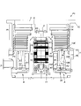
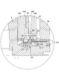
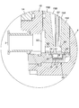
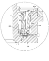
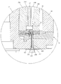
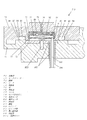
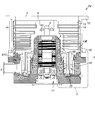
図1は、本発明の第1実施形態である真空ポンプ(ネジ溝ポンプ並行流タイプ)の断面図、図2は図1のA部拡大図、図3は図1のB部拡大図である。
1 is a cross-sectional view of a vacuum pump (thread groove pump parallel flow type) according to a first embodiment of the present invention, FIG. 2 is an enlarged view of a portion A in FIG. 1, and FIG. 3 is an enlarged view of a portion B in FIG. .
図1の真空ポンプP1は、例えば、半導体製造装置、フラット・パネル・ディスプレイ製造装置、ソーラー・パネル製造装置におけるプロセスチャンバやその他の密閉チャンバのガス排気手段等として利用される。この真空ポンプP1は、外装ケース1内に、回転翼13と固定翼14により気体を排気する翼排気部Ptと、ネジ溝19A、19Bを利用して気体を排気するネジ溝排気部Psと、これらの駆動系とを有している。
1 is used, for example, as a gas exhaust means for a process chamber or other sealed chamber in a semiconductor manufacturing apparatus, a flat panel display manufacturing apparatus, or a solar panel manufacturing apparatus. The vacuum pump P1 includes, in the outer case 1, a blade exhaust part Pt that exhausts gas by the rotary blade 13 and the fixed blade 14, and a screw groove exhaust part Ps that exhausts gas using the screw grooves 19A and 19B. These drive systems are included.
外装ケース1は、筒状のポンプケース1Aとベーススペーサ1Bとをその筒軸方向に締結ボルトで一体に連結した円筒形になっている。ポンプケース1Aの上端部側はガス吸気口2として開口しており、ベーススペーサ1Bの下端部側面にはガス排気口3を設けてある。
The outer case 1 has a cylindrical shape in which a cylindrical pump case 1A and a base spacer 1B are integrally connected with a fastening bolt in the cylinder axis direction. The upper end portion side of the pump case 1A is opened as a gas intake port 2, and a gas exhaust port 3 is provided on the side surface of the lower end portion of the base spacer 1B.
ガス吸気口2は、ポンプケース1A上縁のフランジ1Cに設けた図示しない締結ボルトにより、例えば半導体製造装置のプロセスチャンバ等、高真空となる図示しない密閉チャンバに接続される。ガス排気口3は、図示しない補助ポンプに連通接続される。
The gas inlet 2 is connected to a sealed chamber (not shown), which is a high vacuum, such as a process chamber of a semiconductor manufacturing apparatus, by a fastening bolt (not shown) provided on the flange 1C on the upper edge of the pump case 1A. The gas exhaust port 3 is connected in communication with an auxiliary pump (not shown).
ポンプケース1A内の中央部には各種電装品を内蔵する円筒状のステータベース4が設けられている。このステータベース4はベーススペーサ1Bの内底に一体に立設しているが、これとは別の実施形態として、例えば、そのステータベース4をベーススペーサ1Bとは別部品として形成してベーススペーサ1Bの内底にネジ止め固定してもよい。
A cylindrical stator base 4 containing various electrical components is provided in the center of the pump case 1A. The stator base 4 is erected integrally with the inner bottom of the base spacer 1B. As another embodiment, for example, the stator base 4 is formed as a separate component from the base spacer 1B. You may fix with screws to the inner bottom of 1B.
ステータベース4の内側には回転軸5が設けられており、回転軸5は、その上端部がガス吸気口2の方向を向き、その下端部がベーススペーサ1Bの方向を向くように配置してある。また、回転軸5の上端部はステータベース4の円筒上端面から上方に突出するように設けてある。
A rotation shaft 5 is provided inside the stator base 4, and the rotation shaft 5 is arranged so that its upper end portion faces the gas inlet 2 and its lower end portion faces the base spacer 1B. is there. Further, the upper end portion of the rotating shaft 5 is provided so as to protrude upward from the cylindrical upper end surface of the stator base 4.
また、前記回転軸5は、支持手段としての2組のラジアル磁気軸受10、10と1組のアキシャル磁気軸受11により径方向と軸方向が回転可能に支持され、この状態で、駆動手段としての駆動モータ12により回転駆動されるように構成してある。支持手段(ラジアル磁気軸受10、10、アキシャル磁気軸受11)と駆動手段(駆動モータ12)はステータベース4に収容してある。なお、ラジアル磁気軸受10、10、アキシャル磁気軸受11及び駆動モータ12は公知であるため、その具体的な詳細説明は省略する。
The rotating shaft 5 is supported by two sets of radial magnetic bearings 10 and 10 as supporting means and a set of axial magnetic bearings 11 so as to be rotatable in the radial direction and the axial direction. The drive motor 12 is configured to be rotationally driven. Support means (radial magnetic bearings 10 and 10, axial magnetic bearing 11) and drive means (drive motor 12) are accommodated in the stator base 4. In addition, since the radial magnetic bearings 10 and 10, the axial magnetic bearing 11 and the drive motor 12 are well-known, the detailed description is abbreviate | omitted.
ステータベース4の外側にはロータ6が設けられている。このロータ6は、ポンプケース1A及びベーススペーサ1Bに内包され、ステータベース4の外周を囲む円筒形状であって、その略中間に位置する環状板体の連結部60で、直径の異なる2つの筒体(第1の筒体61と第2の筒体62)をその筒軸方向に連結した形状になっている。
A rotor 6 is provided outside the stator base 4. The rotor 6 is enclosed in the pump case 1A and the base spacer 1B and has a cylindrical shape surrounding the outer periphery of the stator base 4, and is an annular plate connecting portion 60 positioned approximately in the middle between the two cylinders having different diameters. The body (the first cylinder 61 and the second cylinder 62) is connected in the cylinder axis direction.
第1の筒体61の上端には、その上端面を構成する部材として、端部材63が一体に設けられており、この端部材63を介して、前記ロータ6は前記回転軸5に固定され、回転軸5を介して、ラジアル磁気軸受10、10及びアキシャル磁気軸受11で、その軸心(回転軸5)周りに回転可能に支持されている。
An end member 63 is integrally provided at the upper end of the first cylinder 61 as a member constituting the upper end surface thereof, and the rotor 6 is fixed to the rotating shaft 5 via the end member 63. These are supported by the radial magnetic bearings 10 and 10 and the axial magnetic bearing 11 via the rotating shaft 5 so as to be rotatable around the axis (the rotating shaft 5).
図1の真空ポンプP1におけるロータ6は一つのアルミ合金塊から切り出し加工したものであることより、ロータ6を構成する第1の筒体61、第2の筒体62、連結部60、及び端部材63は一部品として形成されているが、これとは別の実施例として、連結部60を境にして第1の筒体61と第2の筒体62とが別部品で構成されるロータを採用することも可能である。この場合、第1の筒体61はアルミニウム合金等の金属材料で形成し、第2の筒体62は樹脂で形成する等、第1の筒体61と第2の筒体62の構成材料を異なるものとしてもよい。
Since the rotor 6 in the vacuum pump P1 of FIG. 1 is cut out from one aluminum alloy lump, the first cylinder 61, the second cylinder 62, the connecting portion 60, and the end constituting the rotor 6 are used. The member 63 is formed as one part. However, as an embodiment different from this, the first cylindrical body 61 and the second cylindrical body 62 are separated from each other with the connecting portion 60 as a boundary. It is also possible to adopt. In this case, the first cylindrical body 61 is formed of a metal material such as an aluminum alloy, and the second cylindrical body 62 is formed of a resin. The constituent materials of the first cylindrical body 61 and the second cylindrical body 62 are the same. It may be different.
《翼排気部Ptの詳細構成》
図1の真空ポンプP1では、ロータ6の略中間(具体的には、連結部60)より上流(ロータ6の略中間からロータ6のガス吸気口2側端部までの範囲)が翼排気部Ptとして機能する。以下、この翼排気部Ptを詳細に説明する。
<< Detailed Configuration of Blade Exhaust Pt >>
In the vacuum pump P1 of FIG. 1, the blade exhaust part is located upstream from the substantially middle part of the rotor 6 (specifically, the connecting part 60) (the range from the substantially middle part of the rotor 6 to the gas inlet 2 side end of the rotor 6). Functions as Pt. Hereinafter, the blade exhaust part Pt will be described in detail.
ロータ6の略中間より上流側のロータ6外周面、具体的には該ロータ6を構成する第1の筒体61の外周面には、複数の回転翼13が一体に設けられている。これら複数の回転翼13は、ロータ6の回転中心軸(回転軸5)若しくは外装ケース1の軸心(以下「真空ポンプ軸心」という)を中心として放射状に並んで配置されている。
A plurality of rotor blades 13 are integrally provided on the outer peripheral surface of the rotor 6 on the upstream side from the substantially middle of the rotor 6, specifically, on the outer peripheral surface of the first cylindrical body 61 constituting the rotor 6. The plurality of rotor blades 13 are arranged in a radial pattern around the rotation center axis (rotation axis 5) of the rotor 6 or the axis of the outer case 1 (hereinafter referred to as “vacuum pump axis”).
一方、ポンプケース1Aの内周側には複数の固定翼14が設けられており、これら複数の固定翼14もまた、真空ポンプ軸心を中心として放射状に並んで配置されている。
On the other hand, a plurality of fixed blades 14 are provided on the inner peripheral side of the pump case 1A, and the plurality of fixed blades 14 are also arranged in a radial pattern around the vacuum pump axis.
そして、図1の真空ポンプP1では、前記のように放射状に配置された回転翼13と固定翼14とが真空ポンプ軸心に沿って交互に多段に配置されることによって、真空ポンプP1の翼排気部Ptが構成されている。
In the vacuum pump P1 of FIG. 1, the blades of the vacuum pump P1 are arranged by arranging the rotary blades 13 and the fixed blades 14 arranged radially as described above alternately along the vacuum pump axis. An exhaust part Pt is configured.
なお、前記いずれの回転翼13も、ロータ6の外径加工部と一体的に切削加工で切り出し形成したブレード状の切削加工品であって、気体分子の排気に最適な角度で傾斜している。前記いずれの固定翼14もまた、気体分子の排気に最適な角度で傾斜している。
Each of the rotor blades 13 is a blade-like cut product that is cut and formed integrally with the outer diameter machining portion of the rotor 6 and is inclined at an angle that is optimal for exhausting gas molecules. . Any of the fixed blades 14 is also inclined at an angle optimum for exhausting gas molecules.
《翼排気部Ptによる排気動作説明》
以上の構成からなる翼排気部Ptでは、駆動モータ12の起動により、回転軸5、ロータ6および複数の回転翼13が一体に高速回転し、最上段の回転翼13がガス吸気口2から入射した気体分子に下向き方向の運動量を付与する。この下向き方向の運動量を有する気体分子が固定翼14によって次段の回転翼13側へ送り込まれる。以上のような気体分子への運動量の付与と送り込み動作とが繰り返し多段に行われることにより、ガス吸気口2側の気体分子はロータ6の下流に向かって順次移行するように排気される。
<< Exhaust operation explanation by blade exhaust part Pt >>
In the blade exhaust part Pt configured as described above, when the drive motor 12 is started, the rotating shaft 5, the rotor 6, and the plurality of rotor blades 13 integrally rotate at a high speed, and the uppermost rotor blade 13 enters from the gas inlet 2. A downward momentum is given to the gas molecules. The gas molecules having the downward momentum are sent to the rotor blade 13 at the next stage by the fixed blade 14. By applying the momentum to the gas molecules as described above and performing the feeding operation repeatedly in multiple stages, the gas molecules on the gas inlet 2 side are exhausted so as to sequentially move toward the downstream of the rotor 6.
《ネジ溝排気部Psの詳細構成》
図1の真空ポンプP1では、ロータ6の略中間(具体的には、連結部60)より下流(ロータ6の略中間からロータ6のガス排気口3側端部までの範囲)がネジ溝排気部Psとして機能する。以下、このネジ溝排気部Psを詳細に説明する。
<< Detailed Configuration of Screw Groove Exhaust Ps >>
In the vacuum pump P1 of FIG. 1, the thread groove exhaust is in the middle of the rotor 6 (specifically, the connection portion 60) downstream (the range from the substantially middle of the rotor 6 to the gas exhaust port 3 side end of the rotor 6). It functions as a part Ps. Hereinafter, the thread groove exhaust portion Ps will be described in detail.
ロータ6の略中間より下流側のロータ6、具体的には該ロータ6を構成する第2の筒体62は、ネジ溝排気部Psの回転部材として回転する部分であって、ネジ溝排気部Psの内外2重円筒形のネジ溝排気部ステータ18A、18B間に所定のギャップを介して挿入・収容される構成になっている。
The rotor 6 on the downstream side from the substantially middle of the rotor 6, specifically, the second cylindrical body 62 constituting the rotor 6 is a portion that rotates as a rotating member of the thread groove exhaust portion Ps, and is a thread groove exhaust portion. The Ps inner and outer double cylindrical thread groove exhaust part stators 18A, 18B are configured to be inserted and accommodated via a predetermined gap.
内外2重円筒形のネジ溝排気部ステータ18A、18Bのうち、内側のネジ溝排気部ステータ18Aは、その外周面が第2の筒体62の内周面と対向するように配置された円筒形の固定部材であって、第2の筒体62の内周によって囲まれるように配置されている。
Among the inner and outer double-cylindrical thread groove exhaust portion stators 18A and 18B, the inner thread groove exhaust portion stator 18A is a cylinder disposed so that the outer peripheral surface thereof faces the inner peripheral surface of the second cylindrical body 62. It is a fixed member having a shape, and is disposed so as to be surrounded by the inner periphery of the second cylindrical body 62.
一方、外側のネジ溝排気部ステータ18Bは、その内周面が第2の筒体62の外周面に対向するように配置された円筒形の固定部材であって、第2の筒体62の外周を囲むように配置されている。
On the other hand, the outer thread groove exhaust part stator 18 </ b> B is a cylindrical fixing member arranged so that its inner peripheral surface faces the outer peripheral surface of the second cylindrical body 62, and It arrange | positions so that an outer periphery may be enclosed.
内側のネジ溝排気部ステータ18Aの外周部には、ロータ6の内周側(具体的には第2の筒体62の内周側)にネジ溝排気通路R1を形成する手段として、深さが下方に向けて小径化したテーパコーン形状に変化するネジ溝19Aを形成してある。ネジ溝19Aはネジ溝排気部ステータ18Aの上端から下端にかけて螺旋状に刻設してあり、このようなネジ溝19Aを備えたネジ溝排気部ステータ18Aにより、第2の筒体62の内周側にはネジ溝排気流路(以下「内側ネジ溝排気流路R1」という)が形成される。尚、この内側のネジ溝排気部ステータ18Aはその下端が図2のように、加熱板23で支持されている。
At the outer periphery of the inner thread groove exhaust portion stator 18A, there is a depth as means for forming the thread groove exhaust passage R1 on the inner peripheral side of the rotor 6 (specifically, the inner peripheral side of the second cylindrical body 62). Is formed with a thread groove 19A that changes into a tapered cone shape with a diameter decreasing downward. The screw groove 19A is spirally engraved from the upper end to the lower end of the screw groove exhaust portion stator 18A. The screw groove exhaust portion stator 18A having such a screw groove 19A allows the inner periphery of the second cylindrical body 62 to be formed. On the side, a thread groove exhaust passage (hereinafter referred to as “inner thread groove exhaust passage R1”) is formed. The lower end of the inner thread groove exhaust portion stator 18A is supported by a heating plate 23 as shown in FIG.
外側のネジ溝排気部ステータ18Bの内周部には、ロータ6の外周側(具体的には第2の筒体62の外周側)にネジ溝排気通路R2を形成する手段として、前記ネジ溝19Aと同様のネジ溝19Bを形成してある。このようなネジ溝19Bを備えたネジ溝排気部ステータ18Bにより、第2の筒体62の外周側にはネジ溝排気流路(以下「外側ネジ溝排気流路R2」という)が形成される。なお、この外側のネジ溝排気部ステータ18Bもその下端部が図2のように、加熱板23で支持されている。
As the means for forming the screw groove exhaust passage R2 on the outer peripheral side of the rotor 6 (specifically, the outer peripheral side of the second cylindrical body 62), the screw groove exhaust passage R2 is formed on the inner peripheral portion of the outer screw groove exhaust portion stator 18B. A screw groove 19B similar to 19A is formed. A thread groove exhaust passage (hereinafter referred to as “outer thread groove exhaust passage R2”) is formed on the outer peripheral side of the second cylindrical body 62 by the thread groove exhaust portion stator 18B having such a thread groove 19B. . Note that the lower end portion of the outer thread groove exhaust portion stator 18B is also supported by the heating plate 23 as shown in FIG.
図示は省略するが、先に説明したネジ溝19A、19Bを第2の筒体62の内周面又は外周面若しくはその両面に形成することで、前記のような内側ネジ溝排気流路R1又は外側ネジ溝排気流路R2が設けられるように構成してもよい。
Although illustration is omitted, the above-described inner thread groove exhaust flow path R1 or the like described above is formed by forming the thread grooves 19A and 19B described above on the inner peripheral surface or the outer peripheral surface of the second cylindrical body 62 or on both surfaces thereof. You may comprise so that the outer side thread groove exhaust flow path R2 may be provided.
ネジ溝排気部Psでは、ネジ溝19Aと第2の筒体62の内周面でのドラッグ効果やネジ溝19Bと第2の筒体62の外周面でのドラック効果により、気体を圧縮しながら移送するため、ネジ溝19Aの深さは、内側ネジ溝排気流路R1の上流入口側(ガス吸気口2に近い方の流路開口端)で最も深く、その下流出口側(ガス排気口3に近い方の流路開口端)で最も浅くなるように設定してある。このことはネジ溝19Bも同様である。
In the screw groove exhaust portion Ps, the gas is compressed by the drag effect on the inner peripheral surface of the screw groove 19A and the second cylindrical body 62 and the drag effect on the outer peripheral surface of the screw groove 19B and the second cylindrical body 62. In order to transfer, the depth of the thread groove 19A is deepest on the upstream inlet side of the inner thread groove exhaust flow path R1 (flow path opening end closer to the gas intake port 2) and on the downstream outlet side (gas exhaust port 3). It is set so as to be shallowest at the opening end of the flow path closer to. The same applies to the thread groove 19B.
外側ネジ溝排気流路R2の上流入口は、多段に配置されている回転翼13のうち最下段の回転翼13Eと後述する連通開口部Hの上流端との間の隙間(以下「最終隙間G1」という)に連通している。また、同流路R2の下流出口は、図3のように、環状合流路S1と横穴流路S2と環状合流路S3を通じて、ガス排気口3側に連通している。
The upstream inlet of the outer thread groove exhaust flow path R2 is a gap between the lowermost rotor blade 13E among the rotor blades 13 arranged in multiple stages and the upstream end of a communication opening H described later (hereinafter referred to as “final gap G1”). "). Further, as shown in FIG. 3, the downstream outlet of the channel R2 communicates with the gas exhaust port 3 through the annular joint channel S1, the lateral hole channel S2, and the annular joint channel S3.
内側ネジ溝排気流路R1の上流入口は、ロータ6の略中間でロータ6の内周面(具体的には、連結部60の内面)に向って開口している。また、同流路R1の下流出口は、環状合流路S1と横穴流路S2と環状合流路S3を通じて、ガス排気口3側に連通している。
The upstream inlet of the inner thread groove exhaust flow path R1 is open substantially toward the inner peripheral surface of the rotor 6 (specifically, the inner surface of the connecting portion 60) in the middle of the rotor 6. Further, the downstream outlet of the channel R1 communicates with the gas exhaust port 3 through the annular joint channel S1, the lateral hole channel S2, and the annular joint channel S3.
環状合流路S1は、第2の筒体62の端部と後述の加熱部20との間に所定の隙間(図1の真空ポンプP1では、ステータベース4の下部外周を一周する形態の隙間)を設けることによって、内側及び外側ネジ溝排気流路R1、R2の下流出口と横穴流路S2とに連通するように形成してあり、また、横穴流路S2は、外側ネジ溝排気部ステータ18Bの端部に複数の切欠きを設けることによって、環状合流路S1と環状合流路S3とガス排気口3とに連通するように形成してある。
The annular joint channel S1 has a predetermined gap between the end portion of the second cylindrical body 62 and a heating unit 20 described later (in the vacuum pump P1 of FIG. 1, a gap having a form that goes around the lower outer periphery of the stator base 4). Are provided so as to communicate with the downstream outlets of the inner and outer thread groove exhaust passages R1, R2 and the lateral hole passage S2, and the lateral hole passage S2 is formed on the outer thread groove exhaust portion stator 18B. By providing a plurality of cutouts at the end of this, it is formed so as to communicate with the annular joint channel S1, the annular joint channel S3, and the gas exhaust port 3.
ロータ6の略中間には連通開口部Hが開設されており、連通開口部Hは、ロータ6の表裏面間を貫通するように形成されることで、ロータ6の外周側に存在する気体の一部を内側ネジ溝排気流路R1へ導くように機能する。かかる機能を備えた連通開口部Hは、例えば、図1のように連結部60の内外面を貫通するように形成してもよい。また、図1の真空ポンプP1では、前記連通開口部Hを複数設け、これら複数の連通開口部Hが真空ポンプ軸心に対して点対称となるように配置してある。
A communication opening H is formed substantially in the middle of the rotor 6, and the communication opening H is formed so as to penetrate between the front and back surfaces of the rotor 6. It functions to guide a part to the inner thread groove exhaust passage R1. The communication opening H having such a function may be formed so as to penetrate the inner and outer surfaces of the connecting portion 60 as shown in FIG. Further, in the vacuum pump P1 of FIG. 1, a plurality of the communication openings H are provided, and the plurality of communication openings H are arranged so as to be point-symmetric with respect to the vacuum pump axis.
《ネジ溝排気部Psにおける排気動作説明》
先に説明した翼排気部Ptの排気動作による移送で外側ネジ溝排気流路R2の上流入口や最終隙間G1に到達した気体分子は、外側ネジ溝排気流路R2や連通開口部Hから内側ネジ溝排気流路R1に移行する。この移行した気体分子は、ロータ6の回転によって生じる効果、すなわち第2の筒体62の外周面とネジ溝19Bでのドラッグ効果や、第2の筒体62の内周面とネジ溝19Aでのドラッグ効果によって、遷移流から粘性流に圧縮されながら環状合流路S1に向かって移行する。そして、環状合流路S1に到達した気体分子の粘性流は、横穴流路S2を通って環状合流路S3へ、そしてガス排気口3に流入し、ガス排気口3から図示しない補助ポンプを通じて外部へ排気される。
<< Exhaust operation explanation in screw groove exhaust part Ps >>
The gas molecules that have reached the upstream inlet of the outer thread groove exhaust flow path R2 and the final gap G1 by the transfer by the exhaust operation of the blade exhaust section Pt described above are transferred from the outer thread groove exhaust flow path R2 and the communication opening H to the inner screw. Transition to the groove exhaust passage R1. The migrated gas molecules are produced by the rotation of the rotor 6, that is, the drag effect on the outer peripheral surface of the second cylinder 62 and the screw groove 19B, or the inner peripheral surface of the second cylinder 62 and the screw groove 19A. Due to the drag effect, the transition flow moves toward the annular combined flow path S1 while being compressed into a viscous flow. The viscous flow of the gas molecules that has reached the annular joint channel S1 flows into the annular joint channel S3 through the side hole channel S2 and into the gas exhaust port 3, and then flows to the outside from the gas exhaust port 3 through an auxiliary pump (not shown). Exhausted.
《図1の真空ポンプにおける加熱部の説明》
図1の真空ポンプP1において、ネジ溝排気部ステータ18A、18Bの下部には、生成物の付着を防止する手段として、加熱部20を設けている。具体的には、ネジ溝排気部ステータ18A、18Bとその下部に配置されている前記ステータベース4との間に、この加熱部20は設けられている。
<< Description of Heating Unit in Vacuum Pump of FIG. 1 >>
In the vacuum pump P1 of FIG. 1, a heating unit 20 is provided below the thread groove exhaust unit stators 18A and 18B as a means for preventing product adhesion. Specifically, the heating section 20 is provided between the thread groove exhaust section stators 18A and 18B and the stator base 4 disposed below the thread groove exhaust section stators 18A and 18B.
前記加熱部20は、図2に示したように、凹部21を有するヒータスペーサ22と、凹部21内に配置されたヨーク25と、ヨーク25上に配置したコイル26と、ネジ溝排気部ステータ18A、18Bに当接し、凹部21を塞ぐようにヒータスペーサ22に取り付けられた加熱板23と、凹部21内を外気圧に設定可能とするシール手段24と、を備えている。
As shown in FIG. 2, the heating unit 20 includes a heater spacer 22 having a recess 21, a yoke 25 disposed in the recess 21, a coil 26 disposed on the yoke 25, and a thread groove exhaust unit stator 18A. , 18B, and a heating plate 23 attached to the heater spacer 22 so as to close the concave portion 21, and a sealing means 24 that allows the inside of the concave portion 21 to be set to an external pressure.
そして、前記コイル26に高周波の交流電流を流すことによる電磁誘導加熱により、前記加熱部20は、ヨーク25及び加熱板23を加熱し、これにより前記ヒータスペーサ22、ネジ溝排気部ステータ18A、18B、ベーススペーサ1B及びステータベース4を加熱するように構成してある。
The heating unit 20 heats the yoke 25 and the heating plate 23 by electromagnetic induction heating by passing a high-frequency alternating current through the coil 26, whereby the heater spacer 22, the thread groove exhaust unit stators 18A, 18B. The base spacer 1B and the stator base 4 are heated.
ヒータスペーサ22は、その外側面にコネクタ100を装着するためのコネクタ装着部101と、前記凹部21からコネクタ装着部101に連通する配線通し孔102と、配線通し孔102に通されてコイル26とコネクタ100とを接続するコイル26の配線103と、を備えている。前記ヨーク25にも、前記コイル26の配線103や後述する温度センサ51の配線を通すため、配線通し孔102を設けている。
The heater spacer 22 has a connector mounting portion 101 for mounting the connector 100 on its outer surface, a wiring through hole 102 communicating with the connector mounting portion 101 from the recess 21, and a coil 26 through the wiring through hole 102. And a wiring 103 of a coil 26 for connecting to the connector 100. The yoke 25 is also provided with a wiring hole 102 for passing the wiring 103 of the coil 26 and the wiring of a temperature sensor 51 described later.
また、この図2に示すコネクタ100、コネクタ装着部101、配線通し孔102、配線103、及び温度センサ51の配線は水平位置(ベーススペーサ1Bの外周に向ける方向)に配置しているが、図14に示したように垂直位置(ステータベース4の底面に向ける方向)に配置してもよい。
Further, the connector 100, the connector mounting portion 101, the wiring through hole 102, the wiring 103, and the temperature sensor 51 shown in FIG. 2 are arranged in a horizontal position (direction toward the outer periphery of the base spacer 1B). As shown in FIG. 14, it may be arranged in a vertical position (a direction toward the bottom surface of the stator base 4).
前記シール手段24は、Oリングその他のシール部材で凹部21の開口周縁をシールすることにより、内側及び外側ネジ溝排気流路R1、R2等のように真空となる領域から凹部21内を切り離し、凹部21内だけを外気圧に設定可能としている。
The sealing means 24 seals the periphery of the opening of the recess 21 with an O-ring or other sealing member, so that the interior of the recess 21 is separated from the vacuum area such as the inner and outer screw groove exhaust passages R1, R2, etc. Only the inside of the recess 21 can be set to the external pressure.
前記凹部21内は、配線通し孔102を介してヒータスペーサ22外部の大気が取り込まれることにより、大気圧となるように設定してある。なお、凹部21内には大気以外の外気を取り込むことも可能である。また、凹部21内の圧力は、大気圧に限定されることはなく、真空放電によるコイル26の絶縁被覆破壊が生じない圧力であればよい。
The inside of the recess 21 is set to be at atmospheric pressure when the atmosphere outside the heater spacer 22 is taken in via the wiring through hole 102. It should be noted that outside air other than the atmosphere can be taken into the recess 21. The pressure in the recess 21 is not limited to atmospheric pressure, and may be any pressure that does not cause the insulation coating of the coil 26 to be broken by vacuum discharge.
ヨーク25とコイル26との間は、その間に介在する絶縁板27により電気的に絶縁されている。また、ヒータスペーサ22はアルミニウム合金で形成され、加熱板23とヨーク25は、鉄系材料(例えば、純鉄、S15C、S25C)や磁性を有するステンレス材料(例えば、フェライト系ステンレス材料、SUS430、SUS304、SUS420J2)等の磁性材料で形成され、前記コイル26は、良導体(例えば、銅材料)で形成されている。
The yoke 25 and the coil 26 are electrically insulated by an insulating plate 27 interposed therebetween. The heater spacer 22 is formed of an aluminum alloy, and the heating plate 23 and the yoke 25 are made of an iron-based material (for example, pure iron, S15C, S25C) or a magnetic stainless steel material (for example, a ferritic stainless material, SUS430, SUS304). , SUS420J2) and the like, and the coil 26 is formed of a good conductor (for example, copper material).
前記コイル26に高周波の交流電流を流すと、コイル26と加熱板23及びヨーク25とが電磁結合し、加熱板23及びヨーク25の内部に渦電流が発生する。そうすると、加熱板23やヨーク25には固有の電気抵抗があるため、加熱板23やヨーク25でジュール熱が発生する。また、加熱板23やヨーク25では鉄損発熱、コイル26では銅損発熱が生じ、これらの熱によって、ネジ溝排気部ステータ18A、18Bとヒータスペーサ22が優先的に加熱される。更に、ヒータスペーサ22からの伝熱によって、ベーススペーサ1Bやステータベース4も加熱される。
When a high-frequency alternating current is passed through the coil 26, the coil 26, the heating plate 23, and the yoke 25 are electromagnetically coupled, and an eddy current is generated inside the heating plate 23 and the yoke 25. Then, since the heating plate 23 and the yoke 25 have inherent electric resistance, Joule heat is generated in the heating plate 23 and the yoke 25. Further, iron loss heat generation occurs in the heating plate 23 and the yoke 25, and copper loss heat generation occurs in the coil 26, and the thread groove exhaust portion stators 18A and 18B and the heater spacer 22 are preferentially heated by these heats. Furthermore, the base spacer 1 </ b> B and the stator base 4 are also heated by the heat transfer from the heater spacer 22.
コイル26から加熱板23までの距離と、絶縁板27の厚みに相当するコイル26からヨーク25までの距離は、必要に応じて適宜変更することができるが、ネジ溝排気部ステータ側での生成物の付着を防止する観点からは、その距離はヨーク25よりも加熱板23の方が有効に加熱できる距離に設定することが好ましい。
The distance from the coil 26 to the heating plate 23 and the distance from the coil 26 to the yoke 25 corresponding to the thickness of the insulating plate 27 can be appropriately changed as necessary, but are generated on the screw groove exhaust portion stator side. From the viewpoint of preventing adhesion of an object, the distance is preferably set to a distance at which the heating plate 23 can be heated more effectively than the yoke 25.
また、前記加熱部20では、ヨーク25の断面形状をネジ溝排気部ステータ18A、18Bの端部に向かって上向きの溝形状とし、そのヨーク25の上端部を加熱板23に近づけて配置している。これにより、ヨーク25内のコイル26は磁性材料の加熱板23とヨーク25で囲まれた空間内に配置されるから、コイル26の磁束漏れが少なくなり、加熱効率の向上が図られている。
In the heating unit 20, the cross-sectional shape of the yoke 25 is an upward groove shape toward the ends of the thread groove exhaust portion stators 18 </ b> A and 18 </ b> B, and the upper end of the yoke 25 is disposed close to the heating plate 23. Yes. Thereby, the coil 26 in the yoke 25 is disposed in a space surrounded by the heating plate 23 and the yoke 25 made of a magnetic material, so that the magnetic flux leakage of the coil 26 is reduced, and the heating efficiency is improved.
さらに、前記加熱部20は、加熱板23に取り付けた温度センサ51と、温度センサ51での検出値に基づいて加熱板23が所定の温度となるように制御する温度制御手段(図示省略)と、を備えている。
Furthermore, the heating unit 20 includes a temperature sensor 51 attached to the heating plate 23, and temperature control means (not shown) for controlling the heating plate 23 to have a predetermined temperature based on the detection value of the temperature sensor 51. It is equipped with.
さらに、前記加熱部20は、コイル26に取り付けた温度センサ(図示省略)と、温度センサでの検出値に基づいてコイル26が所定の温度を超えないように制御する保護制御手段(図示省略)と、を備えてもよい。
Further, the heating unit 20 includes a temperature sensor (not shown) attached to the coil 26, and protection control means (not shown) for controlling the coil 26 so as not to exceed a predetermined temperature based on a detection value of the temperature sensor. And may be provided.
加熱板23への温度センサ51の取付け方式としては、図2のように、凹部21側のみに開口したセンサ取付け穴50を加熱板23に形成し、このセンサ取付け穴50に温度センサ51を挿入して接着材等で固定する方式を採用することができる。温度センサ51の配線は、センサ取付け穴50から凹部21と配線通し孔102を通してコネクタ100に接続してある。
As a method of attaching the temperature sensor 51 to the heating plate 23, as shown in FIG. 2, a sensor attachment hole 50 opened only on the concave portion 21 side is formed in the heating plate 23, and the temperature sensor 51 is inserted into the sensor attachment hole 50. Then, a method of fixing with an adhesive or the like can be adopted. The wiring of the temperature sensor 51 is connected to the connector 100 from the sensor mounting hole 50 through the recess 21 and the wiring through hole 102.
図1の真空ポンプP1では、前記加熱部20がベーススペーサ1B及びステータベース4よりもネジ溝排気部ステータ18A、18Bを優先的に加熱できるようにする手段として、外側のネジ溝排気部ステータ18Bとベーススペーサ1Bとの間に隙間を空けること又は熱伝導率がより低いOリングからなる中間部材Mを介在させることで、外側のネジ溝排気部ステータ18Bとベーススペーサ1B又はステータベース4とが直接的に接触しないように構成している。なお、Oリング以外の部材を前記中間部材Mとして採用することもできる。
In the vacuum pump P1 of FIG. 1, as a means for enabling the heating unit 20 to preferentially heat the thread groove exhaust part stators 18A and 18B over the base spacer 1B and the stator base 4, an outer thread groove exhaust part stator 18B. And an intermediate member M made of an O-ring having a lower thermal conductivity is interposed between the outer space and the base spacer 1B, so that the outer thread groove exhaust portion stator 18B and the base spacer 1B or the stator base 4 are connected to each other. It is configured not to contact directly. A member other than the O-ring can be used as the intermediate member M.
図4は、加熱部の取付け構造例の説明図である。
FIG. 4 is an explanatory diagram of an example of a heating unit mounting structure.
図1の真空ポンプP1において、加熱部20は、この図4の取付け構造例のように、締結ボルトBT1でネジ溝排気部ステータ18A、18Bの端部に取り付け固定することができる。
In the vacuum pump P1 of FIG. 1, the heating unit 20 can be fixedly attached to the ends of the thread groove exhaust part stators 18A and 18B with the fastening bolts BT1, as in the example of the mounting structure of FIG.
特に、この図4の取付け構造例では、ヒータスペーサ22と加熱板23のそれぞれにボルト通し孔を設け、これらのボルト通し孔に通された締結ボルトBT1でヒータスペーサ22と加熱板23とを一体にしてネジ溝排気部ステータ18A、18Bの端部に取り付け固定することで、加熱部20とネジ溝排気部ステータ18A、18Bからなる加熱ユニットが構成されるようにしている。
In particular, in the mounting structure example of FIG. 4, a bolt through hole is provided in each of the heater spacer 22 and the heating plate 23, and the heater spacer 22 and the heating plate 23 are integrated with a fastening bolt BT1 passed through these bolt through holes. Thus, a heating unit including the heating unit 20 and the thread groove exhaust part stators 18A and 18B is configured by being fixed to the end portions of the thread groove exhaust part stators 18A and 18B.
また、この図4の取付け構造例では、ヒータスペーサ22とベーススペーサ1Bとに共通のボルト通し孔を設け、この共通のボルト通し孔に通された締結ボルトBT2で加熱部20をベーススペーサ1Bに後付け固定している。
Further, in the mounting structure example of FIG. 4, a common bolt through hole is provided in the heater spacer 22 and the base spacer 1B, and the heating part 20 is attached to the base spacer 1B by the fastening bolt BT2 passed through the common bolt through hole. It is fixed later.
図4のように、加熱部20をベーススペーサ1Bに組み付けた後は、ネジ溝排気部ステータ18A、18Bの加熱状態を点検する作業において、特にそのネジ溝排気部ステータ18A、18B下端付近の表面温度を温度計測器で測定することが困難である。しかしながら、先に説明した加熱部20とネジ溝排気部ステータ18A、18Bからなる加熱ユニットの状態では、ネジ溝排気部ステータ18A、18Bの周りにベーススペーサ1Bが存在しないので、ネジ溝排気部ステータ18A、18B下端付近の表面温度を温度計測器で容易に測定することができる等、ネジ溝排気部ステータ18A、18Bの加熱状態を点検する際の作業性に優れる。
As shown in FIG. 4, after the heating part 20 is assembled to the base spacer 1B, in the work of checking the heating state of the thread groove exhaust part stators 18A, 18B, especially the surface near the lower ends of the thread groove exhaust part stators 18A, 18B. It is difficult to measure temperature with a temperature meter. However, in the state of the heating unit including the heating unit 20 and the thread groove exhaust part stators 18A and 18B described above, the base spacer 1B does not exist around the thread groove exhaust part stators 18A and 18B. The surface temperature in the vicinity of the lower ends of 18A and 18B can be easily measured with a temperature measuring instrument, and the workability when checking the heating state of the thread groove exhaust portion stators 18A and 18B is excellent.
また、この図4の取付け構造例では、ヒータスペーサ22よりもネジ溝排気部ステータ18A、18Bを優先的に加熱できるようにする手段として、ヒータスペーサ22と加熱板23の境界付近において、前記締結ボルトBT1のボルト通し孔を内含する円周状の溝のような肉抜き部Nを設けることにより、加熱板23とヒータスペーサ22の接触面積を減らし、加熱板23からヒータスペーサ22への伝熱を低減している。
Further, in the mounting structure example of FIG. 4, as a means for preferentially heating the thread groove exhaust portion stators 18 </ b> A and 18 </ b> B over the heater spacer 22, the fastening is performed near the boundary between the heater spacer 22 and the heating plate 23. By providing a hollow portion N such as a circumferential groove including the bolt through hole of the bolt BT1, the contact area between the heating plate 23 and the heater spacer 22 is reduced, and the transmission from the heating plate 23 to the heater spacer 22 is reduced. Reduces heat.
前記加熱部20において、凹部21とヨーク25の固定方式としては、凹部21内にヨーク25を圧入する方式、図示しないネジ止め固定する方式、あるいは、凹部21内にヨーク25を接着する方式を採用することができる。
In the heating unit 20, as a method of fixing the recess 21 and the yoke 25, a method of press-fitting the yoke 25 into the recess 21, a method of fixing with screws (not shown), or a method of bonding the yoke 25 to the recess 21 is adopted. can do.
また、前記加熱部20において、ヨーク25とコイル26の固定方式としては、ヨーク25内に樹脂等を充填することで、コイル26全体を樹脂等でモールドする方式を採用することができる。
Further, in the heating unit 20, as a method of fixing the yoke 25 and the coil 26, a method of molding the entire coil 26 with resin or the like by filling the yoke 25 with resin or the like can be employed.
さらに、前記加熱部20において、加熱板23とネジ溝排気部ステータ18A、18Bの固定方式としては、例えば図4のように加熱板23の表面に凸部を設け、この凸部を外側のネジ溝排気部ステータ18Bと内側のネジ溝排気部ステータ18Aとの間に圧入する方式、あるいは、前記凸部を外側のネジ溝排気部ステータ18Bと内側のネジ溝排気部ステータ18Aとの間に嵌め込み、それらを接着する方式を採用することができる。
Further, in the heating unit 20, as a method for fixing the heating plate 23 and the screw groove exhaust portion stators 18A and 18B, for example, a convex portion is provided on the surface of the heating plate 23 as shown in FIG. A method of press-fitting between the groove exhaust portion stator 18B and the inner screw groove exhaust portion stator 18A, or fitting the convex portion between the outer screw groove exhaust portion stator 18B and the inner screw groove exhaust portion stator 18A. The method of bonding them can be adopted.
なお、前記加熱部20において、加熱板23とネジ溝排気部ステータ18A、18Bは前記の通り締結ボルトBT1によって締結されるので、先に説明した加熱板23とネジ溝排気部ステータ18A、18Bの圧入や接着による固定方式は、必要に応じて省略することも可能である。
In the heating unit 20, since the heating plate 23 and the thread groove exhaust part stators 18A and 18B are fastened by the fastening bolt BT1 as described above, the heating plate 23 and the thread groove exhaust part stators 18A and 18B described above are connected. The fixing method by press-fitting or adhesion can be omitted if necessary.
図5は、加熱部に冷却手段を設けた構造例の説明図である。
FIG. 5 is an explanatory diagram of a structural example in which cooling means is provided in the heating unit.
図1の真空ポンプP1において冷却手段を取り付ける場合は、例えば、この図5の構造例のように、加熱部20のヒータスペーサ22を鋳造で作製する際に、そのヒータスペーサ22の中に冷却手段として水冷管7を埋め込むことができる。
When the cooling means is attached to the vacuum pump P1 of FIG. 1, for example, when the heater spacer 22 of the heating unit 20 is manufactured by casting as in the structural example of FIG. 5, the cooling means is included in the heater spacer 22. A water-cooled tube 7 can be embedded.
ヒータスペーサ22とベーススペーサ1Bは別部品であり、ヒータスペーサ22は全体として比較的薄いドーナツ形状板のような形態であることから、鋳造によるヒータスペーサ22の作製作業、及び、その鋳造の際に前記水冷管7をヒータスペーサ22に鋳込む作業自体は比較的容易なものである。
Since the heater spacer 22 and the base spacer 1B are separate parts, and the heater spacer 22 is in the form of a relatively thin donut-shaped plate as a whole, the heater spacer 22 is manufactured by casting and the casting is performed. The operation of casting the water-cooled tube 7 into the heater spacer 22 is relatively easy.
図6は、排気口での生成物の付着を加熱により防止する構造例の説明図である。
FIG. 6 is an explanatory diagram of a structure example for preventing the product from adhering to the exhaust port by heating.
この図6の構造例は、排気口3を構成する排気管30の外周に伝熱管8を装着し、その伝熱管8端部のフランジ部を締結ボルトBT3で加熱部20のヒータスペーサ22外周部に取付けたものである。この構造例では、ヒータスペーサ22の熱で伝熱管8を介して排気管30を加熱し、排気口3における生成物の付着を防止する。
In the structural example of FIG. 6, the heat transfer tube 8 is attached to the outer periphery of the exhaust pipe 30 constituting the exhaust port 3, and the flange portion at the end of the heat transfer tube 8 is connected to the outer periphery of the heater spacer 22 of the heating unit 20 with the fastening bolt BT3. It is attached to. In this structural example, the exhaust pipe 30 is heated via the heat transfer pipe 8 by the heat of the heater spacer 22 to prevent the product from adhering to the exhaust port 3.
伝熱管8を排気管30に装着する方式としては、例えば、伝熱管8をその軸方向に縦割りで複数(例えば2分割)に分割して取り付ける方式や、排気管30の直径以下に取り付ける方式を採用することができる。
As a method of attaching the heat transfer tube 8 to the exhaust pipe 30, for example, a method of attaching the heat transfer tube 8 by dividing the heat transfer tube 8 into a plurality of parts (for example, two divisions) in the axial direction, or a method of attaching the heat transfer tube 8 to a diameter equal to or less than the diameter of the exhaust pipe 30. Can be adopted.
図7は、加熱部のヒータスペーサとベーススペーサとを一体化した構造例の説明図である。
FIG. 7 is an explanatory diagram of a structural example in which the heater spacer and the base spacer of the heating unit are integrated.
先に説明した加熱部20のヒータスペーサ22は、図7の構造例のようにベーススペーサ1Bと一体化することができる。これにより、部品点数が削減でき、ベーススペーサ1Bに対するヒータスペーサ22の組み付け作業が不要となり、ポンプ組立精度の向上も図れる。
The heater spacer 22 of the heating unit 20 described above can be integrated with the base spacer 1B as in the structure example of FIG. As a result, the number of parts can be reduced, the work of assembling the heater spacer 22 to the base spacer 1B becomes unnecessary, and the pump assembly accuracy can be improved.
図8は、加熱部のヒータスペーサとベーススペーサとステータベースとを一体化した構造例の説明図である。
FIG. 8 is an explanatory diagram of a structural example in which the heater spacer, the base spacer, and the stator base of the heating unit are integrated.
先に説明した加熱部20のヒータスペーサ22とベーススペーサ1Bとステータベース4とを図8のように一体化することもでき、これにより、更なる部品点数の削減、及びポンプ組立精度の向上も図れる。
The heater spacer 22, the base spacer 1B, and the stator base 4 of the heating unit 20 described above can be integrated as shown in FIG. 8, thereby further reducing the number of parts and improving the pump assembly accuracy. I can plan.
この図8の取付け構造例では、内側のネジ溝排気部ステータ18Aと加熱板23のそれぞれにボルト通し孔を設け、これらのボルト通し孔に通された締結ボルトBT4で内側のネジ溝排気部ステータ18Aと加熱板23とを一体にしてステータベース4に取り付け固定する構成と、外側のネジ溝排気部ステータ18Bにボルト通し孔を設け、該ボルト通し孔に通された締結ボルトBT4で、外側のネジ溝排気部ステータ18Bの下側の端面が加熱板23と当接するように外側のネジ溝排気部ステータ18Bをベーススペーサ1Bに取り付け固定する構成と、を採用している。
In the mounting structure example of FIG. 8, a bolt through hole is provided in each of the inner screw groove exhaust portion stator 18A and the heating plate 23, and the inner screw groove exhaust portion stator is connected with a fastening bolt BT4 passed through these bolt through holes. 18A and the heating plate 23 are integrated and fixed to the stator base 4, and a bolt through hole is provided in the outer thread groove exhaust portion stator 18B, and a fastening bolt BT4 passed through the bolt through hole A configuration is adopted in which the outer thread groove exhaust portion stator 18B is attached and fixed to the base spacer 1B so that the lower end surface of the thread groove exhaust portion stator 18B contacts the heating plate 23.
図9は、温度センサの別の取付け例の説明図である。
FIG. 9 is an explanatory diagram of another example of attachment of the temperature sensor.
前記温度センサ51は、この図9の取付け例のようにネジ溝排気部ステータ18A、18Bに埋め込む形式で取り付けてもよい。図9の取付け例では、凹部21から加熱板23を通ってネジ溝排気部ステータ18A、18Bに達する長さのセンサ取付け穴50を形成し、このセンサ取付け穴50に温度センサ51を挿入して接着材等で固定している。この場合も、温度センサ51の配線は、センサ取付け穴50から凹部21と配線通し孔102を通してコネクタ100に接続してある。ネジ溝排気部ステータ18A、18Bの下端部と加熱板23の上端部との間にはシール手段52(例えば、Oリング)を配置してある。
The temperature sensor 51 may be attached in a manner embedded in the thread groove exhaust part stators 18A and 18B as in the attachment example of FIG. In the mounting example of FIG. 9, a sensor mounting hole 50 having a length reaching the screw groove exhaust portion stators 18 </ b> A and 18 </ b> B from the recess 21 through the heating plate 23 is formed, and the temperature sensor 51 is inserted into the sensor mounting hole 50. It is fixed with adhesive. Also in this case, the wiring of the temperature sensor 51 is connected to the connector 100 from the sensor mounting hole 50 through the recess 21 and the wiring through hole 102. Seal means 52 (for example, an O-ring) is disposed between the lower end portions of the thread groove exhaust portion stators 18A and 18B and the upper end portion of the heating plate 23.
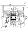
図10は、本発明の第2実施形態である真空ポンプ(ネジ溝ポンプ折り返し流タイプ)の断面図である。
FIG. 10 is a sectional view of a vacuum pump (thread groove pump return flow type) according to the second embodiment of the present invention.
図1の真空ポンプP1は、ロータ6の略下半分(第2の筒体62)の内周側と外周側を並行してガスが流れる構成(ネジ溝ポンプ並行流タイプ)であるが、この図10の真空ポンプP2は、そのタイプが異なる。
The vacuum pump P1 of FIG. 1 has a configuration in which gas flows in parallel on the inner peripheral side and the outer peripheral side of the substantially lower half (second cylindrical body 62) of the rotor 6 (thread groove pump parallel flow type). The type of vacuum pump P2 in FIG. 10 is different.
すなわち、図10の真空ポンプP2は、同図矢印Uで示したように、ロータ6を構成する第2の筒体62の下端側と上端側でガスの流れが上下方向に折り返すことにより、ロータ6の略下半分(第2の筒体62)の内周側と外周側とでガスが逆向きに流れる構成(ネジ溝ポンプ折り返し流タイプ)である。なお、その構成以外の真空ポンプP2の基本的な構成については図1の真空ポンプP1と同様であるため、図10では、図1に示した部材と同一部材に同一の符号を付し、その詳細説明は省略する。
That is, the vacuum pump P2 shown in FIG. 10 is configured so that the gas flow is turned up and down at the lower end side and the upper end side of the second cylindrical body 62 constituting the rotor 6 as shown by the arrow U in FIG. 6 is a configuration in which gas flows in the opposite direction between the inner peripheral side and the outer peripheral side of the substantially lower half (second cylindrical body 62) (screw groove pump return flow type). Since the basic configuration of the vacuum pump P2 other than that configuration is the same as that of the vacuum pump P1 of FIG. 1, in FIG. 10, the same members as those shown in FIG. Detailed description is omitted.
先に説明した図1の真空ポンプP1で採用の加熱部20は、この図10のようなネジ溝ポンプ折り返し流タイプの真空ポンプP2にも適用することができる。なお、図10の真空ポンプP2に適用された加熱部20の具体的な構成は、図1の真空ポンプP1で採用の加熱部20と同様であるため、その詳細説明は省略する。
The heating unit 20 employed in the previously described vacuum pump P1 of FIG. 1 can also be applied to a thread groove pump return flow type vacuum pump P2 as shown in FIG. The specific configuration of the heating unit 20 applied to the vacuum pump P2 in FIG. 10 is the same as that of the heating unit 20 employed in the vacuum pump P1 in FIG.
また、図10に示したガス排気口3は、図1に示したような排気口の構成をステータベース4に構成してもよい。
Further, the gas exhaust port 3 shown in FIG. 10 may have the configuration of the exhaust port as shown in FIG.
図11は、本発明の第3実施形態である真空ポンプ(ネジ溝ポンプ単流タイプ)の断面図である。
FIG. 11 is a cross-sectional view of a vacuum pump (thread groove pump single flow type) according to a third embodiment of the present invention.
この図11の真空ポンプP3は、図1の真空ポンプP1において、内側のネジ溝排気部ステータ18Aを省略することで、ロータ6の外周側のみにネジ溝排気流路R2が形成されるように構成したものである。
The vacuum pump P3 of FIG. 11 is configured such that the thread groove exhaust passage R2 is formed only on the outer peripheral side of the rotor 6 by omitting the inner thread groove exhaust portion stator 18A in the vacuum pump P1 of FIG. It is composed.
この図11のような真空ポンプP3にも、図1の真空ポンプP1で採用の加熱部20を適用することができる。特に、この図11の適用例では、加熱部20の具体的な構成として、第2の筒体62に向かって突出した突起28を加熱板23に設けている。
The heating unit 20 employed in the vacuum pump P1 in FIG. 1 can also be applied to the vacuum pump P3 in FIG. In particular, in the application example of FIG. 11, as a specific configuration of the heating unit 20, a protrusion 28 protruding toward the second cylindrical body 62 is provided on the heating plate 23.
かかる突起28は、第2の筒体62の内周と対向するように配置されることでクリアランス・シールを形成し、ネジ溝排気流路R2の下流出口から環状合流路S1に到達したガスがロータ6の内側空間へ侵入することを減少する。
The protrusions 28 are arranged so as to face the inner periphery of the second cylindrical body 62 to form a clearance seal, and the gas that has reached the annular combined flow path S1 from the downstream outlet of the thread groove exhaust flow path R2 is formed. Intrusion into the inner space of the rotor 6 is reduced.
なお、この図11の加熱部20において、前記突起6以外の具体的な構成は、図1の真空ポンプP1で採用の加熱部20と同様であるため、その詳細説明は省略する。
In the heating unit 20 of FIG. 11, the specific configuration other than the protrusion 6 is the same as that of the heating unit 20 employed in the vacuum pump P1 of FIG.
図12は、加熱部のヨークを省略した構造例の説明図である。
FIG. 12 is an explanatory diagram of a structural example in which the yoke of the heating unit is omitted.
前記加熱部20のヒータスペーサ22は、磁性材料で形成することもできる。この場合には、図12の構造例のように、ヨーク25(図1参照)を省略することができ、これにより、部品点数の削減を図れる。
The heater spacer 22 of the heating unit 20 can be formed of a magnetic material. In this case, the yoke 25 (see FIG. 1) can be omitted as in the structural example of FIG. 12, thereby reducing the number of parts.
この図12の構造例においては、前記の通り、ヒータスペーサ22が磁性材料であるため、コイル26に高周波の交流電流が流れると、コイル26と加熱板23との電磁結合だけでなく、更に、コイル26とヒータスペーサ22とが電磁結合し、加熱板23の他、ヒータスペーサ22の内部にも渦電流が生じる。これにより、ヒータスペーサ22でも十分なジュール熱が発生し、ヒータスペーサ22からの伝熱によってベーススペーサ1Bやステータベース4を加熱することができる。
In the structural example of FIG. 12, since the heater spacer 22 is a magnetic material as described above, when a high-frequency alternating current flows through the coil 26, not only the electromagnetic coupling between the coil 26 and the heating plate 23, but also The coil 26 and the heater spacer 22 are electromagnetically coupled, and an eddy current is generated not only in the heating plate 23 but also in the heater spacer 22. Accordingly, sufficient Joule heat is generated even in the heater spacer 22, and the base spacer 1 </ b> B and the stator base 4 can be heated by heat transfer from the heater spacer 22.
図13は、コイルの磁束漏れをより一層効果的に減少し得る構造例の説明図である。
FIG. 13 is an explanatory diagram of a structural example that can more effectively reduce the magnetic flux leakage of the coil.
前記加熱部20では、コイル26の配線103や温度センサ51の配線を通すため、前記の通り、ヨーク25にも配線通し孔102を形成しているので、コイル26の磁束がその配線通し孔102を通じて外部に漏れる可能性がある。
In the heating unit 20, since the wiring 103 of the coil 26 and the wiring of the temperature sensor 51 are passed, the wiring through hole 102 is also formed in the yoke 25 as described above. There is a possibility of leaking outside.
この一方、図13の構造例では、磁束漏れ低減手段として、ヨーク25からコネクタ装着部101までの配線通し孔102全範囲及びコネクタ装着部101の一部に磁性材料からなるシールドパイプ200を装着し、また、コネクタ100の周囲に磁性材料からなるシールド板201を設置しているため、前記のような磁束漏れを効果的に減少することができる。
On the other hand, in the structural example of FIG. 13, a shield pipe 200 made of a magnetic material is attached to the entire range of the wiring through hole 102 from the yoke 25 to the connector attachment portion 101 and a part of the connector attachment portion 101 as magnetic flux leakage reducing means. In addition, since the shield plate 201 made of a magnetic material is installed around the connector 100, the above-described magnetic flux leakage can be effectively reduced.
なお、図1の真空ポンプP1でも、この図13の構造例を適用することで、磁束漏れの減少を図っている。また、この図13の構造例は、図1の真空ポンプP1のように、加熱部20の凹部21内が外気圧となる構成のものだけでなく、そのような凹部21内が真空となる構成のものにも適用することができる。
Note that the vacuum pump P1 of FIG. 1 also reduces magnetic flux leakage by applying the structural example of FIG. In addition, the structure example of FIG. 13 is not limited to a configuration in which the inside of the concave portion 21 of the heating unit 20 becomes an external pressure as in the vacuum pump P1 of FIG. It can also be applied to those.
ところで、この図13の構造例では、シールドパイプ200とシールド板201を併用したが、シールドパイプ200とシールド板201のいずれか一方だけでも、十分に磁束漏れを減少可能であるなら、他方を省略することもできる。
By the way, in the structural example of FIG. 13, the shield pipe 200 and the shield plate 201 are used together. However, if only one of the shield pipe 200 and the shield plate 201 can sufficiently reduce magnetic flux leakage, the other is omitted. You can also
図14は加熱部の構造の別例の説明図、図15は図14に示した加熱部の部分拡大図である。
FIG. 14 is an explanatory view of another example of the structure of the heating unit, and FIG. 15 is a partially enlarged view of the heating unit shown in FIG.
この図14に示した加熱部70は、図1に示した本発明の第1実施形態である真空ポンプ(ネジ溝ポンプ並行流タイプ)に適用している。図1と同符号の構成の詳細説明は省略する。
The heating unit 70 shown in FIG. 14 is applied to the vacuum pump (thread groove pump parallel flow type) according to the first embodiment of the present invention shown in FIG. Detailed description of the same reference numerals as those in FIG. 1 is omitted.
図14の加熱部70は、図15に示したように、凹部72を有するヒータスペーサ71と、凹部72内に配置されたヨーク73と、図14に示したネジ溝排気部ステータ18A、18Bの下側端面に当接し、凹部72を塞ぐようにヒータスペーサ71に取り付けられた溝75を有する加熱板74と、溝75内に配置したコイル77と、凹部72及び溝75内を外気圧に設定可能とするシール手段として弾性を持つOリング83と、を備えている。
As shown in FIG. 15, the heating unit 70 in FIG. 14 includes a heater spacer 71 having a recess 72, a yoke 73 disposed in the recess 72, and the thread groove exhaust portion stators 18A and 18B shown in FIG. A heating plate 74 having a groove 75 attached to the heater spacer 71 so as to contact the lower end surface and close the concave portion 72, a coil 77 disposed in the groove 75, and the concave portion 72 and the groove 75 are set to an external pressure. An elastic O-ring 83 is provided as an enabling sealing means.
そして、コイル77に高周波の交流電流を流すことによる電磁誘導加熱により、加熱部70は、ヨーク73及び加熱板74を加熱し、これによりヒータスペーサ71、ネジ溝排気部ステータ18A、18B、ベーススペーサ1B及びステータベース4を加熱するように構成してある。
The heating unit 70 heats the yoke 73 and the heating plate 74 by electromagnetic induction heating by causing a high-frequency alternating current to flow through the coil 77, whereby the heater spacer 71, the thread groove exhaust part stators 18A and 18B, the base spacer. 1B and the stator base 4 are configured to be heated.
前記Oリング83は、図15に示した凹部72及び溝75の開口周縁をシールすることにより、図1に示した内側及び外側ネジ溝排気流路R1、R2等のように真空となる領域から凹部72及び溝75内を切り離し、凹部72及び溝75内を外気圧に設定可能としている。
The O-ring 83 seals the periphery of the opening of the recess 72 and the groove 75 shown in FIG. 15, so that the O-ring 83 can be removed from a region that is in a vacuum like the inner and outer screw groove exhaust passages R 1 and R 2 shown in FIG. The inside of the recess 72 and the groove 75 can be separated, and the inside of the recess 72 and the groove 75 can be set to the external pressure.
前記Oリング83を備える構成の場合は、図15に示したように、Oリング83を加熱板74に取り付けるOリング溝84と、Oリング溝84の開口端面から底面までの間に設けられる最小直径部85と、を有し、最小直径部85は、Oリング83の内径より大きいこと又はOリング溝84の縁に設けた突起部86で構成されることにより、Oリング83の脱落を防止するOリング脱落防止手段として機能するように構成してもよい。
In the case of the configuration including the O-ring 83, as shown in FIG. 15, the O-ring groove 84 for attaching the O-ring 83 to the heating plate 74 and the minimum provided between the opening end surface and the bottom surface of the O-ring groove 84 are provided. And the minimum diameter portion 85 is configured to be larger than the inner diameter of the O-ring 83 or the protrusion 86 provided at the edge of the O-ring groove 84 to prevent the O-ring 83 from falling off. You may comprise so that it may function as an O-ring drop-off prevention means.
さらに、図15に示したようなOリング溝84及びOリング83をヒータスペーサ71に設置してもよく、この際には前記Oリング脱落防止手段を削除してもよい。
Further, an O-ring groove 84 and an O-ring 83 as shown in FIG. 15 may be installed in the heater spacer 71. In this case, the O-ring drop prevention means may be deleted.
図15において、加熱板74とコイル77との間は、その間に介在する絶縁板81により電気的に絶縁されている。ヒータスペーサ71はアルミニウム合金で形成され、加熱板74とヨーク73は、鉄系材料(例えば、純鉄、S15C、S25C)や磁性を有するステンレス材料(例えば、フェライト系ステンレス材料、SUS430、SUS304、SUS420J2)等の磁性材料で形成され、コイル77は、良導体(例えば、銅材料)で形成されている。
In FIG. 15, the heating plate 74 and the coil 77 are electrically insulated by an insulating plate 81 interposed therebetween. The heater spacer 71 is made of an aluminum alloy, and the heating plate 74 and the yoke 73 are made of an iron-based material (for example, pure iron, S15C, S25C) or a magnetic stainless steel material (for example, a ferritic stainless material, SUS430, SUS304, SUS420J2). The coil 77 is made of a good conductor (for example, a copper material).
前記コイル77に高周波の交流電流を流すと、コイル77と加熱板74及びヨーク73とが電磁結合し、加熱板74及びヨーク73の内部に渦電流が発生する。そうすると、加熱板74やヨーク73には固有の電気抵抗があるため、加熱板74やヨーク73でジュール熱が発生する。また、加熱板74やヨーク73では鉄損発熱、コイル77では銅損発熱が生じ、これらの熱によって、ネジ溝排気部ステータ18A、18Bとヒータスペーサ71が優先的に加熱される。更に、ヒータスペーサ71からの伝熱によって、ベーススペーサ1Bやステータベース4も加熱される。
When a high-frequency alternating current is passed through the coil 77, the coil 77, the heating plate 74, and the yoke 73 are electromagnetically coupled, and an eddy current is generated inside the heating plate 74 and the yoke 73. Then, since the heating plate 74 and the yoke 73 have inherent electric resistance, Joule heat is generated in the heating plate 74 and the yoke 73. Further, iron loss heat is generated in the heating plate 74 and the yoke 73, and copper loss heat is generated in the coil 77, and the thread groove exhaust portion stators 18A and 18B and the heater spacer 71 are preferentially heated by these heats. Further, the base spacer 1 </ b> B and the stator base 4 are also heated by the heat transfer from the heater spacer 71.
コイル77からヨーク73までの距離と、絶縁板81の厚みに相当するコイル77から加熱板74までの距離は、必要に応じて適宜変更することができるが、ネジ溝排気部ステータ側での生成物の付着を防止する観点からは、その距離はヨーク73よりも加熱板74の方が有効に加熱できる距離に設定することが好ましい。
The distance from the coil 77 to the yoke 73 and the distance from the coil 77 to the heating plate 74 corresponding to the thickness of the insulating plate 81 can be appropriately changed as necessary, but are generated on the screw groove exhaust portion stator side. From the viewpoint of preventing adhesion of an object, the distance is preferably set to a distance at which the heating plate 74 can be heated more effectively than the yoke 73.
前記加熱部70では、ヨーク73の断面形状は板形状とし、そのヨーク73の上端部を加熱板74に近づけて配置している。これにより、加熱板74内のコイル77は磁性材料の加熱板74とヨーク73で囲まれた空間内に配置されるから、コイル77の磁束漏れが少なくなり、加熱効率の向上が図られている。
In the heating unit 70, the yoke 73 has a plate-like cross-sectional shape, and the upper end of the yoke 73 is disposed close to the heating plate 74. As a result, the coil 77 in the heating plate 74 is disposed in a space surrounded by the heating plate 74 of magnetic material and the yoke 73, so that the magnetic flux leakage of the coil 77 is reduced and the heating efficiency is improved. .
また、前記加熱部70は、センサ取付け穴78に取り付けた温度センサ79と、温度センサ79での検出値に基づいて加熱板74が所定の温度となるように制御する温度制御手段(図示省略)と、を備えている。
The heating unit 70 includes a temperature sensor 79 attached to the sensor attachment hole 78, and temperature control means (not shown) for controlling the heating plate 74 to have a predetermined temperature based on the detection value of the temperature sensor 79. And.
さらに、前記加熱部70は、コイル77に取り付けた温度センサ80と、温度センサ80での検出値に基づいてコイル77が所定の温度を超えないように制御する保護制御手段(図示省略)と、を備えてもよい。
Furthermore, the heating unit 70 includes a temperature sensor 80 attached to the coil 77, protection control means (not shown) for controlling the coil 77 so as not to exceed a predetermined temperature based on a detection value of the temperature sensor 80, May be provided.
前記加熱板74への温度センサ79の取付けは、図15に示したように、溝75側のみに開口したセンサ取付け穴78を加熱板74に形成し、このセンサ取付け穴78に温度センサ79を挿入している。また、コイル77への温度センサ80の取付けは、図15に示したように、コイル77の表面に温度センサ80を貼り付けてある。そして、これら2つの温度センサ79、80のうち、温度センサ79の配線は、センサ取付け穴78から溝75と凹部72と配線通し孔102を通してコネクタ100に接続し、また、温度センサ80の配線は、溝75から凹部72と配線通し孔102を通してコネクタ100に接続してある。
As shown in FIG. 15, the temperature sensor 79 is attached to the heating plate 74 by forming a sensor mounting hole 78 opened only on the groove 75 side in the heating plate 74, and attaching the temperature sensor 79 to the sensor mounting hole 78. Inserting. In addition, the temperature sensor 80 is attached to the coil 77 as shown in FIG. Of these two temperature sensors 79, 80, the wiring of the temperature sensor 79 is connected to the connector 100 from the sensor mounting hole 78 through the groove 75, the recess 72 and the wiring through hole 102, and the wiring of the temperature sensor 80 is The groove 75 is connected to the connector 100 through the recess 72 and the wiring through hole 102.
図15の加熱部70では、前記溝75及びセンサ取付け穴78内に樹脂82を充填することで、コイル77、絶縁板81、温度センサ79、80をモールドしている。また、コイル77の脱落を防止する手段として、前記溝75の縁に設けた突起部76で構成した脱落防止手段を備えてもよい。
15, the coil 77, the insulating plate 81, and the temperature sensors 79 and 80 are molded by filling the groove 75 and the sensor mounting hole 78 with the resin 82. Further, as a means for preventing the coil 77 from dropping off, a dropping prevention means constituted by a protrusion 76 provided on the edge of the groove 75 may be provided.
図15の加熱部70は、ヨーク73をヒータスペーサ71の凹部72内に締結ボルトBT5で固定した構成を採用している。これとは違う構成として、図示は省略するが、かかる加熱部70は、前記凹部72を削除したヒータスペーサ71と、ヨーク73とを備え、かつ、該ヨーク73を内包するように前記溝75を加熱板74に形成した構成と、ヒータスペーサ71の上に締結ボルトBT5でヨーク73を固定した構成と、を採用してもよい。このような構成からなる加熱部70によると、前記凹部72を省略することができ、これにより加工部の削減を図れる。なお、このような構成からなる加熱部70は、機能的には図14、15に示した構成の加熱部70と同様であるため、その詳細説明は省略する。
15 employs a configuration in which the yoke 73 is fixed in the recess 72 of the heater spacer 71 with the fastening bolt BT5. Although not shown in the drawings as a different configuration, the heating unit 70 includes a heater spacer 71 from which the concave portion 72 is removed, and a yoke 73, and the groove 75 is formed so as to contain the yoke 73. You may employ | adopt the structure formed in the heating plate 74, and the structure which fixed the yoke 73 on the heater spacer 71 with fastening bolt BT5. According to the heating unit 70 having such a configuration, the concave portion 72 can be omitted, thereby reducing the number of processed portions. The heating unit 70 having such a configuration is functionally similar to the heating unit 70 having the configuration illustrated in FIGS. 14 and 15, and thus detailed description thereof is omitted.
以上説明したように、第1から第3実施形態の真空ポンプP1、P2、P3では、加熱部20(70)の具体的な構成として、コイル26(77)に交流電流を流すことによる電磁誘導加熱でヨーク25(73)及び加熱板23(74)を加熱し、これによりヒータスペーサ22(71)、ネジ溝排気部ステータ18A、18B、ベーススペーサ1B及びステータベース4を加熱する構成を採用した。このため、加熱部20(70)によるベーススペーサ1B及びステータベース4の加熱によってベーススペーサ1B及びステータベース4内での生成物の付着も防止できることより、真空ポンプ全体としての生成物の付着量を低減することができる。
As described above, in the vacuum pumps P1, P2, and P3 of the first to third embodiments, as a specific configuration of the heating unit 20 (70), electromagnetic induction by flowing an alternating current through the coil 26 (77). Heating the yoke 25 (73) and the heating plate 23 (74) by heating, thereby adopting a configuration in which the heater spacer 22 (71), the thread groove exhaust portion stators 18A and 18B, the base spacer 1B and the stator base 4 are heated. . For this reason, since the adhesion of the product in the base spacer 1B and the stator base 4 can be prevented by heating the base spacer 1B and the stator base 4 by the heating unit 20 (70), the adhesion amount of the product as a whole vacuum pump can be reduced. Can be reduced.
また、第1から第3実施形態の真空ポンプP1、P2、P3によると、加熱部20(70)の具体的な構成として、シール手段24(83)により外気圧に設定可能なヒータスペーサ22の凹部21(加熱板74の溝75)内に、コイル26(77)が配置される構成、及び、凹部21(溝75)内を大気圧又はそれに近い圧力等、真空放電が生じない外気圧に設定する構成を採用したため、真空放電によるコイル26(77)の絶縁被覆破壊を防止し、コイル26(77)の長寿命化を図ることができる。また、コイル26(77)の絶縁被覆破壊によるショート等、真空ポンプの電気系統の故障を防止でき、真空ポンプの長期間安定な連続運転が可能になる。
Further, according to the vacuum pumps P1, P2, and P3 of the first to third embodiments, as a specific configuration of the heating unit 20 (70), the heater spacer 22 that can be set to the external pressure by the sealing means 24 (83) is used. The configuration in which the coil 26 (77) is disposed in the recess 21 (the groove 75 of the heating plate 74) and the outside pressure in which the vacuum discharge does not occur, such as the atmospheric pressure or a pressure close thereto, in the recess 21 (the groove 75). Since the setting configuration is adopted, it is possible to prevent the insulation coating of the coil 26 (77) from being broken by the vacuum discharge and to extend the life of the coil 26 (77). Further, failure of the electric system of the vacuum pump such as a short circuit due to the insulation coating breakdown of the coil 26 (77) can be prevented, and the vacuum pump can be stably operated for a long period of time.
更に、第1から第3実施形態の真空ポンプP1、P2、P3にあっては、凹部21(溝75)内は例えば大気圧又はそれに近い圧力に設定されるから、凹部21(溝75)内のコイル26(77)の配線103をコネクタ100に接続する際、そのコネクタ100として高価な真空コネクタを使用する必要がなく、安価なコネクタの使用で済み、真空ポンプ全体のコスト低減も図れる。
Furthermore, in the vacuum pumps P1, P2, and P3 of the first to third embodiments, the inside of the recess 21 (groove 75) is set at, for example, atmospheric pressure or a pressure close thereto. When connecting the wiring 103 of the coil 26 (77) to the connector 100, it is not necessary to use an expensive vacuum connector as the connector 100, and an inexpensive connector can be used, and the cost of the entire vacuum pump can be reduced.
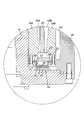
図16は、本発明の第4実施形態である真空ポンプ(ネジ溝ポンプ平行流タイプ)の断面図、図17(a)は図16のA部拡大図、図17(b)は加熱板の拡大図である。
FIG. 16 is a cross-sectional view of a vacuum pump (thread groove pump parallel flow type) according to a fourth embodiment of the present invention, FIG. 17A is an enlarged view of a portion A in FIG. 16, and FIG. It is an enlarged view.
図16の真空ポンプP4において、図1の真空ポンプP1と同一の部材には同一の符号を付し、その詳細説明は省略する。
In the vacuum pump P4 in FIG. 16, the same members as those in the vacuum pump P1 in FIG.
《図16の真空ポンプにおける加熱部の説明》
図16の真空ポンプP4もまた、図1の真空ポンプP1と同じく、ネジ溝排気部ステータ18A、18Bの下部に、生成物の付着を防止する手段として、加熱部20を設けている。具体的には、この図16の加熱部20もまた、図1の加熱部20と同じく、ネジ溝排気部ステータ18A、18Bとその下部に配置されているステータベース4との間に設けられている。
<< Description of Heating Unit in Vacuum Pump of FIG. 16 >>
Similarly to the vacuum pump P1 of FIG. 1, the vacuum pump P4 of FIG. 16 also includes a heating unit 20 as a means for preventing the product from adhering to the lower part of the thread groove exhaust part stators 18A and 18B. Specifically, the heating section 20 in FIG. 16 is also provided between the thread groove exhaust section stators 18A and 18B and the stator base 4 disposed below the same as the heating section 20 in FIG. Yes.
図16の加熱部20は、図17に示したように、内側のネジ溝排気部ステータ18A(以下必要に応じて「内側ネジ溝排気部ステータ18A」という)又は外側のネジ溝排気部ステータ18B(以下必要に応じて「外側ネジ溝排気部ステータ18B」という)のいずれかに当接する加熱板23と、ポンプベース1Dに配置されたヨーク25と、ヨーク25上に配置したコイル26と、を備えている。なお、ポンプベース1Dは、図1のベーススペーサ1Bとステータベース4が一体になったものである。
As shown in FIG. 17, the heating unit 20 in FIG. 16 includes an inner thread groove exhaust part stator 18A (hereinafter referred to as “inner thread groove exhaust part stator 18A”) or an outer thread groove exhaust part stator 18B. (Hereinafter referred to as “outer thread groove exhaust portion stator 18B”), a heating plate 23 that contacts any one of the above, a yoke 25 disposed on the pump base 1D, and a coil 26 disposed on the yoke 25. I have. The pump base 1D is a unit in which the base spacer 1B and the stator base 4 in FIG. 1 are integrated.
そして、前記コイル26に高周波の交流電流を流すことによる電磁誘導加熱により、図17の加熱部20は、加熱板23及びヨーク25を加熱し、これにより内側ネジ溝排気部ステータ18A、外側ネジ溝排気部ステータ18B、及びポンプベース1Dを加熱するように構成してある。更に、この加熱部20はポンプベース1Dからの伝熱によってステータコラム4も加熱することができる。
The heating unit 20 in FIG. 17 heats the heating plate 23 and the yoke 25 by electromagnetic induction heating by passing a high-frequency alternating current through the coil 26, whereby the inner screw groove exhaust portion stator 18A, outer screw groove, and the like. The exhaust part stator 18B and the pump base 1D are configured to be heated. Further, the heating unit 20 can also heat the stator column 4 by heat transfer from the pump base 1D.
図17の加熱部20では、ポンプベース1D側に凹部21を設け、凹部21の開口付近に前記加熱板23を配置するとともに、その凹部21内に前記ヨーク25を配置している。当該凹部21は、ステータコラム4の下部外周を1周する環状の形態であって、ポンプベース1D側からネジ溝排気部ステータ18A、18Bの端部に向かって開口するように形成してあるが、このような凹部21は省略することもできる。
17, a recess 21 is provided on the pump base 1D side, the heating plate 23 is disposed near the opening of the recess 21, and the yoke 25 is disposed in the recess 21. The concave portion 21 has an annular shape that goes around the lower outer periphery of the stator column 4 and is formed so as to open from the pump base 1D side toward the ends of the thread groove exhaust portion stators 18A and 18B. Such a recess 21 can be omitted.
図17の加熱部20における加熱板23は、前記凹部21の開口とネジ溝排気部ステータ18A、18Bの端部との間に位置し、かつ、内側ネジ溝排気部ステータ18A、外側ネジ溝排気部ステータ18Bのいずれかに当接する2以上の分離加熱板23A、23Bとして、複数に分離している。
The heating plate 23 in the heating unit 20 of FIG. 17 is located between the opening of the recess 21 and the ends of the thread groove exhaust part stators 18A and 18B, and the inner thread groove exhaust part stator 18A and the outer thread groove exhaust. The two or more separate heating plates 23A and 23B that are in contact with any one of the partial stators 18B are separated into a plurality.
前記のように複数に分離した加熱板23の具体的な構造例として、図16の真空ポンプP4では、内側ネジ溝排気部ステータ18A、外側ネジ溝排気部ステータ18Bが筒状であること、及び、凹部21が環状であることに対応して、ステータコラム4の下部外周を1周する内外2重のリング状板材を用意し、それらを内側の分離加熱板23A及び外側の分離加熱板23Bとして採用している。
As a specific structural example of the heating plate 23 separated into a plurality as described above, in the vacuum pump P4 of FIG. 16, the inner screw groove exhaust portion stator 18A and the outer screw groove exhaust portion stator 18B are cylindrical, and Corresponding to the concave portion 21 being annular, inner and outer double ring-shaped plate members that make one round of the lower outer periphery of the stator column 4 are prepared, and these are used as an inner separation heating plate 23A and an outer separation heating plate 23B. Adopted.
また、図16の真空ポンプP4では、内側の分離加熱板23Aは、内側ネジ溝排気部ステータ18Aの端部に直接当接して取り付けられることによって、内側ネジ溝排気部ステータ18Aを集中的に加熱する手段として機能するように設けている。一方、外側の分離加熱板23Bは、外側ネジ溝排気部ステータ18Bの端部に直接当接して取り付けられることによって、外側ネジ溝排気部ステータ18Bを集中的に加熱する手段として機能するように設けている。
Further, in the vacuum pump P4 of FIG. 16, the inner separation heating plate 23A is attached in direct contact with the end portion of the inner screw groove exhaust portion stator 18A, thereby intensively heating the inner screw groove exhaust portion stator 18A. It is provided so as to function as a means. On the other hand, the outer separation heating plate 23B is provided so as to function as a means for intensively heating the outer thread groove exhaust portion stator 18B by being attached in direct contact with the end portion of the outer thread groove exhaust portion stator 18B. ing.
図17の加熱部20でも、ヨーク25とコイル26との間は、その間に介在する絶縁板27により電気的に絶縁されている。また、図17の加熱部20における加熱板23とヨーク25も、鉄系材料(例えば、純鉄、S15C、S25C)や磁性を有するステンレス材料(例えば、フェライト系ステンレス材料、SUS430、SUS304、SUS420J2)等の磁性材料で形成され、前記コイル26は、良導体(例えば、銅材料)で形成されている。
Also in the heating unit 20 of FIG. 17, the yoke 25 and the coil 26 are electrically insulated by an insulating plate 27 interposed therebetween. Further, the heating plate 23 and the yoke 25 in the heating unit 20 of FIG. 17 are also made of an iron-based material (for example, pure iron, S15C, S25C) or a magnetic stainless steel material (for example, a ferritic stainless material, SUS430, SUS304, SUS420J2). The coil 26 is formed of a good conductor (for example, a copper material).
図17を参照すると、ポンプベース1Dには、コネクタ100を装着するためのコネクタ装着部101と、コネクタ装着部101から前記凹部21に連通する配線通し孔102と、配線通し孔102に通されてコイル26とコネクタ30とを接続するコイル26の配線103と、が設けられている。前記ヨーク25にも、前記コイル30の配線103や後述するセンサ51の配線を通すため、配線通し孔102を設けている。また、図17に示すコネクタ100、コネクタ装着部101、配線通し孔102、配線103、及びセンサ51の配線は水平位置(ベース1Bの外周に向ける方向)に配置しているが、垂直位置(ベース1Bの底面に向ける方向)に配置してもよい。
Referring to FIG. 17, the pump base 1 </ b> D is passed through the connector mounting portion 101 for mounting the connector 100, the wiring through hole 102 communicating from the connector mounting portion 101 to the recess 21, and the wiring through hole 102. A wiring 103 of the coil 26 that connects the coil 26 and the connector 30 is provided. The yoke 25 is also provided with a wiring through hole 102 for passing the wiring 103 of the coil 30 and the wiring of the sensor 51 described later. Also, the connector 100, the connector mounting portion 101, the wiring through hole 102, the wiring 103, and the sensor 51 shown in FIG. 17 are arranged in a horizontal position (direction toward the outer periphery of the base 1B), but a vertical position (base It may be arranged in a direction toward the bottom surface of 1B.
図17において、コネクタ100から配線103を介してコイル26に高周波の交流電流を流すと、コイル26と加熱板23(分離加熱板23A、23B)及びヨーク25とが電磁結合し、加熱板23及びヨーク25の内部に渦電流が発生する。そうすると、加熱板23やヨーク25には固有の電気抵抗があるため、加熱板23やヨーク25でジュール熱が発生する。また加熱板23やヨーク25では鉄損発熱、コイル26では銅損発熱が生じる。これらの熱のうち、特に加熱板23で発生した熱により内側及び外側ネジ溝排気部ステータ18A、18Bが優先的に加熱され、また、ヨーク25で発生した熱によりベーススペーサ1Bが優先的に加熱される。更に、ポンプベース1Dからの伝熱によってステータコラム4も加熱される。
In FIG. 17, when a high-frequency alternating current is passed from the connector 100 to the coil 26 via the wiring 103, the coil 26, the heating plate 23 ( separation heating plates 23A and 23B), and the yoke 25 are electromagnetically coupled, and the heating plate 23 and An eddy current is generated inside the yoke 25. Then, since the heating plate 23 and the yoke 25 have inherent electric resistance, Joule heat is generated in the heating plate 23 and the yoke 25. The heating plate 23 and the yoke 25 generate iron loss heat, and the coil 26 generates copper loss heat. Of these heats, the inner and outer screw groove exhaust part stators 18A and 18B are preferentially heated by heat generated by the heating plate 23, and the base spacer 1B is preferentially heated by heat generated by the yoke 25. Is done. Further, the stator column 4 is also heated by heat transfer from the pump base 1D.
内外の分離加熱板23A、23Bは、同じ材質の磁性材料で形成することによって、分離加熱板23A、23Bごとの発熱量が略同じになるように設定してもよいが、これとは別の実施形態として、それらを異なる材質の磁性材料で形成することにより、分離加熱板23A、23Bごとに発熱量が異なるように構成してもよい。
The inner and outer separation heating plates 23A and 23B may be set so that the heating values of the separation heating plates 23A and 23B are substantially the same by being formed of the same magnetic material. As an embodiment, by forming them with different magnetic materials, the heat generation amount may be different for each of the separate heating plates 23A and 23B.
内側ネジ溝排気部ステータ18A、外側ネジ溝排気部ステータ18Bは、その質量、材質、熱損失の違い等から熱容量が異なる場合がある。例えば、内側ネジ溝排気部ステータ18Aよりも外側ネジ溝排気部ステータ18Bの熱容量の方が大きい場合もある。この場合は、例えば、外側の分離加熱板23Bを純鉄系の材料で形成する一方、内側の分離加熱板23Aをステンレス材料で形成することで、内側の分離加熱板23Aの発熱量よりも外側の分離加熱板23Bの発熱量の方が大きくなるように設定することができる。これにより、加熱板23は、内側ネジ溝排気部ステータ18Aと外側ネジ溝排気部ステータ18Bが略同じ温度となるように加熱したり、それぞれの目標温度となるように加熱したりする等、ネジ溝排気部ステータ18A、18Bの熱容量に応じてネジ溝排気部ステータ18A、18Bを加熱することができる。
The inner screw groove exhaust portion stator 18A and the outer screw groove exhaust portion stator 18B may have different heat capacities due to differences in mass, material, heat loss, and the like. For example, the heat capacity of the outer thread groove exhaust portion stator 18B may be larger than that of the inner thread groove exhaust portion stator 18A. In this case, for example, the outer separation heating plate 23B is formed of a pure iron-based material, while the inner separation heating plate 23A is formed of a stainless steel material, so that the outer heating amount of the inner separation heating plate 23A is more than the amount of heat generated. The heat generation amount of the separate heating plate 23B can be set to be larger. As a result, the heating plate 23 is heated so that the inner screw groove exhaust portion stator 18A and the outer screw groove exhaust portion stator 18B have substantially the same temperature, or are heated to reach their respective target temperatures. The thread groove exhaust portion stators 18A and 18B can be heated according to the heat capacity of the groove exhaust portion stators 18A and 18B.
他に材質を変更する方法としては、材料に添加物を加える方法がある。例えば、分離加熱板の材料にセラミックスを添加し、材料の電気抵抗等の物性を部分的に変化させる。それによって、分離加熱板の全体のみならず一部分についての発熱量の変更が可能となる。
Other methods of changing the material include adding an additive to the material. For example, ceramics are added to the material of the separation heating plate to partially change physical properties such as electric resistance of the material. As a result, it is possible to change the amount of heat generated not only on the entire separation heating plate but also on a part thereof.
図18から図22は、先に説明した加熱板23の分離に関する他の実施形態の説明図である。
18 to 22 are explanatory views of other embodiments relating to the separation of the heating plate 23 described above.
これらの図18から図22に示された加熱板23もまた、先に説明した図16、図17の加熱板23と同じく、内外の分離加熱板23A、23Bとして分離しているが、その具体的な分離構成は以下のように異なる。
The heating plate 23 shown in FIGS. 18 to 22 is also separated as inner and outer separation heating plates 23A and 23B, similar to the heating plate 23 of FIGS. 16 and 17 described above. The typical separation configuration differs as follows.
図16、図17の加熱板23において、これを構成する内外の分離加熱板23A、23Bはその分離による隙間部G3(以下「分離隙間G3」という)を基準として左右対称の断面形状になっている。この一方、図18、図19の加熱板23において、これを構成する内外の分離加熱板23A、23Bは、その分離隙間G3を基準として左右非対称の断面形状であることにより、分離加熱板23A、23Bごとに発熱範囲及び発熱量が異なる構成になっている。
In the heating plate 23 of FIGS. 16 and 17, the inner and outer separation heating plates 23 </ b> A and 23 </ b> B constituting the heating plate 23 have a symmetrical cross-sectional shape with reference to a gap portion G <b> 3 (hereinafter referred to as “separation gap G <b> 3”). Yes. On the other hand, in the heating plate 23 of FIGS. 18 and 19, the inner and outer separation heating plates 23A and 23B constituting the heating plate 23 have a cross-sectional shape that is asymmetrical with respect to the separation gap G3. The heat generation range and the heat generation amount are different for each 23B.
特に、図18の加熱板23では、内外の分離加熱板23A、23Bの幅L1、L2が異なることにより、内外の分離加熱板23A、23Bは、その分離隙間G3を基準として左右非対称の断面形状になっている。ここで、例えば、内側ネジ溝排気部ステータ18Aよりも外側ネジ溝排気部ステータ18Bの熱容量の方が大きい場合は、外側ネジ溝排気部ステータ18Bの方が温度上昇し難い。この場合は、この図18のように、内側の分離加熱板23Aの幅L2よりも外側の分離加熱板23Aの幅L1を大きく設定する。これにより、加熱板23は、内側ネジ溝排気部ステータ18A、外側ネジ溝排気部ステータ18Bが略同じ温度となるように加熱したり、それぞれの目標温度となるように加熱したりする等、ネジ溝排気部ステータ18A、18Bの熱容量に応じてネジ溝排気部ステータ18A、18Bを加熱することができる。
In particular, in the heating plate 23 of FIG. 18, the inner and outer separation heating plates 23A and 23B have different widths L1 and L2, so that the inner and outer separation heating plates 23A and 23B are asymmetric in cross section with respect to the separation gap G3. It has become. Here, for example, when the heat capacity of the outer thread groove exhaust part stator 18B is larger than that of the inner thread groove exhaust part stator 18A, the temperature of the outer thread groove exhaust part stator 18B is less likely to increase. In this case, as shown in FIG. 18, the width L1 of the outer separation heating plate 23A is set larger than the width L2 of the inner separation heating plate 23A. Thereby, the heating plate 23 is heated so that the inner screw groove exhaust portion stator 18A and the outer screw groove exhaust portion stator 18B have substantially the same temperature, or are heated so as to have respective target temperatures. The thread groove exhaust portion stators 18A and 18B can be heated according to the heat capacity of the groove exhaust portion stators 18A and 18B.
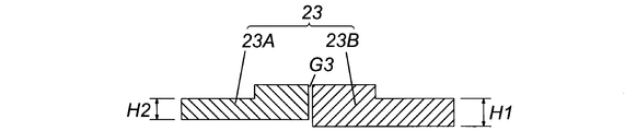
この一方、図19の加熱板23では、内外の分離加熱板23A、23Bの厚さH1、H2が異なることにより、内外の分離加熱板23A、23Bは、その分離隙間G3を基準として左右非対称の断面形状になっている。ここで、例えば、内側ネジ溝排気部ステータ18Aよりも外側ネジ溝排気部ステータ18Bの熱容量の方が大きい場合には、この図19のように、内側の分離加熱板23Aの厚さH2よりも外側の分離加熱板23Bの厚さH1を大きく設定する。これにより、加熱板23は、内側ネジ溝排気部ステータ18A、外側ネジ溝排気部ステータ18Bが略同じ温度となるように加熱したり、それぞれの目標温度となるように加熱したりする等、ネジ溝排気部ステータ18A、18Bの熱容量に応じてネジ溝排気部ステータ18A、18Bを加熱することができる。
On the other hand, in the heating plate 23 of FIG. 19, because the thicknesses H1 and H2 of the inner and outer separation heating plates 23A and 23B are different, the inner and outer separation heating plates 23A and 23B are asymmetrical with respect to the separation gap G3. It has a cross-sectional shape. Here, for example, when the heat capacity of the outer thread groove exhaust portion stator 18B is larger than that of the inner thread groove exhaust portion stator 18A, as shown in FIG. 19, it is larger than the thickness H2 of the inner separation heating plate 23A. The thickness H1 of the outer separation heating plate 23B is set large. Thereby, the heating plate 23 is heated so that the inner screw groove exhaust portion stator 18A and the outer screw groove exhaust portion stator 18B have substantially the same temperature, or are heated so as to have respective target temperatures. The thread groove exhaust portion stators 18A and 18B can be heated according to the heat capacity of the groove exhaust portion stators 18A and 18B.
図20の加熱板23において、これを構成する内外の分離加熱板23A、23Bは、内側の分離加熱板23Aを無垢材で形成し、外側の分離加熱板23Bを積層材で形成したものであり、これにより、内側の分離加熱板23Aよりも外側の分離加熱板23Bの方が発熱量は少なくなるように設定してある。この設定は、内側ネジ溝排気部ステータ18Aの熱容量よりも外側ネジ溝排気部ステータ18Bの熱容量の方が小さい場合の例であり、この例とは逆の場合は、内側の分離加熱板23Aを積層材で形成し、外側の分離加熱板23Bを無垢材で形成すればよい。
In the heating plate 23 of FIG. 20, the inner and outer separation heating plates 23A and 23B constituting the heating plate 23 are formed by forming the inner separation heating plate 23A from a solid material and the outer separation heating plate 23B from a laminated material. Thus, the heat generation amount of the outer separation heating plate 23B is set to be smaller than that of the inner separation heating plate 23A. This setting is an example in which the heat capacity of the outer thread groove exhaust part stator 18B is smaller than the heat capacity of the inner thread groove exhaust part stator 18A. In the opposite case, the inner separation heating plate 23A is What is necessary is just to form by the laminated material and to form the outer side separation heating plate 23B with a solid material.
前記のような積層材を採用した更に別の実施形態として、内外の分離加熱板23A、23Bを双方とも積層材で形成するとともに、その積層数を内外の分離加熱板23A、23Bで変えることにより、分離加熱板23A、23Bごとに発熱量が異なるように設定することも可能である。
As still another embodiment adopting the laminated material as described above, both the inner and outer separation heating plates 23A and 23B are formed of the lamination material, and the number of laminations is changed by the inner and outer separation heating plates 23A and 23B. It is also possible to set the heat generation amount different for each of the separate heating plates 23A and 23B.
図21、図22の加熱板23において、これを構成する内外の分離加熱板23A、23Bは、その分離した部分が上下方向に重なることによって、分離隙間G3を基準として左右非対称の断面形状であることに加え、当該分離隙間G3(加熱板23の分離した部分)がジグザグに折れ曲がった通路形状になっている。
In the heating plate 23 of FIGS. 21 and 22, the inner and outer separation heating plates 23A and 23B constituting the heating plate 23 have an asymmetrical cross-sectional shape with respect to the separation gap G3 as the separated portions overlap in the vertical direction. In addition, the separation gap G3 (part where the heating plate 23 is separated) has a passage shape bent in a zigzag manner.
前記分離隙間G3は空隙であるため、そのような分離隙間G3から加熱板23上部側へのコイル26の磁束漏れは避けられない。しかしながら、図21、図22のような分離加熱板23A、23Bの重ね構造によると、その分離隙間G3が前記のようにジグザグに折れ曲がった通路形状になることで、分離隙間G3の長さが増えるため、分離隙間G3から加熱板23上部側へのコイル26の磁束漏れを効果的に減少させることができる。
Since the separation gap G3 is a gap, leakage of magnetic flux of the coil 26 from the separation gap G3 to the upper side of the heating plate 23 is inevitable. However, according to the overlapping structure of the separation heating plates 23A and 23B as shown in FIG. 21 and FIG. 22, the separation gap G3 is increased in the length of the separation gap G3 because the separation gap G3 has a zigzag passage shape as described above. Therefore, the magnetic flux leakage of the coil 26 from the separation gap G3 to the upper side of the heating plate 23 can be effectively reduced.
特に、図21のような分離加熱板23A、23Bの重ね構造では、内外の分離加熱板23A、23Bの幅L1、L2も異なる構成になっているので、分離加熱板23A、23Bごとに発熱範囲及び発熱量が異なり、ネジ溝排気部ステータ18A、18Bの熱容量に応じて、ネジ溝排気部ステータ18A、18Bを加熱することもできる。
In particular, in the overlapping structure of the separation heating plates 23A and 23B as shown in FIG. 21, the widths L1 and L2 of the inner and outer separation heating plates 23A and 23B are different from each other. The heat generation amount is different, and the thread groove exhaust part stators 18A and 18B can be heated according to the heat capacity of the thread groove exhaust part stators 18A and 18B.
また、図16の真空ポンプP4では、前記加熱部20がポンプベース1Dよりも内側ネジ溝排気部ステータ18Aや外側ネジ溝排気部ステータ18Bを優先的に加熱できるようにする手段として、内側ネジ溝排気部ステータ18Aとステータコラム4との間に空隙G2を設けたり、外側ネジ溝排気部ステータ18Bとポンプベース1Dとの間に空隙G2を設けたりすることで、内側ネジ溝排気部ステータ18Aとステータコラム4との接触面積及び外側ネジ溝排気部ステータ18Bとポンプベース1Dとの接触面積が、いずれも小さくなるように設定している。
Further, in the vacuum pump P4 of FIG. 16, as the means for enabling the heating unit 20 to preferentially heat the inner thread groove exhaust part stator 18A and the outer thread groove exhaust part stator 18B over the pump base 1D, the inner thread groove is provided. By providing a gap G2 between the exhaust part stator 18A and the stator column 4, or providing a gap G2 between the outer thread groove exhaust part stator 18B and the pump base 1D, the inner thread groove exhaust part stator 18A The contact area with the stator column 4 and the contact area between the outer thread groove exhaust part stator 18B and the pump base 1D are set to be small.
図16、図17において、前記コイル26から前記加熱板23までの距離と、絶縁板27の厚みに相当するコイル26からヨーク25までの距離は、必要に応じて適宜変更することができるが、ネジ溝排気部ステータ18A、18B側での生成物の付着を効果的に防止する観点からは、その距離は、ヨーク25よりも加熱板23の方を有効に加熱できる距離に設定することが好ましい。
16 and 17, the distance from the coil 26 to the heating plate 23 and the distance from the coil 26 to the yoke 25 corresponding to the thickness of the insulating plate 27 can be appropriately changed as necessary. From the viewpoint of effectively preventing the adhesion of the product on the thread groove exhaust portion stators 18A and 18B, the distance is preferably set to a distance that can effectively heat the heating plate 23 rather than the yoke 25. .
図16、図17の加熱部20では、ヨーク25の断面形状を内側及び外側ネジ溝排気部ステータ18A、18Bに向かって上向きの溝形状とし、そのヨーク25の上端部を加熱板23に近づけて配置している。これにより、ヨーク25内のコイル26は磁性材料の加熱板23とヨーク25で囲まれた空間内に配置されるから、コイル26の磁束漏れは少ない。
In the heating section 20 of FIGS. 16 and 17, the sectional shape of the yoke 25 is a groove shape upward toward the inner and outer screw groove exhaust section stators 18 </ b> A and 18 </ b> B, and the upper end of the yoke 25 is brought close to the heating plate 23. It is arranged. As a result, the coil 26 in the yoke 25 is disposed in the space surrounded by the heating plate 23 and the yoke 25 made of magnetic material, and therefore the magnetic flux leakage of the coil 26 is small.
また、図16、図17の加熱部20では、ヨーク25と加熱板23との間に所定の隙間部を設けている。これにより、加熱板23で発生した熱がヨーク25を通じてポンプベース1D側に逃げ難くなり、加熱板23によるネジ溝排気部ステータ18A、18Bの優先的な加熱が可能になる。
16 and 17, a predetermined gap is provided between the yoke 25 and the heating plate 23. As a result, the heat generated in the heating plate 23 is unlikely to escape to the pump base 1D side through the yoke 25, and the preheating of the thread groove exhaust portion stators 18A and 18B by the heating plate 23 becomes possible.
図16の真空ポンプP4は、更に、図17にも示したように、ポンプ内の温度を検出する温度検出センサ51と、温度検出センサ51での検出値に基づいて加熱板23が所定の温度となるように制御する温度制御手段(図示省略)と、を備えている。なお、この図16の真空ポンプP4では、図17のように、外側ネジ溝排気部ステータ18Bに温度検出センサ51を取り付けているが、その取り付け位置に限定されることはない。例えば、内側ネジ溝排気部ステータ18Aや加熱板23に温度検出センサ51を取り付けてもよい。
Further, as shown in FIG. 17, the vacuum pump P <b> 4 of FIG. 16 has a temperature detection sensor 51 that detects the temperature in the pump, and the heating plate 23 has a predetermined temperature based on the detection value of the temperature detection sensor 51. Temperature control means (not shown) for controlling to be In the vacuum pump P4 of FIG. 16, the temperature detection sensor 51 is attached to the outer thread groove exhaust portion stator 18B as shown in FIG. 17, but the position is not limited to the attachment position. For example, the temperature detection sensor 51 may be attached to the inner thread groove exhaust portion stator 18 </ b> A or the heating plate 23.
図16、図17の加熱部20は、前記コイル26に取り付けたコイル温度検出センサ(図示なし)と、前記コイル温度検出センサでの検出値に基づいて前記コイルが所定の温度を超えないように制御する保護制御手段(図示省略)と、を備えてもよい。
The heating unit 20 in FIGS. 16 and 17 prevents a coil temperature from exceeding a predetermined temperature based on a coil temperature detection sensor (not shown) attached to the coil 26 and a detection value of the coil temperature detection sensor. Protection control means (not shown) for controlling.
また、図16の真空ポンプP4では、加熱板23に貫通孔を形成し、この貫通孔と凹部21と配線通し孔102とを通じて、温度検出センサ51及びコイル温度検出センサの配線をコネクタ100に接続しているが、これとは別の接続方式を採用してもよい。
Further, in the vacuum pump P4 of FIG. 16, a through hole is formed in the heating plate 23, and the temperature detection sensor 51 and the wiring of the coil temperature detection sensor are connected to the connector 100 through the through hole, the recess 21 and the wiring through hole 102. However, a different connection method may be adopted.
図16、図17の加熱部20において、凹部21とヨーク25の固定方式としては、例えば、凹部21内にヨーク25を圧入する方式、図示しないネジ止め固定する方式、あるいは、凹部21内にヨーク25を接着剤で固定する方式を採用することができる。
In the heating unit 20 of FIGS. 16 and 17, as a method of fixing the recess 21 and the yoke 25, for example, a method of press-fitting the yoke 25 into the recess 21, a method of fixing with screws (not shown), or a yoke in the recess 21 A method of fixing 25 with an adhesive can be employed.
また、図16、図17の加熱部20において、ヨーク25とコイル26の固定方式としては、ヨーク25内に樹脂等を充填することで、コイル26全体を樹脂等でモールドする方式を採用することができる。
In addition, in the heating unit 20 of FIGS. 16 and 17, as a method of fixing the yoke 25 and the coil 26, a method of molding the entire coil 26 with resin or the like by filling the yoke 25 with resin or the like is adopted. Can do.
さらに、図16、図17の加熱部20において、加熱板23と内側及び外側ネジ溝排気部ステータ18A、18Bの固定方式としては、加熱板23(分離加熱板23A、23B)の表面に設けた凸部を外側ネジ溝排気部ステータ18Bと内側ネジ溝排気部ステータ18Aとの間に嵌め込み、加熱板23とネジ溝排気部ステータ18A、18Bとを締結ボルトで固定する方式(ボルト固定方式)や、それらを接着剤で固定する方式(接着固定方式)等を採用することができ、また、前記ボルト固定方式と接着固定方式を併用してもよい。
Further, in the heating unit 20 of FIGS. 16 and 17, the heating plate 23 and the inner and outer screw groove exhaust part stators 18A and 18B are fixed on the surface of the heating plate 23 (separated heating plates 23A and 23B). A method in which the convex portion is fitted between the outer screw groove exhaust portion stator 18B and the inner screw groove exhaust portion stator 18A, and the heating plate 23 and the screw groove exhaust portion stators 18A and 18B are fixed with fastening bolts (bolt fixing method), A method of fixing them with an adhesive (adhesion fixing method) or the like may be employed, and the bolt fixing method and the adhesive fixing method may be used in combination.
図16、図17の加熱部20では、コイル26の配線103や温度センサ51及びコイル温度検出センサの配線を通すため、ヨーク25にも配線通し孔102を形成しているので、コイル26の磁束がその配線通し孔102を通じて外部に漏れる可能性がある。このため、この図16、図17の加熱部20では、磁束漏れ低減手段として、ヨーク25からコネクタ装着部101までの配線通し孔102全範囲に磁性材料からなるシールドパイプ200を装着し、また、コネクタ100の周囲に磁性材料からなるシールド板201を設置している。なお、シールドパイプ200とシールド板201いずれか一方だけでも、十分に磁束漏れを防止可能であるなら、他方を省略することもできる。
In the heating unit 20 of FIGS. 16 and 17, since the wiring through hole 102 is also formed in the yoke 25 in order to pass the wiring 103 of the coil 26 and the wiring of the temperature sensor 51 and the coil temperature detection sensor, the magnetic flux of the coil 26 is formed. May leak to the outside through the wiring hole 102. For this reason, in the heating unit 20 of FIGS. 16 and 17, a shield pipe 200 made of a magnetic material is attached to the entire range of the wiring through hole 102 from the yoke 25 to the connector mounting unit 101 as a magnetic flux leakage reducing unit. A shield plate 201 made of a magnetic material is installed around the connector 100. If only one of the shield pipe 200 and the shield plate 201 can sufficiently prevent magnetic flux leakage, the other can be omitted.
図16の真空ポンプP4は、加熱部20とポンプベース1Dとステータコラム4とを一体化した構造になっているが、これらは別部品として形成することもできる。
The vacuum pump P4 in FIG. 16 has a structure in which the heating unit 20, the pump base 1D, and the stator column 4 are integrated, but these can also be formed as separate parts.
以上説明したように、第4実施形態の真空ポンプP4にあっては、加熱部20の具体的な構成として、コイル26に交流電流を流すことによる電磁誘導加熱で加熱板23及びヨーク25を加熱し、これにより内側ネジ溝排気部ステータ18A、外側ネジ溝排気部ステータ18B、及びポンプベース1Dを加熱する機能を備えた。このため、加熱部20によるポンプベース1Dの加熱によってポンプベース1D内での生成物の付着も防止でき、これに加えて更に、ポンプベース1Dからの伝熱によってステータコラム4も加熱でき、ステータコラム4での生成物の付着も防止できることより、真空ポンプP4全体としての生成物の付着量を低減できる。
As described above, in the vacuum pump P4 of the fourth embodiment, as a specific configuration of the heating unit 20, the heating plate 23 and the yoke 25 are heated by electromagnetic induction heating by passing an alternating current through the coil 26. Thus, the inner screw groove exhaust portion stator 18A, the outer screw groove exhaust portion stator 18B, and the pump base 1D are heated. Therefore, the heating of the pump base 1D by the heating unit 20 can prevent the product from adhering in the pump base 1D. In addition, the stator column 4 can be heated by the heat transfer from the pump base 1D. 4 can also prevent the product from adhering, so that the amount of product adhering as a whole of the vacuum pump P4 can be reduced.
また、第4実施形態の真空ポンプP4では、配線通し孔102に磁性材料からなるシールドパイプ200を装着する構成や、コネクタ100の周囲に磁性材料からなるシールド板201を設置した構成を採用したため、シールドパイプ200やシールド板201によってコイル26の磁束漏れを減らすことができ、漏れ磁束によって真空ポンプP4内部の電装部品が誤動作する等、磁束漏れによる真空ポンプ電気系統のトラブルを効果的に防止することができる。
Further, in the vacuum pump P4 of the fourth embodiment, a configuration in which the shield pipe 200 made of a magnetic material is installed in the wiring through hole 102 and a configuration in which a shield plate 201 made of a magnetic material is installed around the connector 100 are adopted. The shield pipe 200 and the shield plate 201 can reduce the magnetic flux leakage of the coil 26, and effectively prevent troubles in the vacuum pump electrical system due to magnetic flux leakage, such as malfunction of the electrical components inside the vacuum pump P4 due to the leakage magnetic flux. Can do.
更に、第4実施形態の真空ポンプP4によると、加熱板20の具体的な構成として、加熱板23は、内側及び外側ネジ溝排気部ステータ18A、18Bのいずれかに当接する2以上の分離加熱板23A、23Bとして、複数に分離した構成を採用した。このため、例えば、当該加熱板23を内側及び外側ネジ溝排気部ステータ18A、18Bの端部に当接させて取付けるポンプ組立て段階において、加熱板23は2以上に分離した状態の分離加熱板23A、23Bとして内外それぞれのネジ溝排気部ステータ18A、18Bに個別に取り付けることができる。従って、内側及び外側ネジ溝排気部ステータ18A、18Bにおいてその長さ方向の加工寸法誤差や取付け寸法誤差が存在する場合でも、これらの誤差の影響を受けることなく、加熱板23を内側及び外側ネジ溝排気部ステータ18A、18Bに容易に取り付けることができるし、内側及び外側ネジ溝排気部ステータ18A、18Bにおける長さ方向の加工寸法や取り付け寸法を高精度なものとする必要がない点で、真空ポンプP4全体のコスト低減も図ることができる。
Furthermore, according to the vacuum pump P4 of the fourth embodiment, as a specific configuration of the heating plate 20, the heating plate 23 includes two or more separate heating units that contact either the inner or outer thread groove exhaust part stators 18A, 18B. As the plates 23A and 23B, a configuration separated into a plurality of parts was adopted. For this reason, for example, in the pump assembly stage in which the heating plate 23 is attached in contact with the ends of the inner and outer screw groove exhaust portion stators 18A and 18B, the heating plate 23 is separated into two or more separated heating plates 23A. , 23B can be individually attached to the inner and outer thread groove exhaust part stators 18A, 18B. Therefore, even if there are processing dimension errors and mounting dimension errors in the length direction of the inner and outer screw groove exhaust part stators 18A and 18B, the heating plate 23 is not affected by these errors, and the heating plate 23 is not affected by these errors. It can be easily attached to the groove exhaust part stators 18A, 18B, and it is not necessary to make the processing dimensions and attachment dimensions in the length direction in the inner and outer thread groove exhaust part stators 18A, 18B highly accurate. The overall cost of the vacuum pump P4 can also be reduced.
図18から図22に示した加熱板23の構造例や、内外の分離加熱板23A、23Bでその材質を異なる構成例は、それぞれ単独で採用できるが、必要に応じて、それらを組み合わせて採用してもよい。
The structural example of the heating plate 23 shown in FIG. 18 to FIG. 22 and the configuration examples in which the material is different between the inner and outer separation heating plates 23A and 23B can be adopted independently, but they are combined and used as necessary. May be.
また、第4実施形態の真空ポンプP4では、ネジ溝排気部Psがネジ溝ポンプ並行流タイプを構成しているが、このタイプのネジ溝排気部Psを限定するものではなく、ネジ溝排気部ステータを持つ全ての真空ポンプにも適応することができる。適用できる真空ポンプとしては、例えば、外側ネジ溝排気部ステータのみのネジ溝排気部Psを構成するタイプ、あるいは外側ネジ溝によって排気した後に内側ネジ溝によって繋ぎ排気するネジ溝排気部Psを構成するタイプがある。
Further, in the vacuum pump P4 of the fourth embodiment, the thread groove exhaust part Ps constitutes the thread groove pump parallel flow type, but this type of thread groove exhaust part Ps is not limited, and the thread groove exhaust part It can be applied to all vacuum pumps with a stator. As an applicable vacuum pump, for example, a type in which the thread groove exhaust part Ps of only the outer thread groove exhaust part stator is configured, or a thread groove exhaust part Ps that is exhausted by the inner thread groove after being exhausted by the outer thread groove is configured. There are types.
以上、説明した第1ないし第4実施形態の真空ポンプP1、P2、P3、P4では、翼排気部Ptとネジ排気部Psとを構成しているが、本発明は、ネジ排気部Psのみのものにも適用することができる。
In the vacuum pumps P1, P2, P3, and P4 of the first to fourth embodiments described above, the blade exhaust part Pt and the screw exhaust part Ps are configured. However, the present invention includes only the screw exhaust part Ps. It can also be applied to things.