JP2017005940A - Rotor structure of axial gap type rotary electric machine - Google Patents
Rotor structure of axial gap type rotary electric machine Download PDFInfo
- Publication number
- JP2017005940A JP2017005940A JP2015120159A JP2015120159A JP2017005940A JP 2017005940 A JP2017005940 A JP 2017005940A JP 2015120159 A JP2015120159 A JP 2015120159A JP 2015120159 A JP2015120159 A JP 2015120159A JP 2017005940 A JP2017005940 A JP 2017005940A
- Authority
- JP
- Japan
- Prior art keywords
- rotor
- rotor core
- passage
- permanent magnet
- gap type
- Prior art date
- Legal status (The legal status is an assumption and is not a legal conclusion. Google has not performed a legal analysis and makes no representation as to the accuracy of the status listed.)
- Abandoned
Links
Images


Abstract
Description
本発明は、アキシャルギャップ型回転電機(モータ、発電機、またはモータ兼発電機)のロータ構造に関する。 The present invention relates to a rotor structure of an axial gap type rotating electrical machine (motor, generator, or motor / generator).
従来、エアギャップを介してステータとロータとがロータ軸方向に対向するように配置され、これらステータおよびロータが中空円筒状のハウジング内に収容された構造のアキシャルギャップ型回転電機が公知である。 Conventionally, an axial gap type rotating electrical machine having a structure in which a stator and a rotor are arranged so as to face each other in the axial direction of the rotor via an air gap and the stator and the rotor are housed in a hollow cylindrical housing is known.
このアキシャルギャップ型回転電機(以下、「回転電機」と称する)において、ロータは、電磁鋼板等からなる円盤状のロータコアの片面に、複数の磁石がロータ軸周りに一定間隔で並ぶように配置された構造となっている。 In this axial gap type rotating electric machine (hereinafter referred to as “rotating electric machine”), the rotor is arranged on one side of a disk-shaped rotor core made of electromagnetic steel plate or the like so that a plurality of magnets are arranged at regular intervals around the rotor axis. It has a structure.
回転電機の駆動に伴ってロータの温度が上昇するが、ロータの温度が上昇すると、磁石の磁力が減少して回転電機の性能が低下する虞がある。そこで、磁石を強制冷却することが必要となる。 The temperature of the rotor rises as the rotating electrical machine is driven. However, when the rotor temperature rises, the magnetic force of the magnet may decrease and the performance of the rotating electrical machine may deteriorate. Therefore, it is necessary to forcibly cool the magnet.
特許文献1の図6〜8には、ロータコアの片面に、超伝導コイルからなる複数の磁石と、冷媒が通る冷媒流通管とが配置された構造のロータを備える回転電機が開示されている。
6 to 8 of
特許文献1に記載の回転電機によれば、ロータコアにおける冷媒流通管が通る波線状の領域を主に冷却することができるが、そのような狭い領域を冷却するだけでは、複数の磁石に対する冷却性能は十分とは言えず、改善の余地が残るものである。
According to the rotating electrical machine described in
本発明は、上記の事情に鑑みて成されたものであり、ロータが有する磁石に対する冷却性能を高めることができるアキシャルギャップ型回転電機のロータ構造を提供することを目的とする。 The present invention has been made in view of the above circumstances, and an object of the present invention is to provide a rotor structure of an axial gap type rotating electrical machine that can enhance the cooling performance of a magnet included in the rotor.
上記の課題を解決するために、本発明は、回転軸およびこの回転軸と共に回転するロータ本体を有するロータと、前記回転軸の軸方向に、前記ロータ本体に対向して配置されるステータとを備えるアキシャルギャップ型回転電機のロータ構造であって、前記ロータ本体は、円盤状のロータコアと、このロータコアにおける前記ステータ側の第1面に周方向に並んだ状態で固定される複数の永久磁石と、前記ロータコアにおける前記ステータとは反対側の第2面全体を覆い、かつ、前記第2面との間に冷却液流通空間を形成するジャケット部材と、前記ジャケット部材を前記ロータコアに固定する固定手段とを備え、前記回転軸は、前記冷却液流通空間に連通する冷却液の導入通路および導出通路を内部に備えていることを特徴とする、アキシャルギャップ型回転電機のロータ構造を提供する。 In order to solve the above-described problems, the present invention provides a rotor having a rotating shaft and a rotor body that rotates together with the rotating shaft, and a stator that is disposed in the axial direction of the rotating shaft so as to face the rotor body. A rotor structure of an axial gap type rotating electrical machine provided, wherein the rotor body includes a disk-shaped rotor core, and a plurality of permanent magnets fixed in a circumferentially aligned state on the first surface on the stator side of the rotor core. A jacket member that covers the entire second surface of the rotor core opposite to the stator and that forms a coolant flow space between the second surface and a fixing means for fixing the jacket member to the rotor core And the rotary shaft includes a coolant introduction passage and a discharge passage communicating with the coolant circulation space. Providing rotor structure Rugyappu type rotary electric machine.
本発明によれば、ロータコアの片面と当該片面全体を覆うジャケット部材との間に冷却液流通空間が形成されるため、この冷却液流通空間に冷却液を流すことにより、ロータコアおよびロータコアに固定された複数の永久磁石を効率よく冷却することができ、磁石に対する冷却性能を高めることができる。さらに、固定手段により、ジャケット部材をロータコアに固定することができる。 According to the present invention, the coolant circulation space is formed between one surface of the rotor core and the jacket member that covers the entire one surface, so that the coolant is allowed to flow into the coolant circulation space, thereby being fixed to the rotor core and the rotor core. The plurality of permanent magnets can be efficiently cooled, and the cooling performance for the magnets can be enhanced. Further, the jacket member can be fixed to the rotor core by the fixing means.
本発明においては、前記ジャケット部材は、前記ロータコアに対向して当該ロータコアとの間に前記冷却液流通空間を形成する基板部と、当該基板部の中心部に設けられる内周壁と、前記基板部の外周部に設けられる外周壁とを備え、前記冷却液流通空間は、前記内周壁と前記外周壁との間で周方向に連続して形成されていることが好ましい。 In the present invention, the jacket member includes a substrate portion that faces the rotor core and forms the coolant circulation space with the rotor core, an inner peripheral wall provided in a central portion of the substrate portion, and the substrate portion It is preferable that the coolant circulation space is continuously formed in the circumferential direction between the inner peripheral wall and the outer peripheral wall.
この構成によれば、ロータコアと冷却液との接触面積が大きくなるため、永久磁石に対する冷却能力を高めることができる。 According to this configuration, since the contact area between the rotor core and the coolant is increased, the cooling capacity for the permanent magnet can be increased.
本発明においては、前記ジャケット部材は、前記冷却液流通空間を周方向に複数の区画に仕切る第1仕切壁および第2仕切壁を有し、前記第1仕切壁は、前記内周壁から径方向外側へ延び、かつ、前記外周壁との間に隙間を有し、前記第2仕切壁は、前記外周壁から径方向内側へ延び、かつ、前記内周壁との間に隙間を有し、前記第1仕切壁と前記第2仕切壁とが、周方向に交互に配置されていることが好ましい。 In the present invention, the jacket member has a first partition wall and a second partition wall that partition the coolant circulation space into a plurality of sections in the circumferential direction, and the first partition wall is radially extending from the inner peripheral wall. Extending outward and having a gap with the outer peripheral wall, the second partition wall extending radially inward from the outer peripheral wall and having a gap with the inner peripheral wall, It is preferable that the first partition wall and the second partition wall are alternately arranged in the circumferential direction.
この構成によれば、冷却液流通空間に導入された冷却液は、第1仕切壁と外周壁との間の隙間と、第2仕切壁と内周壁との間の隙間とを交互に通過するように蛇行して流れるため、冷却液流通空間内を径方向内側と径方向外側とで均一に流れることができ、その結果、ロータコアおよび複数の磁石を径方向内側と径方向外側とで均一に冷却することができる。 According to this configuration, the coolant introduced into the coolant circulation space alternately passes through the gap between the first partition wall and the outer peripheral wall and the gap between the second partition wall and the inner peripheral wall. Thus, it can flow in the coolant circulation space uniformly on the radially inner side and the radially outer side, and as a result, the rotor core and the plurality of magnets can be evenly distributed on the radially inner side and the radially outer side. Can be cooled.
本発明においては、前記固定手段は、前記永久磁石、前記ロータコア、および前記ジャケット部材を挟み込むクランプ部材であり、前記ロータコアの径方向に延びる一対のアーム部と、前記ロータコアの径方向外側の位置で前記一対のアーム部同士を連結する連結部とを有することが好ましい。 In the present invention, the fixing means is a clamp member that sandwiches the permanent magnet, the rotor core, and the jacket member, and a pair of arm portions extending in the radial direction of the rotor core and a position radially outside the rotor core. It is preferable to have a connecting portion that connects the pair of arm portions.
この構成によれば、一対のアーム部によって永久磁石およびジャケット部材をロータコア側に押さえ込むことができるため、永久磁石およびジャケット部材の固定強度を高めることができる。 According to this configuration, since the permanent magnet and the jacket member can be pressed to the rotor core side by the pair of arm portions, the fixing strength of the permanent magnet and the jacket member can be increased.
本発明においては、前記クランプ部材の前記ジャケット部材側のアーム部の位置は、前記周方向における前記第1仕切壁および前記第2仕切壁の位置と一致していることが好ましい。 In this invention, it is preferable that the position of the arm part by the side of the said jacket member of the said clamp member corresponds with the position of the said 1st partition wall and the said 2nd partition wall in the said circumferential direction.
この構成によれば、ジャケット部材側のアーム部をジャケット部材に固定するために、当該アーム部をジャケット部材の基板部側から第1仕切壁および第2仕切壁に埋め込むことが可能になるので、ジャケット部材側のアーム部の位置が第1仕切壁および第2仕切壁の位置と一致していない場合と比べて、冷却液流通空間の流路面積をより大きくすることができ、冷却性能を高めることができる。詳しく説明すると、ジャケット部材側のアーム部の位置が第1仕切壁および第2仕切壁の位置と一致していない場合に、そのアーム部をジャケット部材に固定するためには、アーム部を基板部のみに埋め込む必要があり、そのためには、埋め込み位置における基板部の厚み(被り深さ)を十分に確保するべくその埋め込み位置において基板部をロータコア側へ隆起させる必要があり、その分、冷却液流通空間の流路面積が小さくなる虞があるが、本構成によれば、そのような不都合は生じない。 According to this configuration, in order to fix the arm portion on the jacket member side to the jacket member, the arm portion can be embedded in the first partition wall and the second partition wall from the substrate portion side of the jacket member. Compared with the case where the position of the arm part on the jacket member side does not coincide with the position of the first partition wall and the second partition wall, the flow passage area of the coolant circulation space can be increased, and the cooling performance is improved. be able to. More specifically, in order to fix the arm part to the jacket member when the position of the arm part on the jacket member side does not coincide with the position of the first partition wall and the second partition wall, the arm part is the substrate part. For this purpose, it is necessary to raise the substrate portion toward the rotor core at the embedding position in order to sufficiently secure the thickness (cover depth) of the substrate portion at the embedding position. Although there is a concern that the flow passage area of the circulation space may be reduced, this configuration does not cause such inconvenience.
本発明においては、前記クランプ部材の前記永久磁石側のアーム部は、前記周方向に互いに隣接する前記永久磁石をこれらの周方向端部の位置で押さえ込むことが好ましい。 In this invention, it is preferable that the arm part by the side of the said permanent magnet of the said clamp member presses down the said permanent magnet adjacent to the said circumferential direction in the position of these circumferential direction edge parts.
この構成によれば、互いに隣接する永久磁石を共通のクランプ部材でロータコア側に押さえ込むことができるため、合理的な構成となる。 According to this configuration, since the permanent magnets adjacent to each other can be pressed to the rotor core side by the common clamp member, the configuration is rational.
本発明においては、前記周方向に互いに隣接する前記永久磁石の隙間に、その隙間を塞ぐ状態で軟磁性体が配置され、前記クランプ部材の前記永久磁石側のアーム部は、前記永久磁石および前記軟磁性体を、その境界部分の位置で押さえ込むことが好ましい。 In the present invention, a soft magnetic body is disposed in a gap between the permanent magnets adjacent to each other in the circumferential direction so as to close the gap, and the arm portion on the permanent magnet side of the clamp member includes the permanent magnet and the It is preferable to hold down the soft magnetic body at the boundary portion.
この構成によれば、永久磁石および軟磁性体をクランプ部材でロータコア側に押さえ込むことができる。さらに、アーム部が非磁性体で構成される場合であっても、アーム部が軟磁性体全体を覆ってしまうことがなく、軟磁性体に磁界が作用することによるリラクタンストルクの向上を図ることができる。 According to this configuration, the permanent magnet and the soft magnetic body can be pressed to the rotor core side by the clamp member. Furthermore, even when the arm portion is made of a non-magnetic material, the arm portion does not cover the entire soft magnetic material, and the reluctance torque is improved by applying a magnetic field to the soft magnetic material. Can do.
本発明においては、前記永久磁石は、前記ロータコアの径方向に複数に分割されていることが好ましい。 In this invention, it is preferable that the said permanent magnet is divided | segmented into plurality in the radial direction of the said rotor core.
この構成によれば、永久磁石を複数に分割することで、永久磁石の発熱の主要因である渦電流損を低減することができ、さらに、アーム部で永久磁石を確実に保持することができる。 According to this configuration, by dividing the permanent magnet into a plurality of parts, it is possible to reduce eddy current loss, which is a main cause of heat generation of the permanent magnet, and to securely hold the permanent magnet at the arm portion. .
本発明においては、前記永久磁石は、前記ロータコアの径方向に延びる複数の分割溝および周方向に延びる複数の分割溝を有しており、各分割溝の溝底は、前記永久磁石の前記軸方向の中央部よりも前記ロータコア側に位置することが好ましい。 In the present invention, the permanent magnet has a plurality of divided grooves extending in the radial direction of the rotor core and a plurality of divided grooves extending in the circumferential direction, and the groove bottom of each divided groove is the shaft of the permanent magnet. It is preferable to be located on the rotor core side with respect to the central portion in the direction.
この構成によれば、分割溝の溝底が、軸方向における永久磁石の中央部よりもロータコア側に位置することで、永久磁石がバラバラになることを防止してロータコアへの永久磁石の組み付け作業の効率化を図りつつ、渦電流損を低減することができる。 According to this configuration, since the groove bottom of the split groove is positioned on the rotor core side with respect to the central portion of the permanent magnet in the axial direction, the permanent magnet is prevented from falling apart and the permanent magnet is assembled to the rotor core. The eddy current loss can be reduced while improving the efficiency.
本発明においては、前記ジャケット部材は、前記導入通路から前記冷却液流通空間に冷却液を取り入れるための取入口と、前記冷却液流通空間から前記導出通路へ排出するための排出口とを前記内周壁に各々2つ備え、前記2つの取入口は、前記径方向の互いに反対側に配置され、前記2つの排出口は、前記径方向の互いに反対側に配置されていることが好ましい。 In the present invention, the jacket member has an intake port for taking in the coolant from the introduction passage into the coolant circulation space and a discharge port for discharging the coolant from the coolant circulation space to the outlet passage. Preferably, two peripheral walls are provided, the two intake ports are arranged on the opposite sides in the radial direction, and the two discharge ports are arranged on the opposite sides in the radial direction.
この構成によれば、冷却液が2つの取入口から冷却液流通空間内に取り入れられるともに、冷却液流通空間内の冷却液が2つの排出口から排出され、しかも、2つの取入口が径方向の互いに反対側の位置に設けられ、2つの排出口が径方向の互いに反対側の位置に設けられるため、冷却液流通路内における周方向での冷却液の温度差が抑制され、永久磁石に対する冷却性能をさらに高めることができる。 According to this configuration, the coolant is taken into the coolant circulation space from the two inlets, the coolant in the coolant circulation space is discharged from the two outlets, and the two inlets are in the radial direction. Are provided at positions opposite to each other, and the two discharge ports are provided at positions opposite to each other in the radial direction, so that the temperature difference of the coolant in the circumferential direction in the coolant flow passage is suppressed, and The cooling performance can be further enhanced.
本発明においては、前記軸方向における前記ロータコアの位置を境として、前記導入通路は前記永久磁石側に配置され、前記導出通路は前記ジャケット部材側に配置されていることが好ましい。 In the present invention, it is preferable that the introduction passage is disposed on the permanent magnet side and the lead-out passage is disposed on the jacket member side with the position of the rotor core in the axial direction as a boundary.
この構成によれば、ジャケット部材と比べて高温になりやすい永久磁石側に導入通路を配置し、ジャケット部材側に導出通路を配置することにより、永久磁石の熱を回転軸を介して導入通路内の冷却液に放熱することができるため、永久磁石に対する冷却性能をさらに高めることができる。 According to this configuration, the introduction passage is disposed on the permanent magnet side, which is likely to be hotter than the jacket member, and the lead-out passage is disposed on the jacket member side, so that the heat of the permanent magnet is transferred to the inside of the introduction passage via the rotating shaft. Therefore, the cooling performance for the permanent magnet can be further enhanced.
本発明においては、前記アキシャルギャップ型回転電機は、2つの前記ロータが、前記軸方向における1つの前記ステータの両側に配置された構造を有し、前記導入通路と前記導出通路とは、前記回転軸内で並列に配置され、前記導入通路および前記導出通路は、各前記ロータの前記冷却液流通空間に連通していることが好ましい。 In the present invention, the axial gap type rotating electrical machine has a structure in which two rotors are arranged on both sides of one stator in the axial direction, and the introduction passage and the lead-out passage are the rotation It is preferable that the lead-in passage and the lead-out passage are arranged in parallel in a shaft and communicate with the coolant circulation space of each rotor.
この構成によれば、いわゆるダブルロータ構造のアキシャルギャップ型回転電機において、両ロータを均一に冷却することができる。 According to this configuration, in the axial gap type rotating electrical machine having a so-called double rotor structure, both rotors can be uniformly cooled.
本発明においては、前記2つのロータの前記冷却液流通空間が、前記導入通路および前記導出通路を介して並列に接続され、または、前記導入通路に接続された導入側中継通路および前記導出通路に接続された導出側中継通路を介して並列に接続され、一方のロータと他方のロータとは、前記導入通路または前記導入側中継通路との接続部の流路面積が互いに異なることが好ましい。 In the present invention, the coolant circulation spaces of the two rotors are connected in parallel via the introduction passage and the lead-out passage, or are connected to the introduction-side relay passage and the lead-out passage connected to the introduction passage. It is preferable that the one rotor and the other rotor are connected in parallel via the connected lead-out side relay passages, and that the flow passage areas of the connection portions with the introduction passage or the introduction-side relay passage are different from each other.
この構成によれば、一方のロータと他方のロータとで、導入通路または導入側中継通路との接続位置が異なる場合に、その接続部の流路面積を相違させることで、一方のロータと他方のロータとで冷却液流通空間に流入する冷却液の流量を等しくすることができる。詳しく説明すると、例えば、一方のロータが他方のロータよりも導入通路における上流側に接続されている場合に、接続位置の違いで接続部同士の間に圧力損失による圧力差が生じて、流量に差が生じる可能性があるが、接続部の流路面積を相違させることで、その圧力差を流路面積の差で補って流量を等しくすることが可能となり、その結果、上流側のロータと下流側のロータとで、永久磁石に対する冷却能力を同じにすることができる。 According to this configuration, when the connection position of the introduction passage or the introduction-side relay passage is different between one rotor and the other rotor, the flow area of the connection portion is made different so that the one rotor and the other rotor The flow rate of the coolant flowing into the coolant flow space can be made equal by the rotor of the same. More specifically, for example, when one rotor is connected to the upstream side of the introduction passage from the other rotor, a pressure difference due to pressure loss occurs between the connection portions due to the difference in the connection position, and the flow rate is reduced. There is a possibility that a difference will occur, but by making the flow area of the connection part different, it becomes possible to compensate the pressure difference with the difference in the flow area and make the flow rate equal. The cooling capacity for the permanent magnet can be made the same in the downstream rotor.
以上説明したように、本発明によれば、アキシャルギャップ型回転電機のロータが有する磁石に対する冷却性能を高めることができる。 As described above, according to the present invention, it is possible to improve the cooling performance for the magnet of the rotor of the axial gap type rotating electrical machine.
以下、添付図面を参照しながら本発明の好ましい実施形態について詳述する。 Hereinafter, preferred embodiments of the present invention will be described in detail with reference to the accompanying drawings.
(第1実施形態)
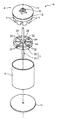
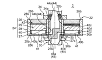
図1は、本発明の第1実施形態に係る回転電機1Aの分解斜視図である。同図に示す回転電機1Aは、回転軸20を中心に備えるロータ2と、当該ロータ2の後記ロータ本体22の一方側(永久磁石26が設けられている側)に位置し、ロータ本体22に対して回転軸20の軸方向に所定間隔を隔てて対向するステータ4と、これらロータ2及びステータ4が収容される円筒状のハウジング6とを備えた、いわゆる1ロータ1ステータ型のアキシャルギャップ型回転電機である。なお、以下の説明では、回転軸20と平行な方向を「軸方向」、回転軸20と直交する方向を「径方向」、回転軸20(ロータ2)の回転方向を「周方向」と称する。
(First embodiment)
FIG. 1 is an exploded perspective view of a rotating
ステータ4は、図1に示されるように、上記軸方向と平行な軸周りに電磁鋼板が渦巻き旋回状に巻かれた構造のバックヨーク12と、周方向に配列された状態でこのバックヨーク12上に固定される複数のステータコア(図示略)と、各ステータコアに装着(巻回)されるコイル11と、バックヨーク12の外側に固定されるエンドプレート14とを備えている。
As shown in FIG. 1, the stator 4 includes a
ステータ4は、円筒状の上記ハウジング6の一方側からその内側に挿入され、エンドプレート14を介してこのハウジング6に固定されている。
The stator 4 is inserted from one side of the cylindrical housing 6 to the inside thereof, and is fixed to the housing 6 via an
ハウジング6の他方側の端部にもエンドプレート14が設けられ、このエンドプレート14により他方側端部の開口部が塞がれている。
An
ロータ2は、円盤状のロータ本体22と、このロータ本体22の中心を貫通する回転軸20と、ロータ本体22を上下(軸方向)両側から挟み込んだ状態で当該回転軸20に固定するためのクランプ部材32とを含む。
The
ロータ2は、ステータ4に対向するようにハウジング6内に配置され、かつ回転軸20が、各エンドプレート14に保持されたベアリング16に挿入されることで、エンドプレート14に回転自在に支持されている。
The
図6に示されるように、回転軸20は、後述の冷却液流通空間41に連通する冷却液の導入通路44および導出通路45を内部に備えている。
As shown in FIG. 6, the
軸方向におけるロータコア25の位置を境として、導入通路44は永久磁石26側に配置され、導出通路45はジャケット部材40側に配置されている。
With the position of the
図6に示されるように、導入通路44は、回転軸20内を軸方向に延びる1本のメイン通路44aと、このメイン通路44aから分岐する2本の分岐通路44b(図8参照)とを備えている。2本の分岐通路44bは、互いに径方向の反対側に配置されている。
As shown in FIG. 6, the
図6に示されるように、導出通路45は、回転軸20内を軸方向に延びる1本のメイン通路45aと、このメイン通路45aから分岐する2本の分岐通路45b(図8参照)とを備えている。2本の分岐通路45bは、互いに径方向の反対側に配置されている。
As shown in FIG. 6, the lead-
ロータ本体22は、図2〜図4に示されるように、ロータ主部材24と、このロータ主部材24を軸方向両側から挟み込むクランプ部材32とを備えている。図2,3に示される例では、8つのクランプ部材32a〜32hが設けられている。
As shown in FIGS. 2 to 4, the rotor
ロータ主部材24は、帯状の電磁鋼板が渦巻旋回状に巻回されることにより概略円盤状に形成されたロータコア25と、このロータコア25のステータ4側の面である第1面(図4〜7では上面)に固定される複数の永久磁石26と、ロータコア25におけるステータ4とは反対側の面である第2面(図4〜7では下面)全体を覆い、かつ、第2面との間に冷却液流通空間41(図4〜10参照)を形成するジャケット部材40(図3参照)と、ロータコア25の中心部に設けられかつ回転軸20に外嵌される内筒部材27と、ロータコア25に外嵌される外筒部材28と、を含んでいる。内筒部材27および外筒部材28は、非磁性材料(オーステナイト系ステンレス、アルミ等)で形成されている。
The rotor
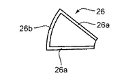
永久磁石26は、図11に示されるように平面視略扇型であり、内筒部材27の外周面に沿って周方向に並ぶようにロータコア25の上面に、液漏れ防止シート42(図4〜7参照)を介して配列され、各々接着剤により液漏れ防止シート42の上面に固定されている。図2に示される例では、液漏れ防止シート42の上面に8個の永久磁石26が固定されている。液漏れ防止シート42は、ジャケット部材40とロータコア25との間を流れる冷却液がロータコア25を通じて永久磁石26まで漏れ出すのを防止するためのシートである。
As shown in FIG. 11, the
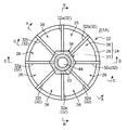
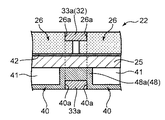
図4〜10に示されるように、ジャケット部材40は、ロータコア25に対向してロータコア25との間に冷却液流通空間41を形成する基板部40bと、基板部40bの中心部に設けられる内周壁40cと、基板部40bの外周部に設けられる外周壁40dとを備えている。冷却液流通空間41は、内周壁40cと外周壁40dとの間で周方向に連続して形成されている。
As shown in FIGS. 4 to 10, the
内周璧40cは、導入通路44の分岐通路44bから冷却液流通空間41に冷却液を取り入れるための取入口401(図6参照)と、冷却液流通空間41から導出通路45の分岐通路45bへ冷却液を排出するための排出口402(図6参照)とを各々2つ備えている。
The inner
2つの取入口401は、互いに径方向の反対側に配置され、2つの排出口402は互いに径方向の反対側に配置されている。
The two
また、図8に示されるように、ジャケット部材40は、冷却液流通空間41を周方向に複数の区画に仕切る第1仕切壁48a、第2仕切壁48b、および第3仕切璧48cを有している。以下の説明では、第1仕切璧48a、第2仕切璧48b、および第3仕切璧48cを総称して、仕切璧48と称する。
Further, as shown in FIG. 8, the
第1仕切壁48aは、内周壁40cから径方向外側へ延び、かつ、外周壁40dとの間に隙間49(図8,9参照)を有している。第2仕切壁48bは、外周壁40dから径方向内側へ延び、かつ、内周壁40cとの間に隙間49(図8参照)を有している。第3仕切璧48cは、内周璧40cと外周璧40dとを繋ぐように径方向に延びている。
The
第1仕切壁48aと第2仕切壁48bとは、周方向に交互に配置されている。図8に示される例では、ジャケット部材40は、4つの第1仕切璧48aと、2つの第2仕切璧48bと、2つの第3仕切璧48cとを有している。2つの第3仕切璧48cは、同一直線上に位置する状態で、回転軸20に対して互いに反対側に位置している。この直線を境とする一方側(図8における上側)および他方側(図8における下側)に、各々、2つの第1仕切璧48aおよび1つの第2仕切璧48bが等間隔で配置され、この1つの第2仕切璧48bは2つの第1仕切璧48aの間に配置されている。周方向に互いに隣接する仕切璧48は、回転軸20周りに互いに45度の角度をなしている。
The
第3仕切璧48cは、径方向全体に亘り、上側(ロータコア25側)の面がロータコア25の上記第2面に当接している。これにより、第3仕切璧48cの全体が冷却液の流れを堰き止めている。
In the
第1仕切璧48aは、図8,9に示されるように、その径方向外側の先端部が内周壁40cと外周壁40dとの中間位置よりも外側に位置しており、径方向全体に亘り、上側(ロータコア25側)の面がロータコア25の上記第2面に当接している。第1仕切璧48aの先端部と外周壁40dとの間の区間では、図9に示されるように、基板部40bがロータコア25側に隆起しており、その隆起部の頂部とロータコア25との間には隙間49が設けられている。
As shown in FIGS. 8 and 9, the
第2仕切璧48bは、図8に示されるように、その径方向外側の先端部が内周壁40cと外周壁40dとの中間位置よりも内側に位置しており、径方向全体に亘り、上側(ロータコア25側)の面がロータコア25の上記第2面に当接している。第2仕切璧48bの先端部と内周壁40cとの間の区間では、基板部40bがロータコア25側に隆起しており、その隆起部の頂部とロータコア25との間には隙間49が設けられている。
As shown in FIG. 8, the
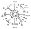
図9,10に示されるように、ジャケット部材40の下面(ロータコア25とは反対側の面)には、内周璧40cから外周壁40dに亘って径方向に延びる溝部40aが形成されている。この溝部40aの周方向の位置は、第1仕切璧48a、第2仕切璧48b、および第3仕切璧48cと同じ位置に設定されている。この溝部40aは、後述のアーム部33aが嵌め込まれる部分である。
As shown in FIGS. 9 and 10, a
外筒部材28は、図4〜7に示されるように、ロータコア25、これに固定された液漏れ防止シート42、永久磁石26、およびジャケット部材40に外嵌する状態で当該ロータコア25等の外側に配置されている。
As shown in FIGS. 4 to 7, the
図4〜7に示されるように、外筒部材28は、ロータコア25の厚みに液漏れ防止シート42の厚み、永久磁石26の厚み、およびジャケット部材40の厚みを加えた寸法と略同等の軸方向寸法を有している。外筒部材28の上下両端には、その全周に亘って内向きに突出する鍔部28b(図6参照)が設けられており、これら鍔部28bによってロータコア25の上面に固定された液漏れ防止シート42および永久磁石26と、下面に固定されたジャケット部材40とがロータコア25側に押さえ込まれている。
As shown in FIGS. 4 to 7, the
図6,10,11に示されるように、各永久磁石26の径方向外縁部には周方向に伸びる段差部26bが形成されており、上記鍔部28bは、反ロータコア25側からこの段差部26bに係合することで、外筒部材28の上端面と各永久磁石26の表面とが面一となり、外筒部材28の下端面とジャケット部材40の表面とが面一となっている。内筒部材27の軸方向寸法も外筒部材28の軸方向寸法と同等であり、従って、内筒部材27、外筒部材28およびこれらの間に位置する各永久磁石26の各上面は互いに面一であり、各下面も同様に面一である。
As shown in FIGS. 6, 10, and 11, a
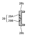
なお、図15に示されるように、上記外筒部材28は、軸方向に嵌合される2つのパーツ29A、29Bにより構成されており、この構成により、ロータコア25の上面に固定された液漏れ防止シート42および永久磁石26と、下面に固定されたジャケット部材40とを上記鍔部28bにより上下両側から押さえ込むことが可能となっている。
As shown in FIG. 15, the
クランプ部材32は、ロータコア25と、その上面に固定された各永久磁石26と、その下面に固定されたジャケット部材40とを上下両側から一体に挟み込むことにより、ロータコア25と永久磁石26との固定強度、および、ロータ本体25とジャケット部材40との固定強度を補強するものである。
The
このクランプ部材32は、図2〜4,7に示されるように、周方向における各永久磁石26の端部の位置でそれぞれロータ主部材24をその径方向外側からくわえこむように当該ロータ主部材24に装着されている。図2,3に示される例では8個のクランプ部材32がロータ主部材24に装着されている。
As shown in FIGS. 2 to 4, the
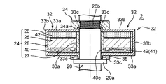
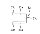
各クランプ部材32は、図4,5,7,12に示されるように、ロータ主部材24の上下両側の位置で当該ロータ主部材24の径方向に延びる一対のアーム部33a、33aと、これらアーム部33a、33aをロータ主部材24の径方向外側の位置で連結する連結部33bとを有する側面視コ字型の形状を有している。
As shown in FIGS. 4, 5, 7, and 12, each
クランプ部材32の材質は、特に限定されるものではないが、クランプ部材32に渦電流損が発生するのを抑えることができる材料から構成されることが好ましく、例えば、アルミニウム、ステンレス、合成樹脂などの非磁性体、または軟磁性体で構成することができる。また、クランプ部材32は、例えば、これらの材料から構成した薄板を積層して成形することにより構成することができる。
The material of the
クランプ部材32の下側(ジャケット部材40側)のアーム部33aの位置は、周方向における第1仕切壁48a、第2仕切壁48b、および第3仕切璧48cの位置と一致している。下側のアーム部33aは、クランプ部材40の溝部40aに嵌め込まれた状態で、クランプ部材40をロータコア25側に押さえ込んでいる。アーム部33aの上下方向の厚さは、溝部40aの深さと同じに設定されているため、アーム部33aの下面は、クランプ部材40の下面と面一になっている。
The position of the
このクランプ部材32は、図2,9〜11に示されるように、ロータコア25の上側において、周方向に隣接する一組の永久磁石26の端部を永久磁石26側のアーム部33aで押さえ込むとともに、ロータコア25の下側において、ジャケット部材40における仕切璧48をジャケット部材40側のアーム部33aで押さえ込むようにロータ主部材24に装着されている。この構成により、ロータコア25の上側の各永久磁石26は、2つのクランプ部材32によってロータコア25側に押さえ込まれている。
As shown in FIGS. 2 and 9 to 11, the
なお、図9〜11に示されるように、各永久磁石26の周方向両端部には径方向に伸びる段差部26aがそれぞれ形成されており、クランプ部材32の永久磁石26側のアーム部33aは、隣接する永久磁石26の間に介在した状態で当該段差部26bに反ロータコア25側から係合している。この構成により、アーム部33aの表面と各永久磁石26の表面とが面一となっている。
As shown in FIGS. 9 to 11,
また、図13,14に示されるように、外筒部材28のうち、隣接する永久磁石26の間に対応する位置には各々クランプ部材32に対応する形状の溝28aが形成されており、内筒部材27(図16,17参照)の同じ位置にも、同様に、各クランプ部材32のアーム部33a,33aに対応する形状の溝27aが形成されている。そして、クランプ部材32がこれら溝27a,28aに嵌合する状態でロータ主部材24に装着されることで、クランプ部材32の表面が、内筒部材27の上下各面、外筒部材28の上下各面および外周面と面一となっている。つまり、図1に示されるように、ロータ本体22は、その上下各面および外周面に殆ど凹凸が無い円盤状に形成されている。
As shown in FIGS. 13 and 14,
また、内筒部材27には、導入通路44の2つの分岐通路44bに対応した位置に導入用開口部27bが形成され、導出通路45の2つの分岐通路45bに対応した位置に導出用開口部27cが形成されている。導入用開口部27bは取入口401に連通し、導出用開口部27cは排出口402に連通している。
In addition, the
このように構成されたロータ本体22の内筒部材27の内側に回転軸20が挿入され、この状態で、当該ロータ本体22が回転軸20に固定されている。
The rotating
詳しくは、図4〜7に示されるように、回転軸20の途中部分には、鍔部20aと雄ねじ部20bとがロータ本体22に対応した所定の間隔で設けられており、ロータ本体22がリング部材35を介してこの鍔部20aにより抜け止めされている。そして、雄ねじ部20bにナット部材34が螺合、装着されることにより、ロータ本体22がこのナット部材34と上記鍔部20a(リング部材35)とにより軸方向に挟み込まれた状態で回転軸20に固定されている。なお、図示を省略しているが、内筒部材27と回転軸20とはキー結合により回り止めされている。
Specifically, as shown in FIGS. 4 to 7, a
回転軸20にロータ本体22が固定された状態では、図4,5,7に示されるように、各クランプ部材32のアーム部33a,33aの先端がナット部材34及びリング部材35によりロータコア25側に押さえ込まれている。なお、クランプ部材32の各アーム部33a,33aの先端には、回転軸20に沿って互いに逆向き伸びる鉤部33cが形成されており、上側(永久磁石26側)のアーム部33aの鉤部33cがナット部材34の中央に形成された凹部34aに挿入され、下側(ジャケット部材40側)のアーム部33aの鉤部33cがリング部材35の内側に挿入されている。これにより、各アーム部33aの鉤部33cが径方向外から拘束され、各クランプ部材32の径方向外側へ変位が規制されている。
In a state where the
次に、この回転電機1のロータ2の作用効果について説明する。
Next, the effect of the
図外の冷却液タンクからポンプ駆動により給送される冷却液が、回転軸20の導入通路44から導入用開口部27bおよび取入口401を通じて冷却液流通空間41に導入される。冷却液流通空間41に導入された冷却液は、第1仕切璧48aと外周璧40dとの間の隙間49、第2仕切璧48bと内周璧40cとの間の隙間49を通過するように蛇行しながら冷却液流通空間41内を流れ、取出口402および導出用開口部27cを通じて回転軸20の導出通路45へ排出されて、冷却液タンクに回収される。これにより、ロータコア25および永久磁石26が冷却される。
The coolant fed from the coolant tank (not shown) by pump driving is introduced into the
本実施形態によれば、ロータコア25の片面(第2面)と当該片面全体を覆うジャケット部材40との間に冷却液流通空間41が形成されるため、この冷却液流通空間41に冷却液を流すことにより、ロータコア25およびロータコア25に固定された複数の永久磁石26を効率よく冷却することができ、永久磁石26に対する冷却性能を高めることができる。さらに、クランプ部材32により、ジャケット部材40をロータコア25に固定することができる。
According to the present embodiment, the
また、本実施形態によれば、冷却液流通空間41は、内周壁40cと外周壁40dとの間で周方向に連続して形成されているため、ロータコア25と冷却液との接触面積が大きくなり、永久磁石26に対する冷却能力を高めることができる。
Further, according to the present embodiment, the
また、本実施形態によれば、冷却液流通空間41に導入された冷却液は、第1仕切壁48aと外周壁40dとの間の隙間49と、第2仕切壁48bと内周壁40cとの間の隙間49とを交互に通過するように蛇行して流れるため、冷却液流通空間41内を径方向内側と径方向外側とで均一に流れることができ、その結果、ロータコア25および複数の永久磁石26を径方向内側と径方向外側とで均一に冷却することができる。
Further, according to the present embodiment, the coolant introduced into the
また、本実施形態によれば、一対のアーム部33a,33aによって永久磁石26およびジャケット部材40をロータコア25側に押さえ込むことができるため、永久磁石26およびジャケット部材40の固定強度を高めることができる。
In addition, according to the present embodiment, the
また、本実施形態によれば、ジャケット部材40側のアーム部33aをジャケット部材40に固定するために、当該アーム部33aをジャケット部材40の基板部40b側から第1仕切壁48a、第2仕切壁48b、および第3仕切璧48cに埋め込むことが可能になるので、ジャケット部材40側のアーム部33aの位置が第1仕切壁48a、第2仕切壁48b、および第3仕切璧48cの位置と一致していない場合と比べて、冷却液流通空間41の流路面積をより大きくすることができ、冷却性能を高めることができる。
Further, according to the present embodiment, in order to fix the
本実施形態によれば、クランプ部材32の永久磁石26側のアーム部33aは、周方向に互いに隣接する永久磁石26をこれらの周方向端部26aの位置で押さえ込むので、互いに隣接する永久磁石26を共通のクランプ部材32でロータコア25側に押さえ込むことができるため、合理的な構成となる。
According to the present embodiment, the
また、本実施形態によれば、冷却液が2つの取入口401から冷却液流通空間41内に取り入れられるともに、冷却液流通空間41内の冷却液が2つの排出口402から排出され、しかも、2つの取入口401が径方向の互いに反対側の位置に設けられ、2つの排出口402が径方向の互いに反対側の位置に設けられるため、冷却液流通空間41内における周方向での冷却液の温度差が抑制され、永久磁石26に対する冷却性能をさらに高めることができる。
Further, according to the present embodiment, the cooling liquid is taken into the cooling
また、本実施形態によれば、ジャケット部材40と比べて高温になりやすい永久磁石26側に導入通路44を配置し、ジャケット部材40側に導出通路45を配置することにより、永久磁石26の熱を回転軸20を介して導入通路44内の冷却液に放熱することができるため、永久磁石26に対する冷却性能をさらに高めることができる。
Further, according to the present embodiment, the
(第2実施形態)
図18,19は、本発明の第2実施形態に係るアキシャルギャップ型回転電機を示す断面図である。図18と図19とは、アキシャルギャップ型回転電機に対する切断位置が異なっている。なお、第1実施形態と同様の構成については、第1実施形態と同一の符号を付してその説明を省略する。
(Second Embodiment)
18 and 19 are sectional views showing an axial gap type rotating electrical machine according to the second embodiment of the present invention. FIG. 18 and FIG. 19 differ in cutting position with respect to the axial gap type rotating electrical machine. In addition, about the structure similar to 1st Embodiment, the code | symbol same as 1st Embodiment is attached | subjected and the description is abbreviate | omitted.
第2実施形態に係るアキシャルギャップ型回転電機(以下、「回転電機」と称する)1Bは、2つのロータ本体22A、22Bを有するロータ2Aと、1つのステータ4Aと、クラッチ装置70と、ハウジング6Aとを備えた、いわゆる2ロータ1ステータ型の回転電機である。
An axial gap type rotating electrical machine (hereinafter referred to as “rotating electrical machine”) 1B according to the second embodiment includes a
クラッチ装置70は、ロータ回転軸20Aと回転電機1Bの動力が出力される出力軸20Bとの接続状態を変更可能なクラッチ70aと、クラッチ70aを収容するクラッチケース70bとを備えている。
The
クラッチケース70bは、ロータ回転軸20Aの軸方向に延びる円筒状の周壁部701と、周壁部701の両端部に設けられた円板状の端壁部702とを備えている。軸方向一方側の端壁部702は、ロータ回転軸20Aに固定されており、軸方向他方側の端壁部702は、ベアリング70dを介して出力軸20Bに回転自在に支持されている。
The
ハウジング6Aは、ロータ回転軸20Aの軸方向に延びる円筒状の周壁部60dと、周壁部60dの両端部に設けられた円板状の端壁部60cとを備えている。軸方向一端側の端壁部60cがベアリング60aを介してロータ回転軸20Aに回転自在に支持され、軸方向他端側の端壁部60cがベアリング60bを介して出力軸60Bに回転自在に支持されている。
The
ロータ2Aは、ロータ回転軸20Aと、このロータ回転軸20Aとともに回転する2つのロータ本体22A,22Bとを備えている。
The
ロータ本体22Aとロータ本体22Bとの間には、これらロータ本体22A,22Bに対して所定の間隔を隔てて対向するステータ4Aが設けられている。ロータ本体22A,22Bの構造は、内筒部材およびクランプ部材の構造以外は、第1実施形態に係るロータ本体22とほぼ同様である。ロータ本体22A,22Bは、各々、永久磁石26がステータ4Aに対向するように配置されている。
A
これら2つのロータ本体22A,22B、ステータ4A、およびクラッチ装置70は、ハウジング6A内に収容されている。
These two
ステータ4Aは、ハウジング6Aの周壁部60dの内周面に固定されている。
The
ロータ本体22Aは、クラッチケース70bの周壁部701の軸方向一端側に配置され、ロータ本体22Bは、周壁部701の軸方向他端側に配置されている。
The rotor
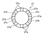
ロータ本体22Aの内筒部材27Aは、図21に示されるように、円筒状をなすとともに、図22に示されるように、その上端から下側(ステータ4A側)に向かって延びる複数の切欠部27aを有している。複数の切欠部27aは、周方向に等間隔で形成されている。また、内筒部材27Aは、取入口401に対応する位置に導入用開口部270を有し、排出口402に対応する位置に導出用開口部271を有している。
The
ロータ本体22Bの内筒部材27Bは、円筒状をなすとともに、図22に示されるように、その下端から上側(ステータ4A側)に向かって延びる複数の切欠部27aを有している。複数の切欠部27aは、周方向に等間隔で形成されている。また、内筒部材27Bは、取入口401に対応する位置に導入用開口部270を有し、排出口402に対応する位置に導出用開口部271を有している。
The
ロータ本体22Aのクランプ部材32Aは、図20(a)に示されるように、一対のアーム部33aと、一対のアーム部33aを連結する連結部33bと、上側のアーム部33aの先端に設けられた鉤部33cとを備えている。クランプ部材32Aは、下側のアーム部33aの先端部が内筒部材27Aにおける切欠部27aの先端部に当接し、かつ、上側のアーム部33aの鉤部33cが切欠部27aから上側へ突出した状態で、切欠部27aに支持される。
As shown in FIG. 20A, the
ロータ本体22Bのクランプ部材32Bは、図20(b)に示されるように、一対のアーム部33aと、一対のアーム部33aを連結する連結部33bと、下側のアーム部33aの先端に設けられた鉤部33cとを備えている。クランプ部材32Bは、上側のアーム部33aの先端部が内筒部材27Bにおける切欠部27aの先端部に当接し、かつ、下側のアーム部33aの鉤部33cが切欠部27aから下側へ突出した状態で、切欠部27aに支持される。
As shown in FIG. 20B, the
クラッチケース70bの外周面に形成された図外の雄ねじ部にナット部材34Aが螺合、装着されることにより、クランプ部材32Aが内筒部材27Aに固定され、これにより、ロータ本体22Aがクランプ部材32Aにより軸方向に挟み込まれた状態でクラッチケース70bに嵌合されている。
When the
同様に、クラッチケース70bの外周面に形成された雄ねじ部にナット部材34Aが螺合、装着されることにより、クランプ部材32Bが内筒部材27Bに固定され、これにより、ロータ本体22Bがクランプ部材32Bにより軸方向に挟み込まれた状態でクラッチケース70bに嵌合されている。
Similarly, when the
図21,22に示されるように、ロータ回転軸20Aの内部には、2本の導入通路44Aと、2本の導出通路45Aとが設けられており、これらはロータ回転軸20A内で並列に配置されている。各導入通路44Aは、導入用開口部270および取入口401を介して各ロータ本体22A,22Bの冷却液流通空間41に連通し、各導出通路45Aは、導出用開口部271および排出口402を介して各ロータ本体22A,22Bの冷却液流通空間41に連通している。
As shown in FIGS. 21 and 22, two
具体的には、図18に示されるように、クラッチケース70bの上側の端壁部702および周壁部701の内部に、各導入通路44Aと各ロータ本体22A,22Bの冷却液流通空間41とを連通させる導入側中継通路703が形成されるとともに、各導出通路45Aと各ロータ本体22A,22Bの冷却液流通空間41とを連通させる導出側中継通路704が形成されている。
Specifically, as shown in FIG. 18, the
2つのロータ本体22A,22Bの冷却液流通空間41は、導入側中継通路703および導出側中継通路704を介して並列に接続されており、導入側中継通路703に対し、ロータ本体22Aはロータ本体22Bよりも上流側に配置されている。そして、ロータ本体22Aとロータ本体22Bとは、導入側中継通路703との接続部の流路面積が互いに異なっている。具体的には、ロータ本体22Bにおける取入口401の流路面積が、ロータ本体22Aにおける取入口401の流路面積よりも大きく設定されるとともに、ロータ本体22Bにおける導入用開口部270の流路面積が、ロータ本体22Aにおける導入用開口部270の流路面積よりも大きく設定されている。
The
第2実施形態によれば、いわゆるダブルロータ構造のアキシャルギャップ型回転電機1Bにおいて、両ロータを効率よく冷却することができる。また、一方のロータ本体22Aと他方のロータ本体22Bとで、導入側中継通路703との接続位置が異なっているが、その接続部の流路面積を相違させることで、一方のロータ本体22Aと他方のロータ本体22Bとで冷却液流通空間41に流入する冷却液の流量を等しくすることができる。詳しく説明すると、一方のロータ本体22Aが他方のロータ本体22Bよりも導入側中継通路403における上流側に接続されている場合に、接続位置の違いで接続部同士の間に圧力損失による圧力差が生じて、流量に差が生じる可能性があるが、接続部の流路面積を相違させることで、その圧力差を流路面積の差で補って流量を等しくすることが可能となり、その結果、上流側のロータ本体22Aと下流側のロータ本体22Bとで、永久磁石26に対する冷却能力を同じにすることができる。
According to the second embodiment, in the axial gap type rotating
なお、上記第2実施形態は、クラッチ装置70を備えた構造の2ロータ1ステータ型の回転電機としたが、クラッチ装置70を備えない構造の2ロータ1ステータ型の回転電機としてもよい。
In the second embodiment, the two-rotor one-stator type rotary electric machine having the structure including the
また、上記各実施形態では、周方向に隣接する永久磁石26の間に隙間を設けているが、この隙間に、その隙間を塞ぐように軟磁性体54を配置してもよい(図23,24参照)。そして、クランプ部材50の永久磁石26側のアーム部501は、永久磁石26および軟磁性体54を、その境界部分の位置で押さえ込む構造としてもよい。具体的には、図24(a),(b)に示されるように、永久磁石26側のアーム部501を2本とし、この2本のアーム部501とジャケット部材40側のアーム部502とを、連結部503で連結した構造としてもよい。
In each of the above embodiments, a gap is provided between the
クランプ部材50をこのような構造とすることにより、永久磁石26および軟磁性体54をクランプ部材50でロータコア25側に押さえ込むことができる。さらに、アーム部501が非磁性体で構成される場合であっても、アーム部501が軟磁性体54全体を覆ってしまうことがなく、軟磁性体54に磁界が作用することによるリラクタンストルクの向上を図ることができる。
With the
また、図25に示されるように、永久磁石26Aは、ロータコア25の径方向に複数に分割されてもよい。図25に示される例では、永久磁石26Aは、周方向に延びるとともに径方向に並ぶように形成された複数の分割線51を有している。
As shown in FIG. 25, the
このように永久磁石26を複数に分割することで、永久磁石26の発熱の主要因である渦電流損を低減することができ、さらに、図24に示されるクランプ部材50のアーム部501で各永久磁石26を確実に保持することができる。
In this way, by dividing the
完全に分割された構造以外に、永久磁石の一体性を保ちながら、ステータ側が見かけ上分割された構造であってもよい。すなわち、図26に示されるように、永久磁石26Bは、ロータコア25の径方向に延びる複数の分割溝52および周方向に延びる複数の分割溝51を有しており、各分割溝51,52の溝底は、永久磁石26Bの軸方向(厚み方向)の中央部よりもロータコア25側に位置するようにしてもよい。
In addition to a completely divided structure, a structure in which the stator side is apparently divided while maintaining the integrity of the permanent magnet may be used. That is, as shown in FIG. 26, the
分割溝51,52の溝底が、軸方向における永久磁石26Bの中央部よりもロータコア25側に位置することで、永久磁石26Bがバラバラになることを防止してロータコア25への永久磁石26Bの組み付け作業の効率化を図りつつ、渦電流損を低減することができる。
Since the groove bottoms of the
各分割溝51,52には、樹脂や接着剤を含浸するようにしてもよく、その場合、永久磁石26Bの強度を確保することができる。
Each of the divided
1A,1B アキシャルギャップ型回転電機
2,2A ロータ
4,4A ステータ
20,20A 回転軸
22,22A,22B ロータ本体
25 ロータコア
26,26A,26B 永久磁石
32,32A,32B,50 クランプ部材
33a,501,502 アーム部
33b,503 連結部
40 ジャケット部材
40b 基板部
40c 内周壁
40d 外周壁
41 冷却液流通空間
44,44A 導入通路
45,45A 導出通路
48a 第1仕切壁
48b 第2仕切壁
51,52 分割溝
403 導入側中継通路
1A, 1B Axial Gap Type Rotating
Claims (13)
前記ロータ本体は、円盤状のロータコアと、このロータコアにおける前記ステータ側の第1面に周方向に並んだ状態で固定される複数の永久磁石と、前記ロータコアにおける前記ステータとは反対側の第2面全体を覆い、かつ、前記第2面との間に冷却液流通空間を形成するジャケット部材と、前記ジャケット部材を前記ロータコアに固定する固定手段とを備え、
前記回転軸は、前記冷却液流通空間に連通する冷却液の導入通路および導出通路を内部に備えていることを特徴とする、アキシャルギャップ型回転電機のロータ構造。 A rotor structure of an axial gap type rotating electrical machine comprising: a rotor having a rotating shaft and a rotor body rotating together with the rotating shaft; and a stator disposed in the axial direction of the rotating shaft so as to face the rotor body,
The rotor body includes a disk-shaped rotor core, a plurality of permanent magnets fixed in a circumferential direction on a first surface of the rotor core on the stator side, and a second of the rotor core opposite to the stator. A jacket member that covers the entire surface and that forms a coolant circulation space between the second surface and a fixing means that fixes the jacket member to the rotor core;
The rotor structure of an axial gap type rotating electrical machine, wherein the rotary shaft includes therein a coolant introduction passage and a lead-out passage communicating with the coolant circulation space.
前記冷却液流通空間は、前記内周壁と前記外周壁との間で周方向に連続して形成されていることを特徴とする、請求項1に記載のアキシャルギャップ型回転電機のロータ構造。 The jacket member is provided on a substrate portion that faces the rotor core and forms the coolant circulation space between the rotor core, an inner peripheral wall provided in a central portion of the substrate portion, and an outer peripheral portion of the substrate portion. An outer peripheral wall,
The rotor structure of an axial gap type rotating electrical machine according to claim 1, wherein the coolant circulation space is continuously formed in the circumferential direction between the inner peripheral wall and the outer peripheral wall.
前記第1仕切壁は、前記内周壁から径方向外側へ延び、かつ、前記外周壁との間に隙間を有し、
前記第2仕切壁は、前記外周壁から径方向内側へ延び、かつ、前記内周壁との間に隙間を有し、
前記第1仕切壁と前記第2仕切壁とが、周方向に交互に配置されていることを特徴とする、請求項2に記載のアキシャルギャップ型回転電機のロータ構造。 The jacket member has a first partition wall and a second partition wall that partition the coolant circulation space into a plurality of sections in the circumferential direction,
The first partition wall extends radially outward from the inner peripheral wall, and has a gap with the outer peripheral wall,
The second partition wall extends radially inward from the outer peripheral wall, and has a gap with the inner peripheral wall;
The rotor structure of an axial gap type rotating electrical machine according to claim 2, wherein the first partition wall and the second partition wall are alternately arranged in a circumferential direction.
前記クランプ部材の前記永久磁石側のアーム部は、前記永久磁石および前記軟磁性体を、その境界部分の位置で押さえ込むことを特徴とする、請求項4または5に記載のアキシャルギャップ型回転電機のロータ構造。 In the gap between the permanent magnets adjacent to each other in the circumferential direction, a soft magnetic material is disposed in a state of closing the gap,
6. The axial gap type rotating electric machine according to claim 4, wherein the arm portion on the permanent magnet side of the clamp member presses the permanent magnet and the soft magnetic body at a boundary portion thereof. Rotor structure.
前記2つの取入口は、前記径方向の互いに反対側に配置され、前記2つの排出口は、前記径方向の互いに反対側に配置されていることを特徴とする、請求項2乃至9のいずれかに記載のアキシャルギャップ型回転電機のロータ構造。 The jacket member has two intake ports for taking in the coolant from the introduction passage into the coolant circulation space and two discharge ports for discharging the coolant from the coolant circulation space to the outlet passage. Prepared,
The two intake ports are arranged on opposite sides in the radial direction, and the two discharge ports are arranged on opposite sides in the radial direction. A rotor structure of an axial gap type rotating electrical machine according to claim 1.
前記導入通路と前記導出通路とは、前記回転軸内で並列に配置され、
前記導入通路および前記導出通路は、各前記ロータの前記冷却液流通空間に連通していることを特徴とする、請求項1乃至11のいずれかに記載のアキシャルギャップ型回転電機のロータ構造。 The axial gap type rotating electrical machine has a structure in which two rotors are arranged on both sides of one stator in the axial direction,
The introduction passage and the lead-out passage are arranged in parallel in the rotation shaft,
The rotor structure of an axial gap type rotating electrical machine according to any one of claims 1 to 11, wherein the introduction passage and the lead-out passage communicate with the coolant circulation space of each rotor.
一方のロータと他方のロータとは、前記導入通路または前記導入側中継通路との接続部の流路面積が互いに異なることを特徴とする、請求項12に記載のアキシャルギャップ型回転電機のロータ構造。
The coolant circulation space of the two rotors is connected in parallel via the introduction passage and the lead-out passage, or the lead-out side relay passage connected to the lead-in passage and the lead-out side connected to the lead-out passage Connected in parallel via a relay passage,
The rotor structure of an axial gap type rotating electrical machine according to claim 12, wherein the one rotor and the other rotor have different flow passage areas at the connection portion between the introduction passage or the introduction-side relay passage. .
Priority Applications (1)
| Application Number | Priority Date | Filing Date | Title |
|---|---|---|---|
| JP2015120159A JP2017005940A (en) | 2015-06-15 | 2015-06-15 | Rotor structure of axial gap type rotary electric machine |
Applications Claiming Priority (1)
| Application Number | Priority Date | Filing Date | Title |
|---|---|---|---|
| JP2015120159A JP2017005940A (en) | 2015-06-15 | 2015-06-15 | Rotor structure of axial gap type rotary electric machine |
Publications (1)
| Publication Number | Publication Date |
|---|---|
| JP2017005940A true JP2017005940A (en) | 2017-01-05 |
Family
ID=57754554
Family Applications (1)
| Application Number | Title | Priority Date | Filing Date |
|---|---|---|---|
| JP2015120159A Abandoned JP2017005940A (en) | 2015-06-15 | 2015-06-15 | Rotor structure of axial gap type rotary electric machine |
Country Status (1)
| Country | Link |
|---|---|
| JP (1) | JP2017005940A (en) |
Cited By (3)
| Publication number | Priority date | Publication date | Assignee | Title |
|---|---|---|---|---|
| CN107910966A (en) * | 2017-12-21 | 2018-04-13 | 宁波普尔机电制造有限公司 | Brushless direct current motor inner rotor core |
| IT201900015045A1 (en) * | 2019-08-26 | 2021-02-26 | Texa Dynamics S R L | "Electric motor with cooling circuit" |
| CN113691044A (en) * | 2021-07-05 | 2021-11-23 | 湖北工业大学 | Novel axial coreless motor rotor structure and heat dissipation method thereof |
-
2015
- 2015-06-15 JP JP2015120159A patent/JP2017005940A/en not_active Abandoned
Cited By (4)
| Publication number | Priority date | Publication date | Assignee | Title |
|---|---|---|---|---|
| CN107910966A (en) * | 2017-12-21 | 2018-04-13 | 宁波普尔机电制造有限公司 | Brushless direct current motor inner rotor core |
| IT201900015045A1 (en) * | 2019-08-26 | 2021-02-26 | Texa Dynamics S R L | "Electric motor with cooling circuit" |
| WO2021038451A1 (en) * | 2019-08-26 | 2021-03-04 | Texa Dynamics S.R.L. | Electric motor |
| CN113691044A (en) * | 2021-07-05 | 2021-11-23 | 湖北工业大学 | Novel axial coreless motor rotor structure and heat dissipation method thereof |
Similar Documents
| Publication | Publication Date | Title |
|---|---|---|
| KR101475369B1 (en) | Rotary machine | |
| CA2995609C (en) | Cast cooling arrangement for electric machines | |
| JP6270213B2 (en) | Electric motor | |
| JP2012105487A (en) | Cooling device for electric motor | |
| JP7055668B2 (en) | Rotating machine rotor | |
| JP2017099181A (en) | Axial-gap dynamo-electric machine | |
| JP6210002B2 (en) | Axial gap type rotating electrical machine | |
| JP2016054608A (en) | Rotor for rotary electric machine | |
| JP6402739B2 (en) | Rotating electric machine | |
| JP2017005940A (en) | Rotor structure of axial gap type rotary electric machine | |
| JP2015211573A (en) | Rotor, rotary electric machine and compressor | |
| JP5699824B2 (en) | Electric motor | |
| JP6852817B2 (en) | Rotating machine | |
| JP2009232535A (en) | Rotator of rotating electrical machine | |
| JP2020137269A (en) | Rotary electric machine | |
| JP2011101461A (en) | Electric motor | |
| JP6365516B2 (en) | Stator and axial gap type rotating electric machine including the stator | |
| JP6151668B2 (en) | Rotor for rotating electrical machines | |
| JP5710886B2 (en) | Rotating electric machine | |
| JP6137019B2 (en) | Axial gap type rotating electrical machine | |
| KR20170086903A (en) | Motor apparatus and stator core thereof | |
| JP2006174550A (en) | Stator structure of disk-type rotating electric machine | |
| JP7411825B2 (en) | rotating electric machine | |
| US20230063496A1 (en) | Electric motor | |
| JP7331623B2 (en) | Rotating electric machine and stator end plate |
Legal Events
| Date | Code | Title | Description |
|---|---|---|---|
| A621 | Written request for application examination |
Free format text: JAPANESE INTERMEDIATE CODE: A621 Effective date: 20170323 |
|
| A977 | Report on retrieval |
Free format text: JAPANESE INTERMEDIATE CODE: A971007 Effective date: 20171214 |
|
| A131 | Notification of reasons for refusal |
Free format text: JAPANESE INTERMEDIATE CODE: A131 Effective date: 20171220 |
|
| A762 | Written abandonment of application |
Free format text: JAPANESE INTERMEDIATE CODE: A762 Effective date: 20171226 |