WO2014115762A1 - Sizing-agent-coated carbon fibre bundle, carbon-fibre-bundle production method, and prepreg - Google Patents
Sizing-agent-coated carbon fibre bundle, carbon-fibre-bundle production method, and prepreg Download PDFInfo
- Publication number
- WO2014115762A1 WO2014115762A1 PCT/JP2014/051248 JP2014051248W WO2014115762A1 WO 2014115762 A1 WO2014115762 A1 WO 2014115762A1 JP 2014051248 W JP2014051248 W JP 2014051248W WO 2014115762 A1 WO2014115762 A1 WO 2014115762A1
- Authority
- WO
- WIPO (PCT)
- Prior art keywords
- carbon fiber
- fiber bundle
- sizing agent
- fiber
- bundle
- Prior art date
Links
- 239000000835 fiber Substances 0.000 title claims abstract description 507
- 239000003795 chemical substances by application Substances 0.000 title claims abstract description 245
- 229910052799 carbon Inorganic materials 0.000 title claims abstract description 14
- OKTJSMMVPCPJKN-UHFFFAOYSA-N Carbon Chemical compound [C] OKTJSMMVPCPJKN-UHFFFAOYSA-N 0.000 title claims abstract description 12
- 238000004519 manufacturing process Methods 0.000 title claims description 38
- 238000004513 sizing Methods 0.000 claims abstract description 234
- 239000004593 Epoxy Substances 0.000 claims abstract description 213
- 150000001875 compounds Chemical class 0.000 claims abstract description 206
- 238000000034 method Methods 0.000 claims abstract description 141
- 239000002131 composite material Substances 0.000 claims abstract description 55
- 125000001931 aliphatic group Chemical group 0.000 claims abstract description 45
- 125000003118 aryl group Chemical group 0.000 claims abstract description 38
- 238000013467 fragmentation Methods 0.000 claims abstract description 35
- 238000006062 fragmentation reaction Methods 0.000 claims abstract description 35
- 150000004982 aromatic amines Chemical class 0.000 claims abstract description 10
- 239000011248 coating agent Substances 0.000 claims abstract description 3
- 238000000576 coating method Methods 0.000 claims abstract description 3
- 229920000049 Carbon (fiber) Polymers 0.000 claims description 499
- 239000004917 carbon fiber Substances 0.000 claims description 499
- VNWKTOKETHGBQD-UHFFFAOYSA-N methane Chemical compound C VNWKTOKETHGBQD-UHFFFAOYSA-N 0.000 claims description 469
- 238000003763 carbonization Methods 0.000 claims description 76
- 229920005989 resin Polymers 0.000 claims description 73
- 239000011347 resin Substances 0.000 claims description 73
- 229920002239 polyacrylonitrile Polymers 0.000 claims description 68
- 239000002243 precursor Substances 0.000 claims description 40
- 238000004833 X-ray photoelectron spectroscopy Methods 0.000 claims description 15
- 238000001228 spectrum Methods 0.000 claims description 6
- 229920001187 thermosetting polymer Polymers 0.000 claims description 6
- 238000009656 pre-carbonization Methods 0.000 claims description 5
- 239000012298 atmosphere Substances 0.000 claims description 4
- 239000000463 material Substances 0.000 abstract description 9
- 230000001747 exhibiting effect Effects 0.000 abstract description 4
- 239000012530 fluid Substances 0.000 description 51
- 238000012360 testing method Methods 0.000 description 51
- 125000003700 epoxy group Chemical group 0.000 description 46
- 239000011159 matrix material Substances 0.000 description 46
- 230000008569 process Effects 0.000 description 41
- IISBACLAFKSPIT-UHFFFAOYSA-N bisphenol A Chemical class C=1C=C(O)C=CC=1C(C)(C)C1=CC=C(O)C=C1 IISBACLAFKSPIT-UHFFFAOYSA-N 0.000 description 40
- XLYOFNOQVPJJNP-UHFFFAOYSA-N water Chemical compound O XLYOFNOQVPJJNP-UHFFFAOYSA-N 0.000 description 38
- 230000001965 increasing effect Effects 0.000 description 37
- 239000011208 reinforced composite material Substances 0.000 description 36
- 239000000243 solution Substances 0.000 description 34
- 230000001976 improved effect Effects 0.000 description 32
- 238000009987 spinning Methods 0.000 description 30
- 125000000524 functional group Chemical group 0.000 description 26
- 238000005259 measurement Methods 0.000 description 25
- 238000004381 surface treatment Methods 0.000 description 25
- IAZDPXIOMUYVGZ-UHFFFAOYSA-N Dimethylsulphoxide Chemical compound CS(C)=O IAZDPXIOMUYVGZ-UHFFFAOYSA-N 0.000 description 24
- 239000000126 substance Substances 0.000 description 24
- 230000007423 decrease Effects 0.000 description 23
- 229920005992 thermoplastic resin Polymers 0.000 description 23
- QVGXLLKOCUKJST-UHFFFAOYSA-N atomic oxygen Chemical compound [O] QVGXLLKOCUKJST-UHFFFAOYSA-N 0.000 description 21
- 230000000052 comparative effect Effects 0.000 description 21
- 229910052760 oxygen Inorganic materials 0.000 description 21
- 239000001301 oxygen Substances 0.000 description 21
- 238000009826 distribution Methods 0.000 description 19
- 238000010438 heat treatment Methods 0.000 description 18
- 239000002904 solvent Substances 0.000 description 18
- 239000007864 aqueous solution Substances 0.000 description 17
- 238000006243 chemical reaction Methods 0.000 description 17
- 239000003822 epoxy resin Substances 0.000 description 17
- 239000000203 mixture Substances 0.000 description 17
- 229920000647 polyepoxide Polymers 0.000 description 17
- GYZLOYUZLJXAJU-UHFFFAOYSA-N diglycidyl ether Chemical compound C1OC1COCC1CO1 GYZLOYUZLJXAJU-UHFFFAOYSA-N 0.000 description 16
- 238000001723 curing Methods 0.000 description 15
- 239000008151 electrolyte solution Substances 0.000 description 15
- 125000002887 hydroxy group Chemical group [H]O* 0.000 description 15
- OFOBLEOULBTSOW-UHFFFAOYSA-N Malonic acid Chemical compound OC(=O)CC(O)=O OFOBLEOULBTSOW-UHFFFAOYSA-N 0.000 description 14
- 239000000047 product Substances 0.000 description 14
- CXMXRPHRNRROMY-UHFFFAOYSA-N sebacic acid Chemical compound OC(=O)CCCCCCCCC(O)=O CXMXRPHRNRROMY-UHFFFAOYSA-N 0.000 description 14
- JAHNSTQSQJOJLO-UHFFFAOYSA-N 2-(3-fluorophenyl)-1h-imidazole Chemical compound FC1=CC=CC(C=2NC=CN=2)=C1 JAHNSTQSQJOJLO-UHFFFAOYSA-N 0.000 description 13
- LYCAIKOWRPUZTN-UHFFFAOYSA-N Ethylene glycol Chemical compound OCCO LYCAIKOWRPUZTN-UHFFFAOYSA-N 0.000 description 13
- PXKLMJQFEQBVLD-UHFFFAOYSA-N bisphenol F Chemical class C1=CC(O)=CC=C1CC1=CC=C(O)C=C1 PXKLMJQFEQBVLD-UHFFFAOYSA-N 0.000 description 13
- LVHBHZANLOWSRM-UHFFFAOYSA-N methylenebutanedioic acid Natural products OC(=O)CC(=C)C(O)=O LVHBHZANLOWSRM-UHFFFAOYSA-N 0.000 description 13
- OZAIFHULBGXAKX-UHFFFAOYSA-N 2-(2-cyanopropan-2-yldiazenyl)-2-methylpropanenitrile Chemical compound N#CC(C)(C)N=NC(C)(C)C#N OZAIFHULBGXAKX-UHFFFAOYSA-N 0.000 description 12
- -1 interface Substances 0.000 description 12
- 230000003647 oxidation Effects 0.000 description 12
- 238000007254 oxidation reaction Methods 0.000 description 12
- 230000000704 physical effect Effects 0.000 description 12
- 229920000642 polymer Polymers 0.000 description 12
- 230000015271 coagulation Effects 0.000 description 11
- 238000005345 coagulation Methods 0.000 description 11
- 239000012299 nitrogen atmosphere Substances 0.000 description 11
- QAOWNCQODCNURD-UHFFFAOYSA-N Sulfuric acid Chemical compound OS(O)(=O)=O QAOWNCQODCNURD-UHFFFAOYSA-N 0.000 description 10
- VZCYOOQTPOCHFL-UPHRSURJSA-N maleic acid Chemical compound OC(=O)\C=C/C(O)=O VZCYOOQTPOCHFL-UPHRSURJSA-N 0.000 description 10
- 239000011976 maleic acid Substances 0.000 description 10
- 239000000178 monomer Substances 0.000 description 10
- AFEQENGXSMURHA-UHFFFAOYSA-N oxiran-2-ylmethanamine Chemical compound NCC1CO1 AFEQENGXSMURHA-UHFFFAOYSA-N 0.000 description 10
- VZCYOOQTPOCHFL-UHFFFAOYSA-N trans-butenedioic acid Natural products OC(=O)C=CC(O)=O VZCYOOQTPOCHFL-UHFFFAOYSA-N 0.000 description 10
- WEVYAHXRMPXWCK-UHFFFAOYSA-N Acetonitrile Chemical compound CC#N WEVYAHXRMPXWCK-UHFFFAOYSA-N 0.000 description 9
- BRLQWZUYTZBJKN-UHFFFAOYSA-N Epichlorohydrin Chemical compound ClCC1CO1 BRLQWZUYTZBJKN-UHFFFAOYSA-N 0.000 description 9
- PEDCQBHIVMGVHV-UHFFFAOYSA-N Glycerine Chemical compound OCC(O)CO PEDCQBHIVMGVHV-UHFFFAOYSA-N 0.000 description 9
- ZMXDDKWLCZADIW-UHFFFAOYSA-N N,N-Dimethylformamide Chemical compound CN(C)C=O ZMXDDKWLCZADIW-UHFFFAOYSA-N 0.000 description 9
- 239000002585 base Substances 0.000 description 9
- 239000003999 initiator Substances 0.000 description 9
- 229920001296 polysiloxane Polymers 0.000 description 9
- 239000011342 resin composition Substances 0.000 description 9
- QGZKDVFQNNGYKY-UHFFFAOYSA-N Ammonia Chemical compound N QGZKDVFQNNGYKY-UHFFFAOYSA-N 0.000 description 8
- ATRRKUHOCOJYRX-UHFFFAOYSA-N Ammonium bicarbonate Chemical compound [NH4+].OC([O-])=O ATRRKUHOCOJYRX-UHFFFAOYSA-N 0.000 description 8
- 239000000853 adhesive Substances 0.000 description 8
- 230000001070 adhesive effect Effects 0.000 description 8
- 125000003368 amide group Chemical group 0.000 description 8
- 239000001099 ammonium carbonate Substances 0.000 description 8
- 230000005540 biological transmission Effects 0.000 description 8
- 125000003178 carboxy group Chemical group [H]OC(*)=O 0.000 description 8
- 238000012937 correction Methods 0.000 description 8
- 238000001035 drying Methods 0.000 description 8
- 230000005484 gravity Effects 0.000 description 8
- 229920003986 novolac Polymers 0.000 description 8
- NLHHRLWOUZZQLW-UHFFFAOYSA-N Acrylonitrile Chemical group C=CC#N NLHHRLWOUZZQLW-UHFFFAOYSA-N 0.000 description 7
- 238000007664 blowing Methods 0.000 description 7
- 238000011156 evaluation Methods 0.000 description 7
- 238000010528 free radical solution polymerization reaction Methods 0.000 description 7
- 239000007791 liquid phase Substances 0.000 description 7
- 229920002545 silicone oil Polymers 0.000 description 7
- CSCPPACGZOOCGX-UHFFFAOYSA-N Acetone Chemical compound CC(C)=O CSCPPACGZOOCGX-UHFFFAOYSA-N 0.000 description 6
- 229910000013 Ammonium bicarbonate Inorganic materials 0.000 description 6
- IJGRMHOSHXDMSA-UHFFFAOYSA-N Atomic nitrogen Chemical compound N#N IJGRMHOSHXDMSA-UHFFFAOYSA-N 0.000 description 6
- 229930185605 Bisphenol Natural products 0.000 description 6
- ISWSIDIOOBJBQZ-UHFFFAOYSA-N Phenol Chemical compound OC1=CC=CC=C1 ISWSIDIOOBJBQZ-UHFFFAOYSA-N 0.000 description 6
- DNIAPMSPPWPWGF-UHFFFAOYSA-N Propylene glycol Chemical compound CC(O)CO DNIAPMSPPWPWGF-UHFFFAOYSA-N 0.000 description 6
- 235000012538 ammonium bicarbonate Nutrition 0.000 description 6
- 238000007796 conventional method Methods 0.000 description 6
- 229920001577 copolymer Polymers 0.000 description 6
- 238000000280 densification Methods 0.000 description 6
- MTHSVFCYNBDYFN-UHFFFAOYSA-N diethylene glycol Chemical compound OCCOCCO MTHSVFCYNBDYFN-UHFFFAOYSA-N 0.000 description 6
- RTZKZFJDLAIYFH-UHFFFAOYSA-N ether Substances CCOCC RTZKZFJDLAIYFH-UHFFFAOYSA-N 0.000 description 6
- 230000009477 glass transition Effects 0.000 description 6
- 125000004435 hydrogen atom Chemical group [H]* 0.000 description 6
- 230000003993 interaction Effects 0.000 description 6
- IGALFTFNPPBUDN-UHFFFAOYSA-N phenyl-[2,3,4,5-tetrakis(oxiran-2-ylmethyl)phenyl]methanediamine Chemical compound C=1C(CC2OC2)=C(CC2OC2)C(CC2OC2)=C(CC2OC2)C=1C(N)(N)C1=CC=CC=C1 IGALFTFNPPBUDN-UHFFFAOYSA-N 0.000 description 6
- 229920006393 polyether sulfone Polymers 0.000 description 6
- XSQUKJJJFZCRTK-UHFFFAOYSA-N urea group Chemical group NC(=O)N XSQUKJJJFZCRTK-UHFFFAOYSA-N 0.000 description 6
- 238000005406 washing Methods 0.000 description 6
- HIXDQWDOVZUNNA-UHFFFAOYSA-N 2-(3,4-dimethoxyphenyl)-5-hydroxy-7-methoxychromen-4-one Chemical compound C=1C(OC)=CC(O)=C(C(C=2)=O)C=1OC=2C1=CC=C(OC)C(OC)=C1 HIXDQWDOVZUNNA-UHFFFAOYSA-N 0.000 description 5
- 229920003171 Poly (ethylene oxide) Polymers 0.000 description 5
- 229910000831 Steel Inorganic materials 0.000 description 5
- 150000001412 amines Chemical class 0.000 description 5
- 230000005611 electricity Effects 0.000 description 5
- 239000003792 electrolyte Substances 0.000 description 5
- 238000010828 elution Methods 0.000 description 5
- 239000001257 hydrogen Substances 0.000 description 5
- 229910052739 hydrogen Inorganic materials 0.000 description 5
- 239000010959 steel Substances 0.000 description 5
- 125000000472 sulfonyl group Chemical group *S(*)(=O)=O 0.000 description 5
- PUPZLCDOIYMWBV-UHFFFAOYSA-N (+/-)-1,3-Butanediol Chemical compound CC(O)CCO PUPZLCDOIYMWBV-UHFFFAOYSA-N 0.000 description 4
- PULOARGYCVHSDH-UHFFFAOYSA-N 2-amino-3,4,5-tris(oxiran-2-ylmethyl)phenol Chemical compound C1OC1CC1=C(CC2OC2)C(N)=C(O)C=C1CC1CO1 PULOARGYCVHSDH-UHFFFAOYSA-N 0.000 description 4
- QTWJRLJHJPIABL-UHFFFAOYSA-N 2-methylphenol;3-methylphenol;4-methylphenol Chemical compound CC1=CC=C(O)C=C1.CC1=CC=CC(O)=C1.CC1=CC=CC=C1O QTWJRLJHJPIABL-UHFFFAOYSA-N 0.000 description 4
- HEDRZPFGACZZDS-UHFFFAOYSA-N Chloroform Chemical compound ClC(Cl)Cl HEDRZPFGACZZDS-UHFFFAOYSA-N 0.000 description 4
- RYGMFSIKBFXOCR-UHFFFAOYSA-N Copper Chemical compound [Cu] RYGMFSIKBFXOCR-UHFFFAOYSA-N 0.000 description 4
- MQJKPEGWNLWLTK-UHFFFAOYSA-N Dapsone Chemical compound C1=CC(N)=CC=C1S(=O)(=O)C1=CC=C(N)C=C1 MQJKPEGWNLWLTK-UHFFFAOYSA-N 0.000 description 4
- 239000004952 Polyamide Substances 0.000 description 4
- 229920004738 ULTEM® Polymers 0.000 description 4
- 239000002390 adhesive tape Substances 0.000 description 4
- QGZKDVFQNNGYKY-UHFFFAOYSA-O ammonium group Chemical group [NH4+] QGZKDVFQNNGYKY-UHFFFAOYSA-O 0.000 description 4
- 238000004458 analytical method Methods 0.000 description 4
- 230000015572 biosynthetic process Effects 0.000 description 4
- WERYXYBDKMZEQL-UHFFFAOYSA-N butane-1,4-diol Chemical compound OCCCCO WERYXYBDKMZEQL-UHFFFAOYSA-N 0.000 description 4
- 238000004581 coalescence Methods 0.000 description 4
- 229910052802 copper Inorganic materials 0.000 description 4
- 239000010949 copper Substances 0.000 description 4
- 229930003836 cresol Natural products 0.000 description 4
- 230000003247 decreasing effect Effects 0.000 description 4
- 230000007547 defect Effects 0.000 description 4
- ZUOUZKKEUPVFJK-UHFFFAOYSA-N diphenyl Chemical group C1=CC=CC=C1C1=CC=CC=C1 ZUOUZKKEUPVFJK-UHFFFAOYSA-N 0.000 description 4
- 239000003995 emulsifying agent Substances 0.000 description 4
- 238000005755 formation reaction Methods 0.000 description 4
- 238000001891 gel spinning Methods 0.000 description 4
- 239000012948 isocyanate Substances 0.000 description 4
- 150000002513 isocyanates Chemical class 0.000 description 4
- 230000033001 locomotion Effects 0.000 description 4
- 229910052757 nitrogen Inorganic materials 0.000 description 4
- 229920002492 poly(sulfone) Polymers 0.000 description 4
- 229920002647 polyamide Polymers 0.000 description 4
- 238000006116 polymerization reaction Methods 0.000 description 4
- 229920005862 polyol Polymers 0.000 description 4
- 150000003077 polyols Chemical class 0.000 description 4
- 238000012545 processing Methods 0.000 description 4
- YPFDHNVEDLHUCE-UHFFFAOYSA-N propane-1,3-diol Chemical compound OCCCO YPFDHNVEDLHUCE-UHFFFAOYSA-N 0.000 description 4
- GHMLBKRAJCXXBS-UHFFFAOYSA-N resorcinol Chemical compound OC1=CC=CC(O)=C1 GHMLBKRAJCXXBS-UHFFFAOYSA-N 0.000 description 4
- 230000035945 sensitivity Effects 0.000 description 4
- 125000006850 spacer group Chemical group 0.000 description 4
- 238000009864 tensile test Methods 0.000 description 4
- JOYRKODLDBILNP-UHFFFAOYSA-N urethane group Chemical group NC(=O)OCC JOYRKODLDBILNP-UHFFFAOYSA-N 0.000 description 4
- 229920002554 vinyl polymer Polymers 0.000 description 4
- HECLRDQVFMWTQS-RGOKHQFPSA-N 1755-01-7 Chemical group C1[C@H]2[C@@H]3CC=C[C@@H]3[C@@H]1C=C2 HECLRDQVFMWTQS-RGOKHQFPSA-N 0.000 description 3
- CJWNFAKWHDOUKL-UHFFFAOYSA-N 2-(2-phenylpropan-2-yl)phenol Chemical compound C=1C=CC=C(O)C=1C(C)(C)C1=CC=CC=C1 CJWNFAKWHDOUKL-UHFFFAOYSA-N 0.000 description 3
- ZWEHNKRNPOVVGH-UHFFFAOYSA-N 2-Butanone Chemical compound CCC(C)=O ZWEHNKRNPOVVGH-UHFFFAOYSA-N 0.000 description 3
- VPWNQTHUCYMVMZ-UHFFFAOYSA-N 4,4'-sulfonyldiphenol Chemical compound C1=CC(O)=CC=C1S(=O)(=O)C1=CC=C(O)C=C1 VPWNQTHUCYMVMZ-UHFFFAOYSA-N 0.000 description 3
- FVCSARBUZVPSQF-UHFFFAOYSA-N 5-(2,4-dioxooxolan-3-yl)-7-methyl-3a,4,5,7a-tetrahydro-2-benzofuran-1,3-dione Chemical compound C1C(C(OC2=O)=O)C2C(C)=CC1C1C(=O)COC1=O FVCSARBUZVPSQF-UHFFFAOYSA-N 0.000 description 3
- QTBSBXVTEAMEQO-UHFFFAOYSA-N Acetic acid Chemical compound CC(O)=O QTBSBXVTEAMEQO-UHFFFAOYSA-N 0.000 description 3
- 229920003319 Araldite® Polymers 0.000 description 3
- FBPFZTCFMRRESA-FSIIMWSLSA-N D-Glucitol Chemical class OC[C@H](O)[C@H](O)[C@@H](O)[C@H](O)CO FBPFZTCFMRRESA-FSIIMWSLSA-N 0.000 description 3
- FBPFZTCFMRRESA-JGWLITMVSA-N D-glucitol Chemical class OC[C@H](O)[C@@H](O)[C@H](O)[C@H](O)CO FBPFZTCFMRRESA-JGWLITMVSA-N 0.000 description 3
- OKKJLVBELUTLKV-UHFFFAOYSA-N Methanol Chemical compound OC OKKJLVBELUTLKV-UHFFFAOYSA-N 0.000 description 3
- GRYLNZFGIOXLOG-UHFFFAOYSA-N Nitric acid Chemical compound O[N+]([O-])=O GRYLNZFGIOXLOG-UHFFFAOYSA-N 0.000 description 3
- MUBZPKHOEPUJKR-UHFFFAOYSA-N Oxalic acid Chemical compound OC(=O)C(O)=O MUBZPKHOEPUJKR-UHFFFAOYSA-N 0.000 description 3
- 239000004695 Polyether sulfone Substances 0.000 description 3
- 239000004697 Polyetherimide Substances 0.000 description 3
- 239000004642 Polyimide Substances 0.000 description 3
- KWYUFKZDYYNOTN-UHFFFAOYSA-M Potassium hydroxide Chemical compound [OH-].[K+] KWYUFKZDYYNOTN-UHFFFAOYSA-M 0.000 description 3
- HEMHJVSKTPXQMS-UHFFFAOYSA-M Sodium hydroxide Chemical compound [OH-].[Na+] HEMHJVSKTPXQMS-UHFFFAOYSA-M 0.000 description 3
- 239000002253 acid Substances 0.000 description 3
- 230000008859 change Effects 0.000 description 3
- 230000006866 deterioration Effects 0.000 description 3
- 238000007598 dipping method Methods 0.000 description 3
- 238000000578 dry spinning Methods 0.000 description 3
- 239000000839 emulsion Substances 0.000 description 3
- 239000003733 fiber-reinforced composite Substances 0.000 description 3
- 239000007789 gas Substances 0.000 description 3
- 239000012943 hotmelt Substances 0.000 description 3
- RAXXELZNTBOGNW-UHFFFAOYSA-N imidazole Natural products C1=CNC=N1 RAXXELZNTBOGNW-UHFFFAOYSA-N 0.000 description 3
- 125000005462 imide group Chemical group 0.000 description 3
- 230000007774 longterm Effects 0.000 description 3
- 230000003472 neutralizing effect Effects 0.000 description 3
- 229910017604 nitric acid Inorganic materials 0.000 description 3
- 239000003921 oil Substances 0.000 description 3
- 235000019198 oils Nutrition 0.000 description 3
- 230000001590 oxidative effect Effects 0.000 description 3
- 239000002245 particle Substances 0.000 description 3
- 229920006287 phenoxy resin Polymers 0.000 description 3
- 239000013034 phenoxy resin Substances 0.000 description 3
- 229920003023 plastic Polymers 0.000 description 3
- 239000004033 plastic Substances 0.000 description 3
- 229920001601 polyetherimide Polymers 0.000 description 3
- 229920000223 polyglycerol Polymers 0.000 description 3
- 229920001721 polyimide Polymers 0.000 description 3
- 230000001737 promoting effect Effects 0.000 description 3
- 230000009257 reactivity Effects 0.000 description 3
- 229920006395 saturated elastomer Polymers 0.000 description 3
- 239000000600 sorbitol Chemical class 0.000 description 3
- 239000011550 stock solution Substances 0.000 description 3
- 125000000020 sulfo group Chemical group O=S(=O)([*])O[H] 0.000 description 3
- 239000013585 weight reducing agent Substances 0.000 description 3
- 238000002166 wet spinning Methods 0.000 description 3
- KGSFMPRFQVLGTJ-UHFFFAOYSA-N 1,1,2-triphenylethylbenzene Chemical compound C=1C=CC=CC=1C(C=1C=CC=CC=1)(C=1C=CC=CC=1)CC1=CC=CC=C1 KGSFMPRFQVLGTJ-UHFFFAOYSA-N 0.000 description 2
- 229940083957 1,2-butanediol Drugs 0.000 description 2
- AHDSRXYHVZECER-UHFFFAOYSA-N 2,4,6-tris[(dimethylamino)methyl]phenol Chemical compound CN(C)CC1=CC(CN(C)C)=C(O)C(CN(C)C)=C1 AHDSRXYHVZECER-UHFFFAOYSA-N 0.000 description 2
- SMZOUWXMTYCWNB-UHFFFAOYSA-N 2-(2-methoxy-5-methylphenyl)ethanamine Chemical compound COC1=CC=C(C)C=C1CCN SMZOUWXMTYCWNB-UHFFFAOYSA-N 0.000 description 2
- NIXOWILDQLNWCW-UHFFFAOYSA-N 2-Propenoic acid Natural products OC(=O)C=C NIXOWILDQLNWCW-UHFFFAOYSA-N 0.000 description 2
- FUIQBJHUESBZNU-UHFFFAOYSA-N 2-[(dimethylazaniumyl)methyl]phenolate Chemical compound CN(C)CC1=CC=CC=C1O FUIQBJHUESBZNU-UHFFFAOYSA-N 0.000 description 2
- LCZVSXRMYJUNFX-UHFFFAOYSA-N 2-[2-(2-hydroxypropoxy)propoxy]propan-1-ol Chemical compound CC(O)COC(C)COC(C)CO LCZVSXRMYJUNFX-UHFFFAOYSA-N 0.000 description 2
- OVEUFHOBGCSKSH-UHFFFAOYSA-N 2-methyl-n,n-bis(oxiran-2-ylmethyl)aniline Chemical compound CC1=CC=CC=C1N(CC1OC1)CC1OC1 OVEUFHOBGCSKSH-UHFFFAOYSA-N 0.000 description 2
- WDGCBNTXZHJTHJ-UHFFFAOYSA-N 2h-1,3-oxazol-2-id-4-one Chemical group O=C1CO[C-]=N1 WDGCBNTXZHJTHJ-UHFFFAOYSA-N 0.000 description 2
- CWLKGDAVCFYWJK-UHFFFAOYSA-N 3-aminophenol Chemical compound NC1=CC=CC(O)=C1 CWLKGDAVCFYWJK-UHFFFAOYSA-N 0.000 description 2
- HLBLWEWZXPIGSM-UHFFFAOYSA-N 4-Aminophenyl ether Chemical compound C1=CC(N)=CC=C1OC1=CC=C(N)C=C1 HLBLWEWZXPIGSM-UHFFFAOYSA-N 0.000 description 2
- PLIKAWJENQZMHA-UHFFFAOYSA-N 4-aminophenol Chemical compound NC1=CC=C(O)C=C1 PLIKAWJENQZMHA-UHFFFAOYSA-N 0.000 description 2
- 229920002972 Acrylic fiber Polymers 0.000 description 2
- 239000004925 Acrylic resin Substances 0.000 description 2
- 229920000178 Acrylic resin Polymers 0.000 description 2
- PAYRUJLWNCNPSJ-UHFFFAOYSA-N Aniline Chemical compound NC1=CC=CC=C1 PAYRUJLWNCNPSJ-UHFFFAOYSA-N 0.000 description 2
- FERIUCNNQQJTOY-UHFFFAOYSA-N Butyric acid Chemical compound CCCC(O)=O FERIUCNNQQJTOY-UHFFFAOYSA-N 0.000 description 2
- VTYYLEPIZMXCLO-UHFFFAOYSA-L Calcium carbonate Chemical compound [Ca+2].[O-]C([O-])=O VTYYLEPIZMXCLO-UHFFFAOYSA-L 0.000 description 2
- HEBKCHPVOIAQTA-QWWZWVQMSA-N D-arabinitol Chemical class OC[C@@H](O)C(O)[C@H](O)CO HEBKCHPVOIAQTA-QWWZWVQMSA-N 0.000 description 2
- YLQBMQCUIZJEEH-UHFFFAOYSA-N Furan Chemical compound C=1C=COC=1 YLQBMQCUIZJEEH-UHFFFAOYSA-N 0.000 description 2
- OAKJQQAXSVQMHS-UHFFFAOYSA-N Hydrazine Chemical compound NN OAKJQQAXSVQMHS-UHFFFAOYSA-N 0.000 description 2
- VEXZGXHMUGYJMC-UHFFFAOYSA-N Hydrochloric acid Chemical compound Cl VEXZGXHMUGYJMC-UHFFFAOYSA-N 0.000 description 2
- QIGBRXMKCJKVMJ-UHFFFAOYSA-N Hydroquinone Chemical compound OC1=CC=C(O)C=C1 QIGBRXMKCJKVMJ-UHFFFAOYSA-N 0.000 description 2
- FXHOOIRPVKKKFG-UHFFFAOYSA-N N,N-Dimethylacetamide Chemical compound CN(C)C(C)=O FXHOOIRPVKKKFG-UHFFFAOYSA-N 0.000 description 2
- UFWIBTONFRDIAS-UHFFFAOYSA-N Naphthalene Chemical compound C1=CC=CC2=CC=CC=C21 UFWIBTONFRDIAS-UHFFFAOYSA-N 0.000 description 2
- QVHMSMOUDQXMRS-UHFFFAOYSA-N PPG n4 Chemical compound CC(O)COC(C)COC(C)COC(C)CO QVHMSMOUDQXMRS-UHFFFAOYSA-N 0.000 description 2
- ALQSHHUCVQOPAS-UHFFFAOYSA-N Pentane-1,5-diol Chemical compound OCCCCCO ALQSHHUCVQOPAS-UHFFFAOYSA-N 0.000 description 2
- NBIIXXVUZAFLBC-UHFFFAOYSA-N Phosphoric acid Chemical compound OP(O)(O)=O NBIIXXVUZAFLBC-UHFFFAOYSA-N 0.000 description 2
- 239000002202 Polyethylene glycol Substances 0.000 description 2
- KAESVJOAVNADME-UHFFFAOYSA-N Pyrrole Chemical compound C=1C=CNC=1 KAESVJOAVNADME-UHFFFAOYSA-N 0.000 description 2
- CDBYLPFSWZWCQE-UHFFFAOYSA-L Sodium Carbonate Chemical compound [Na+].[Na+].[O-]C([O-])=O CDBYLPFSWZWCQE-UHFFFAOYSA-L 0.000 description 2
- KKEYFWRCBNTPAC-UHFFFAOYSA-N Terephthalic acid Chemical compound OC(=O)C1=CC=C(C(O)=O)C=C1 KKEYFWRCBNTPAC-UHFFFAOYSA-N 0.000 description 2
- UWHCKJMYHZGTIT-UHFFFAOYSA-N Tetraethylene glycol, Natural products OCCOCCOCCOCCO UWHCKJMYHZGTIT-UHFFFAOYSA-N 0.000 description 2
- YTPLMLYBLZKORZ-UHFFFAOYSA-N Thiophene Chemical compound C=1C=CSC=1 YTPLMLYBLZKORZ-UHFFFAOYSA-N 0.000 description 2
- ZJCCRDAZUWHFQH-UHFFFAOYSA-N Trimethylolpropane Chemical compound CCC(CO)(CO)CO ZJCCRDAZUWHFQH-UHFFFAOYSA-N 0.000 description 2
- YIMQCDZDWXUDCA-UHFFFAOYSA-N [4-(hydroxymethyl)cyclohexyl]methanol Chemical compound OCC1CCC(CO)CC1 YIMQCDZDWXUDCA-UHFFFAOYSA-N 0.000 description 2
- 239000011354 acetal resin Substances 0.000 description 2
- 230000002378 acidificating effect Effects 0.000 description 2
- 230000001476 alcoholic effect Effects 0.000 description 2
- 150000001346 alkyl aryl ethers Chemical class 0.000 description 2
- 235000012501 ammonium carbonate Nutrition 0.000 description 2
- MWPLVEDNUUSJAV-UHFFFAOYSA-N anthracene Chemical compound C1=CC=CC2=CC3=CC=CC=C3C=C21 MWPLVEDNUUSJAV-UHFFFAOYSA-N 0.000 description 2
- AYJRCSIUFZENHW-UHFFFAOYSA-L barium carbonate Chemical compound [Ba+2].[O-]C([O-])=O AYJRCSIUFZENHW-UHFFFAOYSA-L 0.000 description 2
- 230000008901 benefit Effects 0.000 description 2
- 239000004305 biphenyl Substances 0.000 description 2
- 235000010290 biphenyl Nutrition 0.000 description 2
- BMRWNKZVCUKKSR-UHFFFAOYSA-N butane-1,2-diol Chemical compound CCC(O)CO BMRWNKZVCUKKSR-UHFFFAOYSA-N 0.000 description 2
- OWBTYPJTUOEWEK-UHFFFAOYSA-N butane-2,3-diol Chemical compound CC(O)C(C)O OWBTYPJTUOEWEK-UHFFFAOYSA-N 0.000 description 2
- 238000011088 calibration curve Methods 0.000 description 2
- 239000004202 carbamide Substances 0.000 description 2
- 239000007795 chemical reaction product Substances 0.000 description 2
- 238000004140 cleaning Methods 0.000 description 2
- 238000010586 diagram Methods 0.000 description 2
- GPLRAVKSCUXZTP-UHFFFAOYSA-N diglycerol Chemical compound OCC(O)COCC(O)CO GPLRAVKSCUXZTP-UHFFFAOYSA-N 0.000 description 2
- 125000000118 dimethyl group Chemical group [H]C([H])([H])* 0.000 description 2
- SZXQTJUDPRGNJN-UHFFFAOYSA-N dipropylene glycol Chemical compound OCCCOCCCO SZXQTJUDPRGNJN-UHFFFAOYSA-N 0.000 description 2
- 239000006185 dispersion Substances 0.000 description 2
- 229920001971 elastomer Polymers 0.000 description 2
- 150000002148 esters Chemical class 0.000 description 2
- JDVIRCVIXCMTPU-UHFFFAOYSA-N ethanamine;trifluoroborane Chemical compound CCN.FB(F)F JDVIRCVIXCMTPU-UHFFFAOYSA-N 0.000 description 2
- 238000000105 evaporative light scattering detection Methods 0.000 description 2
- 238000010304 firing Methods 0.000 description 2
- 239000000446 fuel Substances 0.000 description 2
- 239000011521 glass Substances 0.000 description 2
- 125000003055 glycidyl group Chemical group C(C1CO1)* 0.000 description 2
- XXMIOPMDWAUFGU-UHFFFAOYSA-N hexane-1,6-diol Chemical compound OCCCCCCO XXMIOPMDWAUFGU-UHFFFAOYSA-N 0.000 description 2
- WGCNASOHLSPBMP-UHFFFAOYSA-N hydroxyacetaldehyde Natural products OCC=O WGCNASOHLSPBMP-UHFFFAOYSA-N 0.000 description 2
- 238000005470 impregnation Methods 0.000 description 2
- IQPQWNKOIGAROB-UHFFFAOYSA-N isocyanate group Chemical group [N-]=C=O IQPQWNKOIGAROB-UHFFFAOYSA-N 0.000 description 2
- 238000010030 laminating Methods 0.000 description 2
- 239000007788 liquid Substances 0.000 description 2
- 238000000691 measurement method Methods 0.000 description 2
- 230000007246 mechanism Effects 0.000 description 2
- HNEGQIOMVPPMNR-NSCUHMNNSA-N mesaconic acid Chemical compound OC(=O)C(/C)=C/C(O)=O HNEGQIOMVPPMNR-NSCUHMNNSA-N 0.000 description 2
- HEBKCHPVOIAQTA-UHFFFAOYSA-N meso ribitol Chemical class OCC(O)C(O)C(O)CO HEBKCHPVOIAQTA-UHFFFAOYSA-N 0.000 description 2
- HNEGQIOMVPPMNR-UHFFFAOYSA-N methylfumaric acid Natural products OC(=O)C(C)=CC(O)=O HNEGQIOMVPPMNR-UHFFFAOYSA-N 0.000 description 2
- SDPHOMMVBSJKJF-UHFFFAOYSA-N n,n-bis(oxiran-2-ylmethyl)-4-phenoxyaniline Chemical compound C1OC1CN(C=1C=CC(OC=2C=CC=CC=2)=CC=1)CC1CO1 SDPHOMMVBSJKJF-UHFFFAOYSA-N 0.000 description 2
- JAYXSROKFZAHRQ-UHFFFAOYSA-N n,n-bis(oxiran-2-ylmethyl)aniline Chemical compound C1OC1CN(C=1C=CC=CC=1)CC1CO1 JAYXSROKFZAHRQ-UHFFFAOYSA-N 0.000 description 2
- VAUOPRZOGIRSMI-UHFFFAOYSA-N n-(oxiran-2-ylmethyl)aniline Chemical compound C1OC1CNC1=CC=CC=C1 VAUOPRZOGIRSMI-UHFFFAOYSA-N 0.000 description 2
- GYNAVKULVOETAD-UHFFFAOYSA-N n-phenoxyaniline Chemical class C=1C=CC=CC=1NOC1=CC=CC=C1 GYNAVKULVOETAD-UHFFFAOYSA-N 0.000 description 2
- SLCVBVWXLSEKPL-UHFFFAOYSA-N neopentyl glycol Chemical compound OCC(C)(C)CO SLCVBVWXLSEKPL-UHFFFAOYSA-N 0.000 description 2
- 239000012071 phase Substances 0.000 description 2
- XNGIFLGASWRNHJ-UHFFFAOYSA-N phthalic acid Chemical compound OC(=O)C1=CC=CC=C1C(O)=O XNGIFLGASWRNHJ-UHFFFAOYSA-N 0.000 description 2
- 238000013001 point bending Methods 0.000 description 2
- 229920001748 polybutylene Polymers 0.000 description 2
- 229920001223 polyethylene glycol Polymers 0.000 description 2
- 229920006324 polyoxymethylene Polymers 0.000 description 2
- 229920001451 polypropylene glycol Polymers 0.000 description 2
- BWHMMNNQKKPAPP-UHFFFAOYSA-L potassium carbonate Chemical compound [K+].[K+].[O-]C([O-])=O BWHMMNNQKKPAPP-UHFFFAOYSA-L 0.000 description 2
- 238000002360 preparation method Methods 0.000 description 2
- 230000009467 reduction Effects 0.000 description 2
- 239000012783 reinforcing fiber Substances 0.000 description 2
- 239000007921 spray Substances 0.000 description 2
- 238000003860 storage Methods 0.000 description 2
- 150000003462 sulfoxides Chemical class 0.000 description 2
- 238000010998 test method Methods 0.000 description 2
- 150000005622 tetraalkylammonium hydroxides Chemical class 0.000 description 2
- DVKJHBMWWAPEIU-UHFFFAOYSA-N toluene 2,4-diisocyanate Chemical compound CC1=CC=C(N=C=O)C=C1N=C=O DVKJHBMWWAPEIU-UHFFFAOYSA-N 0.000 description 2
- 238000012546 transfer Methods 0.000 description 2
- ZIBGPFATKBEMQZ-UHFFFAOYSA-N triethylene glycol Chemical compound OCCOCCOCCO ZIBGPFATKBEMQZ-UHFFFAOYSA-N 0.000 description 2
- AAAQKTZKLRYKHR-UHFFFAOYSA-N triphenylmethane Chemical compound C1=CC=CC=C1C(C=1C=CC=CC=1)C1=CC=CC=C1 AAAQKTZKLRYKHR-UHFFFAOYSA-N 0.000 description 2
- 238000004506 ultrasonic cleaning Methods 0.000 description 2
- FBOUIAKEJMZPQG-AWNIVKPZSA-N (1E)-1-(2,4-dichlorophenyl)-4,4-dimethyl-2-(1,2,4-triazol-1-yl)pent-1-en-3-ol Chemical compound C1=NC=NN1/C(C(O)C(C)(C)C)=C/C1=CC=C(Cl)C=C1Cl FBOUIAKEJMZPQG-AWNIVKPZSA-N 0.000 description 1
- OUPZKGBUJRBPGC-UHFFFAOYSA-N 1,3,5-tris(oxiran-2-ylmethyl)-1,3,5-triazinane-2,4,6-trione Chemical compound O=C1N(CC2OC2)C(=O)N(CC2OC2)C(=O)N1CC1CO1 OUPZKGBUJRBPGC-UHFFFAOYSA-N 0.000 description 1
- WZCQRUWWHSTZEM-UHFFFAOYSA-N 1,3-phenylenediamine Chemical compound NC1=CC=CC(N)=C1 WZCQRUWWHSTZEM-UHFFFAOYSA-N 0.000 description 1
- ALQLPWJFHRMHIU-UHFFFAOYSA-N 1,4-diisocyanatobenzene Chemical compound O=C=NC1=CC=C(N=C=O)C=C1 ALQLPWJFHRMHIU-UHFFFAOYSA-N 0.000 description 1
- KUBDPQJOLOUJRM-UHFFFAOYSA-N 2-(chloromethyl)oxirane;4-[2-(4-hydroxyphenyl)propan-2-yl]phenol Chemical compound ClCC1CO1.C=1C=C(O)C=CC=1C(C)(C)C1=CC=C(O)C=C1 KUBDPQJOLOUJRM-UHFFFAOYSA-N 0.000 description 1
- STHCTMWQPJVCGN-UHFFFAOYSA-N 2-[[2-[1,1,2-tris[2-(oxiran-2-ylmethoxy)phenyl]ethyl]phenoxy]methyl]oxirane Chemical compound C1OC1COC1=CC=CC=C1CC(C=1C(=CC=CC=1)OCC1OC1)(C=1C(=CC=CC=1)OCC1OC1)C1=CC=CC=C1OCC1CO1 STHCTMWQPJVCGN-UHFFFAOYSA-N 0.000 description 1
- CDAWCLOXVUBKRW-UHFFFAOYSA-N 2-aminophenol Chemical class NC1=CC=CC=C1O CDAWCLOXVUBKRW-UHFFFAOYSA-N 0.000 description 1
- UZDBWHMHPZZCNE-UHFFFAOYSA-N 2-benzyl-n,n-dimethylaniline Chemical compound CN(C)C1=CC=CC=C1CC1=CC=CC=C1 UZDBWHMHPZZCNE-UHFFFAOYSA-N 0.000 description 1
- WROUWQQRXUBECT-UHFFFAOYSA-N 2-ethylacrylic acid Chemical compound CCC(=C)C(O)=O WROUWQQRXUBECT-UHFFFAOYSA-N 0.000 description 1
- WWILHZQYNPQALT-UHFFFAOYSA-N 2-methyl-2-morpholin-4-ylpropanal Chemical compound O=CC(C)(C)N1CCOCC1 WWILHZQYNPQALT-UHFFFAOYSA-N 0.000 description 1
- CFIDSVMFMCEQOP-UHFFFAOYSA-N 2-nitro-4-(4-nitrophenoxy)aniline Chemical compound C1=C([N+]([O-])=O)C(N)=CC=C1OC1=CC=C([N+]([O-])=O)C=C1 CFIDSVMFMCEQOP-UHFFFAOYSA-N 0.000 description 1
- NHCOOKBBGMCQFD-UHFFFAOYSA-N 2-nitro-4-phenoxyaniline Chemical compound C1=C([N+]([O-])=O)C(N)=CC=C1OC1=CC=CC=C1 NHCOOKBBGMCQFD-UHFFFAOYSA-N 0.000 description 1
- VEORPZCZECFIRK-UHFFFAOYSA-N 3,3',5,5'-tetrabromobisphenol A Chemical compound C=1C(Br)=C(O)C(Br)=CC=1C(C)(C)C1=CC(Br)=C(O)C(Br)=C1 VEORPZCZECFIRK-UHFFFAOYSA-N 0.000 description 1
- LJGHYPLBDBRCRZ-UHFFFAOYSA-N 3-(3-aminophenyl)sulfonylaniline Chemical compound NC1=CC=CC(S(=O)(=O)C=2C=C(N)C=CC=2)=C1 LJGHYPLBDBRCRZ-UHFFFAOYSA-N 0.000 description 1
- 229940018563 3-aminophenol Drugs 0.000 description 1
- OQOCWFFSZSSEDS-UHFFFAOYSA-N 3-chloro-4-(4-chlorophenoxy)aniline Chemical compound ClC1=CC(N)=CC=C1OC1=CC=C(Cl)C=C1 OQOCWFFSZSSEDS-UHFFFAOYSA-N 0.000 description 1
- UPMLOUAZCHDJJD-UHFFFAOYSA-N 4,4'-Diphenylmethane Diisocyanate Chemical compound C1=CC(N=C=O)=CC=C1CC1=CC=C(N=C=O)C=C1 UPMLOUAZCHDJJD-UHFFFAOYSA-N 0.000 description 1
- YBRVSVVVWCFQMG-UHFFFAOYSA-N 4,4'-diaminodiphenylmethane Chemical compound C1=CC(N)=CC=C1CC1=CC=C(N)C=C1 YBRVSVVVWCFQMG-UHFFFAOYSA-N 0.000 description 1
- RWDOREOERSVIRK-UHFFFAOYSA-N 4-(2,4-dichlorophenoxy)aniline Chemical compound C1=CC(N)=CC=C1OC1=CC=C(Cl)C=C1Cl RWDOREOERSVIRK-UHFFFAOYSA-N 0.000 description 1
- LFVYDUHHPGRLAT-UHFFFAOYSA-N 4-(2,4-dinitrophenoxy)aniline Chemical compound C1=CC(N)=CC=C1OC1=CC=C([N+]([O-])=O)C=C1[N+]([O-])=O LFVYDUHHPGRLAT-UHFFFAOYSA-N 0.000 description 1
- RDQUFUIRVSSYFJ-UHFFFAOYSA-N 4-(2-chloro-5-methylphenoxy)aniline Chemical compound CC1=CC=C(Cl)C(OC=2C=CC(N)=CC=2)=C1 RDQUFUIRVSSYFJ-UHFFFAOYSA-N 0.000 description 1
- PLVQWNLOOHOANK-UHFFFAOYSA-N 4-(2-cyclohexylphenoxy)aniline Chemical compound C1=CC(N)=CC=C1OC1=CC=CC=C1C1CCCCC1 PLVQWNLOOHOANK-UHFFFAOYSA-N 0.000 description 1
- YPJPFSAMWNOLRZ-UHFFFAOYSA-N 4-(2-ethylphenoxy)aniline Chemical compound CCC1=CC=CC=C1OC1=CC=C(N)C=C1 YPJPFSAMWNOLRZ-UHFFFAOYSA-N 0.000 description 1
- XFOFRBMGVDBINH-UHFFFAOYSA-N 4-(2-methoxyphenoxy)aniline Chemical compound COC1=CC=CC=C1OC1=CC=C(N)C=C1 XFOFRBMGVDBINH-UHFFFAOYSA-N 0.000 description 1
- JPCCVWJJMUIBJR-UHFFFAOYSA-N 4-(2-methylphenoxy)aniline Chemical compound CC1=CC=CC=C1OC1=CC=C(N)C=C1 JPCCVWJJMUIBJR-UHFFFAOYSA-N 0.000 description 1
- YNFJTBNSZLBJSJ-UHFFFAOYSA-N 4-(2-naphthalen-1-yloxyphenoxy)aniline Chemical compound C1=CC(N)=CC=C1OC1=CC=CC=C1OC1=CC=CC2=CC=CC=C12 YNFJTBNSZLBJSJ-UHFFFAOYSA-N 0.000 description 1
- PQJVOYRWOQPCKK-UHFFFAOYSA-N 4-(2-naphthalen-2-yloxyphenoxy)aniline Chemical compound C1=CC(N)=CC=C1OC1=CC=CC=C1OC1=CC=C(C=CC=C2)C2=C1 PQJVOYRWOQPCKK-UHFFFAOYSA-N 0.000 description 1
- SCSSZBJTJDYKEE-UHFFFAOYSA-N 4-(2-nitrophenoxy)aniline Chemical compound C1=CC(N)=CC=C1OC1=CC=CC=C1[N+]([O-])=O SCSSZBJTJDYKEE-UHFFFAOYSA-N 0.000 description 1
- COOTUHZXYCEPGE-UHFFFAOYSA-N 4-(3-chlorophenoxy)aniline Chemical compound C1=CC(N)=CC=C1OC1=CC=CC(Cl)=C1 COOTUHZXYCEPGE-UHFFFAOYSA-N 0.000 description 1
- ZJGJWBRIGQGUGL-UHFFFAOYSA-N 4-(3-cyclohexylphenoxy)aniline Chemical compound C1=CC(N)=CC=C1OC1=CC=CC(C2CCCCC2)=C1 ZJGJWBRIGQGUGL-UHFFFAOYSA-N 0.000 description 1
- PJPQTDVIXQWOFQ-UHFFFAOYSA-N 4-(3-ethylphenoxy)aniline Chemical compound CCC1=CC=CC(OC=2C=CC(N)=CC=2)=C1 PJPQTDVIXQWOFQ-UHFFFAOYSA-N 0.000 description 1
- MNHIVXZAHWHPHI-UHFFFAOYSA-N 4-(3-methoxyphenoxy)aniline Chemical compound COC1=CC=CC(OC=2C=CC(N)=CC=2)=C1 MNHIVXZAHWHPHI-UHFFFAOYSA-N 0.000 description 1
- GYVLOVTVJKXIGZ-UHFFFAOYSA-N 4-(3-methylphenoxy)aniline Chemical compound CC1=CC=CC(OC=2C=CC(N)=CC=2)=C1 GYVLOVTVJKXIGZ-UHFFFAOYSA-N 0.000 description 1
- TVRVOLGSUKJHPS-UHFFFAOYSA-N 4-(3-nitrophenoxy)aniline Chemical compound C1=CC(N)=CC=C1OC1=CC=CC([N+]([O-])=O)=C1 TVRVOLGSUKJHPS-UHFFFAOYSA-N 0.000 description 1
- YTISFYMPVILQRL-UHFFFAOYSA-N 4-(4-chlorophenoxy)aniline Chemical compound C1=CC(N)=CC=C1OC1=CC=C(Cl)C=C1 YTISFYMPVILQRL-UHFFFAOYSA-N 0.000 description 1
- LJKWNYNPDQDKSX-UHFFFAOYSA-N 4-(4-cyclohexylphenoxy)aniline Chemical compound C1=CC(N)=CC=C1OC1=CC=C(C2CCCCC2)C=C1 LJKWNYNPDQDKSX-UHFFFAOYSA-N 0.000 description 1
- HSZDEKXXWFNXMN-UHFFFAOYSA-N 4-(4-ethylphenoxy)aniline Chemical compound C1=CC(CC)=CC=C1OC1=CC=C(N)C=C1 HSZDEKXXWFNXMN-UHFFFAOYSA-N 0.000 description 1
- VTYZDTAGEMAJMM-UHFFFAOYSA-N 4-(4-methoxyphenoxy)aniline Chemical compound C1=CC(OC)=CC=C1OC1=CC=C(N)C=C1 VTYZDTAGEMAJMM-UHFFFAOYSA-N 0.000 description 1
- LXXSTDMIWLEGAF-UHFFFAOYSA-N 4-(4-methylphenoxy)-n,n-bis(oxiran-2-ylmethyl)aniline Chemical compound C1=CC(C)=CC=C1OC1=CC=C(N(CC2OC2)CC2OC2)C=C1 LXXSTDMIWLEGAF-UHFFFAOYSA-N 0.000 description 1
- VPCGOYHSWIYEMO-UHFFFAOYSA-N 4-(4-methylphenoxy)aniline Chemical compound C1=CC(C)=CC=C1OC1=CC=C(N)C=C1 VPCGOYHSWIYEMO-UHFFFAOYSA-N 0.000 description 1
- ASAOLTVUTGZJST-UHFFFAOYSA-N 4-(4-nitrophenoxy)aniline Chemical compound C1=CC(N)=CC=C1OC1=CC=C([N+]([O-])=O)C=C1 ASAOLTVUTGZJST-UHFFFAOYSA-N 0.000 description 1
- OZTBRQYCASDFTG-UHFFFAOYSA-N 4-(4-phenoxyphenoxy)aniline Chemical compound C1=CC(N)=CC=C1OC(C=C1)=CC=C1OC1=CC=CC=C1 OZTBRQYCASDFTG-UHFFFAOYSA-N 0.000 description 1
- JSKKUFIMCFTTRV-UHFFFAOYSA-N 4-(4-phenylphenoxy)aniline Chemical compound C1=CC(N)=CC=C1OC1=CC=C(C=2C=CC=CC=2)C=C1 JSKKUFIMCFTTRV-UHFFFAOYSA-N 0.000 description 1
- KHYXYOGWAIYVBD-UHFFFAOYSA-N 4-(4-propylphenoxy)aniline Chemical compound C1=CC(CCC)=CC=C1OC1=CC=C(N)C=C1 KHYXYOGWAIYVBD-UHFFFAOYSA-N 0.000 description 1
- YXFXYFVEDLLAOJ-UHFFFAOYSA-N 4-(4-tert-butylphenoxy)-n,n-bis(oxiran-2-ylmethyl)aniline Chemical compound C1=CC(C(C)(C)C)=CC=C1OC1=CC=C(N(CC2OC2)CC2OC2)C=C1 YXFXYFVEDLLAOJ-UHFFFAOYSA-N 0.000 description 1
- FHOZTGQNSUZCIN-UHFFFAOYSA-N 4-(4-tert-butylphenoxy)aniline Chemical compound C1=CC(C(C)(C)C)=CC=C1OC1=CC=C(N)C=C1 FHOZTGQNSUZCIN-UHFFFAOYSA-N 0.000 description 1
- GZPUHNGIERMRFC-UHFFFAOYSA-N 4-(oxiran-2-ylmethyl)isoindole-1,3-dione Chemical compound O=C1NC(=O)C2=C1C=CC=C2CC1CO1 GZPUHNGIERMRFC-UHFFFAOYSA-N 0.000 description 1
- QJENIOQDYXRGLF-UHFFFAOYSA-N 4-[(4-amino-3-ethyl-5-methylphenyl)methyl]-2-ethyl-6-methylaniline Chemical compound CC1=C(N)C(CC)=CC(CC=2C=C(CC)C(N)=C(C)C=2)=C1 QJENIOQDYXRGLF-UHFFFAOYSA-N 0.000 description 1
- UHUUGQDYCYKQTC-UHFFFAOYSA-N 4-[2,2,2-tris(4-hydroxyphenyl)ethyl]phenol Chemical compound C1=CC(O)=CC=C1CC(C=1C=CC(O)=CC=1)(C=1C=CC(O)=CC=1)C1=CC=C(O)C=C1 UHUUGQDYCYKQTC-UHFFFAOYSA-N 0.000 description 1
- KXMDOXRREFXBJN-UHFFFAOYSA-N 4-[2-(trifluoromethyl)phenoxy]aniline Chemical compound C1=CC(N)=CC=C1OC1=CC=CC=C1C(F)(F)F KXMDOXRREFXBJN-UHFFFAOYSA-N 0.000 description 1
- VPVKXXRMSWUGHE-UHFFFAOYSA-N 4-[3-(trifluoromethyl)phenoxy]aniline Chemical compound C1=CC(N)=CC=C1OC1=CC=CC(C(F)(F)F)=C1 VPVKXXRMSWUGHE-UHFFFAOYSA-N 0.000 description 1
- SMLYUHJGJWSUEC-UHFFFAOYSA-N 4-[4-(trifluoromethyl)phenoxy]aniline Chemical compound C1=CC(N)=CC=C1OC1=CC=C(C(F)(F)F)C=C1 SMLYUHJGJWSUEC-UHFFFAOYSA-N 0.000 description 1
- KIFDSGGWDIVQGN-UHFFFAOYSA-N 4-[9-(4-aminophenyl)fluoren-9-yl]aniline Chemical compound C1=CC(N)=CC=C1C1(C=2C=CC(N)=CC=2)C2=CC=CC=C2C2=CC=CC=C21 KIFDSGGWDIVQGN-UHFFFAOYSA-N 0.000 description 1
- KZTROCYBPMKGAW-UHFFFAOYSA-N 4-[[4-amino-3,5-di(propan-2-yl)phenyl]methyl]-2,6-di(propan-2-yl)aniline Chemical compound CC(C)C1=C(N)C(C(C)C)=CC(CC=2C=C(C(N)=C(C(C)C)C=2)C(C)C)=C1 KZTROCYBPMKGAW-UHFFFAOYSA-N 0.000 description 1
- WFCQTAXSWSWIHS-UHFFFAOYSA-N 4-[bis(4-hydroxyphenyl)methyl]phenol Chemical compound C1=CC(O)=CC=C1C(C=1C=CC(O)=CC=1)C1=CC=C(O)C=C1 WFCQTAXSWSWIHS-UHFFFAOYSA-N 0.000 description 1
- QGNGOGOOPUYKMC-UHFFFAOYSA-N 4-hydroxy-6-methylaniline Chemical compound CC1=CC(O)=CC=C1N QGNGOGOOPUYKMC-UHFFFAOYSA-N 0.000 description 1
- WOYZXEVUWXQVNV-UHFFFAOYSA-N 4-phenoxyaniline Chemical compound C1=CC(N)=CC=C1OC1=CC=CC=C1 WOYZXEVUWXQVNV-UHFFFAOYSA-N 0.000 description 1
- YWFPGFJLYRKYJZ-UHFFFAOYSA-N 9,9-bis(4-hydroxyphenyl)fluorene Chemical compound C1=CC(O)=CC=C1C1(C=2C=CC(O)=CC=2)C2=CC=CC=C2C2=CC=CC=C21 YWFPGFJLYRKYJZ-UHFFFAOYSA-N 0.000 description 1
- 238000007088 Archimedes method Methods 0.000 description 1
- BVKZGUZCCUSVTD-UHFFFAOYSA-M Bicarbonate Chemical class OC([O-])=O BVKZGUZCCUSVTD-UHFFFAOYSA-M 0.000 description 1
- 239000004215 Carbon black (E152) Substances 0.000 description 1
- BRZVKTJTLHTMLB-UHFFFAOYSA-N ClC1=C(OC2=CC=C(N)C=C2)C=CC=C1.[N+](=O)([O-])C=1C=C(N)C=CC1OC1=CC=CC=C1 Chemical compound ClC1=C(OC2=CC=C(N)C=C2)C=CC=C1.[N+](=O)([O-])C=1C=C(N)C=CC1OC1=CC=CC=C1 BRZVKTJTLHTMLB-UHFFFAOYSA-N 0.000 description 1
- RPNUMPOLZDHAAY-UHFFFAOYSA-N Diethylenetriamine Chemical compound NCCNCCN RPNUMPOLZDHAAY-UHFFFAOYSA-N 0.000 description 1
- 239000004386 Erythritol Substances 0.000 description 1
- UNXHWFMMPAWVPI-UHFFFAOYSA-N Erythritol Natural products OCC(O)C(O)CO UNXHWFMMPAWVPI-UHFFFAOYSA-N 0.000 description 1
- LFQSCWFLJHTTHZ-UHFFFAOYSA-N Ethanol Chemical compound CCO LFQSCWFLJHTTHZ-UHFFFAOYSA-N 0.000 description 1
- 239000005057 Hexamethylene diisocyanate Substances 0.000 description 1
- DGAQECJNVWCQMB-PUAWFVPOSA-M Ilexoside XXIX Chemical compound C[C@@H]1CC[C@@]2(CC[C@@]3(C(=CC[C@H]4[C@]3(CC[C@@H]5[C@@]4(CC[C@@H](C5(C)C)OS(=O)(=O)[O-])C)C)[C@@H]2[C@]1(C)O)C)C(=O)O[C@H]6[C@@H]([C@H]([C@@H]([C@H](O6)CO)O)O)O.[Na+] DGAQECJNVWCQMB-PUAWFVPOSA-M 0.000 description 1
- 239000005058 Isophorone diisocyanate Substances 0.000 description 1
- CERQOIWHTDAKMF-UHFFFAOYSA-N Methacrylic acid Chemical compound CC(=C)C(O)=O CERQOIWHTDAKMF-UHFFFAOYSA-N 0.000 description 1
- WHNWPMSKXPGLAX-UHFFFAOYSA-N N-Vinyl-2-pyrrolidone Chemical compound C=CN1CCCC1=O WHNWPMSKXPGLAX-UHFFFAOYSA-N 0.000 description 1
- QORUGOXNWQUALA-UHFFFAOYSA-N N=C=O.N=C=O.N=C=O.C1=CC=C(C(C2=CC=CC=C2)C2=CC=CC=C2)C=C1 Chemical compound N=C=O.N=C=O.N=C=O.C1=CC=C(C(C2=CC=CC=C2)C2=CC=CC=C2)C=C1 QORUGOXNWQUALA-UHFFFAOYSA-N 0.000 description 1
- 239000004962 Polyamide-imide Substances 0.000 description 1
- 239000004372 Polyvinyl alcohol Substances 0.000 description 1
- 238000001069 Raman spectroscopy Methods 0.000 description 1
- 229920000297 Rayon Polymers 0.000 description 1
- UIIMBOGNXHQVGW-DEQYMQKBSA-M Sodium bicarbonate-14C Chemical compound [Na+].O[14C]([O-])=O UIIMBOGNXHQVGW-DEQYMQKBSA-M 0.000 description 1
- 239000007983 Tris buffer Substances 0.000 description 1
- AIHIHVZYAAMDPM-QMMMGPOBSA-N [(2s)-oxiran-2-yl]methyl 3-nitrobenzenesulfonate Chemical compound [O-][N+](=O)C1=CC=CC(S(=O)(=O)OC[C@H]2OC2)=C1 AIHIHVZYAAMDPM-QMMMGPOBSA-N 0.000 description 1
- QLBRROYTTDFLDX-UHFFFAOYSA-N [3-(aminomethyl)cyclohexyl]methanamine Chemical compound NCC1CCCC(CN)C1 QLBRROYTTDFLDX-UHFFFAOYSA-N 0.000 description 1
- FDLQZKYLHJJBHD-UHFFFAOYSA-N [3-(aminomethyl)phenyl]methanamine Chemical compound NCC1=CC=CC(CN)=C1 FDLQZKYLHJJBHD-UHFFFAOYSA-N 0.000 description 1
- 238000002479 acid--base titration Methods 0.000 description 1
- 230000009471 action Effects 0.000 description 1
- 239000000654 additive Substances 0.000 description 1
- 230000000996 additive effect Effects 0.000 description 1
- 239000003513 alkali Substances 0.000 description 1
- 229910052783 alkali metal Inorganic materials 0.000 description 1
- 150000001340 alkali metals Chemical class 0.000 description 1
- 229910000147 aluminium phosphate Inorganic materials 0.000 description 1
- 125000003277 amino group Chemical group 0.000 description 1
- 229910021529 ammonia Inorganic materials 0.000 description 1
- BFNBIHQBYMNNAN-UHFFFAOYSA-N ammonium sulfate Chemical compound N.N.OS(O)(=O)=O BFNBIHQBYMNNAN-UHFFFAOYSA-N 0.000 description 1
- 229910052921 ammonium sulfate Inorganic materials 0.000 description 1
- 235000011130 ammonium sulphate Nutrition 0.000 description 1
- 238000013459 approach Methods 0.000 description 1
- 150000001491 aromatic compounds Chemical group 0.000 description 1
- 125000004429 atom Chemical group 0.000 description 1
- RQPZNWPYLFFXCP-UHFFFAOYSA-L barium dihydroxide Chemical compound [OH-].[OH-].[Ba+2] RQPZNWPYLFFXCP-UHFFFAOYSA-L 0.000 description 1
- 229910001863 barium hydroxide Inorganic materials 0.000 description 1
- UCVMQZHZWWEPRC-UHFFFAOYSA-L barium(2+);hydrogen carbonate Chemical compound [Ba+2].OC([O-])=O.OC([O-])=O UCVMQZHZWWEPRC-UHFFFAOYSA-L 0.000 description 1
- JGCWKVKYRNXTMD-UHFFFAOYSA-N bicyclo[2.2.1]heptane;isocyanic acid Chemical compound N=C=O.N=C=O.C1CC2CCC1C2 JGCWKVKYRNXTMD-UHFFFAOYSA-N 0.000 description 1
- 230000000903 blocking effect Effects 0.000 description 1
- KGBXLFKZBHKPEV-UHFFFAOYSA-N boric acid Chemical compound OB(O)O KGBXLFKZBHKPEV-UHFFFAOYSA-N 0.000 description 1
- 239000004327 boric acid Substances 0.000 description 1
- NKWPZUCBCARRDP-UHFFFAOYSA-L calcium bicarbonate Chemical compound [Ca+2].OC([O-])=O.OC([O-])=O NKWPZUCBCARRDP-UHFFFAOYSA-L 0.000 description 1
- 229910000020 calcium bicarbonate Inorganic materials 0.000 description 1
- 229910000019 calcium carbonate Inorganic materials 0.000 description 1
- AXCZMVOFGPJBDE-UHFFFAOYSA-L calcium dihydroxide Chemical compound [OH-].[OH-].[Ca+2] AXCZMVOFGPJBDE-UHFFFAOYSA-L 0.000 description 1
- 239000000920 calcium hydroxide Substances 0.000 description 1
- 229910001861 calcium hydroxide Inorganic materials 0.000 description 1
- 238000004364 calculation method Methods 0.000 description 1
- BVKZGUZCCUSVTD-UHFFFAOYSA-N carbonic acid Chemical compound OC(O)=O BVKZGUZCCUSVTD-UHFFFAOYSA-N 0.000 description 1
- 150000004649 carbonic acid derivatives Chemical class 0.000 description 1
- 125000002915 carbonyl group Chemical group [*:2]C([*:1])=O 0.000 description 1
- 230000015556 catabolic process Effects 0.000 description 1
- 239000012986 chain transfer agent Substances 0.000 description 1
- HNEGQIOMVPPMNR-IHWYPQMZSA-N citraconic acid Chemical compound OC(=O)C(/C)=C\C(O)=O HNEGQIOMVPPMNR-IHWYPQMZSA-N 0.000 description 1
- 229940018557 citraconic acid Drugs 0.000 description 1
- 239000012141 concentrate Substances 0.000 description 1
- 239000000470 constituent Substances 0.000 description 1
- 238000007334 copolymerization reaction Methods 0.000 description 1
- LDHQCZJRKDOVOX-NSCUHMNNSA-N crotonic acid Chemical compound C\C=C\C(O)=O LDHQCZJRKDOVOX-NSCUHMNNSA-N 0.000 description 1
- 238000005520 cutting process Methods 0.000 description 1
- XLJMAIOERFSOGZ-UHFFFAOYSA-M cyanate Chemical compound [O-]C#N XLJMAIOERFSOGZ-UHFFFAOYSA-M 0.000 description 1
- QSAWQNUELGIYBC-UHFFFAOYSA-N cyclohexane-1,2-dicarboxylic acid Chemical compound OC(=O)C1CCCCC1C(O)=O QSAWQNUELGIYBC-UHFFFAOYSA-N 0.000 description 1
- ZWAJLVLEBYIOTI-UHFFFAOYSA-N cyclohexene oxide Chemical group C1CCCC2OC21 ZWAJLVLEBYIOTI-UHFFFAOYSA-N 0.000 description 1
- 239000013530 defoamer Substances 0.000 description 1
- 238000006731 degradation reaction Methods 0.000 description 1
- 238000011161 development Methods 0.000 description 1
- 238000000113 differential scanning calorimetry Methods 0.000 description 1
- 125000005442 diisocyanate group Chemical group 0.000 description 1
- 239000000539 dimer Substances 0.000 description 1
- ZZTCPWRAHWXWCH-UHFFFAOYSA-N diphenylmethanediamine Chemical compound C=1C=CC=CC=1C(N)(N)C1=CC=CC=C1 ZZTCPWRAHWXWCH-UHFFFAOYSA-N 0.000 description 1
- 239000002270 dispersing agent Substances 0.000 description 1
- 239000012153 distilled water Substances 0.000 description 1
- 238000005553 drilling Methods 0.000 description 1
- 230000000694 effects Effects 0.000 description 1
- 239000000806 elastomer Substances 0.000 description 1
- 229920006332 epoxy adhesive Polymers 0.000 description 1
- UNXHWFMMPAWVPI-ZXZARUISSA-N erythritol Chemical class OC[C@H](O)[C@H](O)CO UNXHWFMMPAWVPI-ZXZARUISSA-N 0.000 description 1
- 229940009714 erythritol Drugs 0.000 description 1
- 235000019414 erythritol Nutrition 0.000 description 1
- 238000001704 evaporation Methods 0.000 description 1
- 239000000945 filler Substances 0.000 description 1
- 239000012467 final product Substances 0.000 description 1
- 229910052736 halogen Inorganic materials 0.000 description 1
- 150000002367 halogens Chemical class 0.000 description 1
- LNEPOXFFQSENCJ-UHFFFAOYSA-N haloperidol Chemical compound C1CC(O)(C=2C=CC(Cl)=CC=2)CCN1CCCC(=O)C1=CC=C(F)C=C1 LNEPOXFFQSENCJ-UHFFFAOYSA-N 0.000 description 1
- 238000013007 heat curing Methods 0.000 description 1
- 125000001072 heteroaryl group Chemical group 0.000 description 1
- 125000005842 heteroatom Chemical group 0.000 description 1
- RRAMGCGOFNQTLD-UHFFFAOYSA-N hexamethylene diisocyanate Chemical compound O=C=NCCCCCCN=C=O RRAMGCGOFNQTLD-UHFFFAOYSA-N 0.000 description 1
- 229930195733 hydrocarbon Natural products 0.000 description 1
- 150000004679 hydroxides Chemical class 0.000 description 1
- 230000006872 improvement Effects 0.000 description 1
- 230000001939 inductive effect Effects 0.000 description 1
- 230000005764 inhibitory process Effects 0.000 description 1
- 238000011835 investigation Methods 0.000 description 1
- NIMLQBUJDJZYEJ-UHFFFAOYSA-N isophorone diisocyanate Chemical compound CC1(C)CC(N=C=O)CC(C)(CN=C=O)C1 NIMLQBUJDJZYEJ-UHFFFAOYSA-N 0.000 description 1
- 238000004898 kneading Methods 0.000 description 1
- 238000004811 liquid chromatography Methods 0.000 description 1
- 229940018564 m-phenylenediamine Drugs 0.000 description 1
- QWDJLDTYWNBUKE-UHFFFAOYSA-L magnesium bicarbonate Chemical compound [Mg+2].OC([O-])=O.OC([O-])=O QWDJLDTYWNBUKE-UHFFFAOYSA-L 0.000 description 1
- 229910000022 magnesium bicarbonate Inorganic materials 0.000 description 1
- 239000002370 magnesium bicarbonate Substances 0.000 description 1
- 235000014824 magnesium bicarbonate Nutrition 0.000 description 1
- ZLNQQNXFFQJAID-UHFFFAOYSA-L magnesium carbonate Chemical compound [Mg+2].[O-]C([O-])=O ZLNQQNXFFQJAID-UHFFFAOYSA-L 0.000 description 1
- 239000001095 magnesium carbonate Substances 0.000 description 1
- 229910000021 magnesium carbonate Inorganic materials 0.000 description 1
- VTHJTEIRLNZDEV-UHFFFAOYSA-L magnesium dihydroxide Chemical compound [OH-].[OH-].[Mg+2] VTHJTEIRLNZDEV-UHFFFAOYSA-L 0.000 description 1
- 239000000347 magnesium hydroxide Substances 0.000 description 1
- 229910001862 magnesium hydroxide Inorganic materials 0.000 description 1
- 239000004005 microsphere Substances 0.000 description 1
- 150000007522 mineralic acids Chemical class 0.000 description 1
- 239000011259 mixed solution Substances 0.000 description 1
- 238000002156 mixing Methods 0.000 description 1
- 238000000465 moulding Methods 0.000 description 1
- SQQCTLWZEJJCNB-UHFFFAOYSA-N n,n-bis(oxiran-2-ylmethyl)-4-(4-phenoxyphenoxy)aniline Chemical compound C1OC1CN(C=1C=CC(OC=2C=CC(OC=3C=CC=CC=3)=CC=2)=CC=1)CC1CO1 SQQCTLWZEJJCNB-UHFFFAOYSA-N 0.000 description 1
- LTUKBRXELKXITI-UHFFFAOYSA-N n-(oxiran-2-ylmethyl)benzamide Chemical compound C=1C=CC=CC=1C(=O)NCC1CO1 LTUKBRXELKXITI-UHFFFAOYSA-N 0.000 description 1
- FZZQNEVOYIYFPF-UHFFFAOYSA-N naphthalene-1,6-diol Chemical compound OC1=CC=CC2=CC(O)=CC=C21 FZZQNEVOYIYFPF-UHFFFAOYSA-N 0.000 description 1
- 125000004433 nitrogen atom Chemical group N* 0.000 description 1
- 150000007524 organic acids Chemical class 0.000 description 1
- 235000005985 organic acids Nutrition 0.000 description 1
- 239000011146 organic particle Substances 0.000 description 1
- 235000006408 oxalic acid Nutrition 0.000 description 1
- NOQXXYIGRPAZJC-UHFFFAOYSA-N oxiran-2-ylmethyl 4-methylbenzenesulfonate Chemical compound C1=CC(C)=CC=C1S(=O)(=O)OCC1OC1 NOQXXYIGRPAZJC-UHFFFAOYSA-N 0.000 description 1
- WXZMFSXDPGVJKK-UHFFFAOYSA-N pentaerythritol Chemical compound OCC(CO)(CO)CO WXZMFSXDPGVJKK-UHFFFAOYSA-N 0.000 description 1
- 229920000191 poly(N-vinyl pyrrolidone) Polymers 0.000 description 1
- 229920002037 poly(vinyl butyral) polymer Polymers 0.000 description 1
- 229920002312 polyamide-imide Polymers 0.000 description 1
- 125000003367 polycyclic group Chemical group 0.000 description 1
- 229920006267 polyester film Polymers 0.000 description 1
- 229920013657 polymer matrix composite Polymers 0.000 description 1
- 239000011160 polymer matrix composite Substances 0.000 description 1
- 229920000098 polyolefin Polymers 0.000 description 1
- 229920001955 polyphenylene ether Polymers 0.000 description 1
- 229920002451 polyvinyl alcohol Polymers 0.000 description 1
- 229920000036 polyvinylpyrrolidone Polymers 0.000 description 1
- 239000001267 polyvinylpyrrolidone Substances 0.000 description 1
- 235000013855 polyvinylpyrrolidone Nutrition 0.000 description 1
- 229910000028 potassium bicarbonate Inorganic materials 0.000 description 1
- 235000015497 potassium bicarbonate Nutrition 0.000 description 1
- 239000011736 potassium bicarbonate Substances 0.000 description 1
- 229910000027 potassium carbonate Inorganic materials 0.000 description 1
- 235000011181 potassium carbonates Nutrition 0.000 description 1
- TYJJADVDDVDEDZ-UHFFFAOYSA-M potassium hydrogencarbonate Chemical compound [K+].OC([O-])=O TYJJADVDDVDEDZ-UHFFFAOYSA-M 0.000 description 1
- 238000003825 pressing Methods 0.000 description 1
- 239000010734 process oil Substances 0.000 description 1
- 238000007586 pull-out test Methods 0.000 description 1
- HNJBEVLQSNELDL-UHFFFAOYSA-N pyrrolidin-2-one Chemical compound O=C1CCCN1 HNJBEVLQSNELDL-UHFFFAOYSA-N 0.000 description 1
- 239000002994 raw material Substances 0.000 description 1
- 239000012779 reinforcing material Substances 0.000 description 1
- 238000010125 resin casting Methods 0.000 description 1
- 238000007363 ring formation reaction Methods 0.000 description 1
- 239000005060 rubber Substances 0.000 description 1
- 238000005070 sampling Methods 0.000 description 1
- 229910052708 sodium Inorganic materials 0.000 description 1
- 239000011734 sodium Substances 0.000 description 1
- 229910000029 sodium carbonate Inorganic materials 0.000 description 1
- 235000012424 soybean oil Nutrition 0.000 description 1
- 239000003549 soybean oil Substances 0.000 description 1
- 230000000087 stabilizing effect Effects 0.000 description 1
- 125000001424 substituent group Chemical group 0.000 description 1
- 239000004094 surface-active agent Substances 0.000 description 1
- 238000005979 thermal decomposition reaction Methods 0.000 description 1
- 230000008719 thickening Effects 0.000 description 1
- 229930192474 thiophene Natural products 0.000 description 1
- LDHQCZJRKDOVOX-UHFFFAOYSA-N trans-crotonic acid Natural products CC=CC(O)=O LDHQCZJRKDOVOX-UHFFFAOYSA-N 0.000 description 1
Images

Classifications
-
- D—TEXTILES; PAPER
- D01—NATURAL OR MAN-MADE THREADS OR FIBRES; SPINNING
- D01F—CHEMICAL FEATURES IN THE MANUFACTURE OF ARTIFICIAL FILAMENTS, THREADS, FIBRES, BRISTLES OR RIBBONS; APPARATUS SPECIALLY ADAPTED FOR THE MANUFACTURE OF CARBON FILAMENTS
- D01F9/00—Artificial filaments or the like of other substances; Manufacture thereof; Apparatus specially adapted for the manufacture of carbon filaments
- D01F9/08—Artificial filaments or the like of other substances; Manufacture thereof; Apparatus specially adapted for the manufacture of carbon filaments of inorganic material
- D01F9/12—Carbon filaments; Apparatus specially adapted for the manufacture thereof
- D01F9/14—Carbon filaments; Apparatus specially adapted for the manufacture thereof by decomposition of organic filaments
- D01F9/20—Carbon filaments; Apparatus specially adapted for the manufacture thereof by decomposition of organic filaments from polyaddition, polycondensation or polymerisation products
- D01F9/21—Carbon filaments; Apparatus specially adapted for the manufacture thereof by decomposition of organic filaments from polyaddition, polycondensation or polymerisation products from macromolecular compounds obtained by reactions only involving carbon-to-carbon unsaturated bonds
- D01F9/22—Carbon filaments; Apparatus specially adapted for the manufacture thereof by decomposition of organic filaments from polyaddition, polycondensation or polymerisation products from macromolecular compounds obtained by reactions only involving carbon-to-carbon unsaturated bonds from polyacrylonitriles
-
- C—CHEMISTRY; METALLURGY
- C08—ORGANIC MACROMOLECULAR COMPOUNDS; THEIR PREPARATION OR CHEMICAL WORKING-UP; COMPOSITIONS BASED THEREON
- C08J—WORKING-UP; GENERAL PROCESSES OF COMPOUNDING; AFTER-TREATMENT NOT COVERED BY SUBCLASSES C08B, C08C, C08F, C08G or C08H
- C08J5/00—Manufacture of articles or shaped materials containing macromolecular substances
- C08J5/24—Impregnating materials with prepolymers which can be polymerised in situ, e.g. manufacture of prepregs
- C08J5/248—Impregnating materials with prepolymers which can be polymerised in situ, e.g. manufacture of prepregs using pre-treated fibres
-
- C—CHEMISTRY; METALLURGY
- C08—ORGANIC MACROMOLECULAR COMPOUNDS; THEIR PREPARATION OR CHEMICAL WORKING-UP; COMPOSITIONS BASED THEREON
- C08K—Use of inorganic or non-macromolecular organic substances as compounding ingredients
- C08K5/00—Use of organic ingredients
- C08K5/16—Nitrogen-containing compounds
- C08K5/17—Amines; Quaternary ammonium compounds
- C08K5/18—Amines; Quaternary ammonium compounds with aromatically bound amino groups
-
- C—CHEMISTRY; METALLURGY
- C08—ORGANIC MACROMOLECULAR COMPOUNDS; THEIR PREPARATION OR CHEMICAL WORKING-UP; COMPOSITIONS BASED THEREON
- C08L—COMPOSITIONS OF MACROMOLECULAR COMPOUNDS
- C08L101/00—Compositions of unspecified macromolecular compounds
- C08L101/16—Compositions of unspecified macromolecular compounds the macromolecular compounds being biodegradable
-
- D—TEXTILES; PAPER
- D01—NATURAL OR MAN-MADE THREADS OR FIBRES; SPINNING
- D01F—CHEMICAL FEATURES IN THE MANUFACTURE OF ARTIFICIAL FILAMENTS, THREADS, FIBRES, BRISTLES OR RIBBONS; APPARATUS SPECIALLY ADAPTED FOR THE MANUFACTURE OF CARBON FILAMENTS
- D01F11/00—Chemical after-treatment of artificial filaments or the like during manufacture
- D01F11/10—Chemical after-treatment of artificial filaments or the like during manufacture of carbon
- D01F11/14—Chemical after-treatment of artificial filaments or the like during manufacture of carbon with organic compounds, e.g. macromolecular compounds
-
- D—TEXTILES; PAPER
- D06—TREATMENT OF TEXTILES OR THE LIKE; LAUNDERING; FLEXIBLE MATERIALS NOT OTHERWISE PROVIDED FOR
- D06M—TREATMENT, NOT PROVIDED FOR ELSEWHERE IN CLASS D06, OF FIBRES, THREADS, YARNS, FABRICS, FEATHERS OR FIBROUS GOODS MADE FROM SUCH MATERIALS
- D06M13/00—Treating fibres, threads, yarns, fabrics or fibrous goods made from such materials, with non-macromolecular organic compounds; Such treatment combined with mechanical treatment
- D06M13/10—Treating fibres, threads, yarns, fabrics or fibrous goods made from such materials, with non-macromolecular organic compounds; Such treatment combined with mechanical treatment with compounds containing oxygen
- D06M13/11—Compounds containing epoxy groups or precursors thereof
-
- C—CHEMISTRY; METALLURGY
- C08—ORGANIC MACROMOLECULAR COMPOUNDS; THEIR PREPARATION OR CHEMICAL WORKING-UP; COMPOSITIONS BASED THEREON
- C08J—WORKING-UP; GENERAL PROCESSES OF COMPOUNDING; AFTER-TREATMENT NOT COVERED BY SUBCLASSES C08B, C08C, C08F, C08G or C08H
- C08J2363/00—Characterised by the use of epoxy resins; Derivatives of epoxy resins
-
- D—TEXTILES; PAPER
- D06—TREATMENT OF TEXTILES OR THE LIKE; LAUNDERING; FLEXIBLE MATERIALS NOT OTHERWISE PROVIDED FOR
- D06M—TREATMENT, NOT PROVIDED FOR ELSEWHERE IN CLASS D06, OF FIBRES, THREADS, YARNS, FABRICS, FEATHERS OR FIBROUS GOODS MADE FROM SUCH MATERIALS
- D06M2101/00—Chemical constitution of the fibres, threads, yarns, fabrics or fibrous goods made from such materials, to be treated
- D06M2101/40—Fibres of carbon
-
- Y—GENERAL TAGGING OF NEW TECHNOLOGICAL DEVELOPMENTS; GENERAL TAGGING OF CROSS-SECTIONAL TECHNOLOGIES SPANNING OVER SEVERAL SECTIONS OF THE IPC; TECHNICAL SUBJECTS COVERED BY FORMER USPC CROSS-REFERENCE ART COLLECTIONS [XRACs] AND DIGESTS
- Y10—TECHNICAL SUBJECTS COVERED BY FORMER USPC
- Y10T—TECHNICAL SUBJECTS COVERED BY FORMER US CLASSIFICATION
- Y10T428/00—Stock material or miscellaneous articles
- Y10T428/29—Coated or structually defined flake, particle, cell, strand, strand portion, rod, filament, macroscopic fiber or mass thereof
- Y10T428/2913—Rod, strand, filament or fiber
- Y10T428/2918—Rod, strand, filament or fiber including free carbon or carbide or therewith [not as steel]
Definitions
- the present invention relates to a carbon fiber bundle coated with a sizing agent (hereinafter referred to as a sizing agent-coated carbon fiber bundle) and a prepreg. More specifically, the present invention relates to a sizing agent-coated carbon fiber bundle and a prepreg from which a carbon fiber reinforced composite material having good physical properties can be obtained.
- a sizing agent-coated carbon fiber bundle coated with a sizing agent (hereinafter referred to as a sizing agent-coated carbon fiber bundle) and a prepreg.
- Carbon fiber is used for aircraft applications as a reinforcing fiber for fiber-reinforced composite materials due to its high specific strength and specific modulus, and contributes to weight reduction of aircraft.
- the expansion of members to which carbon fibers are applied and the flow of application of carbon fibers to large members are being accelerated.
- it is most effective to improve the tensile modulus of carbon fiber, which dominates the rigidity of carbon fiber reinforced composite material, as a characteristic of carbon fiber.
- There is a demand for excellent balance of physical properties such as improvement of tensile / compressive strength and perforated plate tensile / compressive strength.
- the strand strength is used as a simple method for examining the strength potential of carbon fibers as reinforcing fibers, and is a simple unidirectional carbon fiber reinforced composite material obtained by impregnating a specific epoxy resin.
- the tensile strength (hereinafter referred to as unidirectional composite material strength).
- Patent Documents 1 and 2 disclose examples in which the characteristics of carbon fibers have been studied for the purpose of improving the perforated plate tensile strength of carbon fiber reinforced composite materials.
- Patent Document 1 discloses an attempt to improve the perforated plate tensile strength of the carbon fiber reinforced composite material by changing the surface morphology of the carbon fiber and the surface treatment conditions for the carbon fiber.
- Patent Document 2 discloses a concept of increasing the perforated plate tensile strength of a carbon fiber reinforced composite material by controlling the spreadability of carbon fibers and the wettability of the surface thereof. It was a low level.
- Patent Document 3 discloses that a carbon fiber having high strand strength and elastic modulus can be obtained in a normal condition range because the polyacrylonitrile-based polymer used for the production of carbon fiber has a specific molecular weight distribution.
- Patent Documents 4 and 5 focus on the tensile modulus of carbon fiber, so the single fiber strength of the carbon fiber cannot be controlled, and the stretching tension in the firing step of the pre-carbonized fiber bundle is increased. For this reason, deterioration in quality was inevitable, and the tensile strength of the perforated plate was at a low level.
- Patent Document 6 proposes a technique for improving the strand elastic modulus by highly stretching a precursor fiber-resistant bundle of carbon fibers in a flameproofing process and a pre-carbonization process.
- this technique is a drawing before carbonization and has little influence on the structure of carbon fiber, and the single fiber strength of the carbon fiber has not been controlled.
- Patent Documents 7 and 8 propose a technique for entanglement of precursor fibers for the purpose of eliminating pseudo-adhesion caused by an oil agent in the yarn production process.
- the strand strength and the strand elastic modulus were not compatible at a high level.
- Patent Document 9 a technique has been proposed in which the single fiber diameter of the carbon fiber is controlled to be small to reduce the existence probability of surface defects. According to such a technique, although the strand strength and elastic modulus are high, structural variation between single fibers and accompanying single fiber strength variation are induced in the carbonization step. Moreover, generation
- the inventors of the present invention can obtain even when the strand strength of the carbon fiber is increased when the carbon fiber having an excellent tensile elastic modulus and a specific matrix resin that expresses extremely high perforated plate tensile strength are combined.
- OHT perforated plate tensile strength
- the present invention provides a prepreg containing carbon fibers having an excellent tensile elastic modulus and capable of producing a carbon fiber reinforced composite material having a high perforated plate tensile strength, and a sizing agent-coated carbon fiber bundle used therefor. Purpose.
- Another object of the present invention is to provide a carbon fiber bundle having both high strand strength and high strand elastic modulus and excellent quality.
- the present inventors have found that the high strength (short sample length) region of carbon fiber that has not been clearly measured in the past.
- the inventors have found that by controlling the fiber strength distribution, the perforated plate tensile strength of the carbon fiber reinforced composite material can be improved, and the present invention has been achieved.
- the perforated plate tensile strength of a carbon fiber reinforced composite material could be improved by controlling the bundle strength of the long test length region of the carbon fiber bundle as another means.
- the present invention has the following configuration.
- (I) A sizing agent-coated carbon fiber bundle in which a sizing agent containing an aliphatic epoxy compound (C) and an aromatic epoxy compound (D) is applied to a carbon fiber bundle, and the carbon fiber contained in the carbon fiber bundle is When measured using the fragmentation method of a single fiber composite, when the single fiber apparent stress is 15.3 GPa, the number of fiber breaks is 2.0 pieces / mm or more, and the single fiber apparent stress is 12.2 GPa. A sizing agent-coated carbon fiber bundle having a fiber breakage number of 1.7 pieces / mm or less.
- the pre-carbonized fiber bundle obtained by the pre-carbonization in the carbonization step is a temperature range of 1200 to 2000 ° C.
- the sizing agent-coated carbon fiber bundle of the present invention preferably has a C1s inner-shell spectrum obtained by measuring the surface of the sizing agent applied to the carbon fiber at a photoelectron escape angle of 15 ° by X-ray photoelectron spectroscopy.
- the ratio (a) / (b) between the height of the component having a binding energy of 284.6 eV and the height of the component having (b) binding energy of 286.1 eV is 0.50 to 0.90.
- a sizing agent-coated carbon fiber bundle and a prepreg that can produce a carbon fiber reinforced composite material having an excellent tensile elastic modulus and exhibiting a perforated plate tensile strength can be obtained.
- the prepreg of the present invention has a well-balanced physical property such as tensile modulus of elasticity and perforated plate tensile strength of the carbon fiber composite material obtained by curing the prepreg. Therefore, it greatly contributes to weight reduction of the aircraft, and fuel consumption rate of the aircraft Can be improved.
- FIG. 1 is a diagram illustrating a method of measuring a tearable distance.
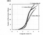
- FIG. 2 is a diagram showing an example of a fragmentation test result of a single fiber composite using the sizing agent-coated carbon fiber bundle according to the embodiment of the present invention.
- the sizing agent-coated carbon fiber bundle of the present invention is a sizing agent-coated carbon fiber bundle in which a sizing agent containing an aliphatic epoxy compound (C) and an aromatic epoxy compound (D) is applied to a carbon fiber bundle,
- the carbon fiber contained in the carbon fiber bundle has a fiber breakage number of 2.0 pieces / mm or more when the single fiber apparent stress is 15.3 GPa when measured using the fragmentation method of the single fiber composite, and A sizing agent-coated carbon fiber bundle having a fiber breakage number of 1.7 pieces / mm or less when the single fiber apparent stress is 12.2 GPa.
- the strand strength is predicted on the assumption that the load applied to the entire composite material is borne only by the carbon fiber. Since the strength of the carbon fiber per fiber cross-sectional area is 6 to 7 GPa or less, it has hitherto been discussed the relationship between the breaking probability of the carbon fiber monofilament and the strength of the carbon fiber reinforced composite material in the region above the strength. There was no. However, the inventors have found that when the OHT of the carbon fiber reinforced composite material is increased, the single fiber strength distribution in the high strength region strongly affects the OHT in combination with a specific matrix resin. .
- the single fiber strength test is a single fiber pull-out test from the adhesive, and in the single fiber strength test, stress is applied to several mm of fibers in the resin. I found out.
- the single fiber strength test even if the distance between the chucks is less than 5 mm, the substantial test length becomes longer. In particular, the shorter the chuck distance, the more the actual test length and the chuck distance are different. It was found that the single fiber strength distribution in the test length region could not be evaluated.
- the inventors have found a method for evaluating the single fiber strength distribution by a fragmentation test of a single fiber composite.
- the fragmentation test of the single fiber composite and the result of the single fiber strength distribution calculated from the single fiber strength test of the test length of 25 mm are in good agreement. It became clear that it was excellent as an evaluation method of single fiber strength distribution.
- the matrix resin used for the single fiber composite is appropriately selected and the adhesive strength at the single fiber-matrix resin interface is set to a certain level, the strength distribution can be evaluated with high accuracy up to a short test length of about 1 mm. Became clear.
- the fragmentation method of a single fiber composite is a method of counting the number of fiber breaks at each strain while giving the strain stepwise to a composite in which carbon fiber single fibers are embedded in a resin (single fiber composite). .
- the single fiber strength distribution of the carbon fiber can be examined. Details of the measurement using the fragmentation method will be described later.
- the difference between the single fiber composite strain and the fiber strain and the elastic modulus of the single fiber at each fiber strain are taken into account. There is a need.
- the elastic modulus of carbon fiber has nonlinearity of elastic modulus that increases as strain increases, and the exact fiber stress when the fiber breaks cannot be obtained by simple calculation.
- the single fiber apparent stress indicates a product of single fiber composite strain and single fiber elastic modulus of carbon fiber.
- the single fiber composite strain When fiber breakage occurs, there is a difference between the single fiber composite strain and the fiber strain because the fiber stress recovers as the distance from the fiber breakage portion increases. Therefore, even if the single fiber composite strain is increased, the maximum fiber stress may hardly increase. This creates a difference between single fiber composite strain and maximum fiber stress.
- the difference between the single fiber apparent stress and the maximum fiber stress is often very small up to 1.0 fiber breaks / mm. Although the difference increases as the number of fiber breaks further increases, there is a correlation between the apparent single fiber stress and the maximum fiber stress. Therefore, as a simple method, it is appropriate to use the single fiber apparent stress as an evaluation scale.
- the number of fiber breaks is 1.7 when the single fiber apparent stress is 12.2 GPa.
- Pieces / mm or less preferably 1.5 pieces / mm or less, more preferably 1.3 pieces / mm or less, and most preferably 1.0 pieces / mm or less.
- the single fiber strength of the carbon fiber is dominant as a factor of the breakage of the carbon fiber under this degree of stress.
- the inventors have found that in order to improve OHT, it is important that the single fiber strength of the carbon fiber, particularly the single fiber strength at a short fiber length, is high. That is, when the number of fiber breaks exceeds 1.7 pieces / mm, the OHT decreases due to the lack of single fiber strength of the carbon fiber. Therefore, the number of fiber breaks is set to 1.7 pieces / mm or less. good. Furthermore, it is more preferable that the number of fiber breaks is 1.3 pieces / mm or less because the single fiber strength of the carbon fiber is sufficiently high, and OHT is not limited to a specific resin.
- the sizing agent-coated carbon fiber bundle has a number of fiber breaks of 0.8 when the single fiber apparent stress is 10.0 GPa when the contained carbon fiber is measured using the fragmentation method of a single fiber composite. / Mm or less, more preferably 0.7 pieces / mm or less, still more preferably 0.5 pieces / mm or less.
- the number of fiber breaks exceeds 0.8 / mm, OHT is lowered due to insufficient single fiber strength of the carbon fiber.
- the number of fiber breaks is 0.8 pieces / mm or less, since the single fiber strength of the carbon fiber is high, fiber breakage can be suppressed in a wide range around the carbon fiber composite material circular hole at the time of the OHT test, OHT increases.
- the sizing agent-coated carbon fiber bundle has a number of fiber breaks of 0.3 when the single fiber apparent stress is 6.8 GPa when the contained carbon fiber is measured using the fragmentation method of a single fiber composite. / Mm or less, more preferably 0.2 pieces / mm or less, and still more preferably 0.1 pieces / mm or less. If the fiber stress at which the number of fiber breaks is around 0.3 / mm is too low, stress concentration on the adjacent fibers of the broken fiber in the carbon fiber reinforced composite material is likely to be induced. Therefore, a high OHT can be maintained by setting the number of fiber breaks to 0.3 pieces / mm or less.
- the number of fiber breaks was 1.7 pieces / piece when the single fiber composite strain was 3.6%. It is preferably mm or less, more preferably 1.5 pieces / mm or less, still more preferably 1.0 pieces / mm or less.
- OHT is decreased due to insufficient single fiber strength of the carbon fiber, and the smaller the number of fiber breaks, the higher the single fiber strength of the carbon fiber, which is preferable. .
- the number of fiber breaks is 0.1 when the single fiber composite strain is 2.0%.
- the number is preferably not more than pieces / mm, more preferably not more than 0.08 pieces / mm, and still more preferably not more than 0.06 pieces / mm. If the fiber stress at which the number of fiber breaks is near 0.1 pieces / mm is too low, stress concentration on the adjacent fibers of the broken fibers in the composite material is likely to be induced. By setting it as below, high OHT can be maintained.
- the sizing agent-coated carbon fiber bundle of the present invention has a fiber breakage number of 2 when the apparent single fiber stress is 15.3 GPa when the carbon fiber contained is measured using the fragmentation method of a single fiber composite. 0.0 piece / mm or more, preferably 2.5 piece / mm or more, more preferably 3.0 piece / mm or more. Unlike the case where the single fiber apparent stress is 12.2 GPa, the cause of the breakage of the carbon fiber under such a high stress is considered to be dominated by the interfacial shear strength at the fiber / resin interface. In the fragmentation method, the interfacial shear strength at the fiber / resin interface can be examined in addition to examining the single fiber strength of the carbon fiber.
- the single fiber composite When the single fiber elastic modulus of the carbon fiber is low, the single fiber composite may be broken before the single fiber apparent stress is loaded up to 15.3 GPa, but when the number of fiber breaks is saturated, Can be substituted.
- saturation means when the increase in the number of fiber breaks is 0.2 pieces / mm when the single fiber composite strain is increased by 1%.
- the sizing agent-coated carbon fiber bundle has a number of fiber breaks of 2.0 / cm2 when the single fiber composite strain is 4.5% when the contained carbon fiber is measured using the fragmentation method of a single fiber composite. It is preferable that it is mm or more, more preferably 3.0 pieces / mm or more. Even when the single fiber composite strain is 4.5%, the number of fiber breaks is often not saturated, but if the number of fiber breaks at that strain is substantially evaluated, it is sufficient to evaluate the height of interfacial adhesion. . When the number of fiber breaks is 2.0 pieces / mm or more, when the number of breaks increases due to a decrease in interfacial adhesion, the fibers in the vicinity of the breaks easily bear fiber stress, and a high OHT can be maintained.
- the inventors have clarified that both the single fiber strength distribution of carbon fibers and the interfacial shear strength at the fiber / resin interface can be examined by using the fragmentation method.
- a high OHT was obtained when a sizing agent-coated carbon fiber bundle having a small number of fractures under a low stress and a large number of fractures under a high stress was used. It has been found that a carbon fiber reinforced composite material can be obtained.
- One aspect of the present invention is a sizing agent-coated carbon fiber bundle in which a sizing agent is applied to a carbon fiber bundle, and the carbon fiber contained in the carbon fiber bundle is measured using a fragmentation method of a single fiber composite.
- the single fiber apparent stress is 15.3 GPa
- the number of fiber breaks is 2.0 pieces / mm or more
- the single fiber apparent stress is 12.2 GPa
- the number of fiber breaks is 1.3 pieces / mm.
- a sizing agent-coated carbon fiber bundle that is not more than mm.
- the strand strength of the sizing agent-coated carbon fiber bundle is preferably 5.9 GPa or more, more preferably 6.4 GPa or more, more preferably 6.8 GPa or more, and more preferably 7.0 GPa or more. Preferably it is 7.2 GPa or more, More preferably, it is 7.5 GPa or more. Moreover, it is preferable that the strand elastic modulus of carbon fiber is 320 GPa or more, More preferably, it is 340 GPa or more, More preferably, it is 350 GPa or more. When the carbon fiber strain in the fragmentation method is converted into fiber stress, the strand elastic modulus is necessary. Essentially, it is important that the fiber breakage is small even at high fiber stress.
- the strand elastic modulus when the strand elastic modulus is less than 320 GPa OHT may decrease.
- the single fiber elastic modulus of the carbon fibers contained in the sizing agent-coated carbon fiber bundle is preferably 320 GPa or more, more preferably 340 GPa or more, and further preferably 350 GPa or more.
- the fragmentation method in order to evaluate the single fiber strength, it is important that the fiber breakage is small even at a high fiber stress rather than a low fiber breakage at a high single fiber composite strain. Convert.
- the strand elastic modulus or single fiber elastic modulus of the carbon fiber is required, and here, the single fiber elastic modulus is used.
- the higher the single fiber elastic modulus the higher the fiber stress is applied even if the composite material single fiber composite strain is low.
- OHT may decrease when the single fiber elastic modulus is less than 320 GPa due to the relationship with the matrix resin characteristics.
- the single fiber elastic modulus of the carbon fiber can be determined based on JIS-R-7606 (2000). That is, in the single fiber tensile test, the slip occurs between the carbon fiber and the adhesive of the chuck part in the chuck, so it is not possible to accurately measure the single fiber elastic modulus. However, the longer the gauge length, the smaller the error. Therefore, the gauge length is 50 mm.
- the strain range when measuring the single fiber modulus is the entire range from 0% strain to breakage.
- the sizing agent-coated carbon fiber bundle of the present invention is obtained by applying a sizing agent containing at least an aliphatic epoxy compound (C) and an aromatic epoxy compound (D) to a carbon fiber bundle.
- Carbon fiber consisting of only aromatic epoxy compound (D) as epoxy compound and coated with sizing agent that does not contain aliphatic epoxy compound (C) has low reactivity between sizing agent and matrix resin, and preserves prepreg for a long time.
- the change in physical properties is small.
- a rigid interface layer can be formed.
- the aromatic epoxy compound (D) is slightly inferior in adhesion between the carbon fiber and the matrix resin compared to the aliphatic epoxy compound (C) due to the rigidity of the compound.
- the carbon fiber coated with a sizing agent composed only of the aliphatic epoxy compound (C) as the epoxy compound has high adhesiveness with the matrix resin.
- the aliphatic epoxy compound (C) is derived from a flexible skeleton and a structure having a high degree of freedom, and the functional group of the carboxyl group and hydroxyl group on the surface of the carbon fiber and the aliphatic epoxy compound are strongly interacting with each other. It is considered possible to form an action.
- the aliphatic epoxy compound (C) exhibits high adhesiveness due to the interaction with the carbon fiber surface, while having high reactivity with the compound having a functional group represented by the curing agent in the matrix resin, When stored for a long time in this state, there is a problem that the structure of the interface layer changes due to the interaction between the matrix resin and the sizing agent, and the physical properties of the carbon fiber reinforced composite material obtained from the prepreg deteriorate.
- the aliphatic epoxy compound (C) and the aromatic epoxy compound (D) are mixed, the more highly polar aliphatic epoxy compound (C) is unevenly distributed on the carbon fiber side, and the sizing layer on the side opposite to the carbon fiber is the most. There is a phenomenon that an aromatic epoxy compound (D) having a low polarity is likely to be unevenly distributed in the outer layer. As a result of the inclined structure of the sizing layer, the aliphatic epoxy compound (C) has a strong interaction with the carbon fiber in the vicinity of the carbon fiber, whereby the adhesion between the carbon fiber and the matrix resin can be enhanced.
- the aromatic epoxy compound (D) present in a large amount in the outer layer plays a role of blocking the aliphatic epoxy compound (C) from the matrix resin when a prepreg is produced using a sizing agent-coated carbon fiber bundle.
- the reaction between the aliphatic epoxy compound (C) and the highly reactive component in the matrix resin is suppressed, so that stability during long-term storage is exhibited.
- the sizing agent contains an aliphatic epoxy compound (C) and an aromatic epoxy compound (D).
- the aliphatic epoxy compound (C) is preferably contained in an amount of 35 to 65% by mass based on the total amount of the applied sizing agent. Adhesiveness improves by containing 35 mass% or more. Moreover, when the content is 65% by mass or less, the prepreg produced using the obtained sizing agent-coated fiber has good physical properties of the obtained carbon fiber reinforced composite material even when stored for a long time.
- the content of the aliphatic epoxy compound (C) is more preferably 38% by mass or more, and further preferably 40% by mass or more. Moreover, 60 mass% or less is more preferable, and 55 mass% or more is further more preferable.
- the aromatic epoxy compound (D) is preferably contained in an amount of 35 to 60% by mass with respect to the total amount of the sizing agent.
- the aromatic epoxy compound (D) By containing 35% by mass or more of the aromatic epoxy compound (D), the composition of the aromatic compound in the outer layer of the sizing agent can be maintained high, so that the aliphatic epoxy compound and the matrix are highly reactive during long-term storage of the prepreg. Reduction in physical properties due to reaction with the reactive compound in the resin is suppressed.
- the content is 60% by mass or less, the above-described inclined structure in the sizing agent can be expressed, and the adhesiveness can be maintained, which is preferable.
- content of an aromatic epoxy compound (D) 37 mass% or more is more preferable, and 39 mass% or more is further more preferable. Moreover, 55 mass% or less is more preferable, and 45 mass% or more is further more preferable.
- the mass ratio (C) / (D) of the aliphatic epoxy compound (C) and the aromatic epoxy compound (D) is preferably 52/48 to 80/20.
- (C) / (D) is 52/48 or more, the ratio of the aliphatic epoxy compound (C) present on the carbon fiber surface is increased, and the adhesion between the carbon fiber and the matrix resin is improved.
- the composite properties such as tensile strength of the obtained carbon fiber reinforced resin are preferably increased.
- 80/20 or less is preferable because the amount of the highly reactive aliphatic epoxy compound present on the surface of the carbon fiber is reduced and the reactivity with the matrix resin can be suppressed.
- the mass ratio of (C) / (D) is more preferably 55/45 or more, and further preferably 60/40 or more. Moreover, 75/35 or less is more preferable, and 73/37 or less is further more preferable.
- the ratio (a) / (b) between the height (cps) of the component of energy (284.6 eV) and the height (cps) of the component of binding energy (286.1 eV) attributed to CO (b) It is preferably 0.50 to 0.90.
- the ratio of (a) / (b) is more preferably 0.55 or more, and further preferably 0.57 or more.
- the ratio (a) / (b) is preferably 0.80 or less, and more preferably 0.74 or less.
- a large ratio of (a) / (b) indicates that there are many compounds derived from aromatics on the sizing agent surface and few compounds derived from aliphatic esters.
- the sizing agent-coated carbon fiber bundle in which the ratio of (a) / (b) falls within the above specific range is excellent in adhesion to the matrix resin, and the sizing agent-coated carbon fiber bundle is used for a prepreg. In addition, there is little decrease in physical properties when the prepreg is stored for a long time.
- X-ray photoelectron spectroscopy is an analysis technique in which a sample is irradiated with X-rays in an ultra-high vacuum and the kinetic energy of photoelectrons emitted from the surface of the sample is measured with an apparatus called an energy analyzer.
- an energy analyzer By examining the kinetic energy of the photoelectrons emitted from the surface of the sample, the binding energy converted from the energy value of the X-rays incident on the sample can be uniquely obtained. From the binding energy and photoelectron intensity, it is possible to analyze the type and concentration of the element present on the outermost surface ( ⁇ nm) of the sample and its chemical state.
- the peak ratio (a) / (b) on the sizing agent surface of the sizing agent-coated fiber is determined by X-ray photoelectron spectroscopy according to the following procedure.
- the sizing agent-coated carbon fiber bundle was cut to 20 mm, spread and arranged on a copper sample support, and AlK ⁇ 1 , 2 was used as an X-ray source, and the sample chamber was kept at 1 ⁇ 10 ⁇ 8 Torr for measurement. Done.
- the binding energy value of the main peak of C 1s is adjusted to 286.1 eV.
- the peak area of C 1s is obtained by drawing a straight baseline in the range of 282 to 296 eV.
- a linear base line of 282 to 296 eV obtained by calculating the area at the C 1s peak is defined as the origin (zero point) of photoelectron intensity, and (b) the peak of the binding energy 286.1 eV attributed to the CO component is obtained.
- Ratio (a ′) of the height (cps) of the component of the binding energy (284.6 eV) to be produced and (b ′) the height (cps) of the component of the binding energy (286.1 eV) attributed to C—O / (B ′) is preferably 0.45 to 1.0.
- the sizing-coated carbon fiber was ultrasonically washed with an acetone solvent for 1 to 10 minutes and then rinsed with distilled water, and the remaining sizing agent adhering to the carbon fiber was 0.10 ⁇ 0. After controlling to the range of 0.05 mass%, the measurement may be performed by the method described above.
- the adhesion amount of the sizing agent is preferably in the range of 0.1 to 3.0 parts by mass, more preferably in the range of 0.2 to 3.0 parts by mass with respect to 100 parts by mass of the carbon fiber. When the amount of the sizing agent is within such a range, high OHT can be expressed.
- the amount of sizing agent deposited was 2 ⁇ 0.5g of sizing coated carbon fiber, and the amount of mass change before and after the heat treatment when the heat treatment was performed at 450 ° C. in a nitrogen atmosphere for 15 minutes was sizing before the heat treatment. It can obtain
- the adhesion amount of the aliphatic epoxy compound (C) is preferably in the range of 0.05 to 2.0 parts by mass, more preferably 0.2 to 2.0 parts by mass with respect to 100 parts by mass of the carbon fiber. Range. More preferably, it is 0.3 to 1.0 part by mass.
- the adhesion amount of the aliphatic epoxy compound (C) is 0.05 parts by mass or more, the aliphatic epoxy compound (C) on the carbon fiber surface is preferable because the adhesion between the sizing agent-coated carbon fiber bundle and the matrix resin is improved. .
- the aliphatic epoxy compound (C) is an epoxy compound that does not contain an aromatic ring. Since it has a flexible skeleton with a high degree of freedom, it can have a strong interaction with carbon fibers.
- the aliphatic epoxy compound (C) is an epoxy compound having one or more epoxy groups in the molecule.
- the number of epoxy groups in the molecule is preferably 2 or more, and more preferably 3 or more.
- the aliphatic epoxy compound (C) is preferably an epoxy compound having a total of 3 or more of two or more functional groups, and more preferably an epoxy compound having a total of 4 or more of two or more functional groups.
- the functional group other than the epoxy group possessed by the epoxy compound is preferably one selected from a hydroxyl group, an amide group, an imide group, a urethane group, a urea group, a sulfonyl group, and a sulfo group.
- an epoxy compound having three or more epoxy groups or other functional groups in the molecule even if one epoxy group forms a covalent bond with an oxygen-containing functional group on the carbon fiber surface, the remaining two or more The epoxy group or other functional group can form a covalent bond or a hydrogen bond with the matrix resin, and the adhesion is further improved.
- the epoxy equivalent of the aliphatic epoxy compound (C) is preferably less than 360 g / mol, more preferably less than 270 g / mol, and even more preferably less than 180 g / mol.
- the epoxy equivalent is less than 360 g / mol, an interaction with the carbon fiber is formed at a high density, and the adhesion between the carbon fiber and the matrix resin is further improved.
- the aliphatic epoxy compound (C) include, for example, a glycidyl ether type epoxy compound derived from a polyol, a glycidyl amine type epoxy compound derived from an amine having a plurality of active hydrogens, and a glycidyl derived from a polycarboxylic acid.
- a glycidyl ether type epoxy compound derived from a polyol examples include an ester type epoxy compound and an epoxy compound obtained by oxidizing a compound having a plurality of double bonds in the molecule.
- Examples of the glycidyl ether type epoxy compound include a glycidyl ether type epoxy compound obtained by a reaction between epichlorohydrin and a polyol. Further, as glycidyl ether type epoxy compounds, ethylene glycol, diethylene glycol, triethylene glycol, tetraethylene glycol, polyethylene glycol, propylene glycol, dipropylene glycol, tripropylene glycol, tetrapropylene glycol, polypropylene glycol, trimethylene glycol, 1,2 -Butanediol, 1,3-butanediol, 1,4-butanediol, 2,3-butanediol, polybutylene glycol, 1,5-pentanediol, neopentyl glycol, 1,6-hexanediol, 1,4 -Cyclohexanedimethanol, hydrogenated bisphenol A, hydrogenated bisphenol F, glycerol, diglycerol
- Examples of the glycidylamine type epoxy compound include an epoxy compound obtained by reaction of 1,3-bis (aminomethyl) cyclohexane and epichlorohydrin.
- Examples of the glycidyl ester type epoxy compound include an epoxy compound obtained by reacting dimer acid with epichlorohydrin.
- Examples of the epoxy compound obtained by oxidizing a compound having a plurality of double bonds in the molecule include an epoxy compound having an epoxycyclohexane ring in the molecule. Furthermore, the epoxy compound includes epoxidized soybean oil.
- Examples of the aliphatic epoxy compound (C) include epoxy compounds such as triglycidyl isocyanurate in addition to these epoxy compounds.
- Examples of the compound having a hydroxyl group in addition to the epoxy group include sorbitol type polyglycidyl ether and glycerol type polyglycidyl ether.
- sorbitol type polyglycidyl ether examples include sorbitol type polyglycidyl ether and glycerol type polyglycidyl ether.
- “Denacol (registered trademark)” EX-611, EX-612, EX-614, EX-614B, EX-622, EX-512, EX-521, EX-421, EX-313, EX-314 And EX-321 manufactured by Nagase ChemteX Corporation.
- Examples of the compound having an amide group in addition to the epoxy group include an amide-modified epoxy compound.
- the amide-modified epoxy can be obtained by reacting an epoxy group of an epoxy compound having two or more epoxy groups with a carboxyl group of an aliphatic dicarboxylic acid amide.
- Examples of the compound having a urethane group in addition to the epoxy group include a urethane-modified epoxy compound.
- a urethane-modified epoxy compound Specifically, “Adeka Resin (registered trademark)” EPU-78-13S, EPU-6, EPU-11, EPU-15, EPU-16A, EPU-16N, EPU-17T-6, EPU-1348 and EPU-1395 (Made by ADEKA Corporation).
- a polyvalent isocyanate equivalent to the amount of the hydroxyl group by reacting the isocyanate residue of the obtained reaction product with the hydroxyl group in the polyvalent epoxy compound.
- examples of the polyvalent isocyanate used include hexamethylene diisocyanate, isophorone diisocyanate, and norbornane diisocyanate.
- Examples of the compound having a urea group in addition to the epoxy group include a urea-modified epoxy compound.
- a urea-modified epoxy can be obtained by reacting an epoxy group of an epoxy compound having two or more epoxy groups with a carboxyl group of an aliphatic dicarboxylic acid urea.
- aliphatic epoxy compound (C) ethylene glycol, diethylene glycol, triethylene glycol, tetraethylene glycol, polyethylene glycol, propylene glycol, dipropylene glycol, tripropylene glycol, tetrapropylene glycol, from the viewpoint of high adhesion among the above-mentioned Polypropylene glycol, trimethylene glycol, 1,2-butanediol, 1,3-butanediol, 1,4-butanediol, 2,3-butanediol, polybutylene glycol, 1,5-pentanediol, neopentyl glycol, 1,6-hexanediol, 1,4-cyclohexanedimethanol, glycerol, diglycerol, polyglycerol, trimethylolpropane, pentaerythritol, sodium Bitoru, and a polyol selected from arabitol, glycidyl ether type
- the aromatic epoxy compound (D) is an epoxy compound having one or more aromatic rings in the molecule.
- the aromatic ring may be an aromatic ring hydrocarbon consisting only of carbon, or a heteroaromatic ring such as furan, thiophene, pyrrole or imidazole containing a heteroatom such as nitrogen or oxygen.
- the aromatic ring may be a polycyclic aromatic ring such as naphthalene or anthracene.
- a so-called interface layer in the vicinity of the carbon fiber may be affected by the carbon fiber or the sizing agent and have different characteristics from the matrix resin.
- the epoxy compound has one or more aromatic rings
- a rigid interface layer is formed, the stress transmission ability between the carbon fiber and the matrix resin is improved, and the mechanical properties such as 0 ° tensile strength of the fiber reinforced composite material are improved. improves.
- the hydrophobicity is improved by the aromatic ring, so that the interaction with the carbon fiber is weaker than that of the aliphatic epoxy compound, and the aliphatic epoxy compound can be covered and exist in the outer layer of the sizing layer.
- a sizing agent-coated carbon fiber bundle is used for a prepreg, it is preferable because a change with time when stored for a long period of time can be suppressed. Having two or more aromatic rings is more preferable because long-term stability due to the aromatic rings is improved.
- the number of epoxy groups in the aromatic epoxy compound (D) is preferably 2 or more, more preferably 3 or more in the molecule. Moreover, it is preferable that it is 10 or less.
- the aromatic epoxy compound (D) is preferably an epoxy compound having a total of 3 or more of two or more functional groups in the molecule, and preferably an epoxy compound having a total of 4 or more of two or more functional groups. More preferred.
- the functional group other than the epoxy group possessed by the epoxy compound is preferably one selected from a hydroxyl group, an amide group, an imide group, a urethane group, a urea group, a sulfonyl group, and a sulfo group.
- an epoxy compound having three or more epoxy groups or other functional groups in the molecule even if one epoxy group forms a covalent bond with an oxygen-containing functional group on the carbon fiber surface, the remaining two or more The epoxy group or other functional group can form a covalent bond or a hydrogen bond with the matrix resin, and the adhesion is further improved.
- the epoxy equivalent of the aromatic epoxy compound (D) is preferably less than 360 g / mol, more preferably less than 270 g / mol, and even more preferably less than 180 g / mol.
- the epoxy equivalent is less than 360 g / mol, covalent bonds are formed at a high density, and the adhesion between the carbon fiber and the matrix resin is further improved.
- aromatic epoxy compound (D) examples include, for example, a glycidyl ether type epoxy compound derived from a polyol, a glycidyl amine type epoxy compound derived from an amine having a plurality of active hydrogens, and a glycidyl derived from a polycarboxylic acid.
- examples thereof include an ester type epoxy compound and an epoxy compound obtained by oxidizing a compound having a plurality of double bonds in the molecule.
- Examples of the glycidyl ether type epoxy compound include bisphenol A, bisphenol F, bisphenol AD, bisphenol S, tetrabromobisphenol A, phenol novolac, cresol novolac, hydroquinone, resorcinol, 4,4′-dihydroxy-3,3 ′, 5. , 5'-tetramethylbiphenyl, 1,6-dihydroxynaphthalene, 9,9-bis (4-hydroxyphenyl) fluorene, tris (p-hydroxyphenyl) methane, and tetrakis (p-hydroxyphenyl) ethane, and epichloro
- the epoxy compound obtained by reaction with hydrin is mentioned.
- an epoxy compound having a biphenylaralkyl skeleton is also exemplified as the glycidyl ether type epoxy.
- Examples of the glycidylamine type epoxy compound include N, N-diglycidylaniline and N, N-diglycidyl-o-toluidine.
- epoxy compounds obtained by the reaction of m-xylylenediamine, m-phenylenediamine, 4,4′-diaminodiphenylmethane and 9,9-bis (4-aminophenyl) fluorene with epichlorohydrin can be mentioned.
- epoxy compounds obtained by reacting both the hydroxyl group and amino group of aminophenols of m-aminophenol, p-aminophenol, and 4-amino-3-methylphenol with epichlorohydrin are mentioned. It is done.
- Examples of the glycidyl ester type epoxy compound include an epoxy compound obtained by reacting phthalic acid, terephthalic acid, or hexahydrophthalic acid with epichlorohydrin.
- epoxy compounds synthesized from the above-mentioned epoxy compounds for example, bisazol A diglycidyl ether and tolylene diisocyanate are synthesized by an oxazolidone ring formation reaction. And epoxy compounds.
- Examples of the compound having an amide group in addition to the epoxy group include glycidyl benzamide and an amide-modified epoxy compound.
- the amide-modified epoxy compound can be obtained by reacting an epoxy group of an epoxy compound having two or more epoxy groups with a carboxyl group of a dicarboxylic acid amide containing an aromatic ring.
- Examples of the compound having an imide group in addition to the epoxy group include glycidyl phthalimide. Specific examples include “Denacol (registered trademark)” EX-731 (manufactured by Nagase ChemteX Corporation).
- the terminal hydroxyl group of polyethylene oxide monoalkyl ether is reacted with a polyvalent isocyanate containing an aromatic ring having a reaction equivalent to the amount of the hydroxyl group, and then the reaction product obtained
- the epoxy compound obtained by making an isocyanate residue react with the hydroxyl group in a polyhydric epoxy compound is mentioned.
- examples of the polyvalent isocyanate used include 2,4-tolylene diisocyanate, metaphenylene diisocyanate, paraphenylene diisocyanate, diphenylmethane diisocyanate, triphenylmethane triisocyanate, and biphenyl-2,4,4′-triisocyanate. It is done.
- Examples of the compound having a urea group in addition to the epoxy group include a urea-modified epoxy compound.
- the urea-modified epoxy compound can be obtained by reacting the epoxy group of an epoxy compound containing an aromatic ring having two or more epoxy groups with the carboxyl group of the dicarboxylic acid urea.
- Examples of the compound having a sulfonyl group in addition to the epoxy group include bisphenol S-type epoxy.
- Examples of the compound having a sulfo group in addition to the epoxy group include glycidyl p-toluenesulfonate and glycidyl 3-nitrobenzenesulfonate.
- the aromatic epoxy compound (D) is a phenol novolac type epoxy compound, a cresol novolak type epoxy compound, tetraglycidyl diaminodiphenylmethane, a bisphenol A type epoxy compound or a bisphenol F type epoxy compound
- a bisphenol A type epoxy compound or a bisphenol F type epoxy compound is more preferable.
- the sizing agent may contain one or more components other than the aliphatic epoxy compound (C) and the aromatic epoxy compound (D).
- Accelerator that enhances adhesion between carbon fiber and sizing agent. Improves handling, scratch resistance, and fluff resistance by imparting convergence or flexibility to sizing agent-coated carbon fiber bundle, and impregnation of matrix resin. Can be improved.
- auxiliary components such as a dispersant and a surfactant may be added.
- the epoxy equivalent of the sizing agent applied to the carbon fiber is preferably 350 to 550 g / mol. It is preferable that the epoxy equivalent is 550 g / mol or less because the adhesion between the carbon fiber coated with the sizing agent and the matrix resin is improved. In addition, when the sizing agent-coated carbon fiber bundle is used for the prepreg, the epoxy equivalent of 350 g / mol or more can suppress the reaction between the resin component used in the prepreg and the sizing agent. Is preferable because the physical properties of the obtained carbon fiber reinforced composite material become good even when stored for a long time.
- the epoxy equivalent of the sizing agent applied to the carbon fiber is determined by immersing the sizing agent-coated fiber in a solvent typified by N, N-dimethylformamide and elution from the fiber by ultrasonic cleaning.
- the epoxy group can be opened and determined by acid-base titration.
- the epoxy equivalent is more preferably 360 g / mol or more, and still more preferably 380 g / mol or more.
- 530 g / mol or less is more preferable, and 500 g / mol or less is further more preferable.
- the epoxy equivalent of the sizing agent applied to the carbon fiber can be controlled by the epoxy equivalent of the sizing agent used for application and the heat history in drying after application.
- the aliphatic epoxy compound (C) eluted from the sizing agent-coated fibers is preferably 0.3 parts by mass or less with respect to 100 parts by mass of the sizing agent-coated carbon fiber bundle.
- the elution amount is more preferably 0.1 parts by mass or less, and further preferably 0.05 parts by mass or less.
- the elution amount of the aliphatic epoxy compound (C) eluted from the sizing agent-coated fiber is determined by the following procedure.
- a sizing agent-coated carbon fiber bundle (0.1 g) was immersed in 10 ml of a solution in which acetonitrile and chloroform were mixed at a volume ratio of 9 to 1, and the sizing agent was eluted from the fibers by ultrasonic cleaning for 20 minutes. Collect 5 ml, evaporate the solvent in nitrogen, add the above-mentioned mixed solution of acetonitrile and chloroform to a volume of 0.2 ml, and make a constant volume to make a 25-fold concentrated solution.
- the solution is separated from the other peaks of the aliphatic epoxy compound (C) by liquid chromatography using a mixture of water and acetonitrile as a mobile phase and detected by an evaporative light scattering detector (ELSD). . Then, by creating a calibration curve using the peak area of the solution of the aliphatic epoxy compound (C) whose concentration is known in advance, and quantifying the concentration of the aliphatic epoxy compound (C) based on the calibration curve, The elution amount of the aliphatic epoxy compound (C) with respect to 100 parts by mass of the sizing agent-coated carbon fiber bundle is determined.
- ELSD evaporative light scattering detector
- the carbon fiber has a surface oxygen concentration (O / C), which is the ratio of the number of oxygen (O) and carbon (C) atoms on the fiber surface measured by X-ray photoelectron spectroscopy, of 0.05 to 0.00. Those within the range of 50 are preferred, more preferably within the range of 0.06 to 0.30, and even more preferably within the range of 0.07 to 0.25.
- O / C surface oxygen concentration
- an oxygen-containing functional group on the surface of the carbon fiber can be secured and strong adhesion with the matrix resin can be obtained.
- the surface oxygen concentration (O / C) is 0.50 or less, the decrease in the single fiber strength of the carbon fiber itself due to oxidation is suppressed, that is, the single fiber apparent stress by the fragmentation method of the single fiber composite is reduced.
- the number of fiber breaks at 12.2 GPa can be controlled to 1.7 pieces / mm or less.
- the surface oxygen concentration of the carbon fiber can be adjusted by an oxidation treatment described later.
- the surface oxygen concentration of the carbon fiber is determined by X-ray photoelectron spectroscopy according to the following procedure. After carbon fibers from which dirt and the like adhering to the carbon fiber surface have been removed with a solvent are cut into 20 mm and spread on a copper sample support table, AlK ⁇ 1 and 2 are used as an X-ray source in the sample chamber. Was measured at 1 ⁇ 10 ⁇ 8 Torr. As a correction value for the peak accompanying charging during measurement, the binding energy value of the C 1s main peak (peak top) is adjusted to 284.6 eV.
- the C 1s peak area is obtained by drawing a straight base line in the range of 282 to 296 eV
- the O 1s peak area is obtained by drawing a straight base line in the range of 528 to 540 eV.
- the surface oxygen concentration O / C is represented by an atomic ratio calculated by dividing the ratio of the O 1s peak area by the sensitivity correction value unique to the apparatus.
- the sensitivity correction value unique to the apparatus is 2.33.
- a carbon fiber bundle is a fiber bundle formed by bundling single carbon fibers.
- the number of single fibers is preferably 3000 to 48000, more preferably 10,000 to 20000.
- the total fineness of the sizing agent-coated carbon fiber bundle is preferably 400 to 3000 tex.
- the number of carbon fiber filaments is preferably 10,000 to 30,000.
- the single fiber diameter of the carbon fiber contained in the sizing agent-coated carbon fiber bundle is preferably 4.5 ⁇ m or less, more preferably 3.0 ⁇ m or less.
- the single fiber diameter is 4.5 ⁇ m or less, the probability of existence of surface defects can be reduced, so that the single fiber strength is increased, and the adhesion with the matrix resin is improved by increasing the surface area ratio of the carbon fibers, The stress transmission in the carbon fiber reinforced composite material is also uniform, resulting in a higher OHT.
- the larger the single fiber diameter of the carbon fiber the more easily the matrix resin is impregnated between the single fibers, and as a result, the OHT can be increased. Therefore, the single fiber diameter is preferably 2.0 ⁇ m or more.
- any method can be adopted as long as the numerical range described above can be achieved, but it can be controlled by adjusting the fineness of the polyacrylonitrile precursor fiber described later. .
- the sizing agent-coated carbon fiber bundle preferably has an average tearable distance of 300 to 710 mm.
- the average tearable distance is an index indicating the degree of entanglement of carbon fibers in the carbon fiber bundle.
- Fig. 1 shows how to measure the tearable distance.
- the fiber bundle 1 is cut to a length of 1160 mm, and one end 2 thereof is fixed on a horizontal base so as not to move with an adhesive tape (this point is referred to as a fixing point A).
- One end 3 of the fiber bundle that is not fixed is divided into two with a finger, and one of the ends is tensioned and fixed on the table so as not to move with an adhesive tape (this point is referred to as a fixing point B).
- the other end of the fiber bundle divided into two is moved along the table so that no slack occurs with the fixed point A as a fulcrum, and is stopped at position 4 where the linear distance from the fixed point B is 500 mm. (This point is called a fixed point C).
- the entanglement point 5 farthest from the fixed point A is found, and the distance projected on the straight line connecting the fixed point A and the fixed point B is the lowest scale.
- the entanglement point farthest from the fixed point A is the point where the linear distance from the fixed point A is the longest and three or more single fibers having no slack are entangled.
- the OHT can be increased by increasing the strength of the long-length carbon fiber bundle in the order of several meters. Therefore, a smaller average tearable distance is preferable.
- the average tearable distance of the sizing agent-coated carbon fiber bundle is 710 mm or less, when the prepreg is processed into a carbon fiber reinforced composite material, high tension can be applied to enhance the fiber alignment.
- the stress transmission in the carbon fiber reinforced composite material becomes more uniform, so that the OHT can be increased.
- the average tearable distance of the sizing agent-coated carbon fiber bundle is less than 300 mm, the fiber alignment is disturbed, and the fibers laminated in the 0 ° direction are less likely to concentrate stress, which may reduce OHT.
- the average tearable distance is more preferably 300 to 600 mm.
- the average tearable distance of the sizing agent-coated carbon fiber bundle can be controlled by controlling the average tearable distance at the time of the preliminary carbonized fiber bundle as described later.
- Bundle strength of carbon fiber bundles coated with a sizing agent can be generally calculated from a single fiber average strength and a Weibull shape factor indicating the strength distribution.
- the Weibull shape factor of carbon fiber is about 3 to 8.
- the bundle strength can be greatly increased even if the single fiber strength distribution of the carbon fibers is the same.
- the average tearable distance is in the above-described range, and the ratio of the tearable distance of 800 mm or more is preferably 15% or less.
- the effect described above can be further expanded by reducing the ratio.
- the ratio of the distance of 800 mm or more is the ratio of the number of times that the tearable distance was 800 mm or more out of 30 measurements when the tearable distance was measured 30 times as described above. That is.
- Ratio (%) of tearable distance of 800 mm or more number of times of tearable distance of 800 mm or more / 30 ⁇ 100.
- the ratio of the distance of 800 mm or more of the distance is 15% or more, the entangled state of the carbon fiber bundle is not controlled, and a portion having a low stress transmission ability between the single fibers is present in the carbon fiber bundle, When a high stretching tension is applied in the carbonization process, the quality may be lowered.
- the sizing agent-coated carbon fiber bundle preferably has a bundle strength of 1.9 to 4.0 GPa, more preferably 2.2 to 4.0 GPa, and even more preferably 2.10 GPa. 6 to 4.0 GPa.
- the bundle strength of a carbon fiber bundle having a test length of 10 m is 1.9 GPa or more, it is possible to enhance fiber alignment by applying high tension when processing into a carbon fiber reinforced composite material, and excellent in stress transmission between single fibers. As a result, OHT can be increased.
- 4.0 GPa is an industrial upper limit for the bundle strength of a carbon fiber bundle having a test length of 10 m. The greater the control length dependence coefficient of the carbon fiber bundle, the higher the bundle strength of the carbon fiber bundle.
- One aspect of the present invention is a sizing agent-coated carbon fiber bundle in which a sizing agent is applied to a carbon fiber bundle, the average tearable distance is 300 to 710 mm, the strand strength is 5900 MPa or more, and the strand elastic modulus is 320 GPa.
- the carbon fiber bundle is a sizing agent-coated carbon fiber bundle having a single fiber breaking number of 0.5 to 3 pieces / m and substantially no twist.
- substantially untwisted means that it is 1 turn or less per 1 m of fiber bundle even if twist is present.
- the number of single fiber breaks is the number of single fiber breaks per 1 m of carbon fiber bundle (pieces / m).
- a method for producing a carbon fiber bundle will be described.
- a precursor fiber made of a polyacrylonitrile polymer is prepared, and a carbon fiber bundle is obtained by subjecting the precursor fiber to a flame resistance process, a preliminary carbonization process, and a carbonization process.
- the polyacrylonitrile polymer suitably used for the precursor fiber for producing the sizing agent-coated carbon fiber of the present invention preferably has a weight average molecular weight of 500,000 to 1.110,000, and preferably 700,000 to 900,000. More preferred.
- a polyacrylonitrile polymer having a weight average molecular weight in a general range for carbon fibers, such as a weight average molecular weight of less than 500,000 is used, the molecular chain ends decrease because the connection between molecules in the fiber axis direction decreases. Due to the influence of the above, in the obtained carbon fiber, the single fiber strength is easily lowered in the high strength region.
- the polyacrylonitrile polymer preferably has a higher weight average molecular weight.
- a polyacrylonitrile polymer having a high molecular weight exceeding 1.110,000 needs to have a low polymer concentration when spinning as a polymer solution.
- voids are formed in the obtained carbon fiber, and the single fiber strength of the carbon fiber is likely to be lowered in a high strength region.
- the weight average molecular weight of the polyacrylonitrile polymer can be controlled by changing the amounts of monomers, initiators, chain transfer agents and the like during polymerization. Specifically, the weight average molecular weight can be increased by increasing the monomer concentration at the start of polymerization, decreasing the initiator concentration, and decreasing the chain transfer agent concentration.
- the weight average molecular weight and the intrinsic viscosity of the polyacrylonitrile polymer have a one-to-one relationship, and the intrinsic viscosity 4.0 can be converted to 1.11 million in terms of the weight average molecular weight.
- the polyacrylonitrile polymer means a polymer in which at least an acrylonitrile unit is a main constituent unit of a polymer skeleton.
- the main structural unit means that the unit occupies 90 to 100 mol% of the polymer skeleton.
- a preferred polyacrylonitrile polymer has a polydispersity Mz / Mw of 1.4 to 2.4.
- the larger Mz / Mw means that the higher molecular weight side contains components having different molecular weights. Even if Mz / Mw is less than 1.4 or Mz / Mw exceeds 2.4, the single fiber strength of the carbon fiber tends to decrease in the high strength region.
- the polyacrylonitrile polymer preferably contains a copolymer component from the viewpoint of improving the yarn-making property and efficiently performing the flameproofing treatment.
- a copolymer component from the viewpoint of improving the yarn-making property and efficiently performing the flameproofing treatment.
- the flameproofing reaction may be non-uniform.
- the copolymer component itself may be thermally decomposed and recognized as a carbon fiber defect.
- a preferable amount of the copolymerization component is 0.1 to 0.8% by mass.
- Preferred examples of the copolymer component include those having one or more carboxyl groups or amide groups from the above viewpoint.
- a small amount of a monomer having a high flame resistance promoting effect it is preferable to use a copolymer component having a carboxyl group rather than an amide group.
- the number of amide groups and carboxyl groups contained is more preferably two or more than one. From that viewpoint, acrylic acid, methacrylic acid, itaconic acid, crotonic acid, citraconic acid, ethacrylic acid, maleic acid and mesaconic acid are preferred, itaconic acid, maleic acid and mesaconic acid are more preferred, and itaconic acid is most preferred.
- polymerization method for producing the polyacrylonitrile polymer a known polymerization method can be selected.
- the method for producing the polyacrylonitrile precursor fiber includes a spinning process in which a spinning solution is discharged from a spinneret to a coagulation bath by a dry and wet spinning method, a water washing process in which the fiber obtained in the spinning process is washed in a water bath, and the water washing. It consists of a water bath stretching step for stretching the fiber obtained in the step in a water bath, and a drying heat treatment step for subjecting the fiber obtained in the water bath stretching step to a dry heat treatment. If necessary, it may further include a steam stretching step of steam stretching the fiber obtained in the drying heat treatment step.
- the spinning solution is obtained by dissolving the polyacrylonitrile polymer in a solvent in which polyacrylonitrile polymers such as dimethyl sulfoxide, dimethylformamide, and dimethylacetamide are soluble.
- a spinning solution having a polyacrylonitrile polymer concentration of 10 to 18% by mass is preferred.
- concentration of the spinning solution is less than 10% by mass, voids are formed in the carbon fiber, and the single fiber strength of the carbon fiber is likely to be lowered in the high strength region.
- the concentration of the spinning solution exceeds 18% by mass, it may be necessary to lower the weight average molecular weight of the polymer for spinnability.
- the coagulation bath preferably contains a solvent such as dimethyl sulfoxide, dimethylformamide and dimethylacetamide used as a solvent for the spinning solution and a so-called coagulation promoting component.
- a solvent such as dimethyl sulfoxide, dimethylformamide and dimethylacetamide used as a solvent for the spinning solution
- a so-called coagulation promoting component a component that does not dissolve the polyacrylonitrile polymer and is compatible with the solvent used in the spinning solution can be used.
- water it is preferable to use water as a coagulation promoting component.
- the water washing step it is preferable to perform water washing using a water washing bath having a plurality of stages at a temperature of 20 to 90 ° C. Further, the draw ratio in the water bath drawing step is preferably 1.3 to 5 times, more preferably 2 to 4 times.
- an oil agent made of silicone or the like it is preferable to apply an oil agent made of silicone or the like to the yarn for the purpose of preventing adhesion between single fibers.
- a silicone oil agent it is preferable to use a modified silicone, and it is preferable to use one containing an amino-modified silicone having high heat resistance.
- the steam stretching step it is preferable to stretch at least 3 times, more preferably 4 times or more, and even more preferably 5 times or more in pressurized steam.
- the polyacrylonitrile precursor fiber is preferably adjusted to have a fineness of 0.60 dtex or less, more preferably 0.41 dex or less, and further preferably 0.26 dtex or less. Such fineness can be controlled by adjusting the discharge amount of the spinning solution and the spinning speed.
- the polyacrylonitrile precursor fiber thus obtained is subjected to a flameproofing step to obtain a flameproofed fiber.
- the flameproofing step is preferably performed at as high a temperature as possible without causing a runaway reaction. Specifically, it is preferably performed in air at 200 to 300 ° C.
- the treatment time of the flameproofing step can be suitably selected within a range of preferably 10 to 100 minutes. The treatment time is preferably set so that the specific gravity of the obtained flame-resistant fiber is in the range of 1.3 to 1.4 for the purpose of improving the mechanical properties of the obtained carbon fiber.
- the flame resistant fiber obtained by the flame resistance process is subjected to a preliminary carbonization process to obtain a preliminary carbonized fiber.
- a preliminary carbonization process it is preferable to heat-treat the flame-resistant fiber in an inert atmosphere at a maximum temperature of 500 to 1200 ° C. until the specific gravity becomes 1.5 to 1.8.
- the pre-carbonized fiber obtained by the pre-carbonization step is subjected to a carbonization step to obtain carbon fiber.
- the preliminary carbonized fiber is heated to 1200 to 2000 ° C. in an inert atmosphere.
- the temperature of the carbonization step is preferably higher from the viewpoint of increasing the strand elastic modulus of the carbon fiber to be obtained, but if it is too high, the strength of the high strength region may decrease, and it is set in consideration of both. Is good.
- a more preferable temperature range is 1200 to 1800 ° C., and a further preferable temperature range is 1200 to 1600 ° C.
- the tension of the carbonization step is 4.9 ⁇ carbonization tension (mN / dtex) ⁇ ⁇ 0.0225 ⁇ (average tearing of the pre-carbonized fiber bundle is possible. Distance (mm)) + 23.5 (1)
- the carbonization process is performed within a range satisfying the above, and the pre-carbonized fiber bundle is substantially untwisted, and the carbon fiber bundle having an average tearable distance of 150 to 620 mm is prepared. Is the method.
- substantially untwisted means that it is 1 turn or less per 1 m of fiber bundle even if twist is present.
- the tension of the carbonization step is 9.8 ⁇ the tension of the carbonization step (mN / dtex) ⁇ ⁇ 0.0225 ⁇ (average tearable distance of pre-carbonized fiber bundle (mm) +23.5 (2) It is preferable that the carbonization step is performed within a range satisfying the above condition, the pre-carbonized fiber bundle is substantially untwisted, and the average tearable distance of the pre-carbonized fiber bundle is 150 to 620 mm.
- the strand elastic modulus of the carbon fiber bundle can be increased by increasing the crystallite size inside the carbon fiber as the maximum temperature in the carbonization process is increased.
- the tensile strength and adhesive strength of the obtained carbon fiber bundle are lowered by raising the maximum temperature of the carbonization step.
- the strand elastic modulus of the obtained carbon fiber bundle can be increased by increasing the tension of the carbonization process without increasing the maximum temperature of the carbonization process.
- the crystallite size inside the carbon fiber is preferably 1.2 nm or more and 2.5 nm or less, and more preferably 1.2 nm or more and 2.5 nm or less.
- the crystallite size is preferably controlled within the above range.
- the crystallite size can be controlled mainly by the carbonization temperature.
- the relationship between the crystallite size and the strand elastic modulus preferably satisfies the following formula. 50 ⁇ crystallite size (nm) + 200 ⁇ strand modulus ⁇ 50 ⁇ crystallite size (nm) +300
- the carbon fiber bundle can have excellent strand elastic modulus and single fiber strength balance. Satisfying the relational expression can be achieved by controlling the carbonization tension by controlling the tearable distance of the pre-carbonized fiber bundle within the range of the present invention.
- the tension (carbonization tension) in the carbonization step is represented by a value obtained by dividing the tension (mN) measured on the outlet side of the carbonization furnace by the fineness (dtex) of the polyacrylonitrile precursor fiber when it is completely dried. If the tension is lower than 4.9 mN / dtex, the crystallite orientation of the carbon fibers cannot be increased, and a high strand elastic modulus is not exhibited, so that OHT may be lowered. When the tension is set higher than 9.8 mN / dtex, the fiber alignment is improved and a state of excellent stress transmission between single fibers is formed. Since OHT can be improved, it is preferable.
- the tension is preferably higher from the viewpoint of increasing the strand elastic modulus of the carbon fiber to be obtained, but if it is too high, the process passability and the quality may be deteriorated, and therefore the range satisfying the formula (2). It is preferable to set by.
- the meaning of the first-order coefficient ⁇ 0.0225 on the right side of Equation (2) is the gradient of the tension that can be set as the average tearable distance increases, and the constant term 23.5 represents the average tearable distance to the limit. This tension can be set when the length is shortened.
- the tearable distance of the pre-carbonized fiber bundle in the carbonization process is an index representing the entangled state of the fiber bundle.
- the tearable distance of the preliminary carbonized fiber bundle is obtained in the same manner as the tearable distance of the carbonized fiber bundle described above.
- the hook drop method has been generally used as a method for evaluating the confounding state.
- the degree of entanglement (CF value) of the fiber bundle by the hook drop method is fixed to the upper part of the drooping device, and the weight is suspended at the lower end of the fiber bundle, as defined in JIS L1013 (2010).
- the average tearable distance is used instead of the degree of entanglement (CF value) obtained by the conventional hook drop method, and the distance is set to a specific range, whereby high strength of carbon fiber is obtained. It was found that a high stretching tension in the carbonization process can be expressed while avoiding a decrease in the strength of the region. In order to apply a high drawing tension in the carbonization process, it is necessary to create a fiber bundle state in which the stress transmission ability between single fibers is high. For that purpose, it is important to form a fine entanglement network between single fibers.
- the conventional hook drop method is an evaluation at a “point” using a hook, whereas the tearable distance is an evaluation at a “surface” that looks at the entire bundle. Due to this difference, in the carbonization process, It is considered that a state for expressing a high stretching tension can be appropriately defined.
- the tearable distance of the pre-carbonized fiber bundle is more preferably 150 to 500 mm.
- the variation in tear distance is small.
- the ratio of the distance of 800 mm or more is preferably 15% or less, and more preferably the ratio is 10% or less.
- the ratio of 800 mm or more of the distance is the ratio of the number of times that the tearable distance was 800 mm or more among the 30 measurements when the tearable distance was measured 30 times.
- the ratio of the distance of 800 mm or more is 15% or more, the entangled state is not controlled, and a portion having a low stress transmission ability between single fibers is present in the bundle. May cause degradation in quality and induce structural variations between single fibers and accompanying strength variations, making it impossible to control the single fiber strength distribution in the short length region of carbon fibers, resulting in OHT. Decreases.
- the ratio of 800 mm or more of the distance is calculated 30 times based on the above-described measurement of the tearable distance and calculated from the following formula.
- Ratio (%) of tearable distance of 800 mm or more frequency of tearable distance of 800 mm or more / 30 ⁇ 100.
- any method can be adopted as long as the above-described numerical range can be achieved, but confounding treatment with a fluid to the fiber bundle is preferably used. .
- the dynamic friction coefficient can be measured by a method described later, and can be controlled by the surface form, cross-sectional shape, and kind of oil applied to the fiber bundle forming the fiber bundle.
- the process of performing the fluid entanglement process may be any process of the polyacrylonitrile precursor fiber bundle manufacturing process, the flame resistance process, and the preliminary carbonization process.
- the polyacrylonitrile precursor fiber bundle is preferably produced in a process of producing a high degree of elongation of the polyacrylonitrile precursor fiber bundle, more preferably before the process oil is applied to the polyacrylonitrile precursor fiber bundle.
- the average tearable distance of the polyacrylonitrile precursor fiber bundle after the fluid entanglement treatment is preferably 100 to 500 mm, more preferably 100 mm.
- It is ⁇ 400 mm, more preferably 100 to 300 mm.
- the distance is less than 100 mm, the density of single fibers in the bundle increases, and in the flameproofing process, the inside of the bundle is not flameproofed, resulting in burn unevenness, thereby inducing structural variations and strength variations between the single fibers. As a result, the perforated plate tensile strength may decrease.
- the distance exceeds 500 mm, there is a possibility that the quality deteriorates or the yarn breaks when a high stretching tension is applied in the carbonization process.
- the fluid used for the fluid entanglement treatment either gas or liquid can be used, but air or nitrogen is preferable because it is inexpensive.
- the fluid is preferably sprayed onto the fiber bundle using a nozzle, and the shape of the nozzle that sprays the fluid is not particularly limited, but it is preferable to use one having 2 to 8 ejection holes.
- the arrangement of the ejection ports is not particularly limited, but an even number of ejection holes are arranged so as to surround the fiber bundle so that the angle formed by the fiber bundle longitudinal direction and the fluid blowing direction is in the range of 88 ° to 90 °. It is preferable to arrange the jet holes at positions facing each other so as to form a pair of two holes. Other conditions such as fiber bundle tension and fluid discharge pressure during the fluid entanglement process may be adjusted as appropriate so that the tearable distance is appropriate.
- the tension In the fluid entanglement treatment, it is preferable to set the tension to 2 to 5 mN / dtex-fiber bundle and set the fluid discharge pressure to 0.2 to 0.4 MPa-G. More preferably, the tension is 2 to 3 mN / dtex-fiber bundle, and the discharge pressure is 0.25 to 0.35 MPa-G. Moreover, it is preferable that the fiber bundle at the time of the fluid entanglement process is substantially untwisted. Here, “substantially untwisted” means that it is 1 turn or less per 1 m of fiber bundle even if twist is present.
- the swirl movement of the single fiber may be suppressed, and the formation of entanglement may also be suppressed.
- the tension at the time of fluid entanglement treatment is lowered below 2 mN / dtex-fiber bundle, the swirl movement of the single fibers constituting the fiber bundle is promoted and entanglement is likely to be formed, but the fiber bundle comes into contact with the nozzle. Yarn pain and scratches may occur, which may cause deterioration in quality and decrease in strand strength.
- the formation of the entanglement in the longitudinal direction of the fiber bundle becomes non-uniform, and a portion having a low degree of entanglement may occur.
- the pressure during the fluid entanglement process is higher than 0.4 MPa-G, the fluid may cause thread pain and scratches, which may cause deterioration in quality and decrease in strand strength.
- the pressure during the fluid entanglement process is lower than 0.2 MPa-G, the swirl movement of the single fibers may be suppressed, and the formation of entanglement may be suppressed.
- the number of single fibers constituting the fiber bundle during the fluid entanglement treatment is preferably 12,000 or less, more preferably 6000 or less. As the number of single fibers constituting the fiber bundle increases, the entanglement of the single fibers becomes easier to form, but a portion where no entanglement is imparted is also formed in the fiber bundle, and the entanglement formation may become uneven.
- the fluid entanglement treatment is performed on the polyacrylonitrile precursor fiber bundle, after the fluid entanglement treatment, two or more polyacrylonitrile precursor fiber bundles are combined and adjusted to the number of filaments necessary as a final product.
- the obtained carbon fiber bundle is preferably subjected to an oxidation treatment to introduce an oxygen-containing functional group in order to improve adhesion with the matrix resin.
- an oxidation treatment method gas phase oxidation, liquid phase oxidation and liquid phase electrolytic oxidation are used. From the viewpoint of high productivity and uniform processing, liquid phase electrolytic oxidation is preferably used.
- Examples of the electrolytic solution used in the liquid phase electrolytic oxidation include an acidic electrolytic solution and an alkaline electrolytic solution. From the viewpoint of adhesiveness, it is more preferable to apply a sizing agent after liquid-phase electrolytic oxidation of a carbon fiber bundle in an alkaline electrolyte.
- Examples of the acidic electrolyte include inorganic acids such as sulfuric acid, nitric acid, hydrochloric acid, phosphoric acid, boric acid, and carbonic acid, organic acids such as acetic acid, butyric acid, oxalic acid, acrylic acid, and maleic acid, or ammonium sulfate and ammonium hydrogen sulfate. And the like. Of these, sulfuric acid and nitric acid exhibiting strong acidity are preferably used.
- alkaline electrolyte examples include aqueous solutions of hydroxides such as sodium hydroxide, potassium hydroxide, magnesium hydroxide, calcium hydroxide and barium hydroxide, sodium carbonate, potassium carbonate, magnesium carbonate, calcium carbonate, Aqueous solutions of carbonates such as barium carbonate and ammonium carbonate, aqueous solutions of bicarbonates such as sodium bicarbonate, potassium bicarbonate, magnesium bicarbonate, calcium bicarbonate, barium bicarbonate and ammonium bicarbonate, ammonia, tetraalkylammonium hydroxide And an aqueous solution of hydrazine.
- hydroxides such as sodium hydroxide, potassium hydroxide, magnesium hydroxide, calcium hydroxide and barium hydroxide
- Aqueous solutions of carbonates such as barium carbonate and ammonium carbonate
- bicarbonates such as sodium bicarbonate, potassium bicarbonate, magnesium bicarbonate, calcium bicarbonate, bar
- an aqueous solution of ammonium carbonate and ammonium hydrogen carbonate or an aqueous solution of tetraalkylammonium hydroxide exhibiting strong alkalinity is preferably used.
- the concentration of the electrolytic solution is preferably in the range of 0.01 to 5 mol / liter, more preferably in the range of 0.1 to 1 mol / liter.
- concentration of the electrolytic solution is 0.01 mol / liter or more, the electrolytic treatment voltage is lowered, which is advantageous for the operating cost.
- concentration of the electrolytic solution is 5 mol / liter or less, it is advantageous from the viewpoint of safety.
- the temperature of the electrolytic solution is preferably in the range of 10 to 100 ° C., more preferably in the range of 10 to 40 ° C.
- the temperature of the electrolytic solution is 10 ° C. or higher, the efficiency of the electrolytic treatment is improved, which is advantageous for the operating cost.
- the temperature of the electrolytic solution is 100 ° C. or lower, it is advantageous from the viewpoint of safety.
- the amount of electricity in the liquid phase electrolytic oxidation is preferably optimized in accordance with the carbonization degree of the carbon fiber, and a larger amount of electricity is required when processing high-modulus carbon fiber.
- the current density in the liquid phase electrolytic oxidation is preferably in the range of 1.5 to 1000 amperes / m 2 per 1 m 2 of the surface area of the carbon fiber in the electrolytic treatment solution, more preferably 3 to 500 amperes / m 2 . Within range. When the current density is 1.5 amperes / m 2 or more, the efficiency of the electrolytic treatment is improved, which is advantageous for the operating cost. On the other hand, when the current density is 1000 amperes / m 2 or less, it is advantageous from the viewpoint of safety.
- the total amount of electrolytic electricity employed in the electrolytic treatment is preferably 3 to 300 coulomb / g per gram of carbon fiber. If the total amount of electrolytic electricity is less than 3 coulombs / g, functional groups may not be sufficiently imparted to the carbon fiber surface, and the number of fiber breaks when the single fiber apparent stress by the fragmentation method of the single fiber composite is 15.3 GPa. May be less than 2.0 pieces / mm. On the other hand, when the total amount of electrolytic electricity exceeds 300 coulombs / g, defects on the surface of the carbon fiber single fiber are enlarged, and the number of fiber breaks when the single fiber apparent stress is 12.2 GPa by the fragmentation method of the single fiber composite is 1. May exceed 7 / mm.
- the carbon fiber is preferably washed and dried.
- a cleaning method for example, a dip method and a spray method can be used.
- a dip method from a viewpoint that washing
- a dip method vibrating a carbon fiber with an ultrasonic wave.
- the drying temperature is preferably 250 ° C. or lower, more preferably 210 ° C. or lower.
- the prepreg of the present invention is a prepreg containing the sizing agent-coated carbon fiber bundle of the present invention and a thermosetting resin.
- the thermosetting resin contains an epoxy compound (A) and an aromatic amine curing agent (B).
- the sizing agent-coated carbon fiber bundle of the present invention exhibits high OHT in combination with a thermosetting resin containing an epoxy compound (A) and an aromatic amine curing agent (B).
- the epoxy compound (A) used for the epoxy resin is not particularly limited, and is a bisphenol type epoxy compound, an amine type epoxy compound, a phenol novolak type epoxy compound, a cresol novolak type epoxy compound, a resorcinol type epoxy compound, a glycidyl aniline type.
- epoxy compounds phenol aralkyl type epoxy compounds, naphthol aralkyl type epoxy compounds, dicyclopentadiene type epoxy compounds, epoxy compounds having a biphenyl skeleton, isocyanate-modified epoxy compounds, tetraphenylethane type epoxy compounds, triphenylmethane type epoxy compounds, etc.
- One or more types can be selected and used.
- the bisphenol type epoxy compound is obtained by glycidylation of two phenolic hydroxyl groups of a bisphenol compound.
- not only a monomer but the high molecular weight body which has several repeating units can also be used conveniently.
- bisphenol A type epoxy compounds include “jER (registered trademark)” 825, 828, 834, 1001, 1002, 1003, 1003F, 1004, 1004AF, 1005F, 1006FS, 1007, 1009, 1010 (and above, Mitsubishi Chemical) Etc.).
- brominated bisphenol A type epoxy compound examples include “jER (registered trademark)” 505, 5050, 5051, 5054, 5057 (manufactured by Mitsubishi Chemical Corporation).
- Examples of commercially available hydrogenated bisphenol A type epoxy compounds include ST5080, ST4000D, ST4100D, and ST5100 (manufactured by Nippon Steel Chemical Co., Ltd.).
- bisphenol F type epoxy compounds include “jER (registered trademark)” 806, 807, 4002P, 4004P, 4007P, 4009P, 4010P (above, manufactured by Mitsubishi Chemical Corporation), “Epiclon (registered trademark)” 830. 835 (above, manufactured by DIC Corporation), “Epototo (registered trademark)” YDF2001, YDF2004 (above, manufactured by Nippon Steel Chemical Co., Ltd.), and the like.
- Examples of the tetramethylbisphenol F type epoxy compound include YSLV-80XY (manufactured by Nippon Steel Chemical Co., Ltd.).
- Examples of the bisphenol S type epoxy compound include “Epiclon (registered trademark)” EXA-154 (manufactured by DIC Corporation).
- amine-type epoxy compound examples include tetraglycidyldiaminodiphenylmethane, triglycidylaminophenol, triglycidylaminocresol, tetraglycidylxylylenediamine, halogens thereof, alkynol-substituted products, hydrogenated products, and the like.
- tetraglycidyldiaminodiphenylmethane Commercially available products of tetraglycidyldiaminodiphenylmethane include “Sumiepoxy (registered trademark)” ELM434 (manufactured by Sumitomo Chemical Co., Ltd.), YH434L (manufactured by Nippon Steel Chemical Co., Ltd.), and “jER (registered trademark)” 604 (Mitsubishi Chemical). (Manufactured by Co., Ltd.), “Araldide (registered trademark)” MY720, MY721, MY725 (manufactured by Huntsman Advanced Materials Co., Ltd.).
- triglycidylaminophenol or triglycidylaminocresol Commercially available products of triglycidylaminophenol or triglycidylaminocresol include “SUMI Epoxy (registered trademark)” ELM100, ELM120 (manufactured by Sumitomo Chemical Co., Ltd.), “Araldide (registered trademark)” MY0500, MY0510, MY0600, MY0610. (The above is manufactured by Huntsman Advanced Materials Co., Ltd.), “jER (registered trademark)” 630 (manufactured by Mitsubishi Chemical Corporation), and the like.
- Examples of commercially available tetraglycidylxylylenediamine and hydrogenated products thereof include TETRAD-X and TETRAD-C (hereinafter, manufactured by Mitsubishi Gas Chemical Co., Ltd.). *
- cresol novolac epoxy compounds examples include “Epiclon (registered trademark)” N-660, N-665, N-670, N-673, N-695 (above, manufactured by DIC Corporation), EOCN-1020.
- EOCN-102S, EOCN-104S Nippon Kayaku Co., Ltd.
- Examples of commercially available resorcinol-type epoxy compounds include “Denacol (registered trademark)” EX-201 (manufactured by Nagase ChemteX Corporation).
- Examples of commercial products of glycidyl aniline type epoxy compounds include GAN and GOT (manufactured by Nippon Kayaku Co., Ltd.).
- Examples of commercially available epoxy compounds having a biphenyl skeleton include “jER (registered trademark)” YX4000H, YX4000, YL6616 (manufactured by Mitsubishi Chemical Corporation), NC-3000 (manufactured by Nippon Kayaku Co., Ltd.), and the like. It is done.
- dicyclopentadiene type epoxy compounds include “Epicron (registered trademark)” HP7200L, “Epicron (registered trademark)” HP7200, “Epicron (registered trademark)” HP7200H, “Epicron (registered trademark)” HP7200HH (above, Dainippon Ink Chemical Co., Ltd.), XD-1000-L, XD-1000-2L (above, Nippon Kayaku Co., Ltd.), “Tactix (registered trademark)” 556 (Huntsman Advanced Materials) Etc.).
- Examples of commercially available isocyanate-modified epoxy compounds include XAC4151, AER4152 (produced by Asahi Kasei Epoxy Co., Ltd.) and ACR1348 (produced by ADEKA Co., Ltd.) having an oxazolidone ring.
- Examples of commercially available tetraphenylethane type epoxy compounds include “jER (registered trademark)” 1031 (manufactured by Mitsubishi Chemical Corporation), which is a tetrakis (glycidyloxyphenyl) ethane type epoxy compound.
- triphenylmethane type epoxy compounds examples include “Tactics (registered trademark)” 742 (manufactured by Huntsman Advanced Materials Co., Ltd.).
- the epoxy compound (A) a polyfunctional glycidylamine type epoxy compound is preferably used in combination with the sizing agent-coated carbon fiber bundle of the present invention, because the OHT of the carbon fiber reinforced composite material can be greatly improved. .
- the reason is not necessarily clear, but it is considered that when the epoxy compound is used, the strength distribution in the high strength region of the carbon fiber has a strong influence on the OHT.
- polyfunctional glycidylamine type epoxy compound examples include tetraglycidyldiaminodiphenylmethane, triglycidylaminophenol and triglycidylaminocresol, N, N-diglycidylaniline, N, N-diglycidyl-o-toluidine, N, N- Diglycidyl-4-phenoxyaniline, N, N-diglycidyl-4- (4-methylphenoxy) aniline, N, N-diglycidyl-4- (4-tert-butylphenoxy) aniline and N, N-diglycidyl-4- ( 4-phenoxyphenoxy) aniline and the like.
- these compounds are obtained by adding epichlorohydrin to a phenoxyaniline derivative and cyclizing with an alkali compound. Since the viscosity increases as the molecular weight increases, N, N-diglycidyl-4-phenoxyaniline is particularly preferably used from the viewpoint of handleability.
- phenoxyaniline derivative examples include 4-phenoxyaniline, 4- (4-methylphenoxy) aniline, 4- (3-methylphenoxy) aniline, 4- (2-methylphenoxy) aniline, 4- (4 -Ethylphenoxy) aniline, 4- (3-ethylphenoxy) aniline, 4- (2-ethylphenoxy) aniline, 4- (4-propylphenoxy) aniline, 4- (4-tert-butylphenoxy) aniline, 4- (4-cyclohexylphenoxy) aniline, 4- (3-cyclohexylphenoxy) aniline, 4- (2-cyclohexylphenoxy) aniline, 4- (4-methoxyphenoxy) aniline, 4- (3-methoxyphenoxy) aniline, 4- (2-methoxyphenoxy) aniline, 4- (3-phenoxy Enoxy) aniline, 4- (4-phenoxyphenoxy) aniline, 4- [4- (trifluoromethyl) phenoxy] aniline, 4- [3- (trifluoromethyl) phenoxy] aniline, 4- [4-
- tetraglycidyldiaminodiphenylmethane examples include, for example, “Sumiepoxy (registered trademark)” ELM434 (manufactured by Sumitomo Chemical Co., Ltd.), YH434L (manufactured by Tohto Kasei Co., Ltd.), “Araldite (registered trademark)” MY720, MY721, MY725. (Manufactured by Huntsman Advanced Materials Co., Ltd.), “jER (registered trademark) 604” (manufactured by Mitsubishi Chemical Corporation), and the like can be used.
- triglycidylaminophenol and triglycidylaminocresol examples include, for example, “Sumiepoxy (registered trademark)” ELM100 (manufactured by Sumitomo Chemical Co., Ltd.), “Araldite (registered trademark)” MY500, MY0510, “Araldite (registered trademark)” MY0600. MY610 (manufactured by Huntsman Advanced Materials Co., Ltd.), “jER (registered trademark)” 630 (manufactured by Mitsubishi Chemical Corporation), and the like can be used.
- the polyfunctional glycidylamine type epoxy compound is preferably an aromatic epoxy compound (A1) having at least one glycidylamine skeleton and having a trifunctional or higher functional epoxy group.
- the proportion of the polyfunctional glycidylamine type aromatic epoxy compound (A1) is preferably 30 to 100% by mass in the epoxy compound (A), and more preferably 50% by mass or more. Since the ratio of a glycidyl amine type epoxy compound is 30 mass% or more and OHT of a carbon fiber reinforced composite material is improved, it is preferable.
- the aromatic amine curing agent (B) is not particularly limited as long as it is an aromatic amine used as an epoxy resin curing agent. Specifically, 3,3′-diaminodiphenylsulfone (3,3) is used. 3'-DDS), 4,4'-diaminodiphenylsulfone (4,4'-DDS), diaminodiphenylmethane (DDM), 3,3'-diisopropyl-4,4'-diaminodiphenylmethane, 3,3'-di -T-butyl-4,4'-diaminodiphenylmethane, 3,3'-diethyl-5,5'-dimethyl-4,4'-diaminodiphenylmethane, 3,3'-diisopropyl-5,5'-dimethyl-4 , 4'-diaminodiphenylmethane, 3,3'-diisopropyl-5,5'-di
- the combination of the sizing agent used in the sizing coated carbon fiber of the present invention and the aromatic amine curing agent (B) the following combinations are preferable.
- the sizing agent and the aromatic amine curing agent (B) are mixed so that the amine equivalent / epoxy equivalent of the amine equivalent and the epoxy equivalent of the sizing agent and the aromatic amine curing agent (B) is 0.9, and the temperature When stored for 20 days in an environment of 25 ° C. and 60% humidity, the increase in the glass transition point of the mixture is preferably 25 ° C. or less. The increase in the glass transition point is 25 ° C.
- the increase in the glass transition point is more preferably 15 ° C. or less, and further preferably 10 ° C. or less.
- the glass transition point can be determined by differential scanning calorimetry (DSC).
- the total amount of the aromatic amine curing agent (B) preferably includes an amount such that the active hydrogen group is in the range of 0.6 to 1.2 equivalents relative to 1 equivalent of the epoxy groups of all epoxy resin components.
- the amount is preferably in the range of 0.7 to 0.9 equivalent.
- the active hydrogen group means a functional group that can react with an epoxy group.
- the reaction rate, heat resistance, and elastic modulus of the cured product are insufficient, and the glass transition temperature and OHT of the carbon fiber reinforced composite material may be insufficient. If the active hydrogen group exceeds 1.2 equivalents, the reaction rate, glass transition temperature, and elastic modulus of the cured product are sufficient, but the plastic deformation ability is insufficient, so the impact resistance of the carbon fiber reinforced composite material May be insufficient.
- the prepreg of the present invention preferably contains a thermoplastic resin in order to adjust toughness and fluidity. From the viewpoint of heat resistance, it is more preferable to include at least one selected from polysulfone, polyethersulfone, polyetherimide, polyimide, polyamide, polyamideimide, polyphenylene ether, phenoxy resin, and polyolefin.
- the prepreg of the present invention can contain an oligomer of a thermoplastic resin. Moreover, an elastomer, a filler, and another additive can also be mix
- the thermoplastic resin is preferably contained in the epoxy resin that constitutes the prepreg.
- thermoplastic resin a thermoplastic resin soluble in an epoxy resin, organic particles such as rubber particles and thermoplastic resin particles, and the like can be blended.
- thermoplastic resin soluble in the epoxy resin a thermoplastic resin having a hydrogen bonding functional group that can be expected to improve the adhesion between the resin and the carbon fiber is preferably used.
- thermoplastic resin that is soluble in an epoxy resin and has a hydrogen bonding functional group
- a thermoplastic resin having an alcoholic hydroxyl group, a thermoplastic resin having an amide bond, or a thermoplastic resin having a sulfonyl group can be used.
- thermoplastic resin having an alcoholic hydroxyl group examples include polyvinyl acetal resins such as polyvinyl formal and polyvinyl butyral, polyvinyl alcohol, and phenoxy resins.
- Thermoplastic resins having an amide bond include polyamide, polyimide, and polyvinyl. Pyrrolidone can be mentioned, and as the thermoplastic resin having a sulfonyl group, polysulfone can be mentioned.
- Polyamide, polyimide and polysulfone may have a functional group such as an ether bond and a carbonyl group in the main chain.
- the polyamide may have a substituent on the nitrogen atom of the amide group.
- the acrylic resin is highly compatible with the epoxy resin, and is suitably used for fluidity adjustment such as thickening.
- examples of commercially available acrylic resins include “Dianal (registered trademark)” BR series (manufactured by Mitsubishi Rayon Co., Ltd.), “Matsumoto Microsphere (registered trademark)” M, M100, M500 (Matsumoto Yushi Seiyaku Co., Ltd.) And “Nanostrength (registered trademark)” E40F, M22N, M52N (manufactured by Arkema Co., Ltd.), and the like.
- polyethersulfone and polyetherimide are suitable because OHT can be increased and the characteristics of the sizing agent-coated carbon fiber bundle of the present invention can be maximized.
- Polyethersulfones include “Sumika Excel” (registered trademark) 3600P, “Sumika Excel” (registered trademark) 5003P, “Sumika Excel” (registered trademark) 5200P, “Sumika Excel” (registered trademark, Sumitomo Chemical Co., Ltd.) 7200P, “Virantage” (registered trademark) PESU VW-10200, “Virantage” (registered trademark) PESU VW-10700 (registered trademark, manufactured by Solvay Advance Polymers), “Ultrason” (registered trademark) ) 2020SR (manufactured by BASF Corporation), polyetherimide includes “Ultem” (registered trademark) 1000, “Ultem” (registered trademark) 1010, “Ultem” (registered trademark) 1040 (above, S
- thermoplastic resin is uniformly dissolved in the epoxy resin composition or finely dispersed in the form of particles so as not to hinder the prepreg manufacturing process centering on impregnation.
- the amount of the thermoplastic resin is preferably 6 to 40 parts by mass, more preferably 6 to 25 parts by mass with respect to 100 parts by mass of the epoxy resin when the thermoplastic resin is dissolved in the epoxy resin composition. It is. On the other hand, when the thermoplastic resin is used dispersed in the epoxy resin composition, the amount is preferably 10 to 40 parts by mass, more preferably 15 to 30 parts by mass with respect to 100 parts by mass of the epoxy resin. Even if the thermoplastic resin is less than or exceeds the blending amount, OHT may be lowered.
- the prepreg of the present invention is obtained by impregnating a matrix resin with a carbon fiber bundle coated with a sizing agent (a sizing agent-coated carbon fiber bundle).
- the prepreg can be produced by, for example, a wet method in which the matrix resin is dissolved in a solvent such as methyl ethyl ketone or methanol to lower the viscosity and impregnated, or a hot melt method in which the matrix resin is reduced in viscosity by heating and impregnated. it can.
- a carbon fiber bundle coated with a sizing agent is immersed in a liquid containing a matrix resin, and then the prepreg can be obtained by lifting and evaporating the solvent using an oven or the like.
- a method of directly impregnating a carbon fiber bundle coated with a sizing agent with a matrix resin whose viscosity has been reduced by heating, or a film in which a matrix resin is once coated on release paper or the like is first produced, and then a sizing agent is prepared.
- a prepreg can be produced by a method in which the film is overlapped from both sides or one side of the coated carbon fiber bundle and heated and pressed to impregnate the sizing agent coated carbon fiber bundle with the matrix resin.
- the hot melt method is a preferable means because there is no solvent remaining in the prepreg.
- a method of heat-curing a matrix resin while applying pressure to the laminate after laminating the prepreg can be used.
- the prepreg of the present invention is suitably used for sports applications such as golf shafts and fishing rods and other general industrial applications, including aircraft members, spacecraft members, automobile members, and ship members.
- the measuring method of various physical property values described in this specification is as follows.
- the peak ratio of (a) and (b) on the sizing agent surface of sizing agent-coated fiber is determined by X-ray photoelectron spectroscopy. It was determined according to the following procedure. Cut the sizing agent-coated carbon fiber bundle to 20 mm, spread and arrange it on a copper sample support, and use AlK ⁇ 1,2 as the X-ray source and keep the sample chamber at 1 ⁇ 10 ⁇ 8 Torr for measurement. went.
- the binding energy value of the main peak of C 1s was adjusted to 286.1 eV.
- the peak area of C 1s was obtained by drawing a straight baseline in the range of 282 to 296 eV.
- a linear base line of 282 to 296 eV obtained by calculating the area at the C 1s peak is defined as the origin (zero point) of photoelectron intensity
- (b) the peak of the binding energy 286.1 eV attributed to the CO component is obtained.
- Obtain the height (cps: photoelectron intensity per unit time) and (a) the height (cps) of the component with a binding energy of 284.6 eV attributed to CHx, CC, C C.
- the thickness ratio (a) / (b) was calculated.
- the surface oxygen concentration (O / C) of the carbon fiber was determined by X-ray photoelectron spectroscopy according to the following procedure. First, the carbon fiber from which the dirt adhering to the surface is removed using a solvent is cut to about 20 mm and spread on a copper sample support. Next, the sample support was set in the sample chamber, and the inside of the sample chamber was kept at 1 ⁇ 10 ⁇ 8 Torr. Subsequently, AlK ⁇ 1 and 2 were used as the X-ray source, and the photoelectron escape angle was 90 °. The bond energy value of the C 1s main peak (peak top) was adjusted to 286.1 eV as a peak correction value associated with charging during measurement.
- the C 1s peak area was determined by drawing a straight base line in the range of 282 to 296 eV.
- the O 1s peak area was determined by drawing a straight base line in the range of 528 to 540 eV.
- the surface oxygen concentration is calculated as an atomic ratio by using a sensitivity correction value unique to the apparatus from the ratio of the O 1s peak area to the C 1s peak area.
- a sensitivity correction value unique to the apparatus was 2.33.
- a perforated mount with single fibers fixed thereon was placed on the spacer, and a glass plate on which a film was similarly attached was further set on the spacer with the surface on which the film was attached facing downward.
- a tape having a thickness of about 70 ⁇ m was attached to both ends of the film.
- the fiber embedding depth d ( ⁇ m) was calculated by the following formula using the refractive index of the resin 1.732 measured using the above laser.
- d (A ⁇ B) ⁇ 1.732 (V)
- Tensile strain was applied to the test piece obtained in the above procedure (iii) by four-point bending using a jig having an outer indenter interval of 50 mm and an inner indenter interval of 20 mm. The stepwise strain was applied every 0.1%, the specimen was observed with a polarizing microscope, and the number of breaks of the single fiber in the range of the central part of 10 mm in the longitudinal direction of the specimen was measured.
- a value obtained by dividing the measured number of breaks by 10 was defined as the number of fiber breaks (pieces / mm). Further, the strain ⁇ (%) was measured using a strain gauge attached at a position about 5 mm away from the center of the test piece in the width direction.
- (E) Single fiber elastic modulus of carbon fiber The single fiber elastic modulus of carbon fiber is calculated
- the elastic modulus is defined by the following formula.
- Elastic modulus (obtained strength) / (cross-sectional area of single fiber ⁇ obtained elongation)
- the cross-sectional area of the single fiber is obtained by dividing the mass per unit length (g / m) by the density (g / m 3 ) and further dividing by the number of filaments for the fiber bundle to be measured.
- the density was measured by Archimedes method using a specific gravity solution as o-dichloroethylene.
- FIG. 1 shows a method for measuring the tearable distance.
- the fiber bundle 1 is cut to a length of 1160 mm, and one end 2 thereof is fixed on a horizontal base so as not to move with an adhesive tape (this point is referred to as a fixing point A).
- One end 3 of the fiber bundle that is not fixed is divided into two with a finger, and one of the ends is tensioned and fixed on the table so as not to move with an adhesive tape (this point is referred to as a fixing point B).
- the other end of the fiber bundle divided into two is moved along the table so that no slack occurs with the fixed point A as a fulcrum, and is stopped at position 4 where the linear distance from the fixed point B is 500 mm.
- a fixed point C This point is called a fixed point C.
- the region surrounded by the fixed points A, B, and C is visually observed, the entanglement point 5 farthest from the fixed point A is found, and the distance projected on the straight line connecting the fixed point A and the fixed point B is the lowest scale.
- the entanglement point farthest from the fixed point A is the point where the linear distance from the fixed point A is the longest and three or more single fibers having no slack are entangled.
- (K) Bundle strength at 10 m test length of carbon fiber bundle The bundle strength at 10 m test length is measured by the following procedure. One set of drive rolls is installed so that the distance between the apexes of the rolls is 10 m. A fiber bundle to be used for measurement is placed on both drive rolls, and while one drive roll is stopped, the other drive roll is rotated at 70 mm / min to perform a tensile test. The tension of the fiber bundle during the tensile test is measured with a tension meter, and the maximum tension until the yarn breaks is defined as the bundle strength. The arithmetic average value of 10 measurements was set to a bundle strength of 10 m. In addition, a contact angle and a roll material are appropriately selected so that the fiber bundle does not slip on the drive roll.
- (L) Crystallite size Lc of carbon fiber bundle By aligning the carbon fibers to be used for measurement and solidifying them using a collodion / alcohol solution, a rectangular column measurement sample having a length of 4 cm and a side length of 1 mm is prepared. The prepared measurement sample is measured under the following conditions using a wide-angle X-ray diffractometer.
- -X-ray source CuK ⁇ ray (tube voltage 40 kV, tube current 30 mA)
- Scan mode Step scan, step unit 0.02 °, counting time 2 seconds.
- Crystallite size (nm) K ⁇ / ⁇ 0 cos ⁇ B
- K 1.0, ⁇ : 0.15418 nm (X-ray wavelength)
- ⁇ 0 ( ⁇ E 2 - ⁇ 1 2 ) 1/2
- ⁇ E Apparent half width (measured value) rad
- ⁇ 1 1.046 ⁇ 10 ⁇ 2 rad
- B Bragg diffraction angle.
- each example and each comparative example are as follows.
- the following first step a step of producing a carbon fiber as a raw material
- second step a step of performing a surface treatment of the carbon fiber
- third step a step of attaching a sizing agent to the carbon fiber
- Step IV It consists of preparation of a prepreg.
- Step I A monomer mixture consisting of 99.5 mol% acrylonitrile and 0.5 mol% itaconic acid was polymerized by a solution polymerization method using dimethyl sulfoxide as a solvent and 2,2'-azobisisobutyronitrile as an initiator.
- Ammonia gas was blown into the manufactured polyacrylonitrile polymer until the pH reached 8.5, and the polymer concentration was adjusted to 15% by mass to obtain a spinning solution.
- the obtained spinning solution was discharged into the air once at 40 ° C.
- a coagulated yarn was obtained by a dry-wet spinning method introduced into a coagulation bath consisting of an aqueous solution of% dimethyl sulfoxide.
- the coagulated yarn was washed with water by a conventional method, and then stretched 3.5 times in two warm water baths. Subsequently, an amino-modified silicone-based silicone oil was applied to the fiber bundle after stretching in the water bath, and a dry densification treatment was performed using a 160 ° C. heating roller.
- the two yarns are combined and the number of single fibers is set to 12,000, and then drawn in pressure steam to 3.7 times to make the total drawing ratio of yarn making 13 times, and then the entanglement treatment is performed to obtain single fibers.
- a polyacrylonitrile precursor fiber having a fineness of 0.7 dtex and a single fiber number of 12,000 was obtained.
- the entanglement treatment means that the angle formed by the fiber bundle longitudinal direction and the fluid blowing direction is 90 °, and eight ejection holes are arranged so as to surround the fiber bundle, and each ejection hole is composed of two holes.
- a carbon fiber was obtained in the same manner as the carbon fiber A, except that the polyacrylonitrile precursor fiber was not entangled. This was designated as carbon fiber B.
- a spinning solution having a polyacrylonitrile copolymer weight average molecular weight of 400,000, Mz / Mw of 3.5, and polymer concentration of 19% was obtained.
- a carbon fiber was obtained in the same manner as the carbon fiber A except that was used. This was designated as carbon fiber C.
- a carbon fiber was obtained in the same manner as the carbon fiber C except that the entanglement treatment of the polyacrylonitrile precursor fiber was not performed. This was designated as carbon fiber D.
- TORAYCA registered trademark
- TORAYCA registered trademark
- T700S-24k-50E manufactured by Toray Industries, Inc.
- Hexow (registered) Trademarks “IM-10” (manufactured by Hexcel)
- IM-9 manufactured by Hexcel
- TENAX (registered trademark) IV” IM600 manufactured by Toho Tenax
- Step II The carbon fiber obtained in Step I was subjected to electrolytic surface treatment using an aqueous ammonium hydrogen carbonate solution having a concentration of 0.1 mol / l as an electrolytic solution at an electric quantity of 80 coulomb per gram of carbon fiber.
- the carbon fiber subjected to the electrolytic surface treatment was washed with water and dried in heated air at a temperature of 150 ° C. to obtain a surface-treated carbon fiber.
- This surface treatment was designated as surface treatment A.
- the surface oxygen concentration O / C was 0.15.
- the carbon fiber obtained in the first step was subjected to an electrolytic surface treatment with an aqueous solution of ammonium hydrogen carbonate having a concentration of 0.1 mol / l as an electrolytic solution at an electric charge of 500 coulomb per gram of carbon fiber.
- the carbon fiber subjected to the electrolytic surface treatment was subsequently washed with water and dried in heated air at a temperature of 150 ° C. to obtain a surface-treated carbon fiber.
- This surface treatment was designated as surface treatment B. At this time, the surface oxygen concentration O / C was 0.22.
- the carbon fiber obtained in the first step was subjected to an electrolytic surface treatment with an aqueous solution of sulfuric acid having a concentration of 0.1 mol / l as an electrolyte and an electric quantity of 80 coulomb per 1 g of carbon fiber.
- the carbon fiber subjected to the electrolytic surface treatment was subsequently washed with water and dried in heated air at a temperature of 150 ° C. to obtain a surface-treated carbon fiber.
- This surface treatment was designated as surface treatment C.
- the surface oxygen concentration O / C was 0.20.
- the carbon fiber obtained in the first step was subjected to an electrolytic surface treatment with an aqueous solution of nitric acid having a concentration of 0.1 mol / l as an electrolyte and an electric quantity of 80 coulomb per gram of carbon fiber.
- the carbon fiber subjected to the electrolytic surface treatment was subsequently washed with water and dried in heated air at a temperature of 150 ° C. to obtain a surface-treated carbon fiber.
- This surface treatment was designated as surface treatment D.
- the surface oxygen concentration O / C was 0.14.
- Step III As component (D), 10 parts by weight of D-1 and 10 parts by weight of D-2, 2 moles of an EO2 mole adduct of bisphenol A, 1.5 moles of maleic acid and 0.5 moles of sebacic acid
- aqueous dispersion emulsion comprising 20 parts by mass of the condensate and 10 parts by mass of polyoxyethylene (70 mol) styrenated (5 mol) cumylphenol as an emulsifier, 50 parts by mass of C-3 as component (C) Partially mixed to prepare a sizing solution. After this sizing agent was applied to the surface-treated carbon fiber obtained in the second step by the dipping method, heat treatment was performed at a temperature of 210 ° C.
- the ratio (a) / (b) between the height (cps) of (b) and the height (cps) of the component of the binding energy (286.1 eV) attributed to C—O was 0.67.
- a sizing agent-coated carbon fiber bundle was obtained in the same manner as sizing agent A, except that the amount of sizing agent adhered was adjusted to 0.2 parts by mass with respect to 100 parts by mass of the surface-treated carbon fibers. This was designated as sizing agent B.
- the ratio (a) / (b) was 0.67.
- a sizing agent-coated carbon fiber bundle was obtained in the same manner as sizing agent A, except that the amount of sizing agent adhered was adjusted to 2.0 parts by mass with respect to 100 parts by mass of the surface-treated carbon fibers. This was designated as Sizing Agent C.
- the ratio (a) / (b) was 0.67.
- sizing agent D The thing which did not apply the sizing agent to the surface-treated carbon fiber obtained in the second step is called sizing agent D for convenience.
- D-1 and D-2 components 2 mol of EO2 mol adduct of bisphenol A, 1.5 mol of maleic acid and 0.5 mol of sebacic acid, and C-3 component from 10: 10: 20: 50 to 22 .5: 22.5: Performed in the same manner as Sizing Agent A except that the ratio was changed to 45: 0. This was designated as Sizing Agent E.
- the ratio (a) / (b) was 0.99.
- a sizing agent-coated carbon fiber bundle was obtained in the same manner as the sizing agent A, except that the D-2 component was changed to the D-3 component. This was designated as sizing agent G.
- the ratio (a) / (b) was 0.63.
- a carbon fiber bundle coated with a sizing agent was obtained. This was designated as sizing agent H.
- the ratio (a) / (b) was 0.60.
- a sizing agent-coated carbon fiber bundle was obtained in the same manner as the sizing agent H except that the C-1 component was changed to the C-2 component. This was designated as Sizing Agent I.
- the ratio (a) / (b) was 0.62.
- the strand strength test and single fiber elastic modulus test of the sizing agent-coated carbon fiber bundle were performed as described above. Further, as an accelerated test assuming use conditions, the sizing agent-coated carbon fiber bundle was stored at a temperature of 70 ° C. and a humidity of 95% for 3 days, and then a sizing agent-coated carbon fiber bundle was fragmented. The results are summarized in Table 1.
- Step IV In a kneading apparatus, as component (A), 35 parts by mass of (A-1), 35 parts by mass of (A-2), 30 parts by mass of (A-3), and thermoplastic resin 14 parts by mass of “SUMICA EXCEL (registered trademark)” 5003P was mixed and dissolved, and then 40 parts by mass of component (B) 4,4′-diaminodiphenylsulfone was added and kneaded to prepare a carbon fiber reinforced composite. An epoxy resin composition for the material was prepared. This was designated as Resin Composition A.
- Resin composition was obtained in the same manner as Resin Composition A except that the amount of Sumika Excel 5003P was changed from 10 parts by mass to 5 parts by mass. This was designated as Resin Composition B.
- the obtained resin composition was coated on a release paper with a resin basis weight of 52 g / m 2 using a knife coater to prepare a resin film.
- the resin composition is superposed on both sides of a sizing agent-coated carbon fiber bundle (weight per unit area: 190 g / m 2 ) aligned in one direction, using a heat roll, and a fat composition while heating and pressurizing at a temperature of 100 ° C. and an atmospheric pressure of 1 atm.
- a sizing agent-coated carbon fiber bundle weight per unit area: 190 g / m 2
- a fat composition while heating and pressurizing at a temperature of 100 ° C. and an atmospheric pressure of 1 atm.
- the prepreg was stored at a temperature of 25 ° C. and a humidity of 60% for 20 days, and then the composite material was molded and subjected to an OHT
- Steps I to III the evaluation results of the sizing agent-coated carbon fiber bundles produced as shown in Table 1 are shown in Table 1, Example 1 (Carbon fiber A), Comparative Example 2 (Carbon fiber C), and Comparative Example 3 ( Fig. 2 shows the result of fragmentation test of Carbon fiber D).
- Table 2 shows the evaluation results of the prepregs produced by combining the sizing agent-coated carbon fiber bundles shown in Table 1 and the matrix resin. Judging from Tables 1 and 2, it was found that the higher the strand strength, the smaller the number of fiber breaks when the single fiber apparent stress was 6.8 GPa.
- Example 17 A monomer mixture composed of 99.4 mol% of acrylonitrile and 0.6 mol% of itaconic acid was polymerized by a solution polymerization method using dimethyl sulfoxide as a solvent and 2,2′-azobisisobutyronitrile as an initiator, and polyacrylonitrile copolymer A coalescence was produced. Ammonia gas was blown into the produced polyacrylonitrile polymer until the pH reached 9.0, and while itaconic acid was neutralized, ammonium groups were introduced into the polyacrylonitrile copolymer, and the intrinsic viscosity was 3.4 (weight average molecular weight). A spinning solution of 900,000) was obtained. The obtained spinning solution was discharged at 30 ° C.
- a coagulated yarn was obtained by a dry-wet spinning method introduced into a coagulation bath consisting of an aqueous solution of% dimethyl sulfoxide.
- the coagulated yarn was washed with water by a conventional method, and then the temperature of the fourth bath was set to 95 ° C. by raising the temperature from the first bath by 10 ° C. in 4 warm water baths. At this time, the total draw ratio was 2.5 times.
- an amino-modified silicone-based silicone oil agent is applied to the fiber bundle after stretching in the water bath, a drying densification treatment is performed using a heating roller at 160 ° C., two yarns are combined, and a single fiber After the number of yarns is 12,000, the yarn is stretched 3.7 times in pressurized steam to increase the total draw ratio of yarn production to 13 times, and then entangled to give a single fiber fineness of 0.41 dtex and a single fiber of 12,000 polyacrylonitrile. Precursor fibers were obtained.
- the entanglement treatment means that the angle formed by the fiber bundle longitudinal direction and the fluid blowing direction is 90 °, and eight ejection holes are arranged so as to surround the fiber bundle, and each ejection hole is composed of two holes.
- fluid blowing nozzles arranged at opposing positions so as to form a pair
- using air as the fluid adjusting the tension of the fiber bundle to 3 mN / dtex, and setting the fluid discharge pressure to 0.35 MPa I went.
- flameproofing treatment was performed in air at a temperature of 250 to 280 ° C. while drawing at a draw ratio of 1.00, to obtain a flameproofed fiber bundle having a specific gravity of 1.36 g / cm 3 .
- the obtained flame-resistant fiber bundle was subjected to a pre-carbonization treatment while being drawn at a draw ratio of 1.10 in a nitrogen atmosphere at a temperature of 300 to 800 ° C. to obtain a pre-carbonized fiber bundle.
- the obtained pre-carbonized fiber bundle was carbonized at a maximum temperature of 1500 ° C. and a tension of 9.8 mN / dtex in a nitrogen atmosphere to obtain carbon fibers.
- the obtained carbon fiber was subjected to electrolytic surface treatment with an aqueous solution of ammonium hydrogen carbonate having a concentration of 0.1 mol / liter as an electrolytic solution at an electric quantity of 80 coulomb per gram of carbon fiber.
- the carbon fiber subjected to the electrolytic surface treatment was washed with water and dried in heated air at a temperature of 150 ° C. to obtain a surface-treated carbon fiber.
- Example 18 A sizing agent-coated carbon fiber bundle was obtained in the same manner as in Example 17 except that the amount of spinning solution discharged was adjusted so that the single fiber fineness of the polyacrylonitrile precursor fiber was 0.26 dtex. Table 3 shows the characteristics of the obtained sizing agent-coated carbon fiber bundle and the OHT test results.
- Example 19 A sizing agent-coated carbon fiber bundle was obtained in the same manner as in Example 17 except that the discharge amount of the spinning solution was adjusted so that the single fiber fineness of the polyacrylonitrile precursor fiber was 0.14 dtex. Table 3 shows the characteristics of the obtained sizing agent-coated carbon fiber bundle and the OHT test results.
- Example 20 A sizing agent-coated carbon fiber bundle was obtained in the same manner as in Example 17 except that the discharge amount of the spinning solution was adjusted so that the single fiber fineness of the polyacrylonitrile precursor fiber was 0.60 dtex. Table 3 shows the characteristics of the obtained sizing agent-coated carbon fiber bundle and the OHT test results.
- Example 21 A monomer mixture composed of 99.5 mol% of acrylonitrile and 0.5 mol% of itaconic acid was polymerized by a solution polymerization method using dimethyl sulfoxide as a solvent and 2,2′-azobisisobutyronitrile as an initiator, and a weight average molecular weight of 70 A polyacrylonitrile copolymer having a Mz / Mw of 1.8 was produced. Ammonia gas was blown into the manufactured polyacrylonitrile polymer until the pH reached 8.5, and the polymer concentration was adjusted to 15% by mass to obtain a spinning solution. The obtained spinning solution was discharged into the air once at 40 ° C.
- a coagulated yarn was obtained by a dry-wet spinning method introduced into a coagulation bath consisting of an aqueous solution of% dimethyl sulfoxide.
- the coagulated yarn was washed with water by a conventional method, and then stretched 3.5 times in two warm water baths. Subsequently, an amino-modified silicone-based silicone oil was applied to the fiber bundle after stretching in the water bath, and a dry densification treatment was performed using a 160 ° C. heating roller.
- the two yarns are combined and the number of single fibers is set to 12,000, and then drawn in pressure steam to 3.7 times to make the total drawing ratio of yarn making 13 times, and then the entanglement treatment is performed to obtain single fibers.
- a polyacrylonitrile precursor fiber having a fineness of 0.70 dtex and a number of single fibers of 12,000 was obtained.
- the entanglement treatment means that the angle formed by the fiber bundle longitudinal direction and the fluid blowing direction is 90 °, and eight ejection holes are arranged so as to surround the fiber bundle, and each ejection hole is composed of two holes.
- the obtained carbon fiber was subjected to electrolytic surface treatment with an aqueous solution of ammonium hydrogen carbonate having a concentration of 0.1 mol / liter as an electrolytic solution at an electric quantity of 80 coulomb per gram of carbon fiber.
- the carbon fiber subjected to the electrolytic surface treatment was washed with water and dried in heated air at a temperature of 150 ° C. to obtain a surface-treated carbon fiber.
- component (A) 20 parts by weight of component (A), 2 moles of an EO2 mole adduct of bisphenol A, 20 parts by weight of a condensate of 1.5 moles of maleic acid and 0.5 moles of sebacic acid and polyoxyethylene (70)
- component (B) 50 parts by mass of component (B) was mixed to prepare a sizing solution.
- this sizing agent was applied to the carbon fiber surface-treated by the dipping method, heat treatment was performed at a temperature of 210 ° C. for 75 seconds to obtain a sizing agent-coated carbon fiber bundle.
- the adhesion amount of the sizing agent was adjusted to be 1.0 part by mass with respect to 100 parts by mass of the surface-treated carbon fiber.
- Table 3 shows the characteristics of the obtained sizing agent-coated carbon fiber bundle and the OHT test results.
- Example 22 A sizing agent-coated carbon fiber bundle was obtained in the same manner as in Example 21, except that the discharge amount of the spinning solution was adjusted so that the single fiber fineness of the polyacrylonitrile precursor fiber was 0.62 dtex. Table 3 shows the characteristics of the obtained sizing agent-coated carbon fiber bundle and the OHT test results.
- a sizing agent-coated carbon fiber bundle was obtained in the same manner as in Example 17 except that the mass was changed to 22.5 parts by mass: 22.5 parts by mass: 45 parts by mass: 0.
- Table 3 shows the characteristics of the obtained sizing agent-coated carbon fiber bundle and the OHT test results.
- Comparative Example 28 A sizing agent-coated carbon fiber bundle was obtained in the same manner as in Comparative Example 27 except that the discharge amount of the spinning solution was adjusted so that the single fiber fineness of the polyacrylonitrile precursor fiber was 0.14 dtex. Table 3 shows the characteristics of the obtained sizing agent-coated carbon fiber bundle and the OHT test results.
- Example 23 A monomer mixture composed of 99.5 mol% of acrylonitrile and 0.5 mol% of itaconic acid was polymerized by a solution polymerization method using dimethyl sulfoxide as a solvent and 2,2′-azobisisobutyronitrile as an initiator, and polyacrylonitrile copolymer A coalescence was produced. Ammonia gas was blown into the produced polyacrylonitrile polymer until the pH reached 8.5, and ammonium groups were introduced into the polyacrylonitrile copolymer while neutralizing itaconic acid to obtain a spinning dope. The obtained stock solution for spinning was discharged at 40 ° C.
- a coagulated yarn was obtained by a dry-wet spinning method introduced into a coagulation bath consisting of an aqueous solution of% dimethyl sulfoxide.
- the coagulated yarn was washed with water by a conventional method, and then stretched 3.5 times in two warm water baths. Subsequently, the fiber bundle after the water bath stretching was subjected to fluid entanglement treatment using air as a fluid under the conditions shown in Table 4, and then an amino-modified silicone-based silicone oil was applied, and a 160 ° C. heating roller was attached.
- a precursor fiber bundle was obtained.
- two acrylic fibers obtained were combined to make 12,000 single fibers, and subjected to a flame resistance treatment in air at a temperature of 240 to 260 ° C. while drawing at a draw ratio of 1, and a specific gravity of 1.35 to 1 .36 flame-resistant fiber bundles were obtained.
- the obtained flame-resistant fiber bundle was subjected to a preliminary carbonization treatment while being drawn at a draw ratio of 1.15 in a nitrogen atmosphere at a temperature of 300 to 800 ° C. to obtain a pre-carbonized fiber bundle.
- the obtained pre-carbonized fiber bundle was carbonized in a nitrogen atmosphere at a maximum temperature of 1500 ° C. and with the tensions shown in Table 5 to obtain carbon fibers.
- the obtained carbon fiber was subjected to electrolytic surface treatment using an aqueous sulfuric acid solution having a concentration of 0.1 mol / l as an electrolytic solution, washed with water and dried at 150 ° C., and then provided with a sizing agent. A twisted sizing agent-coated carbon fiber bundle was obtained. Production conditions, characteristics of the obtained carbon fiber bundle, etc. are summarized in Tables 4 and 5.
- Example 24 A sizing agent-coated carbon fiber bundle was obtained in the same manner as in Example 23 except that the carbonization tension in the carbonization treatment was changed to 14.7 mN / dtex. The obtained carbon fiber bundle had few single fiber breaks and good quality, and the strand elastic modulus was improved to 364 GPa. Production conditions, characteristics of the obtained carbon fiber bundle, etc. are summarized in Tables 4 and 5.
- Example 25 A sizing agent-coated carbon fiber bundle was obtained in the same manner as in Example 23 except that the carbonization tension in the carbonization treatment was changed to 18.6 mN / dtex. The obtained carbon fiber bundle had few single fiber breaks and good quality, and the strand elastic modulus was improved to 378 GPa. Production conditions, characteristics of the obtained carbon fiber bundle, etc. are summarized in Tables 4 and 5.
- Example 33 A sizing agent-coated carbon fiber bundle was obtained in the same manner as in Example 23, except that the fluid entanglement treatment of the polyacrylonitrile precursor fiber was not performed. The number of single fiber breaks in the obtained carbon fiber bundle was increased, the quality was greatly reduced, and the strand strength was reduced to 5500 MPa. Production conditions, characteristics of the obtained carbon fiber bundle, etc. are summarized in Tables 4 and 5.
- a coagulated yarn was obtained by a dry and wet spinning method introduced into a coagulation bath made of an aqueous solution of sulfoxide.
- the coagulated yarn is washed with water by a conventional method, and then stretched 3.5 times in two warm water baths. Then, an amino-modified silicone-based silicone oil agent is applied, and a 160 ° C. heating roller is used.
- the polyacrylonitrile precursor having a single fiber fineness of 0.7 dtex and a single fiber number of 6000 is obtained by performing a drying densification treatment and then stretching by 3.7 times in pressurized steam to increase the total drawing ratio of yarns to 13 times.
- a fiber bundle was obtained.
- the polyacrylonitrile precursor fiber bundle was subjected to fluid entanglement treatment under the conditions shown in Table 4 using air as a fluid, and then combined into 12,000 yarns, and the sizing agent in the same manner as in Example 23.
- a coated carbon fiber bundle was obtained.
- Example 26 A monomer mixture composed of 99.5 mol% of acrylonitrile and 0.5 mol% of itaconic acid was polymerized by a solution polymerization method using dimethyl sulfoxide as a solvent and 2,2′-azobisisobutyronitrile as an initiator, and polyacrylonitrile copolymer A coalescence was produced. Ammonia gas was blown into the produced polyacrylonitrile polymer until the pH reached 8.5, and ammonium groups were introduced into the polyacrylonitrile copolymer while neutralizing itaconic acid to obtain a spinning dope. The obtained stock solution for spinning was discharged at 40 ° C.
- a coagulated yarn was obtained by a dry and wet spinning method introduced into a coagulation bath made of an aqueous solution of sulfoxide.
- the coagulated yarn is washed with water by a conventional method, and then stretched 3.5 times in two warm water baths. Then, an amino-modified silicone-based silicone oil agent is applied, and a 160 ° C. heating roller is used.
- the polyacrylonitrile precursor having a single fiber fineness of 0.7 dtex and a single fiber number of 6000 is obtained by performing a drying densification treatment and then stretching by 3.7 times in pressurized steam to increase the total drawing ratio of yarns to 13 times. A fiber bundle was obtained. Next, the obtained acrylic fiber was flameproofed in air at a temperature of 240 to 260 ° C. while being stretched at a stretch ratio of 1, to obtain a flameproof fiber bundle having a specific gravity of 1.35 to 1.36.
- the obtained flame-resistant fiber bundle was subjected to a preliminary carbonization treatment while being drawn at a draw ratio of 1.15 in a nitrogen atmosphere at a temperature of 300 to 800 ° C., and fluid was entangled under the conditions shown in Table 4 using air as a fluid. After the treatment, 12,000 yarns were combined to obtain a pre-carbonized fiber bundle. The obtained pre-carbonized fiber bundle was carbonized at a maximum temperature of 1500 ° C. and with the tension described in Table 4 in a nitrogen atmosphere to obtain carbon fibers.
- the obtained carbon fiber was subjected to electrolytic surface treatment using an aqueous sulfuric acid solution having a concentration of 0.1 mol / l as an electrolytic solution, washed with water and dried at 150 ° C., and then provided with a sizing agent. A twisted sizing agent-coated carbon fiber bundle was obtained. Production conditions, characteristics of the obtained carbon fiber bundle, etc. are summarized in Tables 4 and 5.
- Example 27 A sizing agent-coated carbon fiber bundle was obtained in the same manner as in Example 26 except that the carbonization tension in the carbonization treatment was changed to 14.7 mN / dtex. The obtained carbon fiber bundle had few single fiber breaks and good quality, and the strand elastic modulus was improved to 365 GPa. Production conditions, characteristics of the obtained carbon fiber bundle, etc. are summarized in Tables 4 and 5.
- Example 37 A sizing agent-coated carbon fiber bundle was obtained in the same manner as in Example 23 except that the carbonization temperature in the carbonization treatment was changed to 2300 ° C. The resulting carbon fiber bundle had few single fiber breaks and good quality, and the strand elastic modulus improved to 377 GPa, but the strand strength decreased to 4560 MPa. Production conditions, characteristics of the obtained carbon fiber bundle, etc. are summarized in Tables 4 and 5.
- Example 28 Sizing agent-coated carbon fiber bundles were used in the same manner as in Example 23, except that air was used as the fluid, fluid entanglement treatment was performed under the conditions described in Table 4, and the carbonization tension in the carbonization treatment was changed to 19.1 mN / dtex. Got. The number of single fiber breaks in the obtained carbon fiber bundle was slightly increased, the quality was slightly lowered, and the strand elastic modulus was improved to 384 GPa, but the strand strength was slightly lowered to 5900 MPa. Production conditions, characteristics of the obtained carbon fiber bundle, etc. are summarized in Tables 4 and 5.
- Example 29 Sizing agent-coated carbon fiber bundles were used in the same manner as in Example 23, except that air was used as the fluid, fluid entanglement treatment was performed under the conditions shown in Table 4, and the carbonization tension in the carbonization treatment was changed to 19.5 mN / dtex. Got. The number of single fiber breaks in the obtained carbon fiber bundle was slightly increased, the quality was slightly lowered, and the strand elastic modulus was improved to 386 GPa, but the strand strength was slightly lowered to 5900 MPa. Production conditions, characteristics of the obtained carbon fiber bundle, etc. are summarized in Tables 4 and 5.
- Example 30 A sizing agent-coated carbon fiber bundle was obtained in the same manner as in Example 23 except that the number of filaments during the fluid entanglement treatment was changed to 12,000. The number of single fiber breaks in the obtained carbon fiber bundle increased slightly. Production conditions, characteristics of the obtained carbon fiber bundle, etc. are summarized in Tables 4 and 5.
- Example 31 A sizing agent-coated carbon fiber bundle was obtained in the same manner as in Example 28 except that the carbonization tension in the carbonization treatment was changed to 11.8 mN / dtex. The number of single fiber breaks of the obtained carbon fiber bundle increased slightly, and the strand elastic modulus improved to 351 GPa. Production conditions, characteristics of the obtained carbon fiber bundle, etc. are summarized in Tables 4 and 5.
- Example 38 A sizing agent-coated carbon fiber bundle was obtained in the same manner as in Example 30, except that the number of filaments during the fluid entanglement treatment was changed to 24,000. The number of single fiber breaks in the obtained carbon fiber bundle increased, the quality was greatly reduced, and the strand strength was reduced to 5700 MPa. Production conditions, characteristics of the obtained carbon fiber bundle, etc. are summarized in Tables 4 and 5.
- the carbon fiber composite material obtained by curing it has high physical properties such as tensile elastic modulus and perforated plate tensile strength. Therefore, it can greatly contribute to the weight reduction of the aircraft and improve the fuel consumption rate of the aircraft.
Abstract
Description
(I)脂肪族エポキシ化合物(C)および芳香族エポキシ化合物(D)を含むサイジング剤が炭素繊維束に塗布されたサイジング剤塗布炭素繊維束であって、前記炭素繊維束に含まれる炭素繊維は、単繊維コンポジットのフラグメンテーション法を用いて測定したときに、単繊維見掛け応力が15.3GPaのときに繊維破断数が2.0個/mm以上であり、かつ、単繊維見掛け応力が12.2GPaのときに繊維破断数が1.7個/mm以下である、サイジング剤塗布炭素繊維束。
(II)炭素繊維束にサイジング剤が塗布されたサイジング剤塗布炭素繊維束であって、前記炭素繊維束に含まれる炭素繊維は、単繊維コンポジットのフラグメンテーション法を用いて測定したときに、単繊維見掛け応力が15.3GPaのときに繊維破断数が2.0個/mm以上であり、かつ、単繊維見掛け応力が12.2GPaのときに繊維破断数が1.3個/mm以下であるサイジング剤塗布炭素繊維束。
(III)炭素繊維束にサイジング剤が塗布されたサイジング剤塗布炭素繊維束であって、平均引き裂き可能距離が300~710mmであり、ストランド強度が5900MPa以上、ストランド弾性率が320GPa以上であり、単繊維破断数が0.5~3個/mであり、実質的に無撚りのサイジング剤塗布炭素繊維束。
(IV)ポリアクリロニトリル重合体からなる前駆体繊維束に、耐炎化工程、予備炭素化工程、および炭素化工程を施すことにより、炭素繊維束を得る炭素繊維束の製造方法であって、前記炭素化工程が前記予備炭素化により得られた予備炭素化繊維束を、不活性雰囲気中1200~2000℃の温度範囲、かつ、炭素化工程の張力が下式
9.8≦炭素化工程の張力(mN/dtex)≦-0.0225×(予備炭素化繊維束の平均引き裂き可能距離(mm))+23.5
を満たす範囲で実施される工程であって、前記予備炭素化繊維束は実質的に無撚りであって、かつ、前記予備炭素化繊維束の平均引き裂き可能距離が150~620mmである炭素繊維束の製造方法。 The present invention has the following configuration.
(I) A sizing agent-coated carbon fiber bundle in which a sizing agent containing an aliphatic epoxy compound (C) and an aromatic epoxy compound (D) is applied to a carbon fiber bundle, and the carbon fiber contained in the carbon fiber bundle is When measured using the fragmentation method of a single fiber composite, when the single fiber apparent stress is 15.3 GPa, the number of fiber breaks is 2.0 pieces / mm or more, and the single fiber apparent stress is 12.2 GPa. A sizing agent-coated carbon fiber bundle having a fiber breakage number of 1.7 pieces / mm or less.
(II) A sizing agent-coated carbon fiber bundle in which a sizing agent is applied to a carbon fiber bundle, and the carbon fiber contained in the carbon fiber bundle is a single fiber when measured using a fragmentation method of a single fiber composite. Sizing that the number of fiber breaks is 2.0 / mm or more when the apparent stress is 15.3 GPa, and the number of fiber breaks is 1.3 / mm or less when the single fiber apparent stress is 12.2 GPa Agent coated carbon fiber bundle.
(III) A sizing agent-coated carbon fiber bundle in which a sizing agent is applied to a carbon fiber bundle, having an average tearable distance of 300 to 710 mm, a strand strength of 5900 MPa or more, a strand elastic modulus of 320 GPa or more, A sizing agent-coated carbon fiber bundle having a fiber breakage number of 0.5 to 3 / m and substantially no twist.
(IV) A carbon fiber bundle manufacturing method for obtaining a carbon fiber bundle by subjecting a precursor fiber bundle made of a polyacrylonitrile polymer to a flameproofing step, a preliminary carbonization step, and a carbonization step, wherein the carbon The pre-carbonized fiber bundle obtained by the pre-carbonization in the carbonization step is a temperature range of 1200 to 2000 ° C. in an inert atmosphere, and the tension of the carbonization step is 9.8 ≦ the tension of the carbonization step ( mN / dtex) ≦ −0.0225 × (average tearable distance of pre-carbonized fiber bundle (mm)) + 23.5
A carbon fiber bundle in which the preliminary carbonized fiber bundle is substantially untwisted and an average tearable distance of the preliminary carbonized fiber bundle is 150 to 620 mm. Manufacturing method.
引き裂き可能距離800mm以上の割合(%)=引き裂き可能距離800mm以上の回数/30×100。 In the sizing agent-coated carbon fiber bundle, the average tearable distance is in the above-described range, and the ratio of the tearable distance of 800 mm or more is preferably 15% or less. The effect described above can be further expanded by reducing the ratio. Here, the ratio of the distance of 800 mm or more is the ratio of the number of times that the tearable distance was 800 mm or more out of 30 measurements when the tearable distance was measured 30 times as described above. That is.
Ratio (%) of tearable distance of 800 mm or more = number of times of tearable distance of 800 mm or more / 30 × 100.
4.9≦炭素化張力(mN/dtex)≦-0.0225×(予備炭素化繊維束の平均引き裂き可能距離(mm))+23.5 (1)
を満たす範囲で炭素化工程を実施し、前記予備炭素化繊維束は実質的に無撚りであって、かつ、予備炭素化繊維束の平均引き裂き可能距離が150~620mmである炭素繊維束の製造方法である。ここで、実質的に無撚りとは、たとえ撚りが存在していても、繊維束1mあたり1ターン以下であることを意味する。 One aspect of the present invention is that in the carbonization step, the tension of the carbonization step is 4.9 ≦ carbonization tension (mN / dtex) ≦ −0.0225 × (average tearing of the pre-carbonized fiber bundle is possible. Distance (mm)) + 23.5 (1)
The carbonization process is performed within a range satisfying the above, and the pre-carbonized fiber bundle is substantially untwisted, and the carbon fiber bundle having an average tearable distance of 150 to 620 mm is prepared. Is the method. Here, “substantially untwisted” means that it is 1 turn or less per 1 m of fiber bundle even if twist is present.
9.8≦炭素化工程の張力(mN/dtex)≦-0.0225×(予備炭素化繊維束の平均引き裂き可能距離(mm))+23.5 (2)
を満たす範囲で炭素化工程を実施し、前記予備炭素化繊維束は実質的に無撚りであって、かつ、前記予備炭素化繊維束の平均引き裂き可能距離が150~620mmであることが好ましい。 In the carbonization step, the tension of the carbonization step is 9.8 ≦ the tension of the carbonization step (mN / dtex) ≦ −0.0225 × (average tearable distance of pre-carbonized fiber bundle (mm) +23.5 (2)
It is preferable that the carbonization step is performed within a range satisfying the above condition, the pre-carbonized fiber bundle is substantially untwisted, and the average tearable distance of the pre-carbonized fiber bundle is 150 to 620 mm.
50×結晶子サイズ(nm)+200≦ストランド弾性率≦50×結晶子サイズ(nm)+300
該関係式を満たすことで炭素繊維束のストランド弾性率と単繊維強度バランスに優れるものとすることができる。該関係式を満たすためには、予備炭素化繊維束の引き裂き可能距離を本発明の範囲に制御して、炭素化張力を制御することで達成できる。 It is known that the strand elastic modulus of the carbon fiber bundle can be increased by increasing the crystallite size inside the carbon fiber as the maximum temperature in the carbonization process is increased. However, it is known that the tensile strength and adhesive strength of the obtained carbon fiber bundle are lowered by raising the maximum temperature of the carbonization step. In the present invention, by controlling the entanglement state of the pre-carbonized fiber bundle, the strand elastic modulus of the obtained carbon fiber bundle can be increased by increasing the tension of the carbonization process without increasing the maximum temperature of the carbonization process. Can be increased. The crystallite size inside the carbon fiber is preferably 1.2 nm or more and 2.5 nm or less, and more preferably 1.2 nm or more and 2.5 nm or less. When the crystallite size is less than 1.2 nm, the strand elastic modulus may decrease. If the crystallite size exceeds 2.5 nm, the strand strength may decrease. Since the decrease in the strand strength and the strand elastic modulus may cause a decrease in the OHT, the crystallite size is preferably controlled within the above range. The crystallite size can be controlled mainly by the carbonization temperature. Furthermore, the relationship between the crystallite size and the strand elastic modulus preferably satisfies the following formula.
50 × crystallite size (nm) + 200 ≦ strand modulus ≦ 50 × crystallite size (nm) +300
By satisfying the relational expression, the carbon fiber bundle can have excellent strand elastic modulus and single fiber strength balance. Satisfying the relational expression can be achieved by controlling the carbonization tension by controlling the tearable distance of the pre-carbonized fiber bundle within the range of the present invention.
引き裂き可能距離800mm以上の割合(%)=引き裂き可能距離800mm以上の頻度/30×100。 Moreover, it is preferable that the variation in tear distance is small. The ratio of the distance of 800 mm or more is preferably 15% or less, and more preferably the ratio is 10% or less. Here, the ratio of 800 mm or more of the distance is the ratio of the number of times that the tearable distance was 800 mm or more among the 30 measurements when the tearable distance was measured 30 times. When the ratio of the distance of 800 mm or more is 15% or more, the entangled state is not controlled, and a portion having a low stress transmission ability between single fibers is present in the bundle. May cause degradation in quality and induce structural variations between single fibers and accompanying strength variations, making it impossible to control the single fiber strength distribution in the short length region of carbon fibers, resulting in OHT. Decreases. The ratio of 800 mm or more of the distance is calculated 30 times based on the above-described measurement of the tearable distance and calculated from the following formula.
Ratio (%) of tearable distance of 800 mm or more = frequency of tearable distance of 800 mm or more / 30 × 100.
(A)サイジング剤塗布炭素繊維束のサイジング剤表面のX線光電子分光法による測定
サイジング剤塗布繊維のサイジング剤表面の前記(a)、(b)のピーク比は、X線光電子分光法により、次の手順に従って求めた。サイジング剤塗布炭素繊維束を20mmにカットして、銅製の試料支持台に拡げて並べた後、X線源としてAlKα1,2を用い、試料チャンバー中を1×10⁻⁸Torrに保ち測定を行った。測定時の帯電に伴うピークの補正として、まずC1sの主ピークの結合エネルギー値を286.1eVに合わせた。この時に、C1sのピーク面積は282~296eVの範囲で直線ベースラインを引くことにより求めた。また、C1sピークにて面積を求めた282~296eVの直線ベースラインを光電子強度の原点(零点)と定義して、(b)C-O成分に帰属される結合エネルギー286.1eVのピークの高さ(cps:単位時間あたりの光電子強度)と(a)CHx、C-C、C=Cに帰属される結合エネルギー284.6eVの成分の高さ(cps)を求め、両者のピークの高さの比(a)/(b)を算出した。 The measuring method of various physical property values described in this specification is as follows.
(A) Measurement by sizing agent surface of sizing agent-coated carbon fiber bundle by X-ray photoelectron spectroscopy The peak ratio of (a) and (b) on the sizing agent surface of sizing agent-coated fiber is determined by X-ray photoelectron spectroscopy. It was determined according to the following procedure. Cut the sizing agent-coated carbon fiber bundle to 20 mm, spread and arrange it on a copper sample support, and use AlKα 1,2 as the X-ray source and keep the sample chamber at 1 × 10 −8 Torr for measurement. went. As correction of the peak accompanying charging during measurement, first, the binding energy value of the main peak of C 1s was adjusted to 286.1 eV. At this time, the peak area of C 1s was obtained by drawing a straight baseline in the range of 282 to 296 eV. In addition, a linear base line of 282 to 296 eV obtained by calculating the area at the C 1s peak is defined as the origin (zero point) of photoelectron intensity, and (b) the peak of the binding energy 286.1 eV attributed to the CO component is obtained. Obtain the height (cps: photoelectron intensity per unit time) and (a) the height (cps) of the component with a binding energy of 284.6 eV attributed to CHx, CC, C = C. The thickness ratio (a) / (b) was calculated.
炭素繊維束のストランド引張強度とストランド弾性率は、JIS-R-7608(2004)の樹脂含浸ストランド試験法に準拠し、次の手順に従い求めた。使用する樹脂としては、“セロキサイド(登録商標)”2021P(ダイセル化学工業社製)/3フッ化ホウ素モノエチルアミン(東京化成工業(株)製)/アセトン=100/3/4(質量部)を用い、硬化条件としては、常圧、温度125℃、時間30分を用いた。炭素繊維束のストランド10本を測定し、その平均値をストランド引張強度およびストランド弾性率とした。 (B) Strand tensile strength and strand elastic modulus of carbon fiber bundles Strand tensile strength and strand elastic modulus of carbon fiber bundles are determined according to the following procedure in accordance with the resin-impregnated strand test method of JIS-R-7608 (2004). It was. As resin to be used, “Celoxide (registered trademark)” 2021P (manufactured by Daicel Chemical Industries) / 3 boron fluoride monoethylamine (manufactured by Tokyo Chemical Industry Co., Ltd.) / Acetone = 100/3/4 (parts by mass) As the curing conditions used, normal pressure, a temperature of 125 ° C., and a time of 30 minutes were used. Ten strands of the carbon fiber bundle were measured, and the average value was defined as the strand tensile strength and the strand elastic modulus.
炭素繊維の表面酸素濃度(O/C)は、次の手順に従いX線光電子分光法により求めた。まず、溶媒を用いて表面に付着している汚れを除去した炭素繊維を、約20mmにカットし、銅製の試料支持台に拡げる。次に、試料支持台を試料チャンバー内にセットし、試料チャンバー中を1×10-8Torrに保った。続いて、X線源としてAlKα1,2 を用い、光電子脱出角度を90°として測定を行った。なお、測定時の帯電に伴うピークの補正値としてC1sのメインピーク(ピークトップ)の結合エネルギー値を286.1eVに合わせた。C1sピーク面積は282~296eVの範囲で直線のベースラインを引くことにより求めた。また、O1sピーク面積は528~540eVの範囲で直線のベースラインを引くことにより求めた。ここで、表面酸素濃度とは、上記のO1sピーク面積とC1sピーク面積の比から装置固有の感度補正値を用いて原子数比として算出したものである。X線光電子分光法装置として、アルバック・ファイ(株)製ESCA-1600を用い、上記装置固有の感度補正値は2.33であった。 (C) Surface oxygen concentration of carbon fiber (O / C)
The surface oxygen concentration (O / C) of the carbon fiber was determined by X-ray photoelectron spectroscopy according to the following procedure. First, the carbon fiber from which the dirt adhering to the surface is removed using a solvent is cut to about 20 mm and spread on a copper sample support. Next, the sample support was set in the sample chamber, and the inside of the sample chamber was kept at 1 × 10 −8 Torr. Subsequently, AlKα 1 and 2 were used as the X-ray source, and the photoelectron escape angle was 90 °. The bond energy value of the C 1s main peak (peak top) was adjusted to 286.1 eV as a peak correction value associated with charging during measurement. The C 1s peak area was determined by drawing a straight base line in the range of 282 to 296 eV. The O 1s peak area was determined by drawing a straight base line in the range of 528 to 540 eV. Here, the surface oxygen concentration is calculated as an atomic ratio by using a sensitivity correction value unique to the apparatus from the ratio of the O 1s peak area to the C 1s peak area. As the X-ray photoelectron spectroscopy apparatus, ESCA-1600 manufactured by ULVAC-PHI Co., Ltd. was used, and the sensitivity correction value unique to the apparatus was 2.33.
フラグメンテーション法による繊維破断数の測定は、次の(i)~(v)の手順で行った。
(i)樹脂の調整
ビスフェノールA型エポキシ樹脂化合物“エポトートYD-128”(新日鐵化学(株)製)190質量部とジエチレントリアミン(和光純薬工業(株)製)20.7質量部を容器に入れてスパチュラでかき混ぜ、自動真空脱泡装置を用いて脱泡した。 (D) Fragmentation method Measurement of the number of fiber breaks by the fragmentation method was performed by the following procedures (i) to (v).
(I) Preparation of resin 190 parts by mass of bisphenol A type epoxy resin compound “Epototo YD-128” (manufactured by Nippon Steel Chemical Co., Ltd.) and 20.7 parts by mass of diethylenetriamine (manufactured by Wako Pure Chemical Industries, Ltd.) The mixture was stirred with a spatula and defoamed using an automatic vacuum defoamer.
20cm程度の長さの炭素繊維束をほぼ4等分し、4つの束から順番に単繊維をサンプリングした。このとき、束全体からできるだけまんべんなくサンプリングした。次に、穴あき台紙の両端に両面テープを貼り、サンプリングした単繊維に一定張力を与えた状態で穴あき台紙に単繊維を固定した。次に、ポリエステルフィルム“ルミラー (登録商標) ”(東レ(株)製)を貼り付けたガラス板を用意して、試験片の厚さを調整するための2mm厚のスペーサーをフィルム上に固定した。そのスペーサー上に単繊維を固定した穴あき台紙を置き、さらにその上に、同様にフィルムを貼り付けたガラス板をフィルムが貼り付いた面を下向きにセットした。このときに繊維の埋め込み深さを制御するために、厚み70μm程度のテープをフィルムの両端に貼り付けた。 (Ii) Sampling of carbon fiber single fiber and fixing to mold A carbon fiber bundle having a length of about 20 cm was divided into approximately four equal parts, and single fibers were sampled in order from the four bundles. At this time, the entire bundle was sampled as evenly as possible. Next, double-sided tape was applied to both ends of the perforated mount, and the single fibers were fixed to the perforated mount in a state where a constant tension was applied to the sampled single fibers. Next, a glass plate on which a polyester film “Lumirror (registered trademark)” (manufactured by Toray Industries, Inc.) was attached was prepared, and a 2 mm-thick spacer for adjusting the thickness of the test piece was fixed on the film. . A perforated mount with single fibers fixed thereon was placed on the spacer, and a glass plate on which a film was similarly attached was further set on the spacer with the surface on which the film was attached facing downward. At this time, in order to control the fiber embedding depth, a tape having a thickness of about 70 μm was attached to both ends of the film.
上記(ii)の手順のモールド内(スペーサーとフィルムに囲まれた空間)に上記(i)の手順で調整した樹脂を流し込んだ。樹脂を流し込んだモールドを、あらかじめ50℃に昇温させたオーブンを用いて5時間加熱後、降温速度2.5℃/分で30℃の温度まで降温した。その後、脱型、カットをして2cm×7.5cm×0.2cmの試験片を得た。このとき、試験片幅の中央0.5cm幅内に単繊維が位置するように試験片をカットした。 (Iii) From resin casting to curing The resin prepared in the above procedure (i) was poured into the mold (in the space surrounded by the spacer and the film) in the above procedure (ii). The mold into which the resin was poured was heated for 5 hours using an oven preliminarily heated to 50 ° C., and then cooled to a temperature of 30 ° C. at a temperature lowering rate of 2.5 ° C./min. Thereafter, the mold was removed and cut to obtain a test piece of 2 cm × 7.5 cm × 0.2 cm. At this time, the test piece was cut so that the single fiber was located within the center 0.5 cm width of the test piece width.
上記(iii)の手順で得られた試験片に対して、レーザーラマン分光光度計(日本分光 NRS-3000)のレーザーと532nmノッチフィルターを用いて繊維の埋め込み深さ測定を行った。まず、単繊維表面にレーザーを当て、レーザーのビーム径が最も小さくなるようにステージ高さを調整し、そのときの高さをA(μm)とする。次に試験片表面にレーザーを当て、レーザーのビーム径が最も小さくなるようにステージ高さを調整し、そのときの高さをB(μm)とする。繊維の埋め込み深さd(μm)は上記レーザーを使用して測定した樹脂の屈折率1.732を用いて、以下の式で計算した。
d=(A-B)×1.732
(v)4点曲げ試験
上記(iii)の手順で得られた試験片に対して、外側圧子50mm間隔、内側圧子20mm間隔の治具を用いて4点曲げで引張り歪みを負荷した。ステップワイズに0.1%毎に歪みを与え、偏光顕微鏡により試験片を観察し、試験片長手方向の中心部10mmの範囲の単繊維の破断数を測定した。測定した破断数を10で除した値を繊維破断数(個/mm)とした。また、試験片の中心から幅方向に約5mm離れた位置に貼り付けた歪みゲージを用いて歪みε(%)を測定した。最終的な単繊維コンポジットの歪みεcは、歪みゲージのゲージファクターκ、上記(iv)の手順で測定した繊維埋め込み深さd(μm)、残留歪み0.14(%)を考慮して以下の式で計算した。
εc=ε×(2/κ)×(1000-d)/1000-0.14
なお、試験のn数は30とした。 (Iv) Fiber Embedding Depth Measurement Using the laser Raman spectrophotometer (JASCO NRS-3000) laser and a 532 nm notch filter, the fiber embedding depth of the test piece obtained in the above procedure (iii) Measurements were made. First, a laser is applied to the surface of the single fiber, the stage height is adjusted so that the beam diameter of the laser becomes the smallest, and the height at that time is defined as A (μm). Next, a laser is applied to the surface of the test piece, the stage height is adjusted so that the beam diameter of the laser becomes the smallest, and the height at that time is defined as B (μm). The fiber embedding depth d (μm) was calculated by the following formula using the refractive index of the resin 1.732 measured using the above laser.
d = (A−B) × 1.732
(V) Four-point bending test Tensile strain was applied to the test piece obtained in the above procedure (iii) by four-point bending using a jig having an outer indenter interval of 50 mm and an inner indenter interval of 20 mm. The stepwise strain was applied every 0.1%, the specimen was observed with a polarizing microscope, and the number of breaks of the single fiber in the range of the central part of 10 mm in the longitudinal direction of the specimen was measured. A value obtained by dividing the measured number of breaks by 10 was defined as the number of fiber breaks (pieces / mm). Further, the strain ε (%) was measured using a strain gauge attached at a position about 5 mm away from the center of the test piece in the width direction. The final strain ε c of the single fiber composite is the following in consideration of the gauge factor κ of the strain gauge, the fiber embedding depth d (μm) measured by the procedure (iv) above, and the residual strain 0.14 (%). It was calculated by the following formula.
ε c = ε × (2 / κ) × (1000−d) /1000−0.14
The n number in the test was 30.
炭素繊維の単繊維弾性率は、JIS R7606(2000年)に基づいて、以下の通りにして求める。つまり、まず、20cm程度の炭素繊維の束をほぼ4等分し、4つの束から順番に単糸をサンプリングして束全体からできるだけまんべんなくサンプリングする。サンプリングした単糸は、穴あき台紙に接着剤を用いて固定する。単糸を固定した台紙を引張試験機に取り付け、ゲージ長50mm、歪速度2mm/分、試料数20で引張試験をおこなう。弾性率は以下の式で定義される。
弾性率=(得られる強力)/(単繊維の断面積×得られる伸度)
単繊維の断面積は、測定する繊維束について、単位長さ当たりの質量(g/m)を密度(g/m3)で除して、さらにフィラメント数で除して求める。密度は、比重液をo-ジクロロエチレンとしてアルキメデス法で測定した。 (E) Single fiber elastic modulus of carbon fiber The single fiber elastic modulus of carbon fiber is calculated | required as follows based on JISR7606 (2000). That is, first, a bundle of carbon fibers of about 20 cm is divided into approximately four equal parts, and single yarns are sampled in order from the four bundles, and the whole bundle is sampled as evenly as possible. The sampled single yarn is fixed to the perforated mount using an adhesive. A base sheet on which a single yarn is fixed is attached to a tensile tester, and a tensile test is performed with a gauge length of 50 mm, a strain rate of 2 mm / min, and 20 samples. The elastic modulus is defined by the following formula.
Elastic modulus = (obtained strength) / (cross-sectional area of single fiber × obtained elongation)
The cross-sectional area of the single fiber is obtained by dividing the mass per unit length (g / m) by the density (g / m 3 ) and further dividing by the number of filaments for the fiber bundle to be measured. The density was measured by Archimedes method using a specific gravity solution as o-dichloroethylene.
ASTM D5766(Open-hole Tensile Strength of Polymer Matrix Composite Laminates)に準拠して行った。
a.テストコンディション
・室温条件(RTD): 69°F(20.6℃) ±5°F
・低温条件(LTD): -75°F(-59.4℃) ±5°F
b.積層構成
16ply(45/90/-45/0)2s
c.成形コンディション
プリプレグを所定の大きさにカットし、上述bの構成となるように積層した後、得られた積層物をバギングフィルムで覆い、積層物内を脱気しながら、オートクレーブを用いて昇温速度1.5℃/minで180℃まで昇温して圧力6気圧で2時間かけて硬化させ、擬似等方強化材(炭素繊維複合材料)を得た。
d.サンプルサイズ
Dimensions: 長さ308mm×幅38.1mm×厚み4.5mm。 (F) Perforated plate tensile strength It was performed in accordance with ASTM D5766 (Open-hole Tensile Strength of Polymer Matrix Composite Laminates).
Test condition and room temperature (RTD): 69 ° F (20.6 ° C) ± 5 ° F
Low temperature condition (LTD): -75 ° F (-59.4 ° C) ± 5 ° F
b. Laminated structure 16ply (45/90 / -45 / 0) 2s
c. Molding condition After cutting the prepreg to a predetermined size and laminating it so as to have the configuration of b above, cover the resulting laminate with a bagging film, and degas the inside of the laminate while raising the temperature using an autoclave. The temperature was raised to 180 ° C. at a rate of 1.5 ° C./min and cured at a pressure of 6 atm for 2 hours to obtain a pseudo isotropic reinforcing material (carbon fiber composite material).
d. Sample size Dimensions: length 308 mm x width 38.1 mm x thickness 4.5 mm.
引き裂き可能距離の測定方法を図1に示す。繊維束1を1160mmの長さにカットし、その一端2を水平な台上に粘着テープで動かないように固定する(この点を固定点Aと呼ぶ)。該繊維束の固定していない方の一端3を指で2分割し、その一方を緊張させた状態で台上に粘着テープで動かないように固定する(この点を固定点Bと呼ぶ)。2分割した繊維束の一端の他方を、固定点Aを支点として弛みが出ないよう台上に沿って動かし、固定点Bからの直線距離が500mmの位置4で静止させ、台上に粘着テープで動かないように固定する(この点を固定点Cと呼ぶ)。固定点A、B、Cで囲まれた領域を目視で観察し、固定点Aから最も遠い交絡点5を見つけ、固定点Aと固定点Bで結ばれる直線上に投影した距離を最低目盛りが1mmの定規で読み取り、引き裂き可能距離6とする。この測定を30回繰り返し、測定値の算術平均値を平均引き裂き可能距離とする。本測定方法において、固定点Aから最も遠い交絡点とは、固定点Aからの直線距離が最も遠く、かつ弛みのない3本以上の単繊維が交絡している点のことである。 (G) Tearable distance FIG. 1 shows a method for measuring the tearable distance. The
フックドロップ法による繊維束の交絡度は、JIS L1013(2010年)に基づいて、以下の通りにして求める。すなわち、測定に供する繊維束を垂下装置の上部にクリップで固定し、繊維束下端にクリップで50gの錘をぶらさげ、試料を垂直にたらす。試料上部固定端から1cm下に、繊維束を2分割するように、直径0.6mmの表面を滑らかに仕上げた重さ10gのフックを挿入し、その降下距離を50回測定し、その算術平均値より下記式で算出する。
交絡度(CF値)=1000/フック降下距離の50回算術平均値(mm)。 (H) Entanglement degree (CF value) by hook drop method
The entanglement degree of the fiber bundle by the hook drop method is obtained as follows based on JIS L1013 (2010). That is, a fiber bundle to be used for measurement is fixed to the upper part of the drooping device with a clip, and a weight of 50 g is hung with a clip at the lower end of the fiber bundle, and the sample is dropped vertically. Insert a 10 g weight hook with a smooth surface of 0.6 mm in diameter so that the fiber bundle is divided into two 1 cm below the upper fixed end of the sample, measure the descent distance 50 times, and calculate the arithmetic average The value is calculated from the following formula.
Degree of entanglement (CF value) = 1000/50 arithmetic average value of hook descent distance (mm).
ポリアクリロニトリル前駆体繊維束同士の動摩擦係数の測定は以下の通りにして求める。直径150mmの円筒に、繊維束が円筒の軸と平行になるように、ポリアクリロニトリル前駆体繊維束を連続で巻き付け、同一試料からなる他の繊維束を、円筒の中央に、先の繊維束との接触角180°になるようにかける。円筒にかけた繊維束の一端に1500g(W)のおもりをつり下げ、糸速2.3m/分で繊維束を走行させ、繊維束の他端の張力(T)を測定し、次式によって繊維束同士の動摩擦係数を求める。
動摩擦係数μ=(T-W)/(T+W)。 (I) Coefficient of dynamic friction The coefficient of dynamic friction between polyacrylonitrile precursor fiber bundles is determined as follows. A polyacrylonitrile precursor fiber bundle is continuously wound around a cylinder having a diameter of 150 mm so that the fiber bundle is parallel to the axis of the cylinder, and another fiber bundle made of the same sample is placed in the center of the cylinder with the previous fiber bundle. The contact angle is set to 180 °. A weight of 1500 g (W) is suspended at one end of the fiber bundle applied to the cylinder, the fiber bundle is run at a yarn speed of 2.3 m / min, and the tension (T) at the other end of the fiber bundle is measured. Find the coefficient of dynamic friction between bundles.
Dynamic friction coefficient μ = (T−W) / (T + W).
炭素繊維束の単繊維破断数は、以下の通りにして求める。炭素繊維束3.8mを観測し、外部に見える単繊維破断数を全てカウントする。総カウント数を3.8で割って、1mあたりの破断数を算出する。測定は6回行い、6回の平均値を単繊維破断数(個/m)と定義する。 (J) Number of single fiber breaks The number of single fiber breaks in a carbon fiber bundle is determined as follows. A carbon fiber bundle of 3.8 m is observed, and all the single fiber breaks visible to the outside are counted. Divide the total count by 3.8 to calculate the number of breaks per meter. The measurement is performed 6 times, and the average value of 6 times is defined as the number of single fiber breaks (pieces / m).
試長10mの束強度は、以下の手順で測定する。1組の駆動ロールを、該ロールの頂点間距離が10mとなるように設置する。測定に供する繊維束を両駆動ロールに掛け、片方の駆動ロールは停止したまま、もう片方の駆動ロールを70mm/分で回転させ、引張試験を行う。引張試験中の繊維束の張力をテンションメーターで測定し、断糸に至るまでの間の最高張力を束強度とする。10回の測定の算術平均値を10mの束強度とした。なお、駆動ロール上で繊維束がスリップしないよう、適宜、接触角、ロール材質を選択する。 (K) Bundle strength at 10 m test length of carbon fiber bundle The bundle strength at 10 m test length is measured by the following procedure. One set of drive rolls is installed so that the distance between the apexes of the rolls is 10 m. A fiber bundle to be used for measurement is placed on both drive rolls, and while one drive roll is stopped, the other drive roll is rotated at 70 mm / min to perform a tensile test. The tension of the fiber bundle during the tensile test is measured with a tension meter, and the maximum tension until the yarn breaks is defined as the bundle strength. The arithmetic average value of 10 measurements was set to a bundle strength of 10 m. In addition, a contact angle and a roll material are appropriately selected so that the fiber bundle does not slip on the drive roll.
測定に供する炭素繊維を引き揃え、コロジオン・アルコール溶液を用いて固めることにより、長さ4cm、1辺の長さが1mmの四角柱の測定試料を用意する。用意された測定試料について、広角X線回折装置を用いて、次の条件により測定を行う。
・X線源:CuKα線(管電圧40kV、管電流30mA)
・検出器:ゴニオメーター+モノクロメーター+シンチレーションカウンター
・走査範囲:2θ=10~40°
・走査モード:ステップスキャン、ステップ単位0.02°、計数時間2秒。 (L) Crystallite size Lc of carbon fiber bundle
By aligning the carbon fibers to be used for measurement and solidifying them using a collodion / alcohol solution, a rectangular column measurement sample having a length of 4 cm and a side length of 1 mm is prepared. The prepared measurement sample is measured under the following conditions using a wide-angle X-ray diffractometer.
-X-ray source: CuKα ray (tube voltage 40 kV, tube current 30 mA)
・ Detector: Goniometer + Monochromator + Scintillation counter ・ Scanning range: 2θ = 10-40 °
Scan mode: Step scan, step unit 0.02 °, counting
ただし、
K:1.0、λ:0.15418nm(X線の波長)
β0:(βE 2-β1 2)1/2
βE:見かけの半値幅(測定値)rad、β1:1.046×10⁻²rad
θB:Braggの回析角。 Crystallite size (nm) = Kλ / β 0 cos θ B
However,
K: 1.0, λ: 0.15418 nm (X-ray wavelength)
β 0 : (β E 2 -β 1 2 ) 1/2
β E : Apparent half width (measured value) rad, β 1 : 1.046 × 10 −2 rad
θ B : Bragg diffraction angle.
・(C)成分:C-1~C-3
C-1:“デナコール(登録商標)”EX-810(ナガセケムテックス(株)製)
エチレングリコールのジグリシジルエーテル
エポキシ当量:113g/mol、エポキシ基数:2
C-2:“デナコール(登録商標)”EX-611(ナガセケムテックス(株)製)
ソルビトールポリグリシジルエーテル
エポキシ当量:167g/mol、エポキシ基数:4
水酸基数:2
C-3:“デナコール(登録商標)”EX-521(ナガセケムテックス(株)製)
ポリグリセリンポリグリシジルエーテル
エポキシ当量:183g/mol、エポキシ基数:3以上。 The materials and components used in each example and each comparative example are as follows.
・ Component (C): C-1 to C-3
C-1: “Denacol (registered trademark)” EX-810 (manufactured by Nagase ChemteX Corporation)
Diglycidyl ether of ethylene glycol Epoxy equivalent: 113 g / mol, Number of epoxy groups: 2
C-2: “Denacol (registered trademark)” EX-611 (manufactured by Nagase ChemteX Corporation)
Sorbitol polyglycidyl ether epoxy equivalent: 167 g / mol, number of epoxy groups: 4
Number of hydroxyl groups: 2
C-3: “Denacol (registered trademark)” EX-521 (manufactured by Nagase ChemteX Corporation)
Polyglycerin polyglycidyl ether Epoxy equivalent: 183 g / mol, number of epoxy groups: 3 or more.
D-1:“jER(登録商標)”828(三菱化学(株)製)
ビスフェノールAのジグリシジルエーテル
エポキシ当量:189g/mol、エポキシ基数:2
D-2:“jER(登録商標)”1001(三菱化学(株)製)
ビスフェノールAのジグリシジルエーテル
エポキシ当量:475g/mol、エポキシ基数:2
D-3:“jER(登録商標)”807(三菱化学(株)製)
ビスフェノールFのジグリシジルエーテル
エポキシ当量:167g/mol、エポキシ基数:2。 (D) component: D-1 to D-3
D-1: “jER (registered trademark)” 828 (manufactured by Mitsubishi Chemical Corporation)
Diglycidyl ether of bisphenol A Epoxy equivalent: 189 g / mol, Number of epoxy groups: 2
D-2: “jER (registered trademark)” 1001 (manufactured by Mitsubishi Chemical Corporation)
Diglycidyl ether of bisphenol A Epoxy equivalent: 475 g / mol, Number of epoxy groups: 2
D-3: “jER (registered trademark)” 807 (manufactured by Mitsubishi Chemical Corporation)
Diglycidyl ether of bisphenol F Epoxy equivalent: 167 g / mol, number of epoxy groups: 2.
A-1:“スミエポキシ(登録商標)”ELM434(住友化学(株)製)
テトラグリシジルジアミノジフェニルメタン
エポキシ当量:120g/mol
A-2:“jER(登録商標)”828(三菱化学(株)製)
ビスフェノールAのジグリシジルエーテル
エポキシ当量:189g/mol
A-3:GAN(日本化薬(株)製)
N-ジグリシジルアニリン
・(B)成分:
“セイカキュア(登録商標)”S(4,4’-ジアミノジフェニルスルホン、和歌山精化(株)製)
・熱可塑性樹脂
“スミカエクセル(登録商標)”5003P(住友化学(株)製)
ポリエーテルスルホン。 ・ Component (A): A-1 to A-3
A-1: “Sumiepoxy (registered trademark)” ELM434 (manufactured by Sumitomo Chemical Co., Ltd.)
Tetraglycidyldiaminodiphenylmethane Epoxy equivalent: 120 g / mol
A-2: “jER (registered trademark)” 828 (manufactured by Mitsubishi Chemical Corporation)
Diglycidyl ether of bisphenol A Epoxy equivalent: 189 g / mol
A-3: GAN (Nippon Kayaku Co., Ltd.)
N-diglycidylaniline (B) component:
“Seika Cure (registered trademark)” S (4,4′-diaminodiphenyl sulfone, manufactured by Wakayama Seika Co., Ltd.)
・ Thermoplastic resin "Sumika Excel (registered trademark)" 5003P (manufactured by Sumitomo Chemical Co., Ltd.)
Polyethersulfone.
本実施例は、次の第Iの工程:原料となる炭素繊維を製造する工程、第IIの工程:炭素繊維の表面処理を行う工程、第IIIの工程:サイジング剤を炭素繊維に付着させる工程および第IVの工程:プリプレグの作製からなる。 (Examples 1 to 16, Comparative Examples 1 to 26)
In this example, the following first step: a step of producing a carbon fiber as a raw material, second step: a step of performing a surface treatment of the carbon fiber, third step: a step of attaching a sizing agent to the carbon fiber And Step IV: It consists of preparation of a prepreg.
アクリロニトリル99.5mol%とイタコン酸0.5mol%からなるモノマー混合物を、ジメチルスルホキシドを溶媒とし、2,2’-アゾビスイソブチロニトリルを開始剤として溶液重合法により重合させ、重量平均分子量70万、Mz/Mwが1.8のポリアクリロニトリル共重合体を製造した。製造されたポリアクリロニトリル重合体に、アンモニアガスをpH8.5になるまで吹き込み、重合体濃度が15質量%になるように調整して、紡糸溶液を得た。得られた紡糸溶液を、40℃で、直径0.15mm、孔数6,000の紡糸口金を用い、一旦空気中に吐出し、約4mmの空間を通過させた後、3℃にコントロールした35%ジメチルスルホキシドの水溶液からなる凝固浴に導入する乾湿式紡糸法により凝固糸条を得た。この凝固糸条を、常法により水洗した後、2槽の温水浴中で、3.5倍の延伸を行った。続いて、この水浴延伸後の繊維束に対して、アミノ変性シリコーン系シリコーン油剤を付与し、160℃の加熱ローラーを用いて、乾燥緻密化処理を行った。続いて、2糸条を合糸し、単繊維本数12000本としてから、加圧スチーム中で3.7倍延伸することにより、製糸全延伸倍率を13倍とし、その後交絡処理を行って単繊維繊度0.7dtex、単繊維本数12000本のポリアクリロニトリル前駆体繊維を得た。ここで、交絡処理とは、繊維束長手方向と流体の吹き付け方向の成す角が90°で、かつ繊維束を取り囲むように8個の噴出孔を配置し、各々の噴出孔が2孔で1組となるよう対向する位置に配置した流体吹きつけノズルを用い、流体として空気を用い、繊維束の張力が3mN/dtexの状態に調節し、かつ、流体の吐出圧力を0.35MPaに設定して行った。次に、温度240~260℃の空気中において、延伸比1で延伸しながら耐炎化処理し、比重1.35~1.36の耐炎化繊維束を得た。得られた耐炎化繊維束を、温度300~800℃の窒素雰囲気中において、延伸比1.15で延伸しながら予備炭素化処理を行い、予備炭素化繊維束を得た。得られた予備炭素化繊維束を、窒素雰囲気中において、最高温度1500℃で、5.5mN/dtexの張力で炭素化処理を行い、炭素繊維を得た。これを炭素繊維Aとした。 Step I A monomer mixture consisting of 99.5 mol% acrylonitrile and 0.5 mol% itaconic acid was polymerized by a solution polymerization method using dimethyl sulfoxide as a solvent and 2,2'-azobisisobutyronitrile as an initiator. A polyacrylonitrile copolymer having a weight average molecular weight of 700,000 and an Mz / Mw of 1.8 was produced. Ammonia gas was blown into the manufactured polyacrylonitrile polymer until the pH reached 8.5, and the polymer concentration was adjusted to 15% by mass to obtain a spinning solution. The obtained spinning solution was discharged into the air once at 40 ° C. using a spinneret having a diameter of 0.15 mm and a hole number of 6,000, passed through a space of about 4 mm, and then controlled at 3 ° C. 35 A coagulated yarn was obtained by a dry-wet spinning method introduced into a coagulation bath consisting of an aqueous solution of% dimethyl sulfoxide. The coagulated yarn was washed with water by a conventional method, and then stretched 3.5 times in two warm water baths. Subsequently, an amino-modified silicone-based silicone oil was applied to the fiber bundle after stretching in the water bath, and a dry densification treatment was performed using a 160 ° C. heating roller. Subsequently, the two yarns are combined and the number of single fibers is set to 12,000, and then drawn in pressure steam to 3.7 times to make the total drawing ratio of yarn making 13 times, and then the entanglement treatment is performed to obtain single fibers. A polyacrylonitrile precursor fiber having a fineness of 0.7 dtex and a single fiber number of 12,000 was obtained. Here, the entanglement treatment means that the angle formed by the fiber bundle longitudinal direction and the fluid blowing direction is 90 °, and eight ejection holes are arranged so as to surround the fiber bundle, and each ejection hole is composed of two holes. Using fluid blowing nozzles arranged at opposing positions so as to form a pair, using air as the fluid, adjusting the tension of the fiber bundle to 3 mN / dtex, and setting the fluid discharge pressure to 0.35 MPa I went. Next, flameproofing treatment was performed in air at a temperature of 240 to 260 ° C. while stretching at a stretch ratio of 1, and a flameproof fiber bundle having a specific gravity of 1.35 to 1.36 was obtained. The obtained flame-resistant fiber bundle was subjected to a preliminary carbonization treatment while being drawn at a draw ratio of 1.15 in a nitrogen atmosphere at a temperature of 300 to 800 ° C. to obtain a pre-carbonized fiber bundle. The obtained pre-carbonized fiber bundle was carbonized at a maximum temperature of 1500 ° C. and a tension of 5.5 mN / dtex in a nitrogen atmosphere to obtain carbon fibers. This was designated as carbon fiber A.
第Iの工程で得た炭素繊維を、濃度0.1モル/lの炭酸水素アンモニウム水溶液を電解液として、電気量を炭素繊維1g当たり80クーロンで電解表面処理した。この電解表面処理を施された炭素繊維を水洗し、150℃の温度の加熱空気中で乾燥し、表面処理された炭素繊維を得た。この表面処理を表面処理Aとした。このときの表面酸素濃度O/Cは、0.15であった。 -Step II The carbon fiber obtained in Step I was subjected to electrolytic surface treatment using an aqueous ammonium hydrogen carbonate solution having a concentration of 0.1 mol / l as an electrolytic solution at an electric quantity of 80 coulomb per gram of carbon fiber. The carbon fiber subjected to the electrolytic surface treatment was washed with water and dried in heated air at a temperature of 150 ° C. to obtain a surface-treated carbon fiber. This surface treatment was designated as surface treatment A. At this time, the surface oxygen concentration O / C was 0.15.
(D)成分としてD-1を10質量部とD-2を10質量部、ビスフェノールAのEO2モル付加物2モルとマレイン酸1.5モルおよびセバチン酸0.5モルの縮合物を20質量部および乳化剤としてポリオキシエチレン(70モル)スチレン化(5モル)クミルフェノールを10質量部からなる水分散エマルジョンを調合した後、(C)成分としてC-3を50質量部混合してサイジング液を調合した。このサイジング剤を浸漬法により、第IIの工程で得られた表面処理された炭素繊維に塗布した後、210℃の温度で75秒間熱処理をして、サイジング剤塗布炭素繊維束を得た。サイジング剤の付着量は、表面処理された炭素繊維100質量部に対して1.0質量部となるように調整した。これをサイジング剤Aとした。サイジング剤表面を光電子脱出角度15°でX線光電子分光法によって測定されるC1s内殻スペクトルの(a)CHx、C-C、C=Cに帰属される結合エネルギー(284.6eV)の成分の高さ(cps)と(b)C-Oに帰属される結合エネルギー(286.1eV)の成分の高さ(cps)の比率(a)/(b)は0.67であった。 Step III As component (D), 10 parts by weight of D-1 and 10 parts by weight of D-2, 2 moles of an EO2 mole adduct of bisphenol A, 1.5 moles of maleic acid and 0.5 moles of sebacic acid After preparing an aqueous dispersion emulsion comprising 20 parts by mass of the condensate and 10 parts by mass of polyoxyethylene (70 mol) styrenated (5 mol) cumylphenol as an emulsifier, 50 parts by mass of C-3 as component (C) Partially mixed to prepare a sizing solution. After this sizing agent was applied to the surface-treated carbon fiber obtained in the second step by the dipping method, heat treatment was performed at a temperature of 210 ° C. for 75 seconds to obtain a sizing agent-coated carbon fiber bundle. The adhesion amount of the sizing agent was adjusted to be 1.0 part by mass with respect to 100 parts by mass of the surface-treated carbon fiber. This was designated as sizing agent A. Component of (a) Bond energy (284.6 eV) attributed to CHx, CC, C = C in the C 1s core spectrum measured by X-ray photoelectron spectroscopy on the sizing agent surface at a photoelectron escape angle of 15 ° The ratio (a) / (b) between the height (cps) of (b) and the height (cps) of the component of the binding energy (286.1 eV) attributed to C—O was 0.67.
混練装置で、(A)成分として(A-1)を35質量部と(A-2)を35質量部および(A-3)を30質量部、および、熱可塑性樹脂として14質量部の”スミカエクセル(登録商標)”5003Pを配合して溶解した後、さらに(B)成分である4,4’-ジアミノジフェニルスルホンを40質量部添加して混練し、炭素繊維強化複合材料用のエポキシ樹脂組成物を作製した。これを樹脂組成物Aとした。 Step IV In a kneading apparatus, as component (A), 35 parts by mass of (A-1), 35 parts by mass of (A-2), 30 parts by mass of (A-3), and thermoplastic resin 14 parts by mass of “SUMICA EXCEL (registered trademark)” 5003P was mixed and dissolved, and then 40 parts by mass of component (B) 4,4′-diaminodiphenylsulfone was added and kneaded to prepare a carbon fiber reinforced composite. An epoxy resin composition for the material was prepared. This was designated as Resin Composition A.
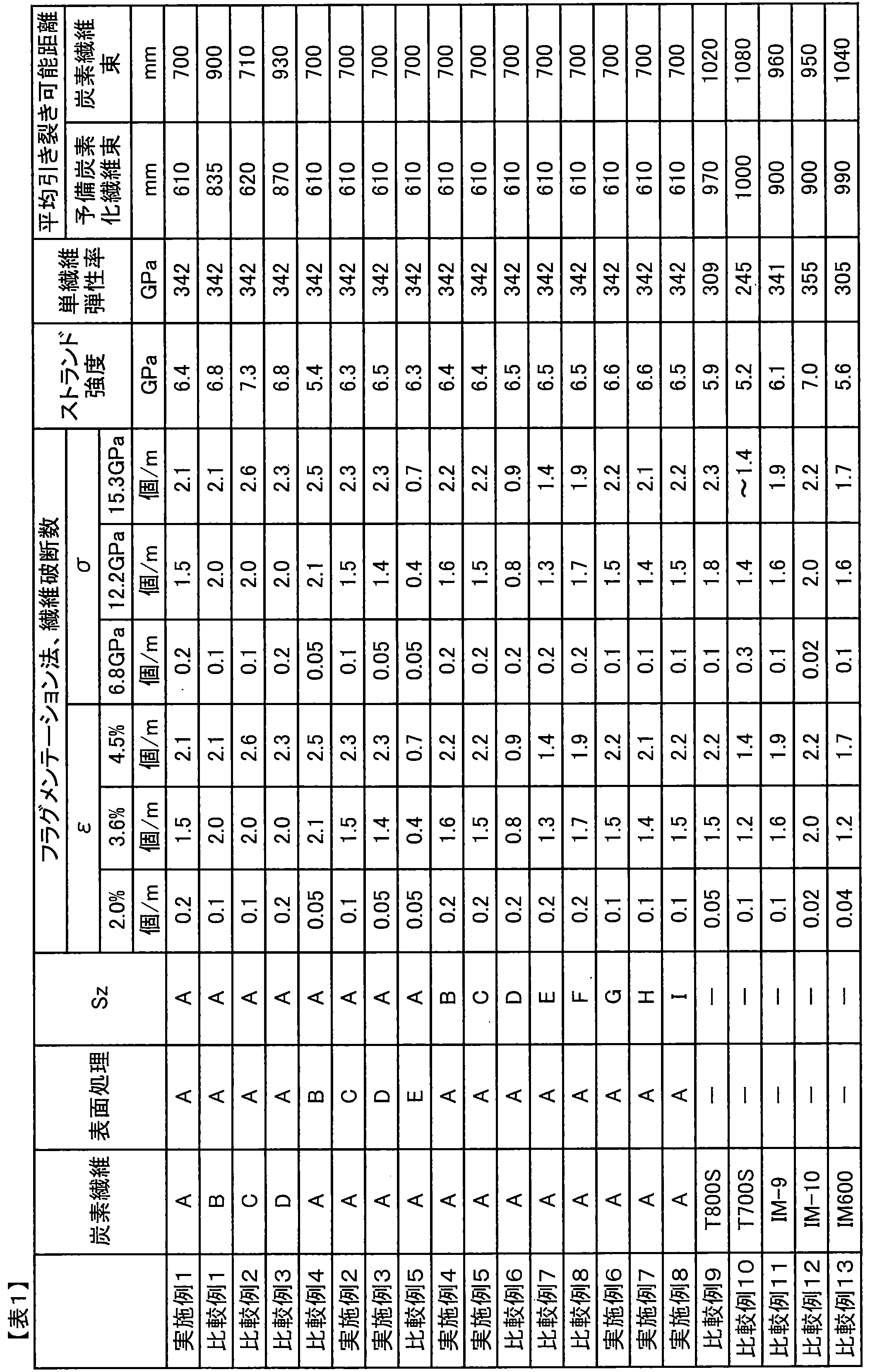

アクリロニトリル99.4mol%とイタコン酸0.6mol%からなるモノマー混合物を、ジメチルスルホキシドを溶媒とし、2,2’-アゾビスイソブチロニトリルを開始剤として溶液重合法により重合させ、ポリアクリロニトリル共重合体を製造した。製造されたポリアクリロニトリル重合体に、アンモニアガスをpH9.0になるまで吹き込み、イタコン酸を中和しつつ、アンモニウム基をポリアクリロニトリル共重合体に導入し、極限粘度が3.4(重量平均分子量で90万)である紡糸溶液を得た。得られた紡糸溶液を、30℃で、直径0.10mm、孔数6,000の紡糸口金を用い、一旦空気中に吐出し、約4mmの空間を通過させた後、0℃にコントロールした35%ジメチルスルホキシドの水溶液からなる凝固浴に導入する乾湿式紡糸法により凝固糸条を得た。この凝固糸条を、常法により水洗した後、4槽の温水浴中で第1浴から10℃ずつ昇温して、第4浴の温度を95℃とした。またこのときトータルの延伸倍率は2.5倍とした。続いて、この水浴延伸後の繊維束に対して、アミノ変性シリコーン系シリコーン油剤を付与し、160℃の加熱ローラーを用いて、乾燥緻密化処理を行い、2糸条を合糸し、単繊維本数12000本としてから、加圧スチーム中で3.7倍延伸することにより、製糸全延伸倍率を13倍とし、その後交絡処理を行って単繊維繊度0.41dtex、単繊維本数12000本のポリアクリロニトリル前駆体繊維を得た。ここで、交絡処理とは、繊維束長手方向と流体の吹き付け方向の成す角が90°で、かつ繊維束を取り囲むように8個の噴出孔を配置し、各々の噴出孔が2孔で1組となるよう対向する位置に配置した流体吹きつけノズルを用い、流体として空気を用い、繊維束の張力が3mN/dtexの状態に調節し、かつ、流体の吐出圧力を0.35MPaに設定して行った。次に、温度250~280℃の空気中において、延伸比1.00で延伸しながら耐炎化処理し、比重1.36g/cm3の耐炎化繊維束を得た。得られた耐炎化繊維束を、温度300~800℃の窒素雰囲気中において、延伸比1.10で延伸しながら予備炭素化処理を行い、予備炭素化繊維束を得た。得られた予備炭素化繊維束を、窒素雰囲気中において、最高温度1500℃で、9.8mN/dtexの張力で炭素化処理を行い、炭素繊維を得た。 [Example 17]
A monomer mixture composed of 99.4 mol% of acrylonitrile and 0.6 mol% of itaconic acid was polymerized by a solution polymerization method using dimethyl sulfoxide as a solvent and 2,2′-azobisisobutyronitrile as an initiator, and polyacrylonitrile copolymer A coalescence was produced. Ammonia gas was blown into the produced polyacrylonitrile polymer until the pH reached 9.0, and while itaconic acid was neutralized, ammonium groups were introduced into the polyacrylonitrile copolymer, and the intrinsic viscosity was 3.4 (weight average molecular weight). A spinning solution of 900,000) was obtained. The obtained spinning solution was discharged at 30 ° C. using a spinneret having a diameter of 0.10 mm and a number of holes of 6,000, once passed through the space of about 4 mm, and then controlled at 0 ° C. 35 A coagulated yarn was obtained by a dry-wet spinning method introduced into a coagulation bath consisting of an aqueous solution of% dimethyl sulfoxide. The coagulated yarn was washed with water by a conventional method, and then the temperature of the fourth bath was set to 95 ° C. by raising the temperature from the first bath by 10 ° C. in 4 warm water baths. At this time, the total draw ratio was 2.5 times. Subsequently, an amino-modified silicone-based silicone oil agent is applied to the fiber bundle after stretching in the water bath, a drying densification treatment is performed using a heating roller at 160 ° C., two yarns are combined, and a single fiber After the number of yarns is 12,000, the yarn is stretched 3.7 times in pressurized steam to increase the total draw ratio of yarn production to 13 times, and then entangled to give a single fiber fineness of 0.41 dtex and a single fiber of 12,000 polyacrylonitrile. Precursor fibers were obtained. Here, the entanglement treatment means that the angle formed by the fiber bundle longitudinal direction and the fluid blowing direction is 90 °, and eight ejection holes are arranged so as to surround the fiber bundle, and each ejection hole is composed of two holes. Using fluid blowing nozzles arranged at opposing positions so as to form a pair, using air as the fluid, adjusting the tension of the fiber bundle to 3 mN / dtex, and setting the fluid discharge pressure to 0.35 MPa I went. Next, flameproofing treatment was performed in air at a temperature of 250 to 280 ° C. while drawing at a draw ratio of 1.00, to obtain a flameproofed fiber bundle having a specific gravity of 1.36 g / cm 3 . The obtained flame-resistant fiber bundle was subjected to a pre-carbonization treatment while being drawn at a draw ratio of 1.10 in a nitrogen atmosphere at a temperature of 300 to 800 ° C. to obtain a pre-carbonized fiber bundle. The obtained pre-carbonized fiber bundle was carbonized at a maximum temperature of 1500 ° C. and a tension of 9.8 mN / dtex in a nitrogen atmosphere to obtain carbon fibers.
ポリアクリロニトリル前駆体繊維の単繊維繊度が0.26dtexになるように紡糸溶液の吐出量を調整した以外は実施例17と同様にしてサイジング剤塗布炭素繊維束を得た。得られたサイジング剤塗布炭素繊維束の特性、OHT試験結果を表3にまとめた。 [Example 18]
A sizing agent-coated carbon fiber bundle was obtained in the same manner as in Example 17 except that the amount of spinning solution discharged was adjusted so that the single fiber fineness of the polyacrylonitrile precursor fiber was 0.26 dtex. Table 3 shows the characteristics of the obtained sizing agent-coated carbon fiber bundle and the OHT test results.
ポリアクリロニトリル前駆体繊維の単繊維繊度が0.14dtexになるように紡糸溶液の吐出量を調整した以外は実施例17と同様にしてサイジング剤塗布炭素繊維束を得た。得られたサイジング剤塗布炭素繊維束の特性、OHT試験結果を表3にまとめた。 [Example 19]
A sizing agent-coated carbon fiber bundle was obtained in the same manner as in Example 17 except that the discharge amount of the spinning solution was adjusted so that the single fiber fineness of the polyacrylonitrile precursor fiber was 0.14 dtex. Table 3 shows the characteristics of the obtained sizing agent-coated carbon fiber bundle and the OHT test results.
ポリアクリロニトリル前駆体繊維の単繊維繊度が0.60dtexになるように紡糸溶液の吐出量を調整した以外は実施例17と同様にしてサイジング剤塗布炭素繊維束を得た。得られたサイジング剤塗布炭素繊維束の特性、OHT試験結果を表3にまとめた。 [Example 20]
A sizing agent-coated carbon fiber bundle was obtained in the same manner as in Example 17 except that the discharge amount of the spinning solution was adjusted so that the single fiber fineness of the polyacrylonitrile precursor fiber was 0.60 dtex. Table 3 shows the characteristics of the obtained sizing agent-coated carbon fiber bundle and the OHT test results.
アクリロニトリル99.5mol%とイタコン酸0.5mol%からなるモノマー混合物を、ジメチルスルホキシドを溶媒とし、2,2’-アゾビスイソブチロニトリルを開始剤として溶液重合法により重合させ、重量平均分子量70万、Mz/Mwが1.8のポリアクリロニトリル共重合体を製造した。製造されたポリアクリロニトリル重合体に、アンモニアガスをpH8.5になるまで吹き込み、重合体濃度が15質量%になるように調整して、紡糸溶液を得た。得られた紡糸溶液を、40℃で、直径0.15mm、孔数6,000の紡糸口金を用い、一旦空気中に吐出し、約4mmの空間を通過させた後、3℃にコントロールした35%ジメチルスルホキシドの水溶液からなる凝固浴に導入する乾湿式紡糸法により凝固糸条を得た。この凝固糸条を、常法により水洗した後、2槽の温水浴中で、3.5倍の延伸を行った。続いて、この水浴延伸後の繊維束に対して、アミノ変性シリコーン系シリコーン油剤を付与し、160℃の加熱ローラーを用いて、乾燥緻密化処理を行った。続いて、2糸条を合糸し、単繊維本数12000本としてから、加圧スチーム中で3.7倍延伸することにより、製糸全延伸倍率を13倍とし、その後交絡処理を行って単繊維繊度0.70dtex、単繊維本数12000本のポリアクリロニトリル前駆体繊維を得た。ここで、交絡処理とは、繊維束長手方向と流体の吹き付け方向の成す角が90°で、かつ繊維束を取り囲むように8個の噴出孔を配置し、各々の噴出孔が2孔で1組となるよう対向する位置に配置した流体吹きつけノズルを用い、流体として空気を用い、繊維束の張力が3mN/dtexの状態に調節し、かつ、流体の吐出圧力を0.35MPaに設定して行った。次に、温度240~260℃の空気中において、延伸比1で延伸しながら耐炎化処理し、比重1.35~1.36の耐炎化繊維束を得た。得られた耐炎化繊維束を、温度300~800℃の窒素雰囲気中において、延伸比1.15で延伸しながら予備炭素化処理を行い、予備炭素化繊維束を得た。得られた予備炭素化繊維束を、窒素雰囲気中において、最高温度1500℃で、5.5mN/dtexの張力で炭素化処理を行い、炭素繊維を得た。 [Example 21]
A monomer mixture composed of 99.5 mol% of acrylonitrile and 0.5 mol% of itaconic acid was polymerized by a solution polymerization method using dimethyl sulfoxide as a solvent and 2,2′-azobisisobutyronitrile as an initiator, and a weight average molecular weight of 70 A polyacrylonitrile copolymer having a Mz / Mw of 1.8 was produced. Ammonia gas was blown into the manufactured polyacrylonitrile polymer until the pH reached 8.5, and the polymer concentration was adjusted to 15% by mass to obtain a spinning solution. The obtained spinning solution was discharged into the air once at 40 ° C. using a spinneret having a diameter of 0.15 mm and a hole number of 6,000, passed through a space of about 4 mm, and then controlled at 3 ° C. 35 A coagulated yarn was obtained by a dry-wet spinning method introduced into a coagulation bath consisting of an aqueous solution of% dimethyl sulfoxide. The coagulated yarn was washed with water by a conventional method, and then stretched 3.5 times in two warm water baths. Subsequently, an amino-modified silicone-based silicone oil was applied to the fiber bundle after stretching in the water bath, and a dry densification treatment was performed using a 160 ° C. heating roller. Subsequently, the two yarns are combined and the number of single fibers is set to 12,000, and then drawn in pressure steam to 3.7 times to make the total drawing ratio of yarn making 13 times, and then the entanglement treatment is performed to obtain single fibers. A polyacrylonitrile precursor fiber having a fineness of 0.70 dtex and a number of single fibers of 12,000 was obtained. Here, the entanglement treatment means that the angle formed by the fiber bundle longitudinal direction and the fluid blowing direction is 90 °, and eight ejection holes are arranged so as to surround the fiber bundle, and each ejection hole is composed of two holes. Using fluid blowing nozzles arranged at opposing positions so as to form a pair, using air as the fluid, adjusting the tension of the fiber bundle to 3 mN / dtex, and setting the fluid discharge pressure to 0.35 MPa I went. Next, flameproofing treatment was performed in air at a temperature of 240 to 260 ° C. while stretching at a stretch ratio of 1, and a flameproof fiber bundle having a specific gravity of 1.35 to 1.36 was obtained. The obtained flame-resistant fiber bundle was subjected to a preliminary carbonization treatment while being drawn at a draw ratio of 1.15 in a nitrogen atmosphere at a temperature of 300 to 800 ° C. to obtain a pre-carbonized fiber bundle. The obtained pre-carbonized fiber bundle was carbonized at a maximum temperature of 1500 ° C. and a tension of 5.5 mN / dtex in a nitrogen atmosphere to obtain carbon fibers.
ポリアクリロニトリル前駆体繊維の単繊維繊度が0.62dtexになるように紡糸溶液の吐出量を調整した以外は実施例21と同様にしてサイジング剤塗布炭素繊維束を得た。得られたサイジング剤塗布炭素繊維束の特性、OHT試験結果を表3にまとめた。 [Example 22]
A sizing agent-coated carbon fiber bundle was obtained in the same manner as in Example 21, except that the discharge amount of the spinning solution was adjusted so that the single fiber fineness of the polyacrylonitrile precursor fiber was 0.62 dtex. Table 3 shows the characteristics of the obtained sizing agent-coated carbon fiber bundle and the OHT test results.
サイジング剤について、“jER(登録商標)”828(三菱化学(株)製)、“jER(登録商標)”1001(三菱化学(株)製)、ビスフェノールAのEO2モル付加物2モルとマレイン酸1.5モルおよびセバチン酸0.5モルの縮合物、“デナコール(登録商標)”EX-521(ナガセケムテックス(株)製)の量を10質量部:10質量部:20質量部:50質量部から22.5質量部:22.5質量部:45質量部:0に変更した以外は実施例17と同様にしてサイジング剤塗布炭素繊維束を得た。得られたサイジング剤塗布炭素繊維束の特性、OHT試験結果を表3にまとめた。 [Comparative Example 27]
Regarding the sizing agent, “jER (registered trademark)” 828 (manufactured by Mitsubishi Chemical Corporation), “jER (registered trademark)” 1001 (manufactured by Mitsubishi Chemical Corporation), 2 mol of EO2 mol adduct of bisphenol A and maleic acid The amount of a 1.5 mol and 0.5 mol sebacic acid condensate, “Denacol (registered trademark)” EX-521 (manufactured by Nagase ChemteX Corp.) was 10 parts by mass: 10 parts by mass: 20 parts by mass: 50 parts by mass. A sizing agent-coated carbon fiber bundle was obtained in the same manner as in Example 17 except that the mass was changed to 22.5 parts by mass: 22.5 parts by mass: 45 parts by mass: 0. Table 3 shows the characteristics of the obtained sizing agent-coated carbon fiber bundle and the OHT test results.
ポリアクリロニトリル前駆体繊維の単繊維繊度が0.14dtexになるように紡糸溶液の吐出量を調整した以外は比較例27と同様にしてサイジング剤塗布炭素繊維束を得た。得られたサイジング剤塗布炭素繊維束の特性、OHT試験結果を表3にまとめた。 [Comparative Example 28]
A sizing agent-coated carbon fiber bundle was obtained in the same manner as in Comparative Example 27 except that the discharge amount of the spinning solution was adjusted so that the single fiber fineness of the polyacrylonitrile precursor fiber was 0.14 dtex. Table 3 shows the characteristics of the obtained sizing agent-coated carbon fiber bundle and the OHT test results.
ポリアクリロニトリル前駆体繊維の製造工程において、交絡処理を行わない以外は実施例19と同様にしてサイジング剤塗布炭素繊維束を得た。得られたサイジング剤塗布炭素繊維束の特性、OHT試験結果を表3にまとめた。 [Comparative Example 29]
In the production process of the polyacrylonitrile precursor fiber, a sizing agent-coated carbon fiber bundle was obtained in the same manner as in Example 19 except that the entanglement treatment was not performed. Table 3 shows the characteristics of the obtained sizing agent-coated carbon fiber bundle and the OHT test results.
ポリアクリロニトリル前駆体繊維の製造工程において、交絡処理を行わない以外は実施例19と同様にしてサイジング剤塗布炭素繊維束を得た。得られたサイジング剤塗布炭素繊維束の特性、OHT試験結果を表3にまとめた。 [Comparative Example 30]
In the production process of the polyacrylonitrile precursor fiber, a sizing agent-coated carbon fiber bundle was obtained in the same manner as in Example 19 except that the entanglement treatment was not performed. Table 3 shows the characteristics of the obtained sizing agent-coated carbon fiber bundle and the OHT test results.
市販されている“Torayca(登録商標)”T800S(東レ社製)を用いて解析を行った。炭素繊維束の特性を表3にまとめた。 [Comparative Example 31]
Analysis was performed using a commercially available “Torayca (registered trademark)” T800S (manufactured by Toray Industries, Inc.). The properties of the carbon fiber bundle are summarized in Table 3.
市販されている“TENAX(登録商標) ”IM600(東邦テナックス社製)を用いて解析を行った。炭素繊維束の特性を表3にまとめた。 [Comparative Example 32]
Analysis was performed using a commercially available “TENAX (registered trademark)” IM600 (manufactured by Toho Tenax Co., Ltd.). The properties of the carbon fiber bundle are summarized in Table 3.

アクリロニトリル99.5mol%とイタコン酸0.5mol%からなるモノマー混合物を、ジメチルスルホキシドを溶媒とし、2,2’-アゾビスイソブチロニトリルを開始剤として溶液重合法により重合させ、ポリアクリロニトリル共重合体を製造した。製造されたポリアクリロニトリル重合体に、アンモニアガスをpH8.5になるまで吹き込み、イタコン酸を中和しつつ、アンモニウム基をポリアクリロニトリル共重合体に導入し、紡糸原液を得た。得られた紡糸原液を、40℃で、直径0.15mm、孔数6,000の紡糸口金を用い、一旦空気中に吐出し、約4mmの空間を通過させた後、3℃にコントロールした35%ジメチルスルホキシドの水溶液からなる凝固浴に導入する乾湿式紡糸法により凝固糸条を得た。この凝固糸条を、常法により水洗した後、2槽の温水浴中で、3.5倍の延伸を行った。続いて、この水浴延伸後の繊維束に対して、流体として空気を用い、表4記載の条件で流体交絡処理を行った後に、アミノ変性シリコーン系シリコーン油剤を付与し、160℃の加熱ローラーを用いて、乾燥緻密化処理を行い、次いで、加圧スチーム中で3.7倍延伸することにより、製糸全延伸倍率を13倍とし、単繊維繊度0.7dtex、単繊維本数6000本のポリアクリロニトリル前駆体繊維束を得た。次に、得られたアクリル繊維を2本合糸し、単繊維本数12000本とし、温度240~260℃の空気中において、延伸比1で延伸しながら耐炎化処理し、比重1.35~1.36の耐炎化繊維束を得た。得られた耐炎化繊維束を、温度300~800℃の窒素雰囲気中において、延伸比1.15で延伸しながら予備炭素化処理を行い、予備炭素化繊維束を得た。得られた予備炭素化繊維束を、窒素雰囲気中において、最高温度1500℃で、表5記載の張力で炭素化処理を行い、炭素繊維を得た。得られた炭素繊維を、濃度0.1モル/lの硫酸水溶液を電解液として電解表面処理し、水洗、150℃で乾燥した後、サイジング剤を付与し、良好な品位であり実質的に無撚りのサイジング剤塗布炭素繊維束を得た。製造条件、得られた炭素繊維束の特性などを表4、5にまとめた。 [Example 23]
A monomer mixture composed of 99.5 mol% of acrylonitrile and 0.5 mol% of itaconic acid was polymerized by a solution polymerization method using dimethyl sulfoxide as a solvent and 2,2′-azobisisobutyronitrile as an initiator, and polyacrylonitrile copolymer A coalescence was produced. Ammonia gas was blown into the produced polyacrylonitrile polymer until the pH reached 8.5, and ammonium groups were introduced into the polyacrylonitrile copolymer while neutralizing itaconic acid to obtain a spinning dope. The obtained stock solution for spinning was discharged at 40 ° C. using a spinneret having a diameter of 0.15 mm and a number of holes of 6,000, once passed through the space of about 4 mm, and then controlled at 3 ° C. 35 A coagulated yarn was obtained by a dry-wet spinning method introduced into a coagulation bath consisting of an aqueous solution of% dimethyl sulfoxide. The coagulated yarn was washed with water by a conventional method, and then stretched 3.5 times in two warm water baths. Subsequently, the fiber bundle after the water bath stretching was subjected to fluid entanglement treatment using air as a fluid under the conditions shown in Table 4, and then an amino-modified silicone-based silicone oil was applied, and a 160 ° C. heating roller was attached. And then subjected to a dry densification treatment, and then stretched by 3.7 times in pressurized steam, so that the total draw ratio of yarn production is 13 times, the single fiber fineness is 0.7 dtex, and the number of single fibers is 6000 polyacrylonitrile. A precursor fiber bundle was obtained. Next, two acrylic fibers obtained were combined to make 12,000 single fibers, and subjected to a flame resistance treatment in air at a temperature of 240 to 260 ° C. while drawing at a draw ratio of 1, and a specific gravity of 1.35 to 1 .36 flame-resistant fiber bundles were obtained. The obtained flame-resistant fiber bundle was subjected to a preliminary carbonization treatment while being drawn at a draw ratio of 1.15 in a nitrogen atmosphere at a temperature of 300 to 800 ° C. to obtain a pre-carbonized fiber bundle. The obtained pre-carbonized fiber bundle was carbonized in a nitrogen atmosphere at a maximum temperature of 1500 ° C. and with the tensions shown in Table 5 to obtain carbon fibers. The obtained carbon fiber was subjected to electrolytic surface treatment using an aqueous sulfuric acid solution having a concentration of 0.1 mol / l as an electrolytic solution, washed with water and dried at 150 ° C., and then provided with a sizing agent. A twisted sizing agent-coated carbon fiber bundle was obtained. Production conditions, characteristics of the obtained carbon fiber bundle, etc. are summarized in Tables 4 and 5.
炭素化処理における炭素化張力を14.7mN/dtexに変更した以外は、実施例23と同様にしてサイジング剤塗布炭素繊維束を得た。得られた炭素繊維束の単繊維破断数は少なく品位が良好であり、ストランド弾性率は364GPaに向上した。製造条件、得られた炭素繊維束の特性などを表4、5にまとめた。 [Example 24]
A sizing agent-coated carbon fiber bundle was obtained in the same manner as in Example 23 except that the carbonization tension in the carbonization treatment was changed to 14.7 mN / dtex. The obtained carbon fiber bundle had few single fiber breaks and good quality, and the strand elastic modulus was improved to 364 GPa. Production conditions, characteristics of the obtained carbon fiber bundle, etc. are summarized in Tables 4 and 5.
炭素化処理における炭素化張力を18.6mN/dtexに変更した以外は、実施例23と同様にしてサイジング剤塗布炭素繊維束を得た。得られた炭素繊維束の単繊維破断数は少なく品位が良好であり、ストランド弾性率は378GPaに向上した。製造条件、得られた炭素繊維束の特性などを表4、5にまとめた。 [Example 25]
A sizing agent-coated carbon fiber bundle was obtained in the same manner as in Example 23 except that the carbonization tension in the carbonization treatment was changed to 18.6 mN / dtex. The obtained carbon fiber bundle had few single fiber breaks and good quality, and the strand elastic modulus was improved to 378 GPa. Production conditions, characteristics of the obtained carbon fiber bundle, etc. are summarized in Tables 4 and 5.
ポリアクリロニトリル前駆体繊維の流体交絡処理を行わなかった以外は、実施例23と同様にしてサイジング剤塗布炭素繊維束を得た。得られた炭素繊維束の単繊維破断数は増加して品位は大きく低下し、ストランド強度は5500MPaに低下した。製造条件、得られた炭素繊維束の特性などを表4、5にまとめた。 [Comparative Example 33]
A sizing agent-coated carbon fiber bundle was obtained in the same manner as in Example 23, except that the fluid entanglement treatment of the polyacrylonitrile precursor fiber was not performed. The number of single fiber breaks in the obtained carbon fiber bundle was increased, the quality was greatly reduced, and the strand strength was reduced to 5500 MPa. Production conditions, characteristics of the obtained carbon fiber bundle, etc. are summarized in Tables 4 and 5.
アクリロニトリル99.5mol%とイタコン酸0.5mol%からなるモノマー混合物を、ジメチルスルホキシドを溶媒とし、2,2’-アゾビスイソブチロニトリルを開始剤として溶液重合法により重合させ、ポリアクリロニトリル共重合体を製造した。製造されたポリアクリロニトリル重合体に、アンモニアガスをpH8.5になるまで吹き込み、イタコン酸を中和しつつ、アンモニウム基をポリアクリロニトリル共重合体に導入し、紡糸原液を得た。得られた紡糸原液を、40℃で、直径0.15mm、孔数6000の紡糸口金を用い、一旦空気中に吐出し、約4mmの空間を通過させた後、3℃にコントロールした35%ジメチルスルホキシドの水溶液からなる凝固浴に導入する乾湿式紡糸法により凝固糸条を得た。この凝固糸条を、常法により水洗した後、2槽の温水浴中で、3.5倍の延伸を行った後に、アミノ変性シリコーン系シリコーン油剤を付与し、160℃の加熱ローラーを用いて、乾燥緻密化処理を行い、次いで、加圧スチーム中で3.7倍延伸することにより、製糸全延伸倍率を13倍とし、単繊維繊度0.7dtex、単繊維本数6000本のポリアクリロニトリル前駆体繊維束を得た。続いて、このポリアクリロニトリル前駆体繊維束に対して、流体として空気を用い、表4記載の条件で流体交絡処理を行った後に、12000本に合糸し、実施例23と同様にしてサイジング剤塗布炭素繊維束を得た。得られた炭素繊維束の単繊維破断数は増加して品位は大きく低下し、ストランド強度は5850MPaに低下した。製造条件、得られた炭素繊維束の特性などを表4、5にまとめた。 [Comparative Example 34]
A monomer mixture composed of 99.5 mol% of acrylonitrile and 0.5 mol% of itaconic acid was polymerized by a solution polymerization method using dimethyl sulfoxide as a solvent and 2,2′-azobisisobutyronitrile as an initiator, and polyacrylonitrile copolymer A coalescence was produced. Ammonia gas was blown into the produced polyacrylonitrile polymer until the pH reached 8.5, and ammonium groups were introduced into the polyacrylonitrile copolymer while neutralizing itaconic acid to obtain a spinning dope. The obtained stock solution for spinning was discharged at 40 ° C. using a spinneret having a diameter of 0.15 mm and a hole number of 6000, once passed through the space of about 4 mm, and then 35% dimethyl controlled at 3 ° C. A coagulated yarn was obtained by a dry and wet spinning method introduced into a coagulation bath made of an aqueous solution of sulfoxide. The coagulated yarn is washed with water by a conventional method, and then stretched 3.5 times in two warm water baths. Then, an amino-modified silicone-based silicone oil agent is applied, and a 160 ° C. heating roller is used. The polyacrylonitrile precursor having a single fiber fineness of 0.7 dtex and a single fiber number of 6000 is obtained by performing a drying densification treatment and then stretching by 3.7 times in pressurized steam to increase the total drawing ratio of yarns to 13 times. A fiber bundle was obtained. Subsequently, the polyacrylonitrile precursor fiber bundle was subjected to fluid entanglement treatment under the conditions shown in Table 4 using air as a fluid, and then combined into 12,000 yarns, and the sizing agent in the same manner as in Example 23. A coated carbon fiber bundle was obtained. The number of single fiber breaks in the obtained carbon fiber bundle increased, the quality was greatly reduced, and the strand strength was reduced to 5850 MPa. Production conditions, characteristics of the obtained carbon fiber bundle, etc. are summarized in Tables 4 and 5.
炭素化処理における炭素化張力を14.7mN/dtexに変更した以外は、比較例34と同様にしてサイジング剤塗布炭素繊維束を得ようとしたが、炭素化工程で糸切れが多発して、良好な品位の炭素繊維束を得ることはできなかった。製造条件、得られた炭素繊維束の特性などを表4、5にまとめた。 [Comparative Example 35]
Except for changing the carbonization tension in the carbonization treatment to 14.7 mN / dtex, an attempt was made to obtain a sizing agent-coated carbon fiber bundle in the same manner as in Comparative Example 34. However, yarn breakage frequently occurred in the carbonization process, A good quality carbon fiber bundle could not be obtained. Production conditions, characteristics of the obtained carbon fiber bundle, etc. are summarized in Tables 4 and 5.
アクリロニトリル99.5mol%とイタコン酸0.5mol%からなるモノマー混合物を、ジメチルスルホキシドを溶媒とし、2,2’-アゾビスイソブチロニトリルを開始剤として溶液重合法により重合させ、ポリアクリロニトリル共重合体を製造した。製造されたポリアクリロニトリル重合体に、アンモニアガスをpH8.5になるまで吹き込み、イタコン酸を中和しつつ、アンモニウム基をポリアクリロニトリル共重合体に導入し、紡糸原液を得た。得られた紡糸原液を、40℃で、直径0.15mm、孔数6000の紡糸口金を用い、一旦空気中に吐出し、約4mmの空間を通過させた後、3℃にコントロールした35%ジメチルスルホキシドの水溶液からなる凝固浴に導入する乾湿式紡糸法により凝固糸条を得た。この凝固糸条を、常法により水洗した後、2槽の温水浴中で、3.5倍の延伸を行った後に、アミノ変性シリコーン系シリコーン油剤を付与し、160℃の加熱ローラーを用いて、乾燥緻密化処理を行い、次いで、加圧スチーム中で3.7倍延伸することにより、製糸全延伸倍率を13倍とし、単繊維繊度0.7dtex、単繊維本数6000本のポリアクリロニトリル前駆体繊維束を得た。次に、得られたアクリル繊維を温度240~260℃の空気中において、延伸比1で延伸しながら耐炎化処理し、比重1.35~1.36の耐炎化繊維束を得た。得られた耐炎化繊維束を、温度300~800℃の窒素雰囲気中において、延伸比1.15で延伸しながら予備炭素化処理を行い、流体として空気を用い、表4記載の条件で流体交絡処理を行った後に12000本に合糸し、予備炭素化繊維束を得た。得られた予備炭素化繊維束を、窒素雰囲気中において、最高温度1500℃で表4記載の張力で炭素化処理を行い、炭素繊維を得た。得られた炭素繊維を、濃度0.1モル/lの硫酸水溶液を電解液として電解表面処理し、水洗、150℃で乾燥した後、サイジング剤を付与し、良好な品位であり実質的に無撚りのサイジング剤塗布炭素繊維束を得た。製造条件、得られた炭素繊維束の特性などを表4、5にまとめた。 [Example 26]
A monomer mixture composed of 99.5 mol% of acrylonitrile and 0.5 mol% of itaconic acid was polymerized by a solution polymerization method using dimethyl sulfoxide as a solvent and 2,2′-azobisisobutyronitrile as an initiator, and polyacrylonitrile copolymer A coalescence was produced. Ammonia gas was blown into the produced polyacrylonitrile polymer until the pH reached 8.5, and ammonium groups were introduced into the polyacrylonitrile copolymer while neutralizing itaconic acid to obtain a spinning dope. The obtained stock solution for spinning was discharged at 40 ° C. using a spinneret having a diameter of 0.15 mm and a hole number of 6000, once passed through the space of about 4 mm, and then 35% dimethyl controlled at 3 ° C. A coagulated yarn was obtained by a dry and wet spinning method introduced into a coagulation bath made of an aqueous solution of sulfoxide. The coagulated yarn is washed with water by a conventional method, and then stretched 3.5 times in two warm water baths. Then, an amino-modified silicone-based silicone oil agent is applied, and a 160 ° C. heating roller is used. The polyacrylonitrile precursor having a single fiber fineness of 0.7 dtex and a single fiber number of 6000 is obtained by performing a drying densification treatment and then stretching by 3.7 times in pressurized steam to increase the total drawing ratio of yarns to 13 times. A fiber bundle was obtained. Next, the obtained acrylic fiber was flameproofed in air at a temperature of 240 to 260 ° C. while being stretched at a stretch ratio of 1, to obtain a flameproof fiber bundle having a specific gravity of 1.35 to 1.36. The obtained flame-resistant fiber bundle was subjected to a preliminary carbonization treatment while being drawn at a draw ratio of 1.15 in a nitrogen atmosphere at a temperature of 300 to 800 ° C., and fluid was entangled under the conditions shown in Table 4 using air as a fluid. After the treatment, 12,000 yarns were combined to obtain a pre-carbonized fiber bundle. The obtained pre-carbonized fiber bundle was carbonized at a maximum temperature of 1500 ° C. and with the tension described in Table 4 in a nitrogen atmosphere to obtain carbon fibers. The obtained carbon fiber was subjected to electrolytic surface treatment using an aqueous sulfuric acid solution having a concentration of 0.1 mol / l as an electrolytic solution, washed with water and dried at 150 ° C., and then provided with a sizing agent. A twisted sizing agent-coated carbon fiber bundle was obtained. Production conditions, characteristics of the obtained carbon fiber bundle, etc. are summarized in Tables 4 and 5.
炭素化処理における炭素化張力を14.7mN/dtexに変更した以外は、実施例26と同様にしてサイジング剤塗布炭素繊維束を得た。得られた炭素繊維束の単繊維破断数は少なく品位が良好であり、ストランド弾性率は365GPaに向上した。製造条件、得られた炭素繊維束の特性などを表4、5にまとめた。 [Example 27]
A sizing agent-coated carbon fiber bundle was obtained in the same manner as in Example 26 except that the carbonization tension in the carbonization treatment was changed to 14.7 mN / dtex. The obtained carbon fiber bundle had few single fiber breaks and good quality, and the strand elastic modulus was improved to 365 GPa. Production conditions, characteristics of the obtained carbon fiber bundle, etc. are summarized in Tables 4 and 5.
炭素化処理における炭素化張力を18.6mN/dtexに変更した以外は、実施例27と同様にしてサイジング剤塗布炭素繊維束を得ようとしたが、炭素化工程で糸切れが多発して、良好な品位の炭素繊維束を得ることはできなかった。製造条件、得られた炭素繊維束の特性などを表4、5にまとめた。 [Comparative Example 36]
Except for changing the carbonization tension in the carbonization treatment to 18.6 mN / dtex, an attempt was made to obtain a sizing agent-coated carbon fiber bundle in the same manner as in Example 27. A good quality carbon fiber bundle could not be obtained. Production conditions, characteristics of the obtained carbon fiber bundle, etc. are summarized in Tables 4 and 5.
炭素化処理における炭素化温度を2300℃に変更した以外は、実施例23と同様にしてサイジング剤塗布炭素繊維束を得た。得られた炭素繊維束の単繊維破断数は少なく品位が良好であり、ストランド弾性率は377GPaに向上したが、ストランド強度は4560MPaに低下した。製造条件、得られた炭素繊維束の特性などを表4、5にまとめた。 [Comparative Example 37]
A sizing agent-coated carbon fiber bundle was obtained in the same manner as in Example 23 except that the carbonization temperature in the carbonization treatment was changed to 2300 ° C. The resulting carbon fiber bundle had few single fiber breaks and good quality, and the strand elastic modulus improved to 377 GPa, but the strand strength decreased to 4560 MPa. Production conditions, characteristics of the obtained carbon fiber bundle, etc. are summarized in Tables 4 and 5.
流体として空気を用い、表4記載の条件で流体交絡処理を行い、炭素化処理における炭素化張力を19.1mN/dtexに変更した以外は、実施例23と同様にしてサイジング剤塗布炭素繊維束を得た。得られた炭素繊維束の単繊維破断数は若干増加して品位はやや低下し、ストランド弾性率は384GPaに向上したが、ストランド強度は5900MPaとやや低下した。製造条件、得られた炭素繊維束の特性などを表4、5にまとめた。 [Example 28]
Sizing agent-coated carbon fiber bundles were used in the same manner as in Example 23, except that air was used as the fluid, fluid entanglement treatment was performed under the conditions described in Table 4, and the carbonization tension in the carbonization treatment was changed to 19.1 mN / dtex. Got. The number of single fiber breaks in the obtained carbon fiber bundle was slightly increased, the quality was slightly lowered, and the strand elastic modulus was improved to 384 GPa, but the strand strength was slightly lowered to 5900 MPa. Production conditions, characteristics of the obtained carbon fiber bundle, etc. are summarized in Tables 4 and 5.
流体として空気を用い、表4記載の条件で流体交絡処理を行い、炭素化処理における炭素化張力を19.5mN/dtexに変更した以外は、実施例23と同様にしてサイジング剤塗布炭素繊維束を得た。得られた炭素繊維束の単繊維破断数は若干増加して品位はやや低下し、ストランド弾性率は386GPaに向上したが、ストランド強度は5900MPaとやや低下した。製造条件、得られた炭素繊維束の特性などを表4、5にまとめた。 [Example 29]
Sizing agent-coated carbon fiber bundles were used in the same manner as in Example 23, except that air was used as the fluid, fluid entanglement treatment was performed under the conditions shown in Table 4, and the carbonization tension in the carbonization treatment was changed to 19.5 mN / dtex. Got. The number of single fiber breaks in the obtained carbon fiber bundle was slightly increased, the quality was slightly lowered, and the strand elastic modulus was improved to 386 GPa, but the strand strength was slightly lowered to 5900 MPa. Production conditions, characteristics of the obtained carbon fiber bundle, etc. are summarized in Tables 4 and 5.
流体交絡処理時のフィラメント数を12000本に変更した以外は、実施例23と同様にしてサイジング剤塗布炭素繊維束を得た。得られた炭素繊維束の単繊維破断数は若干増加した。製造条件、得られた炭素繊維束の特性などを表4、5にまとめた。 [Example 30]
A sizing agent-coated carbon fiber bundle was obtained in the same manner as in Example 23 except that the number of filaments during the fluid entanglement treatment was changed to 12,000. The number of single fiber breaks in the obtained carbon fiber bundle increased slightly. Production conditions, characteristics of the obtained carbon fiber bundle, etc. are summarized in Tables 4 and 5.
炭素化処理における炭素化張力を11.8mN/dtexに変更した以外は、実施例28と同様にしてサイジング剤塗布炭素繊維束を得た。得られた炭素繊維束の単繊維破断数は若干増加し、ストランド弾性率は351GPaに向上した。製造条件、得られた炭素繊維束の特性などを表4、5にまとめた。 [Example 31]
A sizing agent-coated carbon fiber bundle was obtained in the same manner as in Example 28 except that the carbonization tension in the carbonization treatment was changed to 11.8 mN / dtex. The number of single fiber breaks of the obtained carbon fiber bundle increased slightly, and the strand elastic modulus improved to 351 GPa. Production conditions, characteristics of the obtained carbon fiber bundle, etc. are summarized in Tables 4 and 5.
流体交絡処理時のフィラメント数を24000本に変更した以外は、実施例30と同様にしてサイジング剤塗布炭素繊維束を得た。得られた炭素繊維束の単繊維破断数は増加して品位は大きく低下し、ストランド強度は5700MPaに低下した。製造条件、得られた炭素繊維束の特性などを表4、5にまとめた。 [Comparative Example 38]
A sizing agent-coated carbon fiber bundle was obtained in the same manner as in Example 30, except that the number of filaments during the fluid entanglement treatment was changed to 24,000. The number of single fiber breaks in the obtained carbon fiber bundle increased, the quality was greatly reduced, and the strand strength was reduced to 5700 MPa. Production conditions, characteristics of the obtained carbon fiber bundle, etc. are summarized in Tables 4 and 5.
炭素化処理における炭素化張力を11.8mN/dtexに変更した以外は、比較例38と同様にしてサイジング剤塗布炭素繊維束を得ようとしたが、炭素化工程で糸切れが多発して、良好な品位の炭素繊維束を得ることはできなかった。製造条件、得られた炭素繊維束の特性などを表4、5にまとめた。 [Comparative Example 39]
Except for changing the carbonization tension in the carbonization treatment to 11.8 mN / dtex, an attempt was made to obtain a sizing agent-coated carbon fiber bundle in the same manner as in Comparative Example 38. A good quality carbon fiber bundle could not be obtained. Production conditions, characteristics of the obtained carbon fiber bundle, etc. are summarized in Tables 4 and 5.
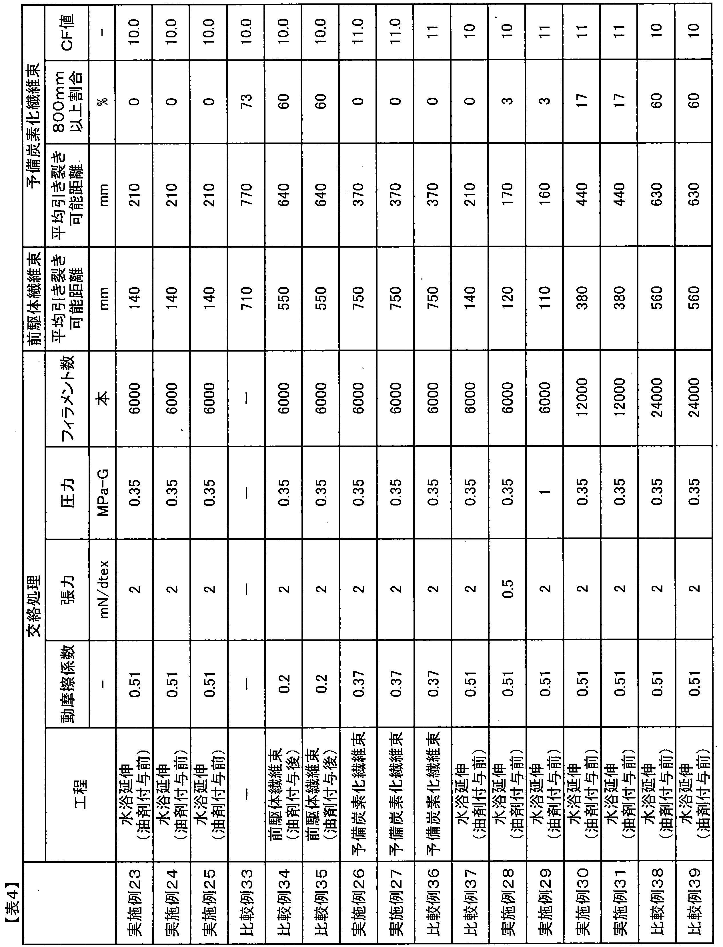
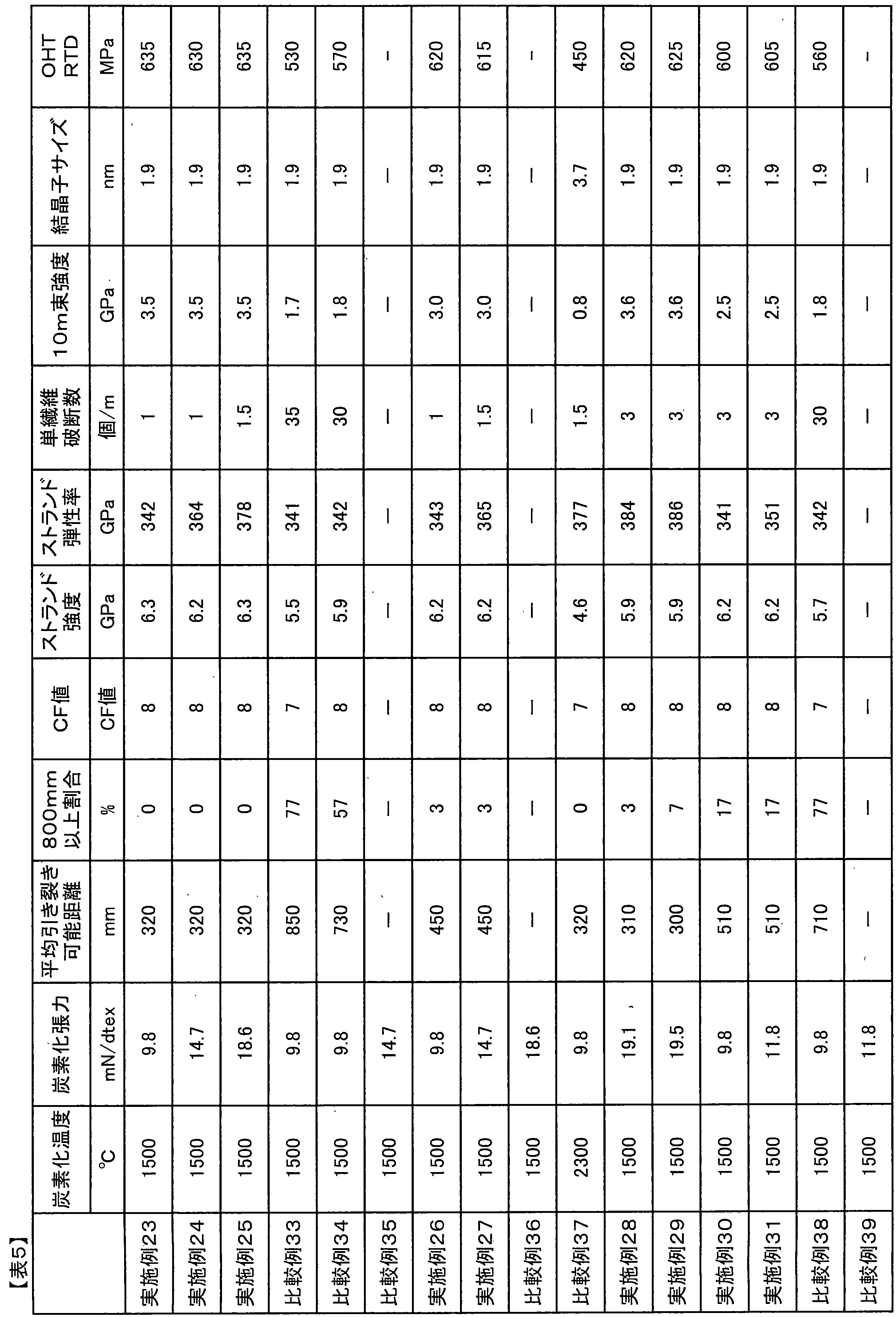
2:固定点A
3:固定点B
4:固定点C
5:交絡点
6:引き裂き可能距離 1: Fiber bundle 2: Fixed point A
3: Fixed point B
4: Fixed point C
5: Entanglement point 6: Tearable distance
Claims (14)
- 脂肪族エポキシ化合物(C)および芳香族エポキシ化合物(D)を含むサイジング剤が炭素繊維束に塗布されたサイジング剤塗布炭素繊維束であって、
前記炭素繊維束に含まれる炭素繊維は、単繊維コンポジットのフラグメンテーション法を用いて測定したときに、単繊維見掛け応力が15.3GPaのときに繊維破断数が2.0個/mm以上であり、かつ、単繊維見掛け応力が12.2GPaのときに繊維破断数が1.7個/mm以下である、サイジング剤塗布炭素繊維束。 A sizing agent-coated carbon fiber bundle in which a sizing agent containing an aliphatic epoxy compound (C) and an aromatic epoxy compound (D) is applied to a carbon fiber bundle,
The carbon fiber contained in the carbon fiber bundle has a fiber breakage number of 2.0 pieces / mm or more when the single fiber apparent stress is 15.3 GPa when measured using a fragmentation method of a single fiber composite. And the sizing agent application | coating carbon fiber bundle whose fiber breaking number is 1.7 pieces / mm or less when a single fiber apparent stress is 12.2 GPa. - 単繊維見掛け応力が12.2GPaのときの前記繊維破断数が1.3個/mm以下である、請求項1に記載のサイジング剤塗布炭素繊維束。 The sizing agent-coated carbon fiber bundle according to claim 1, wherein the fiber breakage number is 1.3 pieces / mm or less when the single fiber apparent stress is 12.2 GPa.
- 単繊維見掛け応力が12.2GPaのときの前記繊維破断数が1.0個/mm以下である、請求項1または2に記載のサイジング剤塗布炭素繊維束。 The sizing agent-coated carbon fiber bundle according to claim 1 or 2, wherein the fiber breakage number when the single fiber apparent stress is 12.2 GPa is 1.0 piece / mm or less.
- 前記炭素繊維束に含まれる炭素繊維は、単繊維コンポジットのフラグメンテーション法を用いて測定したときに、単繊維見掛け応力が10.0GPaのときに繊維破断数が0.8個/mm以下である、請求項1~3のいずれかに記載のサイジング剤塗布炭素繊維束。 The carbon fiber contained in the carbon fiber bundle has a fiber breakage number of 0.8 pieces / mm or less when the single fiber apparent stress is 10.0 GPa when measured using a fragmentation method of a single fiber composite. The sizing agent-coated carbon fiber bundle according to any one of claims 1 to 3.
- 前記炭素繊維に塗布されたサイジング剤表面を、X線光電子分光法によって光電子脱出角度15°で測定したときに得られる、C1s内殻スペクトルの(a)結合エネルギー284.6eVの成分の高さと、(b)結合エネルギー286.1eVの成分の高さとの比率(a)/(b)が0.50~0.90である、請求項1~4のいずれかに記載のサイジング剤塗布炭素繊維束。 The height of the component of (a) binding energy 284.6 eV in the C1s inner shell spectrum obtained when the surface of the sizing agent applied to the carbon fiber is measured by X-ray photoelectron spectroscopy at a photoelectron escape angle of 15 °, The sizing agent-coated carbon fiber bundle according to any one of claims 1 to 4, wherein (b) the ratio (a) / (b) to the height of the component having a binding energy of 286.1 eV is 0.50 to 0.90. .
- 平均引き裂き可能距離が300~710mmであり、実質的に無撚りの、請求項1~5のいずれかに記載のサイジング剤塗布炭素繊維束。 The sizing agent-coated carbon fiber bundle according to any one of claims 1 to 5, which has an average tearable distance of 300 to 710 mm and is substantially untwisted.
- 前記炭素繊維束の引き裂き可能距離の測定を行った際に、引き裂き可能距離が800mm以上の割合が15%以下である、請求項6に記載のサイジング剤塗布炭素繊維束。 The sizing agent-coated carbon fiber bundle according to claim 6, wherein a ratio of the tearable distance of 800 mm or more is 15% or less when the tearable distance of the carbon fiber bundle is measured.
- 炭素繊維束にサイジング剤が塗布されたサイジング剤塗布炭素繊維束であって、前記炭素繊維束に含まれる炭素繊維は、単繊維コンポジットのフラグメンテーション法を用いて測定したときに、単繊維見掛け応力が15.3GPaのときに繊維破断数が2.0個/mm以上であり、かつ、単繊維見掛け応力が12.2GPaのときに繊維破断数が1.3個/mm以下であるサイジング剤塗布炭素繊維束。 A sizing agent-coated carbon fiber bundle in which a sizing agent is applied to a carbon fiber bundle, and the carbon fiber contained in the carbon fiber bundle has a single fiber apparent stress when measured using a fragmentation method of a single fiber composite. Sizing agent-coated carbon having a fiber breakage number of 2.0 / mm or more at 15.3 GPa and a fiber breakage of 1.3 / mm or less when the single fiber apparent stress is 12.2 GPa Fiber bundle.
- 前記炭素繊維束に含まれる炭素繊維は、単繊維コンポジットのフラグメンテーション法を用いて測定したときに、単繊維見掛け応力が10.0GPaのときに繊維破断数が0.8個/mm以下である、請求項8に記載のサイジング剤塗布炭素繊維束。 The carbon fiber contained in the carbon fiber bundle has a fiber breakage number of 0.8 pieces / mm or less when the single fiber apparent stress is 10.0 GPa when measured using a fragmentation method of a single fiber composite. A sizing agent-coated carbon fiber bundle according to claim 8.
- 前記炭素繊維に塗布されたサイジング剤表面を、X線光電子分光法によって光電子脱出角度15°で測定したときに得られる、C1s内殻スペクトルの(a)結合エネルギー284.6eVの成分の高さと、(b)結合エネルギー286.1eVの成分の高さとの比率(a)/(b)が0.50~0.90である、請求項8または9に記載のサイジング剤塗布炭素繊維束。 The height of the component of (a) binding energy 284.6 eV in the C1s inner shell spectrum obtained when the surface of the sizing agent applied to the carbon fiber is measured by X-ray photoelectron spectroscopy at a photoelectron escape angle of 15 °, The sizing agent-coated carbon fiber bundle according to claim 8 or 9, wherein (b) the ratio (a) / (b) to the height of the component having a binding energy of 286.1 eV is 0.50 to 0.90.
- 炭素繊維束にサイジング剤が塗布されたサイジング剤塗布炭素繊維束であって、平均引き裂き可能距離が300~710mmであり、ストランド強度が5900MPa以上、ストランド弾性率が320GPa以上であり、単繊維破断数が0.5~3個/mであり、実質的に無撚りのサイジング剤塗布炭素繊維束。 A sizing agent-coated carbon fiber bundle in which a sizing agent is applied to a carbon fiber bundle, having an average tearable distance of 300 to 710 mm, a strand strength of 5900 MPa or more, a strand elastic modulus of 320 GPa or more, and the number of single fiber breaks Is a sizing agent-coated carbon fiber bundle having a sizing agent of 0.5 to 3 pieces / m.
- 前記炭素繊維束の引き裂き可能距離の測定を行った際に、引き裂き可能距離が800mm以上の割合が15%以下である、請求項11に記載のサイジング剤塗布炭素繊維束。 The sizing agent-coated carbon fiber bundle according to claim 11, wherein a ratio of the tearable distance of 800 mm or more is 15% or less when the tearable distance of the carbon fiber bundle is measured.
- ポリアクリロニトリル重合体からなる前駆体繊維束に、耐炎化工程、予備炭素化工程、および炭素化工程を施すことにより、炭素繊維束を得る炭素繊維束の製造方法であって、前記炭素化工程が前記予備炭素化により得られた予備炭素化繊維束を、不活性雰囲気中1200~2000℃の温度範囲、かつ、炭素化工程の張力が下式
9.8≦炭素化工程の張力(mN/dtex)≦-0.0225×(予備炭素化繊維束の平均引き裂き可能距離(mm))+23.5
を満たす範囲で実施される工程であって、前記予備炭素化繊維束は実質的に無撚りであって、かつ、前記予備炭素化繊維束の平均引き裂き可能距離が150~620mmである炭素繊維束の製造方法。 A carbon fiber bundle manufacturing method for obtaining a carbon fiber bundle by performing a flameproofing step, a preliminary carbonization step, and a carbonization step on a precursor fiber bundle made of a polyacrylonitrile polymer, wherein the carbonization step comprises The pre-carbonized fiber bundle obtained by the pre-carbonization is prepared in a temperature range of 1200 to 2000 ° C. in an inert atmosphere, and the tension in the carbonization step is 9.8 ≦ the tension in the carbonization step (mN / dtex ) ≦ −0.0225 × (average tearable distance of pre-carbonized fiber bundle (mm)) + 23.5
A carbon fiber bundle in which the pre-carbonized fiber bundle is substantially untwisted and an average tearable distance of the pre-carbonized fiber bundle is 150 to 620 mm. Manufacturing method. - 請求項1~12のいずれかに記載のサイジング剤塗布炭素繊維束、および、エポキシ化合物(A)と芳香族アミン硬化剤(B)とを含有する熱硬化性樹脂を含むプリプレグ。 A prepreg comprising a sizing agent-coated carbon fiber bundle according to any one of claims 1 to 12 and a thermosetting resin containing an epoxy compound (A) and an aromatic amine curing agent (B).
Priority Applications (5)
| Application Number | Priority Date | Filing Date | Title |
|---|---|---|---|
| US14/758,621 US9435057B2 (en) | 2013-01-25 | 2014-01-22 | Sizing agent-coated carbon fiber bundle, carbon fiber bundle production method, and prepreg |
| KR1020157021644A KR101624839B1 (en) | 2013-01-25 | 2014-01-22 | Sizing-agent-coated carbon fibre bundle, carbon-fibre-bundle production method, and prepreg |
| EP20200246.5A EP3800285A1 (en) | 2013-01-25 | 2014-01-22 | Sizing-agent-coated carbon fibre bundle, carbon-fibre-bundle production method, and prepreg |
| EP14743393.2A EP2949792A4 (en) | 2013-01-25 | 2014-01-22 | Sizing-agent-coated carbon fibre bundle, carbon-fibre-bundle production method, and prepreg |
| CN201480005579.9A CN104937150B (en) | 2013-01-25 | 2014-01-22 | It is coated with sizing agent carbon fiber bundle, the manufacture method of carbon fiber bundle and prepreg |
Applications Claiming Priority (6)
| Application Number | Priority Date | Filing Date | Title |
|---|---|---|---|
| JP2013-011885 | 2013-01-25 | ||
| JP2013011885 | 2013-01-25 | ||
| JP2013-011882 | 2013-01-25 | ||
| JP2013-011884 | 2013-01-25 | ||
| JP2013011884 | 2013-01-25 | ||
| JP2013011882 | 2013-01-25 |
Publications (1)
| Publication Number | Publication Date |
|---|---|
| WO2014115762A1 true WO2014115762A1 (en) | 2014-07-31 |
Family
ID=51227553
Family Applications (1)
| Application Number | Title | Priority Date | Filing Date |
|---|---|---|---|
| PCT/JP2014/051248 WO2014115762A1 (en) | 2013-01-25 | 2014-01-22 | Sizing-agent-coated carbon fibre bundle, carbon-fibre-bundle production method, and prepreg |
Country Status (6)
| Country | Link |
|---|---|
| US (1) | US9435057B2 (en) |
| EP (2) | EP2949792A4 (en) |
| KR (1) | KR101624839B1 (en) |
| CN (3) | CN105970360B (en) |
| TW (1) | TWI504791B (en) |
| WO (1) | WO2014115762A1 (en) |
Cited By (3)
| Publication number | Priority date | Publication date | Assignee | Title |
|---|---|---|---|---|
| EP3168334A4 (en) * | 2014-10-29 | 2017-07-05 | Toray Industries, Inc. | Carbon fiber bundle and method for manufacturing same |
| WO2020138139A1 (en) * | 2018-12-25 | 2020-07-02 | 三菱ケミカル株式会社 | Sizing agent, sizing agent-adhered carbon fibers and method for producing same, aqueous dispersion of sizing agent, prepreg and method for producing same, and method for producing carbon fiber-reinforced composite material |
| US11313054B2 (en) * | 2016-05-24 | 2022-04-26 | Toray Industries, Inc. | Carbon fiber bundle |
Families Citing this family (13)
| Publication number | Priority date | Publication date | Assignee | Title |
|---|---|---|---|---|
| EP2799616B1 (en) * | 2011-12-27 | 2018-07-11 | Toray Industries, Inc. | Carbon fiber coated with sizing agent, process for producing carbon fiber coated with sizing agent, prepreg, and carbon fiber reinforced composite material |
| KR101695515B1 (en) | 2014-01-09 | 2017-01-11 | 롯데첨단소재(주) | Electroconductive polyamide/polyphenylene ether resin composition and molded product for vehicle using the same |
| CN105081490B (en) * | 2014-04-23 | 2017-09-12 | 北京富纳特创新科技有限公司 | Line cutting electrode silk and wire-electrode cutting device |
| CN104629264A (en) * | 2015-02-06 | 2015-05-20 | 佛山星期六科技研发有限公司 | Carbon fibre reinforced epoxy resin composite material applied to shoe insole board and preparation method of composite material |
| CN107249697B (en) * | 2015-03-27 | 2018-07-10 | 东丽株式会社 | Carbon fibre reinforced composite tubular body and golf ball bar body |
| US10056168B2 (en) * | 2015-04-10 | 2018-08-21 | Lotte Advanced Materials Co., Ltd. | Electrically conductive polyamide/polyphenylene ether resin composition and molded article for vehicle using the same |
| US20200385892A1 (en) * | 2017-10-31 | 2020-12-10 | Toray Industries, Inc. | Carbon fiber bundle and method for producing the same |
| CN107841801A (en) * | 2017-11-11 | 2018-03-27 | 龙邦复合材料有限公司 | Carbon fibre carbonizing and prepreg assembly line and its production technology |
| MX2020009137A (en) | 2018-04-16 | 2020-09-25 | Toray Industries | Carbon fiber bundle, manufacturing method therefor, prepeg, and carbon-fiber-reinforced composite material. |
| US20210156079A1 (en) * | 2018-08-02 | 2021-05-27 | Sanyo Chemical Industries, Ltd. | Sizing agent composition for fibers, fiber bundle, fiber product and composite material |
| KR20220053574A (en) * | 2019-09-04 | 2022-04-29 | 도레이 카부시키가이샤 | Resin composition and molded article |
| CN111118669A (en) * | 2019-12-30 | 2020-05-08 | 中复神鹰碳纤维有限责任公司 | Preparation method of wear-resistant carbon fiber for high-tension winding |
| TWI797655B (en) * | 2021-06-28 | 2023-04-01 | 臺灣塑膠工業股份有限公司 | Sizing agent composition, carbon fiber material and composite material |
Citations (13)
| Publication number | Priority date | Publication date | Assignee | Title |
|---|---|---|---|---|
| JPH1112874A (en) | 1997-06-19 | 1999-01-19 | Toray Ind Inc | Acrylic fiber yarn, and method and apparatus for steam-drawing of the same, and carbon fiber |
| JPH11241230A (en) | 1997-12-11 | 1999-09-07 | Toray Ind Inc | Carbon fiber, precursor fiber for carbon fiber, composite material and production of carbon fiber |
| JP2004316052A (en) | 2002-09-30 | 2004-11-11 | Toray Ind Inc | Oil formulation for producing carbon fiber and method for producing the carbon fiber |
| JP2005179826A (en) * | 2003-12-19 | 2005-07-07 | Toray Ind Inc | Sizing coated carbon fiber and method for producing the same |
| JP2008248219A (en) | 2006-10-18 | 2008-10-16 | Toray Ind Inc | Polyacrylonitrile-based polymer and method for producing the same, and method for producing carbon fiber precursor, and carbon fiber and method for producing the same |
| JP2008308776A (en) | 2007-06-13 | 2008-12-25 | Toray Ind Inc | Method for producing polyacrylonitrile-based precursor fiber, method for producing carbon fiber, and carbon fiber |
| JP2008308777A (en) | 2007-06-13 | 2008-12-25 | Toray Ind Inc | Carbon fiber and method for producing polyacrylonitrile-based precursor fiber for producing carbon fiber |
| WO2009060793A1 (en) * | 2007-11-06 | 2009-05-14 | Toho Tenax Co., Ltd. | Carbon fiber strand and process for producing the same |
| WO2009125832A1 (en) * | 2008-04-11 | 2009-10-15 | 東レ株式会社 | Carbon-fiber precursor fiber, carbon fiber, and processes for producing these |
| JP2010047865A (en) | 2008-08-21 | 2010-03-04 | Toho Tenax Co Ltd | Carbon fiber for composite material and composite material produced by using the same |
| JP2010111957A (en) | 2008-11-05 | 2010-05-20 | Toho Tenax Co Ltd | Carbon fiber, composite material, and method for producing carbon fiber |
| WO2012002266A1 (en) * | 2010-06-30 | 2012-01-05 | 東レ株式会社 | Method for producing sizing agent-coated carbon fibers, and sizing agent-coated carbon fibers |
| WO2013099707A1 (en) * | 2011-12-27 | 2013-07-04 | 東レ株式会社 | Carbon fiber coated with sizing agent, process for producing carbon fiber coated with sizing agent, prepreg, and carbon fiber reinforced composite material |
Family Cites Families (12)
| Publication number | Priority date | Publication date | Assignee | Title |
|---|---|---|---|---|
| TWI220147B (en) | 2001-07-24 | 2004-08-11 | Mitsubishi Rayon Co | Sizing agent for carbon fibers and water dispersion thereof, sized carbon fibers, sheet-like articles using said carbon fibers, and carbon fiber enhanced composite material |
| DE60207082T2 (en) | 2001-07-31 | 2006-06-01 | Giat Industries | METHOD FOR PRODUCING A CONTAINER CONTAINING A GAS COMPRESSION AND CONTAINING SUCH CONTAINER |
| JP2005213687A (en) | 2004-01-30 | 2005-08-11 | Toray Ind Inc | Method for producing carbon fiber bundle |
| EP1719829B1 (en) * | 2004-02-13 | 2010-07-14 | Mitsubishi Rayon Co., Ltd. | Carbon fiber precursor fiber bundle, production method and production device therefor, and carbon fiber and production method therefor |
| CN100591713C (en) * | 2004-02-27 | 2010-02-24 | 东丽株式会社 | Epoxy resin composition for carbon-fiber-reinforced composite material, prepreg, integrated molding, sheet of fiber-reinforced composite material and cabinet for electrical/electronic equipment |
| JP5250972B2 (en) | 2004-02-27 | 2013-07-31 | 東レ株式会社 | Epoxy resin composition for carbon fiber reinforced composite material, prepreg, integrated molded product, fiber reinforced composite material plate, and casing for electric / electronic device |
| JP2005256226A (en) | 2004-03-12 | 2005-09-22 | Toray Ind Inc | Sizing-coated carbon fiber and method for producing the same |
| ES2368157T3 (en) * | 2004-08-19 | 2011-11-14 | Toray Industries, Inc. | CARBON FIBER FOR A WATER PROCEDURE AND CUT CARBON FIBER FOR A WATER PROCEDURE. |
| JP4957251B2 (en) | 2005-12-13 | 2012-06-20 | 東レ株式会社 | Carbon fiber, method for producing polyacrylonitrile-based precursor fiber for carbon fiber production, and method for producing carbon fiber |
| ES2385125T3 (en) * | 2007-11-06 | 2012-07-18 | Toho Tenax Co., Ltd. | Carbon fiber strand and process for its production |
| EP2351705B1 (en) * | 2009-03-05 | 2014-04-30 | Showa Denko K.K. | Carbon fiber agglomerates and process for production of same |
| KR101841797B1 (en) * | 2010-12-13 | 2018-03-23 | 도레이 카부시키가이샤 | Carbon fiber prepreg, method for producing same and carbon fiber reinforced composite material |
-
2014
- 2014-01-22 EP EP14743393.2A patent/EP2949792A4/en not_active Ceased
- 2014-01-22 CN CN201610321884.XA patent/CN105970360B/en active Active
- 2014-01-22 CN CN201480005579.9A patent/CN104937150B/en active Active
- 2014-01-22 US US14/758,621 patent/US9435057B2/en active Active
- 2014-01-22 CN CN201610320402.9A patent/CN106012108B/en active Active
- 2014-01-22 WO PCT/JP2014/051248 patent/WO2014115762A1/en active Application Filing
- 2014-01-22 KR KR1020157021644A patent/KR101624839B1/en active IP Right Grant
- 2014-01-22 EP EP20200246.5A patent/EP3800285A1/en active Pending
- 2014-01-24 TW TW103102577A patent/TWI504791B/en not_active IP Right Cessation
Patent Citations (14)
| Publication number | Priority date | Publication date | Assignee | Title |
|---|---|---|---|---|
| JPH1112874A (en) | 1997-06-19 | 1999-01-19 | Toray Ind Inc | Acrylic fiber yarn, and method and apparatus for steam-drawing of the same, and carbon fiber |
| JPH11241230A (en) | 1997-12-11 | 1999-09-07 | Toray Ind Inc | Carbon fiber, precursor fiber for carbon fiber, composite material and production of carbon fiber |
| JP2004316052A (en) | 2002-09-30 | 2004-11-11 | Toray Ind Inc | Oil formulation for producing carbon fiber and method for producing the carbon fiber |
| JP2005179826A (en) * | 2003-12-19 | 2005-07-07 | Toray Ind Inc | Sizing coated carbon fiber and method for producing the same |
| JP2008248219A (en) | 2006-10-18 | 2008-10-16 | Toray Ind Inc | Polyacrylonitrile-based polymer and method for producing the same, and method for producing carbon fiber precursor, and carbon fiber and method for producing the same |
| JP2008308776A (en) | 2007-06-13 | 2008-12-25 | Toray Ind Inc | Method for producing polyacrylonitrile-based precursor fiber, method for producing carbon fiber, and carbon fiber |
| JP2008308777A (en) | 2007-06-13 | 2008-12-25 | Toray Ind Inc | Carbon fiber and method for producing polyacrylonitrile-based precursor fiber for producing carbon fiber |
| WO2009060793A1 (en) * | 2007-11-06 | 2009-05-14 | Toho Tenax Co., Ltd. | Carbon fiber strand and process for producing the same |
| JP2009114578A (en) | 2007-11-06 | 2009-05-28 | Toho Tenax Co Ltd | Carbon fiber strand and process for producing the same |
| WO2009125832A1 (en) * | 2008-04-11 | 2009-10-15 | 東レ株式会社 | Carbon-fiber precursor fiber, carbon fiber, and processes for producing these |
| JP2010047865A (en) | 2008-08-21 | 2010-03-04 | Toho Tenax Co Ltd | Carbon fiber for composite material and composite material produced by using the same |
| JP2010111957A (en) | 2008-11-05 | 2010-05-20 | Toho Tenax Co Ltd | Carbon fiber, composite material, and method for producing carbon fiber |
| WO2012002266A1 (en) * | 2010-06-30 | 2012-01-05 | 東レ株式会社 | Method for producing sizing agent-coated carbon fibers, and sizing agent-coated carbon fibers |
| WO2013099707A1 (en) * | 2011-12-27 | 2013-07-04 | 東レ株式会社 | Carbon fiber coated with sizing agent, process for producing carbon fiber coated with sizing agent, prepreg, and carbon fiber reinforced composite material |
Non-Patent Citations (1)
| Title |
|---|
| See also references of EP2949792A4 |
Cited By (6)
| Publication number | Priority date | Publication date | Assignee | Title |
|---|---|---|---|---|
| EP3168334A4 (en) * | 2014-10-29 | 2017-07-05 | Toray Industries, Inc. | Carbon fiber bundle and method for manufacturing same |
| KR101841407B1 (en) | 2014-10-29 | 2018-03-22 | 도레이 카부시키가이샤 | Carbon fiber bundle and method for manufacturing same |
| US11313054B2 (en) * | 2016-05-24 | 2022-04-26 | Toray Industries, Inc. | Carbon fiber bundle |
| WO2020138139A1 (en) * | 2018-12-25 | 2020-07-02 | 三菱ケミカル株式会社 | Sizing agent, sizing agent-adhered carbon fibers and method for producing same, aqueous dispersion of sizing agent, prepreg and method for producing same, and method for producing carbon fiber-reinforced composite material |
| CN113227488A (en) * | 2018-12-25 | 2021-08-06 | 三菱化学株式会社 | Sizing agent, carbon fiber having sizing agent attached thereto and method for producing same, sizing agent aqueous dispersion, prepreg and method for producing same, and method for producing carbon fiber-reinforced composite material |
| TWI750558B (en) * | 2018-12-25 | 2021-12-21 | 日商三菱化學股份有限公司 | Sizing agent, sizing agent-attached carbon fiber and manufacturing method thereof, water dispersion of sizing agent, prepreg and manufacturing method thereof, and manufacturing method of carbon fiber reinforced composite material |
Also Published As
| Publication number | Publication date |
|---|---|
| EP2949792A4 (en) | 2016-01-27 |
| CN104937150B (en) | 2016-07-13 |
| KR20150095958A (en) | 2015-08-21 |
| CN104937150A (en) | 2015-09-23 |
| US9435057B2 (en) | 2016-09-06 |
| TW201437447A (en) | 2014-10-01 |
| US20150361591A1 (en) | 2015-12-17 |
| CN106012108B (en) | 2018-05-29 |
| EP2949792A1 (en) | 2015-12-02 |
| TWI504791B (en) | 2015-10-21 |
| KR101624839B1 (en) | 2016-05-26 |
| EP3800285A1 (en) | 2021-04-07 |
| CN105970360A (en) | 2016-09-28 |
| CN105970360B (en) | 2018-06-08 |
| CN106012108A (en) | 2016-10-12 |
Similar Documents
| Publication | Publication Date | Title |
|---|---|---|
| WO2014115762A1 (en) | Sizing-agent-coated carbon fibre bundle, carbon-fibre-bundle production method, and prepreg | |
| JP6011345B2 (en) | Sizing agent-coated carbon fiber, method for producing sizing agent-coated carbon fiber, prepreg, and carbon fiber reinforced composite material | |
| CN110959023B (en) | Prepreg and carbon fiber-reinforced composite material | |
| JP5565480B2 (en) | Prepreg and carbon fiber reinforced composites | |
| JP6051987B2 (en) | Method for producing carbon fiber coated with sizing agent | |
| JP6115461B2 (en) | Carbon fiber coated with sizing agent and method for producing the same, carbon fiber reinforced thermoplastic resin composition | |
| JP5582269B1 (en) | Carbon fiber coated with prepreg and sizing agent | |
| JP5516768B2 (en) | Prepreg and carbon fiber reinforced composites | |
| JP5561349B2 (en) | Prepreg and carbon fiber reinforced composites | |
| JP6136639B2 (en) | Carbon fiber bundle and method for producing the same | |
| JP6070218B2 (en) | Sizing agent-coated carbon fiber, method for producing sizing agent-coated carbon fiber, prepreg, and carbon fiber reinforced composite material | |
| JP5582268B1 (en) | Carbon fiber coated with sizing agent | |
| JP5561390B2 (en) | Prepreg and carbon fiber reinforced composites |
Legal Events
| Date | Code | Title | Description |
|---|---|---|---|
| 121 | Ep: the epo has been informed by wipo that ep was designated in this application |
Ref document number: 14743393 Country of ref document: EP Kind code of ref document: A1 |
|
| WWE | Wipo information: entry into national phase |
Ref document number: 2014743393 Country of ref document: EP |
|
| WWE | Wipo information: entry into national phase |
Ref document number: 14758621 Country of ref document: US |
|
| NENP | Non-entry into the national phase |
Ref country code: DE |
|
| ENP | Entry into the national phase |
Ref document number: 20157021644 Country of ref document: KR Kind code of ref document: A |