WO2014115761A1 - Impeller for turbocharger, method for manufacturing same, turbocharger, and turbo unit - Google Patents
Impeller for turbocharger, method for manufacturing same, turbocharger, and turbo unit Download PDFInfo
- Publication number
- WO2014115761A1 WO2014115761A1 PCT/JP2014/051243 JP2014051243W WO2014115761A1 WO 2014115761 A1 WO2014115761 A1 WO 2014115761A1 JP 2014051243 W JP2014051243 W JP 2014051243W WO 2014115761 A1 WO2014115761 A1 WO 2014115761A1
- Authority
- WO
- WIPO (PCT)
- Prior art keywords
- fluid
- impeller
- turbocharger
- groove
- rotation axis
- Prior art date
Links
Images


Classifications
-
- F—MECHANICAL ENGINEERING; LIGHTING; HEATING; WEAPONS; BLASTING
- F01—MACHINES OR ENGINES IN GENERAL; ENGINE PLANTS IN GENERAL; STEAM ENGINES
- F01D—NON-POSITIVE DISPLACEMENT MACHINES OR ENGINES, e.g. STEAM TURBINES
- F01D5/00—Blades; Blade-carrying members; Heating, heat-insulating, cooling or antivibration means on the blades or the members
- F01D5/02—Blade-carrying members, e.g. rotors
-
- B—PERFORMING OPERATIONS; TRANSPORTING
- B23—MACHINE TOOLS; METAL-WORKING NOT OTHERWISE PROVIDED FOR
- B23P—METAL-WORKING NOT OTHERWISE PROVIDED FOR; COMBINED OPERATIONS; UNIVERSAL MACHINE TOOLS
- B23P15/00—Making specific metal objects by operations not covered by a single other subclass or a group in this subclass
-
- F—MECHANICAL ENGINEERING; LIGHTING; HEATING; WEAPONS; BLASTING
- F02—COMBUSTION ENGINES; HOT-GAS OR COMBUSTION-PRODUCT ENGINE PLANTS
- F02B—INTERNAL-COMBUSTION PISTON ENGINES; COMBUSTION ENGINES IN GENERAL
- F02B39/00—Component parts, details, or accessories relating to, driven charging or scavenging pumps, not provided for in groups F02B33/00 - F02B37/00
-
- F—MECHANICAL ENGINEERING; LIGHTING; HEATING; WEAPONS; BLASTING
- F04—POSITIVE - DISPLACEMENT MACHINES FOR LIQUIDS; PUMPS FOR LIQUIDS OR ELASTIC FLUIDS
- F04D—NON-POSITIVE-DISPLACEMENT PUMPS
- F04D25/00—Pumping installations or systems
- F04D25/02—Units comprising pumps and their driving means
- F04D25/024—Units comprising pumps and their driving means the driving means being assisted by a power recovery turbine
-
- F—MECHANICAL ENGINEERING; LIGHTING; HEATING; WEAPONS; BLASTING
- F04—POSITIVE - DISPLACEMENT MACHINES FOR LIQUIDS; PUMPS FOR LIQUIDS OR ELASTIC FLUIDS
- F04D—NON-POSITIVE-DISPLACEMENT PUMPS
- F04D29/00—Details, component parts, or accessories
- F04D29/26—Rotors specially for elastic fluids
- F04D29/28—Rotors specially for elastic fluids for centrifugal or helico-centrifugal pumps for radial-flow or helico-centrifugal pumps
- F04D29/284—Rotors specially for elastic fluids for centrifugal or helico-centrifugal pumps for radial-flow or helico-centrifugal pumps for compressors
-
- F—MECHANICAL ENGINEERING; LIGHTING; HEATING; WEAPONS; BLASTING
- F04—POSITIVE - DISPLACEMENT MACHINES FOR LIQUIDS; PUMPS FOR LIQUIDS OR ELASTIC FLUIDS
- F04D—NON-POSITIVE-DISPLACEMENT PUMPS
- F04D29/00—Details, component parts, or accessories
- F04D29/26—Rotors specially for elastic fluids
- F04D29/28—Rotors specially for elastic fluids for centrifugal or helico-centrifugal pumps for radial-flow or helico-centrifugal pumps
- F04D29/30—Vanes
-
- F—MECHANICAL ENGINEERING; LIGHTING; HEATING; WEAPONS; BLASTING
- F04—POSITIVE - DISPLACEMENT MACHINES FOR LIQUIDS; PUMPS FOR LIQUIDS OR ELASTIC FLUIDS
- F04D—NON-POSITIVE-DISPLACEMENT PUMPS
- F04D29/00—Details, component parts, or accessories
- F04D29/66—Combating cavitation, whirls, noise, vibration or the like; Balancing
- F04D29/68—Combating cavitation, whirls, noise, vibration or the like; Balancing by influencing boundary layers
- F04D29/681—Combating cavitation, whirls, noise, vibration or the like; Balancing by influencing boundary layers especially adapted for elastic fluid pumps
-
- B—PERFORMING OPERATIONS; TRANSPORTING
- B23—MACHINE TOOLS; METAL-WORKING NOT OTHERWISE PROVIDED FOR
- B23C—MILLING
- B23C3/00—Milling particular work; Special milling operations; Machines therefor
- B23C3/16—Working surfaces curved in two directions
- B23C3/18—Working surfaces curved in two directions for shaping screw-propellers, turbine blades, or impellers
-
- F—MECHANICAL ENGINEERING; LIGHTING; HEATING; WEAPONS; BLASTING
- F02—COMBUSTION ENGINES; HOT-GAS OR COMBUSTION-PRODUCT ENGINE PLANTS
- F02B—INTERNAL-COMBUSTION PISTON ENGINES; COMBUSTION ENGINES IN GENERAL
- F02B37/00—Engines characterised by provision of pumps driven at least for part of the time by exhaust
- F02B37/12—Control of the pumps
- F02B37/24—Control of the pumps by using pumps or turbines with adjustable guide vanes
-
- F—MECHANICAL ENGINEERING; LIGHTING; HEATING; WEAPONS; BLASTING
- F05—INDEXING SCHEMES RELATING TO ENGINES OR PUMPS IN VARIOUS SUBCLASSES OF CLASSES F01-F04
- F05D—INDEXING SCHEME FOR ASPECTS RELATING TO NON-POSITIVE-DISPLACEMENT MACHINES OR ENGINES, GAS-TURBINES OR JET-PROPULSION PLANTS
- F05D2220/00—Application
- F05D2220/40—Application in turbochargers
-
- Y—GENERAL TAGGING OF NEW TECHNOLOGICAL DEVELOPMENTS; GENERAL TAGGING OF CROSS-SECTIONAL TECHNOLOGIES SPANNING OVER SEVERAL SECTIONS OF THE IPC; TECHNICAL SUBJECTS COVERED BY FORMER USPC CROSS-REFERENCE ART COLLECTIONS [XRACs] AND DIGESTS
- Y10—TECHNICAL SUBJECTS COVERED BY FORMER USPC
- Y10T—TECHNICAL SUBJECTS COVERED BY FORMER US CLASSIFICATION
- Y10T29/00—Metal working
- Y10T29/49—Method of mechanical manufacture
- Y10T29/49316—Impeller making
- Y10T29/4932—Turbomachine making
- Y10T29/49323—Assembling fluid flow directing devices, e.g., stators, diaphragms, nozzles
Definitions
- the present invention relates to a turbocharger impeller, the manufacturing method, a turbocharger, and a turbo unit.
- Turbochargers are used for internal combustion engines mounted on vehicles, for example.
- the turbocharger recovers the energy of the exhaust gas of the internal combustion engine with a turbine.
- the recovered energy rotates an impeller (compressor) connected by a turbine and a shaft.
- the impeller rotates and the intake air is supercharged to the internal combustion engine.
- the intake efficiency is increased, and the output of the internal combustion engine is improved or the fuel consumption of the internal combustion engine is improved.
- the impeller has a substantially frustoconical hub portion and a plurality of blade portions formed on the surface of the hub portion.
- the blade portion pumps fluid (intake air) flowing in from the rotation axis direction to the outside in the radial direction.
- intake air fluid
- the accuracy of the blade shape is important. Therefore, the impeller is manufactured by precision casting. Precision casting requires a relatively long working time. Therefore, it is desired to shorten the working time.
- a method of cutting a turbocharger impeller from a base material such as an extruded material can be considered.
- a base material such as an extruded material
- grooves formed by cutting remain on the surfaces of the blade portion and the hub portion.
- the groove causes turbulence and the like. Therefore, the impeller by this method may have lower intake efficiency than an impeller manufactured by precision casting.
- Japanese Unexamined Patent Application Publication No. 2005-163640 discloses a compressor impeller.
- the impeller has a hub portion and a blade portion.
- a plurality of groove portions are formed linearly along the blade surface of the blade portion in the hub portion.
- the groove portion prevents expansion of the boundary layer (boundary layer of fluid flow) generated on the surface of the hub portion or separation of the flow. This achieves high efficiency of the compressor.
- Japanese Laid-Open Patent Publication No. 9-100807 discloses an impeller (corresponding to an impeller) of a centrifugal compressor.
- the impeller has a hub portion and a blade portion.
- a plurality of grooves are formed from the fluid inlet of the blade to the middle position of the blade.
- the groove portion has a constant groove width, interval, and depth along the direction of fluid flow in the blade portion.
- JP 574 discloses a motor pump impeller (corresponding to an impeller).
- the impeller has a hub portion and a blade portion.
- a plurality of grooves along the direction of rotation of the blade is formed on the surface of the blade.
- the groove is configured so that the fluid feed amount is the same in the outer peripheral region and the inner peripheral region of the impeller.
- the interval between the groove portions is set wide.
- the interval between the groove portions is set to be narrow.
- No. 640 discloses a groove formed in the hub.
- Japanese Patent No. 797 discloses a groove formed in the blade. These groove portions are provided in order to prevent expansion of the boundary layer of the fluid generated in the central portion of the impeller and separation of the flow. Therefore, these grooves are not provided to suppress pressure loss at the inlet.
- the grooves described in 640, 797, and 574 are formed in a process that is added after manufacturing the shape of the impeller. After the impeller is manufactured by the conventional manufacturing method, the groove is formed by a new process. Therefore, it is not a method for manufacturing an impeller in a shorter time.
- the technology of No. 640 has a groove in the hub part but no groove in the blade part.
- the technique of 797 gazette has a groove part in a blade
- the groove portion is formed only in a region from the fluid inlet portion to the intermediate position of the blade portion in the blade portion.
- the technique of No. 574 has a plurality of groove portions formed in the blade portion. The interval between the groove portions in the outer peripheral region is narrower than the interval between the groove portions in the inner peripheral region. As a result, the fluid feed amounts of the outer peripheral region and the inner peripheral region at the rear of the blade are substantially the same. However, the depth of each groove is the same.
- the turbocharger impeller has a hub portion and a plurality of blade portions.
- the hub portion has a substantially truncated cone shape formed so that its diameter gradually increases along the rotation axis direction.
- the blade portion is formed on the surface of the hub portion and pumps the fluid flowing in from the rotation axis direction to the outside in the radial direction.
- a plurality of grooves are formed on the surface of the blade.
- the plurality of groove portions formed in the blade portion are formed along the direction in which the fluid that has flowed in from the rotation axis direction when the impeller rotates flows outward in the radial direction.
- a peak portion protruding from the groove portion is formed between the adjacent groove portions. The peak in the central region near the rotation axis is lower than the peak in the outer region far from the rotation axis.
- the groove can be set to an appropriate direction and an appropriate depth or height by the cutting. Thereby, the pressure loss of the fluid which an impeller transfers (pressure feed) can be suppressed more.
- the interval between the groove portions in the outer region of the blade portion may be set to be narrower than the interval between the groove portions in the central region.
- the blade may be cut from the base material by moving the processing tool along the direction in which the fluid flowing in from the rotation axis direction flows radially outward.
- a some groove part is formed in the surface of a blade
- the turbocharger has a compressor with a housing that houses the impeller.
- the compressor has a fluid inflow inlet and a fluid swirl regulating portion formed in the vicinity of the inlet.
- the fluid swirl restricting portion protrudes radially inward from the inner wall of the compressor.
- the fluid turning restricting portion has a rib shape extending along the rotation axis.
- the fluid swirl regulating unit restricts the fluid from swirling along the inner wall of the compressor.
- the fluid swirl regulating unit may extend in the diametrical direction to bridge between the inner walls of the compressor inlet.
- the fluid swirl restricting portion may be a plate extending in the rotation axis direction.
- the fluid swirl regulating unit described above may be integrated with the inner wall of the compressor, or may be a separate member from the inner wall and attached to the inner wall.
- the fluid swirl regulating unit can suppress the pressure loss of the fluid to be transferred (pressure fed). Therefore, pressure loss can be suppressed by both the groove portion formed in the impeller and the fluid swirl regulating portion.
- the turbo unit has a compressor and an inlet elbow.
- the compressor includes a housing that houses the impeller.
- the inlet elbow is a pipe that is connected to the compressor and allows fluid to flow in from the direction of the impeller's rotation axis.
- the inlet elbow has a fluid discharge port and a fluid turning restricting portion formed in the vicinity of the discharge port.
- the fluid swirl restricting portion protrudes radially inward from the inner wall of the inlet elbow.
- the fluid turning restricting portion has a rib shape extending in the longitudinal direction of the inlet elbow. The fluid turning restricting portion restricts the fluid from turning along the inner wall of the inlet elbow.
- the fluid swirl restricting portion may extend in the diameter direction to bridge the inner wall of the outlet port of the inlet elbow.
- the fluid swirl regulating part may be a plate extending in the longitudinal direction of the inlet elbow.
- the fluid swirl regulating unit described above may be integrated with the inner wall of the inlet elbow, or may be a separate member from the inner wall and attached to the inner wall.
- the fluid swirl regulating unit can suppress the pressure loss of the fluid to be transferred (pressure fed). Therefore, pressure loss can be suppressed by both the groove portion formed in the impeller and the fluid swirl regulating portion.
- FIG. 4 is a partially enlarged view of FIG. 3 for explaining a groove portion of a blade portion. It is a partial enlarged view of the impeller for demonstrating a groove part. It is a perspective view of the turbo unit which assembled
- FIG. 9 is a partially enlarged view of FIG. 8.
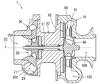
- the turbocharger 1 will be described with reference to FIG.
- the turbocharger 1 is attached to an internal combustion engine mounted on a vehicle, for example.
- the turbocharger 1 has three housings, an exhaust housing 10, an intake housing 20, and a bearing housing 30.
- the shaft 31 is supported by the bearing so as to be rotatable around the rotation axis ZC.
- a turbine 40 is provided in the exhaust housing 10.
- An impeller 50 (turbocharger impeller) is provided in the intake housing 20.
- the shaft 31 has a first end in the exhaust housing 10 and a second end in the intake housing 20.
- the turbine 40 is fixed to the first end.
- the impeller 50 is fixed to the second end.
- the turbine 40 and the impeller 50 are connected by a shaft 31.
- the turbine 40, the shaft 31, and the impeller 50 are integrally rotated around the rotation axis ZC.
- the exhaust housing 10 has an exhaust inlet (10A in FIG. 6), a scroll chamber 10S, and an exhaust outlet 10B. Exhaust gas from the internal combustion engine flows into the exhaust inlet.
- the scroll chamber 10 ⁇ / b> S guides the exhaust gas that has flowed into the turbine 40.
- the exhaust discharge port 10 ⁇ / b> B discharges exhaust gas after energy is recovered in the turbine 40.
- a variable valve 60 and VN plates 61 and 62 are provided in the exhaust housing 10.
- the variable valve 60 adjusts the flow rate of the exhaust gas flowing from the scroll chamber 10 ⁇ / b> S toward the turbine 40.
- VN plates 61 and 62 support variable valves. Illustration and description of the details of the drive mechanism that drives the variable valve 60 are omitted.
- the intake housing 20 has an intake inlet 20A, a scroll chamber 20C, and an intake discharge port (20B in FIG. 6). Intake air (air) sucked into the internal combustion engine flows from the intake air inlet 20A. The air transferred (pressed) by the impeller 50 passes through the scroll chamber 20C, which is a passage. The transferred air is discharged from the intake discharge port.
- a shroud member 21 and a scroll member 22 that form a scroll chamber 20 ⁇ / b> C are provided in the intake housing 20.
- the impeller 50 supercharges the internal combustion engine using the rotational power of the turbine 40.
- the accuracy of the shape of the impeller 50 greatly affects the intake efficiency.
- the impeller 50 includes a hub portion 51 and a plurality of blade portions 52 and 53.
- the hub portion 51 has a substantially truncated cone shape.
- the blade parts 52 and 53 are formed on the surface of the hub part 51 and transfer (pressure feed) the fluid flowing in from the direction of the rotation axis ZC to the outside in the radial direction.
- the accuracy of the shape of the blade portions 52 and 53 greatly affects the intake efficiency.
- the conventional impeller 50 was manufactured by precision casting. Precision casting requires a relatively long time. Therefore, a method for manufacturing an impeller in a short time has been conventionally desired. Instead of precision casting, a method of cutting (so-called cutting) the base material can be considered. However, this method leaves a groove on the surface of the impeller. Grooves can affect fluid flow and increase pressure loss. For this reason, the intake efficiency may be reduced by the groove. There is also a method of adding a surface treatment to eliminate the groove. However, this method is not preferable because the manufacturing time becomes long. Therefore, it is preferable that a groove portion that can further suppress the pressure loss when the base material is cut is left. Thereby, processing time can be shortened and pressure loss can be suppressed more.
- the impeller 50 will be described with reference to FIGS. As shown in FIGS. 2 to 4, the impeller 50 includes a hub portion 51 and a plurality of blade portions 52 and 53.
- the hub portion 51 has a substantially truncated cone shape whose diameter gradually increases along the rotation axis ZC direction.
- the blade parts 52 and 53 are formed on the surface of the hub part 51, and pump the fluid flowing in from the direction of the rotation axis ZC outward in the radial direction.
- a plurality of groove portions are formed on the surfaces of the hub portion 51 and the blade portions 52 and 53.
- a processing tool T for cutting the workpiece at the tip is used.
- the base material is cut by moving the processing tool T, and a groove is formed as a movement locus of the processing tool T.
- a plurality of point groups are milled using a tapered ball end mill as the processing tool T.
- a tapered ball end mill is used as the processing tool T.
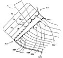
- the pressure loss is considered to be affected by the direction and heights H1 and H2 of the grooves 52A and 52B shown in FIG.
- the direction of the groove parts 52A and 52B is the longitudinal direction of the groove parts 52A and 52B.
- the heights H1 and H2 are the heights of the peaks 52T and 52Y formed at the edge of the groove.
- a plurality of groove portions are formed on the surfaces of the blade portions 52 and 53.
- the groove is formed in a direction that directs the fluid radially outward in order to suppress pressure loss. Thereby, when the impeller 50 rotates, the fluid can flow in from the direction of the rotation axis ZC and flow outward in the radial direction.
- the groove is formed so as to go from the intake inlet 20A to the scroll chamber 20C.
- the groove portion may have the shape of FIG. 3 or may not have the shape of FIG. For example, a part of the groove may be formed so as to go from the intake inlet 20A toward the shroud member 21. Thereby, a preferable effect can be exhibited.
- the groove portion is also formed on the surface of the hub portion 51. The groove is also formed so as to allow the fluid to flow radially outward.
- the cross section perpendicular to the longitudinal direction of the groove portions 52A and 52B is arcuate. However, depending on the machining state, the shape is not always circular. Adjacent grooves overlap at the edge along the longitudinal direction. Crests 52T and 52Y are formed along the longitudinal direction of the groove at the position where the edge overlaps. The peaks 52T and 52Y protrude from the surface of the blade.
- the dotted line in FIG. 4 shows a virtual surface 52Z in which the surfaces of the blade portions are flattened by shaving the mountain portions 52T and 52Y.
- the peak portions 52T and 52Y have heights H1 and H2 from the virtual surface 52Z or from the valley portions 52S and 52X.
- the height H2 of the high peak portion 52Y is, for example, 0.1 ⁇ m.
- the height H1 of the low peak portion 52T is, for example, 0.05 ⁇ m.
- the path pitches P1 and P2 of the groove portions 52A and 52B are made wider to reduce the number of groove portions. Thereby, the processing time by cutting can be further shortened.
- the path pitches P1 and P2 correspond to the intervals between the groove portions, and are substantially the same as the intervals D1 and D2 between the peaks shown in FIG.
- the path pitches P1 and P2 of the grooves are increased, the heights H1 and H2 of the peaks 52T and 52Y become higher. As a result, there is a concern about an increase in pressure loss due to the height of the peak.
- the blade portions 52 and 53 have a central region near the rotation axis ZC and an outer region far from the rotation axis ZC.
- the central region has a lower rotational speed than the outer region. Accordingly, it is considered that the pressure loss due to the height of the peak portion is smaller in the central region than in the outer region.
- the pass pitch P1 of the grooves in the outer region is set to be narrower than the pass pitch P2 of the grooves in the central region.
- the height H1 of the peak 52T in the outer region is set to be lower than the height H2 of the peak 52Y in the central region. Thereby, the pressure loss can be effectively suppressed.
- the impeller 50 can be manufactured in a few minutes. Thereby, an impeller can be manufactured in a shorter time than the case where it manufactures by precision casting.
- the groove is cut, and the pass pitch of the groove is changed at a specific position.
- the specific position (boundary position K) will be described with reference to FIG.
- the total number of passes Nt is the number of grooves in the blade 52 from the position closest to the rotation axis ZC to the position farthest from the rotation axis ZC.
- the total number of passes Nt corresponds to the number of passes of the machining tool.
- the hub-side pass number Nh is the number of grooves in the blade 52 from the position closest to the rotation axis ZC to the boundary position K.
- the shroud-side path number Ns is the number of groove portions from the position farthest from the rotation axis ZC to the boundary position K in the blade portion 52.
- the total length Lt is the length from the position closest to the rotation axis ZC in the blade portion 52 to the position farthest from the rotation axis ZC.
- the hub-side length Lh is a length from the position closest to the rotation axis ZC in the blade portion 52 to the boundary position K.
- the shroud side length Ls is a length from the position farthest from the rotation axis ZC in the blade portion 52 to the boundary position K.
- the hub-side path number Nh, the shroud-side path number Ns, and the hub-side length Lh are set so as to satisfy both of the following (Expression 1) and (Expression 2). Thereby, the position of the boundary position K is determined.
- the number of hub-side paths Nh, the number of shroud-side paths Ns, and the total number of paths Nt are integers because they are the number of grooves.
- the total number of paths Nt is set to an integer in an appropriate range according to the total length Lt.
- the impeller 50 is cut from the base material. Manufacture so that the number of grooves is smaller. Thereby, processing time can be shortened. Make the groove direction and height appropriate. Thereby, the pressure loss can be suppressed, and in particular, the pressure loss at the intake inlet 20A can be suppressed.
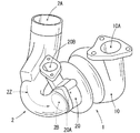
- the turbo unit has a turbocharger 1 and an inlet elbow 2 shown in FIG.
- the inlet elbow 2 is assembled to guide intake air (air) to the intake air inlet 20A of the turbocharger 1.
- the compressor has an intake housing 20 and an impeller.
- An intake discharge port 2 ⁇ / b> B of the inlet elbow 2 is connected to the intake port 20 ⁇ / b> A of the turbocharger 1.
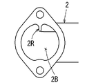
- the inlet elbow 2 has a substantially cylindrical shape having an intake inlet 2A and an intake discharge port 2B.
- the inlet elbow 2 has a curved shape in various directions in order to fit in a limited mounting space in the engine room of the vehicle. Therefore, the air that has passed through the inlet elbow 2 may turn in a predetermined direction.
- the air A1 passes through the inlet elbow 2 and turns in a predetermined direction.
- the air A1 turns counterclockwise when viewed from the A direction.
- the impeller 50 has the shape shown in FIGS. 2 and 3 and rotates in the clockwise direction. Therefore, as shown in FIG. 7, the turning direction of the air A1 and the rotating direction of the impeller 50 are different. In this case, the pressure loss is greater than when the air swirling direction and the impeller rotation direction are the same.
- the fluid turning restricting portion 2R protrudes radially inward from the inner wall of the inlet elbow 2.
- the fluid turning restricting portion 2R has a longitudinal length extending in the longitudinal direction (axial direction) of the inlet elbow 2. The longitudinal length corresponds to at least 2L shown in FIG.
- the fluid turning restricting portion 2R has a longitudinal length from at least the intake / discharge port 2B to the curved portion where the curvature of the curved shape of the inlet elbow 2 is equal to or greater than a predetermined curvature.
- the fluid turning restricting portion 2 ⁇ / b> R suppresses the inflowing air from turning along the inner wall of the inlet elbow 2. This suppresses pressure loss.
- the fluid swirl regulating unit 2R shown in FIG. 11 is a fluid swirl regulating unit shown in FIGS.
- the fluid swirl restricting portion 2R and the fluid swirl restricting members 2S and 2T in FIGS. 11 to 13 are provided in the vicinity of the intake and discharge ports of the inlet elbow.
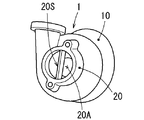
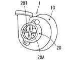
- the fluid swirl restricting portion 20R and the fluid swirl restricting members 20S and 20T in FIGS. 14 to 16 are provided near the intake air inlets 20aA and 20A of the intake housings 20a and 20.
- the fluid turning restricting member 2S has a plate shape along the longitudinal direction of the inlet elbow 2a.
- the fluid swirl regulating member 2S extends in the diameter direction and bridges between the inner walls of the inlet elbow 2a.
- the fluid turning restricting member 2S has a longitudinal length extending in the longitudinal direction of the inlet elbow 2a in the inlet elbow 2a.
- the fluid swirl regulating member 2S extends along an axis Z2 connecting the centers of the flow paths in the inlet elbow in FIG.
- the longitudinal length of the fluid swirl regulating member 2S is 2L as shown in FIG.
- the fluid swirl regulating member 2S has an edge that contacts the inner wall of the inlet elbow 2a.
- the edge is thicker than the other part of the fluid swirl regulating member 2S.
- the edge portion has an arc shape along the inner wall of the inlet elbow 2a, and is stably disposed in the inlet elbow 2a.
- the fluid turning restricting member 2T is a separate member from the inlet elbow 2a, and extends along the longitudinal direction (axial direction) of the inlet elbow 2a.
- the fluid turning restricting member 2T extends in the diameter direction and bridges between the inner walls of the inlet elbow 2a.
- the fluid turning restricting member 2T has a longitudinal length extending in the longitudinal direction of the inlet elbow 2a. The longitudinal length is 2L as shown in FIG.
- the fluid swirl regulating member 2T has an edge that contacts the inner wall of the inlet elbow 2a. The edge is thicker than the other part of the fluid swirl regulating member 2T.
- the edge portion has an arc shape along the inner wall of the inlet elbow 2a, and is stably disposed in the inlet elbow 2a.
- the inlet elbows 2 and 2a have fluid swirl restricting portions 2R and fluid swirl restricting members 2S and 2T.
- the fluid swirl restricting portion 20R has a rib shape protruding radially inward from the inner wall of the intake air inlet 20aA.
- the fluid turning restricting portion 20R has a longitudinal length extending in the direction of the rotation axis in the intake air inlet 20aA. The longitudinal length is set to an appropriate length from the input-side end of the intake air inlet 20aA to a position where it does not interfere with the impeller 50.
- the fluid swirl regulating member 20S has a plate shape along the rotation axis direction in the intake air inlet 20A.
- the fluid swirl regulating member 20S extends in the diameter direction and bridges between the inner walls of the intake air inlet 20A.
- the fluid swirl regulating member 20S has a longitudinal length extending in the direction of the rotation axis in the intake air inlet 20A. The longitudinal length is set to an appropriate length from the input side end of the intake air inlet 20A to a position where it does not interfere with the impeller 50.
- the fluid swirl regulating member 20S has an edge that contacts the inner wall of the intake air inlet 20A. The edge is thicker than the other part of the fluid swirl regulating member 20S.
- the edge portion has an arc shape along the inner wall of the intake air inlet 20A, and is stably disposed in the intake air inlet 20A.
- the fluid swirl regulating member 20T shown in FIG. 16 is a separate member from the intake housing and has a plate shape combined in a cross shape.
- the fluid swirl regulating member 20T extends in the diameter direction and bridges between the inner walls of the intake air inlet 20A.
- the fluid swirl regulating member 20T extends in the direction of the rotation axis in the intake air inlet 20A.
- the longitudinal length is set to an appropriate length from the input side end of the intake air inlet 20A to a position where it does not interfere with the impeller 50.
- the fluid swirl regulating member 20T has an edge that contacts the inner wall of the intake air inlet 20A.
- the edge is thicker than the other part of the fluid swirl regulating member 20T.
- the edge portion has an arc shape along the inner wall of the intake air inlet 20A, and is stably disposed in the intake air inlet 20A.
- the turbocharger has a fluid turning restricting portion 20R and fluid turning restricting members 20S and 20T. Thereby, the pressure loss of the fluid can be further suppressed.
- 11 to 13 rectify the outer peripheral portion of the sucked air in the vicinity of the intake discharge port of the inlet elbow. Thereby, the pressure loss of the fluid can be suppressed.
- 14 to 16 rectifies the outer peripheral portion of the sucked air near the intake air inlet of the intake housing. Thereby, the pressure loss of the fluid can be suppressed.
- Grooves are formed on the surfaces of the blade parts 52 and 53.
- the groove is set in an appropriate direction and an appropriate height. Thereby, a pressure loss can be suppressed suitably.
- the turbocharger impeller 50 is cut out from the base material.
- the blade portions 52 and 53 are formed by using the processing tool T so that the groove portion has an appropriate direction and an appropriate height. Thereby, the impeller 50 can be manufactured in a shorter time than manufacturing by precision casting.
- a fluid swirl regulating part can be further added to the turbocharger.
- the fluid swirl regulating unit is provided in the vicinity of the intake air inlet of the compressor (intake housing) or in the vicinity of the intake discharge port of the inlet elbow. Thereby, pressure loss can be further suppressed.
- the fluid swirl regulating members 2S and 2T may be separate members from the inlet elbow as shown in FIGS. 12 and 13, or may be integrated with the inlet elbow.
- the fluid swirl regulating member is a separate member from the inlet elbow, it can be fixed to the inlet elbow with a bolt or the like.
- the fluid swirl regulating members 20S and 20T may be separate members from the intake housing as shown in FIGS. 15 and 16, or may be integrated with the intake housing.
- the fluid swirl regulating member is a separate member from the intake housing, it can be fixed to the intake housing by a bolt or the like.
- the fluid swirl regulating portion 2R may be integrated with the inlet elbow as shown in FIG. 11, or may be a separate member from the inlet elbow. In the case where the fluid turning restricting portion 2R is a separate member from the inlet elbow, it can be fixed to the inlet elbow with a bolt or the like.
- the fluid rotation restricting portion 20R may be integrated with the intake housing as shown in FIG. 14 or may be a separate member. In the case of a separate member from the intake housing, the fluid turning restricting portion 20R can be fixed to the intake housing by a bolt or the like.
- the above embodiment is not limited to a vehicle equipped with an internal combustion engine, and can be applied to various applications.
- the pass pitches P1 and P2 of the grooves may be changed at the boundary position as described above. Instead of this, the path pitches P1 and P2 of the groove portions may be set gradually narrower as the distance from the rotation axis ZC increases from the side closer to the rotation axis ZC.
Abstract
Description
Ns≧Nh (式2) 1 ≦ Nh <Nt × (Lh / Lt) (Formula 1)
Ns ≧ Nh (Formula 2)
Claims (11)
- ターボチャージャ用インペラであって、
回転軸方向に沿って徐々に径が大きくなる略円錐台状のハブ部と、
前記ハブ部の表面に形成されて前記回転軸方向から流入してきた流体を径方向外側に圧送する複数の羽根部と、
前記羽根部の表面に形成され、前記インペラが回転時に前記回転軸方向から流入してきた流体を径方向外側へ流す方向に延出する複数本の溝部と、
前記羽根部の前記溝部の間に形成され前記溝部から突出しかつ前記溝部の長手方向に延出する山部を有し、前記回転軸から遠い外領域における前記山部が前記回転軸に近い中心領域における前記山部よりも低いターボチャージャ用インペラ。 An impeller for a turbocharger,
A substantially truncated cone-shaped hub portion whose diameter gradually increases along the rotation axis direction;
A plurality of blade portions that are formed on the surface of the hub portion and pump the fluid flowing in from the direction of the rotation axis radially outward;
A plurality of groove portions formed on the surface of the blade portion and extending in a direction in which the fluid that has flowed in from the direction of the rotation shaft when the impeller rotates rotates outward in the radial direction;
A central region formed between the groove portions of the blade portion and protruding from the groove portion and extending in the longitudinal direction of the groove portion, and the peak portion in the outer region far from the rotation axis is close to the rotation axis An impeller for a turbocharger that is lower than the peak portion in FIG. - 請求項1に記載のターボチャージャ用インペラであって、
前記外領域における前記溝部の間隔が前記中心領域における前記溝部の間隔よりも狭いターボチャージャ用インペラ。 The turbocharger impeller according to claim 1,
The turbocharger impeller, wherein an interval between the groove portions in the outer region is narrower than an interval between the groove portions in the central region. - 請求項1または2に記載のターボチャージャ用インペラの製造方法であって、
前記回転軸方向から流入した流体を径方向外側へ流す方向に加工工具を移動させて母材から前記羽根部を切削加工し、
前記羽根部を切削加工する際、前記加工工具によって前記羽根部に前記溝部を形成し、かつ隣り合う前記溝部の縁部が重なるように前記溝部を形成し、かつ前記外領域の前記山部が前記中心領域の前記山部よりも低くなるように前記溝部を形成するターボチャージャ用インペラの製造方法。 A method for producing an impeller for a turbocharger according to claim 1 or 2,
The blade is cut from the base material by moving a machining tool in a direction in which the fluid flowing in from the rotation axis direction flows radially outward,
When cutting the blade portion, the groove portion is formed in the blade portion by the processing tool, and the groove portion is formed so that edges of the adjacent groove portions overlap, and the crest portion in the outer region is formed. A method for manufacturing an impeller for a turbocharger, wherein the groove portion is formed to be lower than the peak portion of the central region. - ターボチャージャであって、
コンプレッサを有し、前記コンプレッサが、
請求項1または2に記載のインペラを収容するハウジングと、
前記コンプレッサにおける流体の流入口の近傍に形成されて、流体が前記コンプレッサの内壁に沿って旋回することを規制する流体旋回規制部を有するターボチャージャ。 A turbocharger,
A compressor, wherein the compressor
A housing that houses the impeller according to claim 1 or 2,
A turbocharger having a fluid swirl restricting portion that is formed in the vicinity of the fluid inlet of the compressor and restricts the swirling of the fluid along the inner wall of the compressor. - 請求項4に記載のターボチャージャであって、
前記流体旋回規制部は、前記コンプレッサの前記内壁から径方向内側に向かって突出し、前記回転軸に沿って延びるリブ状であるターボチャージャ。 The turbocharger according to claim 4, wherein
The fluid swirl regulating part is a turbocharger that protrudes radially inward from the inner wall of the compressor and extends along the rotation axis. - 請求項4に記載のターボチャージャであって、
前記流体旋回規制部は、直径方向に延出し前記コンプレッサの前記内壁を架橋し、前記回転軸に沿って延びる板状であるターボチャージャ。 The turbocharger according to claim 4, wherein
The fluid swirl regulating part is a turbocharger that extends in the diameter direction, bridges the inner wall of the compressor, and has a plate shape extending along the rotation axis. - 請求項4~6のいずれか1つに記載のターボチャージャであって、
前記流体旋回規制部は、前記コンプレッサの前記内壁と別体であって、前記内壁に取り付けられるターボチャージャ。 A turbocharger according to any one of claims 4 to 6,
The fluid swirl regulating unit is a turbocharger that is separate from the inner wall of the compressor and is attached to the inner wall. - ターボユニットであって、
請求項1または2に記載のインペラを収容するハウジングを備えるコンプレッサと、
前記コンプレッサに接続されて前記インペラの前記回転軸方向から流体を流入させる配管であるインレットエルボと、
前記インレットエルボにおける流体の吐出口の近傍に形成され、流体が前記インレットエルボの内壁に沿って旋回することを規制する流体旋回規制部を有するターボユニット。 A turbo unit,
A compressor comprising a housing for accommodating the impeller according to claim 1 or 2,
An inlet elbow that is a pipe connected to the compressor and for allowing fluid to flow in from the direction of the rotation axis of the impeller;
A turbo unit having a fluid turning restricting portion that is formed in the vicinity of a fluid discharge port in the inlet elbow and restricts the fluid from turning along the inner wall of the inlet elbow. - 請求項8に記載のターボユニットであって、
前記流体旋回規制部は、前記インレットエルボの前記内壁から径方向内側に向かって突出し、前記インレットエルボの長手方向に延びるリブ状であるターボユニット。 The turbo unit according to claim 8,
The fluid swirl restricting portion is a turbo unit that protrudes radially inward from the inner wall of the inlet elbow and extends in the longitudinal direction of the inlet elbow. - 請求項8に記載のターボユニットであって、
前記流体旋回規制部は、直径方向に延出し、前記インレットエルボの前記内壁を架橋し、前記インレットエルボの長手方向に延びる板状であるターボユニット。 The turbo unit according to claim 8,
The fluid swirl regulating part is a turbo unit that extends in the diameter direction, bridges the inner wall of the inlet elbow, and has a plate shape extending in the longitudinal direction of the inlet elbow. - 請求項8~10のいずれか1つに記載のターボユニットであって、
前記流体旋回規制部は、前記インレットエルボの前記内壁と別体であって、前記内壁に取り付けられるターボユニット。 A turbo unit according to any one of claims 8 to 10,
The fluid swirl regulating unit is a turbo unit that is separate from the inner wall of the inlet elbow and is attached to the inner wall.
Priority Applications (5)
| Application Number | Priority Date | Filing Date | Title |
|---|---|---|---|
| US14/761,969 US10323518B2 (en) | 2013-01-23 | 2014-01-22 | Turbocharger impeller, method of manufacturing the same, turbocharger, and turbocharger unit |
| AU2014208575A AU2014208575B2 (en) | 2013-01-23 | 2014-01-22 | Turbocharger impeller, method of manufacturing the same, turbocharger, and turbocharger unit |
| BR112015017452A BR112015017452A2 (en) | 2013-01-23 | 2014-01-22 | turbocharger rotor, method of manufacture, turbocharger and turbocharger unit |
| EP14743296.7A EP2949945B1 (en) | 2013-01-23 | 2014-01-22 | Impeller for turbocharger, method for manufacturing same, turbocharger, and turbo unit |
| CA2898422A CA2898422C (en) | 2013-01-23 | 2014-01-22 | Turbocharger impeller, method of manufacturing the same, turbocharger, and turbocharger unit |
Applications Claiming Priority (2)
| Application Number | Priority Date | Filing Date | Title |
|---|---|---|---|
| JP2013009996A JP5611379B2 (en) | 2013-01-23 | 2013-01-23 | Impeller for turbocharger, method for manufacturing impeller for turbocharger, turbocharger, and turbo unit |
| JP2013-009996 | 2013-01-23 |
Publications (1)
| Publication Number | Publication Date |
|---|---|
| WO2014115761A1 true WO2014115761A1 (en) | 2014-07-31 |
Family
ID=51227552
Family Applications (1)
| Application Number | Title | Priority Date | Filing Date |
|---|---|---|---|
| PCT/JP2014/051243 WO2014115761A1 (en) | 2013-01-23 | 2014-01-22 | Impeller for turbocharger, method for manufacturing same, turbocharger, and turbo unit |
Country Status (7)
| Country | Link |
|---|---|
| US (1) | US10323518B2 (en) |
| EP (1) | EP2949945B1 (en) |
| JP (1) | JP5611379B2 (en) |
| AU (1) | AU2014208575B2 (en) |
| BR (1) | BR112015017452A2 (en) |
| CA (1) | CA2898422C (en) |
| WO (1) | WO2014115761A1 (en) |
Families Citing this family (21)
| Publication number | Priority date | Publication date | Assignee | Title |
|---|---|---|---|---|
| DE102013011458A1 (en) * | 2013-07-10 | 2015-01-15 | Mann+Hummel Gmbh | Compressor housing of a centrifugal compressor |
| JP1523931S (en) * | 2014-12-19 | 2015-05-18 | ||
| USD762840S1 (en) * | 2015-03-17 | 2016-08-02 | Wilkins Ip, Llc | Impeller |
| JP6011666B2 (en) * | 2015-03-19 | 2016-10-19 | 株式会社豊田自動織機 | Rotating body |
| CN105458372B (en) * | 2015-12-29 | 2018-03-09 | 北京理工大学 | A kind of side milling error tool path scheduling method based on non-extended straight-line surface |
| DE102016209256A1 (en) * | 2016-05-27 | 2017-11-30 | Robert Bosch Gmbh | Device for compressing or expanding a fluid and method for producing a device for compressing or expanding a fluid |
| JP6806551B2 (en) * | 2016-12-14 | 2021-01-06 | 株式会社豊田中央研究所 | Centrifugal compressor, turbocharger |
| USD847861S1 (en) * | 2017-03-21 | 2019-05-07 | Wilkins Ip, Llc | Impeller |
| USD986287S1 (en) | 2017-04-05 | 2023-05-16 | Wayne/Scott Fetzer Company | Pump component |
| USD868117S1 (en) * | 2017-04-05 | 2019-11-26 | Wayne/Scott Fetzer Company | Pump component |
| CN107869359A (en) * | 2017-12-01 | 2018-04-03 | 无锡宇能选煤机械厂 | Streamlined thick vane turbochargers armature spindle |
| JP6992504B2 (en) * | 2017-12-27 | 2022-01-13 | トヨタ自動車株式会社 | Impeller manufacturing method |
| CN109973423B (en) * | 2017-12-28 | 2021-05-18 | 宁波方太厨具有限公司 | Water pump impeller for cleaning machine and application thereof |
| CN111771172B (en) * | 2018-02-28 | 2021-09-28 | 大金工业株式会社 | Method for manufacturing machined product, tool path calculation method, machined product, and impeller |
| CN108952949B (en) * | 2018-07-05 | 2020-12-22 | 常州平江电气设备有限公司 | Turbocharger with good gas fluidity |
| JP7124652B2 (en) * | 2018-11-13 | 2022-08-24 | 株式会社豊田自動織機 | Manufacturing method of TiAl alloy impeller |
| CN110259721A (en) * | 2019-06-13 | 2019-09-20 | 西北工业大学 | A kind of centrifugal-flow compressor impeller with high pressure ratio |
| USD960935S1 (en) * | 2020-06-08 | 2022-08-16 | Electromechanical Research Laboratories, Inc. | Impeller |
| JP7310739B2 (en) | 2020-07-14 | 2023-07-19 | 株式会社豊田自動織機 | Impeller and its manufacturing method |
| JP2022056948A (en) * | 2020-09-30 | 2022-04-11 | 株式会社豊田自動織機 | Centrifugal compressor |
| KR200495900Y1 (en) * | 2021-09-16 | 2022-09-16 | 백동진 | Power increase of internal combustion engines Smoke reduction reducer |
Citations (5)
| Publication number | Priority date | Publication date | Assignee | Title |
|---|---|---|---|---|
| JPS57202800U (en) * | 1981-06-18 | 1982-12-23 | ||
| JPH09100797A (en) | 1995-10-06 | 1997-04-15 | Kobe Steel Ltd | Impeller of centrifugal compressor |
| JP2002036020A (en) * | 2000-07-31 | 2002-02-05 | Ishikawajima Harima Heavy Ind Co Ltd | Machining method of large impeller |
| JP2003120574A (en) | 2001-10-17 | 2003-04-23 | Asmo Co Ltd | Motor pump |
| JP2005163640A (en) | 2003-12-03 | 2005-06-23 | Mitsubishi Heavy Ind Ltd | Impeller for compressor |
Family Cites Families (16)
| Publication number | Priority date | Publication date | Assignee | Title |
|---|---|---|---|---|
| US1531967A (en) * | 1923-07-26 | 1925-03-31 | Gen Electric | Propeller |
| US1864803A (en) * | 1929-07-11 | 1932-06-28 | John M Clark | Marine and aeroplane propeller |
| DE833100C (en) * | 1950-08-23 | 1952-03-03 | Inconex Handelsgesellschaft M | Turbo compressor blade with boundary layer fences |
| US3033293A (en) * | 1958-10-20 | 1962-05-08 | Otto L Bihlmire | Boat propeller |
| US3481531A (en) * | 1968-03-07 | 1969-12-02 | United Aircraft Canada | Impeller boundary layer control device |
| US4720239A (en) * | 1982-10-22 | 1988-01-19 | Owczarek Jerzy A | Stator blades of turbomachines |
| GB2188101B (en) * | 1986-03-22 | 1990-12-05 | Usui Kokusai Sangyo Kk | Fan blades |
| KR900007252B1 (en) * | 1986-05-19 | 1990-10-06 | 우수이 고꾸사이 산교 가부시기가이샤 | Blades for low speed propeller fan |
| US4930729A (en) * | 1986-05-22 | 1990-06-05 | Rolls-Royce Plc | Control of fluid flow |
| JPH0166500U (en) | 1987-10-26 | 1989-04-27 | ||
| DE4319628A1 (en) | 1993-06-15 | 1994-12-22 | Klein Schanzlin & Becker Ag | Structured surfaces of fluid machine components |
| US6280144B1 (en) * | 1998-11-10 | 2001-08-28 | Charles S. Powers | Propellers and impellers with stress-relieving recesses |
| WO2005054681A1 (en) | 2003-12-03 | 2005-06-16 | Mitsubishi Heavy Industries, Ltd. | Impeller for compressor |
| JP5515222B2 (en) | 2007-02-13 | 2014-06-11 | ダイキン工業株式会社 | Blower impeller |
| JP4400686B2 (en) * | 2008-01-07 | 2010-01-20 | ダイキン工業株式会社 | Propeller fan |
| DE102008024115A1 (en) | 2008-05-17 | 2009-11-19 | Bosch Mahle Turbo Systems Gmbh & Co. Kg | Exhaust gas turbocharger for use with combustion engine for vehicle, has compressor wheel arranged on intake side and connected with vehicle in torque proof manner |
-
2013
- 2013-01-23 JP JP2013009996A patent/JP5611379B2/en active Active
-
2014
- 2014-01-22 EP EP14743296.7A patent/EP2949945B1/en active Active
- 2014-01-22 US US14/761,969 patent/US10323518B2/en active Active
- 2014-01-22 WO PCT/JP2014/051243 patent/WO2014115761A1/en active Application Filing
- 2014-01-22 BR BR112015017452A patent/BR112015017452A2/en not_active Application Discontinuation
- 2014-01-22 CA CA2898422A patent/CA2898422C/en not_active Expired - Fee Related
- 2014-01-22 AU AU2014208575A patent/AU2014208575B2/en not_active Ceased
Patent Citations (5)
| Publication number | Priority date | Publication date | Assignee | Title |
|---|---|---|---|---|
| JPS57202800U (en) * | 1981-06-18 | 1982-12-23 | ||
| JPH09100797A (en) | 1995-10-06 | 1997-04-15 | Kobe Steel Ltd | Impeller of centrifugal compressor |
| JP2002036020A (en) * | 2000-07-31 | 2002-02-05 | Ishikawajima Harima Heavy Ind Co Ltd | Machining method of large impeller |
| JP2003120574A (en) | 2001-10-17 | 2003-04-23 | Asmo Co Ltd | Motor pump |
| JP2005163640A (en) | 2003-12-03 | 2005-06-23 | Mitsubishi Heavy Ind Ltd | Impeller for compressor |
Also Published As
| Publication number | Publication date |
|---|---|
| BR112015017452A2 (en) | 2017-07-11 |
| EP2949945B1 (en) | 2019-08-07 |
| CA2898422A1 (en) | 2014-07-31 |
| AU2014208575B2 (en) | 2016-03-17 |
| JP5611379B2 (en) | 2014-10-22 |
| JP2014141909A (en) | 2014-08-07 |
| US10323518B2 (en) | 2019-06-18 |
| CA2898422C (en) | 2017-04-04 |
| EP2949945A4 (en) | 2016-10-05 |
| AU2014208575A1 (en) | 2015-09-10 |
| EP2949945A1 (en) | 2015-12-02 |
| US20150354359A1 (en) | 2015-12-10 |
Similar Documents
| Publication | Publication Date | Title |
|---|---|---|
| WO2014115761A1 (en) | Impeller for turbocharger, method for manufacturing same, turbocharger, and turbo unit | |
| CN104421199B (en) | The asymmetrical bilateral turbo-charger impeller of function and diffuser | |
| US8702381B2 (en) | Simplified variable geometry turbocharger with vane rings | |
| JP5665486B2 (en) | Turbine housing of twin scroll turbocharger | |
| US8226358B2 (en) | Turbine and turbocharger having the same | |
| EP2863032B1 (en) | Centrifugal compressor | |
| EP2994647B1 (en) | Centrifugal compressor with inlet duct having swirl generators | |
| CN105782073B (en) | Multistage radial compressor baffle | |
| JPWO2010047259A1 (en) | Scroll structure of radial turbine | |
| KR20120014217A (en) | Turbine rotor | |
| WO2016031017A1 (en) | Expansion turbine and turbocharger | |
| CN106460646B (en) | Turbine shell, turbine, core for casting turbine shell, and method for manufacturing turbine shell | |
| JP5398515B2 (en) | Radial turbine blades | |
| JP6801009B2 (en) | Turbine wheels, turbines and turbochargers | |
| JP2010001874A (en) | Turbine impeller, radial turbine, and supercharger | |
| WO2022054561A1 (en) | Turbine wheel, turbine, and turbocharger | |
| WO2015002228A1 (en) | Scroll part structure and supercharger | |
| JP7008789B2 (en) | Radius inflow turbine and turbocharger | |
| JP7130675B2 (en) | Turbine rotor blade, turbocharger, and turbine rotor blade manufacturing method | |
| JP2007192180A (en) | Turbine for turbocharger | |
| WO2018155532A1 (en) | Supercharger | |
| JP7413514B2 (en) | Scroll casing and centrifugal compressor | |
| WO2021140569A1 (en) | Turbine and turbocharger | |
| WO2018131213A1 (en) | Radial-inflow-type turbine, turbocharger, and method for assembling turbocharger | |
| Bang et al. | DESIGNING EXPERIENCE OF AUTOMOTIVE TURBOCHARGER IMPELLER FOR FLANK MILLING |
Legal Events
| Date | Code | Title | Description |
|---|---|---|---|
| 121 | Ep: the epo has been informed by wipo that ep was designated in this application |
Ref document number: 14743296 Country of ref document: EP Kind code of ref document: A1 |
|
| ENP | Entry into the national phase |
Ref document number: 2898422 Country of ref document: CA |
|
| WWE | Wipo information: entry into national phase |
Ref document number: 14761969 Country of ref document: US |
|
| NENP | Non-entry into the national phase |
Ref country code: DE |
|
| REG | Reference to national code |
Ref country code: BR Ref legal event code: B01A Ref document number: 112015017452 Country of ref document: BR |
|
| WWE | Wipo information: entry into national phase |
Ref document number: 2014743296 Country of ref document: EP |
|
| ENP | Entry into the national phase |
Ref document number: 2014208575 Country of ref document: AU Date of ref document: 20140122 Kind code of ref document: A |
|
| ENP | Entry into the national phase |
Ref document number: 112015017452 Country of ref document: BR Kind code of ref document: A2 Effective date: 20150722 |