WO2014115302A1 - 表示装置、マルチ表示システム、および設置位置検出方法 - Google Patents
表示装置、マルチ表示システム、および設置位置検出方法 Download PDFInfo
- Publication number
- WO2014115302A1 WO2014115302A1 PCT/JP2013/051593 JP2013051593W WO2014115302A1 WO 2014115302 A1 WO2014115302 A1 WO 2014115302A1 JP 2013051593 W JP2013051593 W JP 2013051593W WO 2014115302 A1 WO2014115302 A1 WO 2014115302A1
- Authority
- WO
- WIPO (PCT)
- Prior art keywords
- identification information
- display
- device identification
- display device
- unit
- Prior art date
- Legal status (The legal status is an assumption and is not a legal conclusion. Google has not performed a legal analysis and makes no representation as to the accuracy of the status listed.)
- Ceased
Links
Images






Classifications
-
- G—PHYSICS
- G06—COMPUTING OR CALCULATING; COUNTING
- G06F—ELECTRIC DIGITAL DATA PROCESSING
- G06F3/00—Input arrangements for transferring data to be processed into a form capable of being handled by the computer; Output arrangements for transferring data from processing unit to output unit, e.g. interface arrangements
- G06F3/14—Digital output to display device ; Cooperation and interconnection of the display device with other functional units
- G06F3/1423—Digital output to display device ; Cooperation and interconnection of the display device with other functional units controlling a plurality of local displays, e.g. CRT and flat panel display
- G06F3/1446—Digital output to display device ; Cooperation and interconnection of the display device with other functional units controlling a plurality of local displays, e.g. CRT and flat panel display display composed of modules, e.g. video walls
-
- G—PHYSICS
- G09—EDUCATION; CRYPTOGRAPHY; DISPLAY; ADVERTISING; SEALS
- G09G—ARRANGEMENTS OR CIRCUITS FOR CONTROL OF INDICATING DEVICES USING STATIC MEANS TO PRESENT VARIABLE INFORMATION
- G09G2300/00—Aspects of the constitution of display devices
- G09G2300/02—Composition of display devices
- G09G2300/026—Video wall, i.e. juxtaposition of a plurality of screens to create a display screen of bigger dimensions
-
- G—PHYSICS
- G09—EDUCATION; CRYPTOGRAPHY; DISPLAY; ADVERTISING; SEALS
- G09G—ARRANGEMENTS OR CIRCUITS FOR CONTROL OF INDICATING DEVICES USING STATIC MEANS TO PRESENT VARIABLE INFORMATION
- G09G2356/00—Detection of the display position w.r.t. other display screens
-
- G—PHYSICS
- G09—EDUCATION; CRYPTOGRAPHY; DISPLAY; ADVERTISING; SEALS
- G09G—ARRANGEMENTS OR CIRCUITS FOR CONTROL OF INDICATING DEVICES USING STATIC MEANS TO PRESENT VARIABLE INFORMATION
- G09G2370/00—Aspects of data communication
- G09G2370/12—Use of DVI or HDMI protocol in interfaces along the display data pipeline
Definitions
- the present invention relates to a display device, a multi-display system, and an installation position detection method.
- Patent Document 1 discloses a multi-display system using a display device having four interfaces capable of bidirectional data transfer in the vertical and horizontal directions.
- one display device is set as the master.
- the master display device communicates its own address to the display devices adjacent to the top, bottom, left, and right, and each display device automatically sets its own address according to the received data and the direction in which the data is received.
- the set self address is communicated.
- Patent Document 2 includes a semi-cylindrical plate on the top, bottom, left, and right side surfaces, and each display device is installed so that the planes of the corresponding plates of the display devices adjacent to the top, bottom, left, and right contact each other. Is disclosed.
- the upper and lower plates and the left and right plates are configured to interlock with each other while maintaining a difference in angle.
- Each display device can automatically acquire its own address by detecting the rotation angle of its upper, lower, left and right plates.
- Patent Document 1 it is necessary to connect communication cables vertically and horizontally to each display device, and it is necessary to control four bidirectional communication interfaces per unit, which is complicated. Processing is complicated. Further, in the technique disclosed in Patent Document 1, the user needs to set one display device as a master, and the display device set as the master needs to instruct other display devices to start address automatic setting. Cost. Further, when a failure occurs in any one of the display devices and the one is replaced, it is necessary to re-execute the process for instructing the start of automatic address setting. Further, in the case of a display device in which one failed device is set as a master, one display device is set as the master again, and the display device set as the master starts automatic address setting for another display device. Need to be instructed.
- Patent Document 2 the process of setting one display device as a master and the process of instructing another display device to start address automatic setting by the display device set as the master are unnecessary. Become.
- the one disclosed in Patent Document 2 requires a complicated mechanical mechanism called a plate that interlocks while maintaining an angular difference in the vertical and horizontal directions.
- the plate interlocking mechanism must be made highly accurate, and the number of display devices constituting the multi-display system is increased. Restrictions arise.
- ID identification information
- a configuration of a multi-display system having no display device in the center for example, 3 In the case of a system in which there is no central one in the case of three units ⁇
- the ID cannot be set correctly.
- the present invention eliminates complicated processing, and can automatically set display position information of each display device without depending on the configuration of the system, a display device, a multi-display system, and An installation position detection method is provided.
- a display device includes, in a display device used in a multi-display system, an identification information storage unit that stores own device identification information, and upper and lower portions of the display device.
- the four communication units provided at the left and right ends, the communication interface, and the device identification information read from the identification information storage unit are output via the four communication units, and are arranged adjacent to each other.
- the other device identification information which is the identification information of the other display device, is captured from the other display device via the communication unit, and the own device identification information and the other device identification information are output via the communication interface.
- a control unit is, in a display device used in a multi-display system, an identification information storage unit that stores own device identification information, and upper and lower portions of the display device.
- a multi-display system is a multi-display system including a plurality of display devices, and each of the plurality of display devices stores its own device identification information.
- Identification information storage unit four communication units provided at the top, bottom, left, and right ends of the display device, a communication interface, and the device identification information read from the identification information storage unit.
- the other apparatus identification information which is the identification information of the said other display apparatus is taken in via the said communication part from the other display apparatus arrange
- an installation position detection method is an installation position detection method for a plurality of display devices in a multi-display system.
- the number of display devices and display position information can be set without manually specifying the number of display devices and the display position of each display device. Further, according to the present invention, complicated processing is not necessary, and display position information of each display device can be set without depending on the configuration of the multi-display system.
- FIG. 1 is a block diagram showing a basic configuration of a display device according to the present invention.
- a display device 101-1 according to the present invention is a display device used in a multi-display system, and includes an identification information storage unit 116, communication units 120a to 120d, a communication interface 118, and a control unit 114.
- an identification information storage unit 116 for storing information and instructions.
- the identification information storage unit 116 stores its own device identification information.
- the communication units 120a to 120d are provided at the top, bottom, left and right ends of the display device 101-1. More specifically, the communication units 120a to 120d are provided on the top surface, the bottom surface, the left side surface, and the right side surface of the display device 101-1, as viewed from the front.
- the communication interface 118 is an interface for communicating with an external device.
- the control unit 114 outputs the own device identification information read from the identification information storage unit 116 via the four communication units 120a to 120d, and communicates with the other adjacent display devices 101-2 to 101-5.
- the other device identification information that is the identification information of the other display device is taken in via the units 120a to 120d, and the own device identification information and the other device identification information are output via the communication interface 118.
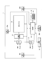
- FIG. 2 is a block diagram showing a configuration of the display device 1 according to the first embodiment of the present invention.
- the display device 1 includes an input interface 11, an output interface 17, a video processing unit 12, a display panel 13, a control unit 14, a memory 15, an identification information storage area 16, an output interface 17, and a communication interface 18.
- NFC Near Field Communication
- the input interface 11 has a plurality of types of input terminals such as an HDMI (High Definition Multimedia Interface) input terminal and a D-sub input terminal.
- the video signal from the input interface 11 is switched based on the control of the control unit 14 and supplied to the video processing unit 12.
- the output interface 17 has the same type of terminal as the input interface 11 and outputs a video signal.
- the output interface 17 may output the video signal input to the input interface 81 from the same type of output terminal as it is, or change the video format of the selected input video signal and output it from an arbitrary output terminal. Also good.
- the video processing unit 12 performs processing such as video correction processing and color correction processing.
- the output of the video processing unit 12 is supplied to the display panel 13.
- the display panel 13 is an LCD (Liquid Crystal Display) panel, for example, and displays an image based on the video signal from the video processing unit 12.
- the control unit 14 includes a CPU (Central Processing Unit) and controls the entire device.
- a memory 15 is provided for the control unit 14.
- the memory 15 includes an identification information storage area 16. In the identification information storage area 16, device identification information unique to the device is stored.
- a communication interface 18 is provided for the control unit 14.
- an RS-232C, USB (Universal Serial Bus) terminal, or LAN (Local Area Network) terminal is used as the communication interface 18.
- RS-232C and USB have an input terminal and an output terminal.
- the LAN terminal may include a plurality of systems.
- the display device 10 is provided with four NFC communication units 20a to 20d. As shown in FIG. 3, these NFC communication units 20a to 20d are arranged at substantially the center (including the center) of the four sides (the top surface, the bottom surface, the left side surface, and the right side surface) of the bezel 21 around the display device 1.
- NFC is an international standard for short-range wireless communication for non-contact data communication between devices. According to NFC, for example, communication can be performed within a distance of about 10 cm.
- the NFC communication units 20a to 20d use the NFC communication units 20a to 20d to connect each device read from the identification information storage area 16 between adjacent display devices. Device identification information is transmitted and received.
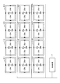
- FIG. 4 is a diagram showing a multi-display system according to the first embodiment of the present invention.
- a multi-display system is constructed by a total of 12 display devices 1-1 to 1-12, 4 in the horizontal direction and 3 in the vertical direction.
- the display devices 1-1 to 1-12 are each provided with an identification information storage area 16 as shown in FIG.
- the identification information storage area 16 of each of the display devices 1-1 to 1-12 device identification information unique to the device is stored.
- the display devices 1-1 to 1-12 include “I”, “K”, “B”, “G”, “E”, “A” as device identification information. , “F”, “J”, “D”, “H”, “L”, and “C”, respectively. These pieces of device identification information are stored in the identification information storage areas 16 of the display devices 1-1 to 1-12, respectively.
- the display devices 1-1 to 1-12 are connected to the control device 2 through the communication interface 18, respectively.
- the control device 2 and a network hub (not shown) are connected by a LAN cable, and the network hub and the display devices 1-1 to 1-12 are connected by a LAN cable.
- Control device 2 outputs a video signal to be displayed in the entire multi-display system.
- the control device 2 may distribute video signals to be displayed by the display devices 1-1 to 1-12 individually and in parallel to the display devices 1-1 to 1-12.
- the control device 2 distributes video signals to be displayed in the entire multi-display system to any one unit (generally, a display device installed at the end of the multi-display system).
- the same video signal may be output to another connected display device (daisy chain connection).
- each of the display devices 1-1 to 1-12 receives information about its own arrangement position in the multi-display system from the control device 2, and the video to be displayed by the display device Cut out the signal area and display it. Information regarding the arrangement position in the multi-display system will be described later.
- the NFC communication units 20a to 20d are provided on the four sides of the bezel around each of the display devices 1-1 to 1-12.
- the NFC communication units 20a to 20d can transmit and receive device identification information between adjacent display devices in the display devices 1-1 to 1-12. It should be noted that the NFC communicable distance is within about 10 cm, and if each surface of the display devices 1-1 to 1-12 is sufficiently wide, it is impossible to communicate with other than the adjacent NFC communication unit.
- the control unit 14 of each of the display devices 1-1 to 1-12 detects the presence or absence of an adjacent display device using the NFC communication units 20a to 20d, and if there is an adjacent display device, identification information of the display device To get. When there is no adjacent display device, special identification information (for example, “0 (zero)”) is acquired. Then, in response to an output request from the control device 2, the control unit 14 collectively identifies the device identification information of the own device and other device identification information of other adjacent display devices by the communication interface 18. Output as information.
- the other device identification information includes left other device identification information, right other device identification information, upper other device identification information, and lower other device identification information.
- the left other device identification information is device identification information that the left display device has in the front view of the device itself.
- the right other apparatus identification information is apparatus identification information that the right display apparatus has in the front view of the apparatus itself.
- the upper other device identification information is device identification information that the upper display device has in the front view of the device itself.
- the lower other device identification information is device identification information that the lower display device has in the front view of its own device. That is, the identification information of the other device is handled in association with the direction in which the other device is adjacent.
- the position acquisition unit included in the control device 2 requests the display devices 1-1 to 1-12 to output device identification information, and based on the device identification information output by the display devices 1-1 to 1-12, The position of each of the plurality of display devices in the multi-display system is acquired.
- the control unit 14 of each of the display devices 1-1 to 1-12 may use an array or structure having five elements when outputting the device identification information.
- the order of the elements is determined in advance as, for example, “own device identification number”, “left other device identification number”, “right other device identification number”, “upper other device identification number”, and “lower other device identification number”. Keep it. By doing in this way, handling of apparatus identification information in a position acquisition part becomes easy.
- 5 and 6 show the arrangement of the display devices 1-1 to 1-12 based on the device identification information sent from the display devices 1-1 to 1-12 in the position acquisition unit of the control device 2 in the multi-display system. It is a flowchart which shows the process which determines a position.
- the control device 2 can communicate with each of the display devices 1-1 to 1-12, but does not grasp the position of each display device in the multi-display system. Therefore, the position acquisition unit included in the control device 2 requests the display devices 1-1 to 1-12 to output device identification information (step S1).
- the display devices 1-1 to 1-12 that have received the output request for the device identification information output by the control device 2 are the own device identification information, the left other device identification information, the right other device identification information, Information including upper other apparatus identification information and lower other apparatus identification information is output.
- the position acquisition unit receives these pieces of information (step S2). Then, the position acquisition unit receives device identification information (local device identification information, left other device identification information, right other device identification information, upper other device identification information, lower other device identification) from the display devices 1-1 to 1-12. It is determined whether or not (information) has been acquired (step S3).
- device identification information local device identification information, left other device identification information, right other device identification information, upper other device identification information, lower other device identification
- the display devices 1-1 to 1-12 when a multi-display system is constructed with a total of 12 display devices 1-1 to 1-12, 4 in the horizontal direction and 3 in the vertical direction, the display devices 1-1 to 1-
- the device identification information is acquired from 12
- the information as shown in FIG. 7 is obtained from the display devices 1-1 to 1-12.
- “-” in FIG. 7 indicates that there is no adjacent other device.
- the display device 1-1 it indicates that there are no other devices on the left and upper sides, and the device identification information is (I, 0, K, 0, E).
- step S3 when device identification information is acquired from the display devices 1-1 to 1-12, the position acquisition unit forms a device identification information unit from these pieces of information (step S4). And a position acquisition part couple
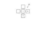
- a device identification information unit U1 as shown in FIG. 8 is formed from the device identification information obtained from the display device 1-1. A blank in the device identification information unit indicates that no other device exists.
- “K” is acquired as its own device identification information
- “I” is acquired as the left side other device identification information
- “B” is acquired as the right side other device identification information
- “A” is acquired as the side other apparatus identification information.
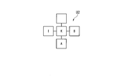
- a device identification information unit U2 as shown in FIG. 9 is formed from the device identification information obtained from the display device 1-2.
- FIG. 6 shows the apparatus identification information unit combining process in step S5.
- the position acquisition unit first acquires an arbitrary device identification information unit from the device identification information units formed by the display devices 1-1 to 1-12 (step S101). Next, the position acquisition unit acquires any other device identification information unit from the device identification information units formed by the display devices 1-1 to 1-12, respectively (step S102). Then, the position acquisition unit compares the two acquired device identification information units (step S103), and determines whether there is a portion having the same device identification information (step S104). If there is a portion that becomes the same device identification information (step S104: Yes), the position acquisition unit makes the device identification information common to the two device identification information units so that the portions that become the same device identification information overlap. Are combined to generate a coupling device identification information unit (step S105).
- the device identification information unit U1 from the display device 1-1 is acquired in step S101, and the device identification information unit U2 from the display device 1-2 is acquired in step S102.
- the position acquisition unit sets the device identification information unit so that the portions of the device identification information “I” and the device identification information “K” overlap as shown in FIG.
- the combined device identification information unit UA is generated (step S105).
- step S104 if there is no portion that becomes the same device identification information (step S104: No), the connection is suspended (step S106), and the process returns to step S102.
- step S105 when the device identification information unit is generated by combining the device identification information units, the position acquisition unit determines whether all the device identification information units are combined (step S107). If all the device identification information units are not combined (step S107: No), the position acquisition unit selects any other device identification information from the device identification information units formed from the display devices 1-1 to 1-12. A unit is acquired (step S108). Then, the position acquisition unit compares the acquired device identification information unit with the coupling device identification information unit (step S109), and determines whether there is a portion having the same device identification information (step S110). .
- step S110 If there is a portion that becomes the same device identification information (step S110: Yes), the position acquisition unit combines the device identification information unit and the coupling device identification information unit so that the portions that become the same device identification information overlap. Then, a new coupling device identification information unit is generated (step S111), and the process returns to step S107.
- step S108 a device identification information unit U5 from the display device 1-5 is acquired as shown in FIG.
- the device identification information unit U5 from the display device 1-5 is compared with the coupling device identification information unit UA, the device identification information “I”, the device identification information “E”, and the device identification information “A” are compared.
- the parts are the same. Therefore, in this case, in the process of step S111, the position acquisition unit, as shown in FIG. 11, includes a part of device identification information “I”, device identification information “E”, and device identification information “A”. Are combined to generate a new combined device identification information unit UA_new.
- step S110 If there is no portion that becomes the same device identification information in step S110 (step S110: No), the connection is suspended (step S112), and the process returns to step S107.
- the position acquisition unit acquires an arbitrary device identification information unit (step S108), compares the acquired device identification information unit with the coupling device identification information unit (step S109), and the same device identification information. It is determined whether there is a portion to be (step S110). Then, if there is a portion that becomes the same device identification information (step S110: Yes), the position acquisition unit combines the device identification information units so that the portions that become the same device identification information overlap, Device identification information is generated (step S111).
- step S107 When the above processing is repeated and all the device identification information units are combined (step S107: Yes), the position acquisition unit returns to the main processing in FIG. And a position acquisition part determines the installation position of each display apparatus on a multi-display system from an apparatus identification information unit combined state (step S6).
- FIG. 12 shows a combined state when all the device identification information units of the display devices 1-1 to 1-12 are combined. From the combined state of the device identification information units, as shown in FIG. 13, the number of display devices constituting the multi display system and the arrangement position (display position in the multi display system) of each display device in the matrix are obtained.
- the control device 2 creates a video signal for each display device from the number of matrixes of the display devices constituting the multi-display system and the arrangement position in the matrix of each display device, and distributes it to each display device.
- the control device 2 outputs information on the number of display devices constituting the multi-display system and information on the arrangement position in the matrix of each display device to each display device, and each display device is arranged from the input video signal.
- the area to be displayed is cut out and displayed by the information on the position. In this way, a large-screen image can be displayed as the entire multi-display system.
- the NFC communication units 20a to 20d are provided on the four sides of the display devices 1-1 to 1-12, so that the display devices adjacent to the four sides can be connected to each other. Identification information can be sent and received.
- the arrangement of the display devices 1-1 to 1-12 can be determined based on the device identification information of each of the display devices 1-1 to 1-12.
- the control device 2 performs various settings according to the display position on each of the display devices 1-1 to 1-12, so that an appropriate display screen is displayed on each display device in a multi-display system configured by an arbitrary matrix arrangement. It can be displayed automatically.
- it can be easily handled by repeating the above procedure.
- a multi-display system when a multi-display system is constructed by arranging 13 display devices in a rhombus shape, device identification from each display device and other adjacent devices is performed as described above. By forming and identifying device identification information units from information, a combined state as shown in FIG. 15 is obtained. From the combined state of the device identification information units, as shown in FIG. 16, the number of display devices constituting the multi-display system and the display position of each display device in the multi-display system are obtained.
- the identification information unique to each of the display devices 1-1 to 1-12 is used as the device identification information.
- the device identification information for example, the serial number, LAN interface MAC (Media Access Control ) Address etc. can be used.
- NFC is used as the four communication units.
- other standards may be used as long as they are near field communication standards.
- a device identification information processing program for realizing the control function is recorded on a computer-readable recording medium, and the device identification information processing program recorded on the recording medium is read into a computer system. It may be realized by being executed by a computer system.
- This computer system includes an operating system (OS) and hardware of peripheral devices.
- the computer-readable recording medium is a portable recording medium such as a flexible disk, a magneto-optical disk, an optical disk, or a memory card, and a storage device such as a magnetic hard disk or a solid state drive provided in the computer system.
- a computer-readable recording medium holds a program dynamically for a short time, such as a computer network such as the Internet, and a communication line when transmitting a program via a telephone line or a cellular phone network.
- a server that holds a program for a certain period of time, such as a volatile memory inside a computer system serving as a server device or a client in that case, may be included.
- the apparatus identification information processing program may be for realizing a part of the functions described above, and further, the function described above is realized by a combination with a program already recorded in the computer system. It may be a thing.
Landscapes
- Engineering & Computer Science (AREA)
- Theoretical Computer Science (AREA)
- Multimedia (AREA)
- Human Computer Interaction (AREA)
- Physics & Mathematics (AREA)
- General Engineering & Computer Science (AREA)
- General Physics & Mathematics (AREA)
- Controls And Circuits For Display Device (AREA)
Abstract
マルチ表示システムに用いられる表示装置は、識別情報記憶部(116)と、当該表示装置の上下左右の端部にそれぞれ設けられた4個の通信部(120a~120d)と、通信インターフェース(118)と、制御部(114)とを備える。識別情報記憶部(116)は、自装置識別情報を記憶する。制御部(114)は、識別情報記憶部(116)から読み出した自装置識別情報を4個の通信部(120a~120d)を介して出力させるとともに、隣接配置された他の表示装置から通信部を介して他の表示装置の識別情報である他装置識別情報を取り込み、自装置識別情報と他装置識別情報とを、通信インターフェース(118)を介して出力させる。
Description
本発明は、表示装置、マルチ表示システム、および設置位置検出方法に関する。
複数の表示装置を組み合わせて配設したマルチ表示システムにおいて、各表示装置の表示位置情報を自動的に設定するシステムが知られている。
例えば特許文献1には、上下左右方向に双方向にデータ転送可能なインターフェースを4つ有する表示装置を用いたマルチ表示システムが開示されている。このマルチ表示システムでは、1台の表示装置がマスタに設定される。マスタとなる表示装置は、上下左右に隣接する表示装置に自己のアドレスを通信し、各表示装置は受信データおよびデータを受信した方向によって自己のアドレスの自動設定を行い、さらに隣接する表示装置に設定された自己のアドレスを通信していく。
また、例えば特許文献2には、上下左右の側面に半円柱状のプレートを備え、各表示装置は、上下左右に隣接する表示装置の対応するプレートの平面が接するように設置するようにしたものが開示されている。特許文献2に示されるものでは、上下と左右のプレートは、それぞれ角度の差分を維持して連動するように構成されている。各表示装置は、自己の上下左右のプレートの回転角度を検出することによって、自己のアドレスを自動的に取得することができる。
しかしながら、特許文献1に示されるものでは、各表示装置を上下左右に通信ケーブルを接続する必要があり、また1台あたり4つの双方向通信インターフェースを制御しなければならず、作業が煩雑であり処理が複雑である。さらに、特許文献1に示されるものでは、ユーザは、1台の表示装置をマスタとして設定し、このマスタとされた表示装置が他の表示装置にアドレス自動設定開始を指示する必要があり、手間を要する。また、表示装置のうちのいずれか1台に故障が発生し、その1台を交換した際には、上記のアドレス自動設定開始を指示する処理を再度実行する必要がある。さらに、故障した1台がマスタに設定されている表示装置の場合には、再度、1台の表示装置をマスタとして設定し、このマスタとされた表示装置が他の表示装置にアドレス自動設定開始を指示する必要がある。
また、特許文献2に示されているものでは、1台の表示装置をマスタとして設定する処理や、このマスタとされた表示装置が他の表示装置にアドレス自動設定開始を指示する処理は不要になる。しかしながら、特許文献2に示されているものでは、上下と左右に角度の差分を維持して連動するプレートという複雑な機械的な機構を必要としている。特許文献2に示されているものでは、マルチ表示システムを構成する表示装置の台数が増えるにしたがって、プレートの連動機構を高精度化しなければならず、マルチ表示システムを構成する表示装置の台数に制限が生ずる。また、特許文献2に示されているものでは、機械的に隣接した表示装置にID(識別情報)を設定していくため、中央に表示装置がないようなマルチ表示システムの構成(例えば、3台×3台において中央の1台がない状態))のシステムでは、正しくIDを設定することができない。
上記の課題に鑑み、本発明は、煩雑な処理が不要であるとともに、システムの構成に依存することなく、各表示装置の表示位置情報を自動的に設定できる、表示装置、マルチ表示システム、および設置位置検出方法を提供する。
[1]上記の課題を解決するため、本発明の一態様である表示装置は、マルチ表示システムに用いられる表示装置において、自装置識別情報を記憶する識別情報記憶部と、当該表示装置の上下左右の端部にそれぞれ設けられた4個の通信部と、通信インターフェースと、前記識別情報記憶部から読み出した前記自装置識別情報を前記4個の通信部を介して出力させるとともに、隣接配置された他の表示装置から前記通信部を介して前記他の表示装置の識別情報である他装置識別情報を取り込み、前記自装置識別情報と前記他装置識別情報とを、前記通信インターフェースを介して出力させる制御部と、を備える。
[2]上記の課題を解決するため、本発明の一態様であるマルチ表示システムは、複数の表示装置で構成されるマルチ表示システムにおいて、前記複数の表示装置それぞれが、自装置識別情報を記憶する識別情報記憶部と、当該表示装置の上下左右の端部にそれぞれ設けられた4個の通信部と、通信インターフェースと、前記識別情報記憶部から読み出した前記自装置識別情報を前記4個の通信部を介して出力させるとともに、隣接配置された他の表示装置から前記通信部を介して前記他の表示装置の識別情報である他装置識別情報を取り込み、前記自装置識別情報と前記他装置識別情報とを、前記通信インターフェースを介して出力させる制御部と、前記自装置識別情報と前記他装置識別情報とに基づいて、前記マルチ表示システムにおける前記複数の表示装置それぞれの表示位置を取得する位置取得部と、を備える。
[3]上記の課題を解決するため、本発明の一態様である設置位置検出方法は、マルチ表示システムにおける複数の表示装置の設置位置検出方法において、前記複数の表示装置それぞれから、自表示装置における自装置識別情報と前記自表示装置に隣接配置された他の表示装置における他装置識別情報とを取得する取得ステップと、前記複数の表示装置それぞれから取得した前記自装置識別情報と前記他装置識別情報とに基づいて、前記マルチ表示システムにおける前記複数の表示装置それぞれの表示位置を取得する取得ステップと、を有する。
本発明によれば、マルチ表示システムの表示装置を設置する場合に、各々の表示装置に配置数や表示位置を手動で指定することなく、各表示装置の配置数や表示位置情報を設定できる。また、本発明によれば、煩雑な処理が不要であるとともに、マルチ表示システムの構成に依存することなく、各表示装置の表示位置情報を設定できる。
以下、本発明の実施の形態について図面を参照しながら説明する。
図1は、本発明に係る表示装置の基本構成を示すブロック図である。図1に示すように、本発明に係る表示装置101-1は、マルチ表示システムに用いられる表示装置において、識別情報記憶部116と、通信部120a~120dと、通信インターフェース118と、制御部114とを備える。
図1は、本発明に係る表示装置の基本構成を示すブロック図である。図1に示すように、本発明に係る表示装置101-1は、マルチ表示システムに用いられる表示装置において、識別情報記憶部116と、通信部120a~120dと、通信インターフェース118と、制御部114とを備える。
識別情報記憶部116は、自装置識別情報を記憶する。通信部120a~120dは、表示装置101-1の上下左右の端部にそれぞれ設けられている。より具体的に、通信部120a~120dは、表示装置101-1の前面視における上面、底面、左側面、および右側面それぞれに設けられる。通信インターフェース118は、外部の装置と通信するためのインターフェースである。制御部114は、識別情報記憶部116から読み出した自装置識別情報を4個の通信部120a~120dを介して出力させるとともに、隣接配置された他の表示装置101-2~101-5から通信部120a~120dを介して他の表示装置の識別情報である他装置識別情報を取り込み、自装置識別情報と他装置識別情報とを、通信インターフェース118を介して出力させる。
次に、本発明の第1の実施形態に係る表示装置について詳細に説明する。
図2は、本発明の第1の実施形態に係る表示装置1の構成を示すブロック図である。表示装置1は、入力インターフェース11と、出力インターフェース17と、映像処理部12と、表示パネル13と、制御部14と、メモリ15と、識別情報記憶領域16と、出力インターフェース17と、通信インターフェース18と、NFC(Near Field Communication)通信部20a~20dとを備える。
図2は、本発明の第1の実施形態に係る表示装置1の構成を示すブロック図である。表示装置1は、入力インターフェース11と、出力インターフェース17と、映像処理部12と、表示パネル13と、制御部14と、メモリ15と、識別情報記憶領域16と、出力インターフェース17と、通信インターフェース18と、NFC(Near Field Communication)通信部20a~20dとを備える。
入力インターフェース11は、HDMI(High Definition Multimedia Interface)入力端子、D-sub入力端子等、複数種類の入力端子を備えている。入力インターフェース11からの映像信号は、制御部14の制御の基に切り換えられ、映像処理部12に供給される。
出力インターフェース17は、入力インターフェース11と同種の端子を備えており、映像信号を出力する。出力インターフェース17は、入力インターフェース81に入力された映像信号をそのまま同種の出力端子から出力してもよいし、選択された入力映像信号をその映像フォーマットを変更して任意の出力端子から出力してもよい。
映像処理部12は、映像補正処理、色補正処理等の処理を行う。映像処理部12の出力は、表示パネル13に供給される。表示パネル13は、例えば、LCD(Liquid Crystal Display)パネルであり、映像処理部12からの映像信号に基づく画像を表示する。
制御部14は、CPU(Central Processing Unit)を含んで構成され、機器全体の制御を行う。制御部14に対して、メモリ15が設けられる。このメモリ15は、識別情報記憶領域16を含んでいる。識別情報記憶領域16には、機器に固有の装置識別情報が記憶される。
また、制御部14に対して、通信インターフェース18が設けられる。通信インターフェース18としては、RS-232C、USB(Universal Serial Bus)端子、またはLAN(Local Area Network)端子が用いられる。RS-232CおよびUSBは、入力端子と出力端子を備えている。なお、LAN端子は、複数系統を備えていてもよい。
さらに、本実施形態に係る表示装置10には、4個のNFC通信部20a~20dが設けられる。これらのNFC通信部20a~20dは、図3に示すように、表示装置1の周囲のベゼル21の四辺(上面、底面、左側面、および右側面)の略中央(中央を含む。)に配設される。NFCは、機器間において非接触でデータ通信を行うための近距離無線通信の国際標準規格である。NFCによれば、例えば約10cm以内の距離で通信を行うことができる。本実施形態に係る表示装置10では、マルチ表示システムを構成とした場合に、これらのNFC通信部20a~20dにより、隣接する表示装置間で、識別情報記憶領域16から読み出された各機器の装置識別情報が送受信される。
図4は、本発明の第1の実施形態に係るマルチ表示システムを示す図である。図4に示す例では、水平方向に4台、垂直方向に3台の計12台の表示装置1-1~1-12により、マルチ表示システムが構築されている。
表示装置1-1~1-12には、図2に示したように、識別情報記憶領域16がそれぞれ設けられる。表示装置1-1~1-12それぞれの識別情報記憶領域16には、機器固有の装置識別情報が記憶されている。ここでは、表示装置1-1~1-12には、図4に示すように、装置識別情報として、“I”,“K”,“B”,“G”,“E”,“A”,“F”,“J”,“D”,“H”,“L”,および“C”がそれぞれ割り当てられている。これらの装置識別情報が表示装置1-1~1-12の識別情報記憶領域16にそれぞれ記憶されている。また、表示装置1-1~1-12は、それぞれ、通信インターフェース18により、制御装置2に接続される。ここでは、制御装置2と図示しないネットワークハブとをLANケーブルで接続し、ネットワークハブと表示装置1-1~1-12とがLANケーブルで接続されているものとする。
制御装置2は、マルチ表示システム全体で表示する映像信号を出力する。制御装置2は、表示装置1-1~1-12それぞれが表示すべき映像信号を、表示装置1-1~1-12に個別にまた並列に配信してもよい。または、制御装置2は、いずれかの1台(一般には、マルチ表示システムの端部に設置された表示装置)に、マルチ表示システム全体で表示する映像信号を配信し、当該表示装置は、数珠つなぎ(デイジーチェーン接続)された他の表示装置に、同一の映像信号を出力するようにしてもよい。同一の映像信号を数珠つなぎ配信する場合は、表示装置1-1~1-12それぞれは、制御装置2からマルチ表示システムにおける自己の配置位置に関する情報を受信し、自表示装置が表示すべき映像信号の領域を切り取って表示を行う。マルチ表示システムにおける配置位置に関する情報については、後述する。
また、前述したように、表示装置1-1~1-12それぞれの周囲のベゼルの四辺には、NFC通信部20a~20dが設けられている。このNFC通信部20a~20dにより、表示装置1-1~1-12において隣接する表示装置間では、装置識別情報を送受することができる。なお、NFCの通信可能距離は約10cm以内であり、表示装置1-1~1-12それぞれの各面が十分に広い場合は、隣接するNFC通信部以外とは、通信することができない。
表示装置1-1~1-12それぞれの制御部14は、NFC通信部20a~20dにより、隣接する表示装置の有無を検出し、隣接する表示装置が存在する場合は、当該表示装置の識別情報を取得する。隣接する表示装置が存在しない場合は、特別な識別情報(たとえば“0(ゼロ)”)を取得する。そして、制御部14は、制御装置2からの出力要求に応じて、通信インターフェース18により、自装置の装置識別情報と、隣接配置された他の表示装置の他装置識別情報とをまとめて装置識別情報として出力する。他装置識別情報として、左側他装置識別情報、右側他装置識別情報、上側他装置識別情報、および下側他装置識別情報がある。左側他装置識別情報は、自装置の前面視において左側の表示装置が有する装置識別情報である。右側他装置識別情報は、自装置の前面視において右側の表示装置が有する装置識別情報である。上側他装置識別情報は、自装置の前面視において上側の表示装置が有する装置識別情報である。下側他装置識別情報は、自装置の前面視において下側の表示装置が有する装置識別情報である。すなわち、他装置の識別情報は、その他装置が隣接する方向と関連付けて取り扱う。
制御装置2に含まれる位置取得部は、表示装置1-1~1-12それぞれに装置識別情報の出力を要求し、表示装置1-1~1-12が出力した装置識別情報に基づいて、マルチ表示システムにおける前記複数の表示装置それぞれの位置を取得する。
表示装置1-1~1-12それぞれの制御部14は、装置識別情報を出力する際に、要素数が5である配列または構造体を使用してもよい。要素の順番は、例えば、“自装置識別番号”、“左側他装置識別番号”、“右側他装置識別番号”、“上側他装置識別番号”、および“下側他装置識別番号”とあらかじめ決めておく。このようにすることにより、位置取得部での装置識別情報の取り扱いが容易となる。
図5および図6は、マルチ表示システムにおける制御装置2が有する位置取得部において、表示装置1-1~1-12から送られてきた装置識別情報から表示装置1-1~1-12の配置位置を判定する処理を示すフローチャートである。
スタート時点において、制御装置2は、表示装置1-1~1-12それぞれと通信可能であるが、マルチ表示システムにおける各表示装置の配置位置を把握していない。そこで、制御装置2が有する位置取得部は、表示装置1-1~1-12に対して、装置識別情報の出力を要求する(ステップS1)。そして、制御装置2が出力した装置識別情報の出力要求を受信した表示装置1-1~1-12は、それぞれ、自装置識別情報と、左側他装置識別情報と、右側他装置識別情報と、上側他装置識別情報と、下側他装置識別情報とを含む情報を出力する。
次に、位置取得部は、これらの情報を受信する(ステップS2)。そして、位置取得部は、表示装置1-1~1-12から、装置識別情報(自装置識別情報、左側他装置識別情報、右側他装置識別情報、上側他装置識別情報、下側他装置識別情報)が取得されたか否かを判定する(ステップS3)。
図4に示したように、水平方向に4台、垂直方向に3台の計12台の表示装置1-1~1-12でマルチ表示システムを構築した場合、表示装置1-1~1-12から装置識別情報を取得すると、図7に示すような情報が表示装置1-1~1-12から得られる。なお、図7中の“-”は、隣接する他装置が存在しないことを示す。たとえば表示装置1-1の場合は、左側と上側には、他装置が存在しないことを示し、装置識別情報は、(I,0,K,0,E)となる。
ステップS3において、表示装置1-1~1-12から装置識別情報が取得されると、位置取得部は、これらの情報から装置識別情報ユニットを形成する(ステップS4)。そして、位置取得部は、これらの装置識別情報ユニットを結合していく(ステップS5)。
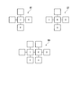
つまり、図7に示したように、表示装置1-1からは、自装置識別情報として“I”が取得され、右側他装置識別情報として“K”が取得され、下側他装置識別情報として“E”が取得される。これにより、表示装置1-1から得られる装置識別情報から、図8に示すような装置識別情報ユニットU1が形成される。なお、装置識別情報ユニット中の空白は、他装置が存在しないことを示す。同様に、表示装置1-2からは、自装置識別情報として“K”が取得され、左側他装置識別情報として“I”が取得され、右側他装置識別情報として“B”が取得され、下側他装置識別情報として“A”が取得される。これにより、表示装置1-2から得られる装置識別情報から、図9に示すような装置識別情報ユニットU2が形成される。
図6は、ステップS5での装置識別情報ユニットの結合処理を示すものである。図6において、位置取得部は、まず、表示装置1-1~1-12それぞれが形成した装置識別情報ユニットから、任意の装置識別情報ユニットを取得する(ステップS101)。次に、位置取得部は、表示装置1-1~1-12それぞれが形成した装置識別情報ユニットから、任意の他の装置識別情報ユニットを取得する(ステップS102)。そして、位置取得部は、取得された2つの装置識別情報ユニットを比較し(ステップS103)、同一の装置識別情報となる部分があるか否かを判定する(ステップS104)。同一の装置識別情報となる部分があれば(ステップS104:Yes)、位置取得部は、同一の装置識別情報となる部分が重なるように、つまり、二つの装置識別情報ユニットにおいて共通する装置識別情報を重複させて結合し、結合装置識別情報ユニットを生成する(ステップS105)。
例えば、図10に示すように、ステップS101で、表示装置1-1からの装置識別情報ユニットU1が取得され、ステップS102で表示装置1-2からの装置識別情報ユニットU2が取得されたとする。この表示装置1-1からの装置識別情報ユニットU1と、表示装置1-2からの装置識別情報ユニットU2とを比較すると、装置識別情報“I”および装置識別情報“K”の部分が同一である。したがって、この場合には、位置取得部は、ステップS105の処理で、図10に示すように、装置識別情報“I”および装置識別情報“K”の部分が重なるように、装置識別情報ユニットを結合して、結合装置識別情報ユニットUAを生成する(ステップS105)。
なお、ステップS104で、同一の装置識別情報となる部分がなければ(ステップS104:No)、結合を保留して(ステップS106)、ステップS102の処理に戻る。
ステップS105で、装置識別情報ユニットを結合して結合装置識別情報ユニットが生成されたら、位置取得部は、全ての装置識別情報ユニットが結合されたか否かを判定する(ステップS107)。全ての装置識別情報ユニットが結合されていなければ(ステップS107:No)、位置取得部は、表示装置1-1~1-12から形成された装置識別情報ユニットから、任意の他の装置識別情報ユニットを取得する(ステップS108)。そして、位置取得部は、取得された装置識別情報ユニットと、結合装置識別情報ユニットとを比較し(ステップS109)、同一の装置識別情報となる部分があるか否かを判定する(ステップS110)。同一の装置識別情報となる部分があれば(ステップS110:Yes)、位置取得部は、同一の装置識別情報となる部分が重なるように、装置識別情報ユニットと結合装置識別情報ユニットとを結合して、新たな結合装置識別情報ユニットを生成して(ステップS111)、ステップS107の処理に戻る。
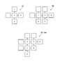
例えば、ステップS108で任意の装置識別情報ユニットを取得した際に、図11に示すように、表示装置1-5からの装置識別情報ユニットU5が取得されたとする。この表示装置1-5からの装置識別情報ユニットU5と、結合装置識別情報ユニットUAとを比較すると、装置識別情報“I”と、装置識別情報“E”と、装置識別情報“A”との部分が同一である。したがって、この場合には、位置取得部は、ステップS111の処理で、図11に示すように、装置識別情報“I”と、装置識別情報“E”と、装置識別情報“A”との部分が重なるように、装置識別情報ユニットを結合して、新たな結合装置識別情報ユニットUA_newを生成する。
なお、ステップS110で、同一の装置識別情報となる部分がなければ(ステップS110:No)、結合を保留して(ステップS112)、ステップS107の処理に戻る。
以下、同様に、位置取得部は、任意の装置識別情報ユニットを取得し(ステップS108)、取得した装置識別情報ユニットと結合装置識別情報ユニットとを比較し(ステップS109)、同一の装置識別情報となる部分があるかを判定する(ステップS110)。そして、位置取得部は、同一の装置識別情報となる部分があれば(ステップS110:Yes)、同一の装置識別情報となる部分が重なるように、装置識別情報ユニットを結合して、新たな結合装置識別情報を生成する(ステップS111)。
以上の処理を繰り返し、全ての装置識別情報ユニットが結合されたら(ステップS107:Yes)、位置取得部は、図5のメイン処理に戻る。そして、位置取得部は、装置識別情報ユニットが結合状態から、マルチ表示システム上での各表示装置の設置位置を判定する(ステップS6)。
図12は、表示装置1-1~1-12の装置識別情報ユニットが全て結合されたときの結合状態を示している。この装置識別情報ユニットの結合状態から、図13に示すように、マルチ表示システムを構成する表示装置のマトリックス数と、各表示装置のマトリックスにおける配置位置(マルチ表示システムにおける表示位置)が求められる。
制御装置2は、マルチ表示システムを構成する表示装置のマトリックス数と、各表示装置のマトリックスにおける配置位置から、各表示装置用の映像信号を作成し、それぞれの表示装置に配信する。あるいは、制御装置2は、マルチ表示システムを構成する表示装置のマトリックス数と、各表示装置のマトリックスにおける配置位置に関する情報を各表示装置に出力し、各表示装置は、入力された映像信号から配置位置に関する情報により自己が表示すべき領域を切り取って表示する。このようにしてマルチ表示システム全体として大画面の画像を表示することができる。
以上説明したように、本発明の実施形態では、表示装置1-1~1-12それぞれの四辺にはNFC通信部20a~20dが設けられ、これにより、四辺に隣接する表示装置間で、装置識別情報を送受することが可能になる。これにより、表示装置1-1~1-12それぞれの装置識別情報を基に、表示装置1-1~1-12の配置を判定することができる。制御装置2は、表示装置1-1~1-12それぞれに、表示位置に応じた各種設定を行うことにより、任意のマトリックス配置により構成したマルチ表示システムにおいて、各表示装置に適切な表示画面を自動的に表示させることができる。また、マルチ表示システムを構成する表示装置のうち、1台を交換した場合は、上記の手順を繰り返すことによって容易に対応することができる。
なお、上述の説明では、複数の表示装置が(M×N)のマトリックスにより構成されるマルチ表示システムの例について説明したが、本実施形態は、表示装置が矩形のマトリックスでない場合にも同様に適用できる。
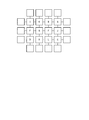
例えば、図14に示すように、13台の表示装置を菱形状に配置してマルチ表示システムを構築した場合、上述と同様に、各表示装置からの自装置および隣接する他装置からの装置識別情報から装置識別情報ユニットを形成して結合していくことにより、図15に示すような結合状態が得られる。この装置識別情報ユニットの結合状態から、図16に示すように、マルチ表示システムを構成する表示装置のマトリックス数と、各表示装置のマルチ表示システムにおける表示位置が求められる。
なお、上述の例では、装置識別情報として、表示装置1-1~1-12それぞれにおいて固有の識別情報を用いたが、装置識別情報として、例えば、製造番号、LANインターフェースのMAC(Media Access Control)アドレス等を使用することができる。
また、上述の例では、4個の通信部としてNFCを用いたが、近距離無線通信規格であれば他の規格に準じたものでもよい。
なお、上述した実施形態である表示装置1の一部、例えば、制御部14の機能をコンピュータで実現するようにしてもよい。この場合、その制御機能を実現するための装置識別情報の処理プログラムをコンピュータ読み取り可能な記録媒体に記録し、この記録媒体に記録された装置識別情報の処理プログラムをコンピュータシステムに読み込ませて、このコンピュータシステムが実行することによって実現してもよい。なお、このコンピュータシステムとは、オペレーティング・システム(Operating System;OS)や周辺装置のハードウェアを含むものである。また、コンピュータ読み取り可能な記録媒体とは、フレキシブルディスク、光磁気ディスク、光ディスク、メモリカード等の可搬型記録媒体、コンピュータシステムに備えられる磁気ハードディスクやソリッドステートドライブ等の記憶装置のことをいう。さらに、コンピュータ読み取り可能な記録媒体とは、インターネット等のコンピュータネットワーク、および電話回線や携帯電話網を介してプログラムを送信する場合の通信回線のように、短時間の間、動的にプログラムを保持するもの、さらには、その場合のサーバ装置やクライアントとなるコンピュータシステム内部の揮発性メモリのように、一定時間プログラムを保持するものを含んでもよい。また上記の装置識別情報の処理プログラムは、前述した機能の一部を実現するためのものであってもよく、さらに、前述した機能をコンピュータシステムにすでに記録されているプログラムとの組み合わせにより実現するものであってもよい。
以上、本発明の実施の形態について図面を参照して詳述したが、具体的な構成はその実施形態に限られるものではなく、本発明の要旨を逸脱しない範囲の設計等も含まれる。
1-1~1-12 表示装置
2 制御装置
11 入力インターフェース
12 映像処理部
13 表示パネル
14 制御部
15 メモリ
16 識別情報記憶領域
17 出力インターフェース
18 通信インターフェース
20a~20d NFC通信部
101-1~101-5 表示装置
114 制御部
116 識別情報記憶部
120a~120d 通信部
2 制御装置
11 入力インターフェース
12 映像処理部
13 表示パネル
14 制御部
15 メモリ
16 識別情報記憶領域
17 出力インターフェース
18 通信インターフェース
20a~20d NFC通信部
101-1~101-5 表示装置
114 制御部
116 識別情報記憶部
120a~120d 通信部
Claims (6)
- マルチ表示システムに用いられる表示装置において、
自装置識別情報を記憶する識別情報記憶部と、
当該表示装置の上下左右の端部にそれぞれ設けられた4個の通信部と、
通信インターフェースと、
前記識別情報記憶部から読み出した前記自装置識別情報を前記4個の通信部を介して出力させるとともに、隣接配置された他の表示装置から前記通信部を介して前記他の表示装置の識別情報である他装置識別情報を取り込み、前記自装置識別情報と前記他装置識別情報とを、前記通信インターフェースを介して出力させる制御部と、
を備える表示装置。 - 前記4個の通信部それぞれは、無線通信により前記隣接配置された他の表示装置との間で、前記自装置識別情報を送信し、前記他装置識別情報を受信する、
請求項1記載の表示装置。 - 前記制御部は、前記隣接配置された他の表示装置における前記他装置識別情報を前記他の表示装置の隣接方向と関連付けて出力する、
請求項1または請求項2いずれか記載の表示装置。 - 複数の表示装置で構成されるマルチ表示システムにおいて、
前記複数の表示装置それぞれが、
自装置識別情報を記憶する識別情報記憶部と、
当該表示装置の上下左右の端部にそれぞれ設けられた4個の通信部と、
通信インターフェースと、
前記識別情報記憶部から読み出した前記自装置識別情報を前記4個の通信部を介して出力させるとともに、隣接配置された他の表示装置から前記通信部を介して前記他の表示装置の識別情報である他装置識別情報を取り込み、前記自装置識別情報と前記他装置識別情報とを、前記通信インターフェースを介して出力させる制御部と、
前記自装置識別情報と前記他装置識別情報とに基づいて、前記マルチ表示システムにおける前記複数の表示装置それぞれの表示位置を取得する位置取得部と、
を備えるマルチ表示システム。 - 前記位置取得部は、前記自装置識別情報と前記他装置識別情報とに基づいて生成された装置識別情報ユニットを結合し、前記結合された装置識別情報ユニットの連結状態から、前記マルチ表示システムにおける前記複数の表示装置それぞれの位置を取得する、
請求項4記載のマルチ表示システム。 - マルチ表示システムにおける複数の表示装置の設置位置検出方法において、
前記複数の表示装置それぞれから、
自表示装置における自装置識別情報と前記自表示装置に隣接配置された他の表示装置における他装置識別情報とを取得する取得ステップと、
前記複数の表示装置それぞれから取得した前記自装置識別情報と前記他装置識別情報とに基づいて、前記マルチ表示システムにおける前記複数の表示装置それぞれの表示位置を取得する取得ステップと、
を有する設置位置検出方法。
Priority Applications (1)
| Application Number | Priority Date | Filing Date | Title |
|---|---|---|---|
| PCT/JP2013/051593 WO2014115302A1 (ja) | 2013-01-25 | 2013-01-25 | 表示装置、マルチ表示システム、および設置位置検出方法 |
Applications Claiming Priority (1)
| Application Number | Priority Date | Filing Date | Title |
|---|---|---|---|
| PCT/JP2013/051593 WO2014115302A1 (ja) | 2013-01-25 | 2013-01-25 | 表示装置、マルチ表示システム、および設置位置検出方法 |
Publications (1)
| Publication Number | Publication Date |
|---|---|
| WO2014115302A1 true WO2014115302A1 (ja) | 2014-07-31 |
Family
ID=51227117
Family Applications (1)
| Application Number | Title | Priority Date | Filing Date |
|---|---|---|---|
| PCT/JP2013/051593 Ceased WO2014115302A1 (ja) | 2013-01-25 | 2013-01-25 | 表示装置、マルチ表示システム、および設置位置検出方法 |
Country Status (1)
| Country | Link |
|---|---|
| WO (1) | WO2014115302A1 (ja) |
Cited By (1)
| Publication number | Priority date | Publication date | Assignee | Title |
|---|---|---|---|---|
| JP2025092793A (ja) * | 2024-04-02 | 2025-06-20 | 任天堂株式会社 | ゲームシステム、および、ゲーム処理方法 |
Citations (4)
| Publication number | Priority date | Publication date | Assignee | Title |
|---|---|---|---|---|
| JPH10333631A (ja) * | 1997-06-02 | 1998-12-18 | Daichiyuu Denshi:Kk | 拡張型表示装置および拡張型表示装置を用いた表示システム |
| JP2003280624A (ja) * | 2002-03-27 | 2003-10-02 | Sony Corp | マルチディスプレイ装置、画像表示装置、および方法、並びにコンピュータ・プログラム |
| JP2005301131A (ja) * | 2004-04-15 | 2005-10-27 | Sony Corp | サーバ装置、表示装置及び表示方法 |
| JP2009103728A (ja) * | 2007-10-19 | 2009-05-14 | Seiko Epson Corp | 表示システム、表示装置、表示ユニット、及び、表示システムの制御方法 |
-
2013
- 2013-01-25 WO PCT/JP2013/051593 patent/WO2014115302A1/ja not_active Ceased
Patent Citations (4)
| Publication number | Priority date | Publication date | Assignee | Title |
|---|---|---|---|---|
| JPH10333631A (ja) * | 1997-06-02 | 1998-12-18 | Daichiyuu Denshi:Kk | 拡張型表示装置および拡張型表示装置を用いた表示システム |
| JP2003280624A (ja) * | 2002-03-27 | 2003-10-02 | Sony Corp | マルチディスプレイ装置、画像表示装置、および方法、並びにコンピュータ・プログラム |
| JP2005301131A (ja) * | 2004-04-15 | 2005-10-27 | Sony Corp | サーバ装置、表示装置及び表示方法 |
| JP2009103728A (ja) * | 2007-10-19 | 2009-05-14 | Seiko Epson Corp | 表示システム、表示装置、表示ユニット、及び、表示システムの制御方法 |
Cited By (1)
| Publication number | Priority date | Publication date | Assignee | Title |
|---|---|---|---|---|
| JP2025092793A (ja) * | 2024-04-02 | 2025-06-20 | 任天堂株式会社 | ゲームシステム、および、ゲーム処理方法 |
Similar Documents
| Publication | Publication Date | Title |
|---|---|---|
| US12154490B2 (en) | Modular display apparatus and control method thereof | |
| EP3752907B1 (en) | Modular display apparatus and method for controlling thereof | |
| JP5677034B2 (ja) | 表示装置及びその制御方法、情報処理装置及びその制御方法、画像表示システム、プログラム | |
| KR102756660B1 (ko) | 월(wall) 디스플레이를 구성하는 디스플레이 장치 및 이의 제어 방법 | |
| US10002105B2 (en) | Display device | |
| US20150205565A1 (en) | Multi-screen display system and display method | |
| KR101786319B1 (ko) | 멀티 비전 장치 | |
| KR100922116B1 (ko) | 멀티 디스플레이 장치 통합 시스템 및 그 방법 | |
| JP2012019442A (ja) | プロジェクタシステムおよびプロジェクタ | |
| JP5641795B2 (ja) | 大型映像表示装置 | |
| WO2021116688A1 (en) | Master/slave modular display system | |
| CN111742360A (zh) | 图像显示装置和图像显示方法 | |
| US20120194411A1 (en) | Radio apparatus, display apparatus and reception control method | |
| US9491209B2 (en) | Wireless image transmission and reception system and method therefor | |
| JP2009103728A (ja) | 表示システム、表示装置、表示ユニット、及び、表示システムの制御方法 | |
| WO2014115302A1 (ja) | 表示装置、マルチ表示システム、および設置位置検出方法 | |
| US12468496B2 (en) | Media docking device and media docking method | |
| WO2016170596A1 (ja) | 表示装置、マルチ表示システム、分割映像表示方法、およびプログラム | |
| WO2014010059A1 (ja) | 画像表示装置、画像表示システム及び画像表示方法 | |
| WO2025262852A1 (ja) | 電子機器およびその制御方法 | |
| CN104679461A (zh) | 显示处理方法及装置、显示系统 | |
| JP2016009075A (ja) | マルチディスプレイシステム、表示装置、位置特定方法、コンピュータプログラム、及び記録媒体 | |
| JP2016122873A (ja) | 通信装置及び通信方法 | |
| TWM531704U (zh) | 數位視訊錄影機、攝影機以及錄影系統 |
Legal Events
| Date | Code | Title | Description |
|---|---|---|---|
| 121 | Ep: the epo has been informed by wipo that ep was designated in this application |
Ref document number: 13873006 Country of ref document: EP Kind code of ref document: A1 |
|
| NENP | Non-entry into the national phase |
Ref country code: DE |
|
| 122 | Ep: pct application non-entry in european phase |
Ref document number: 13873006 Country of ref document: EP Kind code of ref document: A1 |
|
| NENP | Non-entry into the national phase |
Ref country code: JP |