WO2014115290A1 - 信号処理装置・音響処理システム - Google Patents
信号処理装置・音響処理システム Download PDFInfo
- Publication number
- WO2014115290A1 WO2014115290A1 PCT/JP2013/051520 JP2013051520W WO2014115290A1 WO 2014115290 A1 WO2014115290 A1 WO 2014115290A1 JP 2013051520 W JP2013051520 W JP 2013051520W WO 2014115290 A1 WO2014115290 A1 WO 2014115290A1
- Authority
- WO
- WIPO (PCT)
- Prior art keywords
- converter
- time
- acoustic echo
- signal
- speech waveform
- Prior art date
- Legal status (The legal status is an assumption and is not a legal conclusion. Google has not performed a legal analysis and makes no representation as to the accuracy of the status listed.)
- Ceased
Links
Images




Classifications
-
- G—PHYSICS
- G10—MUSICAL INSTRUMENTS; ACOUSTICS
- G10L—SPEECH ANALYSIS TECHNIQUES OR SPEECH SYNTHESIS; SPEECH RECOGNITION; SPEECH OR VOICE PROCESSING TECHNIQUES; SPEECH OR AUDIO CODING OR DECODING
- G10L21/00—Speech or voice signal processing techniques to produce another audible or non-audible signal, e.g. visual or tactile, in order to modify its quality or its intelligibility
- G10L21/02—Speech enhancement, e.g. noise reduction or echo cancellation
- G10L21/0208—Noise filtering
-
- H—ELECTRICITY
- H04—ELECTRIC COMMUNICATION TECHNIQUE
- H04M—TELEPHONIC COMMUNICATION
- H04M3/00—Automatic or semi-automatic exchanges
- H04M3/42—Systems providing special services or facilities to subscribers
- H04M3/56—Arrangements for connecting several subscribers to a common circuit, i.e. affording conference facilities
-
- H—ELECTRICITY
- H04—ELECTRIC COMMUNICATION TECHNIQUE
- H04M—TELEPHONIC COMMUNICATION
- H04M9/00—Arrangements for interconnection not involving centralised switching
- H04M9/08—Two-way loud-speaking telephone systems with means for conditioning the signal, e.g. for suppressing echoes for one or both directions of traffic
- H04M9/082—Two-way loud-speaking telephone systems with means for conditioning the signal, e.g. for suppressing echoes for one or both directions of traffic using echo cancellers
-
- G—PHYSICS
- G10—MUSICAL INSTRUMENTS; ACOUSTICS
- G10L—SPEECH ANALYSIS TECHNIQUES OR SPEECH SYNTHESIS; SPEECH RECOGNITION; SPEECH OR VOICE PROCESSING TECHNIQUES; SPEECH OR AUDIO CODING OR DECODING
- G10L21/00—Speech or voice signal processing techniques to produce another audible or non-audible signal, e.g. visual or tactile, in order to modify its quality or its intelligibility
- G10L21/02—Speech enhancement, e.g. noise reduction or echo cancellation
- G10L21/0208—Noise filtering
- G10L2021/02082—Noise filtering the noise being echo, reverberation of the speech
-
- H—ELECTRICITY
- H04—ELECTRIC COMMUNICATION TECHNIQUE
- H04M—TELEPHONIC COMMUNICATION
- H04M3/00—Automatic or semi-automatic exchanges
- H04M3/002—Applications of echo suppressors or cancellers in telephonic connections
Definitions
- An acoustic echo canceller that removes acoustic echo components mixed in a digital signal obtained via a microphone and an A / D converter from sound radiated to the space via a D / A converter and a speaker has been widely used.
- a general acoustic echo canceller is based on the premise that the same clock is supplied to the A / D converter and the D / A converter.
- the original signal of the sound radiated in the air through the D / A converter is described as d (t).
- t is a time index.
- the sound obtained through the A / D converter is described as x (t).
- s (t) is a signal composed of speakers and noise in the environment. * Is an operator representing convolutional mixing. Let h be a transfer function that travels through walls and floors in the environment before the sound from the speaker is received by the microphone. In general, h cannot be known in advance because it depends on the environment. On the other hand, d (t) is a signal held by the system before being sent to the D / A converter, and can be considered to be known.
- s (t) contained in x (t) is extracted, s (t) is transferred to the connection destination, and radiated from the speaker at the connection destination. Can deliver voice. Therefore, the point is how to extract s (t) from x (t). If h is known, s (t) extracts h * d (t) from x (t) by subtraction. can do.
- the acoustic echo canceller takes a configuration in which h is estimated from x (t) and d (t) by some method, and s (t) is estimated using the obtained h.
- the conventional acoustic echo canceller is designed on the assumption that the A / D converter and the D / A converter operate in an environment where signals are sampled at the same timing. Therefore, when the sampling timings of the A / D converter and the D / A converter are shifted, the acoustic echo component removal performance of the acoustic echo canceller is deteriorated.
- a sampling timing difference between the A / D converter and the D / A converter for example, when a TV built-in D / A converter and a speaker are connected, the remote conference system uses it for speaker playback. It is often the case that the signal is output with a delay of several hundred ms after the signal is output.
- the time lag between the D / A converter and the A / D converter will change from time to time.
- the sampling rate of the D / A converter and A / D converter is set to the same 8 kHz, it is very rare that the same sampling rate is obtained unless the same clock is supplied. is there.
- the sampling rate slightly shifts such that the other has a sampling rate of 8001 Hz.
- the sampling rate is considered to be specific to the device that generates the clock (such as crystal), it is considered that the sampling rate is constant for each time for each D / A converter and A / D converter. Therefore, the D / A converter and the A / D converter are considered to be out of time in proportion to the time.
- Fig. 4 shows the values when the correlation coefficient between the sound recorded by the A / D converter and the sound recorded by the D / A converter is calculated for each hour.
- the horizontal axis is the time axis
- the vertical axis shows the time lag between the D / A converter and the A / D converter. It can be seen that the time lag between the D / A converter and the A / D converter increases in proportion to the time. Therefore, in Patent Document 1, the acoustic echo component cannot be accurately removed due to the time shift between the D / A converter and the A / D converter proportional to the time.
- This invention makes it a subject to remove an acoustic echo component when there is a time lag between each D / A converter and each A / D converter proportional to time.
- the adaptive acoustic echo canceller based on an adaptive filter such as the conventional LMS algorithm can adaptively estimate the transfer function until the signal after D / A conversion reaches the A / D converter.
- a time shift proportional to time is considered to be included in this transfer function, but in general, a time shift proportional to time is so early that several samples are shifted in a few seconds. This adaptive filter cannot follow up (see FIG. 4).
- a time shift coefficient estimation unit characterized by estimating a time proportional coefficient of time shift is limited to a time shift that occurs in proportion to time, and an acoustic echo canceller using an adaptive filter is used in combination.
- the present invention makes it possible to make a comfortable voice call with clear voice with little influence of acoustic echo in a video conference system for connecting large rooms.
- acoustic echo canceller using a general adaptive filter it is possible to follow with high accuracy even when a fast time-proportional time shift that cannot be theoretically followed occurs. .
- the present invention is assumed to be used in, for example, a remote conference system used in a large room.
- An example for implementing the present invention in a remote conference is shown in FIG.
- FIG. 1 shows an example of a hardware configuration of a conference system installed at each remote conference site.
- the microphone 105 may not be a single microphone, but may be a microphone array composed of, for example, a plurality of microphone elements.
- the collected analog voice waveform is converted from an analog signal to a digital signal by the A / D converter 104.
- the converted digital speech waveform is subjected to dereverberation processing in the central processing unit 102, and then converted into a packet via the HUB 108 and released to the network.
- the central processing unit 102 reads a program stored in the nonvolatile memory 101 and parameters used in the program, and executes the program.
- a work memory used when executing the program is secured on the volatile memory 103, and storage areas for various parameters necessary for acoustic processing are defined.
- the central processing unit 102 receives the voice waveform of the other base (far end) in the remote conference from the HUB 108 via the network.
- the received far-end speech waveform (digital speech waveform) is sent to the D / A converter 106 via the central processing unit 102, converted from a digital signal to an analog signal, and then converted into an analog speech waveform.
- the speaker 107 may not be a single speaker element but may be composed of, for example, a plurality of speaker elements.
- the video information for each site is captured by a general camera 109 and transmitted to another site via the HUB 108.
- the video information of other bases is sent to the HUB 108 via the network, and further displayed on the display 110 installed at each base via the central processing unit 102.
- a configuration in which a plurality of cameras 109 or a plurality of displays 110 are installed may be employed.
- the user interface 111 controls connection and disconnection of the remote conference system.
- the user interface 111 is assumed to be one commonly used by those skilled in the art, such as a mouse, a keyboard, or an infrared remote controller.
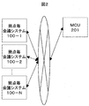
- FIG. 2 shows an example of a configuration in which a conference system at each site is connected in the remote conference system.
- Each of the N conference systems (100-1, 100-2,... 100-N), where N is the number of sites, is connected by a network and connected to the MCU 202 that controls the flow of audio and video. The flow of audio and video at each site is controlled. Since the MCU is a known system for those skilled in the art, the description is omitted.
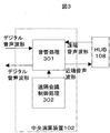
- FIG. 3 shows a block configuration of an acoustic processing program executed in the central processing unit 102.
- a digital speech waveform obtained from the microphone 105 via the A / D converter 104 is processed by an acoustic processing 301.
- the acoustic processing 301 removes an acoustic echo component from the digital speech waveform, and picks up and outputs a near-end speech utterance in each conference room.
- the acoustic echo component refers to a component mixed in the microphone 105 after the sound waveform output from the speaker 107 is reflected by the wall or ceiling of each site.
- the acoustic processing 301 uses a far-end speech waveform obtained via the HUB 108 in order to remove acoustic echo components.
- the remote conference control processing 302 is a block that performs processing related to control of the remote conference system, such as start and end of a remote conference, and selection of a connection destination. Since the remote conference control process 302 is a remote conference control process that can be easily inferred by those skilled in the art, a detailed description of the configuration is omitted.
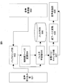
- FIG. 5 shows a detailed block configuration of the acoustic processing 301.
- the voice capturing unit 501 captures the microphone input signal x (t) at each time.
- t is the sample number for A / D conversion.
- the audio receiving unit 502 receives a speaker reproduction signal d (t) transmitted from the connection destination to which the remote conference system is connected from the HUB 108.
- a signal d (t) for speaker reproduction is radiated from the speaker 107 via the D / A converter 104.
- the buffering unit 503 has a predetermined amount of the microphone input signal x (t) captured by the audio capturing unit 501 and the signal d (t) for speaker reproduction captured by the audio receiving unit 502, either a volatile memory 103 or a non-volatile memory. Store in 101.
- the microphone input signal x (t) buffered by the buffering unit 503 and the speaker reproduction signal d (t) are subjected to short-time Fourier transform to obtain a time frequency.
- the obtained time-frequency domain signals are expressed as x (f, ⁇ ) and d (f, ⁇ ).
- x (f, ⁇ ) is a signal after the short-time Fourier transform of the microphone input signal x (t)
- d (f, ⁇ ) is after the short-time Fourier transform of the signal d (t) t for speaker reproduction.
- f is a frequency index
- ⁇ is a frame index of short-time Fourier transform.
- the filter learning unit 505 is a time-frequency domain signal or a time-shift proportionality coefficient proportional to the time between the filter h for acoustic echo removal and the time between the D / A converter and the A / D converter. Learn with a.
- the learning method of the proportional coefficient a of the time deviation proportional to the time between the filter h for acoustic echo removal, the D / A converter and the A / D converter is as follows: Different depending on learning from time-frequency domain signal.
- the learned acoustic echo filter h and the proportional coefficient a of the time deviation proportional to the time between the D / A converter and the A / D converter are secured on the volatile memory 103 or the nonvolatile memory 101. It is stored in the filter DB 506.
- the acoustic echo canceller unit 507 uses the acoustic echo removal filter h learned by the filter learning unit 505 and the proportional coefficient a of the time shift proportional to time to emit radiation from the speaker included in the microphone input signal x (t). Remove components and extract near-end speech. Also in the acoustic echo canceller 507, processing is divided depending on whether the acoustic echo component is removed from the time domain signal or the acoustic echo component is removed from the time frequency domain signal.
- the acoustic echo canceller unit 507 convolves the acoustic echo removal filter h with the speaker reproduction signal d (t) or d (f, ⁇ ), thereby obtaining the microphone input signal x (
- the estimated value e (t) or e (f, ⁇ ) of the acoustic echo component in t) is estimated, and this is subtracted from the microphone input signal x (t) or x (f, ⁇ ). Remove.
- the time frequency domain signal after the acoustic echo component is removed in the acoustic echo canceller is converted into a time domain signal.
- the audio transmission unit 509 transmits the time domain signal after the acoustic echo component removal to the connection destination.
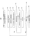
- FIG. 6 shows that the filter learning unit 505 learns from the time domain signal a filter h for acoustic echo removal, a proportional coefficient a of time deviation proportional to the time between the D / A converter and the A / D converter. It is the figure which showed the processing flow at the time.
- the filter unit may be configured to operate every time one time domain signal is obtained, or may be configured to operate every time a plurality of samples are obtained.
- This configuration is an extended configuration of an LMS (Least Mean Square) algorithm or a RLS (Recursive Least Square) algorithm, which is a kind of adaptive filter of a conventional acoustic echo canceller.
- LMS Local Mean Square
- RLS Recursive Least Square
- the filter learning unit 505 determines an update rate ⁇ that is a rate of change when the filter is changed over time and a filter length L of the acoustic echo removal filter h. Further, the minimum value and the maximum value of the search range when the proportionality coefficient a is optimized in an exploratory manner are determined as amin and amax, respectively.
- the step size when searching for the proportionality coefficient a is set to da (601). In this processing flow, the best value is selected when the proportionality coefficient a is changed from the minimum value amin to the maximum value amax.
- the provisional proportional coefficient a used for the search is a2.
- the temporary proportional coefficient a2 is set as amin (602).
- dd (t) can be generated by multiplying the original d (t) by a sync function or performing sampling rate conversion (603). Since this is a method well known to those skilled in the art, a detailed description is omitted.
- the filter htemp is obtained by a weighted least square method as shown in Equation 1. A person skilled in the art can easily calculate this weighted least squares solution. Also, the error at that time is represented by err shown in Equation 2.
- the filter learning unit 505 learns from the time domain signal the filter h for acoustic echo removal and the proportional coefficient a of the time deviation proportional to the time between the D / A converter and the A / D converter. .
- FIG. 7 is a diagram showing a processing flow in the filter learning unit 505 for obtaining a time-shift proportional coefficient a and an acoustic echo removal filter h from a time-frequency domain signal.
- an update rate ⁇ which is a rate of change when the filter is changed every time
- a filter length L a frame width Lf of short-time Fourier transform
- a frame shift Ls are determined (701).
- the microphone input signal x (f, ⁇ ) in the time frequency domain and the reference signal d (f, ⁇ ) are calculated by short-time Fourier transform (702).
- a provisional value is input to the proportional coefficient a (for example, 0) (703).
- the least square solution of the filter is obtained by Equation 3 (704).
- Equation 4 the estimated value e (f, ⁇ ) of the acoustic echo component is defined by Equation 4.
- Equation 5 the normalized phase difference between e (f, ⁇ ) and x (f, ⁇ ) is calculated by Equation 5 (705).
- H is an operator for taking conjugate transpose
- arg is an operator for calculating the phase difference of complex numbers.
- the filter learning unit 505 obtains the proportional coefficient a and the acoustic echo removal filter h that are proportional to time from the signal in the time-frequency domain.
- FIG. 8 shows an operation flowchart of the remote conference system in the present invention when learning a time-shift proportional coefficient proportional to time when the remote conference system is started up.
- the A / D converter 104 and the D / A converter 106 first start sampling (801).
- the central processing unit 102 calculates a time deviation proportional coefficient a proportional to time by the filter learning in the time domain or time frequency domain described above (802).
- the calculated proportionality coefficient a is stored in the filter DB. It is necessary to make a sound from the D / A converter when calculating the time deviation proportional coefficient a proportional to the time, but this does not necessarily have to be a remote sound, but a sound prepared in advance in the remote conference system. It is also possible to take a configuration that reproduces.
- a remote conference is started by connecting to a remote place (803).
- the filter learning unit 505 of the acoustic processing 301 calculates the time-shift proportional coefficient a in 802 at 802, the remote conference control processing 302 starts the remote conference start control.
- a speaker playback signal d (t) reference signal
- a microphone input signal x (t) is received (805).
- the acoustic echo canceller unit 507 corrects the received reference signal d (t) to d (t-at) using a time shift coefficient a proportional to the time calculated in step 802 in advance (806). ).
- the reference signal d (t) is corrected by a method well known to those skilled in the art, such as superimposing the sync function on the waveform or converting the sampling rate.
- dd (t) is converted into a time-frequency domain signal dd (f, ⁇ ).
- the filter learning unit 505 sequentially updates the acoustic echo canceller filter h by a method such as LMS or RLS, using dd instead of d as a reference signal.
- the acoustic echo canceller filter h is updated in the time domain or the time frequency domain (807).
- the acoustic echo canceller 507 superimposes the obtained filter h on the reference signal dd (t), creates an acoustic echo replica, and subtracts the created acoustic echo replica from the microphone input signal x (t). , A signal from which acoustic echo components are removed is obtained.
- the inverse Fourier transform 508 a signal after removal of echo components in the time domain is obtained by inverse Fourier transform (808).
- the voice transmission unit 508 transmits the signal after the acoustic echo component removal to the connection destination via the HUB (809).
- the remote conference control process 302 ends the process, and otherwise returns to the reception of the reference signal (804).
- FIG. 9 is a flowchart when the present invention is used so that the time lag coefficient proportional to the time for each connection configuration is reset when the microphone or speaker used in the teleconference system is switched.
- the A / D converter 104 and the D / A converter 106 first start sampling (901).
- the filter learning unit 505 calculates a time shift coefficient a proportional to time by the filter learning in the time domain or the time frequency domain described above (902). This a is used as an initial value. And it connects with a remote place and a remote conference is started (903).
- the filter learning unit 505 determines whether the connection between the A / D converter 104 and the D / A converter 106 has changed. If it has changed, the process proceeds to a resetting (905).
- the A / D converter 104, the D / A converter 106 connected, and the time shift proportional coefficient a proportional to the time corresponding to each sampling rate are shown on the filter DB as shown in FIG. It has a simple data structure.
- the filter learning unit 505 refers to the table of FIG.
- the time shift proportional coefficient a proportional to the time corresponding to the / D converter 104 and D / A converter 106 and their sampling rates is used as the time shift proportional coefficient a proportional to the new time.
- the filter learning unit 505 performs a by performing filter learning in the time domain or time frequency domain described above. Ask. If the connection relationship between the A / D converter and D / A converter has not changed, the voice communication status of the normal remote conference is entered.
- the acoustic echo canceller first corrects the reference signal each time a speaker playback signal (reference signal) sent from a remote location is received (906) and a microphone input signal is acquired (907).
- the obtained reference signal is corrected as d (t-at) using a time shift coefficient a proportional to the time calculated in advance.
- the correction is performed by a method well known to those skilled in the art, such as superimposing the sync function on the waveform or converting the sampling rate.
- dd (t) is converted into a time-frequency domain signal dd (f, ⁇ ).
- the filter learning unit sequentially updates the acoustic echo canceller filter h by a method such as LMS or RLS, using dd instead of d as a reference signal.
- the update is performed in the time domain or the time frequency domain (909).
- the acoustic echo canceller unit superimposes the obtained filter h on the reference signal, creates an acoustic echo replica, and subtracts the created acoustic echo replica from the microphone input signal to obtain the signal from which the acoustic echo component has been removed. obtain.
- a signal after removal of the acoustic echo component in the time domain is obtained by inverse Fourier transform (910).
- the voice transmission unit 509 transmits the signal after the acoustic echo component removal to the connection destination via the HUB (911). If the remote conference system is terminated by user control via the user interface, the process is terminated. Otherwise, the process returns to the connection switching determination (804).
- FIG. 11 shows an embodiment of a remote conference system using a speaker with a D / A converter and a microphone with an A / D converter.
- a digital signal not an analog signal, is input or output to the speaker 1101 with the D / A conversion function and the wireless microphone 1102 with the A / D conversion function in which the D / A conversion function is incorporated. Therefore, they are sampled with different clocks.
- the voice receiving unit 1106 receives the voice signal transmitted from the remote conference system at the connection destination via the HUB 108.
- the received audio signal is sent to a speaker 1101 with a D / A conversion function in which a D / A conversion function is incorporated by a speaker reproduction 1105 and reproduced.
- the wireless receiver 1103 receives a microphone input signal recorded by the wireless microphone 1102 with an A / D conversion function.
- the acoustic echo canceller 1104 removes the acoustic echo component of the audio reproduced from the speaker 1101 with the D / A conversion function, which is included in the microphone input signal and has the D / A conversion function. The removal is performed while correcting the time shift proportional to the time by the configuration shown in the first embodiment of the present invention.
- the audio transmission unit 1107 transmits the signal after the acoustic echo canceller to a remote place via the HUB 108.
- the acoustic echo canceller 1104 performs the same processing as the acoustic processing
- 100 Conference system at each site, 101: Non-volatile memory, 102: Central processing unit, 103 ... Volatile memory, 104 ... A / D converter, 105 ... Microphone, 106 ... D / A converter, 107 ... Speaker, 108 ... HUB, 109 ... Camera, 110 ... Display, 110 ... User interface, 201 ... MCU, 301 ... Sound processing, 302 ... Remote conference control processing, 501 ... Audio capture unit, 502 ... Audio reception unit, 503 ... Buffering, 504 ... short-time Fourier transform, 505 ... filter learning unit, 506 ... filter DB, 507 ... acoustic echo canceller, 508 ... short-time Fourier transform, 509 ...
- voice transmission unit 1101 ... speaker with D / A conversion function, 1102 ... A / Wireless microphone with D conversion function, 1103 ... wireless receiver, 1104 ... acoustic echo canceller, 1105 ... speaker playback, 1106 ... audio receiver, 1107 ... audio transmitter
Landscapes
- Engineering & Computer Science (AREA)
- Signal Processing (AREA)
- Multimedia (AREA)
- Quality & Reliability (AREA)
- Health & Medical Sciences (AREA)
- Audiology, Speech & Language Pathology (AREA)
- Human Computer Interaction (AREA)
- Physics & Mathematics (AREA)
- Acoustics & Sound (AREA)
- Computational Linguistics (AREA)
- Cable Transmission Systems, Equalization Of Radio And Reduction Of Echo (AREA)
- Telephone Function (AREA)
- Circuit For Audible Band Transducer (AREA)
- Telephonic Communication Services (AREA)
Abstract
従来の音響エコーキャンセラでは,A/D変換機とD/A変換機の間でサンプリングレートがずれていることに起因する時間に比例した時間ずれが起こる場合に、高精度にエコー成分を除去することが困難であった。 本発明では,時間に比例して起こる時間ずれの比例係数を推定する時間ずれ係数推定部を有し,更に本推定部が出力する時間ずれ係数を使用して音響エコー成分を除去することを特徴とする音響エコーキャンセラにより,時間に比例した時間ずれが起こる場合でも,高精度に音響エコー成分を除去できる。
Description
A/D変換機でデジタル変換した後の信号から,D/A変換機で出力した信号成分が,何らかの要因によりA/D変換機でデジタル変換した後の信号に混入するような信号処理系において,該混入成分を除去する信号処理除去装置,もしくは音響エコーキャンセラ技術に属する。
D/A変換機及びスピーカ経由で空間に放射した音がマイクロホン及びA/D変換機経由で得られるデジタル信号に混入する音響エコー成分を除去する音響エコーキャンセラが広く用いられてきている。一般的な音響エコーキャンセラは,A/D変換機とD/A変換機に同一のクロックが供給されていることを前提としている。D/A変換機を通して空中に放射する音の原信号をd(t)と記載する。ここで,tは時間インデックスとする。更にA/D変換機を通して得られる音をx(t)と記載する。ここで,x(t)は,一般に,x(t)=h*d(t)+s(t)と記述することができる。ここで,s(t)は環境内にいる話者や雑音からなる信号とする。*は畳み込み混合を表す演算子とする。hは,スピーカから出た音がマイクロホンで受音されるまでに環境内の壁や床などを伝わる伝達関数とする。一般にhは環境に依存するため事前に知ることはできない。一方,d(t)は、D/A変換機に出す前にシステムが保持している信号であり,既知であると考えることができる。
遠隔会議システムでは,x(t)の中に含まれるs(t)を抽出し,s(t)を接続先に転送し,接続先のスピーカより放射することで相手に環境内の話者の声を届けることができる。したがってs(t)を如何にx(t)から抽出するかがポイントとなるが,hがもし分かっていれば,s(t)はx(t)からh*d(t)を引き算により抽出することができる。
音響エコーキャンセラは、x(t)とd(t)から何らかの方法でhを推定し,得られたhを使ってs(t)を推定する構成を取る。hの推定法としては,e(t)=x(t)-h*d(t)で定義されるe(t)の分散値の期待値E[e(t)*e(t)]ができる限り小さくなるように推定する最小二乗法に基づくLMS(Least Mean Square)法などが一般に使われている。
従来の音響エコーキャンセラでは,A/D変換機とD/A変換機において,信号が同じタイミングでサンプリングされている環境で動作することを前提に設計されている。したがって,A/D変換機とD/A変換機のサンプリングのタイミングがずれる場合には,音響エコーキャンセラの音響エコー成分除去性能が低下することが問題となっていた。A/D変換機とD/A変換機のサンプリングのタイミングのずれとして,例えばテレビ内蔵のD/A変換機とスピーカとを接続しているような場合においては,遠隔会議システムにおいて,スピーカ再生用の信号を出力した後,該信号が数百ms遅れで出力されることがよく起こる。このような時間タイミングがスピーカで遅れる場合には,遅れ時間分のオフセットを加味した音響エコーキャンセラにより,遅れの影響無く音響エコー成分が除去できる構成が示されている(例えば,特許文献1参照)。
しかし,D/A変換機とA/D変換機が同じクロックで駆動されていない場合においては,D/A変換機とA/D変換機の間の時間ずれは時間毎に変化することになる。例えば,D/A変換機とA/D変換機のサンプリングレートが同じ8kHzに設定されている場合であっても,同じクロックを供給されていない限り,同じサンプリングレートとなることは非常にまれである。通常、一方がサンプリングレート8000Hzである場合でも,他方がサンプリングレート8001Hzといったように微小にサンプリングレートがずれることになる。
一方,サンプリングレートは,クロックを生成するデバイス(例えば水晶など)に固有であると考えられるため, D/A変換機とA/D変換機毎に,時間毎に一定のレートとなると考えられる。したがって,D/A変換機とA/D変換機は時間に比例して時間がずれることになると考えられる。
図4にA/D変換機で収録した音とD/A変換機で収録した音との間の相関係数を時間毎に算出した時の値を示す。横軸は時間軸であり,縦軸はD/A変換機とA/D変換機との間の時間ずれを示している。時間に比例してD/A変換機とA/D変換機との間の時間ずれが大きくなっている様子が見て取れる。よって、特許文献1では、このような時間に比例したD/A変換機とA/D変換機毎の間の時間ずれにより、音響エコー成分を精度よく除去することが出来ない。
本発明は、時間に比例したD/A変換機とA/D変換機毎の間の時間ずれがある場合における音響エコー成分の除去を課題とする。
従来のLMSアルゴリズムなどの適応フィルタに基づく適応型の音響エコーキャンセラでは,D/A変換後の信号がA/D変換機に届くまでの伝達関数を適応的に推定することができる。理論上は、時間に比例する時間ずれは,この伝達関数に含まれると考えられるが,一般に時間に比例する時間ずれは数秒の間に数サンプルもずれるような非常に早いずれであるため,一般の適応型フィルタでは追従が追いつかない(図4参照)。
本発明では,時間に比例して起こる時間ずれに限定し,時間ずれの時間比例係数を推定することを特徴とする時間ずれ係数推定部と適応型フィルタによる音響エコーキャンセラとを併用する。
本発明により広い部屋同士をつなぐビデオ会議システムにおいて,音響エコーの影響が少ないクリアな音声で快適な音声通話が可能となる。また、一般の適応型フィルタを用いた音響エコーキャンセラだけを用いた場合では,理論的に追従ができないような速い時間比例型の時間ずれが起こる場合でも,高精度に追従することを可能とする。
本発明は,例えば、広い部屋で使われる遠隔会議システムなどで使用されることを想定している。遠隔会議において,本発明を実施するための一例を図1に示す。
図1は,遠隔会議の各拠点毎に設置された会議システムのハードウェア構成の一例を示している。
各拠点毎の会議システム100では,各会議室の中の音声波形をマイクロホン105で集音する。マイクロホン105は,単一のマイクロホンで無くとも,例えば複数のマイクロホン素子からなったマイクロホンアレイであっても良い。
集音したアナログの音声波形は,A/D変換機104でアナログ信号からデジタル信号に変換される。変換されたデジタル音声波形は,中央演算装置102で残響除去処理を施された後,HUB108を介してパケットに変換されネットワークに放出される。
中央演算装置102では,不揮発性メモリ101に記憶されているプログラム,及びプログラムで用いるパラメータを読み込み,該プログラムを実行する。また,プログラム実行時に用いるワークメモリは,揮発性メモリ103上に確保され,音響処理に必要な各種パラメータの記憶領域が定義される。
中央演算装置102では,遠隔会議における,他拠点(遠端)の音声波形を,ネットワーク越しに,HUB108から受け取る。受け取った遠端音声波形(デジタル音声波形)は,中央演算装置102経由で,D/A変換機106に送られて,デジタル信号からアナログ信号に変換された後,変換されたアナログの音声波形は、スピーカ107から放出される。スピーカ107は単一のスピーカ素子で無くとも,例えば複数のスピーカ素子からなるものであっても良い。また,各拠点毎の映像情報は,一般的なカメラ109で撮像されHUB108を経由して他拠点に送信される。他拠点の映像情報は,ネットワーク経由でHUB108に送られ,更に中央演算装置102を経由して,各拠点毎に設置されたディスプレイ110上で表示される。カメラ109を複数台設置したり,ディスプレイ110を複数台設置するような構成を、取っても良い。
また,遠隔会議システムの接続や切断をコントロールするユーザーインターフェース111を保持する。ユーザーインターフェース111は,マウスやキーボード、もしくは赤外線のリモコンなど,当業者が一般的に用いるものを想定する。
図2に,遠隔会議システムにおいて各拠点の会議システムを接続する構成の例を示している。拠点数をNとしN個の各拠点毎会議システム(100-1,100-2,・・・100-N)は,ネットワークでつながれており,音声や映像の流れを制御するMCU202と接続され,各拠点毎の音声や映像の流れが制御される。MCUは,当業者であれば,既知のシステムであるため,説明は割愛する。
図3は,中央演算装置102内で実行する音響処理プログラムのブロック構成を示している。マイクロホン105からA/D変換機104経由で得られたデジタル音声波形は,音響処理301で処理される。音響処理301は、デジタル音声波形から、音響エコー成分を除去し,各会議室の近端音声発話をピックアップし出力する。この際,音響エコー成分とは,スピーカ107から出力された音声波形が各拠点の壁や天井などで反射した後,マイクロホン105に混入する成分を指す。音響処理301では音響エコー成分を除去するためにHUB108経由で得られる遠端音声波形を用いる。遠隔会議制御処理302は,遠隔会議の開始や終了,また接続先の選択といった遠隔会議システムの制御に関する処理を行うブロックである。遠隔会議制御処理302は,当業者であれば,容易に類推可能な遠隔会議用の制御処理であるため,詳細構成の説明は割愛する。
図5に音響処理301の詳細なブロック構成を示す。
音声取り込み部501は,各時間のマイクロホン入力信号x(t)を取り込む。ここで,tはA/D変換のサンプル番号とする。また音声受信部502は,遠隔会議システムが接続されている接続先から送信されてくるスピーカ再生用の信号d(t)をHUB108から受け取る。スピーカ再生用の信号d(t)はD/A変換機104を経由してスピーカ107から放射される。
バッファリング部503は,音声取り込み部501で取り込んだマイクロホン入力信号x(t)と音声受信部502で取り込んだスピーカ再生用の信号d(t)を一定量,揮発性メモリ103か,不揮発性メモリ101内に貯めておく。
短時間フーリエ変換504では,バッファリング部503がバッファリングしたマイクロホン入力信号x(t),及びスピーカ再生用の信号d(t)に対して,に対して、短時間フーリエ変換を施し,時間周波数領域信号を得る。ここで,得られる時間周波数領域信号をx(f,τ)及びd(f,τ)と表記する。ここで,x(f,τ)はマイクロホン入力信号x(t)の短時間フーリエ変換後の信号であり,d(f,τ)はスピーカ再生用の信号d(t) の短時間フーリエ変換後の信号である。ここで,fは周波数インデックス,τは短時間フーリエ変換のフレームインデックスとする。
フィルタ学習部505は、時間周波数領域信号かまたは時間領域信号から、音響エコー除去用のフィルタhと,D/A変換機とA/D変換機との間の時間に比例した時間ずれの比例係数aとを学習する。ここで,音響エコー除去用のフィルタhとD/A変換機とA/D変換機との間の時間に比例した時間ずれの比例係数 aの学習方法は,時間領域信号から学習する場合と,時間周波数領域信号から学習するかで異なる。学習した音響エコー除去用のフィルタhとD/A変換機とA/D変換機との間の時間に比例した時間ずれの比例係数aは,揮発性メモリ103か不揮発性メモリ101上に確保するフィルタDB506に保存される。
音響エコーキャンセラ部507は,フィルタ学習部505で学習した音響エコー除去用のフィルタhと時間に比例した時間ずれの比例係数aを用いてマイクロホン入力信号x(t)中に含まれるスピーカからの放射成分を除去し,近端音声を抽出する。音響エコーキャンセラ部507においても,時間領域信号から音響エコー成分を除去するか,時間周波数領域信号から音響エコー成分を除去するかで処理が分かれる。いずれの場合においても,音響エコーキャンセラ部507は,スピーカ再生用の信号d(t)もしくはd(f,τ)に対して音響エコー除去用のフィルタhを畳込むことで、マイクロホン入力信号x(t)内の音響エコー成分の推定値e(t)もしくはe(f,τ)を推定し,これをマイクロホン入力信号x(t)もしくはx(f,τ)から引き算することで,音響エコー成分を除去する。
逆フーリエ変換508では,音響エコーキャンセラ部において音響エコー成分を除去した後の時間周波数領域信号を、時間領域信号に変換する。音声送信部509では,音響エコー成分除去後の時間領域信号を接続先に送信する。
図6は,フィルタ学習部505において,時間領域信号から音響エコー除去用のフィルタhとD/A変換機とA/D変換機との間の時間に比例した時間ずれの比例係数aを学習する際の処理フローを示した図である。本フィルタ部は,時間領域信号を1サンプル得る毎に動作させるような構成を取っても良いし,複数サンプル得る毎に動作させるような構成を取っても良い。本構成は,従来の音響エコーキャンセラの適応フィルタの一種であるLMS(Least Mean Square)アルゴリズムや,RLS(Recursive Least Square)アルゴリズムの拡張構成となっている。
まず,LMSアルゴリズムやRLSアルゴリズムと同様に,フィルタ学習部505は、フィルタを時間毎に変化させていく際の変化率である更新レートαと,音響エコー除去用フィルタhのフィルタ長Lを定める。また,比例係数aを探索的に最適化する際の探索範囲の最小値と最大値をそれぞれamin, amaxとして定める。また比例係数aを探索する際の刻み幅をdaとする(601)。本処理フローでは,比例係数aを最小値aminから最大値amaxまで変化させた時の最も良い値を選択する。探索に用いる仮の比例係数aをa2とする。仮の比例係数a2をaminとして設定する(602)。
次に,参照信号(スピーカ再生信号)d(t)を時間比例係数a2分だけ時間に比例して変化させる。つまり,dd(t)=d(t-a2t)となるような信号dd(t)を生成する。ここで,dd(t)は,元のd(t)にsync関数を掛けたり,サンプリングレート変換を行うことで生成できる(603)。これは当業者であればよく知られて方法であるため,詳細な説明は割愛する。
次に,求めたdd(t)を用いて,フィルタの最小二乗解と誤差を算出する。フィルタhtempは,数1に示すような重み付き最小二乗法により求める。当業者であれば,本重み付き最小二乗解は容易に算出可能である。またその時の誤差を数2で示すerrとする。


比例係数a2が最小値aminの場合には誤差errをmin_errとし,音響エコー除去用フィルタhをhtempとする。それ以外の場合には,誤差errがmin_errよりも小さかった場合に,音響エコー除去用フィルタhをhtempとし,誤差errをmin_errとする(605,606)。次に,比例係数a2に刻み幅daを加える(607)。比例係数a2が最大値amaxよりも大きい場合には,フィルタ推定処理を終了する(609)。逆に小さい場合には,603の前に戻る(608)。以上により、フィルタ学習部505は,時間領域信号から音響エコー除去用のフィルタhとD/A変換機とA/D変換機との間の時間に比例した時間ずれの比例係数aとを学習する。
図7は、フィルタ学習部505において,時間周波数領域の信号から時間に比例した時間ずれの比例係数a及び音響エコー除去用フィルタhを求める処理フローを示した図である。時間領域の場合と同様に,フィルタを時間毎に変化させていく際の変化率である更新レートαと,フィルタ長L,短時間フーリエ変換のフレーム幅Lf,フレームシフトLsを定める(701)。次に短時間フーリエ変換により時間周波数領域のマイクロホン入力信号x(f,τ)と,参照信号d(f,τ)を算出する(702)。次に,比例係数aに暫定的な値を入れる(例えば,0など)(703)。算出した時間周波数領域のマイクロホン入力信号x(f,τ)と,参照信号d(f,τ)を用いてフィルタの最小二乗解を数3で求める(704)。

ここで、t[τ]は,フレームτの開始サンプルに相当する時間インデックスと定義する。次に,音響エコー成分の推定値e(f,τ)を数4で定義する。

次に,数5でe(f,τ)とx(f,τ)の正規化した位相差を算出する(705)。

ここで,Hは共役転置を取るための演算子であり,argは複素数の位相差を算出するための演算子とする。C(f,τ)より数6で時間に比例した時間ずれの比例係数aの推定値であるa^を求め,a^をaに代入する(706)。

706の処理を所定回数行っていれば,求めたhtemp(f)を音響エコーキャンセラ用のフィルタhとして,フィルタ推定を終了する(708)。それ以外の場合,704に戻る(707)。以上により、フィルタ学習部505は,時間周波数領域の信号から時間に比例した時間ずれの比例係数a及び音響エコー除去用フィルタhを求める。
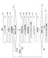
図8に,本発明において,時間に比例した時間ずれ比例係数を遠隔会議システムの立ち上げ時に学習する場合の遠隔会議システムの動作フローチャートを示す。A/D変換機104及びD/A変換機106はサンプリングをまず開始する(801)。次に,中央演算装置102は、前述した時間領域もしくは,時間周波数領域におけるフィルタ学習により,時間に比例した時間ずれ比例係数aを算出する(802)。算出した比例係数aはフィルタDBに格納される。時間に比例した時間ずれ比例係数aの算出にあたってD/A変換機から音を出す必要があるが,これは必ずしも遠隔地の音である必要はなく,遠隔会議システム内に予め用意してある音を再生するような構成をとっても良い。そして,遠隔地と接続し遠隔会議を開始する(803)。802において音響処理301のフィルタ学習部505が時間に比例した時間ずれ比例係数aを算出すると、遠隔会議制御処理302は、遠隔会議開始制御を開始する。
遠隔会議中は,遠隔地から送られてきたスピーカ再生用信号d(t)(参照信号)を受信(804),及び、マイクロホン入力信号x(t)を受信(805)するたびに,音響処理301の音響エコーキャンセラ部507は、まず、受信した参照信号d(t)を予めステップ802で算出した時間に比例した時間ずれ係数aを用いてd(t-at)のように補正する(806)。参照信号d(t)の補正は,sync関数を波形に重畳したり,サンプリングレート変換など,当業者であれば,よく知られた方法により行う。補正後の参照信号をdd(t)=d(t-at)と記載する。また,時間周波数領域における音響エコーキャンセラ用フィルタを用いる場合は,dd(t)を時間周波数領域信号dd(f,τ)に変換する。
次に,フィルタ学習部505は、参照信号としてdの代わりにddを用いて,LMSやRLSなどの方法で,逐次音響エコーキャンセラフィルタhを更新する。音響エコーキャンセラフィルタhの更新は,時間領域かまたは時間周波数領域で行う(807)。
次に,音響エコーキャンセラ部507は、求めたフィルタhを参照信号dd(t)に重畳し,音響エコーレプリカを作成し,作成した音響エコーレプリカをマイクロホン入力信号x(t)から引き算することにより,音響エコー成分が除去された信号を得る。時間周波数領域における音響エコーキャンセラの場合は、逆フーリエ変換508において、逆フーリエ変換により時間領域のエコー成分除去後の信号を得る(808)。
そして,音声送信部508は、音響エコー成分除去後の信号をHUBを介して,接続先に送信する(809)。ユーザーインターフェースを介したユーザー制御により遠隔会議システムが終了される場合は,遠隔会議制御処理302は、処理を終了し,それ以外の場合は,参照信号受信(804)に戻る。
図9は,遠隔会議システムで用いるマイクロホンまたはスピーカが切り替わる場合に,接続構成毎の時間に比例した時間ずれ係数を再設定するように,本発明を使用する際のフローチャートである。
A/D変換機104及びD/A変換機106はサンプリングをまず開始する(901)。次に,フィルタ学習部505は、前述した時間領域もしくは,時間周波数領域におけるフィルタ学習により,時間に比例した時間ずれ係数aを算出する(902)。このaは,初期値として用いる。そして,遠隔地と接続し遠隔会議を開始する(903)。次に,フィルタ学習部505は、A/D変換機104及びD/A変換機106の接続が変化したかどうかを判定する。変化している場合は,aの再設定(905)に移る。
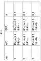
ここで,接続されているA/D変換機104、D/A変換機106及びそれらのサンプリングレート毎にそれに対応した時間に比例した時間ずれ比例係数aをフィルタDB上に,図10に示すようなデータ構造で,有しておくものとする。
ここで,切り替わった後のA/D変換機とD/A変換機の構成が図10のテーブル上に存在する場合,フィルタ学習部505は、図10のテーブルを参照し,接続されているA/D変換機104及びD/A変換機106及びそれらのサンプリングレートに対応する時間に比例した時間ずれ比例係数aを新しい時間に比例した時間ずれ比例係数aとして用いる。図10のテーブル上に対応するA/D変換機、D/A変換機、及びそれらのサンプリングレートが無い場合は,フィルタ学習部505は、前述した時間領域もしくは時間周波数領域におけるフィルタ学習によりaを求める。A/D変換機とD/A変換機の接続関係が変化していない場合は,通常の遠隔会議の音声通信状態に移る。
遠隔会議中は,遠隔地から送られてきたスピーカ再生用信号(参照信号)の受信と(906),マイク入力信号の取得(907)を行うたびに,音響エコーキャンセラ部は、まず参照信号補正(908)にて、得られた参照信号を予め算出した時間に比例した時間ずれ係数aを用いてd(t-at)のように補正する。補正は,sync関数を波形に重畳したり,サンプリングレート変換など,当業者であれば,よく知られた方法により行う。補正後の信号をdd(t)=d(t-at)と記載する。また,時間周波数領域における音響エコーキャンセラ用フィルタを用いる場合は,dd(t)を時間周波数領域信号dd(f,τ)に変換する。
次に,フィルタ学習部は、参照信号としてdの代わりにddを用いて,LMSやRLSなどの方法で,逐次音響エコーキャンセラフィルタhを更新する。更新は,時間領域かまたは時間周波数領域で行う(909)。次に音響エコーキャンセラ部は、求めたフィルタhを参照信号に重畳し,音響エコーレプリカを作成し,作成した音響エコーレプリカをマイク入力信号から引き算することにより,音響エコー成分が除去された信号を得る。時間周波数領域における音響エコーキャンセラの場合は逆フーリエ変換により時間領域の音響エコー成分除去後の信号を得る(910)。
そして,音声送信部509は、音響エコー成分除去後の信号をHUBを介して,接続先に送信する(911)。ユーザーインターフェースを介したユーザー制御により遠隔会議システムが終了される場合は,処理を終了し,それ以外の場合は,接続切り替え判定(804)に戻る。
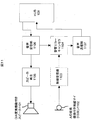
図11に,D/A変換機付きのスピーカとA/D変換機つきのマイクロホンを用いた遠隔会議システムの実施例を示す。D/A変換機能が内在されたD/A変換機能付きスピーカ1101と,A/D変換機能付き無線マイクロホン1102には,アナログ信号ではなく,デジタル信号が入力もしくは出力される。したがってこれらは異なるクロックでサンプリングされることとなる。
音声受信部1106は,接続先の遠隔会議システムから送信された音声信号をHUB108経由で受け取る。受け取った音声信号は,スピーカ再生1105により,D/A変換機能が内在されたD/A変換機能付きスピーカ1101に送られて再生される。無線受信機1103は,A/D変換機能付き無線マイクロホン1102で収録したマイク入力信号を受信する。音響エコーキャンセラ1104は,マイク入力信号中に含まれる,D/A変換機能が内在されたD/A変換機能付きスピーカ1101から再生した音声の音響エコー成分を除去する。除去は,本発明の第一の実施例で示した構成により,時間に比例した時間ずれを補正すると共に行う。音声送信部1107は,音響エコーキャンセラ後の信号をHUB108経由で遠隔地に送信する。音響エコーキャンセラ1104は,音響処理301と同様の処理を行うものとする。
100…拠点毎会議システム、101…不揮発性メモリ、102…中央演算装置、103…揮発性メモリ、104…A/D変換機、105…マイクロホン、106…D/A変換機、107…スピーカ、108…HUB、109…カメラ、110…ディスプレイ、110…ユーザーインターフェース、201…MCU、301…音響処理、302…遠隔会議制御処理、501…音声取り込み部、502…音声受信部、503…バッファリング、504…短時間フーリエ変換、505…フィルタ学習部、506…フィルタDB、507…音響エコーキャンセラ、508…短時間フーリエ変換、509…音声送信部、1101…D/A変換機能付きスピーカ、1102…A/D変換機能付き無線マイクロホン、1103…無線受信機、 1104…音響エコーキャンセラ、 1105…スピーカ再生、1106…音声受信部、1107…音声送信部
Claims (12)
- 音声を入力するマイクロホンと、
前記マイクロホンからの信号をデジタル変換するAD変換器と、
前記AD変換器からのデジタル信号を処理し音響エコー成分を抑圧する情報処理装置と、
前記情報処理装置からの信号をネットワークに送出する出力インターフェースと、
前記ネットワークからの信号を受信する入力インターフェースと、
前記入力インターフェースからの信号をアナログ変換するDA変換器と、
前記DA変換器からの信号を音声として出力するスピーカと、備えた音声システムであって、
前記情報処理装置は、
前記A/D変換機と前記D/A変換機との間の時間に比例した時間ずれ係数を推定するフィルタ学習部と、
前記推定した時間に比例した時間ずれ係数を用いて、前記AD変換器で得られたデジタル音声波形から音響エコー成分を除去する音響エコーキャンセラ部と、を備えることを特徴とする音声システム。 - 前記フィルタ学習部は、
前記ネットワークから入力されるデジタル音声波形と、前記AD変換器で得られたデジタル音声波形と、に基づいて前記時間に比例した時間ずれ係数を推定することを特徴とする請求項1に記載の音声システム。 - 前記音響エコーキャンセラ部は、前記ネットワークから入力されるデジタル音声波形を前記推定した時間に比例した時間ずれ係数を用いて補正し、
前記フィルタ学習部は、補正したデジタル音声波形を用いて音響エコーキャンセラフィルタを更新し、
前記音響エコーキャンセラ部は、更新した音響エコーキャンセラフィルタを前記補正したデジタル音声波形に重畳して音響エコーレプリカを作成し,作成した前記音響エコーレプリカを前記AD変換器で得られたデジタル音声波形から引き算することで音響エコー成分を除去することを特徴とする請求項2に記載の音声システム。 - 前記情報処理装置は、
A/D変換機を識別する識別子、D/A変換機を識別する識別子、該A/D変換機のサンプリングレート、及び、該D/A変換機のサンプリングレートの組み合わせに対応した時間に比例した時間ずれ係数を保持するデータベースを備え、
接続されるA/D変換機またはD/A変換機が変更されたことを検出すると、前記データベースを参照して、接続されるA/D変換機、D/A変換機、及び、該A/D変換機と該D/A変換機のサンプリングレートに対応する時間に比例した時間ずれ係数を取得し、取得した時間に比例した時間ずれ係数を用いて前記AD変換器で得られたデジタル音声波形から音響エコー成分を除去することを特徴とする請求項3に記載の音声システム。 - 音響エコー成分を除去する方法であって、
マイクロホンで音声を受信するステップと、
前記マイクロホンからの信号をAD変換器でデジタル変換するステップと、
ネットワークからの信号を受信するステップと、
前記ネットワークから受信した信号をDA変換器でアナログ変換するステップと、
前記DA変換器からの信号を音声としてスピーカから出力するステップと、
前記A/D変換機と前記D/A変換機との間の時間に比例した時間ずれ係数を推定するステップと、
前記推定した時間に比例した時間ずれ係数を用いて、前記AD変換器で得られたデジタル音声波形から音響エコー成分を除去するステップと、
前記音響エコー成分を抑圧したデジタル信号をネットワークに送出するステップと、を含む音響エコー成分を除去する方法。 - 前記A/D変換機と前記D/A変換機との間の時間に比例した時間ずれ係数を推定するステップは。
前記ネットワークから入力されるデジタル音声波形と、前記AD変換器で得られたデジタル音声波形と、に基づいて前記時間に比例した時間ずれ係数を推定することを特徴とする請求項5に記載の音響エコー成分を除去する方法。 - 前記ネットワークから入力されるデジタル音声波形を前記推定した時間に比例した時間ずれ係数を用いて補正するステップと、
前記補正したデジタル音声波形を用いて音響エコーキャンセラフィルタを更新するステップと、
前記更新した音響エコーキャンセラフィルタを前記補正したデジタル音声波形に重畳して音響エコーレプリカを作成し,作成した前記音響エコーレプリカを前記AD変換器で得られたデジタル音声波形から引き算することで音響エコー成分を除去するステップと、を含むことを特徴とする請求項6に記載の音響エコー成分を除去する方法。 - A/D変換機を識別する識別子、D/A変換機を識別する識別子、該A/D変換機のサンプリングレート、及び、該D/A変換機のサンプリングレートの組み合わせに対応した時間に比例した時間ずれ係数を保持するデータベースを備え、
接続されるA/D変換機またはD/A変換機が変更されたことを検出するステップと、
前記データベースを参照して、接続されるA/D変換機、D/A変換機、及び、該A/D変換機と該D/A変換機のサンプリングレートに対応する時間に比例した時間ずれ係数を取得するステップと、
取得した時間に比例した時間ずれ係数を用いて前記AD変換器で得られたデジタル音声波形から音響エコー成分を除去するステップと、を含むことを特徴とする請求項7に記載の音響エコー成分を除去する方法。 - マイクロホンからの音声信号をAD変換器でデジタル変換したデジタル音声波形を取り込む音声取り込み部と、
DA変換器で変換してスピーカで再生するためのスピーカ再生用のデジタル音声信号を受信する音声受信部と、
前記A/D変換機と前記D/A変換機との間の時間に比例した時間ずれ係数を推定するフィルタ学習部と、
前記推定した時間に比例した時間ずれ係数を用いて、前記AD変換器で得られたデジタル音声波形から音響エコー成分を除去する音響エコーキャンセラ部と、
前記AD変換器で得られたデジタル音声波形から音響エコー成分を除去したデジタル音声波形を出力する音声送信部と、を備えることを特徴とする音響エコーキャンセラ。 - 前記フィルタ学習部は、
前記音声受信部で受信するデジタル音声波形と、前記AD変換器で得られたデジタル音声波形と、に基づいて前記時間に比例した時間ずれ係数を推定することを特徴とする請求項9に記載の音響エコーキャンセラ。 - 前記音響エコーキャンセラ部は、前記音声受信部で受信するデジタル音声波形を前記推定した時間に比例した時間ずれ係数を用いて補正し、
前記フィルタ学習部は、補正したデジタル音声波形を用いて音響エコーキャンセラフィルタを更新し、
前記音響エコーキャンセラ部は、更新した音響エコーキャンセラフィルタを前記補正したデジタル音声波形に重畳して音響エコーレプリカを作成し,作成した前記音響エコーレプリカを前記AD変換器で得られたデジタル音声波形から引き算することで音響エコー成分を除去することを特徴とする請求項10に記載の音響エコーキャンセラ。 - A/D変換機を識別する識別子、D/A変換機を識別する識別子、該A/D変換機のサンプリングレート、及び、該D/A変換機のサンプリングレートの組み合わせに対応した時間に比例した時間ずれ係数を保持するデータベースを備え、
接続されるA/D変換機またはD/A変換機が変更されたことを検出すると、前記データベースを参照して、接続されるA/D変換機、D/A変換機、及び、該A/D変換機と該D/A変換機のサンプリングレートに対応する時間に比例した時間ずれ係数を取得し、取得した時間に比例した時間ずれ係数を用いて前記AD変換器で得られたデジタル音声波形から音響エコー成分を除去することを特徴とする請求項11に記載の音響エコーキャンセラ。
Priority Applications (2)
| Application Number | Priority Date | Filing Date | Title |
|---|---|---|---|
| PCT/JP2013/051520 WO2014115290A1 (ja) | 2013-01-25 | 2013-01-25 | 信号処理装置・音響処理システム |
| JP2014558373A JPWO2014115290A1 (ja) | 2013-01-25 | 2013-01-25 | 信号処理装置・音響処理システム |
Applications Claiming Priority (1)
| Application Number | Priority Date | Filing Date | Title |
|---|---|---|---|
| PCT/JP2013/051520 WO2014115290A1 (ja) | 2013-01-25 | 2013-01-25 | 信号処理装置・音響処理システム |
Publications (1)
| Publication Number | Publication Date |
|---|---|
| WO2014115290A1 true WO2014115290A1 (ja) | 2014-07-31 |
Family
ID=51227105
Family Applications (1)
| Application Number | Title | Priority Date | Filing Date |
|---|---|---|---|
| PCT/JP2013/051520 Ceased WO2014115290A1 (ja) | 2013-01-25 | 2013-01-25 | 信号処理装置・音響処理システム |
Country Status (2)
| Country | Link |
|---|---|
| JP (1) | JPWO2014115290A1 (ja) |
| WO (1) | WO2014115290A1 (ja) |
Cited By (5)
| Publication number | Priority date | Publication date | Assignee | Title |
|---|---|---|---|---|
| JP2014533014A (ja) * | 2012-07-06 | 2014-12-08 | ゴーアーテック インク | 送受話端サンプリングレート偏差の補正方法及びシステム |
| KR101842777B1 (ko) * | 2016-07-26 | 2018-03-27 | 라인 가부시키가이샤 | 음질 개선 방법 및 시스템 |
| CN109817235A (zh) * | 2018-12-12 | 2019-05-28 | 深圳市潮流网络技术有限公司 | 一种VoIP设备的回声消除方法 |
| CN112055284A (zh) * | 2019-06-05 | 2020-12-08 | 北京地平线机器人技术研发有限公司 | 回声消除方法及神经网络的训练方法、装置、介质、设备 |
| CN115273877A (zh) * | 2021-04-29 | 2022-11-01 | 海信集团控股股份有限公司 | 智能传感器、回音消除方法、服务设备和回音消除系统 |
Citations (2)
| Publication number | Priority date | Publication date | Assignee | Title |
|---|---|---|---|---|
| JP2010056778A (ja) * | 2008-08-27 | 2010-03-11 | Nippon Telegr & Teleph Corp <Ntt> | エコー消去装置、エコー消去方法、エコー消去プログラム、記録媒体 |
| JP2011080868A (ja) * | 2009-10-07 | 2011-04-21 | Hitachi Ltd | 音響監視システム、及び音声集音システム |
Family Cites Families (1)
| Publication number | Priority date | Publication date | Assignee | Title |
|---|---|---|---|---|
| JP2007214976A (ja) * | 2006-02-10 | 2007-08-23 | Sharp Corp | エコーキャンセル装置、テレビ電話端末、及びエコーキャンセル方法 |
-
2013
- 2013-01-25 WO PCT/JP2013/051520 patent/WO2014115290A1/ja not_active Ceased
- 2013-01-25 JP JP2014558373A patent/JPWO2014115290A1/ja active Pending
Patent Citations (2)
| Publication number | Priority date | Publication date | Assignee | Title |
|---|---|---|---|---|
| JP2010056778A (ja) * | 2008-08-27 | 2010-03-11 | Nippon Telegr & Teleph Corp <Ntt> | エコー消去装置、エコー消去方法、エコー消去プログラム、記録媒体 |
| JP2011080868A (ja) * | 2009-10-07 | 2011-04-21 | Hitachi Ltd | 音響監視システム、及び音声集音システム |
Cited By (8)
| Publication number | Priority date | Publication date | Assignee | Title |
|---|---|---|---|---|
| JP2014533014A (ja) * | 2012-07-06 | 2014-12-08 | ゴーアーテック インク | 送受話端サンプリングレート偏差の補正方法及びシステム |
| KR101842777B1 (ko) * | 2016-07-26 | 2018-03-27 | 라인 가부시키가이샤 | 음질 개선 방법 및 시스템 |
| US10136235B2 (en) | 2016-07-26 | 2018-11-20 | Line Corporation | Method and system for audio quality enhancement |
| CN109817235A (zh) * | 2018-12-12 | 2019-05-28 | 深圳市潮流网络技术有限公司 | 一种VoIP设备的回声消除方法 |
| CN109817235B (zh) * | 2018-12-12 | 2024-05-24 | 深圳市潮流网络技术有限公司 | 一种VoIP设备的回声消除方法 |
| CN112055284A (zh) * | 2019-06-05 | 2020-12-08 | 北京地平线机器人技术研发有限公司 | 回声消除方法及神经网络的训练方法、装置、介质、设备 |
| CN112055284B (zh) * | 2019-06-05 | 2022-03-29 | 北京地平线机器人技术研发有限公司 | 回声消除方法及神经网络的训练方法、装置、介质、设备 |
| CN115273877A (zh) * | 2021-04-29 | 2022-11-01 | 海信集团控股股份有限公司 | 智能传感器、回音消除方法、服务设备和回音消除系统 |
Also Published As
| Publication number | Publication date |
|---|---|
| JPWO2014115290A1 (ja) | 2017-01-26 |
Similar Documents
| Publication | Publication Date | Title |
|---|---|---|
| CN102044253B (zh) | 一种回声信号处理方法、系统及电视机 | |
| KR101017384B1 (ko) | 잡음제거시스템, 음성취득장치, 음성출력장치 및프로그램을 기록한 컴퓨터 판독 가능한 기록매체 | |
| JP5897343B2 (ja) | 残響除去パラメータ推定装置及び方法、残響・エコー除去パラメータ推定装置、残響除去装置、残響・エコー除去装置、並びに、残響除去装置オンライン会議システム | |
| US9591123B2 (en) | Echo cancellation | |
| EP2652737B1 (en) | Noise reduction system with remote noise detector | |
| US8842851B2 (en) | Audio source localization system and method | |
| CN102461205B (zh) | 多通道声学回声消除器装置和多通道声学回声消除的方法 | |
| US20080304653A1 (en) | Acoustic echo cancellation solution for video conferencing | |
| US9966086B1 (en) | Signal rate synchronization for remote acoustic echo cancellation | |
| WO2014115290A1 (ja) | 信号処理装置・音響処理システム | |
| KR101445186B1 (ko) | 비선형 보정 반향 제거장치 | |
| WO2016096339A1 (en) | Delay estimation for echo cancellation using ultrasonic markers | |
| US8718562B2 (en) | Processing audio signals | |
| JP4725422B2 (ja) | エコーキャンセル回路、音響装置、ネットワークカメラ、及びエコーキャンセル方法 | |
| JP6903884B2 (ja) | 信号処理装置、プログラム及び方法、並びに、通話装置 | |
| KR102194165B1 (ko) | 에코 제거기 | |
| JP2015521421A (ja) | 長く遅延したエコーのためのエコーキャンセレーションアルゴリズム | |
| CN113424558A (zh) | 智能个人助理 | |
| JP2014200056A (ja) | 携帯端末、プログラム、通話システム | |
| CN113938548A (zh) | 一种终端通信的回声抑制方法和装置 | |
| JP5167706B2 (ja) | 放収音装置 | |
| JP2004128825A (ja) | エコーキャンセラ装置及びそれに用いるエコーキャンセラ方法 | |
| JP4743085B2 (ja) | エコーキャンセラ | |
| JP4622713B2 (ja) | エコーキャンセラを備える拡声集音通信装置 | |
| JP2006270877A (ja) | 集合住宅用インターホンシステム |
Legal Events
| Date | Code | Title | Description |
|---|---|---|---|
| 121 | Ep: the epo has been informed by wipo that ep was designated in this application |
Ref document number: 13873086 Country of ref document: EP Kind code of ref document: A1 |
|
| ENP | Entry into the national phase |
Ref document number: 2014558373 Country of ref document: JP Kind code of ref document: A |
|
| NENP | Non-entry into the national phase |
Ref country code: DE |
|
| 122 | Ep: pct application non-entry in european phase |
Ref document number: 13873086 Country of ref document: EP Kind code of ref document: A1 |