WO2014109278A1 - Bogie for rolling stock and rolling stock provided therewith - Google Patents
Bogie for rolling stock and rolling stock provided therewith Download PDFInfo
- Publication number
- WO2014109278A1 WO2014109278A1 PCT/JP2014/000004 JP2014000004W WO2014109278A1 WO 2014109278 A1 WO2014109278 A1 WO 2014109278A1 JP 2014000004 W JP2014000004 W JP 2014000004W WO 2014109278 A1 WO2014109278 A1 WO 2014109278A1
- Authority
- WO
- WIPO (PCT)
- Prior art keywords
- leaf spring
- axle box
- bogie
- vehicle
- stopper
- Prior art date
Links
Images


Classifications
-
- B—PERFORMING OPERATIONS; TRANSPORTING
- B61—RAILWAYS
- B61F—RAIL VEHICLE SUSPENSIONS, e.g. UNDERFRAMES, BOGIES OR ARRANGEMENTS OF WHEEL AXLES; RAIL VEHICLES FOR USE ON TRACKS OF DIFFERENT WIDTH; PREVENTING DERAILING OF RAIL VEHICLES; WHEEL GUARDS, OBSTRUCTION REMOVERS OR THE LIKE FOR RAIL VEHICLES
- B61F5/00—Constructional details of bogies; Connections between bogies and vehicle underframes; Arrangements or devices for adjusting or allowing self-adjustment of wheel axles or bogies when rounding curves
- B61F5/26—Mounting or securing axle-boxes in vehicle or bogie underframes
-
- B—PERFORMING OPERATIONS; TRANSPORTING
- B61—RAILWAYS
- B61F—RAIL VEHICLE SUSPENSIONS, e.g. UNDERFRAMES, BOGIES OR ARRANGEMENTS OF WHEEL AXLES; RAIL VEHICLES FOR USE ON TRACKS OF DIFFERENT WIDTH; PREVENTING DERAILING OF RAIL VEHICLES; WHEEL GUARDS, OBSTRUCTION REMOVERS OR THE LIKE FOR RAIL VEHICLES
- B61F5/00—Constructional details of bogies; Connections between bogies and vehicle underframes; Arrangements or devices for adjusting or allowing self-adjustment of wheel axles or bogies when rounding curves
- B61F5/50—Other details
- B61F5/52—Bogie frames
-
- B—PERFORMING OPERATIONS; TRANSPORTING
- B61—RAILWAYS
- B61F—RAIL VEHICLE SUSPENSIONS, e.g. UNDERFRAMES, BOGIES OR ARRANGEMENTS OF WHEEL AXLES; RAIL VEHICLES FOR USE ON TRACKS OF DIFFERENT WIDTH; PREVENTING DERAILING OF RAIL VEHICLES; WHEEL GUARDS, OBSTRUCTION REMOVERS OR THE LIKE FOR RAIL VEHICLES
- B61F5/00—Constructional details of bogies; Connections between bogies and vehicle underframes; Arrangements or devices for adjusting or allowing self-adjustment of wheel axles or bogies when rounding curves
- B61F5/26—Mounting or securing axle-boxes in vehicle or bogie underframes
- B61F5/30—Axle-boxes mounted for movement under spring control in vehicle or bogie underframes
- B61F5/301—Axle-boxes mounted for movement under spring control in vehicle or bogie underframes incorporating metal springs
- B61F5/302—Leaf springs
-
- B—PERFORMING OPERATIONS; TRANSPORTING
- B61—RAILWAYS
- B61F—RAIL VEHICLE SUSPENSIONS, e.g. UNDERFRAMES, BOGIES OR ARRANGEMENTS OF WHEEL AXLES; RAIL VEHICLES FOR USE ON TRACKS OF DIFFERENT WIDTH; PREVENTING DERAILING OF RAIL VEHICLES; WHEEL GUARDS, OBSTRUCTION REMOVERS OR THE LIKE FOR RAIL VEHICLES
- B61F5/00—Constructional details of bogies; Connections between bogies and vehicle underframes; Arrangements or devices for adjusting or allowing self-adjustment of wheel axles or bogies when rounding curves
- B61F5/26—Mounting or securing axle-boxes in vehicle or bogie underframes
- B61F5/30—Axle-boxes mounted for movement under spring control in vehicle or bogie underframes
- B61F5/305—Axle-boxes mounted for movement under spring control in vehicle or bogie underframes incorporating rubber springs
Definitions
- the present invention relates to a carriage that supports the body of a railway vehicle, and more particularly to a railway vehicle carriage that prevents the leaf springs from falling off.
- a bogie of a railway vehicle is composed of wheels, an axle, and a bogie frame, and the bogie frame is a pair of sides extending in the front-rear direction joined by welding or the like to a lateral beam extending in the vehicle width direction and both ends of the horizontal beam.
- the axle box in which the bearing which supports an axle shaft is accommodated is supported by the axle box support device, and is configured to be vertically displaceable with respect to the carriage frame.
- Patent Document 1 proposes a cart that omits the side flash.
- the bogie described in Patent Document 1 uses a primary suspension as a leaf spring, the center portion of the leaf spring in the front-rear direction is fixed to both ends in the width direction of the lateral beam, and both end portions in the front-rear direction of the leaf spring are provided in the axle box. It is configured to be inserted into the spring receiver.
- the spring receiver described in Patent Document 1 is formed in a cylindrical shape, and it is not easy to insert a leaf spring into the spring receiver.
- plate spring it is calculated
- the present invention has been made in view of such circumstances, and is a railcar bogie provided with a leaf spring, which is easy to attach the leaf spring, and the leaf spring is less likely to fall off.
- the purpose is to provide.
- a railcar bogie includes a lateral beam that extends in the vehicle width direction to support the vehicle body, a leaf spring that extends in the vehicle longitudinal direction to support both ends in the vehicle width direction, and an axle. And a shaft box that supports the longitudinal end of the leaf spring in the vehicle longitudinal direction, and is positioned between the leaf spring and the axle box, and the upper surface is inclined toward the longitudinal center portion of the leaf spring.
- a leaf spring receiver for receiving the leaf spring on the upper surface, and a stopper disposed to cover at least a part of the upper surface of the leaf spring in the vicinity of the longitudinal end of the leaf spring in the vehicle longitudinal direction above the axle box And.
- the leaf spring can be attached simply by placing each member on the upper surface of the axle box in order, and since the stopper is provided, the leaf spring can be prevented from falling off.
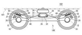
- FIG. 1 is a side view of a carriage according to the first embodiment.
- FIG. 2 is a plan view of the carriage shown in FIG.
- FIG. 3 is an enlarged side view of the upper portion of the axle box in the cart shown in FIG.
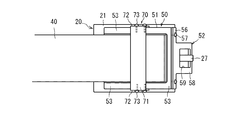
- FIG. 4 is a plan view of the portion shown in FIG.
- FIG. 5 is an exploded view of the portion shown in FIG.
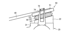
- FIG. 6 is an enlarged side view of the upper part of the axle box in the cart according to the second embodiment.
- FIG. 7 is a plan view of the portion shown in FIG.
- FIG. 1 is a side view of the carriage 100
- FIG. 2 is a plan view of the carriage 100.
- the left-right direction in FIG. 1 is the “vehicle longitudinal direction”, and the direction perpendicular to the page is the “vehicle width direction”.
- a carriage 100 is used for a railway vehicle 102, and includes a wheel 10, a shaft box 20, a side beam 30, a leaf spring 40, a leaf spring receiver 50, and a gap body. 60 and a stopper 70.
- Wheels 10 are arranged at four locations on the carriage 100. As shown in FIG. 2, the wheels 10 facing each other in the vehicle width direction are connected by an axle 11, and the axle 11 is held by a bearing 12 on the outer side in the vehicle width direction than the wheels 10.
- the cart 100 according to the present embodiment is a so-called accompanying cart and does not include a drive device. However, in the case of an electric cart, the axle 11 is connected to an electric motor via a gear box, and the axle 11 is driven by the electric motor. Is done.
- the axle box 20 is a member that accommodates the bearing 12 and is a part that supports the leaf spring 40 via a leaf spring receiver 50 and a gap body 60 described later.
- 3 is an enlarged side view of the upper portion of the axle box 20
- FIG. 4 is a plan view of the portion shown in FIG. 3
- FIG. 5 is an exploded view of the portion shown in FIG.
- the axle box 20 has an axle box body 21 and a spring seat 22 placed on the axle box body 21.
- the support surface 23 corresponding to the upper surface of the spring seat 22 is inclined toward the center in the longitudinal direction of the leaf spring 40, and a columnar insertion piece 24 is formed at the center.
- An insertion hole 25 is formed on the lower surface of the spring seat 22, and an insertion piece 26 is formed on the upper surface of the axle box body 21.
- the axle box 20 has a locking portion 27.
- the locking portion 27 is located on the outer side in the vehicle longitudinal direction of the axle box body 21 and is formed to extend toward the outer side in the vehicle longitudinal direction.
- the locking part 27 is formed so as to penetrate a locking hole 59 (see FIG. 4) formed in the locked part 52 of the leaf spring receiver 50 described later.
- locking part 27 is not specifically limited, as shown in FIG. 5, in this embodiment, it forms so that the lower surface of the part close
- the position of the locking portion 27 is not particularly limited, and the locking portion 27 may be attached to the side surface of the axle box body 21 in the vehicle width direction. In short, any configuration may be employed as long as the locked portion 52 is locked to the locking portion 27 when the locked portion 52 is about to move upward.
- the side cover 30 is a member that supports the vehicle body 101.
- the side beam 30 is composed of a pair of metal square pipes 31 extending in the vehicle width direction, and a connecting member that is located near both ends of the square pipe 31 in the vehicle width direction and connects the two square pipes 31. 32.
- the connection member 32 holds an air spring pedestal 33 on its upper surface, and an air spring 34 serving as a secondary suspension is attached to the air spring pedestal 33. That is, the horizontal beam 30 supports the vehicle body 101 via the air spring 34 and the air spring pedestal 33.
- the leaf spring 40 is a member having a function of a conventional coil spring (primary suspension) and a side beam.
- the leaf spring 40 extends in the longitudinal direction of the vehicle, and supports both end portions in the vehicle width direction of the lateral beam 30 via the contact member 35 at the center portion thereof. Further, both end portions of the leaf spring 40 in the longitudinal direction are supported by the axle box 20 via leaf spring receivers 50 and the like.
- the leaf spring 40 is formed in a bow shape that protrudes downward in a side view. Therefore, both ends of the plate spring 40 in the longitudinal direction of the vehicle are in a state where a force in the direction toward the central portion in the longitudinal direction is always applied.
- plate spring 40 is not specifically limited,
- the composite material which consists of the lower layer part formed with the fiber reinforced resin and the upper layer part formed with the thin metal can be used.
- the central portion in the longitudinal direction of the leaf spring 40 is formed so as to be thicker than both end portions in the longitudinal direction.
- the leaf spring receiver 50 is a member that is positioned at both ends in the longitudinal direction of the leaf spring 40 and receives the leaf spring 40 on the upper surface.
- the leaf spring receiver 50 includes a leaf spring receiving body 51 and a locked portion 52 attached to the leaf spring receiving body 51.
- the leaf spring receiving body 51 has a substantially rectangular shape in plan view, and includes an inner side in the vehicle width direction, an outer side in the vehicle width direction, and an outer side in the vehicle longitudinal direction. Protective walls 53 are formed on these three sides.
- a rubber sheet 54 is laid on a portion surrounded by the protective wall 53 in the plate spring receiving body 51, and the plate spring receiver 50 receives the plate spring 40 by this rubber sheet 54. ing.
- the upper surface of the plate spring receiver 50 that receives the plate spring 40 is inclined toward the longitudinal center portion of the plate spring 40.
- a cylindrical insertion piece 55 is formed on the lower surface of the leaf spring receiving body 51.
- the locked portion 52 is a portion that is locked to the locking portion 27 of the axle box 20 described above.
- the locked portion 52 of the present embodiment is a plate-like member formed in a substantially T shape, and the mounting portion 56 corresponding to the upper portion is the vehicle longitudinal direction outer side of the leaf spring receiving body 51. It is fixed to the surface with a screw 57.
- the extended portion 58 located below the attachment portion 56 in the locked portion 52 extends to the axle box 20.
- a locking hole 59 is formed in the extending portion 58, and the locking portion 27 of the axle box 20 is inserted into the locking hole 59. That is, the locking portion 27 passes through the locking hole 59.
- the to-be-latched part 52 is not restricted to the substantially T-shaped shape mentioned above,
- the attaching part 56 may extend to the vehicle width direction both sides
- the leaf spring receiving body 51 and the locked portion 52 may be integrally formed.
- the gap body 60 is a member disposed between the leaf spring receiver 50 and the axle box 20. As shown in FIG. 5, the gap body 60 is mainly configured by two elastic plates 61 and a rubber seat 62 disposed between the two elastic plates 61.
- the elastic plate 61 and the rubber seat 62 are both formed in an annular shape.
- the upper elastic plate 61 of the two elastic plates 61 is formed by laminating a first metal plate 63, a rubber layer 64, and a second metal plate 65 in order from the top.
- the lower elastic plate 61 is formed by laminating a second metal plate 65, a rubber layer 64, and a first metal plate 63 in order from the top.
- the rubber seat 62 has annular grooves 66 formed on both sides thereof, and the second metal plate 65 is fitted in the annular grooves 66.
- the stopper 70 is a member for preventing the leaf spring 40 from falling off, and covers at least a part of the upper surface of the leaf spring 40 in the vicinity of the longitudinal end portion of the leaf spring 40 above the axle box 20.
- the stopper 70 of the present embodiment includes an upper surface portion 71 positioned above the plate spring 40 and side surface portions 72 that are positioned at both ends of the upper surface portion 71 in the vehicle width direction and are fixed to the side surfaces of the plate spring receiver 50. Have. Specifically, each side surface 72 is fixed to the side surface in the vehicle width direction of the leaf spring receiver 50 by a screw 73.
- the upper surface portion 71 is configured to cover the entire vehicle width direction of the leaf spring 40, but the upper surface portion 71 may be configured to cover a portion of the leaf spring 40 in the vehicle width direction.
- the stopper 70 may be formed in an L shape and fixed to both side surfaces of the leaf spring receiver 50 in the vehicle width direction.
- the stopper 70 and the leaf spring receiver 50 may be integrally formed without being configured so that the stopper 70 can be detached from the leaf spring receiver 50.
- the insertion piece 26 of the axle box body 21 is inserted into the insertion hole 25 of the spring seat 22, and the spring seat 22 is attached to the upper surface of the axle box body 21.
- the insertion piece 24 of the spring seat 22 is inserted into the inner peripheral portion of the first metal plate 63 of the lower elastic plate 61, the rubber seat 62 is overlaid on the upper surface, and another elastic plate 61 is further placed thereon. Overlapping. Accordingly, the gap body 60 can be attached to the upper surface of the spring seat 22.
- the insertion piece 55 of the plate spring support body 51 is inserted into the inner peripheral portion of the first metal plate 63 of the upper elastic plate 61, and the plate spring support body 51 is attached to the upper surface of the gap body 60.
- the leaf spring 40 is placed on the upper surface of the leaf spring receiving body 51.
- the locked portion 52 and the stopper 70 are fixed to the leaf spring receiving body 51.
- the leaf spring 40 can be attached by simply stacking the respective members in order, so that the attachment work of the leaf spring 40 is very easy.
- the leaf spring 40 since the leaf spring 40 has an arcuate shape, the leaf spring 40 is stable in a state where a force in a direction in which both end portions in the longitudinal direction are directed toward the center portion in the longitudinal direction is applied. Yes. Therefore, the longitudinal end portions of the leaf spring 40 are not easily displaced in the direction toward the longitudinal center portion. Then, since the upper surface of the leaf spring receiver 50 is inclined toward the longitudinal center portion of the leaf spring 40 along the shape of the leaf spring 40, it can be said that the leaf spring 40 is not easily displaced on the upper surface of the leaf spring receiver 50. Therefore, in this embodiment, although the leaf spring 40 is merely attached by overlapping each member, the leaf spring 40 does not fall off in a normal operation state.
- the leaf spring 40 is lifted when an impact much larger than the impact received in normal operation, such as the derailment of the railway vehicle 102, is applied to the leaf spring 40. If the leaf spring 40 is lifted, the leaf spring 40 is caught by the stopper 70 and the leaf spring receiver 50 is also lifted, but the locked portion 52 of the leaf spring receiver 50 is engaged with the shaft box 20. Locked by the stop 27, the plate spring receiver 50 is prevented from floating. As a result, the upward movement of the leaf spring 40 with respect to the axle box 20 is restricted, and the leaf spring 40 can be prevented from falling off the leaf spring receiver 50 and the leaf spring receiver 50 from falling off the axle box 20.
- FIG. 6 is an enlarged side view of the upper portion of the axle box 20 of the cart 200 according to the present embodiment
- FIG. 7 is a plan view of the portion shown in FIG.
- the stopper 70 is fixed to the leaf spring receiver 50, whereas in the cart 200 according to the present embodiment, the two stoppers 70 are stoppers. They are different in that they are held by the holding unit 74.
- the axle box 20 does not have the locking portion 27, and the leaf spring receiver 50 does not have the locked portion 52.
- the stopper holding portions 74 are located on both sides of the leaf spring 40 in the vehicle width direction, and the lower end portions thereof are fixed to the axle box 20. Further, as shown in FIG. 7, holding holes 75 are formed at two positions on the upper end portion of each stopper holding portion 74.
- the stopper 70 is a metal round bar and extends in the vehicle width direction so as to pass both stopper holding portions 74. An internal thread is formed at the end of the stopper 70.
- Each stopper 70 is arranged corresponding to the holding hole 75 of the stopper holding part 74, and a screw 76 is screwed into the female screw of the stopper 70 through the holding hole 75 from the outer side in the vehicle width direction of the stopper holding part 74. . Thereby, each stopper 70 is fixed to the stopper holding portion 74. That is, each stopper 70 is held by the stopper holding portion 74.
- the cart 200 according to this embodiment is configured as described above, after laminating each member and placing the leaf spring 40 on the leaf spring receiving body 51, as in the case of the first embodiment, Finally, when the stopper 70 is attached to the stopper holding portion 74, the attaching operation of the leaf spring 40 is completed.
- the leaf spring 40 can be easily attached.
- the plate spring 40 even if the plate spring 40 is lifted, the plate spring 40 abuts against the stopper 70 and the upward movement of the plate spring 40 is restricted. Therefore, in the cart 200 according to the present embodiment, the upward movement of the leaf spring 40 and the leaf spring receiver 50 is restricted, and the leaf spring 40 is detached from the leaf spring receiver 50 and from the axle box 20 of the leaf spring receiver 50. Can be prevented from falling off.
- the bogie according to the first embodiment and the bogie according to the second embodiment have a lateral beam extending in the vehicle width direction to support the vehicle body, and both ends in the vehicle width direction of the lateral beam extending in the vehicle longitudinal direction.
- a leaf spring to be supported a shaft box that accommodates the bearing of the axle and supports the longitudinal end of the leaf spring in the vehicle longitudinal direction, and is located between the leaf spring and the axle box, toward the longitudinal central portion of the leaf spring.
- a plate spring support that receives the plate spring on the inclined upper surface, and a stopper that is disposed so as to cover the upper surface of the plate spring in the vicinity of the end of the plate spring in the vehicle longitudinal direction above the axle box. Therefore, as described above, according to such a carriage, the leaf spring can be easily attached and the leaf spring can be prevented from falling off.
- the stopper is fixed to the plate spring holder, and the plate spring holder is configured to be restricted from moving upward with respect to the axle box. Therefore, even if the leaf spring receiver is lifted by the leaf spring in contact with the stopper, the upward movement of the leaf spring receiver is restricted, and as a result, the upward movement of the leaf spring itself is restricted and the leaf spring falls off. Can be prevented.
- the axle box has an engaging portion
- the leaf spring receiver has an engaged portion that is engaged with the engaging portion
- the leaf spring receiver is attached to the axle box.
- the upward movement is limited.
- the locked portion extends from the outer side in the longitudinal direction of the plate spring support to the axle box and has a locking hole
- the locking portion extends in the outer side in the longitudinal direction of the vehicle and extends into the locking hole. It is formed so as to penetrate. Therefore, it is possible to restrict upward movement of the leaf spring support with respect to the shaft box, though the structure is simple.
- the cart according to the second embodiment further includes stopper holding portions that are positioned on both sides of the leaf spring in the vehicle width direction and are fixed to the axle box, the stoppers extend in the vehicle width direction, and both ends thereof are formed by the stopper holding portions. Is retained.
- locking part which an axial box part has can be abbreviate
- the present invention it is possible to provide a railcar bogie that can be easily attached with a leaf spring and that does not easily drop off. Therefore, the present invention is useful in the technical field of railway vehicles.
Landscapes
- Engineering & Computer Science (AREA)
- Mechanical Engineering (AREA)
- Springs (AREA)
- Vibration Prevention Devices (AREA)
Abstract
Description
まず、図1乃至図5を参照して、第1実施形態に係る台車100について説明する。図1は台車100の側面図であり、図2は台車100の平面図である。図1における紙面左右方向が「車両長手方向」であり、紙面に対して垂直な方向が「車幅方向」である。図1及び図2に示すように、台車100は鉄道車両102に用いられるものであり、車輪10と、軸箱20と、横ばり30と、板バネ40と、板バネ受50と、間隙体60と、ストッパ70と、を備えている。 (First embodiment)
First, with reference to FIG. 1 thru | or FIG. 5, the trolley |
次に、図6及び図7を参照して、第2実施形態に係る台車200について説明する。図6は、本実施形態に係る台車200のうち軸箱20上部の拡大側面図であり、図7は、図6に示す部分の平面図である。図6及び図7に示すように、第1実施形態に係る台車100ではストッパ70が板バネ受50に固定されていたのに対し、本実施形態に係る台車200では2本のストッパ70がストッパ保持部74により保持されている点で両者は相違する。なお、本実施形態に係る台車200では、軸箱20が係止部27を有しておらず、板バネ受50が被係止部52を有していない。 (Second Embodiment)
Next, with reference to FIG.6 and FIG.7, the trolley | bogie 200 which concerns on 2nd Embodiment is demonstrated. FIG. 6 is an enlarged side view of the upper portion of the
12 軸受
20 軸箱
27 係止部
30 横ばり
40 板バネ
50 板バネ受
52 被係止部
59 係止孔
70 ストッパ
74 ストッパ保持部
100、200 台車
101 車体
102 鉄道車両 DESCRIPTION OF
Claims (6)
- 車幅方向に延びて車体を支持する横ばりと、
車両長手方向に延びて前記横ばりの車幅方向両端部を支持する板バネと、
車軸の軸受を収容するとともに前記板バネの車両長手方向端部を支持する軸箱と、
前記板バネと前記軸箱の間に位置し、上面が前記板バネの長手方向中央部分に向けて傾斜し、当該上面で前記板バネを受ける板バネ受と、
前記軸箱の上方にある前記板バネの車両長手方向端部近傍において、前記板バネの上面の少なくとも一部を覆うように配置されたストッパと、
を備えた鉄道車両用台車。 A side that extends in the vehicle width direction and supports the vehicle body,
A leaf spring that extends in the longitudinal direction of the vehicle and supports both ends of the lateral width direction of the side wall;
An axle box that houses the axle bearing and supports the longitudinal end of the leaf spring in the vehicle;
A leaf spring receiver located between the leaf spring and the axle box, the upper surface of which is inclined toward the longitudinal central portion of the leaf spring, and receives the leaf spring on the upper surface;
In the vicinity of the longitudinal end of the leaf spring in the vehicle longitudinal direction above the axle box, a stopper arranged to cover at least a part of the upper surface of the leaf spring;
A railcar bogie equipped with - 前記ストッパは前記板バネ受に固定されており、
前記板バネ受は、前記軸箱に対して上方への移動が制限されるように構成されている、請求項1に記載の鉄道車両用台車。 The stopper is fixed to the leaf spring support,
The bogie for a railway vehicle according to claim 1, wherein the leaf spring support is configured to be restricted from moving upward with respect to the axle box. - 前記軸箱は係止部を有し、前記板バネ受は前記係止部に係止される被係止部を有し、
前記板バネ受が前記軸箱に対して上方への移動が制限されるように構成されている、請求項2に記載の鉄道車両用台車。 The axle box has a locking part, and the leaf spring support has a locked part locked by the locking part,
The bogie for a railway vehicle according to claim 2, wherein the leaf spring support is configured to be restricted from moving upward with respect to the axle box. - 前記被係止部は、前記板バネ受の車両長手方向外側から前記軸箱にまで延びるとともに係止孔が形成されており、
前記係止部は、車両長手方向外側に延びて前記係止孔を貫通するように形成されている、請求項3に記載の鉄道車両用台車。 The locked part extends from the outer side in the longitudinal direction of the plate spring support to the axle box and has a locking hole.
The bogie for a railway vehicle according to claim 3, wherein the locking portion is formed so as to extend outward in the vehicle longitudinal direction and penetrate the locking hole. - 前記板バネの車幅方向両側に位置し前記軸箱に固定されているストッパ保持部をさらに備え、
前記ストッパは車幅方向に延び、その両端が前記ストッパ保持部によって保持されている、請求項1に記載の鉄道車両用台車。 A stopper holding part that is positioned on both sides of the leaf spring in the vehicle width direction and is fixed to the axle box;
The carriage for a railway vehicle according to claim 1, wherein the stopper extends in a vehicle width direction, and both ends thereof are held by the stopper holding portion. - 請求項1乃至5のうちいずれか一の項に記載の鉄道車両用台車を備えた、鉄道車両。 A railway vehicle comprising the railway vehicle carriage according to any one of claims 1 to 5.
Priority Applications (4)
| Application Number | Priority Date | Filing Date | Title |
|---|---|---|---|
| US14/759,756 US9663121B2 (en) | 2013-01-10 | 2014-01-06 | Railcar bogie and railcar including same |
| KR1020157019850A KR101731504B1 (en) | 2013-01-10 | 2014-01-06 | Bogie for rolling stock and rolling stock provided therewith |
| EP14738012.5A EP2944535A4 (en) | 2013-01-10 | 2014-01-06 | Bogie for rolling stock and rolling stock provided therewith |
| CN201480003791.1A CN104870292B (en) | 2013-01-10 | 2014-01-06 | Railcar bogie and the rail truck for possessing the railcar bogie |
Applications Claiming Priority (2)
| Application Number | Priority Date | Filing Date | Title |
|---|---|---|---|
| JP2013-002706 | 2013-01-10 | ||
| JP2013002706A JP6110669B2 (en) | 2013-01-10 | 2013-01-10 | Railway vehicle carriage and railway vehicle equipped with the same |
Publications (1)
| Publication Number | Publication Date |
|---|---|
| WO2014109278A1 true WO2014109278A1 (en) | 2014-07-17 |
Family
ID=51166929
Family Applications (1)
| Application Number | Title | Priority Date | Filing Date |
|---|---|---|---|
| PCT/JP2014/000004 WO2014109278A1 (en) | 2013-01-10 | 2014-01-06 | Bogie for rolling stock and rolling stock provided therewith |
Country Status (7)
| Country | Link |
|---|---|
| US (1) | US9663121B2 (en) |
| EP (1) | EP2944535A4 (en) |
| JP (1) | JP6110669B2 (en) |
| KR (1) | KR101731504B1 (en) |
| CN (1) | CN104870292B (en) |
| TW (1) | TWI541154B (en) |
| WO (1) | WO2014109278A1 (en) |
Families Citing this family (16)
| Publication number | Priority date | Publication date | Assignee | Title |
|---|---|---|---|---|
| US9637143B2 (en) | 2013-12-30 | 2017-05-02 | Nevis Industries Llc | Railcar truck roller bearing adapter pad systems |
| JP6110669B2 (en) * | 2013-01-10 | 2017-04-05 | 川崎重工業株式会社 | Railway vehicle carriage and railway vehicle equipped with the same |
| JP6111187B2 (en) * | 2013-12-05 | 2017-04-05 | 川崎重工業株式会社 | Rail car axle box support device |
| US9758181B2 (en) | 2013-12-30 | 2017-09-12 | Nevis Industries Llc | Railcar truck roller bearing adapter pad systems |
| US10569790B2 (en) | 2013-12-30 | 2020-02-25 | Nevis Industries Llc | Railcar truck roller bearing adapter-pad systems |
| US10358151B2 (en) | 2013-12-30 | 2019-07-23 | Nevis Industries Llc | Railcar truck roller bearing adapter-pad systems |
| JP6383282B2 (en) * | 2014-12-17 | 2018-08-29 | 川崎重工業株式会社 | Railcar bogie |
| JP6506630B2 (en) * | 2015-06-03 | 2019-04-24 | 川崎重工業株式会社 | Leaf spring unit and truck for railway vehicle |
| JP6510938B2 (en) * | 2015-09-10 | 2019-05-08 | 川崎重工業株式会社 | Method of manufacturing an electroded plate spring of a bogie for a railway vehicle |
| JP6620007B2 (en) * | 2015-12-18 | 2019-12-11 | 川崎重工業株式会社 | Railcar steering wheel |
| JP6637310B2 (en) * | 2015-12-25 | 2020-01-29 | 川崎重工業株式会社 | Railcar bogie |
| JP6699328B2 (en) * | 2016-05-02 | 2020-05-27 | いすゞ自動車株式会社 | Laminated rubber and mounting structure of laminated rubber |
| WO2018035562A1 (en) * | 2016-08-24 | 2018-03-01 | Npnh Nominees Pty. Ltd. | A tandem wheel assembly for a trailer |
| US10272928B2 (en) * | 2016-12-21 | 2019-04-30 | Caterpillar Inc. | Adjustable weight transfer system for bogie |
| CA3048637C (en) * | 2016-12-30 | 2021-10-19 | Nevis Industries Llc | Railcar truck roller bearing adapter-pad systems |
| WO2018139431A1 (en) * | 2017-01-30 | 2018-08-02 | 川崎重工業株式会社 | Railway vehicle bogie |
Citations (8)
| Publication number | Priority date | Publication date | Assignee | Title |
|---|---|---|---|---|
| JPS5547950A (en) | 1978-09-27 | 1980-04-05 | Sumitomo Metal Ind | Truck for railway rolling stock that side beam is omitted |
| JPS5646463U (en) * | 1979-09-20 | 1981-04-25 | ||
| JPS60113767A (en) * | 1983-11-19 | 1985-06-20 | リンケ−ホ−フマン−ブツシユ・ヴアゴ−ン−フア−ルツオイク−マシ−ネン・ゲゼルシヤフト・ミツト・ベシユレンクテル・ハフツング | Shackle suspension member |
| JPH0168904U (en) * | 1987-10-26 | 1989-05-08 | ||
| JPH04119266U (en) * | 1991-04-01 | 1992-10-26 | 日本車輌製造株式会社 | Railway vehicle trolley |
| JP2000502974A (en) * | 1997-07-24 | 2000-03-14 | アーベーベー・ダイムラー―ベンツ・トランスポルタツイオーン(テクノロジー)・ゲゼルシャフト・ミト・ベシュレンクテル・ハフツング | Track device traveling equipment |
| JP2010228629A (en) * | 2009-03-27 | 2010-10-14 | Railway Technical Res Inst | Truck of railway rolling stock |
| WO2013038673A1 (en) * | 2011-09-15 | 2013-03-21 | 株式会社ジーエイチクラフト | Flat spring for railroad vehicle bogie |
Family Cites Families (35)
| Publication number | Priority date | Publication date | Assignee | Title |
|---|---|---|---|---|
| US2098459A (en) * | 1935-06-11 | 1937-11-09 | John S Mcwhirter | Car truck |
| CH563905A5 (en) | 1973-09-20 | 1975-07-15 | Alusuisse | |
| US3948188A (en) * | 1970-06-05 | 1976-04-06 | Swiss Aluminium Ltd. | Resilient railway bogie |
| DE2345427A1 (en) * | 1973-09-08 | 1975-04-10 | Bergische Achsen Kotz Soehne | LEAF SUSPENSION FOR COMPONENT ROOF UNITS |
| US4175772A (en) * | 1977-04-01 | 1979-11-27 | Cambria Spring Company | Vehicle suspension system having auxiliary spring for lightly loaded conditions |
| GB1580620A (en) * | 1978-05-26 | 1980-12-03 | British Railways Boards | Railway vehicles and bogies |
| US4363277A (en) * | 1980-05-13 | 1982-12-14 | Dofasco Inc. | Stabilizing high speed railway truck safety device |
| EP0072328B1 (en) * | 1981-08-07 | 1985-05-08 | SOCIETE M T E Société anonyme | Bogie with orientatable wheel axles |
| US4478153A (en) * | 1982-02-26 | 1984-10-23 | Eggert Jr Walter S | Resilient steering control assembly |
| US4648326A (en) * | 1985-02-22 | 1987-03-10 | Lukens General Industries, Inc. | Radial axle railway truck with axle couplings at sides transversely interconnected with each other |
| DE3800587C1 (en) * | 1988-01-12 | 1989-04-27 | Krupp Brueninghaus Gmbh, 5980 Werdohl, De | |
| FR2636110B1 (en) * | 1988-09-02 | 1990-11-02 | Renault Vehicules Ind | DEVICE FOR FIXING A BLADE SPRING IN COMPOSITE MATERIAL |
| JPH02114577U (en) | 1989-02-28 | 1990-09-13 | ||
| JPH02234818A (en) | 1989-03-06 | 1990-09-18 | Nhk Spring Co Ltd | Car suspension device |
| IT1253908B (en) | 1991-12-10 | 1995-08-31 | Firema Ricerche Srl | MULTI-FUNCTIONAL RAILWAY TROLLEY |
| US5632208A (en) * | 1995-11-13 | 1997-05-27 | National Castings Incorporated | Multi-axle railroad car truck |
| JP4060901B2 (en) * | 1996-10-24 | 2008-03-12 | 株式会社都市文化研究所 | Shaft box support device for bogie truck |
| FR2782687B1 (en) * | 1998-09-02 | 2003-01-10 | Alstom Technology | COMPOSITE LONGERON BOGIE |
| FR2862935B1 (en) * | 2003-12-02 | 2006-03-03 | Alstom | FLEXIBLE CONNECTION DEVICE BETWEEN A LONGERON AND AN AXLE BOX |
| US8047139B2 (en) * | 2004-03-26 | 2011-11-01 | Contitech Luftfedersysteme Gmbh | Railway bogie |
| DE602004011269T2 (en) * | 2004-03-26 | 2009-01-15 | Ab Skf | ROTARY FRAME OF A RAILROAD VEHICLE |
| FR2914610A1 (en) * | 2007-04-05 | 2008-10-10 | Alstom Transport Sa | PRIMARY SUSPENSION DEVICE OF A RAIL VEHICLE BOGIE |
| CN201189868Y (en) * | 2008-08-15 | 2009-02-04 | 铁道部运输局 | High-speed motor train set bogies |
| JP5280912B2 (en) | 2009-03-27 | 2013-09-04 | 公益財団法人鉄道総合技術研究所 | Railcar bogie |
| CN101700775B (en) * | 2009-11-27 | 2011-06-08 | 齐齐哈尔轨道交通装备有限责任公司 | Bogie for freight car and freight car |
| US9358989B2 (en) * | 2011-07-14 | 2016-06-07 | Kawasaki Jukogyo Kabushiki Kaisha | Railcar bogie |
| DE102011110090A1 (en) * | 2011-08-12 | 2013-02-14 | Bombardier Transportation Gmbh | Radträgeranlenkung for a rail vehicle |
| JP5878791B2 (en) * | 2012-02-29 | 2016-03-08 | 川崎重工業株式会社 | Leaf spring unit and bogie for railway vehicles using the same |
| KR101607198B1 (en) * | 2012-04-06 | 2016-03-30 | 카와사키 주코교 카부시키 카이샤 | Railway vehicle bogie |
| JP5438796B2 (en) | 2012-04-06 | 2014-03-12 | 川崎重工業株式会社 | Railway vehicle carriage and railway vehicle equipped with the same |
| JP6038578B2 (en) * | 2012-10-03 | 2016-12-07 | 川崎重工業株式会社 | Railcar bogie with a shaft spring |
| WO2014109280A1 (en) * | 2013-01-10 | 2014-07-17 | 川崎重工業株式会社 | Bogie for rolling stock |
| JP6068984B2 (en) * | 2013-01-10 | 2017-01-25 | 川崎重工業株式会社 | Railcar bogie |
| JP6110669B2 (en) * | 2013-01-10 | 2017-04-05 | 川崎重工業株式会社 | Railway vehicle carriage and railway vehicle equipped with the same |
| JP6088366B2 (en) * | 2013-06-19 | 2017-03-01 | 川崎重工業株式会社 | Leaf spring cover and railcar bogie equipped with the same |
-
2013
- 2013-01-10 JP JP2013002706A patent/JP6110669B2/en active Active
-
2014
- 2014-01-06 KR KR1020157019850A patent/KR101731504B1/en active IP Right Grant
- 2014-01-06 WO PCT/JP2014/000004 patent/WO2014109278A1/en active Application Filing
- 2014-01-06 US US14/759,756 patent/US9663121B2/en active Active
- 2014-01-06 EP EP14738012.5A patent/EP2944535A4/en not_active Withdrawn
- 2014-01-06 CN CN201480003791.1A patent/CN104870292B/en active Active
- 2014-01-09 TW TW103100790A patent/TWI541154B/en not_active IP Right Cessation
Patent Citations (8)
| Publication number | Priority date | Publication date | Assignee | Title |
|---|---|---|---|---|
| JPS5547950A (en) | 1978-09-27 | 1980-04-05 | Sumitomo Metal Ind | Truck for railway rolling stock that side beam is omitted |
| JPS5646463U (en) * | 1979-09-20 | 1981-04-25 | ||
| JPS60113767A (en) * | 1983-11-19 | 1985-06-20 | リンケ−ホ−フマン−ブツシユ・ヴアゴ−ン−フア−ルツオイク−マシ−ネン・ゲゼルシヤフト・ミツト・ベシユレンクテル・ハフツング | Shackle suspension member |
| JPH0168904U (en) * | 1987-10-26 | 1989-05-08 | ||
| JPH04119266U (en) * | 1991-04-01 | 1992-10-26 | 日本車輌製造株式会社 | Railway vehicle trolley |
| JP2000502974A (en) * | 1997-07-24 | 2000-03-14 | アーベーベー・ダイムラー―ベンツ・トランスポルタツイオーン(テクノロジー)・ゲゼルシャフト・ミト・ベシュレンクテル・ハフツング | Track device traveling equipment |
| JP2010228629A (en) * | 2009-03-27 | 2010-10-14 | Railway Technical Res Inst | Truck of railway rolling stock |
| WO2013038673A1 (en) * | 2011-09-15 | 2013-03-21 | 株式会社ジーエイチクラフト | Flat spring for railroad vehicle bogie |
Non-Patent Citations (1)
| Title |
|---|
| See also references of EP2944535A4 |
Also Published As
| Publication number | Publication date |
|---|---|
| KR101731504B1 (en) | 2017-04-28 |
| TWI541154B (en) | 2016-07-11 |
| CN104870292B (en) | 2018-05-11 |
| CN104870292A (en) | 2015-08-26 |
| US20150353105A1 (en) | 2015-12-10 |
| TW201437074A (en) | 2014-10-01 |
| JP2014133481A (en) | 2014-07-24 |
| EP2944535A4 (en) | 2016-09-28 |
| JP6110669B2 (en) | 2017-04-05 |
| KR20150100829A (en) | 2015-09-02 |
| US9663121B2 (en) | 2017-05-30 |
| EP2944535A1 (en) | 2015-11-18 |
Similar Documents
| Publication | Publication Date | Title |
|---|---|---|
| WO2014109278A1 (en) | Bogie for rolling stock and rolling stock provided therewith | |
| KR101525725B1 (en) | Plate spring unit and railroad vehicle carriage using same | |
| JP5883488B2 (en) | Railcar bogie | |
| JP6190148B2 (en) | Railcar bogie | |
| US8656839B2 (en) | Railcar bogie | |
| JP6038578B2 (en) | Railcar bogie with a shaft spring | |
| KR101707342B1 (en) | Truck frame for railroad vehicle | |
| JP6273096B2 (en) | Railcar bogie | |
| JP6324193B2 (en) | Anti-rolling equipment for railway vehicles | |
| JP6427019B2 (en) | Support for axle box of railway car | |
| JP2006096137A (en) | Axle box supporting device for rail car | |
| KR20100114780A (en) | Connecting device of railway truck | |
| JP2015093621A (en) | Auxiliary suspension device which assists plate spring type suspension | |
| US20170001651A1 (en) | Secondary spring having an integrated transverse stop | |
| RU196135U1 (en) | BOXED CARRIER TROLLEY ASSEMBLY | |
| JP6026288B2 (en) | Axle box support device for railcar bogie | |
| EP3079964A1 (en) | Bogie and carriage structure for rail vehicle | |
| JP2008296892A (en) | Shock-absorbing towing device | |
| JP5878410B2 (en) | Railway vehicle wheel axle and method of manufacturing a rail vehicle wheel axle | |
| KR20120063131A (en) | A device for stopper the lifting of rolling stock |
Legal Events
| Date | Code | Title | Description |
|---|---|---|---|
| 121 | Ep: the epo has been informed by wipo that ep was designated in this application |
Ref document number: 14738012 Country of ref document: EP Kind code of ref document: A1 |
|
| WWE | Wipo information: entry into national phase |
Ref document number: 14759756 Country of ref document: US |
|
| NENP | Non-entry into the national phase |
Ref country code: DE |
|
| ENP | Entry into the national phase |
Ref document number: 20157019850 Country of ref document: KR Kind code of ref document: A |
|
| WWE | Wipo information: entry into national phase |
Ref document number: 2014738012 Country of ref document: EP |