WO2014106414A1 - 局部放电源的定位方法和局部放电源的定位系统 - Google Patents
局部放电源的定位方法和局部放电源的定位系统 Download PDFInfo
- Publication number
- WO2014106414A1 WO2014106414A1 PCT/CN2013/087853 CN2013087853W WO2014106414A1 WO 2014106414 A1 WO2014106414 A1 WO 2014106414A1 CN 2013087853 W CN2013087853 W CN 2013087853W WO 2014106414 A1 WO2014106414 A1 WO 2014106414A1
- Authority
- WO
- WIPO (PCT)
- Prior art keywords
- uhf
- partial discharge
- sensor
- signal
- sensors
- Prior art date
- Legal status (The legal status is an assumption and is not a legal conclusion. Google has not performed a legal analysis and makes no representation as to the accuracy of the status listed.)
- Ceased
Links
Classifications
-
- G—PHYSICS
- G01—MEASURING; TESTING
- G01R—MEASURING ELECTRIC VARIABLES; MEASURING MAGNETIC VARIABLES
- G01R31/00—Arrangements for testing electric properties; Arrangements for locating electric faults; Arrangements for electrical testing characterised by what is being tested not provided for elsewhere
- G01R31/12—Testing dielectric strength or breakdown voltage ; Testing or monitoring effectiveness or level of insulation, e.g. of a cable or of an apparatus, for example using partial discharge measurements; Electrostatic testing
Definitions
- the present invention relates to the field of high voltage and insulation, and in particular to a positioning method of a partial discharge source and a positioning system of a partial discharge source.
- BACKGROUND OF THE INVENTION With the increasing demand for electricity in society, the power industry has developed rapidly, and the safe operation of large-scale transmission networks has become a major concern of the power industry, and the health status of power transmission and transformation equipment is a key factor for safe and stable operation of power grids. . Studies have shown that power transmission and transformation equipment has more insulation faults, and the precursor of insulation faults often appears as partial discharge. It is generally believed that partial discharge in power equipment is an important form of hidden danger of equipment.
- Partial discharge will not only seriously affect the electric field distribution, but also cause electric field distortion, and will cause corrosion of the insulation material, eventually leading to insulation breakdown, resulting in equipment failure.
- the high-frequency, ultrasonic, infrared, ultraviolet and other live detection technologies and online monitoring technologies have been widely used in the field of power equipment testing, and have achieved remarkable results.
- UHF Ultra High Frequency
- high detection frequency band which can effectively avoid corona, switch operation, etc. in conventional partial discharge measurement.
- the waveform measured by UHF method is more in line with the actual discharge waveform, and can be used to study partial discharge more comprehensively.
- the main detection objects of the UHF partial discharge detection method include: power transformer, circuit breaker, gas insulated switch GIS (Gas Insulated Switchgear), switch cabinet, high voltage cable and so on.
- the UHF method for detecting partial discharges in electrical equipment was proposed by the Central Electricity Generating Board (CEGB) in the early 1980s.
- CEGB Central Electricity Generating Board
- the positioning of the discharge power supply is one of the key issues. This is because the accurate positioning of the power supply can not only find the exact location of the power equipment defect or hidden danger, but also can effectively determine whether the discharge is external interference or internal discharge of the device by effectively identifying the position of the power supply. Therefore, it is very important to accurately locate the discharge source based on the UHF partial discharge detection technology.
- the partial discharge localization method based on UHF has signal amplitude comparison method, signal sequential comparison method, time difference calculation method and UHF sensor array method. The following describes several common UHF-based partial discharge positioning methods: 1. Signal amplitude comparison method. The signal amplitude comparison method is to use the attenuation characteristics of the UHF electromagnetic wave signal in the propagation process.
- the sensors are placed at the respective disc insulators, and the magnitude of the signal measured in each place is compared.
- the signal amplitude is large, which means that the signal amplitude is large.
- the distance from the local discharge power source is small, and the sensor is far away from the local power supply.
- the position of the largest disk insulator is the position close to the power supply.
- the signal amplitude comparison method requires relatively high performance on the sensor.
- the gain of the sensor needs to be equal, and the signal is required to have obvious attenuation characteristics, so it can only be used for coarse positioning of the signal. Second, the signal comparison method.
- the amplitude of the discharge signal received by the sensor from a plurality of disc insulators makes it difficult to determine the position of the partial discharge from the amplitude of the signal.
- the position of the partial discharge can be determined according to the order in which the signals are received by the sensor.
- the specific method is to separate the sensors A and B. If the signal of the A sensor is always ahead of the B sensor, it indicates that the power supply is in the vicinity of the A sensor, and the B sensor is moved closer to the A, and the arrival of the A and B sensor signals is observed. The approximate location of the partial discharge can be determined.
- the above signal amplitude comparison method and signal sequential comparison method are affected by factors such as signal propagation and attenuation path, and can only be used for rough positioning of the power supply, and the positioning accuracy is poor.
- the above two methods can not achieve three-dimensional positioning of the power supply, the complexity of the signal propagation path and the signal deflection and other factors will also lead to poor positioning accuracy of the method.
- the time difference calculation method can accurately measure the time difference between the signals received by the two sensors, and calculate the position of the power supply according to the propagation speed of the electromagnetic waves. Electromagnetic waves propagate in the air chamber. For different sensors, the time at which the partial discharge signal is received is different.
- the position of the partial discharge can be determined by the distance between the sensors and the time difference between the signals reaching the sensor.
- L. Yang and MD Judd proposed the idea of using the ultra-high frequency method to locate the partial discharge of the transformer based on the shortest path length principle. They verified the correctness of the shortest path length principle through the metal obstacles of simple geometric shapes such as cuboids and cylinders in the shielding room. The test error is only a few centimeters. Judd also used the time-domain finite difference method to simulate the diffraction process of electromagnetic waves in the presence of conductive cylinders. From the theoretical point of view, the feasibility of partial discharge positioning based on the shortest optical path principle was explored.
- the M.DJudd group used the "inflection point" of the UHF signal energy accumulation map as the reference point for calculating the time difference, and obtained three sets of time differences for positioning according to the sensors of three different positions.
- the key problem of the time difference calculation method in the actual detection and positioning process is to accurately determine the wave head of two UHF signals, that is, how to accurately calculate the time difference between the two. It is difficult to accurately measure the signal time difference during the actual detection process. During the actual test of the field, the measured signal is often affected by reflection, refraction and other factors, and a superimposed signal is obtained.
- Figures la and lb are waveform diagrams of two UHF partial discharge signals actually measured in the prior art. It can be seen from the figure that it is difficult to measure the exact time difference between the two signals.
- the method can not realize the three-dimensional positioning of the discharge source, the complexity of the signal propagation path and the signal deflection and other factors also lead to poor positioning accuracy of the method.
- the positioning method based on phased array theory. The method is based on phased array theory, using a planar phased array sensor of an NxN array element as a sensor for receiving signals.
- the spatial phase difference of the received signals of the NxN array elements to the local discharge source can be represented as a matrix, and the additional intra-array phase differences of the received signals of the NxN array elements can also be represented as a matrix.
- the electronically controlled scanning on the spatial coordinates can be realized by approximately continuously changing the intra- and horizontal phase differences of the planar array to obtain the target information in the space.
- ⁇ and ⁇ are the intra-array phase differences of adjacent array elements, that is, the phase delay
- ⁇ and ⁇ are the elevation angle and azimuth angle of the phased array, respectively.
- the partial discharge is regarded as the emission source of ultra-high frequency and ultrasonic waves
- the phase sensor array for detecting the ultra-high frequency and the ultrasonic signal is used to form the plane sensor, and the received ultra-high frequency signal is used as the time reference, thereby obtaining the ultrasonic transmission in the same direction.
- Delay so that the distance between the partial discharge point and the sensor can be calculated first, and then the spatial geometric position of the discharge point can be obtained according to the azimuth and elevation angle of the phased array scan.
- the key problem of the positioning method based on phased array theory in the actual detection and positioning process is not only to accurately measure the time difference between two UHF signals, but also to accurately measure the azimuth and elevation of the sensor, as well as accurate calculation methods.
- this method can realize the three-dimensional positioning of the discharge source, the number of UHF sensors that need to be installed is large, and the accuracy of the installation position and the installation angle is high, and the theoretical calculation method is complicated, and the time difference of the accurate measurement signal is also difficult. problem. It can be seen from the above analysis that the time difference calculation method and the phased array theory based positioning method are applied to the field detection. The accuracy of the installation of the sensor is high, the theoretical calculation method is complicated, and the field implementation also has great limitations.
- the present invention is directed to a positioning method for a local discharge source and a positioning system for a partial discharge source to solve the problem of high requirements for sensor mounting accuracy in the field implementation in the prior art.
- a positioning method of a partial discharge source is provided.
- the positioning method of the partial discharge power source comprises: setting two identical UHF sensors on opposite sides of the device to be tested to obtain an ultra-high frequency partial discharge signal; moving two identical UHF sensors along a connection line of two identical UHF sensors; One or two of the UHF partial discharge signals obtained by the oscilloscope output respectively connected to two identical UHF sensors; the signal waveforms of the UHF partial discharge signals acquired by the two identical UHF sensors are coincident When it is determined, the distance between the first power point and the second position point where the local power source in the device under test is currently located to the two same UHF sensors is equal.
- the method further includes: calculating the connection between the first location point and the second location point The mid-vertical surface of the line, the mid-vertical surface is used as the first vertical plane, and the local power source in the device under test is located in the first vertical plane.
- the method further comprises: providing two identical UHF sensors in the first central plane to obtain the UHF partial discharge signal from both sides of the device to be tested;
- the same UHF sensor moves one or both of the UHF sensors in the first midplane, while the UHF partial discharge signal is obtained by the oscilloscope output connected to the UHF sensor respectively;
- the signal waveforms of the UHF partial discharge signals acquired by the same UHF sensor are coincident, it is determined that the local discharge power source in the device under test is in the first vertical plane and to the third position point where the two same UHF sensors are currently located. The distances of the fourth position points are equal.
- the method further includes: calculating the third location a mid-vertical plane of the line connecting the point and the fourth position point, the mid-vertical surface is used as the second mid-vertical surface, and determining that the local power source in the device to be tested is located on the intersection of the first mid-surface and the second mid-surface .
- the method further includes: setting two identical UHF sensors on the intersection line from both sides of the device to be tested Obtaining a UHF partial discharge signal; moving one or both of the same UHF sensors along the intersection line while simultaneously outputting the UHF partial discharge signal through an oscilloscope connected to the UHF sensor; When the signal waveforms of the UHF partial discharge signals acquired by the same UHF sensor coincide, it is determined that the local discharge power source in the device under test is located at the midpoint of the connection of the current position of two identical UHF sensors.
- the method further includes: setting a first UHF sensor on the intersection line, and recording a setting position of the first UHF sensor a fifth position point; a second UHF sensor having the same parameter as the first UHF sensor is disposed at a predetermined distance from the fifth position point, and the set position of the second UHF sensor is recorded as a sixth position point; reading the first UHF The time difference between the sensor and the second UHF sensor receiving the UHF partial discharge signal; calculating the distance from the local discharge source to the fifth position point and the distance from the partial discharge source to the sixth position point according to the time difference and the predetermined distance; The distance from the power source to the fifth position point and the distance from the partial discharge source to the sixth position point determine the local discharge source on the intersection line.
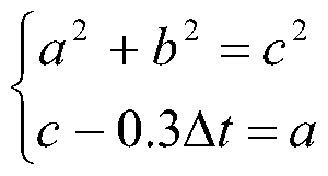
- calculating the distance from the partial discharge source to the fifth position point and the distance from the partial discharge source to the sixth position point according to the time difference and the predetermined distance include: Solve the following equations to calculate the distance from the local discharge source to the fifth position and the sixth position: where a is the distance from the local power supply to the fifth position, b is the predetermined distance, and c is the local power supply to the first The distance between the six position points, A t is the time difference.
- the method further comprises: detecting whether the acquired intensity of the UHF partial discharge signal is greater than a preset signal strength; When the intensity of the partial discharge signal is less than the preset signal strength, a UHF wideband signal amplifier is respectively disposed between the UHF sensor and the oscilloscope. According to another aspect of the present invention, a positioning system for a partial discharge source is also provided.
- the positioning system of the partial discharge power source comprises: a first UHF sensor and a second UHF sensor, wherein the first UHF sensor and the second UHF sensor have the same measurement parameters, respectively, for acquiring the UHF partial discharge signal; the two-channel oscilloscope, a long RF coaxial cable is respectively connected to the first UHF sensor and the second UHF sensor for outputting a waveform of the UHF partial discharge signal acquired by the first UHF sensor and the second UHF sensor;
- the waveforms of the UHF partial discharge signals acquired by the first UHF sensor and the second UHF sensor for the dual-channel oscilloscope output coincide, determine the distance between the local discharge source and the local UHF sensor in the device to be tested and the local discharge power to The distance of the second UHF sensor is equal.
- the local discharge power supply positioning system further includes: a first UHF wideband signal amplifier disposed between the dual channel oscilloscope and the first UHF sensor; and a second UHF wideband signal amplifier disposed on the dual channel oscilloscope and the second UHF sensor between.
- FIG. 1a and FIG. 1b are waveform diagrams of two UHF partial discharge signals actually measured in the prior art
- FIG. 2 is a schematic diagram of a positioning system of a partial discharge source according to an embodiment of the present invention
- 3 is a schematic diagram of determining a first vertical plane according to a local power source positioning method according to an embodiment of the present invention.
- FIG. 4 is a schematic diagram of determining a mid-surface intersection line according to a local power source positioning method according to an embodiment of the present invention
- FIG. 6 is a schematic diagram of a method for positioning a local power source according to an embodiment of the present invention, which is assisted by triangular time difference.
- FIG. 2 is a schematic diagram of a positioning system for a partial discharge source according to an embodiment of the present invention.
- a positioning system for a partial discharge source according to an embodiment of the present invention is shown.
- the first UHF sensor 11 and the second UHF sensor 12 are respectively configured to obtain a UHF partial discharge signal; the first UHF sensor 11 and the second UHF sensor 12 are respectively connected to the dual channel oscilloscope 13 through the RF coaxial cable 14
- the coaxial cable 14 connected to the first UHF sensor 11 and the second UHF sensor 12 is equal in length, so as to avoid the positioning accuracy degradation caused by the inconsistent attenuation of the UHF partial discharge signal caused by the length of the cable. .
- the two-channel oscilloscope 13 is configured to output waveforms of the UHF partial discharge signals acquired by the first UHF sensor 11 and the second UHF sensor 12.
- the computing device (not shown), when the waveform of the UHF partial discharge signal obtained by the first UHF sensor and the second UHF sensor obtained by the two-channel oscilloscope is coincident, determining the local power supply to the device to be tested.
- the distance of a UHF sensor is equal to the distance from the local discharge source to the second UHF sensor. Therefore, the positioning calculation of the local discharge power source can be performed by using the acquired signal waveform.
- the local discharge power source positioning system of the embodiment of the present invention may further include: a first UHF wideband signal amplifier disposed in the dual channel oscilloscope 13 and the first UHF sensor 11 Between, for amplifying the UHF partial discharge signal acquired by the first UHF sensor 11; a second UHF wideband signal amplifier disposed between the two-channel oscilloscope 13 and the second UHF sensor 12 for amplifying The UHF sensor 12 acquires the UHF partial discharge signal, wherein the amplification of the first UHF wideband signal amplifier and the second UHF wideband signal amplifier need to be the same.
- the positioning system of the partial discharge power source of the above embodiment can conveniently realize the precise positioning of the local discharge power source, and has the characteristics of simple structure, convenient implementation and accurate positioning.
- the embodiment of the present invention further provides a local power source positioning method, and the local power source positioning method is a specific use method of the local power source positioning system of the above embodiment.
- the positioning method of the local discharge power source of the embodiment of the invention comprises: setting two identical UHF sensors on the opposite side of the device to be tested to obtain the UHF partial discharge signal; moving the UHF sensor along the connection of two identical UHF sensors One or two of them are simultaneously outputted by the oscilloscope 13 respectively connected to the UHF sensor, and the UHF partial discharge signal is obtained; when the signal waveforms of the UHF partial discharge signals acquired by the two identical UHF sensors coincide, it is determined
- the local power source in the device under test is equal to the distance between the first location point and the second location point where the two same UHF sensors are currently located.
- the first UHF sensor 11 and the second UHF sensor 12 may be respectively disposed on both sides of the device to be tested, along the connection of the first UHF sensor 11 and the second UHF sensor 12, and simultaneously move the two UHF sensors or One of the two UHF sensors simultaneously observes the signal of the UHF partial discharge signal acquired by the two UHF sensors on the oscilloscope 13 when the signal waveforms acquired by the two sensors coincide, indicating that the local power is discharged to the two Only the distance of the sensor is equal, that is, the local power supply to the first UHF in the device under test
- the distance L1 of the first position point where the sensor 11 is currently located is the distance L2 from the local power source in the device under test to the second position point where the second UHF sensor 12 is currently located, and the sizes of the two distances are equal.
- the distance between the first position point and the partial discharge power source to the first position point where the first UHF sensor 11 is currently located, and the second position point and the partial discharge power source can be utilized.
- the distance L2 of the second position point where the second UHF sensor 12 is currently located is convenient for accurately obtaining the local power supply of the device. Since the points equal to the distance between the two positions are composed of the mid-vertical planes of the two position points, preferably, the power source is locally placed in the device to be tested to the first position where the two same UHF sensors are currently located.
- the method may further include: calculating a mid-vertical plane of the connection between the first location point and the second location point, using the mid-vertical plane as the first vertical plane 31, the device to be tested
- the local partial discharge source is located in the first mid-surface 31.
- the calculation of the above distance and the calculation of the determination of the vertical plane can be performed automatically by the above computing device.
- 3 is a schematic diagram of determining a first vertical plane by a positioning method of a partial discharge source according to an embodiment of the present invention. By detecting a first location point and a second location point, a first location point and a second location point may be obtained.
- the first vertical plane 31 of the line segment, the intersection of the first vertical plane 31 and the device to be tested is a partial discharge source.
- the waveform of the emitted electrical signal is consistent, using two identical UHF sensors to detect the position of the waveform consistent position, using the detection to obtain the position point to determine the local
- the plane where the power supply is placed does not need to obtain the time difference of measuring the UHF partial discharge signal during the positioning process, and is not affected by the interference signal caused by the signal propagation path and the signal deflection and the like, and the operation is simple and flexible, and the positioning is accurate.
- the partial discharge power may not be determined simply by the intersection of the first vertical surface 31 and the device to be tested.
- the method further includes: providing two identical UHF sensors in the first central plane 31 to obtain the ultra high frequency from both sides of the device to be tested.
- Partial discharge signal moving one or both of the UHF sensors along the line connecting the two UHF sensors in the first central plane 31, while outputting the obtained UHF portion through the oscilloscope 13 respectively connected to the UHF sensor a discharge signal; when it is detected that the signal waveforms of the UHF partial discharge signals acquired by the two identical UHF sensors coincide, determining that the local discharge source in the device under test is in the first vertical plane 31 and to the same UHF The distance between the third position point and the fourth position point where the sensor is currently located is equal. Using the above steps, another mid-vertical plane can be determined.
- FIG. 4 is a schematic diagram of determining a line of intersection of a vertical plane in a positioning method of a partial discharge source according to an embodiment of the present invention, and calculating a mid-surface of a line connecting a third position point and a fourth position point, as shown in the figure,
- the vertical surface serves as the second intermediate surface 32, and it can be determined that the partial discharge source in the device under test is located on the intersection 41 of the first mid-surface 31 and the second vertical plane 32.
- the above steps are actually repeating the detection process on the other side of the device to be tested, and the position of the partial discharge is determined by the intersection line 41 of the vertical plane obtained by the two probes. If the device to be tested is three-dimensional, and a certain space is occupied in the three-dimensional space, the partial discharge source may not be determined by the intersection line 41 of the two vertical planes. In this case, the test can be further repeated, and the position at which the partial discharge signal occurs is directly obtained on the above-mentioned intersection line 41.
- the method may further include: setting two identical UHF sensors on the intersection line 41 from the to-be-tested Obtaining a UHF partial discharge signal on both sides of the device; moving one or both of the UHF sensors along the intersection line 41, and simultaneously outputting the obtained UHF partial discharge signal through the oscilloscope 13 respectively connected to the UHF sensor; When the signal waveforms of the UHF partial discharge signals acquired by the two identical UHF sensors coincide, it is determined that the local discharge power source in the device under test is located at the midpoint of the connection of the current position of the two identical UHF sensors.
- FIG. 5 is a schematic diagram of determining the intersection point by the positioning method of the partial discharge source according to the embodiment of the present invention.
- the first UHF sensor 11 is disposed on the intersection line 41.
- the second UHF sensor 12 repeats the operation of moving the sensor above, and the midpoint of the two position points having the same waveform is the exact position of the local discharge source.
- the interval of the power supply on the intersection line 41 is determined, for example, the first UHF sensor 11 is placed at one end point on the intersection line 41, and the second UHF sensor 12 is along the intersection line 41 from the end point.
- the time difference of the signal waveform obtained by the two sensors becomes larger and smaller from 0, it means that the power supply is located in the section between the two sensors, if the difference between the two signals becomes more and more If it is large, the discharge source is located on the extension line of the moving direction of the second UHF sensor 12.
- the three-dimensional spatial position of the partial discharge source can be obtained by applying the triangular time difference positioning method.
- FIG. 6 is a schematic diagram of a positioning method of a partial discharge power supply according to an embodiment of the present invention, which is a triangular time difference assisted positioning. As shown, a first UHF sensor 11 is disposed on the intersection line 41, and the setting of the first UHF sensor 11 is recorded.
- the position is a fifth position point; a second UHF sensor 12 having the same parameter as the first UHF sensor 11 is disposed at a predetermined distance from the fifth position point, and the set position of the second UHF sensor 12 is recorded as the sixth position point; Taking the first UHF sensor 11 and the second UHF sensor 12 to receive the time difference of the UHF partial discharge signal; calculating the distance from the local discharge source to the fifth position point and the partial discharge source according to the time difference and the predetermined distance The distance to the sixth position point; the local discharge source is determined on the intersection line 41 according to the distance from the partial discharge source to the fifth position point and the distance from the partial discharge source to the sixth position point.
- the distance between the local discharge source and the fifth position point and the distance from the local power supply to the sixth position point are calculated according to the time difference and the predetermined distance: Solving the following equations and calculating the partial discharge power to the fifth position The distance between the point and the sixth position: In the formula, a is the distance from the local discharge source to the fifth position point, b is the predetermined distance, c is the distance from the partial discharge source to the sixth position point, and At is the time difference.
- a is the distance from the local discharge source to the fifth position point
- b is the predetermined distance
- c is the distance from the partial discharge source to the sixth position point
- At is the time difference.
- the determination of the above vertical plane, the determination of the intersection line, and the calculation of the triangular time difference assisted positioning can all be automatically performed by the computing device.
- the partial discharge when the partial discharge is weak, when the oscilloscope 13 cannot effectively detect the UHF discharge signal, it can be used in UHF.
- a UHF wideband signal amplifier is respectively disposed between the sensor and the oscilloscope 13.
- the specific operation step is to output the obtained UHF partial discharge signal through the oscilloscope 13 respectively connected to the UHF sensor, and further includes: detecting the obtained UHF partial discharge Whether the strength of the signal is greater than the preset signal strength; when the intensity of the UHF partial discharge signal is less than the preset signal strength, a UHF wideband signal amplifier is respectively disposed between the UHF sensor and the oscilloscope 13.
- the above preset signal strength can be set according to the detection accuracy of the oscilloscope 13.
- the above oscilloscope 13 since the frequency of the UHF discharge signal is high, the above oscilloscope 13 must tell the oscilloscope 13 that it has at least two scans.
- the parameters of the first UHF sensor 11 and the second UHF sensor 12 described above must be identical. In the case where a UHF wideband signal amplifier is provided, the amplification gain and delay must also be the same.
- the first UHF sensor 11 is arranged, the receiving directions of the two sensors are opposite, so that there is no other obstruction as much as possible except for the detected power device. At this time, the oscilloscope 13 can observe a more obvious partial discharge UHF. signal.
- a specific case of using the local power source positioning method of the embodiment will be described below. The steps are as follows:
- step S11 the receiving directions of the two sensors are maintained such that the distance between the two ranges from several meters to several tens of meters.
- the position of the two sensors is moved in three dimensions, the starting points of the two UHF partial discharge signals displayed by the oscilloscope 13 are coincident, the positions of the two sensors are recorded, and the first vertical plane 31 perpendicular to the line is found and recorded.
- step S12 the positions of the two sensors are moved according to the situation of the on-site space, and it is preferable to make the connection 32 of the two sensors perpendicular to the connection 31.
- the second mid-surface 32 is determined in the same manner as step S11.
- step S13 the first central plane 31 and the second central plane 32 intersect at an intersection line 41, which may be perpendicular to the horizontal plane or may have a certain angle with the horizontal plane. At this point, it can be determined that the discharge source is located at the intersection line 41 or its extension line.
- Step S14 if necessary, two sensors are arranged in the parallel direction of the intersection line 41, and the third vertical plane is determined by the same method as step S11, and intersects the intersection line 41 at a certain point, which is the three-dimensional power supply. Spatial location.
- step S15 when the step of step S14 is limited by space, the triangular time difference positioning method is applied to perform auxiliary calculation, and the calculation formula is as described above, so that the three-dimensional space of the discharge source can be accurately positioned.
- step S16 the receiving directions of the two sensors are the same, and are located in the same receiving plane, and the receiving directions of the two sensors are simultaneously adjusted on the spherical or hemispherical surface of the space, and the receiving direction of the detection signal is relatively strong, and the oscilloscope 13 displays two paths. The signals coincide.
- the results of measurements on the GIS equipment at the substation site show that the above positioning method and positioning system are accurate and the detection effect is good.
- the technical solution of the embodiment does not need to measure the time difference of two UHF partial discharge signals, and does not need to consider the propagation speed of the electromagnetic wave signal, and does not need to be calculated.
- the problem of accurately measuring the time difference of the UHF partial discharge signal is fundamentally solved, and the problem of poor positioning accuracy of the dual sensor caused by factors such as signal propagation path and signal bounce.
- the embodiment is simple in operation, convenient to implement, and accurate in positioning, and realizes three-dimensional spatial positioning of the local discharge power source by using only two UHF sensors. It has significant practical significance for the detection, location and elimination of interference signals of partial discharge of power transmission and transformation equipment.
- the same UHF sensor is used to detect the position of the waveform, and the position is obtained by the detection.
- the plane where the local power supply is located is determined.
- the time difference of measuring the UHF partial discharge signal is not required, and the interference signal caused by the signal propagation path and the signal bounce reflection is not affected, and the operation is simple and flexible, and the positioning is accurate.
- the computing device may be implemented by program code executable by the computing device, such that they may be stored in the storage device by the computing device, or they may be separately fabricated into respective integrated circuit modules. Blocks, or a plurality of modules or steps in them, are implemented as a single integrated circuit module.
- the invention is not limited to any specific combination of hardware and software. The above is only the preferred embodiment of the present invention, and is not intended to limit the present invention, and various modifications and changes can be made to the present invention. Any modifications, equivalent substitutions, improvements, etc. made within the spirit and scope of the present invention are intended to be included within the scope of the present invention.
Landscapes
- Physics & Mathematics (AREA)
- General Physics & Mathematics (AREA)
- Testing Relating To Insulation (AREA)
- Locating Faults (AREA)
Abstract
本发明提供了一种局部放电源的定位方法和局部放电源的定位系统。该局部放电源的定位方法包括:在待测设备的相对面设置两个同样的UHF传感器获取特高频局部放电信号;沿两个同样的UHF传感器的连线移动两个同样的UHF传感器中的一个或两个,同时通过分别与两个同样的UHF传感器连接的示波器输出获取到的特高频局部放电信号;当两个同样的UHF传感器获取到的特高频局部放电信号的信号波形重合时,确定待测设备中局部放电源到两个同样的UHF传感器当前所在的第一位置点和第二位置点的距离相等。利用本发明的方案,定位过程中不需要获取测量特高频局部放电信号的时差,也不受信号传播路径及信号折反射等因素导致的干扰信号的影响,操作简便灵活,定位精确。
Description
局部放电源的定位方法和局部放电源的定位系统 技术领域 本发明涉及高电压及绝缘领域, 具体而言, 涉及一种局部放电源的定位方法和局 部放电源的定位系统。 背景技术 随着社会对电力需求的不断增大, 电力产业得到快速发展, 大型输电网络的安全 运行成为电力行业关注的重大问题, 而输变电设备的健康状态则是电网安全稳定运行 的关键因素。 研究表明, 输变电设备以绝缘故障为多, 而绝缘故障的先兆往往表现为 局部放电。 一般认为, 电力设备中的局部放电是设备隐患的重要表征形式, 局部放电 不但会严重影响电场分布, 导致电场畸变, 而且会使绝缘材料腐蚀, 最终引发绝缘击 穿, 导致设备故障。 特高频、 超声波、 红外、 紫外等带电检测技术和在线监测技术在电力设备检测领 域得到了广泛应用, 并取得了较为显著的成效。 在上述多种状态检测技术当中, 特高 频局部放电检测 UHF (Ultra High Frequency) 技术的特点在于: 检测频段较高, 可以 有效地避开常规局部放电测量中的电晕、 开关操作等多种电气干扰; 检测频带宽, 检 测灵敏度很高; 可识别故障类型和进行定位; 此外, 与其他方法不同, 特高频法测得 的波形更加符合实际的放电波形, 可以较全面的研究局部放电的本质特征。 特高频检 测技术的特点使其在局部放电检测领域具有其他方法无法比拟的优点, 因而在近年来 在局部放电检测领域得到了迅速的发展和广泛的应用。 特高频局部放电检测方法的主 要检测对象包括: 电力变压器、断路器、气体绝缘开关 GIS (Gas Insulated Switchgear)、 开关柜、 高压电缆等。 特高频法检测电力设备中的局部放电是 20 世纪 80 年代初期由英国中央电力局 (Central Electricity Generating Board-CEGB)提出的,该方法由 Scottish Power于 1986 年应用于英国的 Tomess电站 420kV GIS设备的检测。 Tomess电站的多年运行经验验 证了该方法的可行性, 使特高频法得到了行业的认可, 并成为近 20年以来 GIS绝缘 检测的研究热点之一。 其中以英国 Strathclyde大学、 日本 Nagoya大学、 德国 Stuttgart 大学、 荷兰 Delft大学、 韩国 Hanyang University大学的研究工作最为突出。 除大学和 研究所以外, 一些大型电力设备制造公司, 如英国的 Rolls Royce Ltd.、 DMS, 德国的 Siemens AG,瑞士的 ABB,法国的 ALSTOMT&D和日本的 Mitsubishi Toshiba^ Tokyo
Electric Power Company AE Power Systems Corporation,韩国的 Power System Diagnosis Tech、 HYOSUNG Corporation, 澳大利亚的 Powerlink Queensland Ltd.等公司也参与了 特高频法的研究和推广, 加速了该技术的发展与应用。 我国的超高频检测技术起步较 晚, 一些大学和研究所于 20世纪 90年代初期才开始对特高频法进行研究, 目前也取 得了一定的进展。 如西安交通大学、 清华大学、 重庆大学、 华北电力大学、 上海交通 大学等。 在特高频局部放电检测技术的实际应用当中, 放电源的定位是关键问题之一。 这 是因为放电源的准确定位不仅可以找到电力设备缺陷或隐患的准确位置, 而且能够通 过有效识别放电源的位置, 进而判断该放电是外部干扰还是设备内部放电。 因此, 基 于特高频局部放电检测技术的放电源准确定位方法十分重要。 目前, 基于特高频的局 部放电定位方法有信号幅度比较法、 信号先后比较法、 时间差计算法和特高频传感器 阵列法等。 以下对常见的几种基于特高频的局部放电定位方法进行介绍: 一、 信号幅度比较法。 信号幅度比较法是利用特高频电磁波信号在传播过程中的 衰减特点, 把传感器分别放在的各个盘式绝缘子处, 比较各处所测到的信号的大小, 信号幅值大, 则意味着距离局部放电源近信号幅值小, 则传感器距离局部放电源远, 信号最大的盘式绝缘子的位置即为靠近放电源的位置。 信号幅度比较法定位对传感器 的性能要求比较高, 传感器的增益需要相等, 而且要求信号具有明显的衰减特征, 因 此只能用于信号的粗略定位。 二、 信号先后比较法。 传感器从多个盘式绝缘子处接收的放电信号的幅值, 有时 无明显差别, 很难从信号的幅值上确定局部放电的位置。 这时可以根据传感器接收信 号的先后确定局部放电的位置。 具体方法是把传感器 A、 B分开放置, 如果总是 A传 感器的信号先于 B传感器, 则表明放电源在 A传感器的附近, 移动 B传感器向 A靠 近, 观察 A、 B传感器信号到达的先后, 可以确定局部放电的大致位置。 以上信号幅度比较法、 信号先后比较法受到信号传播与衰减路径等因素的影响, 只能用于放电源的粗略定位, 定位精度差。 另外, 以上两种方法无法实现放电源的三 维定位, 信号传播路径的复杂性以及信号折反射等因素也会导致该方法的定位精度较 差。 三、 时间差计算法。 时间差计算法可以精确的测量两个传感器接收到信号的时间 差, 根据电磁波的传播速度, 计算放电源的位置。 电磁波在气室中传播, 对于不同的 传感器而言, 接收到局部放电信号的时间不一样, 利用传感器之间的距离和信号到达 传感器的时间差可以确定局部放电的位置。
2003年, L. Yang和 M.D. Judd提出了基于最短光程原理采用特高频法对变压器 局部放电进行定位的思想。 他们在屏蔽室内通过长方体、 圆柱体等简单几何形体的金 属障碍物验证了最短光程原理的正确性, 试验误差仅为数厘米。 Judd还用时域有限差 分方法仿真了存在导电圆柱情况下电磁波绕射传播过程, 从理论角度探索了根据最短 光程原理进行局部放电定位的可行性。 同时 M.DJudd课题组把特高频信号能量累积 图的"拐点"作为计算时间差的参考点, 根据三个不同位置的传感器获得三组时间差进 行定位。 然而, 时间差计算法在实际检测定位过程中的关键问题在于准确确定两个特高频 信号的波头, 即如何准确计算两者的时间差。 在实际检测过程中很难精确测量信号时 差。 现场实际测试过程中, 所测量的信号往往受到反射、 折射等因素的影响, 得到的 是一个叠加的信号, 很难确定两个信号的波头, 即精确读取两个信号的时差, 从而给 定位方法的实施及定位结果的准确性带来了很大的困难。 图 la和图 lb是现有技术中实际测量得到的两个特高频局部放电信号的波形图, 由图可见, 很难测量两个信号的准确时差。 另外, 该方法也无法实现放电源的三维定 位, 信号传播路径的复杂性以及信号折反射等因素也会导致该方法的定位精度较差。 四、基于相控阵理论的定位法。该方法是根据相控阵理论, 采用一个 NxN阵元的 平面相控阵传感器作为接收信号用传感器。 NxN个阵元对局部放电源的接收信号的空 间相位差可表示成矩阵, 对 NxN个阵元接收信号的附加阵内相位差也可表示成矩阵。 改变阵内相位矩阵, 传感器传感器方向图就按照 p= kdsin6, a= kdcosesincp对应的 θ、 φ 方向扫描。 同时通过近似连续改变平面阵的阵内水平和垂直相位差, 就可以实现空 间坐标上的电控扫描, 获取空间上的目标信息。 式中 α、 β为相邻阵元的阵内相位差, 即相位延迟, θ、 φ分别为相控阵的仰角和方位角。 将局部放电看作超高频和超声波的发射源, 用检测超高频和超声波信号的相控阵 构成平面传感器, 以接收到的超高频信号作为时间基准, 进而得到同一方向的超声波 传输时延, 这样可先计算出局部放电点与传感器的距离, 然后根据相控阵扫描的方位 角和仰角即可得出放电点的空间几何位置。 然而, 基于相控阵理论的定位法在实际检测定位过程中的关键问题不仅在于准确 测量两个特高频信号的时差, 还要准确测量传感器的方位角和仰角, 以及精准的计算 方法。 这种方法虽然能够实现放电源的三维定位, 但需要安装的特高频传感器数量较 多, 而且对安装位置及安装角度的精度要求较高, 理论计算方法复杂, 同样存在精确 测量信号时差困难的问题。
从以上分析可以看出时间差计算法和基于相控阵理论定位法应用于现场检测是, 对传感器的安装的精度要求较高, 理论计算方法复杂, 现场实施同样存在较大的局限 性。 针对上述现有技术中特高频局部放电定位方法现场实施中对传感器安装精度要求 高的问题, 尚未提出有效的解决方案。 发明内容 本发明旨在提供一种局部放电源的定位方法和局部放电源的定位系统, 以解决现 有技术中现场实施中对传感器安装精度要求高问题。 为了实现上述目的,根据本发明的一个方面,提供了一种局部放电源的定位方法。 该局部放电源的定位方法,包括: 在待测设备的相对面设置两个同样的 UHF传感器获 取特高频局部放电信号; 沿两个同样的 UHF传感器的连线移动两个同样的 UHF传感 器中的一个或两个,同时通过分别与两个同样的 UHF传感器连接的示波器输出获取到 的特高频局部放电信号;当两个同样的 UHF传感器获取到的特高频局部放电信号的信 号波形重合时,确定待测设备中局部放电源到两个同样的 UHF传感器当前所在的第一 位置点和第二位置点的距离相等。 进一步地,在确定待测设备中局部放电源到两个同样的 UHF传感器当前所在的第 一位置点和第二位置点的距离相等之后还包括: 计算第一位置点和第二位置点的连线 的中垂面, 将该中垂面作为第一中垂面, 待测设备中局部放电源位于第一中垂面内。 进一步地, 在将该中垂面作为第一中垂面之后还包括: 在第一中垂面内设置两个 同样的 UHF传感器从待测设备的两侧获取特高频局部放电信号; 沿两个同样的 UHF 传感器在第一中垂面内的连线移动 UHF传感器中的一个或两个,同时通过分别与 UHF 传感器连接的示波器输出获取到的特高频局部放电信号; 当检测到两个同样的 UHF 传感器获取到的特高频局部放电信号的信号波形重合时, 确定待测设备中局部放电源 在第一中垂面内且到两个同样的 UHF 传感器当前所在的第三位置点和第四位置点的 距离相等。 进一步地, 在确定待测设备中局部放电源在第一中垂面内且到两个同样的 UHF 传感器当前所在的第三位置点和第四位置点的距离相等之后还包括: 计算第三位置点 和第四位置点的连线的中垂面, 将该中垂面作为第二中垂面, 确定待测设备中局部放 电源位于第一中垂面和第二中垂面的交线上。
进一步地, 在确定待测设备中局部放电源位于第一中垂面和第二中垂面的交线上 之后还包括:在交线上设置两个同样的 UHF传感器从待测设备的两侧获取特高频局部 放电信号;沿交线移动两个同样的 UHF传感器中的一个或两个,同时通过分别与 UHF 传感器连接的示波器输出获取到的特高频局部放电信号; 当检测到两个同样的 UHF 传感器获取到的特高频局部放电信号的信号波形重合时, 确定待测设备中局部放电源 位于两个同样的 UHF传感器的当前位置连线的中点处。 进一步地, 在确定待测设备中局部放电源位于第一中垂面和第二中垂面的交线上 之后还包括: 在交线上设置第一 UHF传感器, 记录第一 UHF传感器的设置位置为第 五位置点;在距离第五位置点预定距离的任意位置设置与第一 UHF传感器参数相同的 第二 UHF传感器, 记录第二 UHF传感器的设置位置为第六位置点; 读取第一 UHF 传感器和第二 UHF传感器接收到特高频局部放电信号的时间差;根据时间差和预定距 离计算得出局部放电源到第五位置点的距离和局部放电源到第六位置点的距离; 根据局部放电源到第五位置点的距离和局部放电源到第六位置点的距离在交线上 确定局部放电源。 进一步地, 根据时间差和预定距离计算得出局部放电源到第五位置点的距离和局 部放电源到第六位置点的距离包括:
 求解以下方程组计算得出局部放电源到第五位置点和第六位置点的距离: 其中, a 为局部放电源到第五位置点的距离, b为预定距离, c为局部放电源到第六位置点的距 离, A t为时间差。 进一步地,在通过分别与 UHF传感器连接的示波器输出获取到的特高频局部放电 信号之后还包括:检测获取到的特高频局部放电信号的强度是否大于预设的信号强度; 当特高频局部放电信号的强度小于预设的信号强度时,在 UHF传感器和示波器之间分 别设置 UHF宽带信号放大器。 根据本发明的另一个方面, 还提供了一种局部放电源的定位系统。 该局部放电电 源的定位系统包括: 第一 UHF传感器和第二 UHF传感器, 第一 UHF传感器和第二 UHF传感器的测量参数相同, 分别用于获取特高频局部放电信号; 双通道示波器, 通 过等长的射频同轴电缆分别与第一 UHF传感器和第二 UHF传感器连接, 用于输出第 一 UHF传感器和第二 UHF传感器获取到的特高频局部放电信号的波形; 计算装置,
用于双通道示波器输出的第一 UHF传感器和第二 UHF传感器获取到的特高频局部放 电信号的波形重合时,确定待测设备中局部放电源到第一 UHF传感器的距离和局部放 电源到第二 UHF传感器的距离相等。 进一步地, 该局部放电电源的定位系统还包括: 第一 UHF宽带信号放大器, 设置 在双通道示波器和第一 UHF传感器之间; 第二 UHF宽带信号放大器, 设置在双通道 示波器和第二 UHF传感器之间。 应用本发明的技术方案, 利用距离局部放电的位置到距离相等的位置处, 发出的 电信号的波形一致的特点,使用两个同样的 UHF传感器探测波形一致的位置点,利用 探测得出位置点确定局部放电源所在平面, 定位过程中不需要获取测量特高频局部放 电信号的时差, 也不受信号传播路径及信号折反射等因素导致的干扰信号的影响, 操 作简便灵活, 定位精确。 附图说明 构成本申请的一部分的说明书附图用来提供对本发明的进一步理解, 本发明的示 意性实施例及其说明用于解释本发明, 并不构成对本发明的不当限定。 在附图中: 图 la和图 lb是现有技术中实际测量得到的两个特高频局部放电信号的波形图; 图 2是根据本发明实施例的局部放电源的定位系统的示意图; 图 3是根据本发明实施例的局部放电源的定位方法确定第一中垂面的示意图 图 4是根据本发明实施例的局部放电源的定位方法确定中垂面交线的示意图; 图 5是根据本发明实施例的局部放电源的定位方法确定交点的示意图; 图 6是根据本发明实施例的局部放电源的定位方法是用三角形时差辅助定位的原 理图。 具体实施方式 需要说明的是, 在不冲突的情况下, 本申请中的实施例及实施例中的特征可以相 互组合。 下面将参考附图并结合实施例来详细说明本发明。 本发明实施例提供了一种局部放电源的定位系统, 图 2是根据本发明实施例的局 部放电源的定位系统的示意图, 如图 2所示, 本发明实施例的局部放电源的定位系统
包括: 第一 UHF传感器 11和第二 UHF传感器 12, 分别用于获取特高频局部放电信 号;该第一 UHF传感器 11和第二 UHF传感器 12分别通过射频同轴电缆 14与双通道 示波器 13连接, 优选地,双通道示波器 13与第一 UHF传感器 11和第二 UHF传感器 12连接的同轴电缆 14长度相等, 从而避免线缆的长度引起的特高频局部放电信号衰 减不一致引起的定位精度下降。 该双通道示波器 13, 用于输出第一 UHF传感器 11和 所述第二 UHF传感器 12获取到的特高频局部放电信号的波形。 计算装置 (图中未示 出),用于双通道示波器输出的第一 UHF传感器和第二 UHF传感器获取到的特高频局 部放电信号的波形重合时,确定待测设备中局部放电源到第一 UHF传感器的距离和局 部放电源到第二 UHF传感器的距离相等。从而利用获取到的信号波形可以进行局部放 电源的定位计算。 在特高频局部放电信号的信号强度较弱的情况下, 本发明实施例的局部放电源的 定位系统还可以包括:第一 UHF宽带信号放大器,设置在双通道示波器 13和第一 UHF 传感器 11之间, 用于放大第一 UHF传感器 11获取到的特高频局部放电信号; 第二 UHF宽带信号放大器, 设置在所述双通道示波器 13和所述第二 UHF传感器 12之间, 用于放大第而 UHF传感器 12获取到的特高频局部放电信号,其中第一 UHF宽带信号 放大器和第二 UHF宽带信号放大器的放大倍数需要相同。 使用上述实施例的局部放电源的定位系统, 可以方便地实现局部放电源的精确定 位, 具有结构简单、 实施方便、 定位精确的特点。 本发明的实施例还提供了一种局部放电源的定位方法, 该局部放电源的定位方法 是上述实施例的局部放电源的定位系统的具体使用方法。 本发明的实施例的局部放电源的定位方法包括: 在待测设备的相对面设置两个同 样的 UHF 传感器获取特高频局部放电信号; 沿两个同样的 UHF 传感器的连线移动 UHF传感器中的一个或两个, 同时通过分别与 UHF传感器连接的示波器 13输出获取 到的特高频局部放电信号;当两个同样的 UHF传感器获取到的特高频局部放电信号的 信号波形重合时,确定待测设备中局部放电源到两个同样的 UHF传感器当前所在的第 一位置点和第二位置点的距离相等。 具体地,可以在待测设备的两侧分别布置第一 UHF传感器 11和第二 UHF传感器 12, 沿第一 UHF传感器 11和第二 UHF传感器 12的连线, 同时移动这两个 UHF传感 器或者这两个 UHF传感器之一,同时在示波器 13上观察这两个 UHF传感器获取到的 特高频局部放电信号的信号勃兴, 当两个传感器获取到的信号波形重合时, 说明局部 放电源到这两只传感器的距离是相等的, 也就是待测设备中局部放电源到第一 UHF
传感器 11当前所在的第一位置点的距离 Ll,待测设备中局部放电源到第二 UHF传感 器 12当前所在的第二位置点的距离 L2, 两个距离的大小是相等的。 在待测设备为高压电缆等线状的设备时, 可以利用第一位置点和局部放电源到第 一 UHF传感器 11当前所在的第一位置点的距离 L1以及第二位置点和局部放电源到第 二 UHF传感器 12当前所在的第二位置点的距离 L2,方便精确地得到设备局部放电源。 由于到两个位置点距离相等的点组成的是两个位置点连线的中垂面, 优选地, 在 确定待测设备中局部放电源到两个同样的 UHF 传感器当前所在的第一位置点和第二 位置点的距离相等之后, 本方法还可以包括: 计算第一位置点和第二位置点的连线的 中垂面, 将该中垂面作为第一中垂面 31, 待测设备中局部放电源位于第一中垂面 31 内。 以上距离的计算以及确定中垂面的计算可以有上面的计算装置自动进行。 图 3是根据本发明实施例的局部放电源的定位方法确定第一中垂面的示意图, 通 过探测确定第一位置点和第二位置点, 可以得到第一位置点和第二位置点之间线段的 第一中垂面 31, 该第一中垂面 31与待测设备的交点即为局部放电源。 应用这种方法, 利用距离局部放电的位置到距离相等的位置处, 发出的电信号的 波形一致的特点,使用两个同样的 UHF传感器探测波形一致的位置点,利用探测得出 位置点确定局部放电源所在平面, 定位过程中不需要获取测量特高频局部放电信号的 时差, 也不受信号传播路径及信号折反射等因素导致的干扰信号的影响, 操作简便灵 活, 定位精确。 在待测设备为盘式绝缘子、 或 GIS等二维或三维的设备时, 单纯通过第一中垂面 31与待测设备的交点可能无法确定局部放电源。 在这种情况下, 在将该中垂面作为第 一中垂面 31之后还可以包括:在第一中垂面 31内设置两个同样的 UHF传感器从待测 设备的两侧获取特高频局部放电信号; 沿两个同样的 UHF传感器在第一中垂面 31内 的连线移动 UHF传感器中的一个或两个, 同时通过分别与 UHF传感器连接的示波器 13输出获取到的特高频局部放电信号; 当检测到两个同样的 UHF传感器获取到的特 高频局部放电信号的信号波形重合时, 确定待测设备中局部放电源在第一中垂面 31 内且到两个同样的 UHF传感器当前所在的第三位置点和第四位置点的距离相等。 利用上述的步骤可以确定另一个中垂面, 两个面相交与一条线, 也就是放电源应 该位于这条直线上, 结合被测设备的具体结构如盘式绝缘子等二维面型的结构, 可以 确定放电源的具体位置。
图 4是根据本发明实施例的局部放电源的定位方法确定中垂面交线的示意图, 如 图所示, 计算第三位置点和第四位置点的连线的中垂面, 将该中垂面作为第二中垂面 32, 可以确定待测设备中局部放电源位于第一中垂面 31 和第二中垂面 32 的交线 41 上。 以上步骤是实际上待测设备的另一个侧面上重复探测过程, 利用两次探测得到的 中垂面交线 41确定局部放电的位置点。 待测设备为立体的, 三维空间内均占用一定空间的情况下, 通过两个中垂面的交 线 41也可能无法确定局部放电源。在这种情况下, 可以进一步重复测试, 在上述交线 41上直接得到发生局部放电信号的位置。 因此, 在确定待测设备中局部放电源位于第 一中垂面 31和第二中垂面 32的交线 41上之后还可以包括: 在交线 41上设置两个同 样的 UHF传感器从待测设备的两侧获取特高频局部放电信号; 沿交线 41 移动 UHF 传感器中的一个或两个, 同时通过分别与 UHF传感器连接的示波器 13输出获取到的 特高频局部放电信号;当检测到两个同样的 UHF传感器获取到的特高频局部放电信号 的信号波形重合时,确定待测设备中局部放电源位于两个同样的 UHF传感器的当前位 置连线的中点处。 三个面相交于一点, 便是局部放电源的位置 图 5是根据本发明实施例的局部放电源的定位方法确定交点的示意图,如图所示, 在交线 41上设置第一 UHF传感器 11和第二 UHF传感器 12, 重复上面移动传感器的 操作, 波形相同的两个位置点的中点即为局部放电源的准确位置。 当受到高度原因、 变电站建筑物或设备阻碍, 难以实现在三维空间内重复三次探 测过程的情况下, 可以辅助应用三角形时差定位法得到局部放电源的三维空间位置。 具体操作时, 首先, 确定放电源在上述交线 41上的区间, 例如将第一 UHF传感器 11 放置在交线 41上的一个端点处, 第二 UHF传感器 12由该端点处沿上述交线 41向一 个固定方向移动, 若两个传感器得到的信号波形的时差从 0变大又变小, 则说明放电 源位于两传感器之间的区段内, 如果若两信号时差从 0变的越来越大, 则说明放电源 位于第二 UHF传感器 12的移动方向的延长线上。 在放电源在第二 UHF传感器 12的 移动方向的延长线上时,可以应用三角形时差定位法得到局部放电源的三维空间位置。 图 6 是根据本发明实施例的局部放电源的定位方法是用三角形时差辅助定位的原理 图, 如图所示, 在交线 41上设置第一 UHF传感器 11, 记录第一 UHF传感器 11的设 置位置为第五位置点;在距离第五位置点预定距离的任意位置设置与第一 UHF传感器 11参数相同的第二 UHF传感器 12, 记录第二 UHF传感器 12的设置位置为第六位置 点; 读取第一 UHF传感器 11和第二 UHF传感器 12接收到特高频局部放电信号的时 间差; 根据时间差和预定距离计算得出局部放电源到第五位置点的距离和局部放电源
到第六位置点的距离; 根据局部放电源到第五位置点的距离和局部放电源到第六位置 点的距离在交线 41上确定局部放电源。 具体地, 根据时间差和预定距离计算得出局部放电源到第五位置点的距离和局部 放电源到第六位置点的距离的方式为: 求解以下方程组计算得出局部放电源到第五位 置点和第六位置点的距离:
求解以下方程组计算得出局部放电源到第五位置点和第六位置点的距离: 其中, a 为局部放电源到第五位置点的距离, b为预定距离, c为局部放电源到第六位置点的距 离, A t为时间差。 进一步地,在通过分别与 UHF传感器连接的示波器输出获取到的特高频局部放电 信号之后还包括:检测获取到的特高频局部放电信号的强度是否大于预设的信号强度; 当特高频局部放电信号的强度小于预设的信号强度时,在 UHF传感器和示波器之间分 别设置 UHF宽带信号放大器。 根据本发明的另一个方面, 还提供了一种局部放电源的定位系统。 该局部放电电 源的定位系统包括: 第一 UHF传感器和第二 UHF传感器, 第一 UHF传感器和第二 UHF传感器的测量参数相同, 分别用于获取特高频局部放电信号; 双通道示波器, 通 过等长的射频同轴电缆分别与第一 UHF传感器和第二 UHF传感器连接, 用于输出第 一 UHF传感器和第二 UHF传感器获取到的特高频局部放电信号的波形; 计算装置,
用于双通道示波器输出的第一 UHF传感器和第二 UHF传感器获取到的特高频局部放 电信号的波形重合时,确定待测设备中局部放电源到第一 UHF传感器的距离和局部放 电源到第二 UHF传感器的距离相等。 进一步地, 该局部放电电源的定位系统还包括: 第一 UHF宽带信号放大器, 设置 在双通道示波器和第一 UHF传感器之间; 第二 UHF宽带信号放大器, 设置在双通道 示波器和第二 UHF传感器之间。 应用本发明的技术方案, 利用距离局部放电的位置到距离相等的位置处, 发出的 电信号的波形一致的特点,使用两个同样的 UHF传感器探测波形一致的位置点,利用 探测得出位置点确定局部放电源所在平面, 定位过程中不需要获取测量特高频局部放 电信号的时差, 也不受信号传播路径及信号折反射等因素导致的干扰信号的影响, 操 作简便灵活, 定位精确。 附图说明 构成本申请的一部分的说明书附图用来提供对本发明的进一步理解, 本发明的示 意性实施例及其说明用于解释本发明, 并不构成对本发明的不当限定。 在附图中: 图 la和图 lb是现有技术中实际测量得到的两个特高频局部放电信号的波形图; 图 2是根据本发明实施例的局部放电源的定位系统的示意图; 图 3是根据本发明实施例的局部放电源的定位方法确定第一中垂面的示意图 图 4是根据本发明实施例的局部放电源的定位方法确定中垂面交线的示意图; 图 5是根据本发明实施例的局部放电源的定位方法确定交点的示意图; 图 6是根据本发明实施例的局部放电源的定位方法是用三角形时差辅助定位的原 理图。 具体实施方式 需要说明的是, 在不冲突的情况下, 本申请中的实施例及实施例中的特征可以相 互组合。 下面将参考附图并结合实施例来详细说明本发明。 本发明实施例提供了一种局部放电源的定位系统, 图 2是根据本发明实施例的局 部放电源的定位系统的示意图, 如图 2所示, 本发明实施例的局部放电源的定位系统
包括: 第一 UHF传感器 11和第二 UHF传感器 12, 分别用于获取特高频局部放电信 号;该第一 UHF传感器 11和第二 UHF传感器 12分别通过射频同轴电缆 14与双通道 示波器 13连接, 优选地,双通道示波器 13与第一 UHF传感器 11和第二 UHF传感器 12连接的同轴电缆 14长度相等, 从而避免线缆的长度引起的特高频局部放电信号衰 减不一致引起的定位精度下降。 该双通道示波器 13, 用于输出第一 UHF传感器 11和 所述第二 UHF传感器 12获取到的特高频局部放电信号的波形。 计算装置 (图中未示 出),用于双通道示波器输出的第一 UHF传感器和第二 UHF传感器获取到的特高频局 部放电信号的波形重合时,确定待测设备中局部放电源到第一 UHF传感器的距离和局 部放电源到第二 UHF传感器的距离相等。从而利用获取到的信号波形可以进行局部放 电源的定位计算。 在特高频局部放电信号的信号强度较弱的情况下, 本发明实施例的局部放电源的 定位系统还可以包括:第一 UHF宽带信号放大器,设置在双通道示波器 13和第一 UHF 传感器 11之间, 用于放大第一 UHF传感器 11获取到的特高频局部放电信号; 第二 UHF宽带信号放大器, 设置在所述双通道示波器 13和所述第二 UHF传感器 12之间, 用于放大第而 UHF传感器 12获取到的特高频局部放电信号,其中第一 UHF宽带信号 放大器和第二 UHF宽带信号放大器的放大倍数需要相同。 使用上述实施例的局部放电源的定位系统, 可以方便地实现局部放电源的精确定 位, 具有结构简单、 实施方便、 定位精确的特点。 本发明的实施例还提供了一种局部放电源的定位方法, 该局部放电源的定位方法 是上述实施例的局部放电源的定位系统的具体使用方法。 本发明的实施例的局部放电源的定位方法包括: 在待测设备的相对面设置两个同 样的 UHF 传感器获取特高频局部放电信号; 沿两个同样的 UHF 传感器的连线移动 UHF传感器中的一个或两个, 同时通过分别与 UHF传感器连接的示波器 13输出获取 到的特高频局部放电信号;当两个同样的 UHF传感器获取到的特高频局部放电信号的 信号波形重合时,确定待测设备中局部放电源到两个同样的 UHF传感器当前所在的第 一位置点和第二位置点的距离相等。 具体地,可以在待测设备的两侧分别布置第一 UHF传感器 11和第二 UHF传感器 12, 沿第一 UHF传感器 11和第二 UHF传感器 12的连线, 同时移动这两个 UHF传感 器或者这两个 UHF传感器之一,同时在示波器 13上观察这两个 UHF传感器获取到的 特高频局部放电信号的信号勃兴, 当两个传感器获取到的信号波形重合时, 说明局部 放电源到这两只传感器的距离是相等的, 也就是待测设备中局部放电源到第一 UHF
传感器 11当前所在的第一位置点的距离 Ll,待测设备中局部放电源到第二 UHF传感 器 12当前所在的第二位置点的距离 L2, 两个距离的大小是相等的。 在待测设备为高压电缆等线状的设备时, 可以利用第一位置点和局部放电源到第 一 UHF传感器 11当前所在的第一位置点的距离 L1以及第二位置点和局部放电源到第 二 UHF传感器 12当前所在的第二位置点的距离 L2,方便精确地得到设备局部放电源。 由于到两个位置点距离相等的点组成的是两个位置点连线的中垂面, 优选地, 在 确定待测设备中局部放电源到两个同样的 UHF 传感器当前所在的第一位置点和第二 位置点的距离相等之后, 本方法还可以包括: 计算第一位置点和第二位置点的连线的 中垂面, 将该中垂面作为第一中垂面 31, 待测设备中局部放电源位于第一中垂面 31 内。 以上距离的计算以及确定中垂面的计算可以有上面的计算装置自动进行。 图 3是根据本发明实施例的局部放电源的定位方法确定第一中垂面的示意图, 通 过探测确定第一位置点和第二位置点, 可以得到第一位置点和第二位置点之间线段的 第一中垂面 31, 该第一中垂面 31与待测设备的交点即为局部放电源。 应用这种方法, 利用距离局部放电的位置到距离相等的位置处, 发出的电信号的 波形一致的特点,使用两个同样的 UHF传感器探测波形一致的位置点,利用探测得出 位置点确定局部放电源所在平面, 定位过程中不需要获取测量特高频局部放电信号的 时差, 也不受信号传播路径及信号折反射等因素导致的干扰信号的影响, 操作简便灵 活, 定位精确。 在待测设备为盘式绝缘子、 或 GIS等二维或三维的设备时, 单纯通过第一中垂面 31与待测设备的交点可能无法确定局部放电源。 在这种情况下, 在将该中垂面作为第 一中垂面 31之后还可以包括:在第一中垂面 31内设置两个同样的 UHF传感器从待测 设备的两侧获取特高频局部放电信号; 沿两个同样的 UHF传感器在第一中垂面 31内 的连线移动 UHF传感器中的一个或两个, 同时通过分别与 UHF传感器连接的示波器 13输出获取到的特高频局部放电信号; 当检测到两个同样的 UHF传感器获取到的特 高频局部放电信号的信号波形重合时, 确定待测设备中局部放电源在第一中垂面 31 内且到两个同样的 UHF传感器当前所在的第三位置点和第四位置点的距离相等。 利用上述的步骤可以确定另一个中垂面, 两个面相交与一条线, 也就是放电源应 该位于这条直线上, 结合被测设备的具体结构如盘式绝缘子等二维面型的结构, 可以 确定放电源的具体位置。
图 4是根据本发明实施例的局部放电源的定位方法确定中垂面交线的示意图, 如 图所示, 计算第三位置点和第四位置点的连线的中垂面, 将该中垂面作为第二中垂面 32, 可以确定待测设备中局部放电源位于第一中垂面 31 和第二中垂面 32 的交线 41 上。 以上步骤是实际上待测设备的另一个侧面上重复探测过程, 利用两次探测得到的 中垂面交线 41确定局部放电的位置点。 待测设备为立体的, 三维空间内均占用一定空间的情况下, 通过两个中垂面的交 线 41也可能无法确定局部放电源。在这种情况下, 可以进一步重复测试, 在上述交线 41上直接得到发生局部放电信号的位置。 因此, 在确定待测设备中局部放电源位于第 一中垂面 31和第二中垂面 32的交线 41上之后还可以包括: 在交线 41上设置两个同 样的 UHF传感器从待测设备的两侧获取特高频局部放电信号; 沿交线 41 移动 UHF 传感器中的一个或两个, 同时通过分别与 UHF传感器连接的示波器 13输出获取到的 特高频局部放电信号;当检测到两个同样的 UHF传感器获取到的特高频局部放电信号 的信号波形重合时,确定待测设备中局部放电源位于两个同样的 UHF传感器的当前位 置连线的中点处。 三个面相交于一点, 便是局部放电源的位置 图 5是根据本发明实施例的局部放电源的定位方法确定交点的示意图,如图所示, 在交线 41上设置第一 UHF传感器 11和第二 UHF传感器 12, 重复上面移动传感器的 操作, 波形相同的两个位置点的中点即为局部放电源的准确位置。 当受到高度原因、 变电站建筑物或设备阻碍, 难以实现在三维空间内重复三次探 测过程的情况下, 可以辅助应用三角形时差定位法得到局部放电源的三维空间位置。 具体操作时, 首先, 确定放电源在上述交线 41上的区间, 例如将第一 UHF传感器 11 放置在交线 41上的一个端点处, 第二 UHF传感器 12由该端点处沿上述交线 41向一 个固定方向移动, 若两个传感器得到的信号波形的时差从 0变大又变小, 则说明放电 源位于两传感器之间的区段内, 如果若两信号时差从 0变的越来越大, 则说明放电源 位于第二 UHF传感器 12的移动方向的延长线上。 在放电源在第二 UHF传感器 12的 移动方向的延长线上时,可以应用三角形时差定位法得到局部放电源的三维空间位置。 图 6 是根据本发明实施例的局部放电源的定位方法是用三角形时差辅助定位的原理 图, 如图所示, 在交线 41上设置第一 UHF传感器 11, 记录第一 UHF传感器 11的设 置位置为第五位置点;在距离第五位置点预定距离的任意位置设置与第一 UHF传感器 11参数相同的第二 UHF传感器 12, 记录第二 UHF传感器 12的设置位置为第六位置 点; 读取第一 UHF传感器 11和第二 UHF传感器 12接收到特高频局部放电信号的时 间差; 根据时间差和预定距离计算得出局部放电源到第五位置点的距离和局部放电源
到第六位置点的距离; 根据局部放电源到第五位置点的距离和局部放电源到第六位置 点的距离在交线 41上确定局部放电源。 具体地, 根据时间差和预定距离计算得出局部放电源到第五位置点的距离和局部 放电源到第六位置点的距离的方式为: 求解以下方程组计算得出局部放电源到第五位 置点和第六位置点的距离:
 在式中, a为局部放电源到第五位置点的距离, b为预定距离, c为局部放电源到 第六位置点的距离, At为时间差。 使用这种三角形时差辅助定位的方法, 解决了由于高度原因、 变电站建筑物或设 备阻碍无法重复进行试验时的限制。 以上中垂面的确定、 交线的确定以及三角形时差 辅助定位的计算均可以由计算装置自动进行 另外由于局部放电较弱时,利用示波器 13无法有效的检测特高频放电信号时,可 以在 UHF传感器和示波器 13之间分别设置 UHF宽带信号放大器,具体地操作步骤为 通过分别与 UHF传感器连接的示波器 13输出获取到的特高频局部放电信号之后还包 括: 检测获取到的特高频局部放电信号的强度是否大于预设的信号强度; 当特高频局 部放电信号的强度小于预设的信号强度时, 在 UHF传感器和示波器 13之间分别设置 UHF宽带信号放大器。上述预设的信号强度可以按照示波器 13的检测精度进行设置。 另外, 由于特高频放电信号的频率较高, 上述示波器 13必须为至少具有两路扫描 的告诉示波器 13。 上述第一 UHF传感器 11和第二 UHF传感器 12的参数必须一致, 在设置有 UHF宽带信号放大器的情况下, 其放大增益和延时也必须一致。 在布置上述第一 UHF传感器 11和时, 两个传感器的接收方向相对, 使两者之间 除被检测电力设备以外尽可能无其他遮挡物,此时示波器 13可观测到较为明显的局部 放电 UHF信号。 下面对使用本实施例的局部放电源的定位方法的一种具体情况进行说明, 其步骤 为:
3步骤 S11,保持两只传感器的接收方向,使两者的距离在数米至数十几米的范围。 在三维空间移动两只传感器的位置, 使示波器 13显示的两路 UHF局部放电信号的起 始点重合, 记录两只传感器的位置, 找到并记录与两者连线垂直的第一中垂面 31。
步骤 S12, 根据现场空间情况, 移动两只传感器的位置, 最好使两只传感器的连 线 32与连线 31垂直。 应用与步骤 S11相同的方法确定第二中垂面 32。 步骤 S13,第一中垂面 31与第二中垂面 32相交于一条交线 41,该交线 41可能垂 直于水平面, 也可能与水平面存在一定的夹角。此时可以确定放电源位于交线 41或其 延长线上。 步骤 S14, 若有必要, 则在交线 41平行方向布置两只传感器, 应用与步骤 S11相 同的方法确定第三中垂面, 与交线 41相交于某点, 该点即是放电源的三维空间位置。 步骤 S15, 使用步骤 S14的步骤受到空间的限制时, 则应用三角形时差定位法进 行辅助计算, 计算公式如以上的介绍, 即可实现放电源的三维空间精确定位。 步骤 S16, 使两只传感器的接收方向相同, 且位于同一接收平面, 在空间球面或 半球面同时调整两只传感器的接收方向, 找到检测信号相对较强的接收方向, 此时示 波器 13显示两路信号重合。 使用以上的方法, 在变电站现场的 GIS设备上进行测的结果表明, 以上定位方法 和定位系统定位准确, 检测效果良好。 在技术层面而言, 本实施例的技术方案无须测 量两个特高频局部放电信号的时差, 不必考虑电磁波信号的传播速度, 也不用计算。 从根本上解决了精确测量特高频局部放电信号时差困难的问题, 以及信号传播路径及 信号折反射等因素导致双传感器定位精度差的问题。 在实际检测工作层面而言, 本实 施例操作简单、 实施方便、 定位准确, 实现了仅用两只特高频传感器便可实现局部放 电源的三维空间定位。 对输变电设备局部放电的检测、 定位以及干扰信号的排除具有 显著的实际意义。 应用本发明的技术方案, 利用距离局部放电的位置到距离相等的位置处, 发出的 电信号的波形一致的特点,使用两个同样的 UHF传感器探测波形一致的位置点,利用 探测得出位置点确定局部放电源所在平面, 定位过程中不需要获取测量特高频局部放 电信号的时差, 也不受信号传播路径及信号折反射等因素导致的干扰信号的影响, 操 作简便灵活, 定位精确。 显然, 本领域的技术人员应该明白, 上述的本发明的各模块或各步骤可以用通用 的计算装置来实现, 它们可以集中在单个的计算装置上, 或者分布在多个计算装置所 组成的网络上, 可选地, 它们可以用计算装置可执行的程序代码来实现, 从而, 可以 将它们存储在存储装置中由计算装置来执行, 或者将它们分别制作成各个集成电路模
块, 或者将它们中的多个模块或步骤制作成单个集成电路模块来实现。 这样, 本发明 不限制于任何特定的硬件和软件结合。 以上所述仅为本发明的优选实施例而已, 并不用于限制本发明, 对于本领域的技 术人员来说, 本发明可以有各种更改和变化。 凡在本发明的精神和原则之内, 所作的 任何修改、 等同替换、 改进等, 均应包含在本发明的保护范围之内。
Claims
1. 一种局部放电源的定位方法, 其特征在于, 包括:
在待测设备的相对面设置两个同样的 UHF传感器获取特高频局部放电信 号;
沿所述两个同样的 UHF传感器的连线移动所述两个同样的 UHF传感器中 的一个或两个,同时通过分别与所述两个同样的 UHF传感器连接的示波器输出 获取到的特高频局部放电信号;
当所述两个同样的 UHF 传感器获取到的特高频局部放电信号的信号波形 重合时,确定待测设备中局部放电源到所述两个同样的 UHF传感器当前所在的 第一位置点和第二位置点的距离相等。
2. 根据权利要求 1所述的局部放电源的定位方法, 其特征在于 , 在确定待测设备 中局部放电源到所述两个同样的 UHF 传感器当前所在的第一位置点和第二位 置点的距离相等之后还包括:
计算所述第一位置点和所述第二位置点的连线的中垂面 , 将该中垂面作为 第一中垂面, 待测设备中局部放电源位于所述第一中垂面内
3. 根据权利要求 2所述的局部放电源的定位方法, 其特征在于, 在将该中垂面作 为第一中垂面之后还包括:
在所述第一中垂面内设置两个同样的 UHF传感器从待测设备的两侧获取 特高频局部放电信号;
沿所述两个同样的 UHF传感器在所述第一中垂面内的连线移动所述 UHF 传感器中的一个或两个,同时通过分别与所述 UHF传感器连接的示波器输出获 取到的特高频局部放电信号;
当检测到所述两个同样的 UHF 传感器获取到的特高频局部放电信号的信 号波形重合时, 确定待测设备中局部放电源在所述第一中垂面内且到所述两个 同样的 UHF传感器当前所在的第三位置点和第四位置点的距离相等。
4. 根据权利要求 3所述的局部放电源的定位方法, 其特征在于, 在确定待测设备 中局部放电源在所述第一中垂面内且到所述两个同样的 UHF 传感器当前所在 的第三位置点和第四位置点的距离相等之后还包括:
计算所述第三位置点和所述第四位置点的连线的中垂面, 将该中垂面作为 第二中垂面, 确定待测设备中局部放电源位于所述第一中垂面和第二中垂面的 交线上。
5. 根据权利要求 4所述的局部放电源的定位方法, 其特征在于, 在确定待测设备 中局部放电源位于所述第一中垂面和第二中垂面的交线上之后还包括:
在所述交线上设置两个同样的 UHF传感器从待测设备的两侧获取特高频 局部放电信号;
沿所述交线移动所述两个同样的 UHF传感器中的一个或两个,同时通过分 别与所述 UHF传感器连接的示波器输出获取到的特高频局部放电信号;
当检测到所述两个同样的 UHF 传感器获取到的特高频局部放电信号的信 号波形重合时,确定待测设备中局部放电源位于所述两个同样的 UHF传感器的 当前位置连线的中点处。
6. 根据权利要求 4所述的局部放电源的定位方法, 其特征在于, 在确定待测设备 中局部放电源位于所述第一中垂面和第二中垂面的交线上之后还包括:
在所述交线上设置第一 UHF传感器, 记录所述第一 UHF传感器的设置位 置为第五位置点;
在距离所述第五位置点预定距离的任意位置设置与所述第一 UHF 传感器 参数相同的第二 UHF传感器, 记录所述第二 UHF传感器的设置位置为第六位 置点;
读取所述第一 UHF传感器和第二 UHF传感器接收到特高频局部放电信号 的时间差;
根据所述时间差和所述预定距离计算得出局部放电源到所述第五位置点的 距离和局部放电源到所述第六位置点的距离;
根据局部放电源到所述第五位置点的距离和局部放电源到所述第六位置点 的距离在所述交线上确定局部放电源。
7. 根据权利要求 4所述的局部放电源的定位方法, 其特征在于, 根据所述时间差 和所述预定距离计算得出局部放电源到所述第五位置点的距离和局部放电源到 所述第六位置点的距离包括:
求解以下方程组计算得出局部放电源到所述第五位置点和所述第六位置点 的距离:
a + b = c
c - 0.3At = a 其中, a为局部放电源到所述第五位置点的距离, b为所述预定距离, c为 局部放电源到所述第六位置点的距离, At为所述时间差。
8. 根据权利要求 1至 7中任一项所述的局部放电源的定位方法, 其特征在于, 在 通过分别与所述 UHF 传感器连接的示波器输出获取到的特高频局部放电信号 之后还包括:
检测获取到的特高频局部放电信号的强度是否大于预设的信号强度; 当所述特高频局部放电信号的强度小于预设的信号强度时, 在所述 UHF 传感器和所述示波器之间分别设置 UHF宽带信号放大器。
9. 一种局部放电源的定位系统, 其特征在于, 包括:
第一 UHF传感器和第二 UHF传感器, 所述第一 UHF传感器和第二 UHF 传感器的测量参数相同, 分别用于获取特高频局部放电信号;
双通道示波器,通过等长的射频同轴电缆分别与所述第一 UHF传感器和所 述第二 UHF传感器连接,用于输出所述第一 UHF传感器和所述第二 UHF传感 器获取到的特高频局部放电信号的波形;
计算装置,用于所述双通道示波器输出的所述第一 UHF传感器和所述第二 UHF传感器获取到的特高频局部放电信号的波形重合时,确定待测设备中局部 放电源到所述第一 UHF传感器的距离和所述局部放电源到所述第二 UHF传感 器的距离相等。
10. 根据权利要求 9所述的局部放电源的定位系统, 其特征在于, 还包括:
第一 UHF宽带信号放大器, 设置在所述双通道示波器和所述第一 UHF传 感器之间;
第二 UHF宽带信号放大器, 设置在所述双通道示波器和所述第二 UHF传 感器之间。
Applications Claiming Priority (2)
| Application Number | Priority Date | Filing Date | Title |
|---|---|---|---|
| CN201310005113.6 | 2013-01-07 | ||
| CN201310005113.6A CN103913677B (zh) | 2013-01-07 | 2013-01-07 | 局部放电源的定位方法和局部放电源的定位系统 |
Publications (1)
| Publication Number | Publication Date |
|---|---|
| WO2014106414A1 true WO2014106414A1 (zh) | 2014-07-10 |
Family
ID=51039510
Family Applications (1)
| Application Number | Title | Priority Date | Filing Date |
|---|---|---|---|
| PCT/CN2013/087853 Ceased WO2014106414A1 (zh) | 2013-01-07 | 2013-11-26 | 局部放电源的定位方法和局部放电源的定位系统 |
Country Status (2)
| Country | Link |
|---|---|
| CN (1) | CN103913677B (zh) |
| WO (1) | WO2014106414A1 (zh) |
Cited By (8)
| Publication number | Priority date | Publication date | Assignee | Title |
|---|---|---|---|---|
| CN105223481A (zh) * | 2015-10-22 | 2016-01-06 | 西安交通大学 | 基于差值能量函数的局部放电特高频信号起始时刻确定方法 |
| CN106443376A (zh) * | 2016-09-20 | 2017-02-22 | 国网天津市电力公司 | 一种含多个tev 传感器的开关柜局部放电定位系统 |
| CN108196169A (zh) * | 2017-12-13 | 2018-06-22 | 国网辽宁省电力有限公司电力科学研究院 | 一种基于方位角测量的局部放电定位方法 |
| CN111123193A (zh) * | 2019-12-16 | 2020-05-08 | 三江学院 | 抗多径干扰的gis设备的局部放电定位方法 |
| CN114878994A (zh) * | 2022-07-11 | 2022-08-09 | 杭州世创电子技术股份有限公司 | 一种基于空间特高频传感器的局放信号检测方法及系统 |
| CN115951177A (zh) * | 2022-03-31 | 2023-04-11 | 中国电力科学研究院有限公司 | 一种特高压gis隔离开关气室局部放电的识别方法和系统 |
| KR20240008709A (ko) * | 2022-07-12 | 2024-01-19 | 에이치디현대일렉트릭 주식회사 | 부분 방전 위치 추정 장치 |
| CN120377873A (zh) * | 2025-06-25 | 2025-07-25 | 杭州柯林电气股份有限公司 | 一种特高频局放信号的双通道并行处理架构 |
Families Citing this family (12)
| Publication number | Priority date | Publication date | Assignee | Title |
|---|---|---|---|---|
| CN105445634B (zh) * | 2015-12-28 | 2023-08-08 | 北京榕科电气有限公司 | 一种局部放电空间定位的装置及方法 |
| CN105467287A (zh) * | 2016-01-08 | 2016-04-06 | 国网辽宁省电力有限公司沈阳供电公司 | 基于特高频检测技术的gis局部放电自动定位装置 |
| CN105911437A (zh) * | 2016-04-11 | 2016-08-31 | 国网天津市电力公司 | 一种精确定位gis局部放电的方法 |
| CN105717432B (zh) * | 2016-04-28 | 2019-12-10 | 广州供电局有限公司 | 局部放电定位装置及方法 |
| CN107102244B (zh) * | 2017-05-25 | 2019-11-22 | 国网浙江省电力有限公司电力科学研究院 | 一种gis特高频局部放电在线监测装置的放电源定位方法 |
| CN108169631A (zh) * | 2017-11-09 | 2018-06-15 | 全球能源互联网研究院有限公司 | 局部放电定位误差校正方法、系统、终端及可读存储介质 |
| CN108267711B (zh) * | 2017-12-08 | 2020-02-18 | 广州供电局有限公司 | 传感器距离调整方法及装置 |
| CN110261741A (zh) * | 2019-05-24 | 2019-09-20 | 国网河北省电力有限公司电力科学研究院 | 高压开关设备的放电位置定位方法、装置及终端设备 |
| CN110488169A (zh) * | 2019-09-24 | 2019-11-22 | 黄志彭 | 一种高压电力电缆局部放电定位方法 |
| CN113504439A (zh) * | 2021-06-23 | 2021-10-15 | 华能随县界山风电有限责任公司 | 一种基于超声波定位技术的开关柜局部放电监测系统 |
| CN113514742B (zh) * | 2021-08-03 | 2022-07-08 | 广东电网有限责任公司 | 一种gis局部放电严重程度的评估方法、系统和介质 |
| CN115166413A (zh) * | 2022-06-27 | 2022-10-11 | 上海格鲁布科技有限公司 | 一种gil局部放电源双端补偿定位方法、装置及系统 |
Citations (7)
| Publication number | Priority date | Publication date | Assignee | Title |
|---|---|---|---|---|
| JPH1138074A (ja) * | 1997-07-23 | 1999-02-12 | Showa Electric Wire & Cable Co Ltd | ケーブルの部分放電位置標定方法 |
| JP2000187055A (ja) * | 1998-12-24 | 2000-07-04 | Mitsubishi Electric Corp | ガス絶縁機器における部分放電検出装置 |
| CN2748927Y (zh) * | 2004-08-06 | 2005-12-28 | 华北电力大学(北京) | 气体绝缘变电站局部放电超高频在线故障定位装置 |
| CN101685131A (zh) * | 2008-09-23 | 2010-03-31 | 华东电力试验研究院有限公司 | 气体绝缘组合电器局部放电的定位方法 |
| CN101702002A (zh) * | 2009-12-07 | 2010-05-05 | 上海市电力公司 | 局部放电声电联合检测定位系统及其定位方法 |
| US8008926B2 (en) * | 2008-09-30 | 2011-08-30 | Korea Electric Power Corporation | UHF partial discharge and location measuring device for high-voltage power devices |
| KR20120012103A (ko) * | 2010-07-30 | 2012-02-09 | 한국전력공사 | 가스절연 개폐장치의 부분방전원 자동 위치 표시장치 |
Family Cites Families (4)
| Publication number | Priority date | Publication date | Assignee | Title |
|---|---|---|---|---|
| DE19734552C2 (de) * | 1997-07-31 | 2003-01-30 | Siemens Ag | Vorrichtung und Verfahren zur Messung von Teilentladungen in gasisolierten Hochspannungsanlagen |
| CN101655536B (zh) * | 2008-08-19 | 2012-08-08 | 华东电力试验研究院有限公司 | 气体绝缘组合电器局部放电检测方法 |
| FR2945634B1 (fr) * | 2009-05-13 | 2011-09-30 | Areva T & D Sa | Dispositif de detection de decharge partielle apte a determiner l'origine exterieure ou interieure d'une decharge partielle et procede associe. |
| CN101852836B (zh) * | 2010-05-05 | 2012-07-25 | 华北电力大学 | 设备局部放电检测系统 |
-
2013
- 2013-01-07 CN CN201310005113.6A patent/CN103913677B/zh active Active
- 2013-11-26 WO PCT/CN2013/087853 patent/WO2014106414A1/zh not_active Ceased
Patent Citations (7)
| Publication number | Priority date | Publication date | Assignee | Title |
|---|---|---|---|---|
| JPH1138074A (ja) * | 1997-07-23 | 1999-02-12 | Showa Electric Wire & Cable Co Ltd | ケーブルの部分放電位置標定方法 |
| JP2000187055A (ja) * | 1998-12-24 | 2000-07-04 | Mitsubishi Electric Corp | ガス絶縁機器における部分放電検出装置 |
| CN2748927Y (zh) * | 2004-08-06 | 2005-12-28 | 华北电力大学(北京) | 气体绝缘变电站局部放电超高频在线故障定位装置 |
| CN101685131A (zh) * | 2008-09-23 | 2010-03-31 | 华东电力试验研究院有限公司 | 气体绝缘组合电器局部放电的定位方法 |
| US8008926B2 (en) * | 2008-09-30 | 2011-08-30 | Korea Electric Power Corporation | UHF partial discharge and location measuring device for high-voltage power devices |
| CN101702002A (zh) * | 2009-12-07 | 2010-05-05 | 上海市电力公司 | 局部放电声电联合检测定位系统及其定位方法 |
| KR20120012103A (ko) * | 2010-07-30 | 2012-02-09 | 한국전력공사 | 가스절연 개폐장치의 부분방전원 자동 위치 표시장치 |
Cited By (10)
| Publication number | Priority date | Publication date | Assignee | Title |
|---|---|---|---|---|
| CN105223481A (zh) * | 2015-10-22 | 2016-01-06 | 西安交通大学 | 基于差值能量函数的局部放电特高频信号起始时刻确定方法 |
| CN106443376A (zh) * | 2016-09-20 | 2017-02-22 | 国网天津市电力公司 | 一种含多个tev 传感器的开关柜局部放电定位系统 |
| CN108196169A (zh) * | 2017-12-13 | 2018-06-22 | 国网辽宁省电力有限公司电力科学研究院 | 一种基于方位角测量的局部放电定位方法 |
| CN111123193A (zh) * | 2019-12-16 | 2020-05-08 | 三江学院 | 抗多径干扰的gis设备的局部放电定位方法 |
| CN115951177A (zh) * | 2022-03-31 | 2023-04-11 | 中国电力科学研究院有限公司 | 一种特高压gis隔离开关气室局部放电的识别方法和系统 |
| CN114878994A (zh) * | 2022-07-11 | 2022-08-09 | 杭州世创电子技术股份有限公司 | 一种基于空间特高频传感器的局放信号检测方法及系统 |
| CN114878994B (zh) * | 2022-07-11 | 2022-09-27 | 杭州世创电子技术股份有限公司 | 一种基于空间特高频传感器的局放信号检测方法及系统 |
| KR20240008709A (ko) * | 2022-07-12 | 2024-01-19 | 에이치디현대일렉트릭 주식회사 | 부분 방전 위치 추정 장치 |
| KR102872859B1 (ko) * | 2022-07-12 | 2025-10-20 | 에이치디현대일렉트릭 주식회사 | 부분 방전 위치 추정 장치 |
| CN120377873A (zh) * | 2025-06-25 | 2025-07-25 | 杭州柯林电气股份有限公司 | 一种特高频局放信号的双通道并行处理架构 |
Also Published As
| Publication number | Publication date |
|---|---|
| CN103913677A (zh) | 2014-07-09 |
| CN103913677B (zh) | 2017-10-27 |
Similar Documents
| Publication | Publication Date | Title |
|---|---|---|
| WO2014106414A1 (zh) | 局部放电源的定位方法和局部放电源的定位系统 | |
| CN102830333B (zh) | 基于电磁波天线阵列信号处理的变电站局部放电定位方法 | |
| Li et al. | Investigation on the placement effect of UHF sensor and propagation characteristics of PD-induced electromagnetic wave in GIS based on FDTD method | |
| CN103197272B (zh) | 一种测试局部放电暂态地电压检测仪性能的系统和方法 | |
| CN107402329A (zh) | 单站闪电电场定位装置和方法 | |
| CN102967807B (zh) | 一种绝缘缺陷定位的方法 | |
| CN103424675A (zh) | 超高频天线阵列局部放电检测系统 | |
| CN110108993B (zh) | 一种用于电力设备局部放电的多频段三维联合测试方法 | |
| CN102445641A (zh) | 移动式变电站电力设备局部放电检测装置和定位方法 | |
| CN105823935A (zh) | 一种半电波暗室场均匀性测试装置及其方法 | |
| CN208888335U (zh) | 一种电气设备局部放电的定位系统 | |
| CN107677939A (zh) | 一种电力gis局部放电源的定位方法 | |
| CN110049424B (zh) | 一种基于检测gil故障声的麦克风阵列无线校准方法 | |
| CN112924833A (zh) | 基于超声传感器阵列的开关柜局部放电检测装置及方法 | |
| CN109061388A (zh) | 一种输电线路电晕放电点定位系统及其定位方法 | |
| CN101685131A (zh) | 气体绝缘组合电器局部放电的定位方法 | |
| CN103592584B (zh) | 一种基于电磁波检测的变电站放电源定位方法 | |
| CN104280718A (zh) | 变电站异常声响监测与定位方法 | |
| CN105717432B (zh) | 局部放电定位装置及方法 | |
| CN204287401U (zh) | 气体绝缘变电站gis内置传感器的布置装置 | |
| CN107121624A (zh) | 基于矩量法的局放检测多点布局和定位方法 | |
| Moore et al. | Remote diagnosis of overhead line insulation defects | |
| Chakravarthi et al. | Localization of incipient discharge in power transformer using UHF sensor | |
| Huang et al. | Localizing partial discharge sources in switchgear based on coupled sensors | |
| CN202196142U (zh) | 电力电缆绝缘在线检测分析系统 |
Legal Events
| Date | Code | Title | Description |
|---|---|---|---|
| 121 | Ep: the epo has been informed by wipo that ep was designated in this application |
Ref document number: 13870234 Country of ref document: EP Kind code of ref document: A1 |
|
| NENP | Non-entry into the national phase |
Ref country code: DE |
|
| 122 | Ep: pct application non-entry in european phase |
Ref document number: 13870234 Country of ref document: EP Kind code of ref document: A1 |