WO2014103636A1 - Continuously variable transmission - Google Patents
Continuously variable transmission Download PDFInfo
- Publication number
- WO2014103636A1 WO2014103636A1 PCT/JP2013/082556 JP2013082556W WO2014103636A1 WO 2014103636 A1 WO2014103636 A1 WO 2014103636A1 JP 2013082556 W JP2013082556 W JP 2013082556W WO 2014103636 A1 WO2014103636 A1 WO 2014103636A1
- Authority
- WO
- WIPO (PCT)
- Prior art keywords
- cam
- continuously variable
- variable transmission
- portions
- turning radius
- Prior art date
Links
Images


Classifications
-
- F—MECHANICAL ENGINEERING; LIGHTING; HEATING; WEAPONS; BLASTING
- F16—ENGINEERING ELEMENTS AND UNITS; GENERAL MEASURES FOR PRODUCING AND MAINTAINING EFFECTIVE FUNCTIONING OF MACHINES OR INSTALLATIONS; THERMAL INSULATION IN GENERAL
- F16H—GEARING
- F16H29/00—Gearings for conveying rotary motion with intermittently-driving members, e.g. with freewheel action
- F16H29/02—Gearings for conveying rotary motion with intermittently-driving members, e.g. with freewheel action between one of the shafts and an oscillating or reciprocating intermediate member, not rotating with either of the shafts
- F16H29/04—Gearings for conveying rotary motion with intermittently-driving members, e.g. with freewheel action between one of the shafts and an oscillating or reciprocating intermediate member, not rotating with either of the shafts in which the transmission ratio is changed by adjustment of a crank, an eccentric, a wobble-plate, or a cam, on one of the shafts
Definitions
- the present invention relates to a continuously variable transmission of a four-bar linkage mechanism type using a lever crank mechanism.
- a four-bar link mechanism type continuously variable transmission including a connecting rod connected to a rocking end of a link is known (for example, refer to Japanese National Publication No. 2005-502543).
- each turning radius adjustment mechanism consists of the disc-shaped cam part eccentrically provided in the input shaft, the rotating part eccentrically provided in this cam part, and the pinion shaft.
- a one-way clutch is provided between the swing link and the output shaft. The one-way clutch fixes the swing link to the output shaft when the swing link is about to rotate relative to the output shaft, and To idle the swing link.
- Each cam portion includes a through-hole penetrating in the axial direction of the input shaft and a notch hole provided at a position facing the eccentric direction with respect to the input shaft and communicating the outer peripheral surface of the cam portion with the through-hole.
- the notch hole is provided from one end surface in the axial direction of the cam portion to the other end surface.
- Adjacent cam portions are fixed with bolts, thereby forming a cam portion coupling body.
- One end in the axial direction of the cam portion coupling body is coupled to the input shaft, and the cam portion coupling body and the input shaft constitute a cam shaft.
- the cam part connecting body is hollow by connecting through holes of each cam part, and a pinion shaft is inserted into the inside.
- the inserted pinion shaft is exposed from the notch hole of each cam portion.
- the rotating part is provided with a receiving hole for receiving the camshaft. Internal teeth are formed on the inner peripheral surface of the rotating part that forms the receiving hole.
- the inner teeth mesh with the pinion shaft exposed from the notch hole in the camshaft.
- the radius of rotational motion on the input shaft side of the rotational radius adjusting mechanism is maintained.
- the rotational speeds of the input shaft and the pinion shaft are made different, the radius of the rotational motion on the input shaft side of the rotational radius adjusting mechanism is changed, and the gear ratio is changed.
- a lever crank mechanism is configured by the turning radius adjusting mechanism, the connecting rod, and the swing link. Since the swing link is provided on the output shaft via the one-way clutch, the rotational drive force (torque) is transmitted to the output shaft only when rotating to one side.
- each turning radius adjustment mechanism The eccentric direction of the cam portion of each turning radius adjustment mechanism is set so as to make a round around the input shaft with different phases. Therefore, the connecting rod that is externally fitted to each turning radius adjusting mechanism causes the swing link to transmit torque to the output shaft in order, so that the output shaft can be smoothly rotated.
- an object of the present invention is to provide a continuously variable transmission that can improve the degree of freedom in setting the phase between adjacent cam portions without reducing the accuracy of the internal teeth.
- the present invention provides an input unit to which a driving force from a traveling drive source is transmitted, an output shaft disposed in parallel with a rotation center axis of the input unit, and the output shaft And a plurality of lever crank mechanisms for converting the rotational motion of the input portion into the rocking motion of the rocking link, and on one side with respect to the output shaft.
- a one-way rotation prevention mechanism that fixes the swing link to the output shaft when attempting to rotate relative to the output shaft and idles the swing link relative to the output shaft when attempting to rotate relative to the other side;
- the lever crank mechanism includes an adjustment drive source, a rotation radius adjustment mechanism capable of adjusting a radius of rotational motion on the input unit side using a drive force of the adjustment drive source, and the rotation radius adjustment mechanism;
- the turning radius adjusting mechanism includes a cam portion that rotates integrally with the input portion while being eccentric with respect to a rotation center axis of the input portion, and an eccentricity with respect to the cam portion.
- the cam portions are integral cam portions configured integrally with each other so as to straddle the adjacent turning radius adjusting mechanisms.
- the cam portions of the turning radius adjusting mechanisms adjacent in the axial direction are integrally formed with each other so that the cam portions of the turning radius adjusting mechanisms straddle the adjacent turning radius adjusting mechanisms.
- the cam portion is composed of a plurality of members. Accordingly, the adjacent cam portions of the adjacent turning radius adjusting mechanisms are integrally formed, and the cam portion of one turning radius adjusting mechanism is configured by a plurality of members and can be divided. This connection can be performed in each turning radius adjusting mechanism, and it is not necessary to connect the cam portions between the adjacent turning radius adjusting mechanisms. Thereby, the setting freedom degree of adjacent cam parts can be improved, without reducing the precision of an internal tooth.
- the integral cam portion is particularly effective in a portion where the overlapping area of the cam portions of the adjacent turning radius adjusting mechanisms is less than a predetermined area set based on the strength at the time of connection with the bolt. It is.
- the integral cam portion is provided with a female screw portion and an insertion hole through which the male screw portion of a bolt that is screwed into the female screw portion is inserted, and is adjacent to the integral cam portion.
- the bolts are connected to each other by a bolt that is screwed to the female screw portion, and at least one of the plurality of integral cam portions is a female screw portion to which the bolt is screwed from one side in the axial direction and a bolt from the other side in the axial direction. It can also be set as the double-sided internal thread type cam part provided with the internal thread part by which these are screwed together.
- the double-sided female threaded cam portion is a portion where the overlapping area of the cam portions of the adjacent turning radius adjusting mechanisms is greater than or equal to a predetermined area set based on the strength when connected by a bolt. Can be applied.
- the overlapping area of the cam portions of the adjacent turning radius adjusting mechanisms is equal to or larger than a predetermined area, and the portion where the cam portions of the adjacent turning radius adjusting mechanisms do not overlap has a small integrated cam portion. Even so, this integral cam portion is the double-sided female screw cam portion described above. This eliminates the need to place the heads of the bolts in the portions where the cam portions of the adjacent turning radius adjustment mechanisms do not overlap, and allows the adjacent cam portions to be connected using appropriate bolts. A reduction in the strength of the camshaft can be prevented.
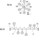
- the present invention six lever crank mechanisms are provided, and the phase intervals of the cam portions of the six turning radius adjusting mechanisms are 120 °, 120 °, ⁇ 60 from one of the rotation center axes of the input portion.
- the present invention can be applied to a continuously variable transmission set to °, 120 °, and 120 °.
- phase intervals of the cam portions of the six turning radius adjustment mechanisms are 180 °, 60 °, and 180 ° from one of the rotation center axes of the input portion. , 60 °, and 180 ° can be applied to a continuously variable transmission.
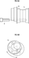
- FIG. 6A is an explanatory diagram illustrating the rotating unit of the first embodiment from the axial direction.
- 6B is a cross-sectional view taken along line BB in FIG. 6A.
- 7A and 7B are explanatory diagrams showing changes in the rotation radius (eccentricity) of the rotational radius adjusting mechanism of the first embodiment.
- FIG. 7A shows the maximum eccentricity
- FIG. 7B shows the middle eccentricity
- FIG. 7C shows the eccentricity. Is small
- FIG. 7D shows the case where the amount of eccentricity is “0”.
- 8A is an explanatory diagram showing an enlarged view of FIG. 7A
- FIG. 8B is an explanatory diagram showing an enlarged state similar to FIG. 7D.
- FIG. 9A is an explanatory view schematically showing a continuously variable transmission.
- FIG. 9B is an explanatory diagram showing the phase of the cam portion.
- FIG. 9C is an explanatory diagram showing the relationship between the inter-axis distances of the cam portions.
- FIG. 10A is an explanatory diagram showing a portion where the cam portions overlap when the phase difference between adjacent cam portions is 60 °.
- FIG. 10B is an explanatory diagram showing a portion where the cam portions overlap when the phase difference between adjacent cam portions is 120 °.
- FIG. 10C is an explanatory diagram showing a portion where the cam portions overlap when the phase difference between adjacent cam portions is 180 °.
- FIG. 11A is an explanatory diagram showing the phase of the cam portion of the second embodiment.
- FIG. 11B is an explanatory diagram illustrating the relationship between the inter-axis distances of the cam portions of the second embodiment.
- disassembles and shows the cam shaft of 2nd Embodiment. Explanatory drawing which shows the cam shaft of 2nd Embodiment.
- FIG. 14A is an explanatory view showing a state in which the cam portion adjacent to the double-sided female screw type cam portion of the second embodiment is connected by a bolt, and FIG. 14B shows the double-sided female screw type cam portion of the second embodiment from the axial direction.
- FIG. FIG. 15A is an explanatory diagram illustrating a state in which the phase difference between adjacent cam portions is large
- FIG. 15B is an explanatory diagram illustrating FIG. 15A from the axial direction
- FIG. 16A is an explanatory diagram illustrating a state in which the phase difference between adjacent cam portions is small
- FIG. 16B is an explanatory diagram illustrating FIG. 16A from the axial direction.
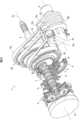
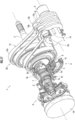
- the perspective view which partially cuts and shows the continuously variable transmission of 3rd Embodiment.
- Sectional drawing which shows the continuously variable transmission of 3rd Embodiment.
- Sectional drawing which expands and shows a part of FIG. Explanatory drawing which shows the conventional cam part as a comparative example for comparing with embodiment of this invention
- the four-bar linkage mechanism continuously variable transmission 1 of the first embodiment is rotated by receiving a rotational driving force from a driving source such as an engine (internal combustion engine) or an electric motor.
- a driving source such as an engine (internal combustion engine) or an electric motor.
- An input unit 2 that rotates about a central axis P1, an output shaft 3 that is arranged in parallel to the rotational central axis P1, and that transmits rotational power to driving wheels of a vehicle via a differential gear, a propeller shaft, etc. (not shown);
- six turning radius adjusting mechanisms 4 provided in the input unit 2.
- Each turning radius adjusting mechanism 4 includes a cam disk 5 as a cam part and a rotating disk 6 as a rotating part.
- the cam disks 5 have a disk shape, are eccentric from the rotation center axis P ⁇ b> 1, and are provided in each rotation radius adjustment mechanism 4 so as to form one set with respect to one rotation radius adjustment mechanism 4.
- the cam disk 5 is provided with a through hole 5a penetrating in the direction of the rotation center axis P1. Further, the cam disk 5 is provided with a notch hole 5b that opens in a direction opposite to the direction decentered with respect to the rotation center axis P1 and communicates the outer peripheral surface of the cam disk 5 with the through hole 5a.
- Each set of cam disks 5 is arranged so as to make a round in the circumferential direction of the input unit 2 with six sets of cam disks 5 with a phase difference of 60 degrees (see FIG. 9B).
- the six turning radius adjusting mechanisms 4 are defined as first to sixth turning radius adjusting mechanisms # 1 to # 6 in order from the side opposite to the engine, as shown in FIGS. 9A to 9C.
- each set of the cam disks 5 of the first to sixth turning radius adjusting mechanisms # 1 to # 6 is defined as a first to sixth cam disk pair C1 to C6 in order from the side opposite to the engine.
- the phases of the first cam disk pair C1 and the second cam disk pair C2 are shifted by 180 °.
- the phases of the second cam disk pair C2 and the third cam disk pair C3 are shifted by 60 ° counterclockwise in FIG. 9B.
- the phases of the third cam disk pair C3 and the fourth cam disk pair C4 are shifted by 180 °.
- the phases of the fourth cam disk pair C4 and the fifth cam disk pair C5 are shifted by 60 ° counterclockwise in FIG. 9B.
- the phases of the fifth cam disk pair C5 and the sixth cam disk pair are shifted by 180 °.
- cam disk pairs C1 to C6 are arranged at equal intervals of a predetermined interval X between the bearings 51a that support the camshaft 51 at the end.
- the cam disk 5 is formed integrally with the cam disk 5 of the adjacent turning radius adjusting mechanism 4 to constitute an integrated cam portion 5c.
- the integrated cam portion 5c may be formed by integral molding, or may be integrated by welding two cam portions.
- a pair of cam disks 5 constituting the first to sixth cam disk pairs C1 to C6 are fixed with bolts B (see FIG. 10). Thereby, the camshaft 51 is comprised.
- the camshaft 51 is formed in a hollow shape in which one end on the opposite side to the engine is opened by connecting the through holes 5a of the cam disk 5, and the cam disk 5 located at the other end on the engine side is connected to the input portion 2. And is formed integrally. That is, the cam disk 5 located at the end on the engine side is formed integrally with the input unit 2.
- integral molding may be used, or the cam disk 5 and the input part 2 may be integrated by welding.
- each set of cam disks 5 is externally fitted with a disk-shaped rotating disk 6 having a receiving hole 6a (see FIGS. 6A and 6B) for receiving the cam disk 5 in an eccentric state.
- the rotating disk 6 has a cam disk 5 center point P2 and a rotating disk 6 center point P3, a distance Ra between the rotation center axis P1 and the center point P2, and the center point P2 and the center point. It is eccentric with respect to the cam disk 5 so that the distance Rb of P3 is the same.
- an internal tooth 6 b is provided between the pair of cam disks 5.
- the pinion shaft 7 that is arranged concentrically with the rotation center axis P ⁇ b> 1 and has external teeth 7 a at locations corresponding to the internal teeth 6 b of the rotary disk 6 is arranged so as to be rotatable relative to the camshaft 51.
- the external teeth 7 a of the pinion shaft 7 mesh with the internal teeth 6 b of the rotating disk 6 through the cutout holes 5 b of the cam disk 5.
- the pinion shaft 7 of the first embodiment corresponds to the pinion of the present invention.
- a differential mechanism 8 is connected to the pinion shaft 7.
- the differential mechanism 8 is configured by a planetary gear mechanism, and includes a sun gear 9, a first ring gear 10 connected to the camshaft 51, a second ring gear 11 connected to the pinion shaft 7, a sun gear 9 and
- a carrier 13 is provided that supports a stepped pinion 12 including a large-diameter portion 12a that meshes with the first ring gear 10 and a small-diameter portion 12b that meshes with the second ring gear 11 so as to rotate and revolve freely.
- the rotating shaft 14a of the adjusting drive source 14 composed of an electric motor for the pinion shaft 7 is connected to the sun gear 9. If the rotational speed of the adjusting drive source 14 is the same as the rotational speed of the input unit 2, the sun gear 9 and the first ring gear 10 rotate at the same speed, and the sun gear 9, the first ring gear 10, and the second ring are rotated. The four elements of the gear 11 and the carrier 13 are locked so as not to rotate relative to each other, and the pinion shaft 7 connected to the second ring gear 11 rotates at the same speed as the input unit 2.
- the rotational speed of the adjusting drive source 14 is made slower than the rotational speed of the input unit 2
- the rotational speed of the sun gear 9 is Ns
- the rotational speed of the first ring gear 10 is NR1
- the number of rotations of the carrier 13 is (j ⁇ NR1 + Ns) / (j + 1) where j is the number of teeth of the first ring gear 10 / the number of teeth of the sun gear 9.
- the gear ratio between the sun gear 9 and the second ring gear 11 ((number of teeth of the second ring gear 11 / number of teeth of the sun gear 9) ⁇ (number of teeth of the large diameter portion 12a of the stepped pinion 12 / tooth of the small diameter portion 12b)
- the number of revolutions of the second ring gear 11 is ⁇ j (k + 1) NR1 + (k ⁇ j) Ns ⁇ / ⁇ k (j + 1) ⁇ where k is a number)).
- the rotating disk 6 is eccentric with respect to the cam disk 5 so that the distance Ra and the distance Rb are the same, and therefore the center point P3 of the rotating disk 6 is the same as the rotation center axis P1.
- the distance between the rotation center axis P1 and the center point P3, that is, the eccentric amount R1 can be set to “0” so as to be positioned on the axis.
- a connecting rod 15 having a large-diameter large-diameter annular portion 15a at one end and a small-diameter annular portion 15b having a smaller diameter than the large-diameter annular portion 15a at the other end is provided at the periphery of the rotating disk 6.
- a large-diameter annular portion 15a is rotatably fitted via a connecting rod bearing 16 made of a roller bearing.
- the connecting rod bearing 16 may comprise two ball bearings arranged in the axial direction as a set.
- the output shaft 3 is provided with six swing links 18 corresponding to the connecting rod 15 via a one-way clutch 17 as a one-way rotation prevention mechanism.
- the one-way clutch 17 as a one-way rotation prevention mechanism is provided between the swing link 18 and the output shaft 3, and swings on the output shaft 3 when attempting to rotate relative to the output shaft 3 on one side.
- the link 18 is fixed, and the swing link 18 is idled with respect to the output shaft 3 when attempting to rotate relative to the other side.
- the swing link 18 is swingable with respect to the output shaft 3 when the one-way clutch 17 is idle with respect to the output shaft 3.
- the swing link 18 is formed in an annular shape, and a swing end portion 18a connected to the small-diameter annular portion 15b of the connecting rod 15 is provided above the swing link 18.
- the swing end portion 18a is provided with a pair of projecting pieces 18b projecting so as to sandwich the small-diameter annular portion 15b in the axial direction.
- the pair of projecting pieces 18b are formed with through holes 18c corresponding to the inner diameter of the small-diameter annular portion 15b.
- a connecting pin 19 is inserted into the through hole 18c and the small diameter annular portion 15b. Thereby, the connecting rod 15 and the swing link 18 are connected.
- FIG. 7 shows the positional relationship between the pinion shaft 7 and the rotating disk 6 in a state where the eccentricity R1 of the turning radius adjusting mechanism 4 is changed.
- FIG. 7A shows a state in which the eccentric amount R1 is “maximum”, and the pinion shaft is such that the rotation center axis P1, the center point P2 of the cam disk 5, and the center point P3 of the rotation disk 6 are aligned. 7 and the rotating disk 6 are located. At this time, the gear ratio i is minimized.
- FIG. 7B shows a state in which the eccentric amount R1 is set to “medium” which is smaller than that in FIG. 7A
- FIG. 7C shows a state in which the eccentric amount R1 is set to be “small” which is further smaller than that in FIG.
- the gear ratio i is “medium” which is larger than the gear ratio i in FIG. 7A in FIG. 7B, and “large” which is larger than the gear ratio i in FIG. 7B in FIG. 7C
- FIG. 7D shows a state where the amount of eccentricity R1 is “0”, and the rotation center axis P1 and the center point P3 of the rotating disk 6 are located concentrically.
- the gear ratio i at this time is infinite ( ⁇ ).
- the radius of rotational motion on the input unit 2 side can be adjusted by changing the amount of eccentricity R1 by the rotational radius adjusting mechanism 4.
- the turning radius adjusting mechanism 4, the connecting rod 15, and the swing link 18 constitute a lever crank mechanism 20 (four-bar link mechanism). Then, the lever crank mechanism 20 converts the rotational motion of the input unit 2 into the swing motion of the swing link 18.
- the continuously variable transmission 1 of the first embodiment includes a total of six lever crank mechanisms 20.
- the swing link 18 Since the small-diameter annular portion 15b of the connecting rod 15 is connected to the swing link 18 provided on the output shaft 3 via the one-way clutch 17, the swing link 18 is pushed and pulled by the connecting rod 15 to swing. Then, the output shaft 3 rotates only when the swing link 18 rotates in either the pushing direction side or the pulling direction side, and the output shaft 3 rotates when the swing link 18 rotates in the other direction. Thus, the force of the swing motion of the swing link 18 is not transmitted to the swing link 18, and the swing link 18 is idled. Since each turning radius adjusting mechanism 4 is arranged with a phase changed every 60 degrees, the output shaft 3 is rotated in turn by each turning radius adjusting mechanism 4.
- the cam disks 5 of the turning radius adjusting mechanism 4 adjacent to each other in the axial direction of the rotation center axis P ⁇ b> 1 are configured integrally with each other so as to straddle the adjacent turning radius adjusting mechanism 4.
- the cam disk 5 of each turning radius adjusting mechanism 4 is composed of a plurality of members, that is, a cam disk pair constituted by a pair of cam disks 5.
- the adjacent cam disks 5 of the adjacent turning radius adjusting mechanisms 4 are integrally formed, and the cam disk 5 of one turning radius adjusting mechanism 4 is constituted by two members and can be divided. Yes.
- the cam disks 5 can be connected in each rotation radius adjusting mechanism 4 in which the adjacent areas of the adjacent cam disks 5 are large, and the adjacent rotation radii in which the overlapping area of the adjacent cam disks 5 is small. There is no need to connect the cam disk 5 between the adjusting mechanisms 4.
- FIG. 10 shows a change in the overlapping area of the cam disks 5 between the adjacent turning radius adjusting mechanisms 4.
- FIG. 10A shows the overlapping area portions in hatching when the phases of adjacent cam disks 5 differ by 60 °.
- FIG. 10B shows, in hatching, overlapping area portions when the phases of adjacent cam disks 5 differ by 120 °.
- FIG. 10C shows the overlapping area portion in the case where the phases of adjacent cam disks 5 are 180 ° different from each other by hatching.
- the accuracy of the internal teeth 6b is not lowered as in the case where the rotary disk 6 is divided in the radial direction.
- the cam disks 5 between the adjacent turning radius adjusting mechanisms 4 are configured as an integrally formed cam portion 5c. For this reason, even if the phase difference shown in FIG. 10C is 180 ° and the phase difference that cannot be connected by the bolt B can be set, the degree of freedom of setting between adjacent cam disks 5 can be improved. .
- the phase interval between the cam disk 5 serving as the cam portion and the adjacent cam disk 5 is 180 °, 60 °, 180 ° in order from the adjustment drive source 14 side as one of the rotation center axes. What was set to °, 60 °, and 180 ° was described.
- the phase interval between the cam portions of the cam portions of the present invention is not limited to this.
- the phase interval between adjacent cam portions is 120 °, 120 °, ⁇ 60 ° (300 °), 120 °, 120 ° from one of the rotation center axes. It may be set.
- the camshaft of the second embodiment it is possible to obtain an effect that the centrifugal forces generated in the respective cam portions cancel each other and vibrations associated with the rotation of the camshaft can be suppressed.
- FIG. 12 is an exploded perspective view showing the camshaft 51 of the second embodiment.
- FIG. 13 is an explanatory view showing the camshaft 51 of the second embodiment from the side.
- the camshaft 51 of the second embodiment has a portion where the phase difference of the cam disk 5 of the adjacent turning radius adjusting mechanism 4 is 60 °.
- it is an integral cam portion located between the third cam disk pair C3 and the fourth cam disk pair C4, and this corresponds to the double-sided female screw type cam part of the present invention.
- this integral cam portion is defined as a double-sided female screw type cam portion 5d.
- the first female threaded portion 71 is drilled in the double-sided female threaded cam portion 5d from one axial direction (engine side).
- the double-sided female screw type cam portion 5d is provided with a second female screw portion 72 from the other side in the axial direction (adjustment drive source side).
- the bolts are screwed from both ends of the camshaft 51 toward the double-sided female threaded cam portion 5d so that the adjacent integrated cam portions 5c are connected to each other. It is configured.
- the camshaft 51 can be configured by appropriately connecting the cam disks with the bolts B without reducing the rigidity of the camshaft 51.
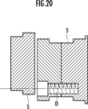
- FIG. 20 shows a comparative example in which a conventional camshaft 51 is not provided with an integral cam portion.
- each cam disk 5 is a separate body, so that it is understood that the problem of the space for arranging the heads of the bolts B does not occur.
- the input portion 2 ′ is constituted by a hollow shaft having an open end, and the through hole 5a is inserted so that the input portion 2 ′ can be inserted into the disc-shaped cam disk 5. May be drilled larger than that of the first embodiment, and the cam disk 5 may be splined to the outer peripheral surface of the input portion 2 ′ formed of a hollow shaft.
- a notch hole 2a ' is provided in the input portion 2' formed of a hollow shaft so as to correspond to the notch hole 5b of the cam disk 5 '. Then, the pinion shaft 7 inserted into the input portion 2 ′ meshes with the internal teeth 6 b of the rotating disk 6 through the notch hole 2 a ′ of the input portion 2 ′ and the notch hole 5 b of the cam disk 5 ′.
- the area where the cam portions of the adjacent turning radius adjusting mechanisms overlap when the phase difference in FIG. This corresponds to “a predetermined area set based on the strength of time”.
- the transmission is not limited to this.
- adjacent cam disks 5 between the second cam disk pair C2 and the third cam disk pair C3 having a phase difference of 60 °.
- the adjacent cam disks 5 between the fourth cam disk pair C4 and the fifth cam disk pair C5 may be connected by bolts as shown in FIG. 10A. This is because, when the phase difference is 60 °, the area where the cam disks overlap is not less than the predetermined area, but is not less than the predetermined area.
- the “predetermined area” of the present invention varies depending on the material, strength, size, etc. of the cam portion, and is set by obtaining in advance whether or not the strength required for the camshaft can be obtained through experiments. It is what is done.
- the one-way clutch 17 is used as the one-way rotation prevention mechanism.
- the one-way rotation prevention mechanism of the present invention is not limited to this, and the swing link 18 is connected to the output shaft 3. You may comprise with the two-way clutch (two-way clutch) comprised so that the rotation direction with respect to the output shaft 3 of the rocking
Abstract
Description
2 入力部(第1実施形態)
2’ 入力部(第3実施形態)
2a’ 切欠孔(第3実施形態)
3 出力軸
4 回転半径調節機構
5 カムディスク(第1実施形態のカム部)
5’ カムディスク(第3実施形態のカム部)
5a 貫通孔
5b 切欠孔
5c 一体型カム部
5d 両面雌ネジ型カム部(第2実施形態)
6 回転ディスク(回転部)
6a 受入孔(内周部)
6b 内歯
7 ピニオンシャフト(ピニオン)
7a 外歯
8 差動機構(遊星歯車機構)
9 サンギア
10 第1リングギア
11 第2リングギア
12 段付きピニオン
12a 大径部
12b 小径部
13 キャリア
14 調節用駆動源(電動機)
14a 回転軸
15 コネクティングロッド
15a 大径環状部
15b 小径環状部
16 コンロッド軸受
17 一方向クラッチ(一方向回転阻止機構)
18 揺動リンク
18a 揺動端部
18b 突片
18c 貫通孔
19 連結ピン
20 てこクランク機構(四節リンク機構)
51 カムシャフト
51a 軸受
71 第1雌ネジ部
72 第2雌ネジ部
P1 回転中心軸線
P2 カムディスクの中心点
P3 回転ディスクの中心点
Ra P1とP2の距離
Rb P2とP3の距離
R1 偏心量(P1とP3の距離)
θ1 回転半径調節機構の回転角度
θ2 揺動範囲
#1 第1回転半径調節機構
#2 第2回転半径調節機構
#3 第3回転半径調節機構
#4 第4回転半径調節機構
#5 第5回転半径調節機構
#6 第6回転半径調節機構
C1 第1カムディスク対
C2 第2カムディスク対
C3 第3カムディスク対
C4 第4カムディスク対
C5 第5カムディスク対
C6 第6カムディスク対 1 continuously
2 'input part (3rd Embodiment)
2a ′ cutout hole (third embodiment)
3
5 'cam disc (cam part of the third embodiment)
5a Through-
6 Rotating disc (rotating part)
6a Receiving hole (inner circumference)
6b
9
18
51
θ1 rotation angle theta 2 swing range of the rotational radius
Claims (8)
- 走行用駆動源からの駆動力が伝達される入力部と、
前記入力部の回転中心軸線と平行に配置された出力軸と、
前記出力軸に揺動自在に軸支される揺動リンクを有し、前記入力部の回転運動を前記揺動リンクの揺動運動に変換する複数のてこクランク機構と、
前記出力軸に対して一方側に相対回転しようとするときに前記出力軸に該揺動リンクを固定し、他方側に相対回転しようとするときに前記出力軸に対して該揺動リンクを空転させる一方向回転阻止機構とを備え、
前記てこクランク機構が、調節用駆動源と、該調節用駆動源の駆動力を用いて前記入力部の側の回転運動の半径を調節自在な回転半径調節機構と、該回転半径調節機構と前記揺動リンクとを連結するコネクティングロッドとを備える無段変速機であって、
前記回転半径調節機構は、
前記入力部の回転中心軸線に対して偏心した状態で前記入力部と一体的に回転するカム部と、
前記カム部に対して偏心した状態で回転自在な回転部と、
前記調節用駆動源の駆動力が伝達されるピニオンとを備え、
前記カム部は、複数部材で構成され、
軸方向に隣接する前記回転半径調節機構の前記カム部は、隣接する前記回転半径調節機構に跨るように互いに一体的に構成される一体型カム部であることを特徴とする無段変速機。 An input unit to which driving force from the driving source for traveling is transmitted;
An output shaft disposed parallel to the rotation center axis of the input unit;
A plurality of lever crank mechanisms having a swing link pivotally supported on the output shaft, and converting the rotational motion of the input portion into the swing motion of the swing link;
The swing link is fixed to the output shaft when attempting to rotate relative to the output shaft on one side, and the swing link is idled relative to the output shaft when attempting to rotate relative to the other side. A one-way rotation prevention mechanism
The lever crank mechanism includes an adjustment drive source, a rotation radius adjustment mechanism capable of adjusting a radius of rotational motion on the input unit side using a drive force of the adjustment drive source, the rotation radius adjustment mechanism, and the A continuously variable transmission comprising a connecting rod connecting the swing link;
The turning radius adjusting mechanism includes:
A cam portion that rotates integrally with the input portion in an eccentric state with respect to the rotation center axis of the input portion;
A rotating part rotatable in an eccentric state with respect to the cam part;
A pinion to which the driving force of the adjustment driving source is transmitted,
The cam portion is composed of a plurality of members.
2. The continuously variable transmission according to claim 1, wherein the cam portions of the rotating radius adjusting mechanism adjacent in the axial direction are integral cam portions configured integrally with each other so as to straddle the adjacent rotating radius adjusting mechanism. - 請求項1に記載の無段変速機であって、
前記一体型カム部は、隣接する前記回転半径調節機構のカム部の重なり合う面積がボルトによる連結時の強度に基いて設定される所定面積未満であることを特徴とする無段変速機。 The continuously variable transmission according to claim 1,
In the continuously variable transmission, the integral cam portion has an overlapping area of adjacent cam portions of the turning radius adjusting mechanism that is less than a predetermined area set based on a strength at the time of connection with a bolt. - 請求項1に記載の無段変速機であって、
前記一体型カム部には、雌ネジ部と、該雌ネジ部に螺合するボルトの雄ネジ部を挿通させる挿通孔とが設けられ、
隣接する前記一体型カム部同士は、前記雌ネジ部に螺合するボルトで連結され、
複数の前記一体型カム部のうち少なくとも1つは、軸方向一方側から前記ボルトが螺合される前記雌ネジ部と、軸方向他方側から前記ボルトが螺合される前記雌ネジ部とを備える両面雌ネジ型カム部であることを特徴とする無段変速機。 The continuously variable transmission according to claim 1,
The integrated cam portion is provided with a female screw portion and an insertion hole through which a male screw portion of a bolt screwed into the female screw portion is inserted.
The adjacent integrated cam portions are connected by bolts that are screwed into the female screw portion,
At least one of the plurality of integrated cam portions includes the female screw portion to which the bolt is screwed from one side in the axial direction and the female screw portion to which the bolt is screwed from the other side in the axial direction. A continuously variable transmission comprising a double-sided female screw cam portion. - 請求項3に記載の無段変速機であって、
前記両面雌ネジ型カム部は、隣接する前記回転半径調節機構のカム部の重なり合う面積が前記ボルトによる連結時の強度に基いて設定される所定面積以上であることを特徴とする無段変速機。 The continuously variable transmission according to claim 3,
In the continuously variable transmission, the double-sided female threaded cam portion has an overlapping area of adjacent cam portions of the turning radius adjusting mechanism that is equal to or larger than a predetermined area set based on a strength when connected by the bolt. . - 請求項4に記載の無段変速機であって、
前記てこクランク機構を6つ備え、
6つの前記回転半径調節機構のカム部の位相の間隔は、前記入力部の回転中心軸線の一方から120°、120°、-60°、120°、120°に設定されることを特徴とする無段変速機。 The continuously variable transmission according to claim 4,
Six lever crank mechanisms are provided,
The intervals of the phases of the cam portions of the six turning radius adjusting mechanisms are set to 120 °, 120 °, −60 °, 120 °, and 120 ° from one of the rotation center axes of the input portions. Continuously variable transmission. - 請求項4に記載の無段変速機であって、
前記てこクランク機構を6つ備え、
6つの前記回転半径調節機構のカム部の位相の間隔は、前記入力部の回転中心軸線の一方から180°、60°、180°、60°、180°に設定されることを特徴とする無段変速機。 The continuously variable transmission according to claim 4,
Six lever crank mechanisms are provided,
The phase intervals of the cam portions of the six turning radius adjusting mechanisms are set to 180 °, 60 °, 180 °, 60 °, and 180 ° from one of the rotation center axes of the input portions. Step transmission. - 請求項1に記載の無段変速機であって、
前記てこクランク機構を6つ備え、
6つの前記回転半径調節機構のカム部の位相の間隔は、前記入力部の回転中心軸線の一方から120°、120°、-60°、120°、120°に設定されることを特徴とする無段変速機。 The continuously variable transmission according to claim 1,
Six lever crank mechanisms are provided,
The intervals of the phases of the cam portions of the six turning radius adjusting mechanisms are set to 120 °, 120 °, −60 °, 120 °, and 120 ° from one of the rotation center axes of the input portions. Continuously variable transmission. - 請求項1に記載の無段変速機であって、
前記てこクランク機構を6つ備え、
6つの前記回転半径調節機構のカム部の位相の間隔は、前記入力部の回転中心軸線の一方から180°、60°、180°、60°、180°に設定されることを特徴とする無段変速機。 The continuously variable transmission according to claim 1,
Six lever crank mechanisms are provided,
The phase intervals of the cam portions of the six turning radius adjusting mechanisms are set to 180 °, 60 °, 180 °, 60 °, and 180 ° from one of the rotation center axes of the input portions. Step transmission.
Priority Applications (4)
| Application Number | Priority Date | Filing Date | Title |
|---|---|---|---|
| US14/646,237 US9441716B2 (en) | 2012-12-27 | 2013-12-04 | Stepless transmission |
| DE112013006276.3T DE112013006276T5 (en) | 2012-12-27 | 2013-12-04 | Stepless transmission |
| JP2014554275A JP5908610B2 (en) | 2012-12-27 | 2013-12-04 | Continuously variable transmission |
| CN201380061467.0A CN105723120B (en) | 2012-12-27 | 2013-12-04 | Buncher |
Applications Claiming Priority (2)
| Application Number | Priority Date | Filing Date | Title |
|---|---|---|---|
| JP2012286029 | 2012-12-27 | ||
| JP2012-286029 | 2012-12-27 |
Publications (1)
| Publication Number | Publication Date |
|---|---|
| WO2014103636A1 true WO2014103636A1 (en) | 2014-07-03 |
Family
ID=51020730
Family Applications (1)
| Application Number | Title | Priority Date | Filing Date |
|---|---|---|---|
| PCT/JP2013/082556 WO2014103636A1 (en) | 2012-12-27 | 2013-12-04 | Continuously variable transmission |
Country Status (5)
| Country | Link |
|---|---|
| US (1) | US9441716B2 (en) |
| JP (1) | JP5908610B2 (en) |
| CN (1) | CN105723120B (en) |
| DE (1) | DE112013006276T5 (en) |
| WO (1) | WO2014103636A1 (en) |
Cited By (1)
| Publication number | Priority date | Publication date | Assignee | Title |
|---|---|---|---|---|
| CN107515107A (en) * | 2017-06-30 | 2017-12-26 | 中船动力研究院有限公司 | Air bleeding valve testing stand dynamic power machine formula cylinder pressure analogue means |
Families Citing this family (2)
| Publication number | Priority date | Publication date | Assignee | Title |
|---|---|---|---|---|
| CN106555867B (en) * | 2017-01-20 | 2018-09-11 | 蔡明� | A kind of gearbox |
| EP3735544B1 (en) * | 2018-02-27 | 2021-04-14 | FAHRNI, Dieter Gerhard | Continuously variable transmission and method for operating a continuously variable transmission |
Citations (12)
| Publication number | Priority date | Publication date | Assignee | Title |
|---|---|---|---|---|
| GB132628A (en) * | 1900-01-01 | |||
| US1343254A (en) * | 1920-06-15 | Gearless variable-speed transmission | ||
| US1945702A (en) * | 1930-02-10 | 1934-02-06 | Pitter Trnst | Variable speed transmission |
| JPH058336Y2 (en) * | 1986-07-09 | 1993-03-02 | ||
| JP2005502543A (en) * | 2001-09-26 | 2005-01-27 | ルーク ラメレン ウント クツプルングスバウ ベタイリグングス コマンディートゲゼルシャフト | Drive device |
| DE102009039993A1 (en) * | 2008-09-11 | 2010-04-15 | Luk Lamellen Und Kupplungsbau Beteiligungs Kg | Transmission arrangement for crank-continuously variable transmission of motor vehicle, has drive shaft comprising independent and different individual parts, which are connected together in torque proof, centrical and axial manner |
| JP2011518290A (en) * | 2008-04-15 | 2011-06-23 | シェフラー テクノロジーズ ゲゼルシャフト ミット ベシュレンクテル ハフツング ウント コンパニー コマンディートゲゼルシャフト | Device for adjusting the amount of eccentricity for a crank CVT transmission |
| JP2011528776A (en) * | 2008-07-21 | 2011-11-24 | シェフラー テクノロジーズ ゲゼルシャフト ミット ベシュレンクテル ハフツング ウント コンパニー コマンディートゲゼルシャフト | Adjusting device for electrical adjustment of crank CVT |
| JP2012506003A (en) * | 2008-10-16 | 2012-03-08 | シェフラー テクノロジーズ ゲゼルシャフト ミット ベシュレンクテル ハフツング ウント コンパニー コマンディートゲゼルシャフト | Drive shaft assembly for automotive transmission |
| JP2012051539A (en) * | 2010-09-03 | 2012-03-15 | Honda Motor Co Ltd | Automobile driving system, and control method thereof |
| JP2012141048A (en) * | 2011-01-06 | 2012-07-26 | Honda Motor Co Ltd | Continuously variable transmission, and automobile driving system |
| JP2012251618A (en) * | 2011-06-03 | 2012-12-20 | Honda Motor Co Ltd | Power transmission device for vehicle |
Family Cites Families (3)
| Publication number | Priority date | Publication date | Assignee | Title |
|---|---|---|---|---|
| US2116624A (en) * | 1936-12-03 | 1938-05-10 | Walter A Garratt | Adjusting mechanism for transmissions |
| JP4115166B2 (en) * | 2002-05-31 | 2008-07-09 | 本田技研工業株式会社 | Bicycle with continuously variable transmission |
| JP2005351452A (en) * | 2004-06-14 | 2005-12-22 | Honda Motor Co Ltd | Built-up crankshaft |
-
2013
- 2013-12-04 JP JP2014554275A patent/JP5908610B2/en active Active
- 2013-12-04 DE DE112013006276.3T patent/DE112013006276T5/en not_active Withdrawn
- 2013-12-04 US US14/646,237 patent/US9441716B2/en not_active Expired - Fee Related
- 2013-12-04 CN CN201380061467.0A patent/CN105723120B/en active Active
- 2013-12-04 WO PCT/JP2013/082556 patent/WO2014103636A1/en active Application Filing
Patent Citations (12)
| Publication number | Priority date | Publication date | Assignee | Title |
|---|---|---|---|---|
| GB132628A (en) * | 1900-01-01 | |||
| US1343254A (en) * | 1920-06-15 | Gearless variable-speed transmission | ||
| US1945702A (en) * | 1930-02-10 | 1934-02-06 | Pitter Trnst | Variable speed transmission |
| JPH058336Y2 (en) * | 1986-07-09 | 1993-03-02 | ||
| JP2005502543A (en) * | 2001-09-26 | 2005-01-27 | ルーク ラメレン ウント クツプルングスバウ ベタイリグングス コマンディートゲゼルシャフト | Drive device |
| JP2011518290A (en) * | 2008-04-15 | 2011-06-23 | シェフラー テクノロジーズ ゲゼルシャフト ミット ベシュレンクテル ハフツング ウント コンパニー コマンディートゲゼルシャフト | Device for adjusting the amount of eccentricity for a crank CVT transmission |
| JP2011528776A (en) * | 2008-07-21 | 2011-11-24 | シェフラー テクノロジーズ ゲゼルシャフト ミット ベシュレンクテル ハフツング ウント コンパニー コマンディートゲゼルシャフト | Adjusting device for electrical adjustment of crank CVT |
| DE102009039993A1 (en) * | 2008-09-11 | 2010-04-15 | Luk Lamellen Und Kupplungsbau Beteiligungs Kg | Transmission arrangement for crank-continuously variable transmission of motor vehicle, has drive shaft comprising independent and different individual parts, which are connected together in torque proof, centrical and axial manner |
| JP2012506003A (en) * | 2008-10-16 | 2012-03-08 | シェフラー テクノロジーズ ゲゼルシャフト ミット ベシュレンクテル ハフツング ウント コンパニー コマンディートゲゼルシャフト | Drive shaft assembly for automotive transmission |
| JP2012051539A (en) * | 2010-09-03 | 2012-03-15 | Honda Motor Co Ltd | Automobile driving system, and control method thereof |
| JP2012141048A (en) * | 2011-01-06 | 2012-07-26 | Honda Motor Co Ltd | Continuously variable transmission, and automobile driving system |
| JP2012251618A (en) * | 2011-06-03 | 2012-12-20 | Honda Motor Co Ltd | Power transmission device for vehicle |
Cited By (1)
| Publication number | Priority date | Publication date | Assignee | Title |
|---|---|---|---|---|
| CN107515107A (en) * | 2017-06-30 | 2017-12-26 | 中船动力研究院有限公司 | Air bleeding valve testing stand dynamic power machine formula cylinder pressure analogue means |
Also Published As
| Publication number | Publication date |
|---|---|
| CN105723120A (en) | 2016-06-29 |
| JP5908610B2 (en) | 2016-04-27 |
| CN105723120B (en) | 2018-01-23 |
| US9441716B2 (en) | 2016-09-13 |
| DE112013006276T5 (en) | 2015-10-01 |
| JPWO2014103636A1 (en) | 2017-01-12 |
| US20150292605A1 (en) | 2015-10-15 |
Similar Documents
| Publication | Publication Date | Title |
|---|---|---|
| US9121483B2 (en) | Four-joint link type continuously variable transmission | |
| JP5702249B2 (en) | Four-bar linkage type continuously variable transmission | |
| JP5822594B2 (en) | Four-bar linkage type continuously variable transmission | |
| JP5825916B2 (en) | Four-bar linkage type continuously variable transmission | |
| WO2017094796A1 (en) | Transmission device and differential device | |
| JP5908610B2 (en) | Continuously variable transmission | |
| JP5694857B2 (en) | Lubricating oil supply structure for continuously variable transmission | |
| JP5882478B2 (en) | Continuously variable transmission | |
| JP2012251609A (en) | Continuously variable transmission | |
| JP6067593B2 (en) | Continuously variable transmission | |
| JP6096565B2 (en) | Continuously variable transmission | |
| JP6014503B2 (en) | Continuously variable transmission | |
| JP6087320B2 (en) | Continuously variable transmission | |
| JP6100609B2 (en) | Continuously variable transmission | |
| JP6132689B2 (en) | Continuously variable transmission | |
| JP6130223B2 (en) | Continuously variable transmission | |
| JP5807040B2 (en) | Continuously variable transmission | |
| JP6002608B2 (en) | Continuously variable transmission | |
| JP5982262B2 (en) | Continuously variable transmission | |
| JP5896868B2 (en) | Four-bar linkage type continuously variable transmission | |
| JP6132804B2 (en) | Driving force transmission device | |
| JP6029568B2 (en) | Continuously variable transmission | |
| JP2014228102A (en) | Continuously variable transmission | |
| WO2015159462A1 (en) | Drive force transmission device | |
| WO2014156334A1 (en) | Stepless transmission |
Legal Events
| Date | Code | Title | Description |
|---|---|---|---|
| 121 | Ep: the epo has been informed by wipo that ep was designated in this application |
Ref document number: 13867798 Country of ref document: EP Kind code of ref document: A1 |
|
| DPE1 | Request for preliminary examination filed after expiration of 19th month from priority date (pct application filed from 20040101) | ||
| ENP | Entry into the national phase |
Ref document number: 2014554275 Country of ref document: JP Kind code of ref document: A |
|
| WWE | Wipo information: entry into national phase |
Ref document number: 14646237 Country of ref document: US |
|
| WWE | Wipo information: entry into national phase |
Ref document number: 1120130062763 Country of ref document: DE Ref document number: 112013006276 Country of ref document: DE |
|
| 122 | Ep: pct application non-entry in european phase |
Ref document number: 13867798 Country of ref document: EP Kind code of ref document: A1 |