WO2014103501A1 - 画像処理装置、画像処理方法、画像処理プログラム及びそのプログラムを格納した記録媒体 - Google Patents
画像処理装置、画像処理方法、画像処理プログラム及びそのプログラムを格納した記録媒体 Download PDFInfo
- Publication number
- WO2014103501A1 WO2014103501A1 PCT/JP2013/079447 JP2013079447W WO2014103501A1 WO 2014103501 A1 WO2014103501 A1 WO 2014103501A1 JP 2013079447 W JP2013079447 W JP 2013079447W WO 2014103501 A1 WO2014103501 A1 WO 2014103501A1
- Authority
- WO
- WIPO (PCT)
- Prior art keywords
- image
- images
- image processing
- reference image
- positional deviation
- Prior art date
- Legal status (The legal status is an assumption and is not a legal conclusion. Google has not performed a legal analysis and makes no representation as to the accuracy of the status listed.)
- Ceased
Links
Images






Classifications
-
- A—HUMAN NECESSITIES
- A61—MEDICAL OR VETERINARY SCIENCE; HYGIENE
- A61B—DIAGNOSIS; SURGERY; IDENTIFICATION
- A61B3/00—Apparatus for testing the eyes; Instruments for examining the eyes
- A61B3/10—Objective types, i.e. instruments for examining the eyes independent of the patients' perceptions or reactions
- A61B3/102—Objective types, i.e. instruments for examining the eyes independent of the patients' perceptions or reactions for optical coherence tomography [OCT]
Definitions
- the present invention stores an image processing apparatus, an image processing method, an image processing program, and a program for processing a medical image captured by a tomographic imaging apparatus or the like to generate a high-quality image suitable for an image for interpretation.
- the present invention relates to a recording medium.
- OCT Optical Coherence Tomography
- OCT Optical Coherence Tomography
- the obtained tomographic image is captured at a speed of, for example, 40 images / second, and 100 images or more are acquired by one inspection (imaging at a part of the retina).
- a completed image group is created.
- a slight (very small) lesion or the like may appear in only a part of the captured images, for example, about 10 out of 100 images.
- Patent Document 1 the latest one of the past images of the same patient or a thumbnail is displayed and one of them is read as a reference image, and the current image is displayed at the same time. A configuration for observing is disclosed.
- the CT image is added by making the weighting coefficient of the image at the observation location larger than the weighting coefficients at the other locations in the CT image, and the addition is created by emphasizing the observation location. It is disclosed.
- Patent Document 3 discloses a technique for detecting a feature portion in a two-dimensional tomographic image and correcting a positional shift between a plurality of two-dimensional tomograms using the two-dimensional tomographic image from which the feature portion is detected as a reference tomographic image. Yes.
- Patent Document 4 discloses a technique for generating a tomographic image with less noise by adding and averaging the entire taken two-dimensional tomographic image.
- Patent Document 5 after positioning another two-dimensional tomographic image with respect to a reference two-dimensional tomographic image, the degree of similarity between the tomographic images is determined, and a two-dimensional tomographic image having a high degree of similarity is extracted.
- a technique for performing a superposition process and generating a high-quality tomographic image in which the positional deviation is corrected is disclosed.
- Patent Document 6 one image is taken out from a plurality of tomographic images as a reference image, a predetermined number of tomographic images are selected, and the reference image and the selected image are divided into a plurality of regions of the same number, respectively.
- a technique for correcting a positional shift between images for each divided region is disclosed.
- Non-Patent Document 1 discloses a technique of aligning individual A scans from corresponding retinal regions of a series of B scans, creating corrected B scans, and averaging them.
- Patent Documents 1 to 3 are used when making a diagnosis by comparing an image cited as a reference image with a captured image, and remove images that contain noise or cause misalignment. It does not create high-quality images for interpretation.
- Patent Document 4 since an image in which noise is reduced is generated by averaging a plurality of images, when the plurality of images includes a lot of noise or includes a large number of misaligned images. Cannot produce high quality images.
- Non-Patent Document 1 has a problem in that since the correlation is observed based on individual A-scan signal differences, the region for alignment is narrow, and the B-scan misalignment cannot be accurately corrected. .
- the present invention has been made in view of such a point, and image processing that can generate a high-quality image with less noise and suitable for interpretation of a photographing object from images obtained by photographing a plurality of the same portions. It is an object to provide an apparatus, an image processing method, an image processing program, and a recording medium storing the program.
- the present invention (Claims 1 and 6) An image processing apparatus and method for detecting a positional deviation from a reference image by comparing a plurality of images obtained by photographing the same part with a reference image, and generating an image in which the positional deviation is corrected, Selecting all of the plurality of images or a predetermined number of images thereof, Dividing the selected image into a plurality of regions; Searching for an image corresponding to the image of the divided area from the reference image for each divided area, and adding the image of the divided area to the searched image; Generating an image in which the misalignment is corrected by averaging the added images; It is characterized by.
- the present invention (Claims 2 and 7) An image processing apparatus and method for detecting a positional deviation from a reference image by comparing a plurality of images obtained by photographing the same part with a reference image, and generating an image in which the positional deviation is corrected, Selecting all of the plurality of images or a predetermined number of images thereof, Dividing the reference image into a plurality of regions; For each divided area, searching for an image corresponding to the image of the divided area from the selected image, and adding the searched image to the image of the divided area; Generating an image in which the misalignment is corrected by averaging the added images; It is characterized by.
- the present invention (claims 8 and 18) Selecting or creating a reference image from multiple images of the same location, Calculating a similarity between the selected or created reference image and another image; Selecting images whose calculated similarity satisfies the set value; Generating an image for interpretation by averaging the selected images; It is characterized by.
- one or a plurality of images are selected in order to determine a reference image from a plurality of images (for example, 100 images) taken at the same location.
- a reference image For example, 100 images
- the selected images are aligned and added and averaged to create a reference image.
- the image to be selected is preferably an image in which a region of interest or a feature portion is captured in the image.
- the image is a tomographic image of the retina of the eye to be examined, the image in which the lesion is captured or the retina
- An image having an average epithelial position is selected as an image for defining a reference image.
- the selected image is divided into a plurality of areas, and for each divided area, it is searched which part of the reference image corresponds to the image of the divided area.
- the image of the divided area of the selected image is added to the image portion of the searched reference image, and an image in which the positional deviation is corrected is generated.
- the reference image is divided into a plurality of areas, and for each divided area, it is searched which part of the selected image corresponds to the image of the divided area.
- the searched image portion of the selected image is added to the image of the divided region of the reference image, and an image in which the positional deviation is corrected is generated.
- an evaluation area larger than the divided area including the image of the divided area is set. Using this evaluation area, an image corresponding to the image in the divided area is searched. In addition, a search area larger than the evaluation area is set, and an image corresponding to the image of the divided area is searched in the search area.
- the selected image or the reference image is divided into a plurality of regions, and for each divided region, an image corresponding to the image of the divided region is the reference image or the selected image. Since the search is performed from the inside, it is possible to detect the amount of displacement by performing a search in a wide range. Therefore, even if there is a significant movement of the subject, it is possible to generate an image in which the positional deviation is corrected by detecting the positional deviation satisfactorily.
- a reference image can be selected or created, an image in which a region of interest (for example, a lesion) is photographed is selected as a reference image, or a region of interest is photographed.
- a region of interest for example, a lesion
- a region of interest is photographed.
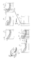
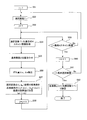
- FIG. 1 is a block diagram illustrating an entire system that acquires a tomographic image of a fundus of a subject's eye and performs image processing. It is explanatory drawing which showed the state which scans a fundus with signal light. It is explanatory drawing which showed the state which acquires the tomographic image of several sheets. It is the flowchart figure which showed the flow of the image processing of this invention. It is explanatory drawing explaining the process which produces an average image from a some tomographic image. It is explanatory drawing explaining the process which produces a reference
- the image to be processed will be described by taking a tomographic image of the fundus of the eye to be examined as an example, but the image to be processed in the present invention is not limited to the tomographic image of the fundus oculi, The same applies to images.
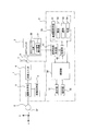
- FIG. 1 is a block diagram showing the entire system for acquiring and processing a tomographic image of the fundus of the eye to be examined.
- Reference numeral 1 denotes a fundus camera unit 1 that observes and images the fundus (retina) Ef of the eye E, and includes an illumination optical system 4, a photographing optical system 5, and a scanning unit 6.
- the illumination optical system 4 includes an observation light source such as a halogen lamp and a photographing light source such as a xenon lamp, and light from these light sources is guided to the fundus oculi Ef via the illumination optical system to illuminate the fundus.
- the photographing optical system 5 includes an optical system such as an objective lens and a photographing lens, and an imaging device such as a CCD.
- the photographing optical system 5 guides photographing light reflected by the fundus oculi Ef to the imaging device along the photographing optical path, and photographs an image of the fundus oculi Ef. .
- the imaging optical system 5 guides signal light from the OCT unit 2 reflected by the fundus oculi Ef, which will be described later, to the OCT unit 2.
- the scanning unit 6 is a mechanism including a galvano mirror for scanning the signal light from the OCT unit 2 in the X direction and the Y direction in FIG.
- the fundus camera unit 1 is optically connected to an OCT unit 2 that captures a tomographic image of the fundus oculi Ef via a connector 7 and a connection line 8.
- the OCT unit 2 is, for example, a known one that operates in a time domain method or a Fourier domain method, and has a low coherence light source 20 that emits light having a wavelength of 700 nm to 1100 nm and a temporal coherence length of about several ⁇ m to several tens of ⁇ m. .
- the light from the low-coherence light source 20 is divided into reference light and signal light, and the reference light follows the reference light path and is reflected by the reference mirror.
- the signal light is guided to the fundus camera unit 1 through the connection line 7 and the connector 8, and is scanned in the X and Y directions on the fundus oculi Ef by the scanning unit 6.
- the signal light reflected by the fundus oculi Ef and returning to the OCT unit 2 is superimposed on the reference light reflected by the reference mirror to generate interference light.
- the interference light is split in the OCT signal detection device 21 to generate an OCT signal indicating information in the depth direction (Z direction) of the fundus.
- the image processing apparatus 3 is configured by, for example, a microcomputer built in the fundus camera unit 1 or a personal computer connected to the fundus camera unit 1.
- the image processing apparatus 3 includes a control unit 30 including a CPU, a RAM, a ROM, and the like.
- the control unit 30 controls the entire image processing by executing an image processing program.
- the display unit 31 is configured by a display device such as an LCD, for example, and displays accompanying information such as an image generated or processed by the image processing device 3 and information on the subject.
- the operation unit 32 includes, for example, a mouse, a keyboard, an operation panel, and the like, and is used by an operator to give an instruction to the image processing apparatus 3 and the like.
- the tomographic image forming unit 41 is realized by a dedicated electronic circuit that executes a known analysis method such as a Fourier domain method (spectral domain method), or an image processing program that is executed by the above-described CPU. Based on the detected OCT signal, a tomographic image of the fundus oculi Ef is formed.
- the tomographic image formed by the tomographic image forming unit 41 is stored in a storage unit 42 configured by, for example, a semiconductor memory or a hard disk device.
- the storage unit 42 further stores the above-described image processing program and the like.
- the image processing unit 50 includes a reference image creation unit 51, a calculation unit 52, a selection unit 53, and a generation unit 54.
- the reference image creation unit 51 selects or creates a reference image from a plurality of photographed tomographic images
- the calculating means 52 calculates the similarity or positional deviation amount between the reference image and another image.
- the sorting unit 53 discriminates or sorts images in which the calculated similarity or displacement amount satisfies a set value, and the generation unit 54 adds and averages the discriminated or sorted images to generate a reading image.
- Each means or each image processing in the image processing unit 50 is realized by using a dedicated electronic circuit or by executing an image processing program.
- This image processing is performed by the control unit 30 reading and executing the image processing program stored in the storage unit 42.
- step S1 the fundus of the eye to be examined is photographed.
- the low coherence light source 20 is turned on, the signal light from the OCT unit 2 is swept in the X and Y directions by the scanning unit 6, and the fundus oculi Ef Scan.
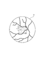
- This state is shown in FIG. 2, and the region R where the macular portion of the retina is present is scanned by n scanning lines y 1 , y 2 ,..., Y n in the direction parallel to the X axis. Is done.
- the signal light reflected by the fundus oculi Ef is superimposed on the reference light reflected by the reference mirror in the OCT unit 2.
- interference light is generated and an OCT signal is generated from the OCT signal detector 21.
- the tomographic image forming unit 41 generates a tomographic image of the fundus oculi Ef by Fourier transforming the OCT signal.
- the tomographic image generated by the tomographic image forming unit 41 is stored in the storage unit 42.
- slice scanning returns to the scanning by the scanning lines y 1 after the end of scanning by the scanning lines y n, repeating this.
- the galvanometer mirror of the scanning unit 6 that sweeps signal light in the y direction is fixed and the signal light is swept in the x direction.
- the galvanometer mirror scans the signal light to the end in the x direction, it returns to the start end, starts scanning again in the same x direction, and repeats this.
- processing of tomographic images obtained by single scanning is performed, but each tomographic image performed by slice scanning is a set of single scanning tomographic images at different scanning lines.
- the same processing can be performed by applying the processing of the obtained tomographic image to the tomographic image obtained by each slice scan.
- the stored tomographic images at the same location may be misaligned in the xz direction, and the quality of the constructed three-dimensional tomographic image deteriorates.
- a tomographic image is generated.
- step S2 from the storage unit 42 the N images T i as shown in FIG. 5a, to create an average image T A.
- Average image T A for example, to create an average value of pixel values for each pixel, a median, or by the most frequent value.
- the average image T A is not used all N images, select an image of a predetermined number of them, it is also possible to create an average image using the selected picture.
- the image selected for creating the average image is preferably an image in which a lesion is photographed or an image in which the position of the retinal epithelium is within a predetermined range.
- the correlation coefficient shown in Equation 1 can be used as the evaluation function indicating the similarity.
- T (k) is a set of pixel values (number of pixels n), and T (upper horizontal line) is an average of the pixel values.
- the degree of similarity between each image T i is the respective image translation, rotation, and scaling to be performed by obtaining a correlation coefficient by performing the alignment of the average image T A, perform the alignment Instead, a correlation coefficient may be obtained.
- the similarity can be calculated not by using a correlation coefficient but by using a difference (a positional deviation amount) between corresponding pixel values of each image T i and the average image T A.
- the correlation coefficient or the positional deviation amount may be obtained for the entire image, or may be obtained for a partial region (for example, a region having a lesioned part or a characteristic part).
- step S4 the image for which the maximum similarity is calculated is set as a reference image.
- the reference image generated is shown at T R in Fig. 5b.
- the reference image T R is the average image T A instead of similarity maximum image with an average image T A itself may be used as the reference image T R a, or similarity greater than a predetermined threshold value in step S3 It is also possible to extract a plurality of images having and to use the addition average image as a reference image.
- the operation unit 32 may be able to select whether to create a reference image based on an average image or to create a reference image by designating an image by an operator.
- the reference image T R is selected or created, stores it in the storage unit 42, as shown in FIG. 5b, it determines the feature region C of the reference image T R (step S5).
- the feature region C a region of the retinal layer or a region having a lesion in which the total luminance value is large, the contrast of luminance values (maximum value, minimum value) is large, or the total value of edge strength is large is selected. .
- This state is illustrated in FIG.
- Positional shift amount of each image x, x the similarity between the feature region C in the z-direction is moved reference image T R is maximized, by obtaining the amount of movement of the z-direction, also the similarity is a number 1 Calculate by obtaining the correlation coefficient.
- the processing of step S6 may calculate the positional deviation amount and the similarity based on the entire image instead of calculating the positional deviation amount and the similarity degree in the feature region C.
- step S7 a plurality of images (M, M is 30 for example) for which the degree of similarity satisfying the set value is calculated is selected.
- the set value is used as a similarity threshold, and an image having a similarity exceeding a predetermined similarity threshold is discriminated or selected by the selection means 53.
- Each selected image is stored in the storage unit 42.
- the similarity threshold is decreased so that M is close to 30.
- FIG. 6 illustrates the process performed in step S7.
- an image to select rather than similarity may be an image before and after a predetermined time period of time the reference image T R is obtained. For example, if the reference image T R is obtained at time t R, may be screened images in t (R + k) from the time t (R-k).
- a correlation coefficient as shown in Equation 1 can be used.
- the A scan line A i is set in the x direction as a whole, the number of the A scan lines A i may be limited to a part of the area, for example, the characteristic area C.
- the A scan line is a line extending in the z direction.
- the A scan line is a rectangular (strip-shaped) area having a width in the x direction with the line as the center. Based on the area, the similarity and the amount of displacement are determined. It can also be calculated.
- the image to be corrected and added in step S10 may be limited to an image in which the similarity or positional deviation amount for each local area with the reference image satisfies a predetermined set value. For example, correction and addition are performed in step S10 on an image in which the similarity for each local region is larger than a predetermined similarity threshold value, or an image in which the positional displacement amount for each local region is smaller than a predetermined positional displacement amount threshold value. Yes, and other images can be added. If the minimum added number cannot be obtained due to excessive limitation, the number of added sheets can be increased by decreasing the similarity threshold and increasing the positional deviation amount threshold.
- a reference image is selected or created (steps S2 to S4), and an image having a large degree of positional deviation based on fixation eye movement is selected by selecting an image having a high similarity to the reference image (step S7). Is removed and corrected, the misregistration amount for each A scan line is corrected and added (step S10), and finally one image is generated.
- a quality interpretation image can be generated.
- the image reference image of each A-scan line It is possible to correct the positional deviation of each image by averaging the obtained images. An example of this is shown in FIGS.
- FIG. 11 has the same configuration as that of FIG. 1 except for the image processing unit 60, and therefore, the description of the same or similar configuration as that of FIG. 1 is omitted.
- the image processing unit 60 includes a reference image creation unit 61, an image selection unit 62, an image division unit 63, an area setting unit 64, a positional deviation amount detection unit 65, and an addition average unit 66. Similar to the reference image creation means 51, the reference image creation means 61 selects or creates a reference image from a plurality of tomographic images taken at the same location. The image selection means 62 selects all or a predetermined number of images from a plurality of images taken at the same location. The image dividing unit 63 divides the tomographic image selected by the image selecting unit 62 into a plurality of regions, and the region setting unit 64 sets an evaluation region A in the selected image as will be described later, and searches in the reference image. Region B is set.
- the positional deviation amount detecting means 65 searches the reference image for an image corresponding to the image of the divided area, and within the reference image corresponding to the image of the divided area and the image. The amount of positional deviation from the image is detected.
- the addition averaging means 66 generates an image in which the positional deviation is corrected by adding and averaging the image of the divided area with the corresponding image in the reference image for each divided area based on the detected positional deviation amount.
- Each means or each image processing in the image processing unit 60 is realized by using a dedicated electronic circuit or by executing an image processing program.
- the selected image T i is the similarity between the reference image T R of a number of images captured from the same position is large M images are selected.
- each selected image Ti is divided by the image dividing means 63 into n regions along the A scan line, the x direction being the width of the A scan line (1 pixel) and the z direction being the length of k pixels.
- Positional deviation amount detecting means 65 for each of the n pieces of divided regions, searched from the reference image T R as a reference of the corresponding image position shift correction to the image of the divided region, and an image of the found The amount of positional deviation from the image of the divided area is detected.
- An image of a 1 ⁇ k pixel divided region is hereinafter referred to as an A scan image.
- the detection of the amount of displacement will be described with reference to the flowchart of FIG.
- step S54 the j-th A-scan image S j of the selected image T i is acquired.
- the division of the selected image T i and the j-th A-scan image S j are shown in the lower center of FIG.
- the selected image T i has a predetermined pixel added to the left and right in the x direction around the jth A-scan image S j (width 1 pixel), for example, 21 pixels wide ⁇
- An evaluation area A for evaluating the correlation of 300 pixels in height is set.
- the evaluation area A is set so as to include an area where the retinal tissue in the depth direction of the fundus is imaged.
- the reference image T R are set evaluation region A 'corresponding to the evaluation area A of the selected image.
- the reference image T R greater than include evaluation region A ', for example, a search area B to assess the correlation of 400 pixel width 31 pixels ⁇ height is set.
- Add to the pixel value of coordinates (a 1 to k) (step S57).
- This addition process is a process of adding (superimposing) the j-th A-scan image S j of the selected image T i to a reference image portion that is similar to or substantially the same as the A-scan image. Even if there is a shift in the image due to the fixation eye movement of the eye to be examined, the shift can be corrected satisfactorily.
- the A-scan image S j large area respectively in the x-direction lateral to a predetermined pixel added around the position shift in the x direction can be detected accurately, further, the search area of the reference image T R By making B larger than the evaluation area A of the selected image T i, a large misalignment can be corrected well.
- step S58 When the addition of the j-th A-scan image S j to the reference image is completed, j is incremented by +1 (step S58), and the next (j + 1) -th A-scan image S j + 1 is obtained.
- a together with the search area B are set, the deviation amount ⁇ x with respect to the reference image T R, Delta] z is detected, the addition process to the reference image T R is executed (step S54 ⁇ S57).
- steps S53 to S59 are performed on the next selected image T i + 1 .
- averaging means 66 adds the pixel value of each pixel of the reference image T R The total value is divided by (addition count + 1) to obtain an average value (step S62).
- the pixel value of the A-scan image at a different position of the plurality of selected images may be added to the pixel value of the same A-scan image of the reference image. Even if there are M pixels, division is not performed on all pixels by (M + 1).
- each selected image T i image (A-scan image) positional deviation detection and correction for each of the divided areas is performed, even if there is deviation in the image due to involuntary eye movement of the eye in the selected image, the It becomes possible to correct the deviation satisfactorily.
- a large area obtained by adding predetermined pixels to the left and right in the x direction centered on the A scan image is set as the evaluation area A, and an image corresponding to the image in the evaluation area A is searched from the reference image, thereby shifting the position in each direction.
- the search area B is a limited area, the position shift detection is not performed beyond the search area, and the image processing speed is reduced by preventing unnecessary detection of a large shift that cannot be detected. Can be prevented.
- the evaluation region A set in each A-scan image of the selected image T i is retinal tissue of the fundus in the depth direction is set to include the area being photographed, the tissue region in the depth direction Since it differs in the x direction, it is preferable to change according to the scanning in the x direction. In the example shown in FIG. 12, since the retinal tissue extends downward as it goes to the right, the evaluation region A is also set downward.
- the selected image is divided into a plurality of regions, and for each divided region of the selected image, a search is made as to which part of the reference image the image of the divided region corresponds to. These images are added to the image portion of the searched reference image, and an image in which the positional deviation is corrected is generated.
- the reference image is divided into a plurality of regions, and for each divided region of the reference image, it is searched which part of the selected image corresponds to the image of the divided region.
- the image dividing unit 63 divides the reference image T R as a reference tomographic image into a plurality of regions
- the region setting means 64 sets the evaluation area A in the reference image
- Positional deviation amount detecting means 65 for each divided region of the reference image T R, selection searches the image corresponding to the image of the divided region from the selected image T i, corresponding to the image and the image of the divided region detecting the positional deviation amount between the image in the image T i.
- Averaging means 66 for each divided area based on the detected positional deviation amount, the corresponding position deviations by averaging the images in the reference image T R image in the selected image of the divided region of the T i is corrected Generate an image.
- the average image is formed in a flow similar to the flow shown in FIG.
- images corresponding to the images of the respective divided regions of the reference image are searched in the selected image, and each image of the searched selected image corresponds to the reference image. Each is added to the image of the divided area and averaged.
- the selected image or the reference image is subdivided into an A-scan image having a width of one pixel.
- a rectangular (strip-shaped) region having a width in the x direction around the A scan line that is, It may be subdivided into an area having a width of 2 pixels or more in the x direction and a length of k pixels.
- the evaluation area A is set to an area having a larger width than the area subdivided in the x direction
- the search area B set in the reference image or the selected image is set to a larger area including the area.
- variable i is set to 1 in step S20.
- a single scan is performed by the scanning line y j, and the fundus is photographed (step S21), and image T 1 of the time t 1 is in the tomographic image forming unit 41 It is formed.
- the photographing at time t 1 is performed in a state where the fixation is stable.
- the image T 1 of the the first sheet is defined in the reference image T R (step S22), and stored in the storage unit 42.
- the feature region C of the reference image T R is set (step S23).
- the feature region C is a region of the retinal layer in which the total luminance value increases, the luminance value contrast (maximum value, minimum value) increases, or the edge strength total value increases. Alternatively, a region with a lesion is selected.
- step S28 the degree of similarity is calculated. This process is performed in the same manner as step S6 in FIG.
- the set value for example, when the similarity exceeds a predetermined similarity threshold
- the processes of steps S30 to S32 similar to steps S8 to S10 are performed.
- step S24 the process returns to step S24, and i is incremented. Even if the similarity of the images T i in step S29 does not satisfy the set value, the image becomes rejected, the flow returns to step S24.
- step S26 the same processing is performed up to the image TN , after which the determination in step S25 is satisfied and the processing ends (step S26).
- step S29 since all the images adopted in step S29 are corrected and added to the reference image, a high quality image for interpretation can be generated by obtaining the average.
- step S28 to step S32 if the time required for the processing from step S28 to step S32 is shorter than the time required for one x-direction scan, the time required for the x-direction scan is increased as it is.
- image processing can be performed in real time while photographing, and a high-quality image can be generated in a short time. .
- the flow is illustrated in the form of a flowchart in FIG. 9, and the moving image display program is performed when the CPU of the control unit 30 executes the moving image display program stored in the storage unit 42.
- the control unit 30 sets the predetermined time To to a short time (for example, 1/10 to 1/60 sec) so that images sequentially displayed every predetermined time To are displayed as pseudo moving images, and sequentially.
- the display position of the displayed image is controlled to the position shown in FIGS. 10a and 10b.
- the previous image T i-1 is erased and the next image T i is displayed at the same position.
- the next image T i is displayed at a position shifted by a predetermined amount (for example, about 10 pixels) in the x direction and / or the z direction with respect to the previous image T i ⁇ 1 .
- Which display is to be performed can be selected by the operation unit 32.
- a series of images subjected to image processing such as removal and positional deviation correction may be used. In this case, it is possible to confirm whether or not the target image processing has been performed by displaying a moving image.
Landscapes
- Health & Medical Sciences (AREA)
- Life Sciences & Earth Sciences (AREA)
- Biomedical Technology (AREA)
- Molecular Biology (AREA)
- Radiology & Medical Imaging (AREA)
- Biophysics (AREA)
- Ophthalmology & Optometry (AREA)
- Engineering & Computer Science (AREA)
- Nuclear Medicine, Radiotherapy & Molecular Imaging (AREA)
- Heart & Thoracic Surgery (AREA)
- Medical Informatics (AREA)
- Physics & Mathematics (AREA)
- Surgery (AREA)
- Animal Behavior & Ethology (AREA)
- General Health & Medical Sciences (AREA)
- Public Health (AREA)
- Veterinary Medicine (AREA)
- Image Processing (AREA)
- Eye Examination Apparatus (AREA)
Abstract
同一箇所を撮影した複数の画像の全部あるいはその内の所定枚数Mの画像Tiが選択される。選択画像TiはAスキャン線幅の複数の領域に分割される。分割された領域毎に、分割領域の画像に対応する画像が基準画像の中から探索され、分割領域の画像と該画像に対応する基準画像内の画像との位置ずれ量Δx、Δzが検出される。この検出された位置ずれ量に基づいて分割領域毎に、分割領域の画像Sjが基準画像内の対応する画像に加算平均され、位置ずれの補正された画像が生成される。このような構成では、選択画像の分割領域毎に位置ずれが補正され、高品質の画像を生成することができる。
Description
本発明は、断層像撮影装置などで撮影した医用画像を処理して読影用画像に適した高品質の画像を生成するための画像処理装置、画像処理方法、画像処理プログラム及びそのプログラムを格納した記録媒体に関する。
眼科診断機の一つで、網膜の断層像を撮影するOCT(Optical Coherence Tomography)という断層像撮影装置がある。一般的なOCTの撮影を行えば、得られる断層像は,例えば40枚/秒の速度で撮影され、一度の検査(網膜中のある一部分での撮影)で100枚以上画像が取得され、撮影済画像群が作成される。
しかしこれらの撮影済画像は、ノイズ等が多く含まれているので、そのままの画像、一枚一枚では読影に適していないので、撮影済画像群の画像に対して加算平均処理をして、読影用画像を作成するという処理が行われる。
この時に問題となるのは、撮影中のわずか数秒の時間であっても、被検眼は固視微動を起こすので、検者が同一箇所を撮影しているつもりであっても、実際には、それぞれの画像では、微妙に異なる位置を撮影する結果となる。
そのため、わずかな(非常に小さい)病変部などは、撮影済画像のうち、一部の画像にしか、例えば100枚中10枚ぐらいにしか、写っていないという事態が起こりうる。
そうなると、撮影された画像のうち大きく位置ずれを起こした明らかな撮影エラー画像を除いて、残りの有用と思われる画像に対して、すべて単純に加算平均処理をすると、そのわずかな病変部の情報が、平均処理により消されてしまう可能性がある。
特許文献1には、同一患者の過去の撮影画像の中から、最新のものを、あるいはサムネイル表示してその一つを参照画像として読み出し、現在の撮影画像とを同時に表示させ、病変の経時変化を観察する構成が開示されている。
特許文献2には、CT画像の内で観察個所の画像の重み係数を、他の個所の重み係数より大きくしてCT画像を加算処理し、観察個所を強調して加算画像を作成する構成が開示されている。
特許文献3には、2次元断層像において特徴部を検出し、その特徴部が検出された2次元断層像を基準断層像として複数の2次元断層間の位置ずれを補正する技術が開示されている。
特許文献4には、撮影した2次元断層像の全体を加算平均してノイズの少ない断層画像を生成する技術が開示されている。
特許文献5には、基準となる2次元断層画像に対して他の2次元断層画像の位置合わせを行った後、断層画像間の類似度を判定し、類似度の高い2次元断層画像を抽出して重ね合わせ処理を行い、位置ずれが補正された高品質の断層画像を生成する技術が開示されている。
特許文献6には、複数の断層画像から一枚を基準画像として取り出すとともに、所定枚数の断層画像を選択し、基準画像と選択画像をそれぞれ同数の複数の領域に分割して、基準画像と選択画像間の位置ずれを分割領域毎に補正する技術が開示されている。
非特許文献1には、一連のBスキャンの対応する網膜部位からの個々のAスキャンを位置合わせして、補正されたBスキャンを作成しそれを平均する技術が開示されている。
「Enhanced optical coherence tomography imaging by multiple scan averaging」 British Journal of Ophthalmology, 2005 February; 89(2): 207-212
特許文献1~3に示された技術は、参照画像として挙げられた画像と撮影画像とを比較しながら診断するときに使用されるもので、ノイズを含むあるいは位置ずれを起こした画像を除去して読影用の高品質の画像を作成するものではない。
また、特許文献4では、複数の画像を加算平均してノイズを低減した画像を生成しているだけなので、複数の画像にノイズが多い場合、あるいは位置ずれを起こした画像が多数含まれる場合には高品質の画像を生成することができない。
これに対して、特許文献5に開示された技術では、基準画像と類似度が高い画像が抽出されて加算処理が行われるので、ノイズが多いあるいは位置ずれを起こした画像が排除されることから、特許文献4の技術で生成された画像よりは画質は高品質になるが、画像の品質が基準画像の選択に依存する、という欠点がある。
また、特許文献6に開示された技術では、選択画像だけでなく、基準画像も選択画像と同数の領域に分割され、基準画像と選択画像の対応する分割領域毎に位置ずれが検出されるので、被検眼の固視微動が顕著であると、選択画像の分割領域の画像が対応する基準画像の分割領域内に存在しなくなる場合があり、良好に位置ずれが検出できなくなる、という欠点がある。
また、非特許文献1に開示された技術では、個々のAスキャン信号差で相関を見ているので、位置合わせを行う領域が狭く、Bスキャンの位置ずれを精度よく補正できない、という問題がある。
本発明は、このような点に鑑みてなされたもので、同一箇所を複数枚撮影した画像からノイズが少なくしかも撮影対象物の読影に適した高品質の画像を生成することが可能な画像処理装置、画像処理方法、画像処理プログラム及びそのプログラムを格納した記録媒体を提供することを目的とする。
本発明(請求項1、6)は、
同一箇所を撮影した複数の画像を基準画像と比較して基準画像との位置ずれを検出し、位置ずれが補正された画像を生成する画像処理装置及び方法であって、
前記複数の画像の全部あるいはその内の所定枚数の画像を選択すること、
前記選択された画像を複数の領域に分割すること、
分割された領域毎に、分割された領域の画像に対応する画像を基準画像の中から探索し、該探索された画像に分割された領域の画像を加算すること、
前記加算された画像を平均して位置ずれが補正された画像を生成すること、
を特徴とする。
同一箇所を撮影した複数の画像を基準画像と比較して基準画像との位置ずれを検出し、位置ずれが補正された画像を生成する画像処理装置及び方法であって、
前記複数の画像の全部あるいはその内の所定枚数の画像を選択すること、
前記選択された画像を複数の領域に分割すること、
分割された領域毎に、分割された領域の画像に対応する画像を基準画像の中から探索し、該探索された画像に分割された領域の画像を加算すること、
前記加算された画像を平均して位置ずれが補正された画像を生成すること、
を特徴とする。
本発明(請求項2、7)は、
同一箇所を撮影した複数の画像を基準画像と比較して基準画像との位置ずれを検出し、位置ずれが補正された画像を生成する画像処理装置及び方法であって、
前記複数の画像の全部あるいはその内の所定枚数の画像を選択すること、
前記基準画像を複数の領域に分割すること、
分割された領域毎に、分割された領域の画像に対応する画像を選択画像の中から探索し、該探索された画像を分割された領域の画像に加算すること、
前記加算された画像を平均して位置ずれが補正された画像を生成すること、
を特徴とする。
同一箇所を撮影した複数の画像を基準画像と比較して基準画像との位置ずれを検出し、位置ずれが補正された画像を生成する画像処理装置及び方法であって、
前記複数の画像の全部あるいはその内の所定枚数の画像を選択すること、
前記基準画像を複数の領域に分割すること、
分割された領域毎に、分割された領域の画像に対応する画像を選択画像の中から探索し、該探索された画像を分割された領域の画像に加算すること、
前記加算された画像を平均して位置ずれが補正された画像を生成すること、
を特徴とする。
また、本発明(請求項8、18)は、
同一箇所を撮影した複数枚の画像の中から基準画像を選択あるいは作成すること、
前記選択あるいは作成された基準画像と他の画像との類似度を算出すること、
算出した類似度が設定値を満たす画像を選別すること、
選別された画像を加算平均して読影用画像を生成すること、
を特徴としている。
同一箇所を撮影した複数枚の画像の中から基準画像を選択あるいは作成すること、
前記選択あるいは作成された基準画像と他の画像との類似度を算出すること、
算出した類似度が設定値を満たす画像を選別すること、
選別された画像を加算平均して読影用画像を生成すること、
を特徴としている。
具体的には、同一箇所を撮影した複数の画像(例えば100枚)の中から基準画像を定めるために、ある一枚または複数の画像が選択される。基準画像として一枚が選択された場合はその画像をそのまま基準画像とする。複数の画像が選択された場合は、選択された画像同士で位置合わせ、および加算平均処理を行い、基準画像を作成する。選択される画像は、その画像内に注目領域や特徴部が撮影されている画像が好ましく、画像が例えば、被検眼網膜の断層画像である場合には、病変部が撮影されている画像あるいは網膜上皮の位置が平均的なものである画像が基準画像を定めるための画像に選択される。
請求項1、6の発明では、選択された画像が複数の領域に分割され、分割領域毎に、分割領域の画像が基準画像のどの部分の画像に対応するかが探索される。選択画像の分割領域の画像が探索された基準画像の画像部分に加算され、位置ずれが補正された画像が生成される。
請求項2、7の発明では、基準画像が複数の領域に分割され、分割領域毎に、分割領域の画像が選択画像のどの部分の画像に対応するかが探索される。探索された選択画像の画像部分が基準画像の分割領域の画像に加算され、位置ずれが補正された画像が生成される。
好ましくは、分割領域の画像を含み該分割領域より大きな評価領域が設定される。この評価領域を用いて、分割領域の画像に対応する画像の探索が行われる。また、評価領域より大きな探索領域が設定され、該探索領域内で分割領域の画像に対応する画像の探索が行われる。
請求項8、18の発明では、基準画像が作成されたら、他の撮影画像一枚一枚との類似度を算出し、類似度が設定値を満たす画像を選別する。そして、選別された画像を加算平均して読影用画像を生成する。
本発明(請求項1、2、6、7)では、選択画像あるいは基準画像が複数の領域に分割され、分割された領域毎に、分割領域の画像に対応する画像が基準画像あるいは選択画像の中から探索されるので、広い範囲で探索を行い位置ずれ量を検出することができる。従って、被写体に顕著な動きがあっても、良好に位置ずれを検出して位置ずれが補正された画像を生成することができる。
本発明(請求項8、18)では、基準画像を選択あるいは作成できるので、注目領域(例えば病変部)が撮影されている画像を選択して基準画像としたり、あるいは注目領域が撮影されている各画像から基準画像を作成したりすることにより、注目領域が写った画像を選別して画像処理を行うことができるので、高品質の読影用画像を生成できる、という優れた効果が得られる。
以下、図面を参照しながら実施例に基づいて本発明を詳細に説明する。ここでは、処理の対象となる画像は、被検眼眼底の断層画像を例にして説明するが、本発明における処理の対象となる画像は、眼底の断層画像に限定されるものでなく、他の画像にも適用されるものである。
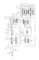
図1は、被検眼眼底の断層画像を取得して画像処理するシステム全体を示すブロック図である。符号1で示すものは、被検眼Eの眼底(網膜)Efを観察及び撮像する眼底カメラユニット1であり、照明光学系4、撮影光学系5、走査ユニット6を備えている。
照明光学系4は、ハロゲンランプ等の観察光源とキセノンランプ等の撮影光源を備え、これらの光源からの光は照明光学系を介して眼底Efに導かれて眼底を照明する。撮影光学系5は、対物レンズ、撮影レンズなどの光学系、CCD等の撮像装置を備え、眼底Efにより反射された撮影光を撮影光路に沿って撮像装置に導き、眼底Efの画像を撮影する。また、撮影光学系5は後述する眼底Efにより反射されたOCTユニット2から信号光をOCTユニット2に導く。走査ユニット6は、OCTユニット2からの信号光を図1のX方向及びY方向に走査するためのガルバノミラーなどを備えた機構である。
眼底カメラユニット1は、コネクタ7及び接続線8を介して眼底Efの断層画像を撮像するOCTユニット2と光学的に接続されている。
OCTユニット2は、例えばタイムドメイン方式あるいはフーリエドメイン方式で動作する公知のもので、波長が700nm~1100nmで数μm~数十μm程度の時間的コヒーレンス長の光を発光する低コヒーレンス光源20を有する。低コヒーレンス光源20からの光は、参照光と信号光に分割され、参照光は参照光路をたどって参照ミラーで反射される。一方、信号光は、接続線7、コネクタ8を介して眼底カメラユニット1に導かれ、走査ユニット6により眼底Ef上でX、Y方向に走査される。眼底Efで反射してOCTユニット2に戻ってきた信号光は、参照ミラーで反射した参照光と重畳され干渉光を発生する。干渉光はOCT信号検出装置21内で分光されて眼底の深度方向(Z方向)の情報を示すOCT信号が発生する。
画像処理装置3は、例えば、眼底カメラユニット1に内蔵されたマイクロコンピュータ、あるいは眼底カメラユニット1と接続されたパーソナルコンピュータ等によって構成される。画像処理装置3には、CPU、RAM、ROMなどで構成された制御部30が設けられ、制御部30は画像処理プログラムを実行することにより全体の画像処理を制御する。
表示部31は、例えば、LCDなどのディスプレイ装置によって構成され、画像処理装置3で生成あるいは処理された画像や、被検者に関する情報などの付随する情報を表示する。
操作部32は、例えば、マウスやキーボード、操作パネル等を有し、操作者が画像処理装置3などに指示を与えるために用いられる。
断層画像形成部41は、フーリエドメイン法(スペクトラルドメイン法)などの公知の解析方法を実行する専用の電子回路、または、前述のCPUが実行する画像処理プログラムにより実現され、OCT信号検出装置21が検出したOCT信号に基づいて、眼底Efの断層画像を形成する。断層画像形成部41で形成された断層画像は、例えば半導体メモリ、ハードディスク装置等により構成された記憶部42に格納される。記憶部42は、さらに上述した画像処理プログラムなども格納する。
画像処理部50は、基準画像作成手段51、算出手段52、選別手段53、生成手段54を有し、基準画像作成手段51は撮影された複数枚の断層画像から基準画像を選択ないし作成し、算出手段52は、基準画像と他の画像との類似度あるいは位置ずれ量を算出する。選別手段53は、算出された類似度あるいは位置ずれ量が設定値を満たす画像を判別ないし選別し、生成手段54は判別ないし選別された画像を加算平均して読撮用画像を生成する。画像処理部50における各手段あるいは各画像処理は、専用の電子回路を用いることにより、あるいは画像処理プログラムを実行することにより実現される。
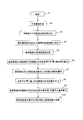
次に、本実施例での画像処理を図4に示すフローチャートを参照しながら説明する。この画像処理は、制御部30が記憶部42に格納された画像処理プログラムを読み出して実行することにより行われる。
まず、ステップS1において、被検眼の眼底の撮影を行う。被検眼Eと眼底カメラユニット1の位置合わせ(アライメント)を行ったあと、低コヒーレンス光源20をオンにして、OCTユニット2からの信号光を走査ユニット6でX,Y方向に掃引し、眼底Efを走査する。この状態が図2に図示されており、網膜の黄斑部が存在する領域Rが、X軸と平行な方向に、それぞれn本の走査線y1、y2、・・・、ynで走査される。
眼底Efで反射された信号光は、OCTユニット2で参照ミラーで反射された参照光と重畳される。それにより干渉光が発生し、OCT信号検出装置21からOCT信号が発生する。断層画像形成部41はOCT信号をフーリエ変換して眼底Efの断層画像を生成する。断層画像形成部41で生成された断層画像は記憶部42に格納される。
走査ユニット6による走査は、各走査線yi(i=1~n)毎に断層画像を形成するスライススキャンと、一つの走査線yj(i=j)による断層画像を形成するシングルスキャンがあり、スライススキャンの場合は、走査線ynによる走査が終わった後走査線y1による走査に戻り、これを繰り返す。一方シングルスキャンの場合は、一つの走査線yj(i=j)に沿った走査だけなので、y方向に信号光を掃引する走査ユニット6のガルバノミラーは固定され、x方向に信号光を掃引するガルバノミラーは、x方向に終端まで信号光を走査したら、開始端に戻って再び同じx方向に走査を開始しこれを繰り返す。
本実施例では、シングルスキャンで得られた断層画像の処理が行われるが、スライススキャンで行われた各断層画像は、異なる走査線でのシングルスキャンの断層画像の集合であるので、シングルスキャンで得られた断層画像の処理を、それぞれのスライススキャンで得られた断層画像に適用して同様の処理を行うことができる。
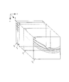
図3には、網膜の黄斑部のほぼ中心を通過する走査線yjで得られたxz断層画像(B-スキャン像)の異なる時間ti(i=1~N)での断層画像Ti(i=1~N)が図示されている。tiとti+1の時間間隔は走査線yjでのx方向の走査に要する時間に相当する。これらの断層画像Ti(i=1~N)は、断層画像形成部41で時間ti(i=1~N)毎に形成され、記憶部42に順次格納される。
被検眼は固視微動を起こすので、検者が同一箇所を撮影しているつもりであっても、実際には、それぞれの画像では、微妙に異なる位置を撮影する結果となる。従って、上記格納された同じ箇所の各断層画像は、xz方向に位置ずれを起こしている場合があり、構築される3次元断層画像の品質が劣化する。
そこで、本実施例では、Nを100から300として異なる時間での同一箇所のN枚の断層画像Ti(i=1~N)から基準画像を作成し、その基準画像に基づいて読影用の断層画像を生成する。なお、断層画像Ti(i=1~N)は、以下では、単に画像Ti(i=1~N)という。
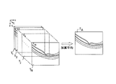
基準画像を作成するために、ステップS2において、図5aに示したようにN枚の画像Tiを記憶部42から読み出し、その平均画像TAを作成する。平均画像TAは、例えば、画素ごとの画素値の平均値、中央値、あるいは最頻出値により作成する。なお、平均画像TAはN枚の画像全部を用いるのではなく、その内の所定枚数の画像を選択し、その選択された画像を用いて平均画像を作成することもできる。なお、平均画像作成のために選択される画像は、病変部が撮影されている画像あるいは網膜上皮の位置が所定の範囲内にある画像とするのが好ましい。
続いて、ステップS3で、各画像Ti(i=1~N)と平均画像TAの類似度を算出手段52で算出する。この類似度を示す評価関数として例えば数1に示した相関係数を用いることができる。
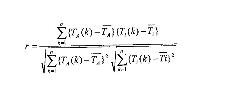
ここで,T(k)は画素値の集合(画素数n)、T(上に横線)は画素値の平均である。なお、各画像Tiとの類似度は、各画像を平行移動、回転、拡大縮小して平均画像TAとの位置合わせを行って相関係数を求めることにより行われるが、位置合わせを行わず相関係数を求めるようにしてもよい。また、類似度は相関係数でなく、各画像Tiと平均画像TAの対応する画素値の差(位置ずれ量)を用いて算出することもできる。また、相関係数あるいは位置ずれ量は画像全体で求めてもよいし、その一部領域(例えば病変部、特徴部のある領域)で求めるようにしてもよい。
ステップS4では、最大類似度を算出した画像を基準画像とする。このようにして作成された基準画像が図5bで符号TRで示されている。
なお、基準画像TRは、平均画像TAとの類似度が最大の画像ではなく、平均画像TAそのものを基準画像TRとしてもよく、あるいはステップS3で所定のしきい値を超える類似度を有する複数枚の画像を抽出し、その加算平均画像を基準画像とするようにしてもよい。
あるいは、全画像Ti(i=1~N)あるいはそのうち選択された画像を表示部31に表示し、操作者が基準画像を選択するようにしてもよい。操作者が一つだけ選択した場合にはその画像を、また複数選択した場合にはその加算平均画像を基準画像TRとする。この場合、病変部が撮影されている画像あるいは網膜上皮の位置が所定の範囲内にある画像を選択するようにする。
あるいは、撮影開始直後では固視微動は少ないので、最初の画像T1を基準画像としたり、最初の複数枚の画像Ti(例えば、i=1~10)の加算平均画像を基準画像としたりするようにしてもよい。
なお、上述したように平均画像に基づいて基準画像を作成するか、あるいは操作者が画像を指定することにより基準画像を作成するかを、操作部32で選択できるようにしてもよい。
このようにして基準画像TRが選択あるいは作成されたら、それを記憶部42に記憶するとともに、図5bに示したように、基準画像TRの特徴領域Cを決定する(ステップS5)。特徴領域Cとしては、合計輝度値が大きくなるか、輝度値のコントラスト(最大値、最小値)が大きいか、あるいはエッジ強度の合計値が大きくなる網膜層の領域あるいは病変のある領域を選択する。
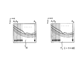
続いて、ステップS6において、基準画像TRの特徴領域Cで各画像Ti(i=1~N)との全体の位置ずれ量、類似度を算出手段52で算出する。この状態が図6に図示されている。位置ずれ量は各画像をx、z方向に移動させて基準画像TRの特徴領域Cとの類似度が最大になるx、z方向の移動量を求めることにより、また類似度は数1で相関係数を求めることにより算出する。なお、ステップS6の処理は特徴領域Cにおいて位置ずれ量、類似度を算出するのでなく、画像全体に基づいて位置ずれ量、類似度を算出するようにしてもよい。
次に、ステップS7において、設定値を満たす類似度を算出した画像を複数枚(M枚、Mは例えば30)を選別する。設定値は類似度しきい値として、所定の類似度しきい値を超える類似度を有する画像を選別手段53で判別ないし選別する。選別された各画像は記憶部42に格納しておく。なお、選別された画像枚数が少ない場合には、類似度しきい値を小さくして、Mが30近くなるようにする。図6には、ステップS7で行われる処理が図示されている。また、選別する画像を類似度でなく、基準画像TRが得られる時間の前後の所定時間帯内の画像としてもよい。例えば基準画像TRが時間tRで得られた場合、時間t(R-k)からt(R+k)内の画像を選別するようにしてもよい。
続いて、ステップS6で算出した位置ずれ量に基づき各画像Ti(i=1~M)の位置合わせを行い(ステップS8)、基準画像TRと各画像Ti(i=1~M)との局所領域毎の類似度と位置ずれ量を算出手段52で算出する(ステップS9)。局所領域は、x方向に所定画素数の幅を、z方向に定められた画素数の長さを有する領域であり、例えば図7aで示したようにz方向に延びるライン(幅が1画素分の幅)でAスキャン線Ai(i=1~k)と呼ばれるラインである。図7aに示したように、基準画像TRと各画像Ti(i=1~M)との類似度と位置ずれ量を、各Aスキャン線Ai(i=1~k)毎に算出する。類似度の計算には、数1に示したような相関係数を用いることができる。
このようにして基準画像TRと各画像Ti(i=1~M)とのAスキャン線Ai(i=1~k)ごとの類似度と位置ずれ量を算出したら、生成手段54でAスキャン線Ai毎にその位置ずれ量を補正して各画像Tiを基準画像に加算し(ステップS10)、加算枚数(M)+1で除算してその平均を求めることにより図7bに示したような読影用画像TDを生成する。
また、Aスキャン線Aiはx方向に全体に設定されているが、その本数を限定して一部の領域、例えば特徴領域Cだけに設定するようにしてもよい。また、Aスキャン線は、z方向に延びるラインであるが、そのラインを中心にしてx方向に幅を有する矩形状(短冊状)の領域とし、その領域に基づいて類似度、位置ずれ量を算出することもできる。
また、ステップS10で補正、加算する画像を、基準画像との局所領域毎の類似度あるいは位置ずれ量が所定の設定値を満たす画像に制限するようにしてもよい。たとえば、局所領域毎の類似度が所定の類似度しきい値より大きな画像、あるいは局所領域毎の位置ずれ量が所定の位置ずれ量しきい値より小さな画像に対してステップS10で補正、加算を行い、その他の画像は加算しないようにすることができる。また、制限しすぎて最低加算枚数が得られない場合には、類似度しきい値を小さく、また位置ずれ量しきい値を大きくして加算枚数を増加させることができる。
本実施例では、基準画像を選択ないし作成し(ステップS2~S4)、その基準画像と類似度の大きい画像を選別することにより(ステップS7)、固視微動などに基づく位置ずれ量が大きな画像が除去され、更に選別された画像に対しては、Aスキャン線ごとの位置ずれ量を補正して加算し(ステップS10)、最終的に一枚の画像を生成するようにしているので、高品質の読影用画像を生成することができる。
図7a、図7bに示した実施例では、基準画像TRと各画像Ti(i=1~M)との位置ずれ量を、各Aスキャン線Ai(i=1~k)毎に算出し、各画像TiをAスキャン線毎に位置ずれ量を補正しているので、Aスキャン線毎に補正された画像Tiが作成される。これに対して、画像Tiの各Aスキャン線毎にAスキャン線の画像に類似する、あるいは該画像と同一の画像を基準画像の中から探索し、各Aスキャン線の画像を基準画像内の探し出した画像に加算平均して各画像の位置ずれを補正するようにすることができる。この例が図11から図13に図示されている。
図11は、画像処理部60を除き図1と同様な構成であるので、図1と同じあるいは同様な構成についてはその説明を省略する。
画像処理部60は、基準画像作成手段61、画像選択手段62、画像分割手段63、領域設定手段64、位置ずれ量検出手段65、加算平均手段66を有する。基準画像作成手段61は、基準画像作成手段51と同様に、同一箇所を撮影した複数枚の断層画像から基準画像を選択ないし作成する。画像選択手段62は、同一箇所を撮影した複数の画像からその全部あるいはその内の所定枚数の画像を選択する。画像分割手段63は、画像選択手段62により選択された断層画像を複数の領域に分割し、領域設定手段64は、後述するように選択画像内に評価領域Aを設定し、基準画像内に探索領域Bを設定する。位置ずれ量検出手段65は、画像分割手段63により分割された領域毎に、分割領域の画像に対応する画像を基準画像の中から探索し、分割領域の画像と該画像に対応する基準画像内の画像との位置ずれ量を検出する。加算平均手段66は、検出された位置ずれ量に基づいて分割領域毎に、分割領域の画像を基準画像内の対応する画像に加算平均して位置ずれが補正された画像を生成する。画像処理部60における各手段あるいは各画像処理は、専用の電子回路を用いることにより、あるいは画像処理プログラムを実行することにより実現される。
図12には、基準画像作成手段61により選択ないし作成された基準画像TRと、画像選択手段62により選択された複数の画像Ti(i=1~M、以下選択画像という)が図示されている。好ましくは、選択画像Tiは、同一箇所を撮影した多数の画像のうち基準画像TRとの類似度が大きなM枚の画像が選択される。基準画像TRと選択画像Tiはそれぞれn×k(例えばn=1000、k=2048)の画素からなる画像とて描かれている。
本実施例では、画像分割手段63により各選択画像TiはAスキャン線に沿ってx方向がAスキャン線の幅(1画素)、z方向がk画素の長さのn個の領域に分割される。位置ずれ量検出手段65は、このn個の分割領域のそれぞれに対して、分割領域の画像に対応する画像を位置ずれ補正の基準となる基準画像TRの中から探索し、探し出した画像と該分割領域の画像との位置ずれ量を検出する。1xk画素の分割領域の画像を以下ではAスキャン画像という。以下、この位置ずれ量の検出を図13のフローチャートを用いて説明する。
図13のステップS51、S53では変数が初期化され(i=1、j=1)、ステップS52で選択画像Tiに対する処理が行われているものとする。ステップS54で選択画像Tiのj番目のAスキャン画像Sjが取得される。選択画像Tiの分割並びにj番目のAスキャン像Sjが図12の下段中央に図示されている。
図12の下段右に示したように、選択画像Tiには、そのj番目のAスキャン画像Sj(幅1画素)を中心にx方向左右にそれぞれ所定画素付加した、例えば幅21画素×高さ300画素の相関を評価する評価領域Aが設定される。この評価領域Aは、眼底の深さ方向の網膜組織が撮影されている領域を含むように設定される。一方、基準画像TRには、選択画像の評価領域Aに対応する評価領域A’が設定される。選択画像Tiの評価領域Aにある4隅の画素の座標値は分かるので、その4つの座標値をもつ画素の位置を基準画像TRに求めれば、基準画像TR内に評価領域A’を設定することができる。また、基準画像TRには、評価領域A’を含みそれより大きな、例えば幅31画素×高さ400画素の相関を評価する探索領域Bが設定される。
選択画像Tiの評価領域Aの画像を基準画像TRの探索領域B内で、相関値が最大になるようにx、z方向にずらして評価領域Aの画像に対応する画像を基準画像TRの中から探索する。相関値が最大となるようなずれ量を求めることによりAスキャン画像Sjの基準画像TRに対するx、z方向の位置ずれ量Δx、Δzが検出される。この工程が図12のステップS55、S56に図示されている。相関値の計算は、例えば数1の式と同様な式を用いることができる。
このように、x、z方向の位置ずれ量Δx、Δzを求めたら、選択画像Tiの(j、za)座標の画素値を基準画像TRの{(j+Δx)、(za+Δz)}座標(a=1~k)の画素値に加算する(ステップS57)。この加算処理は、選択画像Tiのj番目のAスキャン画像Sjを、そのAスキャン画像に類似する、又はほぼ同一の基準画像部分に加算する(重ね合わせる)処理であり、これにより、選択画像内に被検眼の固視微動による画像のずれがあっても、そのずれを良好に補正できることが可能になる。また、評価領域AをAスキャン画像Sjを中心にx方向左右にそれぞれ所定画素付加した大きな領域とすることにより、x方向の位置ずれも精度よく検出でき、さらに、基準画像TRの探索領域Bを選択画像Tiの評価領域Aより大きくすることにより大きな位置ずれも良好に補正することができる。
j番目のAスキャン画像Sjの基準画像への加算が終了すると、jが+1増分され(ステップS58)、次の(j+1)番目のAスキャン画像Sj+1が取得され、同様な処理で評価領域A、探索領域Bが設定されるとともに、基準画像TRに対するずれ量Δx、Δzが検出され、基準画像TRへの加算処理が行われる(ステップS54~S57)。
このような処理がn番目の最終Aスキャン画像Snまで終了すると、選択画像Tiのすべての分割画像に対する位置ずれ検出並びにその補正が終了するので、iが+1増分され(ステップS59、S60)、次の選択画像Ti+1に対して、ステップS53~S59の処理が行われる。
最後の選択画像TMまで処理が終了すると(ステップS61の肯定)、全ての選択画像に対して上記加算処理が終了するので、加算平均手段66は基準画像TRの各画素の画素値の加算合計値を(加算回数+1)で除算して平均値を求める(ステップS62)。各選択画像のAスキャン画像のずれ次第で、複数の選択画像の異なる位置のAスキャン画像の画素値が、基準画像の同じAスキャン画像の画素値に加算される場合があるので、選択画像がM枚であっても、全ての画素に対して(M+1)で除算が行われるわけではない。
このように、各選択画像Tiの分割領域の画像(Aスキャン画像)毎に位置ずれ検出と補正が行われ、選択画像内に被検眼の固視微動による画像のずれがあっても、そのずれを良好に補正できることが可能になる。また、Aスキャン画像を中心にx方向左右にそれぞれ所定画素付加した大きな領域を評価領域Aとし、評価領域Aの画像に対応する画像を基準画像の中から探索することにより、各方向の位置ずれも精度よく検出でき、さらに、基準画像に設定される探索領域Bを評価領域Aに対応する領域A’より大きくすることにより大きな位置ずれにも対処できるようになる。また、探索領域Bは限定した領域であるので、探索領域を超えては位置ずれ検出は行われず、検出できないような大きなずれを不必要に検出すること防止して画像処理速度が低下することを防止できる。
なお、選択画像Tiの各Aスキャン画像に設定される評価領域Aは、眼底の深さ方向の網膜組織が撮影されている領域を含むように設定されるが、深さ方向の組織領域はx方向で異なるので、x方向の走査に従って変化させると好ましい。図12に示した例では、網膜組織は右に行くにしたがい下方に延びているので、評価領域Aも下方に設定される。
上述した例では、選択された画像が複数の領域に分割され、選択画像の分割領域毎に、分割領域の画像が基準画像のどの部分の画像に対応するかが探索され、選択画像の分割領域の画像が探索された基準画像の画像部分に加算され、位置ずれが補正された画像が生成されている。
これに対して、基準画像のある画像が選択画像のどの部分の画像に対応するかを探索して位置ずれを検出し、補正を行うようにしてもよい。この場合には、図14に示したように、基準画像が複数の領域に分割され、基準画像の分割領域毎に、分割領域の画像が選択画像のどの部分の画像に対応するかが探索される。
図14に示す実施例では、画像分割手段63は、断層画像の基準となる基準画像TRを複数の領域に分割し、領域設定手段64は、基準画像内に評価領域Aを設定し、選択画像Ti内に評価領域Aより大きな探索領域Bを設定する。位置ずれ量検出手段65は、基準画像TRの分割された領域毎に、分割領域の画像に対応する画像を選択画像Tiの中から探索し、分割領域の画像と該画像に対応する選択画像Ti内の画像との位置ずれ量を検出する。加算平均手段66は、検出された位置ずれ量に基づいて分割領域毎に、基準画像TRの分割領域の画像に選択画像Ti内の対応する画像を加算平均して位置ずれが補正された画像を生成する。平均画像の形成は、図13に示す流れと同様な流れで行われる。選択画像Ti(i=1~M)に対して、基準画像の各分割領域の画像に対応する画像が選択画像内でそれぞれ探索され、探索された選択画像の各画像が基準画像の対応する分割領域の画像にそれぞれ加算され、平均化が行われる。
また、上述した実施例では、選択画像あるいは基準画像は1画素幅のAスキャン画像に細分されたが、Aスキャン線を中心にしてx方向に幅を有する矩形状(短冊状)の領域、つまりx方向に2画素以上の幅を有し、長さがk画素の領域に細分するようにしてもよい。その場合も、評価領域Aはx方向に細分した領域より大きな幅を有する領域に設定し、基準画像あるいは選択画像に設定される探索領域Bは、その領域を含む更に大きな領域に設定することはもちろんである。
上述した処理は、時間が異なる走査線yjでの同じ断層画像N枚から高品質の断層画像を生成するものであったが、他の走査線yi(i=jを除くi=1~n)での断層画像でも同様な処理を行って該走査線での高品質の断層画像を生成することもできる。従って、全ての走査線yi(i=1~n)での断層画像に対して高品質の断層画像が生成され、最終的に高品質の3次元断層画像を生成することができる。
上述した図1に示す実施例では、時間が異なるN枚の画像Ti(i=1~N)を取得し、これらの画像Tiを一旦記憶部42に格納し、格納された画像から基準画像を作成しているので、撮影を行いながら画像処理を行うことができない。
これに対して、撮影を行いながらリアルタイムで画像処理を行う実施例が図8にフローチャートの形で図示されている。以下、図8を参照してこの実施例を説明する。
まず、ステップS20で変数iが1に設定される。図4のステップS1で説明したように、一つの走査線yjでシングルスキャンが行われ、被検眼眼底が撮影されて(ステップS21)、時間t1の画像T1が断層画像形成部41で形成される。時間t1での撮影は、固視が安定した状態で行うようにする。
実施例2では、この1枚目の画像T1が基準画像TRに定められ(ステップS22)、記憶部42に記憶される。続いて、基準画像TRの特徴領域Cが設定される(ステップS23)。特徴領域Cとしては、ステップS5で説明したように、合計輝度値が大きくなるか、輝度値のコントラスト(最大値、最小値)が大きいか、あるいはエッジ強度の合計値が大きくなる網膜層の領域あるいは病変のある領域が選択される。
ステップS24でiが+1され、iがN(例えばN=100)を超えたかが判断される(ステップS25)。i=2なので、判断が否定され、2回目の撮影(シングルスキャン)が行われ(ステップS27)、画像T2が形成される。
続いて、ステップS28で基準画像TRと画像Ti(i=2)の特徴領域Cでの全体の位置ずれ量、類似度が算出される。この処理は図4のステップS6と同様に行われる。
続くステップS29で、画像Ti(i=2)の基準画像TRに対する類似度が設定値を満たすかが判断される。設定値を満たす場合(例えば類似度が所定の類似度しきい値を超えている場合)には、ステップS8~S10と同様なステップS30~S32の処理が行われる。
そのあと、ステップS24に戻り、iが増分される。ステップS29において画像Tiの類似度が設定値を満たさない場合も、その画像が不採用となり、ステップS24に戻る。
以下、nが増分される毎に同様な処理が画像TNまで行われ、その後ステップS25の判断が満たされ、処理が終了する(ステップS26)。その段階で、ステップS29で採用された全ての画像が補正されて基準画像に加算されているので、その平均を求めることにより高品質の読影用画像を生成することができる。
この実施例では、ステップS28からステップS32までの処理に要する時間が一回のx方向のスキャンに要する時間より短い場合はそのまま、一方、長い場合にはx方向のスキャンに要する時間を長くすることにより、つまり走査ユニット6のx方向走査用のガルバノミラーの走査速度を遅くすることにより、撮影を行いながらリアルタイムで画像処理を行うことができ、短時間で高品質の画像を生成することができる。
上記実施例1における異なる時間ti(i=1~N)での各画像Ti(i=1~N)(図3)、あるいは基準画像との類似度が大きいM枚の画像Ti(i=1~M)(図6)は、それぞれ群をなした静止画像の集まりであり、個々の画像を表示して読影することは、N、Mの数が大きくなるほど困難になる。
そこで、各画像Tiをコマ撮りした静止画像(フレーム画像)として扱いアニメーション化して動画表示させるようにする。
その流れが図9にフローチャートの形で図示されており、記憶部42に格納されている動画表示プログラムを制御部30のCPUが実行することにより動画表示が行われる。
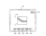
図10aに示したように、表示部31のモニタに現れる「開始」ボタン31aをクリックすると、変数iが初期化され(ステップS40)、画像T1が記憶部42から読み出され(ステップS41)、画像T1が表示部31のモニタ画面に表示される(ステップS42)。この表示は時間Ttimeが所定の時間Toを超えるまで継続され、時間To経過後(ステップS43のYES)、変数iが+1増分されてi=2となり(ステップS44)、ステップS45の判断が否定されて、次の画像T2が読み出されて表示される(ステップS41、S42)。以後、同様なループを繰り返し、i>Nとなった時点(ステップS45のYES)で処理が終了する。
制御部30は、所定時間To毎に順次表示される画像が疑似的に動画として表示されるように、所定時間Toを短い時間(例えば、1/10~1/60sec)に設定し、また順次表示される画像の表示位置を図10a、図10bに示した位置に制御する。図10aに示した例では、前の画像Ti-1が消去され、同じ位置に次の画像Tiが表示される。図10bに示した例では、前の画像Ti-1に対してx方向及び/又はz方向に所定量(例えば10画素程度)ずらした位置に次の画像Tiが表示される。いずれの表示を行うかは、操作部32により選択できるようにしておく。
このような制御部30の制御により、一連の画像Ti(i=1~N)が所定時間To毎に順次読み出されアニメーション化されて動画として表示される。
このような動画表示において、画像Tiに時間的な変化があれば、その変化が疑似的に動きとして表示されるので、例えば、固視微動があったときには、その固視微動が動画表示されることになる。従って、検者は、固視微動のあった画像(動きが現れた画像)を視認した場合には、「停止」ボタン31cをクリックして動画表示を一時停止させることができる。何番目の画像が表示されているかは、右上のボタン31fに時間Toごとに表示されるので、検者は、固視微動のあった画像を特定することができ、図4のステップS2の平均画像作成時に除外するなどして、より高品質の基準画像を作成することができる。
また、動画として表示される画像は、断層画像形成部41で形成された生の画像Ti(i=1~N)だけでなく、各画像Ti(i=1~N)に対してノイズ除去、位置ずれ補正などの画像処理を行った一連の画像でもよく、その場合には、動画表示を行うことにより、目的とする画像処理が行われたかを確認することができる。
また、基準画像との類似度が大きいM枚の画像Ti(i=1~M)を、図9のフローチャートに従って動画表示すると、理想的には、各画像間TiとTi-1には殆ど変化が現れないので、動画表示を行っても、動きは検出されず、検者は、基準画像との類似度が大きい画像が選別されたこと(ステップS7)を確認することができ、高品質の読影画像の生成に役立てることができる。また、動きが視認された場合には、「停止」ボタン31cを操作し、その画像を特定して、排除するようにすることもできる。
以上は、「開始」ボタン31aを操作した時の例であったが、「繰返」ボタン31bを操作すると、ステップS45の判断が肯定された場合、再びステップS40に戻る無限ループが実行され、画像Ti(i=1~N)が繰り返し動画表示される。この繰り返し表示を一時停止する場合には、「停止」ボタン31cを、終了させる場合は「終了」ボタン31eを操作する。「再開」ボタン31dは、一時停止した動画表示を再開する場合に用いられる。
なお、動画表示させる画像は、すべての画像Ti(i=1~M、1~N)ではなく、飛び飛びの画像、つまり画像iの次に画像Ti+k(k=2、3、.....)の画像を順次表示するようにしてもよい。
1 眼底カメラユニット
2 OCTユニット
3 画像処理装置
4 照明光学系
5 撮影光学系
6 走査ユニット
7 コネクタ
8 接続線
20 低コヒーレンス光源
21 OCT信号検出装置
30 制御部
31 表示部
32 操作部
41 断層画像形成部
42 記憶部
50、60 画像処理部
51、61 基準画像作成手段
52 算出手段
53 選別手段
54 生成手段
62 画像選択手段
63 画像分割手段
64 領域設定手段
65 位置ずれ量検出手段
66 加算平均手段
2 OCTユニット
3 画像処理装置
4 照明光学系
5 撮影光学系
6 走査ユニット
7 コネクタ
8 接続線
20 低コヒーレンス光源
21 OCT信号検出装置
30 制御部
31 表示部
32 操作部
41 断層画像形成部
42 記憶部
50、60 画像処理部
51、61 基準画像作成手段
52 算出手段
53 選別手段
54 生成手段
62 画像選択手段
63 画像分割手段
64 領域設定手段
65 位置ずれ量検出手段
66 加算平均手段
Claims (24)
- 同一箇所を撮影した複数の画像を基準画像と比較して基準画像との位置ずれを検出し、位置ずれが補正された画像を生成する画像処理装置であって、
前記複数の画像の全部あるいはその内の所定枚数の画像を選択する画像選択手段と、
前記選択された画像を複数の領域に分割する画像分割手段と、
分割された領域毎に、分割された領域の画像に対応する画像を基準画像の中から探索し、該探索された画像に分割された領域の画像を加算する加算手段と、を備え、
前記加算された画像を平均して位置ずれが補正された画像を生成することを特徴とする画像処理装置。 - 同一箇所を撮影した複数の画像を基準画像と比較して基準画像との位置ずれを検出し、位置ずれが補正された画像を生成する画像処理装置であって、
前記複数の画像の全部あるいはその内の所定枚数の画像を選択する画像選択手段と、
前記基準画像を複数の領域に分割する画像分割手段と、
分割された領域毎に、分割された領域の画像に対応する画像を選択画像の中から探索し、該探索された画像を分割された領域の画像に加算する加算手段と、を有し、
前記加算された画像を平均して位置ずれが補正された画像を生成することを特徴とする画像処理装置。 - 前記分割された領域を含み該領域より大きな評価領域が設定され、分割された領域の画像に対応する画像の探索が行われることを特徴とする請求項1又は2に記載の画像処理装置。
- 前記評価領域を含み該領域より大きな探索領域が設定され、該探索領域内で分割された領域の画像に対応する画像の探索が行われることを特徴とする請求項3に記載の画像処理装置。
- 前記画像はOCT装置により取得された被検眼網膜の断層画像であり、該断層画像がAスキャン画像に分割されて画像の探索が行われることを特徴とする請求項1から4のいずれか1項に記載の画像処理装置。
- 同一箇所を撮影した複数の画像を基準画像と比較して基準画像との位置ずれを検出し、位置ずれが補正された画像を生成する画像処理方法であって、
前記複数の画像の全部あるいはその内の所定枚数の画像を選択する画像選択工程と、
前記選択された画像を複数の領域に分割する画像分割工程と、
分割された領域毎に、分割された領域の画像に対応する画像を基準画像の中から探索し、該探索された画像に分割された領域の画像を加算する加算工程と、を備え、
前記加算された画像を平均して位置ずれが補正された画像を生成することを特徴とする画像処理方法。 - 同一箇所を撮影した複数の画像を基準画像と比較して基準画像との位置ずれを検出し、位置ずれが補正された画像を生成する画像処理方法であって、
前記複数の画像の全部あるいはその内の所定枚数の画像を選択する画像選択工程と、
前記基準画像を複数の領域に分割する画像分割工程と、
分割された領域毎に、分割された領域の画像に対応する画像を選択画像の中から探索し、該探索された画像を分割された領域の画像に加算する加算工程と、を有し、
前記加算された画像を平均して位置ずれが補正された画像を生成することを特徴とする画像処理方法。 - 同一箇所を撮影した複数枚の画像の中から基準画像を選択あるいは作成する基準画像作成手段と、
前記選択あるいは作成された基準画像と他の画像との類似度を算出する算出手段と、
算出した類似度が設定値を満たす画像を選別する選別手段と、
選別された画像を加算平均して読影用画像を生成する生成手段と、
を備えたことを特徴とする画像処理装置。 - 前記基準画像作成手段は、複数枚の画像の全部あるいはその内の所定枚数の画像を選択し、その選択された画像の平均画像に基づいて基準画像を作成することを特徴とする請求項8に記載の画像処理装置。
- 前記基準画像作成手段は、前記複数枚の画像のうち選択された一枚の画像を基準画像とすることを特徴とする請求項8に記載の画像処理装置。
- 前記複数枚の画像の全部あるいはその内の所定枚数の画像を選択し、その選択された画像の平均画像に基づいて基準画像を作成するか、あるいは複数枚の画像のうち選択された一枚の画像を基準画像とするかを選択できることを特徴とする請求項10に記載の画像処理装置。
- 前記画像は被検眼網膜の断層画像であり、病変部が撮影されている画像あるいは網膜上皮の位置が所定の範囲内にある画像が基準画像を作成するための画像として選択されることを特徴とする請求項8から11のいずれか1項に記載の画像処理装置。
- 前記類似度が画像全体あるいはその一部領域での相関係数あるいは位置ずれ量を算出することにより求められることを特徴とする請求項8から12のいずれか1項に記載の画像処理装置。
- 前記生成手段は、設定された複数の局所領域毎に基準画像との位置ずれ量を算出し、算出された位置ずれ量を局所領域毎に補正して基準画像に加算しその平均を求めることにより読影用画像を生成することを特徴とする請求項8から13のいずれか1項に記載の画像処理装置。
- 前記生成手段は、算出された局所領域毎の類似度が所定の類似度しきい値より大きな画像あるいは局所領域毎の位置ずれ量が所定の位置ずれ量しきい値より小さい画像に対して前記補正、加算を行うことを特徴とする請求項14に記載の画像処理装置。
- 最低加算枚数が得られない場合には、前記類似度しきい値あるいは位置ずれ量しきい値を調整することを特徴とする請求項15に記載の画像処理装置。
- 同一箇所を撮影した一連の画像あるいは該一連の画像に対してそれぞれ画像処理された一連の画像を格納する記憶部と、
前記記憶部に格納された一連の画像を所定時間毎に順次読み出して表示部に表示させる制御部と、を備え、
前記制御部は、所定時間毎に順次表示される画像が動画として表示されるように、前記所定時間の長さと順次表示される画像の表示位置を制御することを特徴とする画像処理装置。 - 同一箇所を撮影した複数枚の画像の中から基準画像を選択あるいは作成する基準画像作成工程と、
前記選択あるいは作成された基準画像と他の画像との類似度を算出する算出工程と、
算出した類似度が設定値を満たす画像を選別する選別工程と、
選別された画像を加算平均して読影用画像を生成する生成工程と、
を有することを特徴とする画像処理方法。 - 複数枚の画像の全部あるいはその内の所定枚数の画像を選択し、その選択された画像の平均画像に基づいて基準画像を作成することを特徴とする請求項18に記載の画像処理方法。
- 前記複数枚の画像のうち一枚の画像を選択し、その選択された画像を基準画像とすることを特徴とする請求項18に記載の画像処理方法。
- 撮影した最初の画像を基準画像に定める第1工程と、
次に同一箇所を撮影する第2工程と、
第2工程で撮影された画像と定めた基準画像との類似度が設定値を満たす画像を採用し、それ以外の画像を不採用とする第3工程と、
採用画像を基準画像に加算する第4工程と、
を有し、
撮影枚数が所定枚数になるまで第2から第4工程を繰り返し、採用画像を順次基準画像に加算して平均することにより読影用画像を生成することを特徴とする画像処理方法。 - 同一箇所を撮影した一連の画像あるいは該一連の画像に対してそれぞれ画像処理された一連の画像を所定時間毎に順次記憶部から読み出して表示部に表示する工程を有し、
所定時間毎に順次表示される画像が動画として表示されるように、前記所定時間の長さと順次表示される画像の表示位置が制御されることを特徴とする画像処理方法。 - 請求項6、7、18から22のいずれか1項に記載の画像処理方法をコンピュータに実行させることを特徴とする画像処理プログラム。
- 請求項23に記載の画像処理プログラムを格納したコンピュータにより読み取り可能な記録媒体。
Priority Applications (1)
| Application Number | Priority Date | Filing Date | Title |
|---|---|---|---|
| JP2014554209A JP6608138B2 (ja) | 2012-12-28 | 2013-10-30 | 画像処理装置、画像処理方法、画像処理プログラム及びそのプログラムを格納した記録媒体 |
Applications Claiming Priority (2)
| Application Number | Priority Date | Filing Date | Title |
|---|---|---|---|
| JP2012-287403 | 2012-12-28 | ||
| JP2012287403 | 2012-12-28 |
Publications (1)
| Publication Number | Publication Date |
|---|---|
| WO2014103501A1 true WO2014103501A1 (ja) | 2014-07-03 |
Family
ID=51020600
Family Applications (1)
| Application Number | Title | Priority Date | Filing Date |
|---|---|---|---|
| PCT/JP2013/079447 Ceased WO2014103501A1 (ja) | 2012-12-28 | 2013-10-30 | 画像処理装置、画像処理方法、画像処理プログラム及びそのプログラムを格納した記録媒体 |
Country Status (2)
| Country | Link |
|---|---|
| JP (1) | JP6608138B2 (ja) |
| WO (1) | WO2014103501A1 (ja) |
Cited By (12)
| Publication number | Priority date | Publication date | Assignee | Title |
|---|---|---|---|---|
| JP2016047100A (ja) * | 2014-08-27 | 2016-04-07 | キヤノン株式会社 | 画像処理装置、画像処理方法及びプログラム |
| JP2017018202A (ja) * | 2015-07-08 | 2017-01-26 | キヤノン株式会社 | 画像生成装置および画像生成方法 |
| JP2017159034A (ja) * | 2016-03-10 | 2017-09-14 | キヤノン株式会社 | 光干渉断層撮影におけるモーションアーチファクトの除去のための方法およびシステム |
| JP2018164814A (ja) * | 2018-08-03 | 2018-10-25 | キヤノン株式会社 | 画像処理装置及び画像処理装置の作動方法 |
| JP2019063353A (ja) * | 2017-10-03 | 2019-04-25 | 富士通株式会社 | プログラム、情報処理方法及び情報処理装置 |
| JP2019084400A (ja) * | 2019-03-13 | 2019-06-06 | キヤノン株式会社 | 画像処理装置、画像処理方法及びプログラム |
| KR20190070718A (ko) * | 2017-12-13 | 2019-06-21 | 한국생산기술연구원 | 영역 분할 기법에 기반한 화질 개선 광간섭 단층 촬영 장치 및 그 영상 처리 방법 |
| EP3714770A1 (en) * | 2019-03-29 | 2020-09-30 | Nidek Co., Ltd. | Ophthalmological image processing apparatus |
| JP2020162926A (ja) * | 2019-03-29 | 2020-10-08 | 株式会社ニデック | 眼科撮影装置、および、眼科用画像処理プログラム |
| CN113934495A (zh) * | 2021-10-14 | 2022-01-14 | 北京自如信息科技有限公司 | 一种移动端图像环视方法、系统和移动设备 |
| CN116957954A (zh) * | 2023-05-17 | 2023-10-27 | 上海英医达医疗器械用品有限公司 | 影像偏移校正方法及影像偏移校正系统 |
| JP2025100457A (ja) * | 2023-12-22 | 2025-07-03 | オプトス ピーエルシー | 網膜画像におけるノイズ低減 |
Citations (8)
| Publication number | Priority date | Publication date | Assignee | Title |
|---|---|---|---|---|
| JP2005228303A (ja) * | 2004-01-14 | 2005-08-25 | Matsushita Electric Ind Co Ltd | 動きベクトル検出装置 |
| JP2010110391A (ja) * | 2008-11-05 | 2010-05-20 | Nidek Co Ltd | 眼科撮影装置 |
| JP2010110393A (ja) * | 2008-11-05 | 2010-05-20 | Nidek Co Ltd | 眼科撮影装置 |
| JP2010110392A (ja) * | 2008-11-05 | 2010-05-20 | Nidek Co Ltd | 眼科撮影装置 |
| WO2011052602A1 (ja) * | 2009-10-27 | 2011-05-05 | 株式会社 日立メディコ | 超音波イメージング装置、超音波イメージング方法および超音波イメージング用プログラム |
| JP2011165045A (ja) * | 2010-02-12 | 2011-08-25 | Tokyo Institute Of Technology | 画像処理装置 |
| JP2011254959A (ja) * | 2010-06-08 | 2011-12-22 | Canon Inc | 画像処理装置、画像処理方法、及びプログラム |
| JP2012249715A (ja) * | 2011-05-31 | 2012-12-20 | Nidek Co Ltd | 眼底撮影装置 |
-
2013
- 2013-10-30 WO PCT/JP2013/079447 patent/WO2014103501A1/ja not_active Ceased
- 2013-10-30 JP JP2014554209A patent/JP6608138B2/ja active Active
Patent Citations (8)
| Publication number | Priority date | Publication date | Assignee | Title |
|---|---|---|---|---|
| JP2005228303A (ja) * | 2004-01-14 | 2005-08-25 | Matsushita Electric Ind Co Ltd | 動きベクトル検出装置 |
| JP2010110391A (ja) * | 2008-11-05 | 2010-05-20 | Nidek Co Ltd | 眼科撮影装置 |
| JP2010110393A (ja) * | 2008-11-05 | 2010-05-20 | Nidek Co Ltd | 眼科撮影装置 |
| JP2010110392A (ja) * | 2008-11-05 | 2010-05-20 | Nidek Co Ltd | 眼科撮影装置 |
| WO2011052602A1 (ja) * | 2009-10-27 | 2011-05-05 | 株式会社 日立メディコ | 超音波イメージング装置、超音波イメージング方法および超音波イメージング用プログラム |
| JP2011165045A (ja) * | 2010-02-12 | 2011-08-25 | Tokyo Institute Of Technology | 画像処理装置 |
| JP2011254959A (ja) * | 2010-06-08 | 2011-12-22 | Canon Inc | 画像処理装置、画像処理方法、及びプログラム |
| JP2012249715A (ja) * | 2011-05-31 | 2012-12-20 | Nidek Co Ltd | 眼底撮影装置 |
Cited By (19)
| Publication number | Priority date | Publication date | Assignee | Title |
|---|---|---|---|---|
| JP2016047100A (ja) * | 2014-08-27 | 2016-04-07 | キヤノン株式会社 | 画像処理装置、画像処理方法及びプログラム |
| JP2017018202A (ja) * | 2015-07-08 | 2017-01-26 | キヤノン株式会社 | 画像生成装置および画像生成方法 |
| JP2017159034A (ja) * | 2016-03-10 | 2017-09-14 | キヤノン株式会社 | 光干渉断層撮影におけるモーションアーチファクトの除去のための方法およびシステム |
| US10080492B2 (en) | 2016-03-10 | 2018-09-25 | Canon Kabushiki Kaisha | Method and system for motion artefacts removal in optical coherence tomography |
| JP7119327B2 (ja) | 2017-10-03 | 2022-08-17 | 富士通株式会社 | プログラム、情報処理方法及び情報処理装置 |
| JP2019063353A (ja) * | 2017-10-03 | 2019-04-25 | 富士通株式会社 | プログラム、情報処理方法及び情報処理装置 |
| KR102062372B1 (ko) * | 2017-12-13 | 2020-01-03 | 한국생산기술연구원 | 영역 분할 기법에 기반한 화질 개선 광간섭 단층 촬영 장치 및 그 영상 처리 방법 |
| KR20190070718A (ko) * | 2017-12-13 | 2019-06-21 | 한국생산기술연구원 | 영역 분할 기법에 기반한 화질 개선 광간섭 단층 촬영 장치 및 그 영상 처리 방법 |
| JP2018164814A (ja) * | 2018-08-03 | 2018-10-25 | キヤノン株式会社 | 画像処理装置及び画像処理装置の作動方法 |
| JP2019084400A (ja) * | 2019-03-13 | 2019-06-06 | キヤノン株式会社 | 画像処理装置、画像処理方法及びプログラム |
| EP3714770A1 (en) * | 2019-03-29 | 2020-09-30 | Nidek Co., Ltd. | Ophthalmological image processing apparatus |
| JP2020162926A (ja) * | 2019-03-29 | 2020-10-08 | 株式会社ニデック | 眼科撮影装置、および、眼科用画像処理プログラム |
| US11508062B2 (en) | 2019-03-29 | 2022-11-22 | Nidek Co., Ltd. | Ophthalmological image processing apparatus |
| JP7318272B2 (ja) | 2019-03-29 | 2023-08-01 | 株式会社ニデック | 眼科撮影装置、および、眼科用画像処理プログラム |
| CN113934495A (zh) * | 2021-10-14 | 2022-01-14 | 北京自如信息科技有限公司 | 一种移动端图像环视方法、系统和移动设备 |
| CN113934495B (zh) * | 2021-10-14 | 2024-05-24 | 北京自如信息科技有限公司 | 一种移动端图像环视方法、系统和移动设备 |
| CN116957954A (zh) * | 2023-05-17 | 2023-10-27 | 上海英医达医疗器械用品有限公司 | 影像偏移校正方法及影像偏移校正系统 |
| CN116957954B (zh) * | 2023-05-17 | 2025-11-28 | 上海英医达医疗器械用品有限公司 | 影像偏移校正方法及影像偏移校正系统 |
| JP2025100457A (ja) * | 2023-12-22 | 2025-07-03 | オプトス ピーエルシー | 網膜画像におけるノイズ低減 |
Also Published As
| Publication number | Publication date |
|---|---|
| JP6608138B2 (ja) | 2019-11-20 |
| JPWO2014103501A1 (ja) | 2017-01-12 |
Similar Documents
| Publication | Publication Date | Title |
|---|---|---|
| JP6608138B2 (ja) | 画像処理装置、画像処理方法、画像処理プログラム及びそのプログラムを格納した記録媒体 | |
| JP6076329B2 (ja) | 追跡を利用してヒト眼球の測定値を効率的に取得するためのシステムおよび方法 | |
| JP5025715B2 (ja) | 断層画像撮影装置、画像処理装置、画像処理システム、画像処理装置の制御方法及びプログラム | |
| JP5818409B2 (ja) | 眼底撮像装置及びその制御方法 | |
| KR101894808B1 (ko) | 안과장치 및 안과장치의 제어 방법 | |
| CN106073700B (zh) | 图像生成方法和图像生成装置 | |
| JP6408916B2 (ja) | 画像処理装置、画像処理方法、画像処理プログラム及びそのプログラムを格納した記録媒体 | |
| US20140340638A1 (en) | Image display apparatus, image display method and imaging system | |
| JP5404358B2 (ja) | 画像処理装置、画像処理方法、及びプログラム | |
| US9918625B2 (en) | Image processing apparatus and control method of image processing apparatus | |
| US9486134B2 (en) | Ophthalmologic imaging apparatus and ophthalmologic image processing apparatus | |
| JP6976818B2 (ja) | 画像処理装置、画像処理方法及びプログラム | |
| US20200226755A1 (en) | Image processing apparatus, ophthalmic imaging apparatus, image processing method, and computer-readable medium | |
| JP6099782B2 (ja) | 眼科撮影装置 | |
| JP2019201718A (ja) | 画像処理装置、画像処理方法及びプログラム | |
| JP6461937B2 (ja) | 画像処理装置、画像処理方法及び画像処理プログラム | |
| JP5631361B2 (ja) | 画像処理装置、画像処理方法及びプログラム | |
| JP6461936B2 (ja) | 画像処理装置、画像処理方法及び画像処理プログラム | |
| JP6720267B2 (ja) | 画像処理装置、画像処理方法、及びプログラム | |
| JP7086708B2 (ja) | 画像処理装置、画像処理方法及びプログラム | |
| JP2020093125A (ja) | 画像処理装置、画像処理方法、及びプログラム | |
| JP6106299B2 (ja) | 眼科撮影装置及び眼科画像処理装置 | |
| JP6106300B2 (ja) | 眼科撮影装置 | |
| JP2020065811A (ja) | 画像処理装置、画像処理方法及びプログラム | |
| JP2019154495A (ja) | 情報処理装置、情報処理方法及びプログラム |
Legal Events
| Date | Code | Title | Description |
|---|---|---|---|
| 121 | Ep: the epo has been informed by wipo that ep was designated in this application |
Ref document number: 13866905 Country of ref document: EP Kind code of ref document: A1 |
|
| ENP | Entry into the national phase |
Ref document number: 2014554209 Country of ref document: JP Kind code of ref document: A |
|
| NENP | Non-entry into the national phase |
Ref country code: DE |
|
| 122 | Ep: pct application non-entry in european phase |
Ref document number: 13866905 Country of ref document: EP Kind code of ref document: A1 |