WO2014103408A1 - Electric chain block and lubricant applicator - Google Patents
Electric chain block and lubricant applicator Download PDFInfo
- Publication number
- WO2014103408A1 WO2014103408A1 PCT/JP2013/067669 JP2013067669W WO2014103408A1 WO 2014103408 A1 WO2014103408 A1 WO 2014103408A1 JP 2013067669 W JP2013067669 W JP 2013067669W WO 2014103408 A1 WO2014103408 A1 WO 2014103408A1
- Authority
- WO
- WIPO (PCT)
- Prior art keywords
- lubricant
- slit
- load chain
- impregnated body
- load
- Prior art date
Links
Images


Classifications
-
- B—PERFORMING OPERATIONS; TRANSPORTING
- B66—HOISTING; LIFTING; HAULING
- B66D—CAPSTANS; WINCHES; TACKLES, e.g. PULLEY BLOCKS; HOISTS
- B66D3/00—Portable or mobile lifting or hauling appliances
- B66D3/18—Power-operated hoists
- B66D3/20—Power-operated hoists with driving motor, e.g. electric motor, and drum or barrel contained in a common housing
-
- B—PERFORMING OPERATIONS; TRANSPORTING
- B66—HOISTING; LIFTING; HAULING
- B66D—CAPSTANS; WINCHES; TACKLES, e.g. PULLEY BLOCKS; HOISTS
- B66D3/00—Portable or mobile lifting or hauling appliances
- B66D3/18—Power-operated hoists
- B66D3/26—Other details, e.g. housings
Definitions
- the present invention relates to an electric chain block for vertically moving a suspended load, and more particularly to a technique for applying a lubricant to a load chain.
- a load chain is used for the electric chain block that moves heavy objects up and down.
- the load chain is constituted by a large number of linked metal link pieces.
- the load chain is wound around the sprocket.
- the lower hook for hanging the suspended load provided at one end of the load chain moves up and down, and the suspended load is lifted and suspended.
- the other end of the load chain is stored in a chain bucket as a chain storage device.
- the suspended load is lifted, the other end of the load chain is fed into the chain bucket, and when the suspended load is suspended, the load chain is unwound from the chain bucket.
- the load chain is constituted by a large number of linked link pieces, and adjacent link pieces are in sliding contact with each other when the suspended load is lifted and hung.
- the link pieces of the load chain are in frictional contact with each other. If wear of the link piece proceeds due to frictional contact, the load chain may be broken. Therefore, in order to suppress wear of the link piece, a lubricant such as grease or lubricating oil is applied to the load chain.
- a lubricant such as grease or lubricating oil is applied to the load chain.
- Patent Document 1 describes an electric chain block in which a lubricant container is mounted on a frame as an electric chain block main body. A brush that rotates with the movement of the load chain is provided between the lubricant discharge port provided in the lubricant container and the load chain, and the lubricant discharged from the lubricant discharge port via this brush is Applied to the load chain.
- the lubricant is automatically applied to the load chain, and the lubricant is evenly applied to the load chain.
- the lubricant container is detachably attached to the frame by a screw member. Therefore, when the remaining amount of the lubricant is reduced, it is necessary to remove the lubricant container from the frame and supply the lubricant. In addition, it was necessary to disassemble the frame when maintaining or replacing the brush.
- An object of the present invention is to make it possible to more easily and reliably apply a lubricant to a load chain.
- the present application includes a plurality of means for solving the above-mentioned problems.
- “Lubricant applicator is formed by connecting a number of link pieces, and lubricates a load chain provided with a hanging tool at one end.
- a lubricant applicator for applying a lubricant, which is attachable to and detachable from the load chain, and is movable along the load chain; and the lubricant impregnated body of the lubricant impregnated body of the lubricant impregnated body of the lubricant impregnated body A through-hole penetrating in the moving direction, and a protrusion provided inside the through-hole and in sliding contact with the load chain when the lubricant-impregnated body moves along the load chain.
- the lubricant can be applied to the load chain more easily and reliably.
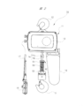
- FIG. 1 is a front view showing an example of an electric chain block to which the present invention is applied.
- FIG. 2 is a right side view of the electric chain block shown in FIG.
- FIG. 3 is a cross-sectional view of the electric chain block shown in FIG.
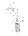
- FIG. 4 is an enlarged perspective view of the lubricant application mechanism shown in FIG.
- FIG. 5 is an enlarged cross-sectional view of the lubricant application mechanism shown in FIG.
- FIG. 6A is a perspective view of a lubricant applicator to which the present invention is applied
- FIG. 6B is a perspective view showing a state in which the lubricant applicator is mounted on a load chain.
- FIG. 7 is an enlarged cross-sectional view of the lubricant applicator shown in FIG.
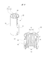
- FIG. 8 is a perspective view showing a modification of the lubricant applicator.
- FIG. 9A is a perspective view showing a modification of the lubricant applicator, and
- FIG. 9B is a perspective view showing another modification of the lubricant applicator.
- the electric chain block 10 has a frame 11 as an electric chain block main body.
- a motor frame 11a is provided on one side of the frame 11, and a gear case 11b is provided on the other side.
- An upper hook, that is, an upper suspending tool 12 is attached to the upper portion of the frame 11, and the electric chain block 10 is suspended by the upper suspending tool 12 at a work location.
- a sprocket 13 is mounted in the frame 11 and below the upper suspension 12 as shown by a broken line in FIG.
- the sprocket 13 is rotatably supported with respect to the frame 11.
- a load chain 14 is hung on the sprocket 13, and a lower hook, that is, a lower suspension 15 is provided at one end of the load chain 14, and a load, that is, a suspended load is hooked on the lower suspension 15. ing. Therefore, in the following description, one end of the load chain 14 provided with the lower suspender 15 may be referred to as “lower end” and the other end may be referred to as “upper end”. However, such a distinction is merely a distinction for convenience of explanation.
- the load chain 14 When the sprocket 13 shown in FIG. 2 is driven to rotate, the load chain 14 is wound up or down. As the load chain 14 is rolled up or down, the suspended load hooked on the lower hanging tool 15 moves upward or moves downward. That is, a suspended load is lifted or hung.
- the frame 11 is attached with a chain container, that is, a chain bucket 16, for accommodating the wound load chain 14. As illustrated in FIG. 2, the chain bucket 16 is offset and attached to the back side of the frame 11.
- the suspended load When the suspended load is lifted, the wound load chain 14 is fed into the chain bucket 16, and when the suspended load is suspended, the load chain 14 is fed out from the chain bucket 16.
- an operation input unit 18 is connected to the electric chain block 10 via a cable 17. The hoisting operation and the lowering operation of the load chain 14 are performed by the operator operating the hoisting switch and the lowering switch provided in the operation input unit 18.
- the sprocket 13 is fixed to a hollow sprocket shaft 21, and this sprocket shaft 21 is rotatably mounted in the frame 11.
- An electric motor 22 is disposed in the motor frame 11 a, and output shafts 23 of the electric motor 22 protrude outward from both end surfaces of the electric motor 22.
- One protruding end 23a of the output shaft 23 is attached to a support plate 24 fixed to the motor frame 11a via a bearing, and an electromagnetic brake 25 is attached to the support plate 24.
- the electromagnetic brake 25 has a coil 26, and a rotating disk 27 is fixed to the protruding end 23a of the output shaft 23 so as to face the support plate 24.
- a fastening disk 28 is disposed between the rotating disk 27 and the coil 26 so as to be movable toward and away from them.
- a spring force in the direction toward the rotating disk 27 is applied to the fastening disk 28.
- the protruding end 23 b of the output shaft 23 of the electric motor 22 is connected to a drive shaft 31 that is rotatably incorporated in the hollow sprocket shaft 21.
- the drive shaft 31 is connected to a small gear 33 via a slip clutch 32 provided in the gear case 11 b, and the small gear 33 meshes with a large gear 35 provided on a reduction shaft 34.
- the small gear 33 and the large gear 35 constitute a speed reduction mechanism 36 that decelerates the rotation of the drive shaft 31 and transmits it to the speed reduction shaft 34.
- the speed reduction shaft 34 is connected to the sprocket shaft 21 via a mechanical brake 37 attached to the outside of the sprocket shaft 21, and the rotation of the output shaft 23 of the electric motor 22 is decelerated by the speed reduction mechanism 36 to the sprocket shaft 21. Communicated.
- the mechanical brake 37 includes a brake disk 40 having a cylindrical threaded portion 38 and a disk portion 39 provided integrally with one end of the threaded portion 38, and the brake disc 40 is fixed to the sprocket shaft 21. ing.
- the mechanical brake 37 exhibits a greater braking torque than the electromagnetic brake 25 that operates by electromagnetic force. Therefore, even if a large load is applied to the sprocket 13 by the suspended load while the electric motor 22 is stopped, the rotation of the sprocket 13 is reliably restricted.
- the slip clutch 32 has a clutch disk 41 attached to the drive shaft 31 and a clutch disk 42 attached to the small gear 33.
- the clutch disks 41 and 42 of the slip clutch 32 slip and the rotation transmission from the small gear 33 to the drive shaft 31 is interrupted. Thereby, lifting of the suspended load exceeding a predetermined weight is prevented.
- a clutch lining is disposed between the clutch disks 41 and 42.
- the external thread 38a is formed in the outer peripheral surface of the thread part 38 of the mechanical brake 37,
- the internal thread 43a of the brake gear 43 is screw-coupled to this external thread 38a.
- the brake gear 43 meshes with a connecting gear 44 provided on the reduction shaft 34, and the output of the drive shaft 31 is transmitted to the brake gear 43 through the reduction shaft 34.
- a ratchet wheel 45 is rotatably mounted between the brake gear 43 and the disk portion 39. When the brake gear 43 relatively rotates in the direction approaching the disc portion 39, the brake gear 43 comes into close contact with the ratchet wheel 45, and the brake disc 40 and the brake gear 43 are fastened via the ratchet wheel 45.
- the mechanical brake 37 having the above-described structure regulates the sprocket shaft 21 from rotating due to the load applied to the sprocket 13 even when the operation of the electric motor 22 is stopped under the state where the suspended load is suspended. .
- the mechanical brake 37 prevents rotation torque in the reverse direction from being transmitted to the electric motor 22 by the suspended load when the suspended load is suspended by the electric motor 22.
- the load chain 14 is formed by a plurality of linked link pieces, and the adjacent link pieces are deviated from each other at right angles.
- the load chain 14 is wound around the sprocket 13 (FIG. 2)
- half of the multiple link pieces constituting the load chain 14 are the vertical first directions that are perpendicular to the rotation center axis of the sprocket 13.
- One link piece 14a is formed, and the other half is a second link piece 14b that faces in the direction along the rotation center axis. That is, the load chain 14 is formed by alternately arranged first link pieces 14a and second link pieces 14b, and the adjacent first link pieces 14a and second link pieces 14b are perpendicular to each other.
- the posture is off.
- first link piece 14a may be referred to as “vertical link piece 14a” and the second link piece 14b may be referred to as “lateral link piece 14b” to be distinguished.
- vertical link piece 14a the first link piece 14a
- lateral link piece 14b the second link piece 14b
- a lower suspension 15 is provided at the lower end of the load chain 14, and a limit (not shown) provided at the lower portion of the frame 11 is disposed on the lower suspension 15.
- An operation unit 50 for operating the switch is provided.
- the operation unit 50 moves up and down together with the lower hanging tool 15 as the load chain 14 is wound up and down.
- the operation unit 50 contacts a limit switch (not shown) provided at the lower part of the frame and pushes up the limit switch.
- the limit switch is pushed up, the power supply to the electric motor 22 (FIG. 3) is cut off regardless of the operation state of the operation input unit 18, and the hoisting operation of the load chain 14 is stopped.
- the operation unit 50 is configured by a coil spring in order to absorb an impact when the operation unit 50 contacts the limit switch. Therefore, in the following description, the operation unit 50 is referred to as “coil spring 50”.
- An upper plate 51 and a lower plate 52 are welded to the upper and lower sides of the coil spring 50, respectively, and the load chain 14 passes through the upper plate 51, the coil spring 50, and the lower plate 52 and is connected to the lower hanging tool 15. Yes.
- a lubricant application mechanism 60 that can move along the load chain 14 is provided on the coil spring 50.
- the lubricant application mechanism 60 includes a lubricant impregnated body 61 (FIG. 5) disposed around the load chain 14 and an exterior body that covers the outer peripheral surface of the lubricant impregnated body 61. 62 and a lid 63 (FIG. 4) that closes one end of the exterior body 62.
- the lubricant impregnated body 61 shown in FIG. 5 is made of a porous material such as sponge or a fiber material such as cloth, and absorbs and holds a lubricant such as lubricating oil or grease.
- the lubricant impregnated body 61 has a substantially cylindrical shape, and a through hole 64 extending along the moving direction of the lubricant application mechanism 60 is formed inside thereof.
- a through-hole 64 through which the load chain 14 passes, that is, penetrates, is formed inside the lubricant-impregnated body 61, and the lubricant-impregnated body 61 can move along the load chain 14.
- the through-hole 64 is formed in a cross shape by a first slit 64a through which the vertical link piece 14a passes and a second slit 64b that intersects the first slit 64a and through which the horizontal link piece 14b passes. Yes. That is, the first slit 64a and the second slit 64b are orthogonal to each other.
- a plurality of protrusions 65 protruding toward the center of the through hole 64 are integrally formed at the intersection of the inner surface of the first slit 64a and the inner surface of the second slit 64b.
- four protrusions 65a, 65b, 65c, and 65d are integrally formed.
- a pair of protrusions 65a and 65b that face each other with the center of the through hole 64 interposed therebetween and another pair of protrusions 65c and 65d that face each other with the center interposed therebetween are integrally formed. That is, four protrusions 65a, 65b, 65c, and 65d are arranged inside the through hole 64 at intervals of 90 degrees.
- the pair of protrusions 65a and 65b are offset by +45 degrees with respect to the vertical link piece 14a and ⁇ 45 degrees with respect to the horizontal link piece 14b.
- the other pair of protrusions 65c and 65d are shifted by ⁇ 45 degrees with respect to the vertical link piece 14a and +45 degrees with respect to the horizontal link piece 14b.
- the + direction is a clockwise direction in the plane of FIG. 5, and the ⁇ direction means a counterclockwise direction.
- each protrusion 65 arranged as described above is in contact with the load chain 14.
- the lubricant impregnated in the lubricant impregnated body 61 is supplied to each protrusion 65 by capillary action. Therefore, the lubricant is applied to the load chain 14 through the protrusions 65. Details regarding lubricant application will be described later.
- the outer peripheral surface of the lubricant-impregnated body 61 is covered with a substantially cylindrical exterior body 62.
- the exterior body 62 is formed of a synthetic resin or cloth and has flexibility. Therefore, the exterior body 62 is deformed when pressed, and the lubricant-impregnated body 61 (FIG. 5) inside the exterior body 62 is crushed along with the deformation. That is, the lubricant impregnated body 61 is elastically deformed by pressing the exterior body 62, and the lubricant impregnated in the lubricant impregnated body 61 can be intentionally supplied to the protrusions 65.
- the contact area between the lubricant-impregnated body 61 including the protrusion 65 and the load chain 14 can be temporarily increased.
- the exterior body 62 returns to the original shape by at least one of the restoring force of the lubricant-impregnated body 61 and its own restoring force.
- the upper opening (not shown) of the exterior body 62 is closed by a disc-shaped lid 63. That is, the upper end surface of the lubricant impregnated body 61 shown in FIG. 5 is covered with the lid 63 shown in FIG.
- the lid 63 is formed with a second through hole 66 through which the load chain 14 passes.
- the through hole 66 has substantially the same shape as the through hole 64 formed in the lubricant-impregnated body 61 and communicates with the through hole 64. That is, the two through holes 64 and 66 are integrated to form one through part.
- the lubricant application mechanism 60 When applying the lubricant to the load chain 14 by the lubricant application mechanism 60 shown in FIG. 1 and the like, the lubricant application mechanism 60 is moved along the load chain 14 by the operator. When the lubricant application mechanism 60 is moved along the load chain 14, the tip of the protrusion 65 provided on the lubricant impregnated body 61 shown in FIG. 5 moves while being in sliding contact with the load chain 14. That is, the tip of the protrusion 65 slides on the load chain 14, and thereby the lubricant is applied to the load chain 14.
- the lubricant is provided at or near the frictional contact portion between the vertical link piece 14a and the horizontal link piece 14b. Is effectively applied.
- a ladder or an elevator car is used as necessary.
- the lubricating oil application mechanism 60 can also be attached to the lower part of the center frame 11. In the embodiment in which the lubricating oil application mechanism 60 is attached to the lower part of the center frame 11, the lubricating oil application mechanism 60 can apply the lubricating oil to the load chain 14 without moving the lubricating oil application mechanism 60.
- the load chain Lubricating oil is applied to 14.
- the lubricant application mechanism 60 is detachably attached to the lower portion of the housing.
- the lubricant application mechanism 60 is placed on the upper plate 51 of the coil spring 50 when not in use (FIGS. 1 and 4). At this time, the lower opening (not shown) of the exterior body 62 is closed by the upper plate 51 of the coil spring 50. At the same time, the lower end surface of the lubricant-impregnated body 61 shown in FIG. 5 is covered by the upper plate 51 shown in FIG. That is, the upper plate 51 of the coil spring 50 also functions as a bottom plate that closes one end of the exterior body 62.
- the lid 63 shown in FIG. 4 can be opened to supply the lubricant.
- the lid 63 is only placed on the edge of the upper opening of the exterior body 62 and is not fixed. Therefore, when the lid 63 is picked and lifted, the upper opening of the exterior body 62 is opened, the upper end surface of the lubricant impregnated body 61 (FIG. 5) is exposed, and the lubricant can be supplied. But the exterior body 62 and the lid
- the height (H) of the lubricant application mechanism 60 shown in FIG. 1 is 30 mm, and the diameter (D) shown in FIG. 5 is 55 mm.
- a numerical value is an example, and the height (H) and the diameter (D) of the lubricant application mechanism 60 can be changed as appropriate.
- the lubricating oil can be applied to the load chains having different diameters by exchanging the lubricant-impregnated body in accordance with the diameter of the load chain.
- the limit switch is pushed up via the lubricant application mechanism 60 when the winding length of the load chain 14 reaches a predetermined length. .
- the maximum winding length of the load chain 14 is affected by the height (H) of the lubricant application mechanism 60. Therefore, it is preferable to determine the height (H) of the lubricant application mechanism 60 in consideration of the maximum winding length of the load chain 14.
- FIGS. 1 to 5 are also referred to as necessary.
- the same reference numerals as those used in FIG. 1 to FIG. 5 indicate the same or equivalent.
- the part 61 a and the other part 61 b of the lubricant-impregnated body 61 shown in FIG. It is connected.
- a part 61 a of the lubricant-impregnated body 61 including a part of the through hole 64 and another part 61 b of the lubricant-impregnated body 61 including another part of the through hole 64 are the exterior body 62.
- the other part 61 b of the lubricant impregnated body 61 including the other part is rotatably connected by the exterior body 62. That is, the two half cracked portions 61 a and 61 b of the lubricant impregnated body 61 are rotatably connected by the exterior body 62.
- the two half cracks 61a and 61b of the lubricant impregnated body 61 are connected to each other so as to be rotatable, that is, openable and closable. Easy to attach and detach. That is, the lubricant applicator 70 according to the present embodiment can be attached to and detached from the load chain 14 that is hung on the sprocket 13 shown in FIG.
- the end portions 62a and 62b of the exterior body 62 overlap each other.
- the end portions 62a and 62b of the exterior body 62 are formed with insertion holes 71a and 71b that communicate with each other when they overlap each other, and the stopper 72 is press-fitted into the communication insertion holes 71a and 71b.
- the end portions 62a and 62b can be connected and fixed.
- the stopper 72 is pulled out from the insertion holes 71a and 71b to release the connection between the end portions 62a and 62b of the exterior body 62, and the half crack portions 61a and 61b are opened. Good.
- the structure for connecting and fixing the end portions 62a and 62b of the exterior body 62 is not limited to the above structure.
- a locking piece 81 having an engagement hole 80 is integrally formed at the end 62a of the exterior body 62, and an engagement protrusion 82 that engages with the engagement hole 80 is formed at the end 62b.
- Some embodiments are integrally molded.
- the height (H) of the lubricant application mechanism 60 is This affects the maximum winding length of the load chain 14.
- the lubricant applicator 70 can be attached to and detached from the load chain 14 of the electric chain block 10. That is, the lubricant applicator 70 can be removed from the load chain 14 after the lubricant application operation to the load chain 14 is completed. Therefore, the height of the lubricant applicator 70 does not affect the maximum winding length of the load chain 14. Therefore, as shown in FIGS.
- the height (full length) of the lubricant applicator 70 may be expanded in accordance with the width of a general human hand. In this case, the operator can easily grasp the lubricant applicator 70, and improvement in workability of the lubricant application operation can be expected.
- the height (full length) of the lubricant applicator 70 shown in FIG. 9 is 100 mm.
- the lubricant-impregnated body may be formed of a porous soft resin or porous rubber.
- the shape of the through hole formed in the lubricant-impregnated body is not limited to a cross shape, and an arbitrary shape such as a circle, an ellipse, a rectangle, or a polygon can be selected.
- the minimum conditions required for the through hole 64 are only two points that the load chain can be penetrated and that a protruding portion that comes into sliding contact with the penetrating load chain is provided.
- the electric chain block 10 shown in FIG. 1 etc. is used in the state fixed to the work location, the present invention is also applied to the electric chain block moved along the guide rail by the trolley. Can do.
Abstract
The present invention consists of the following: a lubricant application mechanism (60) that applies a lubricant to a load chain (14) that is formed from a large number of connected links (14a, 14b) and is provided with a lifting implement on one end; and an electric chain block provided with said lubricant application mechanism (60). This lubricant application mechanism (60) has the following: a lubricant-impregnated body (61) that encircles the load chain (14) and can move along same; a through-hole (64) that passes through the lubricant-impregnated body (61) in the direction in which the lubricant-impregnated body (61) moves; and protrusions (65) that are provided on the inside of the through-hole (64) and make sliding contact with the load chain (14) when the lubricant-impregnated body (61) moves along the load chain (14). The present invention thus makes it possible to apply lubricant to a load chain (14) more easily and more reliably.
Description
本発明は、吊荷を上下動させるための電気チェーンブロックに関し、特にロードチェーンに潤滑剤を塗布するための技術に関する。
The present invention relates to an electric chain block for vertically moving a suspended load, and more particularly to a technique for applying a lubricant to a load chain.
重量物を上下動させる電気チェーンブロックにはロードチェーンが用いられる。ロードチェーンは、連結された多数の金属製のリンク片によって構成されている。ロードチェーンはスプロケットに掛け回されており、スプロケットが駆動されるとロードチェーンの一端に設けられた吊荷吊り下げ用の下フックが上下動し、吊荷の吊り上げと吊り下ろしが行われる。一方、ロードチェーンの他端はチェーン収納器としてのチェーンバケットに収納される。吊荷を吊り上げるときにはロードチェーンの他端側がチェーンバケットに送り込まれ、吊荷を吊り下ろすときにはロードチェーンがチェーンバケットから繰り出される。
A load chain is used for the electric chain block that moves heavy objects up and down. The load chain is constituted by a large number of linked metal link pieces. The load chain is wound around the sprocket. When the sprocket is driven, the lower hook for hanging the suspended load provided at one end of the load chain moves up and down, and the suspended load is lifted and suspended. On the other hand, the other end of the load chain is stored in a chain bucket as a chain storage device. When the suspended load is lifted, the other end of the load chain is fed into the chain bucket, and when the suspended load is suspended, the load chain is unwound from the chain bucket.
ロードチェーンは、上述のように、連結された多数のリンク片によって構成されており、隣り合うリンク片は吊荷の吊り上げおよび吊り下ろし時に滑り接触する。換言すれば、ロードチェーンのリンク片同士は摩擦接触する。摩擦接触によりリンク片の摩耗が進行するとロードチェーンが破断する虞がある。そこで、リンク片の摩耗を抑制するために、ロードチェーンにはグリースや潤滑油などの潤滑剤が塗布される。潤滑剤をロードチェーンに塗布すると、リンク片の摩耗を抑制することができるだけでなく、ロードチェーンのキンクつまり捩れやもつれの発生を防止することもできる。
As described above, the load chain is constituted by a large number of linked link pieces, and adjacent link pieces are in sliding contact with each other when the suspended load is lifted and hung. In other words, the link pieces of the load chain are in frictional contact with each other. If wear of the link piece proceeds due to frictional contact, the load chain may be broken. Therefore, in order to suppress wear of the link piece, a lubricant such as grease or lubricating oil is applied to the load chain. When the lubricant is applied to the load chain, not only can the wear of the link piece be suppressed, but also the kink of the load chain, that is, the occurrence of twisting and entanglement can be prevented.
そこで、潤滑剤塗布機構を備えた電気チェーンブロックが提案されている。例えば特許文献1には、電気チェーンブロック本体としてのフレームに潤滑剤容器が装着された電気チェーンブロックが記載されている。潤滑剤容器に設けられた潤滑剤吐出口とロードチェーンとの間には、ロードチェーンの移動に伴って回転するブラシが設けられ、このブラシを介して潤滑剤吐出口から吐出される潤滑剤がロードチェーンに塗布される。
Therefore, an electric chain block with a lubricant application mechanism has been proposed. For example, Patent Document 1 describes an electric chain block in which a lubricant container is mounted on a frame as an electric chain block main body. A brush that rotates with the movement of the load chain is provided between the lubricant discharge port provided in the lubricant container and the load chain, and the lubricant discharged from the lubricant discharge port via this brush is Applied to the load chain.
特許文献1に記載されている電気チェーンブロックでは、ロードチェーンに対する潤滑剤の塗布が自動的に行われ、かつ、潤滑剤がむらなくロードチェーンに塗布される。
In the electric chain block described in Patent Document 1, the lubricant is automatically applied to the load chain, and the lubricant is evenly applied to the load chain.
しかし、特許文献1に記載されている電気チェーンブロックでは、潤滑剤容器がフレームにねじ部材によって取り外し可能に装着されている。したがって、潤滑剤の残量が少なくなったときには、潤滑剤容器をフレームから取り外して潤滑剤を補給する必要があった。また、ブラシの保守や交換の際にはフレームを分解する必要があった。
However, in the electric chain block described in Patent Document 1, the lubricant container is detachably attached to the frame by a screw member. Therefore, when the remaining amount of the lubricant is reduced, it is necessary to remove the lubricant container from the frame and supply the lubricant. In addition, it was necessary to disassemble the frame when maintaining or replacing the brush.
本発明の目的は、ロードチェーンへの潤滑剤塗布をより簡易かつ確実に行えるようにすることである。
An object of the present invention is to make it possible to more easily and reliably apply a lubricant to a load chain.
上記課題を解決するために、例えば請求の範囲に記載の構成を採用する。
In order to solve the above problems, for example, the configuration described in the claims is adopted.
本願は上記課題を解決する手段を複数含んでいるが、その一例を挙げるならば、「潤滑剤塗布具は、リンク片を多数連結して形成され、一端に吊具が設けられるロードチェーンに潤滑剤を塗布するための潤滑剤塗布具であって、前記ロードチェーンに着脱可能であり、該ロードチェーンに沿って移動可能な潤滑剤含浸体と、前記潤滑剤含浸体を該潤滑剤含浸体の移動方向に貫通する貫通穴と、貫通穴の内側に設けられ、前記潤滑剤含浸体が前記ロードチェーンに沿って移動する際に該ロードチェーンと摺接する突起部と、を有する。」ことを特徴とする。
The present application includes a plurality of means for solving the above-mentioned problems. For example, “Lubricant applicator is formed by connecting a number of link pieces, and lubricates a load chain provided with a hanging tool at one end. A lubricant applicator for applying a lubricant, which is attachable to and detachable from the load chain, and is movable along the load chain; and the lubricant impregnated body of the lubricant impregnated body of the lubricant impregnated body A through-hole penetrating in the moving direction, and a protrusion provided inside the through-hole and in sliding contact with the load chain when the lubricant-impregnated body moves along the load chain. " And
本発明によれば、ロードチェーンへの潤滑剤塗布をより簡易かつ確実に行えるようになる。
According to the present invention, the lubricant can be applied to the load chain more easily and reliably.
(第1の実施形態)
以下、本発明の第1の実施形態について図面を参照しながら詳細に説明する。ここでは、本発明が適用された電気チェーンブロックの一例について説明する。図1~図3に示されるように、本実施形態に係る電気チェーンブロック10は、電気チェーンブロック本体としてのフレーム11を有している。フレーム11の一方側にはモータフレーム11aが設けられ、他方側にはギヤケース11bが設けられている。このフレーム11の上側部には上フックつまり上吊具12が装着されており、電気チェーンブロック10はこの上吊具12により作業箇所に吊り下げられる。フレーム11内であって上吊具12の下側にはスプロケット13が図2に破線で示されるように装着されている。スプロケット13は、フレーム11に対して回転自在に支持されている。このスプロケット13にはロードチェーン14が掛け回されており、ロードチェーン14の一端には、下フックつまり下吊具15が設けられ、この下吊具15に荷物つまり吊荷が引っ掛けられるようになっている。そこで、以下の説明では、下吊具15が設けられているロードチェーン14の一端を“下端”と呼び、他端を“上端”と呼んで区別する場合がある。もっとも、かかる区別は説明の便宜上の区別に過ぎない。 (First embodiment)
Hereinafter, a first embodiment of the present invention will be described in detail with reference to the drawings. Here, an example of an electric chain block to which the present invention is applied will be described. As shown in FIGS. 1 to 3, theelectric chain block 10 according to this embodiment has a frame 11 as an electric chain block main body. A motor frame 11a is provided on one side of the frame 11, and a gear case 11b is provided on the other side. An upper hook, that is, an upper suspending tool 12 is attached to the upper portion of the frame 11, and the electric chain block 10 is suspended by the upper suspending tool 12 at a work location. A sprocket 13 is mounted in the frame 11 and below the upper suspension 12 as shown by a broken line in FIG. The sprocket 13 is rotatably supported with respect to the frame 11. A load chain 14 is hung on the sprocket 13, and a lower hook, that is, a lower suspension 15 is provided at one end of the load chain 14, and a load, that is, a suspended load is hooked on the lower suspension 15. ing. Therefore, in the following description, one end of the load chain 14 provided with the lower suspender 15 may be referred to as “lower end” and the other end may be referred to as “upper end”. However, such a distinction is merely a distinction for convenience of explanation.
以下、本発明の第1の実施形態について図面を参照しながら詳細に説明する。ここでは、本発明が適用された電気チェーンブロックの一例について説明する。図1~図3に示されるように、本実施形態に係る電気チェーンブロック10は、電気チェーンブロック本体としてのフレーム11を有している。フレーム11の一方側にはモータフレーム11aが設けられ、他方側にはギヤケース11bが設けられている。このフレーム11の上側部には上フックつまり上吊具12が装着されており、電気チェーンブロック10はこの上吊具12により作業箇所に吊り下げられる。フレーム11内であって上吊具12の下側にはスプロケット13が図2に破線で示されるように装着されている。スプロケット13は、フレーム11に対して回転自在に支持されている。このスプロケット13にはロードチェーン14が掛け回されており、ロードチェーン14の一端には、下フックつまり下吊具15が設けられ、この下吊具15に荷物つまり吊荷が引っ掛けられるようになっている。そこで、以下の説明では、下吊具15が設けられているロードチェーン14の一端を“下端”と呼び、他端を“上端”と呼んで区別する場合がある。もっとも、かかる区別は説明の便宜上の区別に過ぎない。 (First embodiment)
Hereinafter, a first embodiment of the present invention will be described in detail with reference to the drawings. Here, an example of an electric chain block to which the present invention is applied will be described. As shown in FIGS. 1 to 3, the
図2に示されるスプロケット13が回転駆動されると、ロードチェーン14が巻き上げられたり、巻き下ろされたりする。ロードチェーン14の巻き上げや巻き下ろしに伴って下吊具15に引っ掛けられた吊荷が上方へ移動したり、下方へ移動したりする。すなわち、吊荷が吊り上げられたり、吊り下ろされたりする。図1および図2に示されるように、フレーム11には巻き上げられたロードチェーン14を収容するためのチェーン収納器つまりチェーンバケット16が取り付けられている。チェーンバケット16は、図2に示されるように、フレーム11の背面側にオフセットされて取り付けられている。吊荷が吊り上げられるときには、巻き上げられたロードチェーン14がチェーンバケット16内に送り込まれ、吊荷が吊り下ろされるときには、チェーンバケット16内からロードチェーン14が繰り出される。図1および図2に示されるように、電気チェーンブロック10には、ケーブル17を介して操作入力部18が接続されている。操作入力部18に設けられた巻上げ用スイッチおよび巻下げ用スイッチが作業者によって操作されることにより、ロードチェーン14の巻上げ動作と巻下げ動作が行われる。
When the sprocket 13 shown in FIG. 2 is driven to rotate, the load chain 14 is wound up or down. As the load chain 14 is rolled up or down, the suspended load hooked on the lower hanging tool 15 moves upward or moves downward. That is, a suspended load is lifted or hung. As shown in FIGS. 1 and 2, the frame 11 is attached with a chain container, that is, a chain bucket 16, for accommodating the wound load chain 14. As illustrated in FIG. 2, the chain bucket 16 is offset and attached to the back side of the frame 11. When the suspended load is lifted, the wound load chain 14 is fed into the chain bucket 16, and when the suspended load is suspended, the load chain 14 is fed out from the chain bucket 16. As shown in FIGS. 1 and 2, an operation input unit 18 is connected to the electric chain block 10 via a cable 17. The hoisting operation and the lowering operation of the load chain 14 are performed by the operator operating the hoisting switch and the lowering switch provided in the operation input unit 18.
図3に示されるように、スプロケット13は中空のスプロケット軸21に固定されており、このスプロケット軸21はフレーム11内に回転自在に装着されている。モータフレーム11a内には電動モータ22が配置されており、電動モータ22の出力軸23は電動モータ22の両端面から外方に突出している。出力軸23の一方の突出端部23aは、モータフレーム11aに固定された支持板24に軸受を介して取り付けられており、この支持板24には電磁ブレーキ25が装着されている。
As shown in FIG. 3, the sprocket 13 is fixed to a hollow sprocket shaft 21, and this sprocket shaft 21 is rotatably mounted in the frame 11. An electric motor 22 is disposed in the motor frame 11 a, and output shafts 23 of the electric motor 22 protrude outward from both end surfaces of the electric motor 22. One protruding end 23a of the output shaft 23 is attached to a support plate 24 fixed to the motor frame 11a via a bearing, and an electromagnetic brake 25 is attached to the support plate 24.
電磁ブレーキ25はコイル26を有し、出力軸23の突出端部23aには支持板24に対向するようにして回転ディスク27が固定されている。また、回転ディスク27とコイル26の間には、これらに対して接近離反移動自在に締結ディスク28が配置されている。締結ディスク28には回転ディスク27に向かう方向のばね力が加えられている。ばね力により締結ディスク28が回転ディスク27に押し付けられると、締結ディスク28と回転ディスク27が支持板24に密着して電磁ブレーキ25は締結状態となり、出力軸23はロックされる。一方、コイル26に通電されると、締結ディスク28が磁力によりばね力に抗して吸引され、締結ディスク28が回転ディスク27から離れ、電磁ブレーキ25は出力軸23の回転を許容する開放状態となる。
The electromagnetic brake 25 has a coil 26, and a rotating disk 27 is fixed to the protruding end 23a of the output shaft 23 so as to face the support plate 24. A fastening disk 28 is disposed between the rotating disk 27 and the coil 26 so as to be movable toward and away from them. A spring force in the direction toward the rotating disk 27 is applied to the fastening disk 28. When the fastening disk 28 is pressed against the rotary disk 27 by the spring force, the fastening disk 28 and the rotary disk 27 are brought into close contact with the support plate 24, and the electromagnetic brake 25 is brought into a fastening state, and the output shaft 23 is locked. On the other hand, when the coil 26 is energized, the fastening disk 28 is attracted against the spring force by the magnetic force, the fastening disk 28 is separated from the rotating disk 27, and the electromagnetic brake 25 is in an open state in which the output shaft 23 is allowed to rotate. Become.
図3に示されるように、電動モータ22の出力軸23の突出端部23bは、中空のスプロケット軸21の内部に回転自在に組み込まれている駆動軸31に連結されている。駆動軸31は、ギヤケース11b内に設けられているスリップクラッチ32を介して小歯車33に連結されており、この小歯車33は減速軸34に設けられた大歯車35と噛み合っている。この小歯車33と大歯車35により駆動軸31の回転を減速して減速軸34に伝達する減速機構36が構成されている。減速軸34は、スプロケット軸21の外側に装着されたメカニカルブレーキ37を介してスプロケット軸21に連結されており、電動モータ22の出力軸23の回転は減速機構36により減速されてスプロケット軸21に伝達される。
As shown in FIG. 3, the protruding end 23 b of the output shaft 23 of the electric motor 22 is connected to a drive shaft 31 that is rotatably incorporated in the hollow sprocket shaft 21. The drive shaft 31 is connected to a small gear 33 via a slip clutch 32 provided in the gear case 11 b, and the small gear 33 meshes with a large gear 35 provided on a reduction shaft 34. The small gear 33 and the large gear 35 constitute a speed reduction mechanism 36 that decelerates the rotation of the drive shaft 31 and transmits it to the speed reduction shaft 34. The speed reduction shaft 34 is connected to the sprocket shaft 21 via a mechanical brake 37 attached to the outside of the sprocket shaft 21, and the rotation of the output shaft 23 of the electric motor 22 is decelerated by the speed reduction mechanism 36 to the sprocket shaft 21. Communicated.
メカニカルブレーキ37は、円筒形状のねじ部38と、このねじ部38の一端部に一体に設けられたディスク部39とを備えたブレーキディスク40を有し、ブレーキディスク40はスプロケット軸21に固定されている。メカニカルブレーキ37は、電磁力により作動する電磁ブレーキ25に比して大きな制動トルクを発揮する。したがって、電動モータ22を停止させた状態で吊荷により大きな負荷がスプロケット13に加わっても、スプロケット13の回転が確実に規制される。
The mechanical brake 37 includes a brake disk 40 having a cylindrical threaded portion 38 and a disk portion 39 provided integrally with one end of the threaded portion 38, and the brake disc 40 is fixed to the sprocket shaft 21. ing. The mechanical brake 37 exhibits a greater braking torque than the electromagnetic brake 25 that operates by electromagnetic force. Therefore, even if a large load is applied to the sprocket 13 by the suspended load while the electric motor 22 is stopped, the rotation of the sprocket 13 is reliably restricted.
スリップクラッチ32は駆動軸31に取り付けられるクラッチディスク41と小歯車33に取り付けられるクラッチディスク42とを有している。過度の負荷がスプロケット13に加わった場合には、スリップクラッチ32のクラッチディスク41,42が滑り、小歯車33から駆動軸31への回転伝達が遮断される。これにより、所定重量を超える吊荷の吊り上げが防止される。なお、クラッチディスク41,42の間にはクラッチライニングが配置されている。
The slip clutch 32 has a clutch disk 41 attached to the drive shaft 31 and a clutch disk 42 attached to the small gear 33. When an excessive load is applied to the sprocket 13, the clutch disks 41 and 42 of the slip clutch 32 slip and the rotation transmission from the small gear 33 to the drive shaft 31 is interrupted. Thereby, lifting of the suspended load exceeding a predetermined weight is prevented. A clutch lining is disposed between the clutch disks 41 and 42.
メカニカルブレーキ37のねじ部38の外周面には雄ねじ38aが形成されており、この雄ねじ38aには、ブレーキ歯車43の雌ねじ43aがねじ結合されている。このブレーキ歯車43は、減速軸34に設けられた連結歯車44に噛み合っており、駆動軸31の出力は減速軸34を介してブレーキ歯車43に伝達される。ブレーキ歯車43とディスク部39との間には、ラチェットホイール45が回転自在に装着されている。ブレーキ歯車43がディスク部39に接近する方向に相対回転すると、ブレーキ歯車43がラチェットホイール45に密着し、ラチェットホイール45を介してブレーキディスク40とブレーキ歯車43が締結される。一方、ブレーキ歯車43がブレーキディスク40に対して締結を解除する方向に相対回転すると、ブレーキディスク40とブレーキ歯車43との締結が解除されて、メカニカルブレーキ37は開放状態となる。このように、ブレーキ歯車43がブレーキディスク40に対して相対回転すると、ブレーキ歯車43はブレーキディスク40に対して締結位置と開放位置との間を軸方向に移動することになる。ブレーキ歯車43がディスク部39から離れる位置は、ストッパ46により規制されるようになっている。
The external thread 38a is formed in the outer peripheral surface of the thread part 38 of the mechanical brake 37, The internal thread 43a of the brake gear 43 is screw-coupled to this external thread 38a. The brake gear 43 meshes with a connecting gear 44 provided on the reduction shaft 34, and the output of the drive shaft 31 is transmitted to the brake gear 43 through the reduction shaft 34. A ratchet wheel 45 is rotatably mounted between the brake gear 43 and the disk portion 39. When the brake gear 43 relatively rotates in the direction approaching the disc portion 39, the brake gear 43 comes into close contact with the ratchet wheel 45, and the brake disc 40 and the brake gear 43 are fastened via the ratchet wheel 45. On the other hand, when the brake gear 43 rotates relative to the brake disc 40 in the direction of releasing the engagement, the engagement between the brake disc 40 and the brake gear 43 is released and the mechanical brake 37 is released. As described above, when the brake gear 43 rotates relative to the brake disk 40, the brake gear 43 moves in the axial direction between the fastening position and the release position with respect to the brake disk 40. The position at which the brake gear 43 is separated from the disk portion 39 is regulated by a stopper 46.
上記のような構造を有するメカニカルブレーキ37は、吊荷が吊り下げられた状態の下で電動モータ22の作動を停止させても、スプロケット13に加わる負荷によってスプロケット軸21が回転するのを規制する。また、メカニカルブレーキ37は、電動モータ22により吊荷を吊り下げる際に、吊荷により電動モータ22に逆転方向の回転トルクが伝達されることを防止する。
The mechanical brake 37 having the above-described structure regulates the sprocket shaft 21 from rotating due to the load applied to the sprocket 13 even when the operation of the electric motor 22 is stopped under the state where the suspended load is suspended. . The mechanical brake 37 prevents rotation torque in the reverse direction from being transmitted to the electric motor 22 by the suspended load when the suspended load is suspended by the electric motor 22.
図1および図2に示されるように、ロードチェーン14は、連結された複数のリンク片により形成されており、隣り合うリンク片は相互に直角方向に姿勢がずれている。ロードチェーン14がスプロケット13(図2)に掛け回された状態の下では、ロードチェーン14を構成する多数のリンク片の半数はスプロケット13の回転中心軸に対して直角方向を向く縦向きの第1のリンク片14aとなり、他の半数は回転中心軸に沿う方向を向く横向きの第2のリンク片14bとなる。すなわち、ロードチェーン14は交互に並ぶ第1のリンク片14aと第2のリンク片14bとにより形成されており、隣接する第1のリンク片14aと第2のリンク片14bは相互に直角方向に姿勢がずれている。そこで、以下の説明では、第1のリンク片14aを“縦リンク片14a”と呼び、第2のリンク片14bを“横リンク片14b”と呼んで区別する場合がある。もっとも、かかる区別は説明の便宜上の区別に過ぎない。
As shown in FIGS. 1 and 2, the load chain 14 is formed by a plurality of linked link pieces, and the adjacent link pieces are deviated from each other at right angles. Under the condition that the load chain 14 is wound around the sprocket 13 (FIG. 2), half of the multiple link pieces constituting the load chain 14 are the vertical first directions that are perpendicular to the rotation center axis of the sprocket 13. One link piece 14a is formed, and the other half is a second link piece 14b that faces in the direction along the rotation center axis. That is, the load chain 14 is formed by alternately arranged first link pieces 14a and second link pieces 14b, and the adjacent first link pieces 14a and second link pieces 14b are perpendicular to each other. The posture is off. Therefore, in the following description, the first link piece 14a may be referred to as “vertical link piece 14a” and the second link piece 14b may be referred to as “lateral link piece 14b” to be distinguished. However, such a distinction is merely a distinction for convenience of explanation.
図1および図2に示されるように、ロードチェーン14の下端には下吊具15が設けられており、下吊具15の上には、フレーム11の下部に設けられている不図示のリミットスイッチを操作するための操作部50が設けられている。操作部50は、ロードチェーン14の巻上げ、巻下ろしに伴って下吊具15と共に昇降する。操作部50は、ロードチェーン14の巻上げ長が所定長に達すると、フレーム下部に設けられている不図示のリミットスイッチに接触し、該リミットスイッチを押し上げる。リミットスイッチが押し上げられると、操作入力部18の操作状況に関わらず電動モータ22(図3)への電力供給が遮断され、ロードチェーン14の巻上げ動作が停止される。本実施形態では、操作部50がリミットスイッチに接触した際の衝撃を吸収すべく、コイルスプリングによって操作部50が構成されている。そこで、以下の説明では、操作部50を“コイルスプリング50”と呼ぶ。
As shown in FIGS. 1 and 2, a lower suspension 15 is provided at the lower end of the load chain 14, and a limit (not shown) provided at the lower portion of the frame 11 is disposed on the lower suspension 15. An operation unit 50 for operating the switch is provided. The operation unit 50 moves up and down together with the lower hanging tool 15 as the load chain 14 is wound up and down. When the winding length of the load chain 14 reaches a predetermined length, the operation unit 50 contacts a limit switch (not shown) provided at the lower part of the frame and pushes up the limit switch. When the limit switch is pushed up, the power supply to the electric motor 22 (FIG. 3) is cut off regardless of the operation state of the operation input unit 18, and the hoisting operation of the load chain 14 is stopped. In the present embodiment, the operation unit 50 is configured by a coil spring in order to absorb an impact when the operation unit 50 contacts the limit switch. Therefore, in the following description, the operation unit 50 is referred to as “coil spring 50”.
コイルスプリング50の上下には、それぞれ上プレート51と下プレート52とが溶接されており、ロードチェーン14は上プレート51、コイルスプリング50および下プレート52を貫通して下吊具15に連結されている。
An upper plate 51 and a lower plate 52 are welded to the upper and lower sides of the coil spring 50, respectively, and the load chain 14 passes through the upper plate 51, the coil spring 50, and the lower plate 52 and is connected to the lower hanging tool 15. Yes.
図4に示されるように、コイルスプリング50の上にはロードチェーン14に沿って移動可能な潤滑剤塗布機構60が設けられている。図4,図5に示されるように、潤滑剤塗布機構60は、ロードチェーン14の周囲に配置される潤滑剤含浸体61(図5)と、潤滑剤含浸体61の外周面を覆う外装体62と、外装体62の一端を閉塞する蓋63(図4)とを有する。
As shown in FIG. 4, a lubricant application mechanism 60 that can move along the load chain 14 is provided on the coil spring 50. As shown in FIGS. 4 and 5, the lubricant application mechanism 60 includes a lubricant impregnated body 61 (FIG. 5) disposed around the load chain 14 and an exterior body that covers the outer peripheral surface of the lubricant impregnated body 61. 62 and a lid 63 (FIG. 4) that closes one end of the exterior body 62.
図5に示される潤滑剤含浸体61は、スポンジなどの多孔質材料や布などの繊維材料などからなり、潤滑油やグリースなどの潤滑剤を吸収し、保持する。潤滑剤含浸体61は略円柱状であり、その内側には、潤滑剤塗布機構60の移動方向に沿って延びる貫通穴64が形成されている。換言すれば、潤滑剤含浸体61の内側には、ロードチェーン14が通過すなわち貫通する貫通穴64が形成されており、潤滑剤含浸体61はロードチェーン14に沿って移動可能となっている。この貫通穴64は、縦リンク片14aが通過する第1のスリット64aと、第1のスリット64aと交差し、横リンク片14bが通過する第2のスリット64bとにより、十字形に形成されている。すなわち、第1のスリット64aと第2のスリット64bは直交している。
The lubricant impregnated body 61 shown in FIG. 5 is made of a porous material such as sponge or a fiber material such as cloth, and absorbs and holds a lubricant such as lubricating oil or grease. The lubricant impregnated body 61 has a substantially cylindrical shape, and a through hole 64 extending along the moving direction of the lubricant application mechanism 60 is formed inside thereof. In other words, a through-hole 64 through which the load chain 14 passes, that is, penetrates, is formed inside the lubricant-impregnated body 61, and the lubricant-impregnated body 61 can move along the load chain 14. The through-hole 64 is formed in a cross shape by a first slit 64a through which the vertical link piece 14a passes and a second slit 64b that intersects the first slit 64a and through which the horizontal link piece 14b passes. Yes. That is, the first slit 64a and the second slit 64b are orthogonal to each other.
第1のスリット64aの内側面と第2のスリット64bの内側面との交点には、貫通穴64の中心に向かって突出する複数の突起部65が一体成形されている。本実施形態では4つの突起部65a,65b,65c,65dが一体成形されている。具体的には、貫通穴64の中心を挟んで対向する一対の突起部65a,65bと、同中心を挟んで対向する他の一対の突起部65c,65dが一体成形されている。すなわち、貫通穴64の内側には4つの突起部65a,65b,65c,65dが90度間隔で配置されている。換言すれば、一対の突起部65a,65bは、縦リンク片14aに対して+45度、横リンク片14bに対して-45度ずれている。一方、他の一対の突起部65c,65dは、縦リンク片14aに対して-45度、横リンク片14bに対して+45度ずれている。ここで、+方向とは図5の紙面中における右回りの方向であり、-方向とは左周りの方向を意味する。
A plurality of protrusions 65 protruding toward the center of the through hole 64 are integrally formed at the intersection of the inner surface of the first slit 64a and the inner surface of the second slit 64b. In the present embodiment, four protrusions 65a, 65b, 65c, and 65d are integrally formed. Specifically, a pair of protrusions 65a and 65b that face each other with the center of the through hole 64 interposed therebetween and another pair of protrusions 65c and 65d that face each other with the center interposed therebetween are integrally formed. That is, four protrusions 65a, 65b, 65c, and 65d are arranged inside the through hole 64 at intervals of 90 degrees. In other words, the pair of protrusions 65a and 65b are offset by +45 degrees with respect to the vertical link piece 14a and −45 degrees with respect to the horizontal link piece 14b. On the other hand, the other pair of protrusions 65c and 65d are shifted by −45 degrees with respect to the vertical link piece 14a and +45 degrees with respect to the horizontal link piece 14b. Here, the + direction is a clockwise direction in the plane of FIG. 5, and the − direction means a counterclockwise direction.
上記のように配置されているそれぞれの突起部65の先端はロードチェーン14に接触している。一方、潤滑剤含浸体61に含侵されている潤滑剤は、毛細管現象によってそれぞれの突起部65に供給される。よって、各突起部65を介してロードチェーン14に潤滑剤が塗布される。潤滑剤塗布に関する詳細については後述する。
The tip of each protrusion 65 arranged as described above is in contact with the load chain 14. On the other hand, the lubricant impregnated in the lubricant impregnated body 61 is supplied to each protrusion 65 by capillary action. Therefore, the lubricant is applied to the load chain 14 through the protrusions 65. Details regarding lubricant application will be described later.
図4,図5に示されるように、潤滑剤含浸体61の外周面は略円筒状の外装体62によって覆われている。外装体62は、合成樹脂や布などによって形成されており、可撓性を備えている。よって、外装体62は押圧されると変形し、この変形に伴って外装体62の内側にある潤滑剤含浸体61(図5)が押し潰される。すなわち、外装体62を押圧することにより潤滑剤含浸体61を弾性変形させ、潤滑剤含浸体61に含侵されている潤滑剤を意図的に突起部65に供給することができる。また、突起部65を含む潤滑剤含浸体61とロードチェーン14との接触面積を一時的に増大させることもできる。なお、外装体62に対する押圧が解除されると、外装体62は、潤滑剤含浸体61の復元力と自己の復元力の少なくとも一方によって元の形状に復帰する。
As shown in FIGS. 4 and 5, the outer peripheral surface of the lubricant-impregnated body 61 is covered with a substantially cylindrical exterior body 62. The exterior body 62 is formed of a synthetic resin or cloth and has flexibility. Therefore, the exterior body 62 is deformed when pressed, and the lubricant-impregnated body 61 (FIG. 5) inside the exterior body 62 is crushed along with the deformation. That is, the lubricant impregnated body 61 is elastically deformed by pressing the exterior body 62, and the lubricant impregnated in the lubricant impregnated body 61 can be intentionally supplied to the protrusions 65. Further, the contact area between the lubricant-impregnated body 61 including the protrusion 65 and the load chain 14 can be temporarily increased. When the pressure on the exterior body 62 is released, the exterior body 62 returns to the original shape by at least one of the restoring force of the lubricant-impregnated body 61 and its own restoring force.
図4に示されるように、外装体62の上方開口部(不図示)は円板状の蓋63によって閉塞されている。すなわち、図5に示される潤滑剤含浸体61の上端面は、図4に示される蓋63によって覆われている。この蓋63には、ロードチェーン14が貫通する第2の貫通穴66が形成されている。この貫通穴66は、潤滑剤含浸体61に形成されている貫通穴64と略同一の形状を有し、貫通穴64と連通している。すなわち、2つの貫通穴64,66は一体となって1つの貫通部を形成している。
As shown in FIG. 4, the upper opening (not shown) of the exterior body 62 is closed by a disc-shaped lid 63. That is, the upper end surface of the lubricant impregnated body 61 shown in FIG. 5 is covered with the lid 63 shown in FIG. The lid 63 is formed with a second through hole 66 through which the load chain 14 passes. The through hole 66 has substantially the same shape as the through hole 64 formed in the lubricant-impregnated body 61 and communicates with the through hole 64. That is, the two through holes 64 and 66 are integrated to form one through part.
次に、潤滑剤塗布機構60によってロードチェーン14に潤滑剤を塗布する方法について説明する。図1などに示される潤滑剤塗布機構60によってロードチェーン14に潤滑剤を塗布する際には、潤滑剤塗布機構60が作業者によってロードチェーン14に沿って移動される。潤滑剤塗布機構60がロードチェーン14に沿って移動されると、図5に示される潤滑剤含浸体61に設けられている突起部65の先端はロードチェーン14に摺接しながら移動する。すなわち、突起部65の先端がロードチェーン14上を摺動し、これによりロードチェーン14に潤滑剤が塗布される。特に、複数の突起部65がリンク片14a,14bとの関係で上記のように配置されている本実施形態では、縦リンク片14aと横リンク片14bとの摩擦接触部またはその近傍に潤滑剤が効果的に塗布される。なお、潤滑剤塗布機構60をロードチェーン14に沿って移動させる際には、必要に応じて梯子や昇降車が用いられる。また、潤滑油塗布機構60は、センターフレーム11の下部に取り付けることもできる。潤滑油塗布機構60がセンターフレーム11の下部に取り付けられた実施形態では、潤滑油塗布機構60を移動させなくても、潤滑油塗布機構60によってロードチェーン14に潤滑油を塗布することができる。すなわち、作業者によって巻上げ用スイッチおよび巻下げ用スイッチが操作され、ロードチェーン14の巻上げ動作または巻下げ動作が実行されると、ロードチェーン14が潤滑油塗布機構60を通過する度に、ロードチェーン14に潤滑油が塗布される。この場合、潤滑油塗布機構60は、着脱可能に筐体下部に取付けられているものとする。
Next, a method for applying the lubricant to the load chain 14 by the lubricant application mechanism 60 will be described. When applying the lubricant to the load chain 14 by the lubricant application mechanism 60 shown in FIG. 1 and the like, the lubricant application mechanism 60 is moved along the load chain 14 by the operator. When the lubricant application mechanism 60 is moved along the load chain 14, the tip of the protrusion 65 provided on the lubricant impregnated body 61 shown in FIG. 5 moves while being in sliding contact with the load chain 14. That is, the tip of the protrusion 65 slides on the load chain 14, and thereby the lubricant is applied to the load chain 14. In particular, in the present embodiment in which the plurality of protrusions 65 are arranged as described above in relation to the link pieces 14a and 14b, the lubricant is provided at or near the frictional contact portion between the vertical link piece 14a and the horizontal link piece 14b. Is effectively applied. In addition, when moving the lubricant application mechanism 60 along the load chain 14, a ladder or an elevator car is used as necessary. The lubricating oil application mechanism 60 can also be attached to the lower part of the center frame 11. In the embodiment in which the lubricating oil application mechanism 60 is attached to the lower part of the center frame 11, the lubricating oil application mechanism 60 can apply the lubricating oil to the load chain 14 without moving the lubricating oil application mechanism 60. That is, when the hoisting switch and the lowering switch are operated by the operator and the hoisting operation or the lowering operation of the load chain 14 is executed, every time the load chain 14 passes through the lubricant application mechanism 60, the load chain Lubricating oil is applied to 14. In this case, it is assumed that the lubricant application mechanism 60 is detachably attached to the lower portion of the housing.
潤滑剤塗布機構60は、使用されないときには、コイルスプリング50の上プレート51の上に載置される(図1,図4)。このとき、外装体62の下方開口部(不図示)はコイルスプリング50の上プレート51によって塞がれる。同時に、図5に示される潤滑剤含浸体61の下端面は、図4などに示される上プレート51によって覆われる。すなわち、コイルスプリング50の上プレート51は、外装体62の一端を閉塞する底板としても機能する。
The lubricant application mechanism 60 is placed on the upper plate 51 of the coil spring 50 when not in use (FIGS. 1 and 4). At this time, the lower opening (not shown) of the exterior body 62 is closed by the upper plate 51 of the coil spring 50. At the same time, the lower end surface of the lubricant-impregnated body 61 shown in FIG. 5 is covered by the upper plate 51 shown in FIG. That is, the upper plate 51 of the coil spring 50 also functions as a bottom plate that closes one end of the exterior body 62.
また、図5に示される潤滑剤含浸体61に含侵されている潤滑剤の量が減った場合には、図4に示される蓋63を開けて潤滑剤を補給することができる。蓋63は外装体62の上方開口部の縁に載せられているだけであって、固定されていない。よって、蓋63を摘んで持ち上げると、外装体62の上方開口部が開かれ、潤滑剤含浸体61(図5)の上端面が露出し、潤滑剤の補給が可能となる。もっとも、必要に応じて固定を解除することができれば、外装体62と蓋63とが固定されていてもよい。
Further, when the amount of the lubricant impregnated in the lubricant impregnated body 61 shown in FIG. 5 decreases, the lid 63 shown in FIG. 4 can be opened to supply the lubricant. The lid 63 is only placed on the edge of the upper opening of the exterior body 62 and is not fixed. Therefore, when the lid 63 is picked and lifted, the upper opening of the exterior body 62 is opened, the upper end surface of the lubricant impregnated body 61 (FIG. 5) is exposed, and the lubricant can be supplied. But the exterior body 62 and the lid | cover 63 may be fixed as long as fixation can be cancelled | released as needed.
なお、図1に示される潤滑剤塗布機構60の高さ(H)は30mmであり、図5に示される直径(D)は55mmである。もっとも、かかる数値は一例であり、潤滑剤塗布機構60の高さ(H)や直径(D)は適宜変更することができる。これにより、潤滑材含浸体をロードチェーンの径に合わせて交換することで径の異なるロードチェーンへも潤滑油を塗布することができる。ただし、コイルスプリング50の上に潤滑剤塗布機構60が設けられている本実施形態では、ロードチェーン14の巻上げ長が所定長に達すると、潤滑剤塗布機構60を介して上記リミットスイッチが押し上げられる。換言すれば、ロードチェーン14の最大巻上げ長は、潤滑剤塗布機構60の高さ(H)に影響を受ける。そこで、ロードチェーン14の最大巻上げ長を考慮した上で潤滑剤塗布機構60の高さ(H)を決定することが好ましい。
The height (H) of the lubricant application mechanism 60 shown in FIG. 1 is 30 mm, and the diameter (D) shown in FIG. 5 is 55 mm. However, such a numerical value is an example, and the height (H) and the diameter (D) of the lubricant application mechanism 60 can be changed as appropriate. Accordingly, the lubricating oil can be applied to the load chains having different diameters by exchanging the lubricant-impregnated body in accordance with the diameter of the load chain. However, in the present embodiment in which the lubricant application mechanism 60 is provided on the coil spring 50, the limit switch is pushed up via the lubricant application mechanism 60 when the winding length of the load chain 14 reaches a predetermined length. . In other words, the maximum winding length of the load chain 14 is affected by the height (H) of the lubricant application mechanism 60. Therefore, it is preferable to determine the height (H) of the lubricant application mechanism 60 in consideration of the maximum winding length of the load chain 14.
(第2の実施形態)
以下、本発明の第2の実施形態について図面を参照しながら詳細に説明する。ここでは、本発明が適用された潤滑剤塗布具の一例について図6を参照しながら説明する。もっとも、本実施形態に係る潤滑剤塗布具は、図1や図2などに示される電気チェーンブロック10のロードチェーン14に着脱可能であり、ロードチェーン14に装着された際には、既に説明した潤滑剤塗布機構60と実質的に同一の潤滑剤塗布機構を構成する。そこで、潤滑剤塗布機構60と共通する構成についての説明は適宜省略する。また、以下の説明では必要に応じて図1~図5も参照する。なお、以下の説明で参照する図6中で用いられている符号のうち、図1~図5中で用いられている符号と同一の符号は、同一物または相当物を示す。 (Second Embodiment)
Hereinafter, a second embodiment of the present invention will be described in detail with reference to the drawings. Here, an example of a lubricant applicator to which the present invention is applied will be described with reference to FIG. However, the lubricant applicator according to the present embodiment can be attached to and detached from theload chain 14 of the electric chain block 10 shown in FIGS. 1 and 2, and has already been described when attached to the load chain 14. The lubricant application mechanism is substantially the same as the lubricant application mechanism 60. Therefore, description of the configuration common to the lubricant application mechanism 60 is omitted as appropriate. In the following description, FIGS. 1 to 5 are also referred to as necessary. Of the reference numerals used in FIG. 6 referred to in the following description, the same reference numerals as those used in FIG. 1 to FIG. 5 indicate the same or equivalent.
以下、本発明の第2の実施形態について図面を参照しながら詳細に説明する。ここでは、本発明が適用された潤滑剤塗布具の一例について図6を参照しながら説明する。もっとも、本実施形態に係る潤滑剤塗布具は、図1や図2などに示される電気チェーンブロック10のロードチェーン14に着脱可能であり、ロードチェーン14に装着された際には、既に説明した潤滑剤塗布機構60と実質的に同一の潤滑剤塗布機構を構成する。そこで、潤滑剤塗布機構60と共通する構成についての説明は適宜省略する。また、以下の説明では必要に応じて図1~図5も参照する。なお、以下の説明で参照する図6中で用いられている符号のうち、図1~図5中で用いられている符号と同一の符号は、同一物または相当物を示す。 (Second Embodiment)
Hereinafter, a second embodiment of the present invention will be described in detail with reference to the drawings. Here, an example of a lubricant applicator to which the present invention is applied will be described with reference to FIG. However, the lubricant applicator according to the present embodiment can be attached to and detached from the
図6に示されるように、本実施形態に係る潤滑剤塗布具70では、図5に示される潤滑剤含浸体61の一部61aと他の一部61bとが外装体62によって回動可能に連結されている。具体的には、貫通穴64の一部を含む潤滑剤含浸体61の一部61aと、貫通穴64の他の一部を含む潤滑剤含浸体61の他の一部61bとが外装体62によって回動可能に連結されている。より具体的には、図5に示される第1のスリット64aおよび第2のスリット64bの一部を含む潤滑剤含浸体61の一部61aと、第1のスリット64aおよび第2のスリット64bの他の一部を含む潤滑剤含浸体61の他の一部61bとが外装体62によって回動可能に連結されている。すなわち、潤滑剤含浸体61の2つの半割れ部61a,61bが外装体62によって回動可能に連結されている。
As shown in FIG. 6, in the lubricant applicator 70 according to the present embodiment, the part 61 a and the other part 61 b of the lubricant-impregnated body 61 shown in FIG. It is connected. Specifically, a part 61 a of the lubricant-impregnated body 61 including a part of the through hole 64 and another part 61 b of the lubricant-impregnated body 61 including another part of the through hole 64 are the exterior body 62. Are pivotally connected. More specifically, a part 61a of the lubricant impregnated body 61 including parts of the first slit 64a and the second slit 64b shown in FIG. 5, and the first slit 64a and the second slit 64b. The other part 61 b of the lubricant impregnated body 61 including the other part is rotatably connected by the exterior body 62. That is, the two half cracked portions 61 a and 61 b of the lubricant impregnated body 61 are rotatably connected by the exterior body 62.
したがって、図7に示されるように、2つの半割れ部61a,61bを突き合わせると、一方の半割れ部61aに形成されている第1のスリット64aおよび第2のスリット64bの一部と、他方の半割れ部61bに形成されている第1のスリット64aおよび第2のスリット64bの他の一部とが突き合わされて貫通穴64が形成される。
Therefore, as shown in FIG. 7, when the two half cracks 61a and 61b are abutted, a part of the first slit 64a and the second slit 64b formed in one half crack 61a, The first slit 64a and the other part of the second slit 64b formed in the other half cracked portion 61b are abutted with each other to form the through hole 64.
上記のように、本実施形態に係る潤滑剤塗布具70では、潤滑剤含浸体61の2つの半割れ部61a,61bが回動可能、つまり開閉可能に連結されており、ロードチェーン14への着脱が容易となっている。すなわち、本実施形態に係る潤滑剤塗布具70は、図2などに示されるスプロケット13に掛け回されている状態のロードチェーン14にそのまま着脱することができる。
As described above, in the lubricant applicator 70 according to the present embodiment, the two half cracks 61a and 61b of the lubricant impregnated body 61 are connected to each other so as to be rotatable, that is, openable and closable. Easy to attach and detach. That is, the lubricant applicator 70 according to the present embodiment can be attached to and detached from the load chain 14 that is hung on the sprocket 13 shown in FIG.
なお、図6に示されるように、2つの半割れ部61a,61bが突き合わされると、外装体62の端部62a,62bが重なり合う。外装体62の端部62a,62bには、これらが重なり合ったときに互いに連通する差込穴71a,71bが形成されており、連通した差込穴71a,71bに止め具72を圧入することにより端部62a,62bを連結し、固定することができる。潤滑剤塗布具70をロードチェーン14から取り外すときには、止め具72を差込穴71a,71bから引き抜いて外装体62の端部62a,62bの連結を解除し、半割れ部61a,61bを開けばよい。
In addition, as shown in FIG. 6, when the two half-cracked portions 61a and 61b are abutted, the end portions 62a and 62b of the exterior body 62 overlap each other. The end portions 62a and 62b of the exterior body 62 are formed with insertion holes 71a and 71b that communicate with each other when they overlap each other, and the stopper 72 is press-fitted into the communication insertion holes 71a and 71b. The end portions 62a and 62b can be connected and fixed. When the lubricant applicator 70 is removed from the load chain 14, the stopper 72 is pulled out from the insertion holes 71a and 71b to release the connection between the end portions 62a and 62b of the exterior body 62, and the half crack portions 61a and 61b are opened. Good.
もっとも、外装体62の端部62a,62bを連結し、固定するための構造は上記構造に限定されなない。例えば、図8に示すように、外装体62の端部62aに係合穴80を備えた係止片81が一体成形され、端部62bに係合穴80に係合する係合突起82が一体成形された実施形態もある。
However, the structure for connecting and fixing the end portions 62a and 62b of the exterior body 62 is not limited to the above structure. For example, as shown in FIG. 8, a locking piece 81 having an engagement hole 80 is integrally formed at the end 62a of the exterior body 62, and an engagement protrusion 82 that engages with the engagement hole 80 is formed at the end 62b. Some embodiments are integrally molded.
なお、潤滑剤塗布機構60がコイルスプリング50の上に常設されている第1の実施形態に係る電気チェーンブロック10(図1,図2)では、潤滑剤塗布機構60の高さ(H)がロードチェーン14の最大巻上げ長に影響する。一方、潤滑剤塗布具70は、電気チェーンブロック10のロードチェーン14に着脱可能である。すなわち、潤滑剤塗布具70は、ロードチェーン14への潤滑剤塗布作業が終了した後はロードチェーン14から取り外すことができる。よって、潤滑剤塗布具70の高さがロードチェーン14の最大巻上げ長に影響することはない。そこで、図9(a),(b)に示されるように、潤滑剤塗布具70の高さ(全長)を一般的な人の手の幅に合わせて拡張してもよい。この場合、作業者が潤滑剤塗布具70を握り易くなり、潤滑剤塗布作業の作業性向上が期待できる。なお、図9に示されている潤滑剤塗布具70の高さ(全長)は、100mmである。
In the electric chain block 10 (FIGS. 1 and 2) according to the first embodiment in which the lubricant application mechanism 60 is permanently installed on the coil spring 50, the height (H) of the lubricant application mechanism 60 is This affects the maximum winding length of the load chain 14. On the other hand, the lubricant applicator 70 can be attached to and detached from the load chain 14 of the electric chain block 10. That is, the lubricant applicator 70 can be removed from the load chain 14 after the lubricant application operation to the load chain 14 is completed. Therefore, the height of the lubricant applicator 70 does not affect the maximum winding length of the load chain 14. Therefore, as shown in FIGS. 9A and 9B, the height (full length) of the lubricant applicator 70 may be expanded in accordance with the width of a general human hand. In this case, the operator can easily grasp the lubricant applicator 70, and improvement in workability of the lubricant application operation can be expected. In addition, the height (full length) of the lubricant applicator 70 shown in FIG. 9 is 100 mm.
本発明は前記実施の形態に限定されるものではなく、その要旨を逸脱しない範囲で種々変更可能である。例えば、多孔質の軟質性樹脂や多孔質性ゴムによって潤滑剤含浸体を形成してもよい。また、潤滑剤含浸体に形成される貫通穴の形状は十字形に限定されず、円形、楕円形、矩形、多角形などの任意の形状を選択することができる。貫通穴64に要求される最低限の条件は、ロードチェーンが貫通可能であることと、貫通するロードチェーンと摺接する突起部が設けられていることの二点のみである。さらに、図1などに示される電気チェーンブロック10は作業箇所に固定された状態で使用されるものであるが、トロリによりガイドレールに沿って移動される電気チェーンブロックにも本発明を適用することができる。
The present invention is not limited to the embodiment described above, and various modifications can be made without departing from the scope of the invention. For example, the lubricant-impregnated body may be formed of a porous soft resin or porous rubber. The shape of the through hole formed in the lubricant-impregnated body is not limited to a cross shape, and an arbitrary shape such as a circle, an ellipse, a rectangle, or a polygon can be selected. The minimum conditions required for the through hole 64 are only two points that the load chain can be penetrated and that a protruding portion that comes into sliding contact with the penetrating load chain is provided. Furthermore, although the electric chain block 10 shown in FIG. 1 etc. is used in the state fixed to the work location, the present invention is also applied to the electric chain block moved along the guide rail by the trolley. Can do.
Claims (13)
- 連結された複数のリンク片によって形成され、一端に吊具が設けられるロードチェーンに潤滑剤を塗布するための潤滑剤塗布具であって、
前記ロードチェーンに着脱可能であり、該ロードチェーンに沿って移動可能な潤滑剤含浸体と、
前記潤滑剤含浸体を該潤滑剤含浸体の移動方向に貫通する貫通穴と、
前記貫通穴の内側に設けられ、前記潤滑剤含浸体が前記ロードチェーンに沿って移動する際に該ロードチェーンと摺接する突起部と、を有する、潤滑剤塗布具。 A lubricant applicator for applying a lubricant to a load chain formed by a plurality of connected link pieces and provided with a hanging tool at one end,
A lubricant-impregnated body detachably attached to the load chain and movable along the load chain;
A through-hole penetrating the lubricant-impregnated body in the moving direction of the lubricant-impregnated body,
A lubricant applicator, which is provided inside the through hole, and has a protrusion that comes into sliding contact with the load chain when the lubricant-impregnated body moves along the load chain. - 請求項1に記載の潤滑剤塗布具であって、
前記貫通穴は、第1のリンク片が通過する第1のスリットと、該第1のスリットと交差し、前記第1のリンク片に隣接する第2のリンク片が通過する第2のスリットと、により形成される、潤滑剤塗布具。 The lubricant applicator according to claim 1,
The through hole includes a first slit through which the first link piece passes, and a second slit through which the second link piece that intersects the first slit and is adjacent to the first link piece passes. A lubricant applicator formed by - 請求項2に記載の潤滑剤塗布具であって、
前記第1のスリットと前記第2のスリットが直交している、潤滑剤塗布具。 The lubricant applicator according to claim 2,
The lubricant applicator, wherein the first slit and the second slit are orthogonal to each other. - 請求項2または3に記載の潤滑剤塗布具であって、
前記第1のスリットの内側面と前記第2のスリットの内側面との交点に前記突起部が設けられている、潤滑剤塗布具。 The lubricant applicator according to claim 2 or 3,
The lubricant applicator, wherein the protrusion is provided at an intersection between the inner surface of the first slit and the inner surface of the second slit. - 請求項1~4のいずれかに記載の潤滑剤塗布具であって、
前記潤滑剤含浸体の少なくとも一部を覆う可撓性を備えた外装体を有する、潤滑剤塗布具。 The lubricant applicator according to any one of claims 1 to 4,
A lubricant applicator comprising a flexible exterior body covering at least a part of the lubricant-impregnated body. - 請求項5に記載の潤滑剤塗布具であって、
前記貫通穴の一部を含む前記潤滑剤含浸体の一部と、前記貫通穴の他の一部を含む前記潤滑剤含浸体の他の一部とが前記外装体を介して開閉可能に連結されている、潤滑剤塗布具。 The lubricant applicator according to claim 5,
A part of the lubricant-impregnated body including a part of the through-hole and a part of the lubricant-impregnated body including another part of the through-hole are connected to be opened and closed via the exterior body. A lubricant applicator. - 請求項1~6のいずれかに記載の潤滑剤塗布具であって、
前記潤滑材含浸体が前記ロードチェーンの径に合わせて交換可能である、潤滑剤塗布具。 The lubricant applicator according to any one of claims 1 to 6,
The lubricant applicator, wherein the lubricant-impregnated body is replaceable according to the diameter of the load chain. - 連結された複数のリンク片によって形成され、一端に吊具が設けられるロードチェーンに潤滑剤を塗布する潤滑剤塗布機構を備えた電気チェーンブロックであって、
前記潤滑剤塗布機構は、
前記ロードチェーンの周囲に配置され、該ロードチェーンに沿って移動可能な潤滑剤含浸体と、
前記潤滑剤含浸体を該潤滑剤含浸体の移動方向に貫通する貫通穴と、
前記貫通穴の内側に設けられ、前記ロードチェーンと摺接する突起部と、を有する、電気チェーンブロック。 An electric chain block including a lubricant application mechanism for applying a lubricant to a load chain formed by a plurality of linked pieces and provided with a hanging tool at one end,
The lubricant application mechanism is
A lubricant impregnated body disposed around the load chain and movable along the load chain;
A through-hole penetrating the lubricant-impregnated body in the moving direction of the lubricant-impregnated body,
An electric chain block having a protrusion provided inside the through hole and in sliding contact with the load chain. - 請求項8に記載の電気チェーンブロックであって、
前記貫通穴は、第1のリンク片が通過する第1のスリットと、該第1のスリットと交差し、前記第1のリンク片に隣接する第2のリンク片が通過する第2のスリットと、により形成される、電気チェーンブロック。 The electric chain block according to claim 8,
The through hole includes a first slit through which the first link piece passes, and a second slit through which the second link piece that intersects the first slit and is adjacent to the first link piece passes. , Formed by an electric chain block. - 請求項9に記載の電気チェーンブロックであって、
前記第1のスリットと前記第2のスリットとが直交している、電気チェーンブロック。 An electrical chain block according to claim 9,
An electric chain block in which the first slit and the second slit are orthogonal to each other. - 請求項9または10に記載の電気チェーンブロックであって、
前記第1のスリットの内側面と前記第2のスリットの内側面との交点に前記突起部が設けられている、電気チェーンブロック。 The electric chain block according to claim 9 or 10,
An electric chain block in which the protrusion is provided at an intersection of an inner surface of the first slit and an inner surface of the second slit. - 請求項8~11のいずれかに記載の電気チェーンブロックであって、
前記潤滑剤含浸体の少なくとも一部を覆う可撓性を備えた外装体を有する、電気チェーンブロック。 The electric chain block according to any one of claims 8 to 11,
An electric chain block having a flexible exterior body covering at least a part of the lubricant-impregnated body. - 請求項8~12のいずれかに記載の電気チェーンブロックであって、
前記潤滑剤塗布機構は前記電気チェーンブロックの筐体下部に着脱可能に取り付けられ、
前記ロードチェーンが巻上げ動作および巻下げ動作により移動する度に、潤滑剤が前記ロードチェーンに塗布される、電気チェーンブロック。 The electric chain block according to any one of claims 8 to 12,
The lubricant application mechanism is detachably attached to the lower part of the casing of the electric chain block,
An electric chain block in which a lubricant is applied to the load chain each time the load chain moves by a winding operation and a lowering operation.
Priority Applications (2)
| Application Number | Priority Date | Filing Date | Title |
|---|---|---|---|
| CN201380042005.4A CN104540768B (en) | 2012-12-25 | 2013-06-27 | Electric-driven chain block and lubricant applying tool |
| JP2014554175A JP6083765B2 (en) | 2012-12-25 | 2013-06-27 | Electric chain block and lubricant applicator |
Applications Claiming Priority (2)
| Application Number | Priority Date | Filing Date | Title |
|---|---|---|---|
| JP2012280565 | 2012-12-25 | ||
| JP2012-280565 | 2012-12-25 |
Publications (1)
| Publication Number | Publication Date |
|---|---|
| WO2014103408A1 true WO2014103408A1 (en) | 2014-07-03 |
Family
ID=51020516
Family Applications (1)
| Application Number | Title | Priority Date | Filing Date |
|---|---|---|---|
| PCT/JP2013/067669 WO2014103408A1 (en) | 2012-12-25 | 2013-06-27 | Electric chain block and lubricant applicator |
Country Status (3)
| Country | Link |
|---|---|
| JP (1) | JP6083765B2 (en) |
| CN (1) | CN104540768B (en) |
| WO (1) | WO2014103408A1 (en) |
Citations (6)
| Publication number | Priority date | Publication date | Assignee | Title |
|---|---|---|---|---|
| JPS56166963A (en) * | 1980-05-27 | 1981-12-22 | Kansai Paint Co Ltd | Painting apparatus and method therefor |
| US4448397A (en) * | 1982-11-12 | 1984-05-15 | Columbus Mckinnon Corporation | Pneumatic powered hoist |
| JPS6120597U (en) * | 1984-07-12 | 1986-02-06 | 東京製綱株式会社 | Wire rope oil supply device |
| JPH06198235A (en) * | 1992-08-05 | 1994-07-19 | Honsyu Shikoku Renrakukiyou Kodan | Tool for treating outer surface of wire rope |
| US20060043043A1 (en) * | 2004-09-01 | 2006-03-02 | Zinter Handling, Inc. | Clean room crane assembly |
| JP2010149942A (en) * | 2008-12-24 | 2010-07-08 | Hitachi Industrial Equipment Systems Co Ltd | Electric chain block |
-
2013
- 2013-06-27 WO PCT/JP2013/067669 patent/WO2014103408A1/en active Application Filing
- 2013-06-27 JP JP2014554175A patent/JP6083765B2/en active Active
- 2013-06-27 CN CN201380042005.4A patent/CN104540768B/en active Active
Patent Citations (7)
| Publication number | Priority date | Publication date | Assignee | Title |
|---|---|---|---|---|
| JPS56166963A (en) * | 1980-05-27 | 1981-12-22 | Kansai Paint Co Ltd | Painting apparatus and method therefor |
| JPH0138541B2 (en) * | 1980-05-27 | 1989-08-15 | Kansai Paint Co Ltd | |
| US4448397A (en) * | 1982-11-12 | 1984-05-15 | Columbus Mckinnon Corporation | Pneumatic powered hoist |
| JPS6120597U (en) * | 1984-07-12 | 1986-02-06 | 東京製綱株式会社 | Wire rope oil supply device |
| JPH06198235A (en) * | 1992-08-05 | 1994-07-19 | Honsyu Shikoku Renrakukiyou Kodan | Tool for treating outer surface of wire rope |
| US20060043043A1 (en) * | 2004-09-01 | 2006-03-02 | Zinter Handling, Inc. | Clean room crane assembly |
| JP2010149942A (en) * | 2008-12-24 | 2010-07-08 | Hitachi Industrial Equipment Systems Co Ltd | Electric chain block |
Also Published As
| Publication number | Publication date |
|---|---|
| JPWO2014103408A1 (en) | 2017-01-12 |
| CN104540768B (en) | 2017-03-29 |
| CN104540768A (en) | 2015-04-22 |
| JP6083765B2 (en) | 2017-02-22 |
Similar Documents
| Publication | Publication Date | Title |
|---|---|---|
| JP5383638B2 (en) | Electric chain block | |
| KR101450624B1 (en) | Trolley | |
| JP2012001351A (en) | Driving sheave and elevator | |
| JP6083765B2 (en) | Electric chain block and lubricant applicator | |
| KR101085827B1 (en) | Friction wheel hoist with free fall function | |
| JP2011102182A (en) | Mechanical brake device for hoisting machine | |
| CN201538630U (en) | Drive device of elevator | |
| KR101849953B1 (en) | Hoist without reducer | |
| CN202251857U (en) | Exhaust mechanism of gear box | |
| KR102115587B1 (en) | Two drum hoist | |
| KR20080076062A (en) | Prevent folling carriage apparatus of hoist | |
| KR101559685B1 (en) | Caterpillar with clutch for moving cable | |
| CN203006827U (en) | Electromagnetic braking device | |
| JP6467333B2 (en) | Chain block and built-in cover | |
| JP6961558B2 (en) | Electric chain block and spring guide used for it | |
| JP4408239B2 (en) | Electromagnetic disc brake and elevator hoisting machine equipped with the same | |
| KR20160044087A (en) | Chain block | |
| CN110040647A (en) | A kind of reel braking pipe mover | |
| JP6491906B2 (en) | Chain mounting aid and electric chain block | |
| JP7362542B2 (en) | Electric hoisting device | |
| CN215666500U (en) | Pin shaft coupling elevator host | |
| CN201647775U (en) | Elevator traction machine | |
| CN201545581U (en) | Elevator traction machine | |
| WO2006011214A1 (en) | Hoist for elevator | |
| JP2008213991A (en) | Frictional contact-conditioning device for elevator braking device |
Legal Events
| Date | Code | Title | Description |
|---|---|---|---|
| 121 | Ep: the epo has been informed by wipo that ep was designated in this application |
Ref document number: 13868164 Country of ref document: EP Kind code of ref document: A1 |
|
| NENP | Non-entry into the national phase |
Ref country code: DE |
|
| ENP | Entry into the national phase |
Ref document number: 2014554175 Country of ref document: JP Kind code of ref document: A |
|
| 122 | Ep: pct application non-entry in european phase |
Ref document number: 13868164 Country of ref document: EP Kind code of ref document: A1 |