WO2014098030A1 - 無線通信端末機 - Google Patents
無線通信端末機 Download PDFInfo
- Publication number
- WO2014098030A1 WO2014098030A1 PCT/JP2013/083630 JP2013083630W WO2014098030A1 WO 2014098030 A1 WO2014098030 A1 WO 2014098030A1 JP 2013083630 W JP2013083630 W JP 2013083630W WO 2014098030 A1 WO2014098030 A1 WO 2014098030A1
- Authority
- WO
- WIPO (PCT)
- Prior art keywords
- lid
- electrodes
- pair
- antenna
- wireless communication
- Prior art date
- Legal status (The legal status is an assumption and is not a legal conclusion. Google has not performed a legal analysis and makes no representation as to the accuracy of the status listed.)
- Ceased
Links
Images




Classifications
-
- H—ELECTRICITY
- H04—ELECTRIC COMMUNICATION TECHNIQUE
- H04B—TRANSMISSION
- H04B1/00—Details of transmission systems, not covered by a single one of groups H04B3/00 - H04B13/00; Details of transmission systems not characterised by the medium used for transmission
- H04B1/38—Transceivers, i.e. devices in which transmitter and receiver form a structural unit and in which at least one part is used for functions of transmitting and receiving
- H04B1/3827—Portable transceivers
- H04B1/3888—Arrangements for carrying or protecting transceivers
-
- H—ELECTRICITY
- H01—ELECTRIC ELEMENTS
- H01Q—ANTENNAS, i.e. RADIO AERIALS
- H01Q1/00—Details of, or arrangements associated with, antennas
- H01Q1/12—Supports; Mounting means
- H01Q1/22—Supports; Mounting means by structural association with other equipment or articles
- H01Q1/24—Supports; Mounting means by structural association with other equipment or articles with receiving set
- H01Q1/241—Supports; Mounting means by structural association with other equipment or articles with receiving set used in mobile communications, e.g. GSM
- H01Q1/242—Supports; Mounting means by structural association with other equipment or articles with receiving set used in mobile communications, e.g. GSM specially adapted for hand-held use
- H01Q1/243—Supports; Mounting means by structural association with other equipment or articles with receiving set used in mobile communications, e.g. GSM specially adapted for hand-held use with built-in antennas
-
- H—ELECTRICITY
- H01—ELECTRIC ELEMENTS
- H01Q—ANTENNAS, i.e. RADIO AERIALS
- H01Q7/00—Loop antennas with a substantially uniform current distribution around the loop and having a directional radiation pattern in a plane perpendicular to the plane of the loop
-
- H—ELECTRICITY
- H04—ELECTRIC COMMUNICATION TECHNIQUE
- H04M—TELEPHONIC COMMUNICATION
- H04M1/00—Substation equipment, e.g. for use by subscribers
- H04M1/02—Constructional features of telephone sets
- H04M1/0202—Portable telephone sets, e.g. cordless phones, mobile phones or bar type handsets
- H04M1/026—Details of the structure or mounting of specific components
-
- H—ELECTRICITY
- H05—ELECTRIC TECHNIQUES NOT OTHERWISE PROVIDED FOR
- H05K—PRINTED CIRCUITS; CASINGS OR CONSTRUCTIONAL DETAILS OF ELECTRIC APPARATUS; MANUFACTURE OF ASSEMBLAGES OF ELECTRICAL COMPONENTS
- H05K5/00—Casings, cabinets or drawers for electric apparatus
- H05K5/02—Details
- H05K5/0247—Electrical details of casings, e.g. terminals, passages for cables or wiring
-
- H—ELECTRICITY
- H05—ELECTRIC TECHNIQUES NOT OTHERWISE PROVIDED FOR
- H05K—PRINTED CIRCUITS; CASINGS OR CONSTRUCTIONAL DETAILS OF ELECTRIC APPARATUS; MANUFACTURE OF ASSEMBLAGES OF ELECTRICAL COMPONENTS
- H05K5/00—Casings, cabinets or drawers for electric apparatus
- H05K5/10—Casings, cabinets or drawers for electric apparatus comprising several parts forming a closed casing
Definitions
- an antenna for short-range wireless communication may be installed in addition to an antenna for telephone communication.
- an antenna for short-range wireless communication is installed on the lid that closes the battery chamber of the main body containing the electronic component, and a pair of electrodes connected to the antenna is provided on the inner surface of the lid, The main body is provided with a pair of terminals to be in contact with the pair of electrodes.
- the lid In the cellular phone, by attaching the lid to the casing, the pair of electrodes of the lid contacts the pair of terminals of the body, the antenna is connected to the electronic circuit of the body, and the antenna functions. .
- FIGS. 5 and 7 a pair of terminals (11) and (11) are projected from the main body (1).
- the lid (3) By attaching the lid (3) to the housing (2), the tip of each terminal (11) is pressed against the surface of each electrode (41) as shown in FIGS.
- the antenna (4) is connected to an electronic circuit (not shown) built in the main body (1).
- electrodes (41) are provided on the inner surface of the lid (3) on both the left and right sides of the electrodes (41) (41).
- a pair of projecting pieces (32) and (32) projecting higher than the surface of) are formed by integral molding.
- the pair of projecting pieces (32), (32) has a distance smaller than the thickness of the finger, and the length of each projecting piece (32) along the electrode (41) is larger than the length of the electrode (41). Is formed.
- Hook pieces (33) protruding higher than the protruding pieces (32) are formed on the side portions of the pair of electrodes (41) (41).
- a rib (31) extends along the electrodes (41) and (41) in the vicinity of the pair of electrodes (41) and (41). Therefore, the hook piece (33) and the rib (31) also exhibit a function of preventing the finger from coming into contact with the electrode (41).
- the two projecting pieces (32) and (32) are formed in a rib shape extending in a direction approaching the antenna (4), and are formed on the side ends of the projecting pieces (32) and (32).
- the radio wave shielding sheet (5) is adhered to the inner surface of the lid (3) with the edge of the radio wave shielding sheet (5) in contact therewith. Therefore, when the radio wave shielding sheet (5) is attached to the inner surface of the lid (3) in the assembly process, the radio wave shielding sheet (5) can be easily positioned.
Landscapes
- Engineering & Computer Science (AREA)
- Computer Networks & Wireless Communication (AREA)
- Signal Processing (AREA)
- Microelectronics & Electronic Packaging (AREA)
- Telephone Set Structure (AREA)
- Shielding Devices Or Components To Electric Or Magnetic Fields (AREA)
Abstract
本発明に係る無線通信端末機は、電子部品が内蔵された本体と、前記本体を収容する筐体と、前記筐体に対して着脱可能に取り付けられた蓋体と、前記蓋体に設置された無線通信用のアンテナと、前記蓋体の内面に配備され、前記アンテナと繋がる一対の電極と、前記本体に配備され、前記一対の電極と接触すべき一対の端子と、前記蓋体の内面に形成され、前記一対の電極に近接し且つ両電極を挟んだ両側に、前記一対の電極の表面よりも高く突出する少なくとも2つの突片と、を具える。
Description
本発明は、筐体に対して着脱可能に取り付けられた蓋体に無線通信用のアンテナが設置されている無線通信端末機に関する。
近年、携帯電話機においては、電子マネー機能を実現するために、電話通信用のアンテナとは別に、近距離無線通信用のアンテナが設置されることがある。
例えば、電子部品が内蔵された本体の電池室を塞ぐ蓋体に、近距離無線通信用のアンテナが設置され、該蓋体の内面に、前記アンテナと繋がる一対の電極が配備される一方、前記本体には、前記一対の電極と接触すべき一対の端子が配備される。
例えば、電子部品が内蔵された本体の電池室を塞ぐ蓋体に、近距離無線通信用のアンテナが設置され、該蓋体の内面に、前記アンテナと繋がる一対の電極が配備される一方、前記本体には、前記一対の電極と接触すべき一対の端子が配備される。
該携帯電話機においては、筐体に蓋体を取り付けることによって、本体の一対の端子に蓋体の一対の電極が接触して、アンテナが本体の電子回路に接続され、アンテナが機能することになる。
しかしながら、上記の携帯電話機においては、電池交換等のために蓋体を取り外した場合、蓋体の内面には一対の電極が露出しているため、この電極に指が触れることがあり、これによって電極に皮脂や塩分が付着し、その結果、電極が腐食して、端子との接触不良を生じることがあった。
そのため、簡易な構成で、筺体の内面に配備されている一対の電極の腐食を制御することができる無線通信端末機が求められていた。
そのため、簡易な構成で、筺体の内面に配備されている一対の電極の腐食を制御することができる無線通信端末機が求められていた。
本発明に係る無線通信端末機は、電子部品が内蔵された本体と、前記本体を収容する筐体と、前記筐体に対して着脱可能に取り付けられた蓋体と、前記蓋体に設置された無線通信用のアンテナと、前記蓋体の内面に配備され、前記アンテナと繋がる一対の電極と、前記本体に配備され、前記一対の電極と接触すべき一対の端子と、前記蓋体の内面に形成され、前記一対の電極に近接し且つ両電極を挟んだ両側に、前記一対の電極の表面よりも高く突出する少なくとも2つの突片と、を具える。
以下、本発明を携帯電話機に実施した形態につき、図面に沿って具体的に説明する。
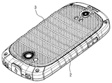
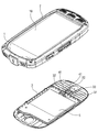
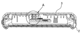
本発明の一実施形態である携帯電話機は、図1及び図2に示す如く、ディスプレイ(10)及び電話通信回路等の電子回路を内蔵した本体(1)と、該本体(1)を収容する合成樹脂製の筐体(2)と、本体(1)の背面に着脱可能に取り付けられた合成樹脂製の蓋体(3)とを具えている。
本体(1)の背面には、図5に示す如く電池収容室(13)が凹設され、該電池収容室(13)には電源となる電池(6)が収容されている。
本発明の一実施形態である携帯電話機は、図1及び図2に示す如く、ディスプレイ(10)及び電話通信回路等の電子回路を内蔵した本体(1)と、該本体(1)を収容する合成樹脂製の筐体(2)と、本体(1)の背面に着脱可能に取り付けられた合成樹脂製の蓋体(3)とを具えている。
本体(1)の背面には、図5に示す如く電池収容室(13)が凹設され、該電池収容室(13)には電源となる電池(6)が収容されている。
筐体(2)はOリング等を用いた周知の防水構造を有している。
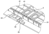
蓋体(3)の内面には、図4に示す如く、前記電池収容室(13)を包囲する様に延びるリブ(31)が突設されている。該リブ(31)には、図11に示す如く断面U字状の防水パッキン(7)が装着されている。従って、筐体(2)に蓋体(3)を取り付けることにより、防水パッキン(7)が本体(1)の表面に密着して、電池収容室(13)を含む空間が封止され、該空間に対して防水処理をすることができる。
蓋体(3)の内面には、図4に示す如く、前記電池収容室(13)を包囲する様に延びるリブ(31)が突設されている。該リブ(31)には、図11に示す如く断面U字状の防水パッキン(7)が装着されている。従って、筐体(2)に蓋体(3)を取り付けることにより、防水パッキン(7)が本体(1)の表面に密着して、電池収容室(13)を含む空間が封止され、該空間に対して防水処理をすることができる。
図4に示す如く、蓋体(3)の内面には、近距離無線通信用のアンテナ(4)がループ状に形成される。それと共に、該アンテナ(4)の近傍位置には、該アンテナ(4)に繋がる一対の電極(41)(41)が、左右に並べて配置される。これらの電極(41)(41)は金メッキによって形成される。
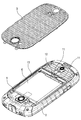
蓋体(3)の内面に形成されているアンテナ(4)は、図3に示す如く蓋体(3)の内面に貼着された電波遮断シート(5)によって覆われている。これによって、本体(1)側から発せられる電波がアンテナ(4)の性能に悪影響を及ぼすことが防止されている。
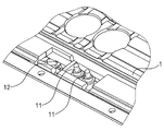
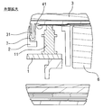
一方、本体(1)には、図5及び図7に示す如く一対の端子(11)(11)が突設されている。筐体(2)に蓋体(3)が取り付けられることによって、図8~図11に示す如く、各端子(11)の先端が各電極(41)の表面に圧接される。この結果、アンテナ(4)が本体(1)に内蔵された電子回路(図示省略)に接続されることになる。
蓋体(3)の内面には、図3及び図4に示す如く、電極(41)の近傍位置に、フック片(33)が突設される。本体(1)の背面には、図5に示す如く、端子(11)の近傍位置に、フック受け片(12)が突設される。筐体(2)に蓋体(3)が取り付けられることによって、フック片(33)がフック受け片(12)と係合して、端子(11)と電極(41)との圧接状態が安定的に維持される。
蓋体(3)の内面には、図4及び図6に示す如く、一対の電極(41)(41)に近接し且つ両電極(41)(41)を挟んで左右両側に、電極(41)の表面よりも高く突出する一対の突片(32)(32)が、一体成型により形成されている。一対の突片(32)(32)は、その間隔が指の太さよりも小さく、且つ各突片(32)の電極(41)に沿う方向の長さが電極(41)の長さよりも大きく形成されている。
筐体(2)に蓋体(3)を取り付けた状態で、蓋体(3)の突片(32)(32)が本体(1)と干渉しない様、本体(1)には逃げ部が形成されている。
筐体(2)に蓋体(3)を取り付けた状態で、蓋体(3)の突片(32)(32)が本体(1)と干渉しない様、本体(1)には逃げ部が形成されている。
上記携帯電話機によれば、図3に示す如く、一対の電極(41)(41)の左右両側に2つの突片(32)(32)が形成されている。そのため、筐体(2)から蓋体(3)を取り外した状態で、該蓋体(3)の内面に露出する一対の電極(41)(41)に指が触れようとしても、2つの突片(32)(32)は電極(41)の表面よりも高く形成されているので、その指は両突片(32)(32)の先端に当たって両電極(41)(41)との接触が抑止される。これによって、電極(41)の腐食が抑制される。
一対の電極(41)(41)の側部には、突片(32)よりも高く突出するフック片(33)が形成されている。一対の電極(41)(41)の近傍位置には、両電極(41)(41)に沿ってリブ(31)が延びている。従って、フック片(33)及びリブ(31)も、電極(41)に指が接触することを抑止する機能を発揮する。
又、上記携帯電話機によれば、2つの突片(32)(32)が、アンテナ(4)へ接近する方向に延びるリブ状に形成され、両突片(32)(32)の側端に電波遮断シート(5)の端縁が当接した状態で、電波遮断シート(5)が蓋体(3)の内面に貼着されている。
従って、組立工程において、電波遮断シート(5)を蓋体(3)の内面に貼着する際、電波遮断シート(5)の位置決めが容易なものとなる。
従って、組立工程において、電波遮断シート(5)を蓋体(3)の内面に貼着する際、電波遮断シート(5)の位置決めが容易なものとなる。
本発明の各部構成は上記実施の形態に限らず、クレームに記載された本発明の精神から逸脱しない範囲で当該技術分野の専門家であれば可能な種々の変形が可能である。例えば突片(32)は2つ設ける構成に限らず、電極(41)(41)を包囲して3つ以上を設けることも有効である。又、アンテナ(4)は、近距離無線通信用のアンテナに限らず、その他の周知のアンテナであってもよい。
(1) 本体
(11) 端子
(2) 筐体
(3) 蓋体
(31) リブ
(32) 突片
(33) フック片
(4) アンテナ
(41) 電極
(5) 電波遮断シート
(11) 端子
(2) 筐体
(3) 蓋体
(31) リブ
(32) 突片
(33) フック片
(4) アンテナ
(41) 電極
(5) 電波遮断シート
Claims (2)
- 電子部品が内蔵された本体と、
前記本体を収容する筐体と、
前記筐体に対して着脱可能に取り付けられた蓋体と、
前記蓋体に設置された無線通信用のアンテナと、
前記蓋体の内面に配備され、前記アンテナと繋がる一対の電極と、
前記本体に配備され、前記一対の電極と接触すべき一対の端子と、
前記蓋体の内面に形成され、前記一対の電極に近接し且つ両電極を挟んだ両側に、前記一対の電極の表面よりも高く突出する少なくとも2つの突片と、
を具える無線通信端末機。 - 前記アンテナは前記蓋体の内面に配備された近距離無線通信用のアンテナであって、
前記アンテナは、前記蓋体の内面に貼り付けられた電波遮断シートによって覆われており、前記電波遮断シートの端縁が前記少なくとも2つの突片に当接している請求項1に記載の無線通信端末機。
Priority Applications (1)
| Application Number | Priority Date | Filing Date | Title |
|---|---|---|---|
| US14/653,810 US9331733B2 (en) | 2012-12-18 | 2013-12-16 | Wireless communication terminal device |
Applications Claiming Priority (2)
| Application Number | Priority Date | Filing Date | Title |
|---|---|---|---|
| JP2012-275661 | 2012-12-18 | ||
| JP2012275661A JP6153719B2 (ja) | 2012-12-18 | 2012-12-18 | 無線通信端末機 |
Publications (1)
| Publication Number | Publication Date |
|---|---|
| WO2014098030A1 true WO2014098030A1 (ja) | 2014-06-26 |
Family
ID=50978360
Family Applications (1)
| Application Number | Title | Priority Date | Filing Date |
|---|---|---|---|
| PCT/JP2013/083630 Ceased WO2014098030A1 (ja) | 2012-12-18 | 2013-12-16 | 無線通信端末機 |
Country Status (3)
| Country | Link |
|---|---|
| US (1) | US9331733B2 (ja) |
| JP (1) | JP6153719B2 (ja) |
| WO (1) | WO2014098030A1 (ja) |
Cited By (1)
| Publication number | Priority date | Publication date | Assignee | Title |
|---|---|---|---|---|
| CN106657505A (zh) * | 2017-02-09 | 2017-05-10 | 广东欧珀移动通信有限公司 | 终端的壳体及终端 |
Families Citing this family (8)
| Publication number | Priority date | Publication date | Assignee | Title |
|---|---|---|---|---|
| USD782992S1 (en) * | 2014-02-12 | 2017-04-04 | Doro AB | Telephone |
| USD753641S1 (en) * | 2014-09-17 | 2016-04-12 | Tech 21 Licensing Limited | Mobile communications device cover |
| USD754652S1 (en) * | 2014-09-17 | 2016-04-26 | Tech 21 Licensing Limited | Mobile communications device cover |
| US9866256B2 (en) * | 2015-12-21 | 2018-01-09 | Panasonic Intellectual Property Management Co., Ltd. | Electronic apparatus |
| USD846542S1 (en) * | 2017-04-26 | 2019-04-23 | Stmec, Llc | Cover for a mobile communications device |
| USD862444S1 (en) | 2017-04-26 | 2019-10-08 | Stmec, Llc | Cover for a mobile communications device |
| USD862445S1 (en) | 2017-04-26 | 2019-10-08 | Stmec, Llc | Cover for a mobile communications device |
| USD876380S1 (en) * | 2017-07-21 | 2020-02-25 | Motorola Solutions, Inc. | Handheld communication device |
Citations (2)
| Publication number | Priority date | Publication date | Assignee | Title |
|---|---|---|---|---|
| JP2003234668A (ja) * | 2002-02-12 | 2003-08-22 | Matsushita Electric Ind Co Ltd | 通信機器 |
| JP2007189628A (ja) * | 2006-01-16 | 2007-07-26 | Orient Sokki Computer Kk | 携帯型電子機器、および通信波遮断具 |
Family Cites Families (11)
| Publication number | Priority date | Publication date | Assignee | Title |
|---|---|---|---|---|
| JPH06275249A (ja) * | 1993-03-18 | 1994-09-30 | Fujitsu Ltd | 携帯電子機器用電池パック装着構造 |
| JP2003216901A (ja) * | 1997-06-04 | 2003-07-31 | Sony Corp | 記録再生システム |
| JP3212967B2 (ja) * | 1999-04-30 | 2001-09-25 | 埼玉日本電気株式会社 | 携帯通信機およびその充電器 |
| JP4306143B2 (ja) * | 2001-04-27 | 2009-07-29 | 日本電気株式会社 | 携帯電話機 |
| US7136681B2 (en) * | 2001-10-31 | 2006-11-14 | Telefonaktiebolaget Lm Ericsson (Publ) | Electrically conductive carrier and patterning for controlling current distribution in a wireless communications device |
| JP4104474B2 (ja) * | 2003-03-17 | 2008-06-18 | 三洋電機株式会社 | 携帯電話機 |
| JP2007306287A (ja) * | 2006-05-11 | 2007-11-22 | Nec Saitama Ltd | 携帯電話機 |
| JP4698528B2 (ja) * | 2006-08-25 | 2011-06-08 | Necカシオモバイルコミュニケーションズ株式会社 | 携帯電子機器 |
| JP2010062734A (ja) * | 2008-09-02 | 2010-03-18 | Toshiba Corp | 無線装置、アンテナ装置及び無線システム |
| JP2011044778A (ja) | 2009-08-19 | 2011-03-03 | Panasonic Corp | 携帯無線機 |
| GB2501385B (en) * | 2010-10-21 | 2015-05-27 | Murata Manufacturing Co | Communication terminal device |
-
2012
- 2012-12-18 JP JP2012275661A patent/JP6153719B2/ja active Active
-
2013
- 2013-12-16 US US14/653,810 patent/US9331733B2/en active Active
- 2013-12-16 WO PCT/JP2013/083630 patent/WO2014098030A1/ja not_active Ceased
Patent Citations (2)
| Publication number | Priority date | Publication date | Assignee | Title |
|---|---|---|---|---|
| JP2003234668A (ja) * | 2002-02-12 | 2003-08-22 | Matsushita Electric Ind Co Ltd | 通信機器 |
| JP2007189628A (ja) * | 2006-01-16 | 2007-07-26 | Orient Sokki Computer Kk | 携帯型電子機器、および通信波遮断具 |
Cited By (2)
| Publication number | Priority date | Publication date | Assignee | Title |
|---|---|---|---|---|
| CN106657505A (zh) * | 2017-02-09 | 2017-05-10 | 广东欧珀移动通信有限公司 | 终端的壳体及终端 |
| CN106657505B (zh) * | 2017-02-09 | 2023-08-18 | 深圳市欢太科技有限公司 | 终端的壳体及终端 |
Also Published As
| Publication number | Publication date |
|---|---|
| US20150326267A1 (en) | 2015-11-12 |
| JP6153719B2 (ja) | 2017-06-28 |
| US9331733B2 (en) | 2016-05-03 |
| JP2014120981A (ja) | 2014-06-30 |
Similar Documents
| Publication | Publication Date | Title |
|---|---|---|
| WO2014098030A1 (ja) | 無線通信端末機 | |
| CN103633426B (zh) | 天线结构和移动终端设备 | |
| US20120056789A1 (en) | Antenna booster case for enhancing transmission/reception sensibility of mobile device | |
| US10158163B2 (en) | Mobile terminal | |
| TWI482363B (zh) | 行動裝置 | |
| TWI694637B (zh) | 天線模組及具有該天線模組之穿戴式電子裝置 | |
| JP5027579B2 (ja) | 送受信装置 | |
| CN106128827B (zh) | 侧键结构及移动终端 | |
| KR101326653B1 (ko) | 휴대 단말기 | |
| JP2013055312A (ja) | 電磁波遮断ケース | |
| JP2015046879A (ja) | 無線通信装置 | |
| CN101908429B (zh) | 按键固定结构以及便携式移动终端 | |
| WO2014148089A1 (ja) | 携帯機器 | |
| JP5873756B2 (ja) | 携帯電子機器 | |
| JP2014057165A (ja) | 防水携帯端末 | |
| JP2016066906A (ja) | 携帯無線機用ケース | |
| WO2015033530A1 (ja) | 電子機器 | |
| JP2013247655A (ja) | 電子機器 | |
| JP2013110642A (ja) | 携帯端末 | |
| CN209948031U (zh) | 腕戴设备及其主体 | |
| JP2010028871A5 (ja) | ||
| JP5417487B2 (ja) | 電子装置 | |
| JP3490899B2 (ja) | 携帯型無線通信機器 | |
| KR200367322Y1 (ko) | 휴대폰 단말기의 전자파 차폐를 위한 마킹된 키보드 커버 | |
| KR101789537B1 (ko) | 이동 단말기 |
Legal Events
| Date | Code | Title | Description |
|---|---|---|---|
| 121 | Ep: the epo has been informed by wipo that ep was designated in this application |
Ref document number: 13865522 Country of ref document: EP Kind code of ref document: A1 |
|
| NENP | Non-entry into the national phase |
Ref country code: DE |
|
| WWE | Wipo information: entry into national phase |
Ref document number: 14653810 Country of ref document: US |
|
| 122 | Ep: pct application non-entry in european phase |
Ref document number: 13865522 Country of ref document: EP Kind code of ref document: A1 |