WO2014097746A1 - 樹脂チューブおよび配管接続構造 - Google Patents
樹脂チューブおよび配管接続構造 Download PDFInfo
- Publication number
- WO2014097746A1 WO2014097746A1 PCT/JP2013/079191 JP2013079191W WO2014097746A1 WO 2014097746 A1 WO2014097746 A1 WO 2014097746A1 JP 2013079191 W JP2013079191 W JP 2013079191W WO 2014097746 A1 WO2014097746 A1 WO 2014097746A1
- Authority
- WO
- WIPO (PCT)
- Prior art keywords
- resin tube
- inner layer
- pipe body
- retainer
- outer layer
- Prior art date
- Legal status (The legal status is an assumption and is not a legal conclusion. Google has not performed a legal analysis and makes no representation as to the accuracy of the status listed.)
- Ceased
Links
Images









Classifications
-
- B—PERFORMING OPERATIONS; TRANSPORTING
- B29—WORKING OF PLASTICS; WORKING OF SUBSTANCES IN A PLASTIC STATE IN GENERAL
- B29C—SHAPING OR JOINING OF PLASTICS; SHAPING OF MATERIAL IN A PLASTIC STATE, NOT OTHERWISE PROVIDED FOR; AFTER-TREATMENT OF THE SHAPED PRODUCTS, e.g. REPAIRING
- B29C48/00—Extrusion moulding, i.e. expressing the moulding material through a die or nozzle which imparts the desired form; Apparatus therefor
- B29C48/03—Extrusion moulding, i.e. expressing the moulding material through a die or nozzle which imparts the desired form; Apparatus therefor characterised by the shape of the extruded material at extrusion
- B29C48/09—Articles with cross-sections having partially or fully enclosed cavities, e.g. pipes or channels
-
- B—PERFORMING OPERATIONS; TRANSPORTING
- B32—LAYERED PRODUCTS
- B32B—LAYERED PRODUCTS, i.e. PRODUCTS BUILT-UP OF STRATA OF FLAT OR NON-FLAT, e.g. CELLULAR OR HONEYCOMB, FORM
- B32B1/00—Layered products having a non-planar shape
-
- B—PERFORMING OPERATIONS; TRANSPORTING
- B32—LAYERED PRODUCTS
- B32B—LAYERED PRODUCTS, i.e. PRODUCTS BUILT-UP OF STRATA OF FLAT OR NON-FLAT, e.g. CELLULAR OR HONEYCOMB, FORM
- B32B3/00—Layered products comprising a layer with external or internal discontinuities or unevennesses, or a layer of non-planar shape; Layered products comprising a layer having particular features of form
- B32B3/02—Layered products comprising a layer with external or internal discontinuities or unevennesses, or a layer of non-planar shape; Layered products comprising a layer having particular features of form characterised by features of form at particular places, e.g. in edge regions
- B32B3/04—Layered products comprising a layer with external or internal discontinuities or unevennesses, or a layer of non-planar shape; Layered products comprising a layer having particular features of form characterised by features of form at particular places, e.g. in edge regions characterised by at least one layer folded at the edge, e.g. over another layer ; characterised by at least one layer enveloping or enclosing a material
-
- F—MECHANICAL ENGINEERING; LIGHTING; HEATING; WEAPONS; BLASTING
- F02—COMBUSTION ENGINES; HOT-GAS OR COMBUSTION-PRODUCT ENGINE PLANTS
- F02M—SUPPLYING COMBUSTION ENGINES IN GENERAL WITH COMBUSTIBLE MIXTURES OR CONSTITUENTS THEREOF
- F02M37/00—Apparatus or systems for feeding liquid fuel from storage containers to carburettors or fuel-injection apparatus; Arrangements for purifying liquid fuel specially adapted for, or arranged on, internal-combustion engines
- F02M37/0011—Constructional details; Manufacturing or assembly of elements of fuel systems; Materials therefor
- F02M37/0017—Constructional details; Manufacturing or assembly of elements of fuel systems; Materials therefor related to fuel pipes or their connections, e.g. joints or sealings
-
- F—MECHANICAL ENGINEERING; LIGHTING; HEATING; WEAPONS; BLASTING
- F16—ENGINEERING ELEMENTS AND UNITS; GENERAL MEASURES FOR PRODUCING AND MAINTAINING EFFECTIVE FUNCTIONING OF MACHINES OR INSTALLATIONS; THERMAL INSULATION IN GENERAL
- F16L—PIPES; JOINTS OR FITTINGS FOR PIPES; SUPPORTS FOR PIPES, CABLES OR PROTECTIVE TUBING; MEANS FOR THERMAL INSULATION IN GENERAL
- F16L11/00—Hoses, i.e. flexible pipes
- F16L11/04—Hoses, i.e. flexible pipes made of rubber or flexible plastics
- F16L11/12—Hoses, i.e. flexible pipes made of rubber or flexible plastics with arrangements for particular purposes, e.g. specially profiled, with protecting layer, heated, electrically conducting
-
- F—MECHANICAL ENGINEERING; LIGHTING; HEATING; WEAPONS; BLASTING
- F16—ENGINEERING ELEMENTS AND UNITS; GENERAL MEASURES FOR PRODUCING AND MAINTAINING EFFECTIVE FUNCTIONING OF MACHINES OR INSTALLATIONS; THERMAL INSULATION IN GENERAL
- F16L—PIPES; JOINTS OR FITTINGS FOR PIPES; SUPPORTS FOR PIPES, CABLES OR PROTECTIVE TUBING; MEANS FOR THERMAL INSULATION IN GENERAL
- F16L37/00—Couplings of the quick-acting type
- F16L37/08—Couplings of the quick-acting type in which the connection between abutting or axially overlapping ends is maintained by locking members
- F16L37/084—Couplings of the quick-acting type in which the connection between abutting or axially overlapping ends is maintained by locking members combined with automatic locking
- F16L37/088—Couplings of the quick-acting type in which the connection between abutting or axially overlapping ends is maintained by locking members combined with automatic locking by means of a split elastic ring
- F16L37/0885—Couplings of the quick-acting type in which the connection between abutting or axially overlapping ends is maintained by locking members combined with automatic locking by means of a split elastic ring with access to the split elastic ring from a radial or tangential opening in the coupling
-
- F—MECHANICAL ENGINEERING; LIGHTING; HEATING; WEAPONS; BLASTING
- F16—ENGINEERING ELEMENTS AND UNITS; GENERAL MEASURES FOR PRODUCING AND MAINTAINING EFFECTIVE FUNCTIONING OF MACHINES OR INSTALLATIONS; THERMAL INSULATION IN GENERAL
- F16L—PIPES; JOINTS OR FITTINGS FOR PIPES; SUPPORTS FOR PIPES, CABLES OR PROTECTIVE TUBING; MEANS FOR THERMAL INSULATION IN GENERAL
- F16L37/00—Couplings of the quick-acting type
- F16L37/08—Couplings of the quick-acting type in which the connection between abutting or axially overlapping ends is maintained by locking members
- F16L37/12—Couplings of the quick-acting type in which the connection between abutting or axially overlapping ends is maintained by locking members using hooks, pawls, or other movable or insertable locking members
- F16L37/14—Joints secured by inserting between mating surfaces an element, e.g. a piece of wire, a pin, a chain
- F16L37/142—Joints secured by inserting between mating surfaces an element, e.g. a piece of wire, a pin, a chain where the securing element is inserted tangentially
- F16L37/144—Joints secured by inserting between mating surfaces an element, e.g. a piece of wire, a pin, a chain where the securing element is inserted tangentially the securing element being U-shaped
-
- B—PERFORMING OPERATIONS; TRANSPORTING
- B29—WORKING OF PLASTICS; WORKING OF SUBSTANCES IN A PLASTIC STATE IN GENERAL
- B29L—INDEXING SCHEME ASSOCIATED WITH SUBCLASS B29C, RELATING TO PARTICULAR ARTICLES
- B29L2009/00—Layered products
-
- B—PERFORMING OPERATIONS; TRANSPORTING
- B32—LAYERED PRODUCTS
- B32B—LAYERED PRODUCTS, i.e. PRODUCTS BUILT-UP OF STRATA OF FLAT OR NON-FLAT, e.g. CELLULAR OR HONEYCOMB, FORM
- B32B2274/00—Thermoplastic elastomer material
-
- B—PERFORMING OPERATIONS; TRANSPORTING
- B32—LAYERED PRODUCTS
- B32B—LAYERED PRODUCTS, i.e. PRODUCTS BUILT-UP OF STRATA OF FLAT OR NON-FLAT, e.g. CELLULAR OR HONEYCOMB, FORM
- B32B2307/00—Properties of the layers or laminate
- B32B2307/50—Properties of the layers or laminate having particular mechanical properties
- B32B2307/51—Elastic
-
- B—PERFORMING OPERATIONS; TRANSPORTING
- B32—LAYERED PRODUCTS
- B32B—LAYERED PRODUCTS, i.e. PRODUCTS BUILT-UP OF STRATA OF FLAT OR NON-FLAT, e.g. CELLULAR OR HONEYCOMB, FORM
- B32B2597/00—Tubular articles, e.g. hoses, pipes
-
- F—MECHANICAL ENGINEERING; LIGHTING; HEATING; WEAPONS; BLASTING
- F16—ENGINEERING ELEMENTS AND UNITS; GENERAL MEASURES FOR PRODUCING AND MAINTAINING EFFECTIVE FUNCTIONING OF MACHINES OR INSTALLATIONS; THERMAL INSULATION IN GENERAL
- F16L—PIPES; JOINTS OR FITTINGS FOR PIPES; SUPPORTS FOR PIPES, CABLES OR PROTECTIVE TUBING; MEANS FOR THERMAL INSULATION IN GENERAL
- F16L11/00—Hoses, i.e. flexible pipes
- F16L11/04—Hoses, i.e. flexible pipes made of rubber or flexible plastics
-
- F—MECHANICAL ENGINEERING; LIGHTING; HEATING; WEAPONS; BLASTING
- F16—ENGINEERING ELEMENTS AND UNITS; GENERAL MEASURES FOR PRODUCING AND MAINTAINING EFFECTIVE FUNCTIONING OF MACHINES OR INSTALLATIONS; THERMAL INSULATION IN GENERAL
- F16L—PIPES; JOINTS OR FITTINGS FOR PIPES; SUPPORTS FOR PIPES, CABLES OR PROTECTIVE TUBING; MEANS FOR THERMAL INSULATION IN GENERAL
- F16L2201/00—Special arrangements for pipe couplings
- F16L2201/10—Indicators for correct coupling
Definitions
- the present invention relates to a resin tube into which a mating member is inserted and a pipe connection structure including the resin tube.
- Patent Documents 1 to 5 describe a structure in which a seal member is disposed between a pipe body and a diameter-enlarged portion of the resin tube by previously expanding the diameter of the end portion of the resin tube.
- An object of this invention is to provide the resin tube which can aim at reduction of a sealing member, ensuring a sealing performance, and a piping connection structure using the same.
- the resin tube according to this means is a resin tube into which a mating member is inserted from an opening end, and includes an outer layer and an inner layer having a smaller elastic modulus than the outer layer, and the outer layer is radially inward of the opening end side of the resin tube.
- the inner layer is compressed by the main protrusion and the counterpart material when the counterpart material is inserted into the resin tube.
- the sealing performance can be exhibited by the inner layer being compressed by the main protrusion and the counterpart material.
- corresponds to the site
- the inner layer may be formed of a thermoplastic elastomer. As a result, the inner layer is elastically deformed to reliably exhibit the sealing performance.
- the outer layer and the inner layer are preferably bonded. Thereby, it can control that an outer layer and an inner layer shift relatively in the direction of an axis. As a result, even if a force that causes the counterpart material to shift in the axial direction with respect to the resin tube acts, the main projection of the outer layer can reliably compress the specific portion of the inner layer. As a result, stable sealing performance can be exhibited.
- the outer layer and the inner layer may be molded in a state of being integrally bonded by extrusion molding. Thereby, shaping
- the tangent on the inner peripheral surface of the inner layer in the axial cross section is defined as the inner layer tangent, and the inner layer tangent corresponding to the insertion side of the mating member of the main projection is preferably inclined with respect to the central axis. Thereby, it becomes easy to insert the counterpart material into the resin tube.
- the outer layer includes annular sub-projections projecting radially inward on both axial sides of the main projection, and the sub-projection extends in the axial direction when a portion of the inner layer corresponding to the main projection is compressed. You may make it suppress escape. Both sub-projections can exhibit high sealing performance by suppressing the escape in the axial direction of the portion to be compressed of the inner layer.
- the height of the sub-projection may be formed lower than the height of the main projection, and the inner diameter of the portion corresponding to the sub-projection in the inner layer may be formed larger than the outer diameter of the counterpart material.
- protrusion does not exhibit sealing performance. That is, by dividing each part of the inner layer into a part to be compressed and a part that exhibits the escape suppressing function, high sealing performance can be exhibited as a whole.
- the present invention can also be understood as a pipe connection structure using the above-described resin tube.
- the pipe connection structure according to the present means includes a pipe body having an annular protrusion protruding radially outward at a position away from the tip, a resin tube into which the tip side of the pipe body is inserted from the open end, and a tubular shape And a retainer that is connected to the axial end of the resin tube and that locks on the annular protrusion of the pipe body in a state in which the pipe body is inserted, thereby restricting removal of the pipe body.
- the resin tube includes an outer layer and an inner layer having a smaller elastic modulus than the outer layer.
- the outer layer includes an annular main protrusion that protrudes radially inward on the opening end side of the resin tube. When being inserted into the main body, it is compressed by the main projection and the pipe body.
- the sealing performance can be exhibited by compressing the inner layer by the main projection and the pipe body. Furthermore, the site
- a retainer separate from the resin tube is used.
- the retainer regulates the removal of the pipe body.
- the resin tube is hooked on the pipe body, if the number of insertions / removals of the pipe body increases, the hooking force of the resin tube decreases. For this reason, it is required that the pipe body disconnection restricting function be provided in a member different from the resin tube. Therefore, by using a retainer separate from the resin tube as described above, even if the resin tube is inserted and removed without being caught by the annular protrusion of the pipe body, the resin tube is not affected at all. Absent. Therefore, according to this means, the durability as a resin tube can be improved.
- the above-described preferred aspects of the resin tube can be similarly applied.
- the inner layer and the outer peripheral surface of the resin tube and the inner peripheral surface of the retainer may be provided with a locking pair that hooks each other in the axial direction, and the resin tube and the retainer may be connected by the locking pair. Thereby, a resin tube and a retainer can be connected reliably.
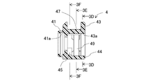
- FIG. 1A It is a front view of the retainer of FIG. 1A. It is a top view (top view) of the retainer of FIG. 3A.
- 3C is a 3C-3C cross-sectional view of the retainer of FIG. 3B.
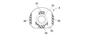
- FIG. It is 3D-3D sectional drawing of the retainer of FIG. 3C. It is 3E-3E sectional drawing of the retainer of FIG. 3C. It is 3F-3F sectional drawing of the retainer of FIG. 3C.
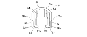
- FIG. 4B is a right side view of the checker in FIG.
- FIG. 4A (viewed from the direction 4B in FIG. 4A).
- 4B is a left side view of the checker in FIG. 4A (viewed from the direction 4C in FIG. 4A).
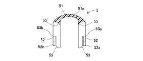
- FIG. 4D is a 4D-4D cross-sectional view of the checker of FIG. 4A. It is an expanded sectional view of the axial direction of the resin tube of a second embodiment. It is an expanded sectional view of the direction of an axis in the state where a pipe body was inserted into a resin tube of Drawing 5A.
- the pipe connection structure constitutes, for example, a gasoline fuel pipe 1 of an automobile and corresponds to a connecting portion between a pipe body 2 and a resin tube 3.
- the pipe 1 includes a pipe body 2, a resin tube 3, a retainer 4, and a checker 5.
- the resin tube 3 and the retainer 4 are connected, and the checker 5 is attached to the retainer 4.
- the pipe body 2 is inserted into the retainer 4 as shown in the pipe body insertion state of FIG. 1B.
- the confirmation state diagram of FIG. 1C it is confirmed that the pipe body 2 is inserted into the normal position of the retainer 4 by pushing the checker 5.
- the retainer 4 will be in a release state by pushing in the checker 5 further, and the pipe body 2 can be pulled out from the retainer 4.
- the retainer 4 and the checker 5 have substantially the same configuration as the second housing (30) and the checker (50) described in Japanese Patent No. 4937426.
- the pipe body 2 is made of metal and formed in a cylindrical shape, and includes an annular protrusion 2a that protrudes radially outward at a position away from the tip.
- the tip of the pipe body 2 is chamfered.
- the resin tube 3 is formed in a multilayer structure over the entire length by extrusion molding.
- the resin tube 3 has a two-layer structure of an outer layer 31 and an inner layer 32.
- the outer layer 31 has a relatively large elastic modulus
- the inner layer 32 has a relatively small elastic modulus. That is, the outer layer 31 is harder than the inner layer 32.
- the outer layer 31 and the inner layer 32 are shape
- the outer layer 31 is formed of a thermoplastic resin
- the inner layer 32 is formed of a thermoplastic elastomer.
- the outer layer 31 is formed of “UBESTA (registered trademark) 3030JI5L” manufactured by Ube Industries, Ltd.
- the inner layer 32 is formed of, for example, “UBESTA XPA (registered trademark) 9055X1” manufactured by Ube Industries, Ltd.
- the elastic modulus of the outer layer 31 is 400 MPa
- the elastic modulus of the inner layer 32 is 260 MPa.
- annular main protrusion 31a protruding inward in the radial direction is provided at a position slightly away from the opening end of the resin tube 3 in the outer layer 31.
- the minimum inner diameter D31a of the main protrusion 31a is larger than the outer diameter Dp (hereinafter referred to as the pipe tip outer diameter) of the cylindrical outer peripheral surface at the tip side portion of the annular protrusion 2a of the pipe body 2.
- the longitudinal section (axial section) of the main protrusion 31a is formed in a substantially arc shape. That is, the opening side (the insertion side of the pipe body 2) and the opposite opening side of the main projection 31a are both inclined with respect to the central axis X. In other words, the insertion side tangent (outer layer tangent) of the main protrusion 31 a is inclined with respect to the central axis X. Further, the outer layer tangent on the opposite side of the main projection 31 a is also inclined with respect to the central axis X.
- the longitudinal section of the main protrusion 31a is arcuate, but it may be trapezoidal.
- an outer protrusion 31b protruding outward in the radial direction is formed at the opening end of the resin tube 3 in the outer layer 31.
- the outer protrusion 31b is located closer to the opening side of the resin tube 3 than the main protrusion 31a.
- the inner layer 32 is formed so as to follow the inner peripheral surface shape of the outer layer 31 over the entire length of the resin tube 3.
- the inner layer 32 is formed with substantially the same thickness. That is, a portion 32 a corresponding to the main protrusion 31 a of the outer layer 31 in the inner layer 32 protrudes inward in the radial direction.
- the portion 32a of the inner layer 32 is referred to as an inner layer protrusion.
- the inner layer tangent L1 on the opening side and the inner layer tangent L2 on the opposite side of the inner layer protrusion 32a are both inclined with respect to the central axis X.
- the minimum inner diameter D32a of the inner layer protrusion 32a is smaller than the pipe tip outer diameter Dp.
- the inner diameters D32b and D32c of the cylindrical inner peripheral surface portions 32b and 32c in the axially adjacent portions of the inner layer protrusion 32a are larger than the pipe tip outer diameter Dp.
- the inner layer 32 does not need to have the same thickness, and may have a different thickness as long as the following is satisfied. That is, the inner layer projection 32a is formed, the minimum inner diameter D32a of the inner layer projection 32a is smaller than the pipe tip outer diameter Dp, and the inner diameters D32b and D32c of the cylindrical inner peripheral surface portions 32b and 32c on both axial sides of the inner layer projection 32a are the pipe tip outer diameter. What is necessary is just to satisfy that it is larger than Dp.
- the inner diameter D32b of the cylindrical inner peripheral surface portion 32b on the opening side from the inner layer protrusion 32a is larger than the pipe tip outer diameter Dp. Therefore, the pipe body 2 can be easily inserted into the resin tube 3. Furthermore, since the minimum inner diameter D32a of the inner layer protrusion 32a is smaller than the pipe tip outer diameter Dp, when the pipe body 2 is inserted, the tip of the pipe body 2 comes into contact with the inclined surface of the inner layer protrusion 32a. Since the pipe body 2 contacts the inclined surface of the inner layer projection 32a, further insertion of the pipe body 2 is relatively easy.
- the minimum inner diameter D31a of the main projection 31a of the outer layer 31 is larger than the outer diameter Dp of the pipe tip, and the elastic modulus of the inner layer 32 is smaller than the elastic modulus of the outer layer 31. Therefore, when the pipe body 2 is further inserted, the inner layer protrusion 32 a is compressed in the radial direction by the pipe body 2 and the main protrusion 31 a of the outer layer 31.
- An inner diameter D32c of the cylindrical inner peripheral surface portion 32c on the opposite side of the inner layer protrusion 32a is larger than the pipe tip outer diameter Dp. Therefore, a gap is formed between the tip of the pipe body 2 and the inner layer 32.
- the inner layer projection 32a is compressed by the main projection 31a of the outer layer 31 and the pipe body 2, so that the inner layer projection 32a exhibits sealing performance.
- the inner layer protrusion 32 a corresponds to a portion where the main protrusion 31 a of the outer layer 31 is provided. That is, in the inner layer 32, the local site
- high sealing performance can be exhibited by the inner layer protrusion 32a.
- the inner layer 32 is formed of a thermoplastic elastomer, high sealing performance can be more reliably exhibited by elastic deformation of the inner layer protrusion 32a.
- outer layer 31 and the inner layer 32 are bonded. Thereby, it can control that outer layer 31 and inner layer 32 shift relatively in the direction of an axis. As a result, even if a force that causes the pipe body 2 to shift in the axial direction with respect to the resin tube 3 acts, the main projection 31a of the outer layer 31 can reliably compress the inner layer projection 32a. As a result, stable sealing performance can be exhibited.
- the retainer 4 includes a tube locking portion 41, a retainer main body 42, and a retainer diameter-expanding elastic deformation claw 49.
- the tube locking portion 41 is formed in a cylindrical shape, and an annular groove 41a is formed on the inner peripheral surface of the tube locking portion 41 as shown in FIG. 3C.
- the annular groove 41a In the annular groove 41a, the outer protrusion 31b of the outer layer 31 of the resin tube 3 is fitted. In this way, the retainer 4 and the resin tube 3 are connected.
- the tube locking portion 41 of the retainer 4 and the outer layer 31 of the resin tube 3 are bonded together by welding, an adhesive, or the like, in addition to uneven catch.
- the retainer main body 42 is a portion that is integrally formed with the tube locking portion 41 and is not deformed in the sense that it is distinguished from the retainer diameter-enlarged elastic deformation claw 49.
- the retainer body 42 includes an open end seat member 43, a lower connecting member 44, a first locking portion 45, a second locking portion 46, a guide portion 47, and a stopper 48.
- the open end seat member 43 is disposed at a distance from the tube locking portion 41 in the axial direction.
- the opening end seat member 43 is formed with a center hole 43a having a size capable of passing through the annular protrusion 2a of the pipe body 2.
- second locking holes 46 a pair of locking holes (hereinafter referred to as “second locking holes 46”) as the second locking portions 46 are formed on the left and right sides of FIG. 3D of the center hole 43 a when viewing the open end seat member 43 from the axial direction.
- locking parts 46 and 46 are penetrated and formed in the axial direction.
- the pair of second locking portions 46, 46 are hooked by the tip protrusions 52 a, 52 b of the axial elastic deformation claws 52, 52 of the checker 5.
- a pair of upper notches 43b and 43b forming a plane seat are formed above the pair of second locking portions 46 and 46 on the outer peripheral surface of the open end seat member 43.
- the pair of upper notches 43b and 43b are for initial positioning of the axial elastic deformation claws 52 and 52 of the checker 5 in order to obtain the initial state shown in FIG. 1A. That is, the pair of upper cutouts 43 b and 43 b are cutouts for facilitating mounting of the checker 5 on the retainer main body 42.
- a pair of lower notches 43c and 43c forming a plane seat are formed below the pair of second locking portions 46 and 46 on the outer peripheral surface of the open end seat member 43, respectively.
- the pair of lower cutouts 43c and 43c are for positioning the axial elastic deformation claws 52 and 52 of the checker 5 in the locking confirmation completion state shown in FIG. 1C.
- the lower connecting member 44 is a portion that connects the lower portion of the tube locking portion 41 and the lower portion of the open end seat member 43 in the axial direction.
- locking part 45 is formed in the semicircular arc shape opened toward upper direction, as shown to FIG. 3F.
- the first locking portion 45 is provided on the tube locking portion 41 side in the upper side surface of the lower connecting member 44.
- locking part 45 is provided in the position which does not interfere with the cyclic
- Both ends of the first locking portion 45 are formed in acute angles, and the left and right side surfaces of the first locking portion 45 in FIG. 3F are formed in a vertical flat shape.
- the guide part 47 connects the upper side of the tube locking part 41 and the upper side of the open end seat member 43 as shown in FIGS. 3B, 3C, 3E and 3F.
- the guide portion 47 is provided at a position where it does not interfere with the annular protrusion 2a of the pipe body 2 indicated by a two-dot chain line in FIG. 3F.
- the pair of stoppers 48, 48 are located at both lateral positions of the center hole of the tube locking portion 41 (left and right sides in FIGS. 3E and 3F) and the open end seat member 43.
- the lateral positions of the center hole 43a are connected to each other.
- the pair of stoppers 48, 48 are provided at positions that do not interfere with the annular protrusion 2a of the pipe body 2 indicated by a two-dot chain line in FIG. 3F.
- a notch 48a is formed on the upper side of the central portion in the axial direction of the pair of stoppers 48,48.
- This notch 48a allows the diameter of the retainer diameter-enlarging elastic deforming claw 49 of the retainer 4 to be expanded in the pipe body insertion state shown in FIG. 1B, and when the diameter expansion amount reaches a set amount, the retainer 4 expands the retainer diameter.
- the elastic deformation claw 49 has a function of restricting the diameter expansion.
- the retainer diameter-expanding elastic deformation claw 49 of the retainer 4 is formed in a C-shape that opens upward as shown in FIG. 3E.
- the retainer diameter-expanding elastic deformation claw 49 can be expanded in diameter by elastic deformation.
- the retainer diameter-expanding elastic deformation claw 49 is provided at the substantially central portion in the axial direction on the upper side surface of the lower connecting member 44. That is, the retainer diameter-expanding elastic deformation claw 49 is provided between the opening end seat member 43 and the first locking portion 45 in the axial direction.
- the retainer diameter-expanding elastic deformation claw 49 is provided in the position which interferes with the cyclic
- tip end surfaces 49a and 49b of the retainer diameter-expanding elastic deformation claw 49 are formed in a shape that is inclined inward as shown in FIG. 3E. This is because when the distal end surfaces 49a and 49b of the retainer diameter-expanding elastic deformation claw 49 are pushed by the release portions 55 and 55 of the checker 5, the retainer diameter-expansion elastic deformation claw 49 expands in diameter.
- end surfaces 49c and 49d on the insertion side of the pipe body 2 out of the distal end side of the retainer diameter-expanding elastic deformation claw 49 are, as shown in FIG. 3B, from the insertion side (right side in FIG. 3B) of the pipe body 2.
- the checker 5 is a member for confirming that the annular protrusion 2 a of the pipe body 2 is inserted at a normal position in the retainer 4 as described in the “Summary of piping connection structure” section.
- the checker 5 includes a checker diameter-expanding elastic deformation claw 51, an axial elastic deformation claw 52, a gap interposed member 53, a guide part 54, and a release part 55.
- the checker diameter-expanding elastic deformation claw 51 is formed in a C-shape that can be expanded by elastic deformation. Protrusions 51 a and 51 b projecting inward are formed at both ends of the checker diameter-expanding elastic deformation claw 51.
- the checker diameter-expanding elastic deformation claw 51 is locked to the first locking portion 45 of the retainer 4 in a state where the diameter is not expanded, so that the checker 5 is restricted from sliding with respect to the retainer main body 42.
- the checker diameter-expanding elastic deformation claw 51 is expanded in diameter by the annular protrusion 2 a of the pipe body 2 after passing through the retainer diameter-expansion elastic deformation claw 49. Then, when the checker diameter-expanding elastic deformation claw 51 is expanded, the lock on the first locking portion 45 is released, and the checker 5 is in a state in which the checker 5 can slide with respect to the retainer main body 42.
- the pair of axial elastic deformation claws 52, 52 are provided on the base portion 51 c of the checker diameter-expanding elastic deformation claw 51.
- the pair of axial elastic deformation claws 52, 52 are provided at a distance from the checker diameter-expanding elastic deformation claws 51 in the left-right direction in FIG. 4A (corresponding to the axial direction in FIG. 1A).
- claws 52 and 52 is formed so that bending deformation is possible in the left-right direction of FIG. 4A.
- Protrusions 52a and 52b projecting toward the right side in FIG. 4A are formed at the tips of the axial elastic deformation claws 52 and 52, respectively.
- the axial elastic deformation claws 52, 52 are restrained from being deformed by the retainer diameter-expanding elastic deformation claw 49 in a state in which the retainer diameter-expansion elastic deformation claw 49 is expanded in diameter.
- the state locked to the two locking portions 46 is maintained.
- the axial elastic deformation claws 52 and 52 are locked to the second locking portion 46 of the retainer main body 42, whereby the checker 5 is restricted from sliding with respect to the retainer main body 42.
- the axial elastic deformation claws 52, 52 can be released from the retainer main body 42 with respect to the second locking portion 46 in a state in which the retainer diameter-expanding elastic deformation claws 49 have returned to their shapes. In this state, the retainer body 42 can slide.
- the pair of gap interposed members 53 and 53 are formed on the radially inner side of the respective axial elastic deformation claws 52 and 52 through slits 53a and 53b.
- the pair of gap interposed members 53 and 53 are interposed in the axial gap between the open end seat member 43 of the retainer main body 42 and the retainer diameter-expanding elastic deformation claw 49 during the confirmation state shown in FIG. 1C from the initial state shown in FIG. 1A. To do.
- the guide portions 54, 54 are provided on the base 51 c of the checker diameter-expanding elastic deformation claw 51 and are formed inside the C-shape of the checker diameter-expansion elastic deformation claw 51. These guide portions 54, 54 are formed at a distance corresponding to the width of the guide portion 47 of the retainer 4.
- the guide portions 54 and 54 of the checker 5 are engaged with the guide portion 47 of the retainer 4, thereby restricting relative rotation between the retainer 4 and the checker 5, and a relative sliding operation in the vertical direction in the figure. Has a function of guiding.
- the release portions 55 and 55 are provided on the base portion 51c of the checker diameter-expanding elastic deformation claw 51, and are formed between the axial elastic deformation claw 52 and the guide portion 54 in the axial direction. Yes. As shown in FIG. 4D, the release portions 55 and 55 are inclined from the inside to the outside. The release portions 55 and 55 are formed in a shape corresponding to the inclination of the front end surfaces 49 a and 49 b of the retainer diameter-expanding elastic deformation claw 49. The release portions 55 and 55 expand the diameter of the retainer diameter-expanding elastic deformation claw 49 when the checker 5 slides with respect to the retainer 4.
- the resin tube 3 itself has a function as a seal member. Therefore, according to the present embodiment, high sealing performance between the pipe body 2 and the resin tube 3 can be ensured without using a sealing member as a separate member such as an O-ring. As a result, the number of parts can be reduced, and the number of assembling steps can be reduced.
- the piping 1 uses a retainer 4 that is separate from the resin tube 3.
- the retainer 4 regulates the removal of the pipe body 2. If the configuration in which the resin tube 3 is hooked on the pipe body 2 is increased, the hooking force of the resin tube 3 is reduced if the number of insertions / removals of the pipe body 2 is increased. For this reason, it is better to provide a member that is different from the resin tube 3 with a function of restricting the removal of the pipe body 2. Therefore, by using the retainer 4 that is separate from the resin tube 3, even if the resin tube 3 is inserted and removed without being caught by the annular protrusion 2 a of the pipe body 2, the resin tube 3 has no effect. Not receive. Therefore, durability as the resin tube 3 can be improved.
- the outer layer 31 includes annular sub-projections 31c and 31d projecting radially inward on both axial sides of the main projection 31a.
- the protrusion heights of the sub-projections 31c and 31d are lower than the protrusion height of the main protrusion 31a. That is, the minimum inner diameters D31c and D31d of the sub-projections 31c and 31d are larger than the minimum inner diameter D31a of the main projection 31a.
- the axial widths of the sub-projections 31c and 31d are considerably smaller than the main projection 31a. That is, the sub-projections 31c and 31d are minute projections.
- the inner layer 32 is formed so as to follow the shape of the inner peripheral surface of the outer layer 31 as in the above embodiment. That is, on the inner peripheral surface of the inner layer 32, portions 32d and 32e (hereinafter referred to as inner layer small protrusions) corresponding to the sub-projections 31c and 31d of the outer layer 31 protrude in the radial direction. At this time, the minimum inner diameters D32d and D32e of the inner layer small protrusions 32d and 32e are larger than the minimum inner diameter D32a of the inner layer protrusion 32a and larger than the pipe tip outer diameter Dp of the pipe body 2. Therefore, when the pipe body 2 is inserted into the resin tube 3, a gap is formed between the pipe body 2 and the inner layer small protrusions 32d and 32e.
- the inner diameter D32b of the cylindrical inner peripheral surface portion 32b on the opening side of the inner layer small protrusion 32d and the inner diameter D32c of the inner peripheral surface protrusion 32e on the opposite side of the inner layer small protrusion 32e are the minimum inner diameter D32d of the inner layer small protrusions 32d and 32e. , Larger than D32e. Therefore, naturally, the cylindrical inner peripheral surface portions 32 b and 32 c do not contact the pipe body 2.
- the inner layer protrusion 32 a is compressed in the radial direction by the pipe body 2 and the main protrusion 31 a of the outer layer 31. At this time, the inner layer protrusion 32a is not only compressed and deformed, but also tends to escape to the spaces on both sides in the axial direction.
- sub-projections 31c and 31d are formed on both axial sides of the main projection 31a of the outer layer 31. Therefore, the sub-projections 31c and 31d suppress the escape of the portions of the inner layer small projections 32d and 32e to both sides in the axial direction. Further, the inner layer protrusions 32a are not easily escaped in the axial direction also by forming the inner layer small protrusions 32d and 32e on the inner peripheral surface side of the sub protrusions 31c and 31d.
- both the sub-projections 31c and 31d and the inner layer small projections 32d and 32e of the outer layer 31 suppress the escape of the inner layer projection 32a in the axial direction, so that the compression rate of the inner layer projection 32a is increased, resulting in a higher value.
- Seal performance can be demonstrated.
- the inner layer small protrusions 32d and 32e do not contact the pipe body 2, the sealing performance is not exhibited.
- the main projection 31a and the inner layer projection 32a that exhibit a sealing function by compression, and the sub projections 31c and 31d and the inner layer small projections 32d and 32e that exhibit a function of suppressing the escape of the inner layer projection 32a are divided into different parts. High sealing performance can be demonstrated.
Landscapes
- Engineering & Computer Science (AREA)
- General Engineering & Computer Science (AREA)
- Mechanical Engineering (AREA)
- Chemical & Material Sciences (AREA)
- Combustion & Propulsion (AREA)
- Quick-Acting Or Multi-Walled Pipe Joints (AREA)
- Rigid Pipes And Flexible Pipes (AREA)
- Laminated Bodies (AREA)
Abstract
シール性能を確保しつつ、シール部材の削減を図ることができる樹脂チューブを提供する。樹脂チューブ(3)は、開口端から相手材(2)が挿入される。樹脂チューブ(3)は、外層(31)と外層(31)より弾性率の小さな内層(32)とを備える。外層(31)は、樹脂チューブ(3)の開口端側に径方向内方に突出する環状の主突起(31a)を備え、内層(32)は、相手材(2)が樹脂チューブ(3)に挿入された時に、主突起(31a)と相手材(2)とにより圧縮される。
Description
本発明は、相手材が挿入される樹脂チューブ、および、当該樹脂チューブを備える配管接続構造に関するものである。
近年、配管接続部分において、小型化および低コスト化を図るために、コネクタの一部を樹脂チューブにより構成することが提案されている。例えば、特許文献1~5には、樹脂チューブの端部を予め拡径加工することで、樹脂チューブの拡径した部位とパイプ体との間にシール部材を配置する構造が記載されている。
しかし、いずれも、樹脂チューブとは別体のシール部材を備えている。
本発明は、シール性能を確保しつつ、シール部材の削減を図ることができる樹脂チューブおよびそれを用いた配管接続構造を提供することを目的とする。
本発明は、シール性能を確保しつつ、シール部材の削減を図ることができる樹脂チューブおよびそれを用いた配管接続構造を提供することを目的とする。
(樹脂チューブ)
本手段に係る樹脂チューブは、開口端から相手材が挿入される樹脂チューブであって、外層と前記外層より弾性率の小さな内層とを備え、外層は、樹脂チューブの開口端側に径方向内方に突出する環状の主突起を備え、内層は、相手材が樹脂チューブに挿入された時に、主突起と相手材とにより圧縮される。
本手段に係る樹脂チューブは、開口端から相手材が挿入される樹脂チューブであって、外層と前記外層より弾性率の小さな内層とを備え、外層は、樹脂チューブの開口端側に径方向内方に突出する環状の主突起を備え、内層は、相手材が樹脂チューブに挿入された時に、主突起と相手材とにより圧縮される。
つまり、内層が主突起と相手材とにより圧縮されることで、シール性能を発揮できる。さらに、内層が圧縮する部位は、外層の主突起が設けられている部位に対応する。つまり、内層において、外層の主突起に対応する局所的な部位が圧縮する。つまり、高いシール性能を発揮できる。従って、本手段によれば、別部材としてのシール部材を用いることなく、高いシール性を確保できる。その結果、部品点数の低減を図ることができ、組付工数の低減を図ることができる。
上述した本手段に係る樹脂チューブにおいて、好適な態様として以下に記載する。
内層は、熱可塑性エラストマーにより形成されるようにしてもよい。これにより、内層の弾性変形し、確実にシール性能を発揮する。
内層は、熱可塑性エラストマーにより形成されるようにしてもよい。これにより、内層の弾性変形し、確実にシール性能を発揮する。
また、外層と内層は、接着されているとよい。これにより、外層と内層とが軸方向に相対的にずれることを抑制できる。その結果、相手材が樹脂チューブに対して軸方向にずれる力が作用したとしても、外層の主突起が内層の特定部位を確実に圧縮させることができる。その結果、安定したシール性能を発揮できる。
この場合、外層および内層は、押出成形により一体的に接着した状態で成形されるとよい。これにより、成形が非常に容易にできる。
この場合、外層および内層は、押出成形により一体的に接着した状態で成形されるとよい。これにより、成形が非常に容易にできる。
また、軸方向断面における内層の内周面における接線を内層接線と定義し、主突起のうち相手材の挿入側に対応する内層接線は、中心軸に対して傾斜しているとよい。これにより、相手材を樹脂チューブに挿入しやすくなる。
また、外層は、主突起の軸方向両側に、径方向内方に突出する環状の副突起を備え、副突起は、内層のうち主突起に対応する部位が圧縮される際に軸方向への逃げを抑制するようにしてもよい。両方の副突起が、内層の圧縮される部位の軸方向への逃げを抑制することによって、高いシール性能を発揮できる。
この場合、副突起の高さは、主突起の高さより低く形成され、内層のうち副突起に対応する部位の内径は、相手材の外径より大きく形成されるようにしてもよい。これにより、副突起に対応する内層の部位は、シール性能を発揮しない。つまり、内層の各部位を、圧縮する部位と、逃げ抑制機能を発揮する部位とに分けることで、全体として高いシール性能を発揮できる。
この場合、副突起の高さは、主突起の高さより低く形成され、内層のうち副突起に対応する部位の内径は、相手材の外径より大きく形成されるようにしてもよい。これにより、副突起に対応する内層の部位は、シール性能を発揮しない。つまり、内層の各部位を、圧縮する部位と、逃げ抑制機能を発揮する部位とに分けることで、全体として高いシール性能を発揮できる。
(配管接続構造)
本発明は、上述した樹脂チューブを用いた配管接続構造としても把握することができる。すなわち、本手段に係る配管接続構造は、先端から離れた位置に径方向外方に突出する環状突部を備えるパイプ体と、開口端からパイプ体の先端側が挿入される樹脂チューブと、筒状に形成され、樹脂チューブの軸方向端に連結され、かつ、パイプ体が挿入された状態においてパイプ体の環状突部に係止することでパイプ体の抜けを規制するリテーナとを備える。樹脂チューブは、外層と前記外層より弾性率の小さな内層とを備え、外層は、樹脂チューブの開口端側に径方向内方に突出する環状の主突起を備え、内層は、パイプ体が樹脂チューブに挿入された時に、主突起とパイプ体とにより圧縮される。
本発明は、上述した樹脂チューブを用いた配管接続構造としても把握することができる。すなわち、本手段に係る配管接続構造は、先端から離れた位置に径方向外方に突出する環状突部を備えるパイプ体と、開口端からパイプ体の先端側が挿入される樹脂チューブと、筒状に形成され、樹脂チューブの軸方向端に連結され、かつ、パイプ体が挿入された状態においてパイプ体の環状突部に係止することでパイプ体の抜けを規制するリテーナとを備える。樹脂チューブは、外層と前記外層より弾性率の小さな内層とを備え、外層は、樹脂チューブの開口端側に径方向内方に突出する環状の主突起を備え、内層は、パイプ体が樹脂チューブに挿入された時に、主突起とパイプ体とにより圧縮される。
つまり、内層が主突起とパイプ体とにより圧縮されることで、シール性能を発揮できる。さらに、内層が圧縮する部位は、外層の主突起が設けられている部位に対応する。つまり、内層において、外層の主突起に対応する局所的な部位が圧縮する。つまり、高いシール性能を発揮できる。
さらに、樹脂チューブと別体のリテーナを用いている。そして、リテーナがパイプ体の抜けを規制している。仮に、樹脂チューブがパイプ体に引っ掛かる構成の場合には、パイプ体の抜き差し回数が多くなれば、樹脂チューブの引っ掛かり力が低下してしまう。そのため、パイプ体の抜け規制機能は、樹脂チューブとは異なる部材に持たせることが求められる。そこで、上記のように、樹脂チューブと別体のリテーナを用いることで、樹脂チューブがパイプ体の環状突部に引っ掛かることなく、パイプ体の抜き差しを行ったとしても、樹脂チューブは何ら影響を受けない。従って、本手段によれば、樹脂チューブとしての耐久性を向上させることができる。
上述した本手段に係る配管接続構造において、上述した樹脂チューブにおける好適な態様を同様に適用することができる。さらに、内層 また、樹脂チューブの外周面およびリテーナの内周面は、相互に軸方向に引っ掛け合う係止対を備え、係止対によって、樹脂チューブとリテーナは連結されるようにしてもよい。これにより、確実に、樹脂チューブとリテーナとを連結できる。
<第一実施形態>
(配管接続構造の概要)
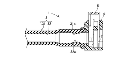
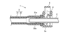
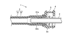
本実施形態の配管接続構造の概要について、図1A~図1Dを参照して説明する。図1Cに示すように、配管接続構造は、例えば自動車のガソリン燃料の配管1を構成し、パイプ体2と樹脂チューブ3との連結部位に相当する。配管1は、図1Cに示すように、パイプ体2と、樹脂チューブ3と、リテーナ4と、チェッカー5を備える。
(配管接続構造の概要)
本実施形態の配管接続構造の概要について、図1A~図1Dを参照して説明する。図1Cに示すように、配管接続構造は、例えば自動車のガソリン燃料の配管1を構成し、パイプ体2と樹脂チューブ3との連結部位に相当する。配管1は、図1Cに示すように、パイプ体2と、樹脂チューブ3と、リテーナ4と、チェッカー5を備える。
図1Aの初期状態の図に示すように、樹脂チューブ3とリテーナ4が連結されており、チェッカー5がリテーナ4に装着されている。この状態から、図1Bのパイプ体挿入状態の図に示すように、リテーナ4にパイプ体2を挿入する。続いて、図1Cの確認状態の図に示すように、チェッカー5を押し込むことで、パイプ体2がリテーナ4における正規位置に挿入されていることを確認する。そして、図1Dのリリース状態の図に示すように、チェッカー5をさらに押し込むことで、リテーナ4がリリース状態になり、パイプ体2をリテーナ4から引き抜くことができる。
以下に、各部の詳細構成について説明する。なお、リテーナ4およびチェッカー5は、特許第4937426号公報に記載の第二ハウジング(30)およびチェッカー(50)とほぼ同様の構成を備える。
(各部の詳細構成)
(パイプ体の詳細構成)
パイプ体2は、図1Bに示すように、金属製で筒状に形成されており、先端から離れた位置に径方向外方に突出する環状突部2aを備える。パイプ体2の先端は、面取形成されている。
(パイプ体の詳細構成)
パイプ体2は、図1Bに示すように、金属製で筒状に形成されており、先端から離れた位置に径方向外方に突出する環状突部2aを備える。パイプ体2の先端は、面取形成されている。
(樹脂チューブの詳細構成)
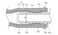
樹脂チューブ3の詳細構成について、図2Aおよび図2Bを参照して説明する。図2Aに示すように、樹脂チューブ3は、押出成形により全長に亘って多層構造に形成される。本実施形態においては、樹脂チューブ3は、外層31と内層32の2層構造とする。外層31は、相対的に弾性率が大きく、内層32は、相対的に弾性率が小さい。つまり、外層31は、内層32より硬い。そして、外層31および内層32は、押出成形によって一体的に接着した状態で成形される。押出成形を適用することにより、多層構造の樹脂チューブ3を非常に容易に成形できる。
樹脂チューブ3の詳細構成について、図2Aおよび図2Bを参照して説明する。図2Aに示すように、樹脂チューブ3は、押出成形により全長に亘って多層構造に形成される。本実施形態においては、樹脂チューブ3は、外層31と内層32の2層構造とする。外層31は、相対的に弾性率が大きく、内層32は、相対的に弾性率が小さい。つまり、外層31は、内層32より硬い。そして、外層31および内層32は、押出成形によって一体的に接着した状態で成形される。押出成形を適用することにより、多層構造の樹脂チューブ3を非常に容易に成形できる。
外層31は、熱可塑性樹脂により形成され、内層32は、熱可塑性エラストマーにより形成される。例えば、外層31は、宇部興産株式会社製の「UBESTA(登録商標)3030JI5L」により形成される。また、内層32は、例えば、宇部興産株式会社製の「UBESTA XPA(登録商標)9055X1」により形成される。例えば、外層31の弾性率は、400MPaであり、内層32の弾性率は、260MPaである。
さらに、外層31のうち樹脂チューブ3の開口端から僅かに離れた位置には、径方向内方に突出する環状の主突起31aが設けられている。この主突起31aの最小内径D31aは、パイプ体2の環状突部2aより先端側部分の円筒外周面の外径Dp(以下、パイプ先端外径と称する)より大きい。
主突起31aの縦断面(軸方向断面)は、ほぼ円弧形状に形成されている。つまり、主突起31aのうち開口側(パイプ体2の挿入側)および反開口側は、いずれも中心軸Xに対して傾斜している。換言すると、主突起31aのうち挿入側の接線(外層接線)は、中心軸Xに対して傾斜している。さらに、主突起31aのうち反挿入側の外層接線も、中心軸Xに対して傾斜している。なお、ここでは、主突起31aの縦断面を円弧形状としたが、台形形状としてもよい。
さらに、外層31のうち樹脂チューブ3の開口端には、径方向外方に突出する外突起31bが形成されている。外突起31bは、主突起31aよりも、樹脂チューブ3の開口側に位置している。
内層32は、樹脂チューブ3の全長に亘って、外層31の内周面形状に倣うように形成されている。本実施形態においては、内層32は、ほぼ同じ厚みに形成される。つまり、内層32のうち外層31の主突起31aに対応する部位32aが、径方向内方に突出する。以下、内層32の当該部位32aを、内層突起と称する。さらに、内層突起32aのうち開口側の内層接線L1および反開口側の内層接線L2は、いずれも中心軸Xに対して傾斜している。内層突起32aの最小内径D32aは、パイプ先端外径Dpより小さい。これに対して、内層突起32aの軸方向の両隣部位の円筒内周面部32b,32cの内径D32b,D32cは、パイプ先端外径Dpより大きい。
ここで、内層32は同じ厚みである必要はなく、以下を満たせば、異なる厚みであっても良い。すなわち、内層突起32aが形成され、内層突起32aの最小内径D32aがパイプ先端外径Dpより小さく、内層突起32aの軸方向両側の円筒内周面部32b,32cの内径D32b,D32cがパイプ先端外径Dpより大きいことを満たせばよい。
上記の樹脂チューブ3の開口側からパイプ体2を挿入すると、図2Bに示すようになる。ここで、内層突起32aより開口側の円筒内周面部32bの内径D32bは、パイプ先端外径Dpより大きい。従って、パイプ体2を容易に樹脂チューブ3の中で挿入できる。さらに、内層突起32aの最小内径D32aがパイプ先端外径Dpより小さいため、パイプ体2を挿入すると、パイプ体2の先端が内層突起32aの傾斜面に接触する。パイプ体2が内層突起32aの傾斜面に接触するため、パイプ体2のさらなる挿入が比較的容易である。
ここで、外層31の主突起31aの最小内径D31aがパイプ先端外径Dpより大きく、内層32の弾性率が、外層31の弾性率より小さい。従って、パイプ体2がさらに挿入されると、内層突起32aが、パイプ体2と外層31の主突起31aとにより径方向に圧縮される。内層突起32aより反開口側の円筒内周面部32cの内径D32cは、パイプ先端外径Dpより大きい。そのため、パイプ体2の先端と内層32との間には隙間が形成される。
このように、内層突起32aが外層31の主突起31aとパイプ体2とにより圧縮されることで、内層突起32aがシール性能を発揮する。さらに、内層突起32aは、外層31の主突起31aが設けられている部位に対応する。つまり、内層32において、外層31の主突起31aに対応する局所的な部位が圧縮する。このように、内層突起32aによって、高いシール性能を発揮できる。特に、内層32は熱可塑性エラストマーにより形成されることで、内層突起32aの弾性変形によって、より確実に高いシール性能を発揮できる。
また、外層31と内層32は、接着されている。これにより、外層31と内層32とが軸方向に相対的にずれることを抑制できる。その結果、パイプ体2が樹脂チューブ3に対して軸方向にずれる力が作用したとしても、外層31の主突起31aが内層突起32aを確実に圧縮させることができる。その結果、安定したシール性能を発揮できる。
(リテーナの詳細構成)
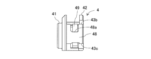
次に、リテーナ4の詳細構成について、図3A~図3Fを参照して説明する。リテーナ4は、チューブ係止部41と、リテーナ本体42と、リテーナ拡径弾性変形爪49とを備える。チューブ係止部41は、筒状に形成されており、図3Cに示すように、チューブ係止部41の内周面には環状溝41aが形成される。環状溝41aは、樹脂チューブ3の外層31の外突起31bが嵌め込まれる。このようにして、リテーナ4と樹脂チューブ3とが連結される。ここで、リテーナ4のチューブ係止部41と樹脂チューブ3の外層31は、凹凸の引っ掛かりに加えて、溶着や接着剤などにより接着される。
次に、リテーナ4の詳細構成について、図3A~図3Fを参照して説明する。リテーナ4は、チューブ係止部41と、リテーナ本体42と、リテーナ拡径弾性変形爪49とを備える。チューブ係止部41は、筒状に形成されており、図3Cに示すように、チューブ係止部41の内周面には環状溝41aが形成される。環状溝41aは、樹脂チューブ3の外層31の外突起31bが嵌め込まれる。このようにして、リテーナ4と樹脂チューブ3とが連結される。ここで、リテーナ4のチューブ係止部41と樹脂チューブ3の外層31は、凹凸の引っ掛かりに加えて、溶着や接着剤などにより接着される。
リテーナ本体42は、チューブ係止部41に一体的に形成され、リテーナ拡径弾性変形爪49に区別する意味で、変形しない部分である。このリテーナ本体42は、開口端座部材43と、下部連結部材44と、第一係止部45と、第二係止部46と、ガイド部47と、ストッパ48とを備える。開口端座部材43は、チューブ係止部41から軸方向に距離を隔てて配置される。開口端座部材43には、パイプ体2の環状突部2aを通過可能な大きさの中心孔43aが形成されている。
さらに、図3Dに示すように、開口端座部材43を軸方向から見て中心孔43aの図3Dの左右両側に、第二係止部46としての一対の係止穴(以下、「第二係止部46」と称する)が形成されている。一対の第二係止部46,46は、軸方向に貫通形成されている。一対の第二係止部46,46は、図1Aに示す初期状態において、チェッカー5の軸方向弾性変形爪52,52の先端突起52a,52bが引っ掛かる。
また、図3Dに示すように、開口端座部材43の外周面のうち一対の第二係止部46,46のそれぞれの上方には、平面座を形成する一対の上方切欠43b,43bが形成されている。一対の上方切欠43b,43bは、図1Aに示す初期状態とするために、チェッカー5の軸方向弾性変形爪52,52の初期位置決めを行うためのものである。つまり、一対の上方切欠43b,43bは、チェッカー5をリテーナ本体42に対して装着しやすくするための切欠である。
また、図3Dに示すように、開口端座部材43の外周面のうち一対の第二係止部46,46のそれぞれの下方には、平面座を形成する一対の下方切欠43c,43cが形成されている。一対の下方切欠43c,43cは、図1Cに示す係止確認完了状態において、チェッカー5の軸方向弾性変形爪52,52の位置決めを行うためのものである。下部連結部材44は、図3C,図3Eおよび図3Fに示すように、チューブ係止部41の下部と開口端座部材43の下部とを軸方向に連結する部分である。
第一係止部45は、図3Fに示すように、上方に向かって開口する半円弧形状に形成されている。この第一係止部45は、図3Cに示すように、下部連結部材44の上側面のうち、チューブ係止部41側に設けられている。そして、第一係止部45は、図3Fの二点鎖線にて示すパイプ体2の環状突部2aに干渉しない位置に設けられている。この第一係止部45の両端は鋭角状に形成されており、第一係止部45の図3Fの左右側面は鉛直平面状に形成されている。
ガイド部47は、図3B,図3C,図3Eおよび図3Fに示すように、チューブ係止部41の上側と開口端座部材43の上側とを連結する。このガイド部47は、図3Fの二点鎖線にて示すパイプ体2の環状突部2aに干渉しない位置に設けられている。
一対のストッパ48,48は、図3A,図3Eおよび図3Fに示すように、チューブ係止部41の中心孔の両横位置(図3E,図3Fの左右側)と開口端座部材43の中心孔43aの両横位置とをそれぞれ連結する。一対のストッパ48,48は、図3Fの二点鎖線にて示すパイプ体2の環状突部2aに干渉しない位置に設けられている。さらに、図3Aに示すように、一対のストッパ48,48のうち軸方向中央部分の上方側に切欠48aが形成されている。この切欠48aは、図1Bに示すパイプ体挿入状態において、リテーナ4のリテーナ拡径弾性変形爪49の拡径を許容すると共に、拡径量が設定量に到達した場合にリテーナ4のリテーナ拡径弾性変形爪49の拡径を規制する機能を有する。
リテーナ4のリテーナ拡径弾性変形爪49は、図3Eに示すように、上方に向かって開口するC字形状に形成されている。このリテーナ拡径弾性変形爪49は、弾性変形により拡径可能である。このリテーナ拡径弾性変形爪49は、図3Cに示すように、下部連結部材44の上側面のうち、軸方向のほぼ中央部に設けられている。つまり、リテーナ拡径弾性変形爪49は、開口端座部材43と第一係止部45との軸方向間に設けられている。
そして、リテーナ拡径弾性変形爪49は、図3Eに示すように、拡径していない状態において、図3Eの二点鎖線にて示すパイプ体2の環状突部2aに干渉する位置に設けられている。ただし、リテーナ拡径弾性変形爪49が拡径することによりパイプ体2の環状突部2aを通過可能とする。つまり、リテーナ拡径弾性変形爪49の軸方向位置をパイプ体2の環状突部2aが通過した後に、リテーナ拡径弾性変形爪49が形状復帰することにより、リテーナ拡径弾性変形爪49は、パイプ体2の環状突部2aに対して軸方向に係止する機能を発揮する。
さらに、リテーナ拡径弾性変形爪49の先端面49a,49bは、図3Eに示すように、内側に向かって傾斜する形状に形成されている。これは、リテーナ拡径弾性変形爪49の先端面49a,49bがチェッカー5のリリース部55,55によって押された場合に、リテーナ拡径弾性変形爪49が拡径するようにするためである。また、リテーナ拡径弾性変形爪49の先端側のうちパイプ体2の挿入側の端面49c,49dは、図3Bに示すように、パイプ体2の挿入側(図3Bの右側)から、パイプ体2の反挿入側(図3Bの左側)に向かって幅狭となるように傾斜形成されている。このように、端面49c,49dを傾斜形成することで、パイプ体2の環状突部2aがリテーナ拡径弾性変形爪49を通過しようとする際に、容易に拡径できるようになる。
(チェッカーの詳細構成)
次に、チェッカー5の詳細構成について、図4A~図4Dを参照して説明する。チェッカー5は、上述した「配管接続構造の概要」欄にて説明したように、パイプ体2の環状突部2aがリテーナ4における正規位置に挿入されていることを確認するための部材である。チェッカー5は、チェッカー拡径弾性変形爪51と、軸方向弾性変形爪52と、隙間介在部材53と、ガイド部54と、リリース部55とを備えて構成される。
次に、チェッカー5の詳細構成について、図4A~図4Dを参照して説明する。チェッカー5は、上述した「配管接続構造の概要」欄にて説明したように、パイプ体2の環状突部2aがリテーナ4における正規位置に挿入されていることを確認するための部材である。チェッカー5は、チェッカー拡径弾性変形爪51と、軸方向弾性変形爪52と、隙間介在部材53と、ガイド部54と、リリース部55とを備えて構成される。
チェッカー拡径弾性変形爪51は、図4Cに示すように、弾性変形により拡径可能なC字形状に形成されている。チェッカー拡径弾性変形爪51の両先端には、内側に向かって突出する突起51a,51bが形成されている。チェッカー拡径弾性変形爪51は、拡径していない状態にてリテーナ4の第一係止部45に係止されることで、チェッカー5はリテーナ本体42に対するスライド動作を規制される。また、チェッカー拡径弾性変形爪51は、リテーナ拡径弾性変形爪49を通過した後のパイプ体2の環状突部2aにより拡径される。そして、チェッカー拡径弾性変形爪51が拡径した状態にて第一係止部45に対する係止が解除されて、チェッカー5はリテーナ本体42に対してスライド動作可能な状態となる。
一対の軸方向弾性変形爪52,52は、チェッカー拡径弾性変形爪51の基部51cに設けられている。一対の軸方向弾性変形爪52,52は、チェッカー拡径弾性変形爪51に対して図4Aの左右方向(図1Aの軸方向に相当)に距離を隔てて設けられている。そして、軸方向弾性変形爪52,52の先端側が、図4Aの左右方向に撓み変形可能に形成されている。軸方向弾性変形爪52,52の先端には、図4Aの右側に向かって突出する突起52a,52bが形成されている。
また、軸方向弾性変形爪52,52は、リテーナ拡径弾性変形爪49が拡径している状態にてリテーナ拡径弾性変形爪49により撓み変形が規制されることで、リテーナ本体42の第二係止部46に係止された状態を維持する。さらに、軸方向弾性変形爪52,52は、リテーナ本体42の第二係止部46に係止されることで、チェッカー5は、リテーナ本体42に対するスライド動作を規制される。また、軸方向弾性変形爪52,52は、リテーナ拡径弾性変形爪49が形状復帰した状態にてリテーナ本体42の第二係止部46に対する係止が解除可能となることで、チェッカー5は、リテーナ本体42に対してスライド動作可能な状態となる。
一対の隙間介在部材53,53は、図4Bに示すように、それぞれの軸方向弾性変形爪52,52の径方向内側にスリット53a,53bを介して形成される。一対の隙間介在部材53,53は、図1Aに示す初期状態から図1Cに示す確認状態の間、リテーナ本体42の開口端座部材43とリテーナ拡径弾性変形爪49との軸方向隙間に介在するものである。
ガイド部54,54は、図4Cに示すように、チェッカー拡径弾性変形爪51の基部51cに設けられ、チェッカー拡径弾性変形爪51のC字形状の内側に形成されている。これらのガイド部54,54は、リテーナ4のガイド部47の幅に対応する距離を隔てて形成されている。このチェッカー5のガイド部54,54は、リテーナ4のガイド部47と係合することにより、リテーナ4とチェッカー5との相対的な回転を規制し、図の上下方向への相対的なスライド動作をガイドする機能を有する。
リリース部55,55は、図4Aおよび図4Dに示すように、チェッカー拡径弾性変形爪51の基部51cに設けられ、軸方向弾性変形爪52とガイド部54との軸方向間に形成されている。このリリース部55,55は、図4Dに示すように、内側から外側に向かって傾斜形成されている。このリリース部55,55は、リテーナ拡径弾性変形爪49の先端面49a,49bの傾斜に対応する形状に形成されている。リリース部55,55は、チェッカー5がリテーナ4に対してスライド動作することにより、リテーナ拡径弾性変形爪49を拡径させる。
なお、リテーナ4とチェッカー5の動作については、特許第4937426号公報に記載の第二ハウジング(30)およびチェッカー(50)と同様の動作であるため、詳細な説明を省略する。
以上説明したように、樹脂チューブ3自身が、シール部材としての機能を有する。従って、本実施形態によれば、例えばOリングなど、別部材としてのシール部材を用いることなく、パイプ体2と樹脂チューブ3との間における高いシール性を確保できる。その結果、部品点数の低減を図ることができ、組付工数の低減を図ることができる。
さらに、配管1は、樹脂チューブ3と別体のリテーナ4を用いている。そして、リテーナ4がパイプ体2の抜けを規制している。仮に、樹脂チューブ3がパイプ体2に引っ掛かる構成の場合には、パイプ体2の抜き差し回数が多くなれば、樹脂チューブ3の引っ掛かり力が低下してしまう。そのため、パイプ体2の抜け規制機能は、樹脂チューブ3とは異なる部材に持たせる方が良い。そこで、樹脂チューブ3と別体のリテーナ4を用いることで、樹脂チューブ3がパイプ体2の環状突部2aに引っ掛かることなく、パイプ体2の抜き差しを行ったとしても、樹脂チューブ3は何ら影響を受けない。従って、樹脂チューブ3としての耐久性を向上させることができる。
<第二実施形態>
第二実施形態の樹脂チューブについて、図5A~図5Bを参照して説明する。図5Aに示すように、外層31は、主突起31aの軸方向両側に、径方向内方に突出する環状の副突起31c,31dを備える。副突起31c,31dの突出高さは、主突起31aの突出高さより低い。つまり、副突起31c,31dの最小内径D31c,D31dは、主突起31aの最小内径D31aより大きい。また、副突起31c,31dの軸方向幅は、主突起31aに比べてかなり小さい。つまり、副突起31c,31dは、微小な突起である。
第二実施形態の樹脂チューブについて、図5A~図5Bを参照して説明する。図5Aに示すように、外層31は、主突起31aの軸方向両側に、径方向内方に突出する環状の副突起31c,31dを備える。副突起31c,31dの突出高さは、主突起31aの突出高さより低い。つまり、副突起31c,31dの最小内径D31c,D31dは、主突起31aの最小内径D31aより大きい。また、副突起31c,31dの軸方向幅は、主突起31aに比べてかなり小さい。つまり、副突起31c,31dは、微小な突起である。
内層32は、上記実施形態と同様に、外層31の内周面形状に倣うように形成されている。つまり、内層32の内周面には、外層31の副突起31c,31dに対応する部位32d,32e(以下、内層小突起と称する)が、径方向に突出する。このとき、内層小突起32d,32eの最小内径D32d,D32eは、内層突起32aの最小内径D32aより大きく、かつ、パイプ体2のパイプ先端外径Dpより大きい。従って、パイプ体2が樹脂チューブ3に挿入されたときに、パイプ体2と内層小突起32d,32eとの間に隙間が形成される。
さらに、内層小突起32dの開口側の円筒内周面部32bの内径D32b、および、内層小突起32eの反開口側の円筒内周面部32cの内径D32cは、内層小突起32d,32eの最小内径D32d,D32eより大きい。従って、当然に、円筒内周面部32b,32cは、パイプ体2に接触しない。
上記の樹脂チューブ3の開口側からパイプ体2を挿入すると、図5Bに示すようになる。内層突起32aが、パイプ体2と外層31の主突起31aとにより径方向に圧縮される。このとき、内層突起32aは、圧縮変形されるだけでなく、軸方向両側の空間へ逃げようとする。しかし、外層31の主突起31aの軸方向両側には、副突起31c,31dが形成されている。従って、副突起31c,31dは、内層小突起32d,32eの部分の軸方向両側への逃げを抑制する。さらに、副突起31c,31dの内周面側に内層小突起32d,32eが形成されていることによっても、内層突起32aが軸方向へ逃げにくい状態となる。
このように、外層31の両副突起31c,31dおよび内層小突起32d,32eが、内層突起32aの軸方向への逃げを抑制することによって、内層突起32aの圧縮率が高くなり、結果として高いシール性能を発揮できる。ここで、内層小突起32d,32eは、パイプ体2に接触しないため、シール性能を発揮しない。つまり、圧縮によりシール機能を発揮する主突起31aおよび内層突起32aと、内層突起32aの逃げ抑制機能を発揮する副突起31c,31dおよび内層小突起32d,32eとを異なる部位に分けることで、全体として高いシール性能を発揮できる。
1:配管、 2:パイプ体(相手材)、 2a:環状突部、 3:樹脂チューブ、 4:リテーナ、 5:チェッカー、 31:外層、 31a:主突起、 31b:外突起(係止対)、 31c,31d:副突起、 32:内層、 32a:内層突起、 32d,32e:内層小突起、 32d,32e:内層32のうち副突起31c,31dに対応する部位、 D32d,D32e:内層32の部位32d,32eの内径、 41:チューブ係止部、 41a:環状溝(係止対)、 L1,L2:内層接線、 X:中心軸、 Dp:パイプ体2の外径
Claims (9)
- 開口端から相手材が挿入される樹脂チューブであって、
外層と前記外層より弾性率の小さな内層とを備え、
前記外層は、前記樹脂チューブの開口端側に径方向内方に突出する環状の主突起を備え、
前記内層は、前記相手材が前記樹脂チューブに挿入された時に、前記主突起と前記相手材とにより圧縮される、樹脂チューブ。 - 前記内層は、熱可塑性エラストマーにより形成される、請求項1の樹脂チューブ。
- 前記外層と前記内層は、接着されている、請求項1または2の樹脂チューブ。
- 前記外層および前記内層は、押出成形により一体的に接着した状態で成形される、請求項3の樹脂チューブ。
- 軸方向断面における前記内層の内周面における接線を内層接線と定義し、
前記主突起のうち前記相手材の挿入側に対応する前記内層接線は、中心軸に対して傾斜している、請求項1~4の何れか一項の樹脂チューブ。 - 前記外層は、前記主突起の軸方向両側に、径方向内方に突出する環状の副突起を備え、
前記副突起は、前記内層のうち前記主突起に対応する部位が圧縮される際に軸方向への逃げを抑制する、請求項1~5の何れか一項の樹脂チューブ。 - 前記副突起の高さは、前記主突起の高さより低く形成され、
前記内層のうち前記副突起に対応する部位の内径は、前記相手材の外径より大きく形成される、請求項6の樹脂チューブ。 - 先端から離れた位置に径方向外方に突出する環状突部を備えるパイプ体と、
開口端から前記パイプ体の先端側が挿入される樹脂チューブと、
筒状に形成され、前記樹脂チューブの軸方向端に連結され、かつ、前記パイプ体が挿入された状態において前記パイプ体の前記環状突部に係止することで前記パイプ体の抜けを規制するリテーナと、
を備え、
前記樹脂チューブは、外層と前記外層より弾性率の小さな内層とを備え、
前記外層は、前記樹脂チューブの開口端側に径方向内方に突出する環状の主突起を備え、
前記内層は、前記パイプ体が前記樹脂チューブに挿入された時に、前記主突起と前記パイプ体とにより圧縮される、配管接続構造。 - 前記樹脂チューブの外周面および前記リテーナの内周面は、相互に軸方向に引っ掛け合う係止対を備え、
前記係止対によって、前記樹脂チューブと前記リテーナは連結される、請求項8の配管接続構造。
Applications Claiming Priority (2)
| Application Number | Priority Date | Filing Date | Title |
|---|---|---|---|
| JP2012278335A JP2014122657A (ja) | 2012-12-20 | 2012-12-20 | 樹脂チューブおよび配管接続構造 |
| JP2012-278335 | 2012-12-20 |
Publications (1)
| Publication Number | Publication Date |
|---|---|
| WO2014097746A1 true WO2014097746A1 (ja) | 2014-06-26 |
Family
ID=50978093
Family Applications (1)
| Application Number | Title | Priority Date | Filing Date |
|---|---|---|---|
| PCT/JP2013/079191 Ceased WO2014097746A1 (ja) | 2012-12-20 | 2013-10-29 | 樹脂チューブおよび配管接続構造 |
Country Status (2)
| Country | Link |
|---|---|
| JP (1) | JP2014122657A (ja) |
| WO (1) | WO2014097746A1 (ja) |
Families Citing this family (1)
| Publication number | Priority date | Publication date | Assignee | Title |
|---|---|---|---|---|
| JP6886275B2 (ja) * | 2016-11-28 | 2021-06-16 | 住友理工株式会社 | 脈動低減ホース |
Citations (4)
| Publication number | Priority date | Publication date | Assignee | Title |
|---|---|---|---|---|
| JPS57193482U (ja) * | 1981-06-03 | 1982-12-08 | ||
| JP2006124665A (ja) * | 2004-09-28 | 2006-05-18 | Tokai Rubber Ind Ltd | シール層付ホースとその直付け組付品及びシール層付ホースの製造方法 |
| JP2006234024A (ja) * | 2005-02-23 | 2006-09-07 | Toyoda Gosei Co Ltd | コネクタ |
| JP2008133897A (ja) * | 2006-11-28 | 2008-06-12 | Toyox Co Ltd | 飲料用ホース |
-
2012
- 2012-12-20 JP JP2012278335A patent/JP2014122657A/ja active Pending
-
2013
- 2013-10-29 WO PCT/JP2013/079191 patent/WO2014097746A1/ja not_active Ceased
Patent Citations (4)
| Publication number | Priority date | Publication date | Assignee | Title |
|---|---|---|---|---|
| JPS57193482U (ja) * | 1981-06-03 | 1982-12-08 | ||
| JP2006124665A (ja) * | 2004-09-28 | 2006-05-18 | Tokai Rubber Ind Ltd | シール層付ホースとその直付け組付品及びシール層付ホースの製造方法 |
| JP2006234024A (ja) * | 2005-02-23 | 2006-09-07 | Toyoda Gosei Co Ltd | コネクタ |
| JP2008133897A (ja) * | 2006-11-28 | 2008-06-12 | Toyox Co Ltd | 飲料用ホース |
Also Published As
| Publication number | Publication date |
|---|---|
| JP2014122657A (ja) | 2014-07-03 |
Similar Documents
| Publication | Publication Date | Title |
|---|---|---|
| JP6067366B2 (ja) | 配管接続構造 | |
| US7810848B2 (en) | Pipe joint and pipe joint structure having the same and method of using the same | |
| JP4937426B1 (ja) | クイックコネクタ | |
| CN100467930C (zh) | 快速连接器 | |
| CN105339719B (zh) | 锁定快速连接组件 | |
| US7837234B2 (en) | Pipe joint unit and method of manufacturing the same | |
| KR101287912B1 (ko) | 자동차용 배기 파이프 및 배기 시스템 | |
| CN107429868B (zh) | 快速连接器 | |
| US20100225108A1 (en) | Connecting assembly with a first pipe connection and a second pipe connection and a lock ring assembly for a connecting assembly of this type | |
| CN101048613A (zh) | 抗拉插塞连接器 | |
| WO2002055918A1 (en) | Pipe joint | |
| WO2012077654A1 (ja) | 管体構造 | |
| US7429065B2 (en) | Hose and tube assembly | |
| WO2014097746A1 (ja) | 樹脂チューブおよび配管接続構造 | |
| CN101421552B (zh) | 管接头 | |
| JP4402498B2 (ja) | 管継手 | |
| CN100473885C (zh) | 抗高压软管 | |
| CN114161104B (zh) | 中间轴轴向保持装置 | |
| US20060141869A1 (en) | Tube for transporting fluid | |
| CN113859350A (zh) | 中间轴轴向保持装置 | |
| JP3988191B2 (ja) | 半嵌合防止機能を有するクイックコネクタ | |
| CN1878980A (zh) | 快速连接器 | |
| JPH08121666A (ja) | 継手部をもつホース | |
| JP2009085346A (ja) | クイックコネクタ | |
| JP2012013200A (ja) | 配管接続構造 |
Legal Events
| Date | Code | Title | Description |
|---|---|---|---|
| 121 | Ep: the epo has been informed by wipo that ep was designated in this application |
Ref document number: 13864075 Country of ref document: EP Kind code of ref document: A1 |
|
| NENP | Non-entry into the national phase |
Ref country code: DE |
|
| 122 | Ep: pct application non-entry in european phase |
Ref document number: 13864075 Country of ref document: EP Kind code of ref document: A1 |