WO2014091948A1 - フィンアンドチューブ型熱交換器および空気調和機 - Google Patents
フィンアンドチューブ型熱交換器および空気調和機 Download PDFInfo
- Publication number
- WO2014091948A1 WO2014091948A1 PCT/JP2013/082218 JP2013082218W WO2014091948A1 WO 2014091948 A1 WO2014091948 A1 WO 2014091948A1 JP 2013082218 W JP2013082218 W JP 2013082218W WO 2014091948 A1 WO2014091948 A1 WO 2014091948A1
- Authority
- WO
- WIPO (PCT)
- Prior art keywords
- heat exchanger
- refrigerant
- fluid
- fin
- air conditioner
- Prior art date
- Legal status (The legal status is an assumption and is not a legal conclusion. Google has not performed a legal analysis and makes no representation as to the accuracy of the status listed.)
- Ceased
Links
Images





Classifications
-
- F—MECHANICAL ENGINEERING; LIGHTING; HEATING; WEAPONS; BLASTING
- F28—HEAT EXCHANGE IN GENERAL
- F28F—DETAILS OF HEAT-EXCHANGE AND HEAT-TRANSFER APPARATUS, OF GENERAL APPLICATION
- F28F1/00—Tubular elements; Assemblies of tubular elements
- F28F1/10—Tubular elements and assemblies thereof with means for increasing heat-transfer area, e.g. with fins, with projections, with recesses
- F28F1/12—Tubular elements and assemblies thereof with means for increasing heat-transfer area, e.g. with fins, with projections, with recesses the means being only outside the tubular element
- F28F1/24—Tubular elements and assemblies thereof with means for increasing heat-transfer area, e.g. with fins, with projections, with recesses the means being only outside the tubular element and extending transversely
- F28F1/32—Tubular elements and assemblies thereof with means for increasing heat-transfer area, e.g. with fins, with projections, with recesses the means being only outside the tubular element and extending transversely the means having portions engaging further tubular elements
-
- F—MECHANICAL ENGINEERING; LIGHTING; HEATING; WEAPONS; BLASTING
- F24—HEATING; RANGES; VENTILATING
- F24D—DOMESTIC- OR SPACE-HEATING SYSTEMS, e.g. CENTRAL HEATING SYSTEMS; DOMESTIC HOT-WATER SUPPLY SYSTEMS; ELEMENTS OR COMPONENTS THEREFOR
- F24D17/00—Domestic hot-water supply systems
- F24D17/02—Domestic hot-water supply systems using heat pumps
-
- F—MECHANICAL ENGINEERING; LIGHTING; HEATING; WEAPONS; BLASTING
- F24—HEATING; RANGES; VENTILATING
- F24F—AIR-CONDITIONING; AIR-HUMIDIFICATION; VENTILATION; USE OF AIR CURRENTS FOR SCREENING
- F24F1/00—Room units for air-conditioning, e.g. separate or self-contained units or units receiving primary air from a central station
- F24F1/06—Separate outdoor units, e.g. outdoor unit to be linked to a separate room comprising a compressor and a heat exchanger
- F24F1/14—Heat exchangers specially adapted for separate outdoor units
-
- F—MECHANICAL ENGINEERING; LIGHTING; HEATING; WEAPONS; BLASTING
- F25—REFRIGERATION OR COOLING; COMBINED HEATING AND REFRIGERATION SYSTEMS; HEAT PUMP SYSTEMS; MANUFACTURE OR STORAGE OF ICE; LIQUEFACTION SOLIDIFICATION OF GASES
- F25B—REFRIGERATION MACHINES, PLANTS OR SYSTEMS; COMBINED HEATING AND REFRIGERATION SYSTEMS; HEAT PUMP SYSTEMS
- F25B39/00—Evaporators; Condensers
- F25B39/04—Condensers
-
- F—MECHANICAL ENGINEERING; LIGHTING; HEATING; WEAPONS; BLASTING
- F28—HEAT EXCHANGE IN GENERAL
- F28D—HEAT-EXCHANGE APPARATUS, NOT PROVIDED FOR IN ANOTHER SUBCLASS, IN WHICH THE HEAT-EXCHANGE MEDIA DO NOT COME INTO DIRECT CONTACT
- F28D1/00—Heat-exchange apparatus having stationary conduit assemblies for one heat-exchange medium only, the media being in contact with different sides of the conduit wall, in which the other heat-exchange medium is a large body of fluid, e.g. domestic or motor car radiators
- F28D1/02—Heat-exchange apparatus having stationary conduit assemblies for one heat-exchange medium only, the media being in contact with different sides of the conduit wall, in which the other heat-exchange medium is a large body of fluid, e.g. domestic or motor car radiators with heat-exchange conduits immersed in the body of fluid
- F28D1/04—Heat-exchange apparatus having stationary conduit assemblies for one heat-exchange medium only, the media being in contact with different sides of the conduit wall, in which the other heat-exchange medium is a large body of fluid, e.g. domestic or motor car radiators with heat-exchange conduits immersed in the body of fluid with tubular conduits
- F28D1/047—Heat-exchange apparatus having stationary conduit assemblies for one heat-exchange medium only, the media being in contact with different sides of the conduit wall, in which the other heat-exchange medium is a large body of fluid, e.g. domestic or motor car radiators with heat-exchange conduits immersed in the body of fluid with tubular conduits the conduits being bent, e.g. in a serpentine or zig-zag
- F28D1/0477—Heat-exchange apparatus having stationary conduit assemblies for one heat-exchange medium only, the media being in contact with different sides of the conduit wall, in which the other heat-exchange medium is a large body of fluid, e.g. domestic or motor car radiators with heat-exchange conduits immersed in the body of fluid with tubular conduits the conduits being bent, e.g. in a serpentine or zig-zag the conduits being bent in a serpentine or zig-zag
-
- F—MECHANICAL ENGINEERING; LIGHTING; HEATING; WEAPONS; BLASTING
- F24—HEATING; RANGES; VENTILATING
- F24D—DOMESTIC- OR SPACE-HEATING SYSTEMS, e.g. CENTRAL HEATING SYSTEMS; DOMESTIC HOT-WATER SUPPLY SYSTEMS; ELEMENTS OR COMPONENTS THEREFOR
- F24D2200/00—Heat sources or energy sources
- F24D2200/12—Heat pump
- F24D2200/123—Compression type heat pumps
-
- F—MECHANICAL ENGINEERING; LIGHTING; HEATING; WEAPONS; BLASTING
- F25—REFRIGERATION OR COOLING; COMBINED HEATING AND REFRIGERATION SYSTEMS; HEAT PUMP SYSTEMS; MANUFACTURE OR STORAGE OF ICE; LIQUEFACTION SOLIDIFICATION OF GASES
- F25B—REFRIGERATION MACHINES, PLANTS OR SYSTEMS; COMBINED HEATING AND REFRIGERATION SYSTEMS; HEAT PUMP SYSTEMS
- F25B2339/00—Details of evaporators; Details of condensers
- F25B2339/04—Details of condensers
- F25B2339/043—Condensers made by assembling plate-like or laminated elements
-
- F—MECHANICAL ENGINEERING; LIGHTING; HEATING; WEAPONS; BLASTING
- F25—REFRIGERATION OR COOLING; COMBINED HEATING AND REFRIGERATION SYSTEMS; HEAT PUMP SYSTEMS; MANUFACTURE OR STORAGE OF ICE; LIQUEFACTION SOLIDIFICATION OF GASES
- F25B—REFRIGERATION MACHINES, PLANTS OR SYSTEMS; COMBINED HEATING AND REFRIGERATION SYSTEMS; HEAT PUMP SYSTEMS
- F25B2339/00—Details of evaporators; Details of condensers
- F25B2339/04—Details of condensers
- F25B2339/047—Water-cooled condensers
-
- F—MECHANICAL ENGINEERING; LIGHTING; HEATING; WEAPONS; BLASTING
- F25—REFRIGERATION OR COOLING; COMBINED HEATING AND REFRIGERATION SYSTEMS; HEAT PUMP SYSTEMS; MANUFACTURE OR STORAGE OF ICE; LIQUEFACTION SOLIDIFICATION OF GASES
- F25B—REFRIGERATION MACHINES, PLANTS OR SYSTEMS; COMBINED HEATING AND REFRIGERATION SYSTEMS; HEAT PUMP SYSTEMS
- F25B6/00—Compression machines, plants or systems, with several condenser circuits
- F25B6/02—Compression machines, plants or systems, with several condenser circuits arranged in parallel
-
- Y—GENERAL TAGGING OF NEW TECHNOLOGICAL DEVELOPMENTS; GENERAL TAGGING OF CROSS-SECTIONAL TECHNOLOGIES SPANNING OVER SEVERAL SECTIONS OF THE IPC; TECHNICAL SUBJECTS COVERED BY FORMER USPC CROSS-REFERENCE ART COLLECTIONS [XRACs] AND DIGESTS
- Y02—TECHNOLOGIES OR APPLICATIONS FOR MITIGATION OR ADAPTATION AGAINST CLIMATE CHANGE
- Y02P—CLIMATE CHANGE MITIGATION TECHNOLOGIES IN THE PRODUCTION OR PROCESSING OF GOODS
- Y02P80/00—Climate change mitigation technologies for sector-wide applications
- Y02P80/10—Efficient use of energy, e.g. using compressed air or pressurized fluid as energy carrier
Definitions
- the present invention relates to a fin-and-tube heat exchanger and an air conditioner, and more specifically, a fin-and-tube heat exchanger for performing heat exchange between a refrigerant and a fluid to be heated, and such
- the present invention relates to an air conditioner including a fin-and-tube heat exchanger.
- Patent Document 1 Japanese Patent Application Laid-Open No. 2003-65602 discloses a heat pump bath water heater that is intended to have a small and compact shape (Patent Document 1).
- the heat pump bath water heater disclosed in Patent Document 1 is a water heater that heats water in a hot water storage tank and a bathtub using a refrigeration cycle, and heat is generated between the refrigerant circuit and the hot water circuit and between the refrigerant circuit and the bathtub circuit. It has a replaceable refrigerant water heat exchanger.
- a refrigerant water heat exchanger a multi-tube system in which a hot water supply circuit pipe and a bathtub circuit pipe are inserted into a refrigerant circuit pipe through which the refrigerant flows, or a refrigerant circuit pipe, a hot water supply pipe, and a bathtub circuit pipe
- the contact tube method is used that is fixed with brazing material.
- Japanese Utility Model Laid-Open No. 59-79778 discloses that the pressure loss during refrigerant circulation is kept small, the number of solenoid valves is reduced, and that heating / cooling / hot water supply operation can be performed only with an inexpensive one-way solenoid valve.
- a heat pump hot water supply / cooling / heating device for the purpose is disclosed (Patent Document 2).
- the heat pump hot water supply / cooling / heating device disclosed in Patent Literature 2 includes an outdoor heat exchanger and a hot water supply heat exchanger. During the cooling-only operation and the heating-only operation, the refrigerant is supplied to the outdoor heat exchanger, and during the hot-water cooling simultaneous operation and the hot-water supply independent operation, the refrigerant is supplied to the hot-water supply heat exchanger.
- Japanese Patent Laid-Open No. 58-66764 discloses a heat pump type air conditioner / heater that aims to provide a multi-function air conditioner in which a hot water supply function is added to a conventional room air conditioner combined with an air conditioner.
- Patent Document 3 The heat pump air-conditioning / heating water heater disclosed in Patent Document 3 includes an outdoor heat exchanger and a water heat exchanger. During the cooling operation and the heating operation, the refrigerant is supplied to the outdoor heat exchanger, and during the cooling / exhaust heat operation in which hot water is supplied by using the heat of condensation during cooling and during the dedicated hot water operation, the refrigerant is supplied to the water heat exchanger.
- Patent Document 1 As disclosed in Patent Document 1 described above, as a heat exchanger for hot water supply, a multiple pipe system in which another pipe is inserted into the pipe or a contact pipe system in which the pipe and the pipe are joined is used.
- these methods are advantageous in that heat exchange is performed with high efficiency, but there is a problem that the production method is complicated and expensive.
- an object of the present invention is to solve the above-described problems, and to provide a fin-and-tube heat exchanger and an air conditioner that are manufactured at a low cost.
- the fin-and-tube heat exchanger heats the heated fluid by exchanging heat between the refrigerant and the heated fluid.
- the fin-and-tube heat exchanger has a flat plate shape, a plurality of fins arranged at intervals, and a plurality of fins extending through the plurality of fins, perpendicular to the fins, and parallel to each other.
- multi-row piping arranged in a virtual plane.
- the multi-row pipe includes a fluid pipe through which a fluid to be heated flows and a refrigerant pipe through which a refrigerant flows.
- Each fin is formed from a single plate material in the direction in which the virtual planes are arranged.
- each fin is formed from a single plate in the direction of the virtual plane, heat exchange is efficiently performed between the fluid to be heated and the refrigerant. Is done.
- the heat exchanger for heating a to-be-heated fluid can be manufactured at low cost using the production facility of the conventional fin and tube type heat exchanger.
- a plurality of virtual planes are provided with a first plane and a second plane lined up at an interval from the first plane.
- the fluid piping and the refrigerant piping are routed in the first plane and the second plane, respectively.
- the heat exchanger can be manufactured at a lower cost by making the multi-row piping simple.
- the air conditioner according to the present invention has a function of heating the fluid to be heated.
- An air conditioner includes the fin-and-tube heat exchanger according to any one of the above, a refrigeration circuit constituting a heat pump cycle, and a fluid circuit through which a fluid to be heated flows.
- the refrigerant is supplied from the refrigeration circuit to the refrigerant pipe, and the fluid to be heated is supplied from the fluid circuit to the fluid pipe.
- an air conditioner having a function of heating a fluid to be heated can be widely spread by including a fin-and-tube heat exchanger manufactured at a low cost. .
- the air conditioner is provided on the path of the refrigeration circuit, and has an outdoor heat exchanger installed outside the fin and tube heat exchanger and a fan for supplying outdoor air to the outdoor heat exchanger.
- a detection unit that detects the flow of the heated fluid in the fluid circuit, and the fan is stopped when the flow of the heated fluid is detected by the detection unit, and the fan is stopped when the flow of the heated fluid is not detected.
- a controller to be driven.
- the air conditioner configured as described above, when the flow of the fluid to be heated is detected by the detection unit, heat is exchanged between the fluid to be heated and the refrigerant in the fin-and-tube heat exchanger.
- the fan for supplying outdoor air to the outer heat exchanger is stopped.
- a fan for supplying outdoor air to the outdoor heat exchanger in order to exchange heat between the outdoor air and the refrigerant in the outdoor heat exchanger Drive.
- the air conditioner further includes a compressor provided on the path of the refrigeration circuit for circulating the refrigerant, and an indoor unit installed indoors.
- the indoor unit includes an indoor heat exchanger provided on the path of the refrigeration circuit.
- the control unit is mounted inside the indoor unit.
- the compressor is arranged outdoors. The control unit controls the fan and the compressor.
- the control unit mounted on the indoor unit controls the outdoor compressor and the outdoor fan. Therefore, since it is not necessary to provide a control part in an outdoor side, the structure of an air conditioner can be simplified.
- the detection unit is arranged in a portion of the fluid circuit provided outside the room.
- the control unit need not be provided on the outdoor side, so that the configuration of the air conditioner can be simplified.
- the control unit includes first to fifth terminals, first and second switches, and a signal generation circuit that controls the first and second switches in response to signals from the detection unit.
- the first terminal is a terminal for supplying power from the power source to the fan.
- the second terminal is a terminal for inputting a signal from the detection unit to the signal generation circuit.
- the third terminal is a terminal for supplying power from the power source to the compressor.
- the fourth terminal is a neutral terminal of the power supply.
- the fifth terminal is a power supply ground terminal.
- the first switch is connected between the power supply and the first terminal.
- the second switch is connected between the power supply and the third terminal.
- the air conditioner further includes a terminal board including first and second power terminals, a signal terminal, a neutral terminal, and a ground terminal, first to fifth terminals of the control board, and a first power source of the terminal board. First to fifth wirings for connecting to a terminal, a signal terminal, a second power supply terminal, a neutral terminal, and a ground terminal, respectively.
- the first power supply terminal of the terminal board is connected to the fan.
- the second power supply terminal of the terminal board is connected to the compressor.
- the signal terminal of the terminal board is connected to the detection unit and receives a signal from the detection unit.
- the control board of the indoor unit and the outdoor terminal board can be electrically connected by five wires. Furthermore, the outdoor fan and the compressor can be controlled by a control unit provided in the indoor unit. Therefore, a control board is not required for the outdoor unit.
- the fin-and-tube heat exchanger and the outdoor heat exchanger are provided integrally.
- the outdoor unit of the air conditioner can be configured in a compact manner.
- the air conditioner further includes a compressor that is provided on the path of the refrigeration circuit and compresses the refrigerant supplied to the outdoor heat exchanger, and a pressure switch that is provided on the path of the refrigeration circuit and detects the pressure of the refrigerant.
- the control unit drives the fan when the flow of the fluid to be heated is detected by the detection unit, and when the pressure of the refrigerant is detected by the pressure switch to be a predetermined value or more.
- the air conditioner configured as described above, when the refrigerant pressure in the refrigeration circuit is equal to or higher than a predetermined value, the refrigerant is more actively cooled in the outdoor heat exchanger by driving the fan. To do. Thereby, it can suppress that an excessive load is applied to the compressor on a refrigerating circuit, and can improve the reliability of a compressor.
- FIG. 1 It is a figure which shows the circuit structure of the air conditioner with the hot water supply function in Embodiment 1 of this invention. It is a perspective view which shows the outdoor unit of the air conditioner in FIG. It is a perspective view which shows partially the water heat exchanger with which the air conditioner in FIG. 1 is provided. It is a front view which shows the water heat exchanger in FIG. It is a perspective view which shows the modification of the water heat exchanger shown in FIG. It is a block diagram which shows the structure of the air conditioner in FIG. It is the circuit diagram which showed the structure regarding control of the air conditioner in FIG. It is a figure which shows the circuit structure of the air conditioner with the hot water supply function in Embodiment 3 of this invention. It is a figure which shows the circuit structure of the air conditioner with the hot water supply function in Embodiment 4 of this invention. It is the circuit diagram which showed the structure regarding control of the air conditioner in FIG.
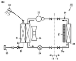
- FIG. 1 is a diagram showing a circuit configuration of an air conditioner with a hot water supply function according to Embodiment 1 of the present invention.
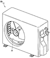
- FIG. 2 is a perspective view showing an outdoor unit of the air conditioner in FIG. 1.
- air conditioner 10 in the present embodiment has a hot water supply function.
- the air conditioner 10 is an air conditioner dedicated to cooling.
- the air conditioner 10 forms a heat pump cycle as its circuit configuration, and includes a refrigeration circuit 21 in which a refrigerant circulates and a hot water supply circuit 31 in which water (tap water in the present embodiment) as a fluid to be heated circulates. Have. The water flowing through the hot water supply circuit 31 is heated by heat exchange with the refrigerant circulating through the refrigeration circuit 21.
- the refrigerant for cooling the indoor space circulates in the refrigeration circuit 21.
- HC hydrocarbon
- HFC hydrofluorocarbon
- the refrigeration circuit 21 includes a refrigerant circulation path 21p that forms an annular circulation path, and a refrigerant branch path 21q that branches from the refrigerant circulation path 21p.
- the refrigeration circuit 21 is provided with an indoor heat exchanger (air-refrigerant heat exchanger) 25, an outdoor heat exchanger (air-refrigerant heat exchanger) 23, a compressor 22 and an expansion valve 24.
- the indoor heat exchanger 25, the outdoor heat exchanger 23, the compressor 22 and the expansion valve 24 are provided on the refrigerant circulation path 21p.
- the flow direction of the refrigerant during hot water supply is typically indicated by an arrow.
- the indoor heat exchanger 25 exchanges heat between the refrigerant circulating in the refrigeration circuit 21 and the air in the indoor space.
- the indoor side heat exchanger 25 is provided in the indoor unit 14 installed indoors.
- the indoor unit 14 is further provided with a fan 27 for supplying room air to the indoor heat exchanger 25.
- the fan 27 is a cross flow fan.
- the outdoor heat exchanger 23 performs heat exchange between the refrigerant circulating in the refrigeration circuit 21 and the outdoor air.
- the outdoor heat exchanger 23 is provided in the outdoor unit 12 installed outside.
- the outdoor unit 12 is further provided with a fan 26 for supplying outdoor air to the outdoor heat exchanger 23.
- the fan 26 is disposed so as to face the outdoor heat exchanger 23.
- the fan 26 is a propeller fan.
- the compressor 22 is disposed between the indoor heat exchanger 25 and the outdoor heat exchanger 23 on the refrigerant circulation path 21p.
- the compressor 22 compresses the refrigerant sent from the indoor heat exchanger 25.
- the expansion valve 24 is disposed between the outdoor heat exchanger 23 and the indoor heat exchanger 25 on the refrigerant circulation path 21p.
- the expansion valve 24 is disposed on the opposite side of the compressor 22 with the indoor heat exchanger 25 and the outdoor heat exchanger 23 interposed therebetween.
- the expansion valve 24 depressurizes the refrigerant sent from the outdoor heat exchanger 23.
- the compressor 22 and the expansion valve 24 are provided in the outdoor unit 12 together with the outdoor heat exchanger 23.
- the refrigerant branch path 21q branches from the path of the refrigerant circulation path 21p between the compressor 22 and the outdoor heat exchanger 23, and the refrigerant branch path 21p between the outdoor heat exchanger 23 and the expansion valve 24 is branched. It is provided to join on the route.
- the refrigeration circuit 21 is further provided with a water heat exchanger (water-refrigerant heat exchanger) 51, a flow path switching valve 28 and a flow path switching valve 29.
- the water heat exchanger 51 is provided on the refrigerant branch path 21q.
- the flow path switching valve 28 is provided on the refrigerant circulation path 21p and between the compressor 22 and the outdoor heat exchanger 23.
- the flow path switching valve 29 is provided on the refrigerant branch path 21q between the compressor 22 and the water heat exchanger 51.
- the water heat exchanger 51 performs heat exchange between the refrigerant flowing through the refrigeration circuit 21 and the water flowing through the hot water supply circuit 31.
- the flow path switching valve 28 is an open / close valve that can open and close a refrigerant passage between the compressor 22 and the outdoor heat exchanger 23.
- the flow path switching valve 29 is a valve body that can open and close the refrigerant passage between the compressor 22 and the water heat exchanger 51.
- the water heat exchanger 51, the flow path switching valve 28, and the flow path switching valve 29 are provided in the outdoor unit 12.
- the refrigerant discharged from the compressor 22 is supplied to the outdoor heat exchanger 23 and the water heat exchanger 51 at the position where the flow path switching valve 28 is provided.
- a three-way valve that selectively flows to either one of them may be provided.
- the flow switch 33 detects the flow of water in the hot water supply circuit 31.
- One end of the hot water supply circuit 31 (upstream end of the water flow in the hot water supply circuit 31) is provided with a water connection port 35 for connecting the hot water supply circuit 31 to a water supply source, and the other end of the hot water supply circuit 31 (hot water supply circuit 31).
- the downstream end of the water flow is connected to a hot water supply terminal 34 such as a shower.
- the flow switch 33 is not particularly limited as long as it can detect the flow of water.
- a flow sensor or a flow meter may be used.
- the refrigerant flow during the cooling operation of the air conditioner 10 will be described.
- the refrigerant is adiabatically compressed by the compressor 22.
- the pressure and temperature of the refrigerant rise to become high-temperature and high-pressure superheated steam, and the refrigerant is discharged from the compressor 22.
- the flow path switching valve 28 is opened, the refrigerant flowing out of the compressor 22 flows into the outdoor heat exchanger 23.
- the refrigerant dissipates heat to the outdoor air supplied as the fan 26 is driven and is condensed (liquefied) by being cooled.
- the refrigerant that has flowed out of the outdoor heat exchanger 23 goes to the expansion valve 24.
- the refrigerant in the supercooled liquid state is squeezed and expanded, and the temperature and pressure are lowered to become a low-temperature and low-pressure gas-liquid mixed steam.
- the refrigerant that has flowed out of the expansion valve 24 goes to the indoor heat exchanger 25.
- the gas-liquid mixed refrigerant sent from the expansion valve 24 evaporates by absorbing heat from the air in the indoor space in the indoor heat exchanger 25. Thereafter, the gas-phase refrigerant is adiabatically compressed again in the compressor 22.
- the refrigerant continuously repeats compression, condensation, throttle expansion, and evaporation state changes according to such a cycle.
- the hot water supply operation can be performed along with the cooling operation.
- the flow path switching valve 29 is opened.
- coolant which flowed out from the compressor 22 flows in into the water heat exchanger 51 through the refrigerant
- the refrigerant radiates heat to the water flowing through the hot water supply circuit 31 in the water heat exchanger 51 and is condensed (liquefied) by being cooled.
- the refrigerant that has flowed out of the water heat exchanger 51 joins the refrigerant branch passage 21q to the refrigerant circulation passage 21p, and then travels toward the expansion valve 24.
- the water heated in the water heat exchanger 51 becomes hot water and is supplied to the hot water supply terminal 34.
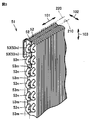
- FIG. 3 is a perspective view partially showing a water heat exchanger provided in the air conditioner in FIG.
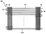
- FIG. 4 is a front view showing the water heat exchanger in FIG. 3.
- the water heat exchanger 51 in the present embodiment is a fin-and-tube heat exchanger, and has a plurality of fins 52 and multi-row pipes 53.
- the fin 52 has a flat plate shape.
- the fin 52 has a thin plate shape.
- the fins 52 are formed from a plate material excellent in thermal conductivity, for example, an aluminum plate.
- a plurality of fins 52 are arranged side by side in one direction indicated by an arrow 101 in FIG.
- the plurality of fins 52 are arranged at an interval from each other.
- the plurality of fins 52 are arranged at equal intervals.
- the fin 52 has a rectangular flat plate shape. When viewed from the arrangement direction indicated by arrow 101, fin 52 has a long side in the direction indicated by arrow 103 orthogonal to the direction indicated by arrow 101, and is orthogonal to the direction indicated by arrow 101 and the direction indicated by arrow 103. It has a rectangular shape having a short side in the direction indicated by the arrow 102 (the depth direction of the water heat exchanger 51).
- the multi-row pipe 53 is formed from a pipe member having excellent thermal conductivity.
- the multi-row piping 53 extends through the plurality of fins 52.
- the multi-row piping 53 is routed so as to extend in the virtual plane 210 and the virtual plane 220.
- the virtual plane 210 and the virtual plane 220 are arranged at a distance from each other in the depth direction of the water heat exchanger 51 indicated by the arrow 102.
- the multi-row pipes 53 are provided in two rows in the depth direction of the water heat exchanger 51.
- the multi-row pipe 53 includes a refrigerant pipe 53m to which a refrigerant flowing through the refrigeration circuit 21 is supplied and a water pipe 53n to which water flowing through the hot water supply circuit 31 is supplied. Both ends of the refrigerant pipe 53m are connected to a pipe constituting the refrigerant branch path 21q of the refrigeration circuit 21, and both ends of the water pipe 53n are connected to a pipe constituting the hot water supply circuit 31.
- the refrigerant pipe 53m and the water pipe 53n are provided as pipes independent of each other.
- the refrigerant pipe 53m is routed in the virtual plane 210, and the water pipe 53n is routed in the virtual plane 220.
- the refrigerant pipe 53m includes a section 56 that extends in one direction while passing through the plurality of fins 52, a section 57 that is inverted in a U-shape, and a plurality of fins 52 in the virtual plane 210.
- a section 58 extending in the opposite direction while penetrating is arranged to repeat.
- the water pipe 53n is routed in the virtual plane 220 in the same form as the refrigerant pipe 53m.
- each fin 52 is formed from a single plate in the direction in which the virtual plane 210 and the virtual plane 220 are arranged.
- the fin 52 is not formed with a slit for separating the first row of the refrigerant pipes 53m and the second row of the water pipes 53n in the depth direction of the water heat exchanger 51.
- FIG. 5 is a perspective view showing a modification of the water heat exchanger shown in FIG.
- refrigerant pipe 53m is routed in virtual plane 210 and virtual plane 220
- water pipe 53n is routed in virtual plane 210 and virtual plane 220.
- the refrigerant pipes 53m and the water pipes 53n are alternately arranged.
- the structure of the multi-row piping 53 in the water heat exchanger 51 described above is an example, and the number of the multi-row piping 53 in the depth direction of the water heat exchanger 51 and the routing of the piping in each virtual plane. Etc. are appropriately changed.
- the fins 52 are provided in a form connected between the rows.
- the structure of the water heat exchanger 51 according to the first embodiment of the present invention described above will be described together.
- the water heat exchanger 51 as the fin-and-tube heat exchanger according to the present embodiment includes a refrigerant and a cover. Water is heated by exchanging heat with water as a heating fluid.
- the water heat exchanger 51 has a flat plate shape, a plurality of fins 52 arranged at intervals, and a plurality of fins 52 extending through the plurality of fins 52, orthogonal to the fins 52, and arranged in parallel to each other.
- the multi-row piping 53 arranged in the virtual planes 210 and 220.
- the multi-row pipe 53 includes a water pipe 53n as a fluid pipe through which water flows and a refrigerant pipe 53m as a refrigerant pipe through which a refrigerant flows.
- Each fin 52 is formed from a single plate in the direction in which the virtual planes 210 and 220 are arranged.
- the air conditioner 10 is a water heat exchanger 51 as a fin-and-tube heat exchanger, a refrigeration circuit 21 constituting a heat pump cycle, and a fluid circuit through which water as a fluid to be heated flows.
- the hot water supply circuit 31 is provided.
- the refrigerant is supplied from the refrigeration circuit 21 to the refrigerant pipe 53m as the refrigerant pipe, and the water is supplied from the hot water supply circuit 31 to the water pipe 53n as the fluid pipe.
- the fin and hood that is conventionally mounted on the air conditioner is used for the production of the water heat exchanger 51.
- Tube-type heat exchanger production equipment can be used. Thereby, it becomes easy to produce the water heat exchanger 51, and manufacturing cost can be reduced. As a result, the air conditioner 10 having a hot water supply function can be widely spread.
- the refrigerant pipe extending from the compressor is connected or welded to the water heat exchanger in the hot water storage tank at the site where the hot water storage tank is installed. Work is required.
- the water heat exchanger 51 is integrated in the outdoor unit 12, it can implement to refrigerant
- FIG. 6 is a block diagram showing a configuration of the air conditioner in FIG.
- the air conditioner 10 includes a control unit 61 for controlling driving of various devices mounted on the air conditioner 10.
- the controller 61 opens the flow path switching valve 28, closes the flow path switching valve 29, and drives the fan 26. .
- the refrigerant discharged from the compressor 22 is guided to the outdoor heat exchanger 23, and heat is exchanged between the refrigerant and the outdoor air supplied by driving the fan 26 in the outdoor heat exchanger 23.
- the control unit 61 closes the flow path switching valve 28, opens the flow path switching valve 29, and drives the fan 26. Stop. Thereby, the refrigerant discharged from the compressor 22 is guided to the water heat exchanger 51, and heat exchange is performed between the refrigerant and the water flowing through the hot water supply circuit 31 in the water heat exchanger 51.
- FIG. 7 is a circuit diagram showing a configuration relating to control of the air conditioner in FIG.
- control unit 61 is mounted inside indoor unit 14 and controls compressor 22 and fan 26 of outdoor unit 12.
- a flow switch 33 detection unit that detects the flow of water is arranged in the outdoor unit 12. That is, the flow switch 33 (detection unit) is disposed in a portion provided outside the hot water supply circuit 31 (fluid circuit).
- the control unit 61 is realized as a control board, for example.
- the control unit 61 includes switches 62a and 62b, a signal generation circuit 63, and a terminal unit 64 provided with terminals T1 to T5.
- the terminal portion 64 can be realized by a connector, for example.
- the terminal T1 as the first terminal is a terminal for supplying power from the power source 65 to the fan 26 of the outdoor unit 12 (showing the motor of the fan 26 in FIG. 7).
- a terminal T2 as a second terminal is a terminal for receiving a signal from the flow switch 33. The signal input to the terminal T2 is sent to the signal generation circuit 63.
- a terminal T3 as a third terminal is a terminal for supplying power from the power source 65 to the compressor 22 of the outdoor unit 12.
- a terminal T4 as a fourth terminal is a neutral terminal of the power supply 65.
- a terminal T5 as a fifth terminal is a ground terminal of the power supply 65.
- the switch 62a as the first switch is connected between the power supply 65 and the terminal T1, and is turned on / off according to a signal from the signal generation circuit 63.
- the switch 62b as the second switch is connected between the power supply 65 and the terminal T3, and is turned on / off in accordance with a signal from the signal generation circuit 63.
- the outdoor unit 12 includes a terminal plate 67 including terminals T11 to T15.
- Terminals T11 and T13 are power supply terminals.
- the terminal T12 is a signal terminal.
- Terminal T14 is a neutral terminal.
- Terminal T15 is a ground terminal.
- the terminal T11 is electrically connected to the fan 26 (fan motor) and is also electrically connected to the terminal T1 of the control unit 61 through the wiring L1 as the first wiring.
- the terminal T12 is electrically connected to the flow switch 33, and is also electrically connected to the terminal T2 of the control unit 61 through the wiring L2 as the second wiring.
- the terminal T13 is electrically connected to the compressor 22, and is also electrically connected to the terminal T3 of the control unit 61 through the wiring L3 as the third wiring.
- the terminal T14 is connected to the terminal T12 via the flow switch 33, and is electrically connected to the terminal T4 of the control unit 61 through the wiring L4 as the fourth wiring.
- the terminal T15 is electrically connected to the terminal T5 of the control unit 61 through the wiring L5 as the fifth wiring.
- the fan 26 is provided with an overtemperature protection circuit 67a. Further, an overload protection circuit 67b is provided between the terminal T13 and the compressor 22.
- the signal generation circuit 63 In the case of indoor air conditioning or hot water supply, the signal generation circuit 63 generates a signal for turning on the switch 62b and sends the signal to the switch 62b. When the switch 62b is turned on, power from the power source 65 is supplied to the compressor 22 and the compressor 22 operates.
- the flow switch 33 When water is flowing in the hot water supply circuit 31 (see FIG. 1), the flow switch 33 is turned on. On the other hand, when water is not flowing in the hot water supply circuit 31 (see FIG. 1), the flow switch 33 is turned off.
- the potential of the terminal T12 changes according to the on / off state of the flow switch 33. This change in potential is input to the terminal T2 of the control unit 61 through the wiring L2 as a signal indicating the detection result by the flow switch 33.
- the signal generation circuit 63 receives a signal from the flow switch 33 through the terminal T2. This signal indicates a detection result by the flow switch 33.
- the signal generation circuit 63 When the detection result by the flow switch 33 indicates the flow of water in the hot water supply circuit 31, the signal generation circuit 63 generates a signal for turning off the switch 62a and sends the signal to the switch 62a. The fan 26 stops when the switch 62a is turned off.
- the control unit 61 When the detection result by the flow switch 33 does not indicate the flow of water in the hot water supply circuit 31, the control unit 61 generates a signal for turning on the switch 62a and sends the signal to the switch 62a. When the switch 62a is turned on, power from the power source 65 is supplied to the fan 26, and the fan 26 operates.
- the control unit 61 mounted on the indoor unit 14 controls the compressor 22 and the fan 26 accommodated in the outdoor unit 12. Moreover, the flow switch 33 which is a detection part is arrange
- the outdoor unit 12 does not require a control board.
- the outdoor unit can be controlled by a simple control circuit.
- FIG. 8 is a diagram showing a circuit configuration of an air conditioner with a hot water supply function according to Embodiment 3 of the present invention.
- the air conditioner in the present embodiment basically has the same structure as that of the air conditioner 10 in the first embodiment. Hereinafter, the description of the overlapping structure will not be repeated.
- refrigerant circuit 21q in FIG. 1 is not provided in refrigeration circuit 21, and refrigeration circuit 21 is configured as a simple circulation path.
- refrigeration circuit 21 instead of the outdoor heat exchanger 23 and the water heat exchanger 51 in FIG. 1, an integrated heat exchanger 71 is provided, and further, the flow path switching valve 28 and the refrigeration circuit 21 are provided.
- the flow path switching valve 29 is not provided.
- the integrated heat exchanger 71 is provided on the path of the refrigeration circuit 21.
- the integrated heat exchanger 71 is a fin-and-tube heat exchanger described in the first embodiment with reference to FIGS. 3 to 5. That is, in the integrated heat exchanger 71, the refrigerant pipe 53m and the water pipe 53n are routed as the multi-row pipe 53.
- the integrated heat exchanger 71 functions as an outdoor heat exchanger for exchanging heat between the refrigerant and outdoor air and a water heat exchanger for exchanging heat between the refrigerant and water.
- the heat exchanger also has the structure of the water heat exchanger 51 shown in FIG.
- the fan 26 is provided so as to face the integrated heat exchanger 71.
- the fan 26 is driven. Thereby, in the integrated heat exchanger 71, heat is exchanged between the refrigerant and the outdoor air supplied by driving the fan 26. On the other hand, when the flow of water in the hot water supply circuit 31 is detected by the flow switch 33, the drive of the fan 26 is stopped. Thereby, in the integrated heat exchanger 71, heat is exchanged between the refrigerant and the water flowing through the hot water supply circuit 31.
- the outdoor unit 12 is configured in a compact manner, and the air conditioner The manufacturing cost can be further reduced.
- Embodiment 3 of the present invention configured as described above can achieve the same effects as those described in Embodiment 1.
- FIG. 9 is a diagram showing a circuit configuration of an air conditioner with a hot water supply function according to Embodiment 4 of the present invention.
- FIG. 10 is a circuit diagram showing a configuration relating to control of the air conditioner in FIG.
- the air conditioner in the present embodiment has basically the same structure as that of the air conditioner in the third embodiment. Hereinafter, the description of the overlapping structure will not be repeated.
- the refrigeration circuit 21 is further provided with a pressure (pressure) switch 81.
- the pressure switch 81 On the path of the refrigeration circuit 21, the pressure switch 81 is disposed between the compressor 22 and the integrated heat exchanger 71.
- the pressure switch 81 is connected to a connection pipe near the discharge port of the compressor 22 by brazing (welding).
- the pressure switch 81 detects the pressure of the refrigerant flowing through the refrigeration circuit 21 at the discharge position of the compressor 22.
- the pressure switch 81 is connected in series with the flow switch 33 between the terminal T12 and the terminal T14.
- an automatic return type is used in which the opening / closing of the contact is automatically returned when the detected pressure is restored to a certain value.
- the pressure switch 81 even when the flow of water in the hot water supply circuit 31 is detected by the flow switch 33, if the pressure of the refrigerant is detected by the pressure switch 81 to be equal to or higher than a predetermined value, the pressure is detected. The contact of the switch 81 is opened, and the fan 26 is driven. At this time, in the integrated heat exchanger 71, the refrigerant exchanges heat with outdoor air supplied by driving the fan 26 in addition to the water flowing through the hot water supply circuit 31. Thereby, while the temperature of the refrigerant
- This invention is mainly applied to an air conditioner with a hot water supply function.
Landscapes
- Engineering & Computer Science (AREA)
- General Engineering & Computer Science (AREA)
- Mechanical Engineering (AREA)
- Physics & Mathematics (AREA)
- Thermal Sciences (AREA)
- Chemical & Material Sciences (AREA)
- Combustion & Propulsion (AREA)
- Geometry (AREA)
- Heat-Pump Type And Storage Water Heaters (AREA)
- Air Conditioning Control Device (AREA)
- Details Of Fluid Heaters (AREA)
- Other Air-Conditioning Systems (AREA)
- Details Of Heat-Exchange And Heat-Transfer (AREA)
- Heat-Exchange Devices With Radiators And Conduit Assemblies (AREA)
Abstract
Description
図1は、この発明の実施の形態1における給湯機能付きの空気調和機の回路構成を示す図である。図2は、図1中の空気調和機の室外機を示す斜視図である。
本実施の形態では、実施の形態1における空気調和機10に適用可能な給湯時のファン制御の一例について説明する。図6は、図1中の空気調和機の構成を示すブロック図である。
図8は、この発明の実施の形態3における給湯機能付きの空気調和機の回路構成を示す図である。本実施の形態における空気調和機は、実施の形態1における空気調和機10と比較して、基本的には同様の構造を備える。以下、重複する構造についてはその説明を繰り返さない。
図9は、この発明の実施の形態4における給湯機能付きの空気調和機の回路構成を示す図である。図10は、図9中の空気調和機の制御に関する構成を示した回路図である。本実施の形態における空気調和機は、実施の形態3における空気調和機と比較して、基本的には同様の構造を備える。以下、重複する構造についてはその説明を繰り返さない。
Claims (6)
- 冷媒と被加熱流体との間で熱交換を行なうことによって被加熱流体を加熱する、フィンアンドチューブ型熱交換器であって、
平板形状を有し、互いに間隔を隔てて配列される複数枚のフィンと、
複数枚の前記フィンを貫きながら延伸し、前記フィンに直交し、互いに平行に並ぶ複数の仮想平面内に配索される多列配管とを備え、
前記多列配管は、被加熱流体が流れる流体用配管と、冷媒が流れる冷媒用配管とを含み、
各前記フィンは、前記仮想平面の並び方向において一体物の板材から形成される、フィンアンドチューブ型熱交換器。 - 複数の前記仮想平面として、第1平面と、前記第1平面と間隔を隔てて並ぶ第2平面とが設けられ、
前記流体用配管および前記冷媒用配管は、それぞれ、前記第1平面および前記第2平面内に配索される、請求項1に記載のフィンアンドチューブ型熱交換器。 - 被加熱流体を加熱する機能を有する空気調和機であって、
請求項1または2に記載のフィンアンドチューブ型熱交換器と、
ヒートポンプサイクルを構成する冷凍回路と、
被加熱流体が流れる流体回路とを備え、
前記冷凍回路から前記冷媒用配管に冷媒が供給され、前記流体回路から前記流体用配管に被加熱流体が供給される、空気調和機。 - 前記冷凍回路の経路上に設けられ、前記フィンアンドチューブ型熱交換器とともに室外に設置される室外側熱交換器と、
前記室外側熱交換器に室外空気を供給するためのファンと、
前記流体回路における被加熱流体の流れを検知する検知部と、
前記検知部において被加熱流体の流れが検知された場合に前記ファンを停止させ、被加熱流体の流れが検知されなかった場合に前記ファンを駆動させる制御部とを備える、請求項3に記載の空気調和機。 - 前記冷凍回路の経路上に設けられ、前記フィンアンドチューブ型熱交換器とともに室外に設置される室外側熱交換器をさらに備え、
前記フィンアンドチューブ型熱交換器と前記室外側熱交換器とが一体に設けられる、請求項3または4に記載の空気調和機。 - 前記フィンアンドチューブ型熱交換器と前記室外側熱交換器とが一体に設けられ、
前記冷凍回路の経路上に設けられ、前記室外側熱交換器に供給する冷媒を圧縮する圧縮機と、
前記冷凍回路の経路上に設けられ、冷媒の圧力を検知するプレッシャースイッチとをさらに備え、
前記制御部は、前記検知部において被加熱流体の流れが検知された場合であって、前記プレッシャースイッチにおいて冷媒の圧力が予め定められた値以上であると検知された場合に、前記ファンを駆動させる、請求項4に記載の空気調和機。
Priority Applications (2)
| Application Number | Priority Date | Filing Date | Title |
|---|---|---|---|
| CN201390000861.9U CN204963302U (zh) | 2012-12-11 | 2013-11-29 | 空气调节机 |
| SG11201501687VA SG11201501687VA (en) | 2012-12-11 | 2013-11-29 | Fin-and-tube type heat exchanger and air conditioner |
Applications Claiming Priority (4)
| Application Number | Priority Date | Filing Date | Title |
|---|---|---|---|
| JP2012-270275 | 2012-12-11 | ||
| JP2012270275 | 2012-12-11 | ||
| JP2013215285A JP6030039B2 (ja) | 2012-12-11 | 2013-10-16 | 空気調和機 |
| JP2013-215285 | 2013-10-16 |
Publications (1)
| Publication Number | Publication Date |
|---|---|
| WO2014091948A1 true WO2014091948A1 (ja) | 2014-06-19 |
Family
ID=50934240
Family Applications (1)
| Application Number | Title | Priority Date | Filing Date |
|---|---|---|---|
| PCT/JP2013/082218 Ceased WO2014091948A1 (ja) | 2012-12-11 | 2013-11-29 | フィンアンドチューブ型熱交換器および空気調和機 |
Country Status (4)
| Country | Link |
|---|---|
| JP (1) | JP6030039B2 (ja) |
| CN (1) | CN204963302U (ja) |
| SG (1) | SG11201501687VA (ja) |
| WO (1) | WO2014091948A1 (ja) |
Cited By (1)
| Publication number | Priority date | Publication date | Assignee | Title |
|---|---|---|---|---|
| EP3557149A4 (en) * | 2016-12-16 | 2019-12-25 | Mitsubishi Electric Corporation | OUTDOOR UNIT FOR AIR CONDITIONING |
Citations (8)
| Publication number | Priority date | Publication date | Assignee | Title |
|---|---|---|---|---|
| JPS6218813B2 (ja) * | 1982-07-14 | 1987-04-24 | Misawa Homes Co | |
| JPH0218453Y2 (ja) * | 1982-08-19 | 1990-05-23 | ||
| JPH055577A (ja) * | 1991-06-27 | 1993-01-14 | Sanden Corp | ヒ−トポンプ式冷暖房給湯システム |
| JP2002048483A (ja) * | 2000-08-01 | 2002-02-15 | Corona Corp | 熱交換器 |
| JP2004020085A (ja) * | 2002-06-18 | 2004-01-22 | Matsushita Electric Ind Co Ltd | 給湯・空調装置 |
| JP2010223537A (ja) * | 2009-03-25 | 2010-10-07 | Toshiba Carrier Corp | ヒートポンプ給湯システム |
| JP2010223492A (ja) * | 2009-03-23 | 2010-10-07 | Toshiba Carrier Corp | 水熱交換器、ヒートポンプ式給湯装置 |
| JP2010255994A (ja) * | 2009-04-28 | 2010-11-11 | Hitachi Appliances Inc | 給湯機能付ヒートポンプ式空気調和機 |
-
2013
- 2013-10-16 JP JP2013215285A patent/JP6030039B2/ja not_active Expired - Fee Related
- 2013-11-29 WO PCT/JP2013/082218 patent/WO2014091948A1/ja not_active Ceased
- 2013-11-29 SG SG11201501687VA patent/SG11201501687VA/en unknown
- 2013-11-29 CN CN201390000861.9U patent/CN204963302U/zh not_active Expired - Fee Related
Patent Citations (8)
| Publication number | Priority date | Publication date | Assignee | Title |
|---|---|---|---|---|
| JPS6218813B2 (ja) * | 1982-07-14 | 1987-04-24 | Misawa Homes Co | |
| JPH0218453Y2 (ja) * | 1982-08-19 | 1990-05-23 | ||
| JPH055577A (ja) * | 1991-06-27 | 1993-01-14 | Sanden Corp | ヒ−トポンプ式冷暖房給湯システム |
| JP2002048483A (ja) * | 2000-08-01 | 2002-02-15 | Corona Corp | 熱交換器 |
| JP2004020085A (ja) * | 2002-06-18 | 2004-01-22 | Matsushita Electric Ind Co Ltd | 給湯・空調装置 |
| JP2010223492A (ja) * | 2009-03-23 | 2010-10-07 | Toshiba Carrier Corp | 水熱交換器、ヒートポンプ式給湯装置 |
| JP2010223537A (ja) * | 2009-03-25 | 2010-10-07 | Toshiba Carrier Corp | ヒートポンプ給湯システム |
| JP2010255994A (ja) * | 2009-04-28 | 2010-11-11 | Hitachi Appliances Inc | 給湯機能付ヒートポンプ式空気調和機 |
Cited By (1)
| Publication number | Priority date | Publication date | Assignee | Title |
|---|---|---|---|---|
| EP3557149A4 (en) * | 2016-12-16 | 2019-12-25 | Mitsubishi Electric Corporation | OUTDOOR UNIT FOR AIR CONDITIONING |
Also Published As
| Publication number | Publication date |
|---|---|
| JP6030039B2 (ja) | 2016-11-24 |
| SG11201501687VA (en) | 2015-04-29 |
| JP2014134373A (ja) | 2014-07-24 |
| CN204963302U (zh) | 2016-01-13 |
Similar Documents
| Publication | Publication Date | Title |
|---|---|---|
| JP5172012B2 (ja) | 空気調和装置 | |
| JP6644154B2 (ja) | 空気調和装置 | |
| US20150040841A1 (en) | System and method for improving a water heating cycle in a multi-purpose hvac system | |
| CN105008823A (zh) | 热泵热水器 | |
| CN102762934A (zh) | 三流体热交换器以及使用了该三流体热交换器的空气调节供热水系统 | |
| EP2872836A1 (en) | Energy efficient air heating, air conditioning and water heating system | |
| US20180023818A1 (en) | Heat pump system | |
| CN103415749B (zh) | 二元制冷循环装置 | |
| CN204630138U (zh) | 空调器 | |
| CN102661640B (zh) | 三通热力膨胀阀 | |
| CN211575619U (zh) | 空调系统 | |
| CN203869367U (zh) | 一种地暖、热水器、空调三合一机组 | |
| US9488384B2 (en) | Heat pump water module with condensing coil in water storage tank | |
| JP6016603B2 (ja) | 空気調和機および加熱ユニット | |
| JP6030039B2 (ja) | 空気調和機 | |
| KR20120081815A (ko) | 공기 조화기 | |
| KR100849613B1 (ko) | 온수 급탕 및 바닥 난방이 가능한 고효율 히트 펌프식냉난방 장치 | |
| TWI529356B (zh) | 冷熱共生熱泵設備 | |
| CN104697245A (zh) | 耦合热泵系统 | |
| CN108007010B (zh) | 一种热泵系统 | |
| CN206019070U (zh) | 换热器、空调室外机、热泵系统及空调器 | |
| CN104457070B (zh) | 具有多重热互换增焓的热泵系统 | |
| JP6248393B2 (ja) | 温調システム | |
| JP5747838B2 (ja) | 暖房給湯システム | |
| CN223204532U (zh) | 一种热泵热水器 |
Legal Events
| Date | Code | Title | Description |
|---|---|---|---|
| WWE | Wipo information: entry into national phase |
Ref document number: 201390000861.9 Country of ref document: CN |
|
| 121 | Ep: the epo has been informed by wipo that ep was designated in this application |
Ref document number: 13863454 Country of ref document: EP Kind code of ref document: A1 |
|
| NENP | Non-entry into the national phase |
Ref country code: DE |
|
| WWE | Wipo information: entry into national phase |
Ref document number: IDP00201504319 Country of ref document: ID |
|
| 122 | Ep: pct application non-entry in european phase |
Ref document number: 13863454 Country of ref document: EP Kind code of ref document: A1 |