WO2014091706A1 - 撮像装置 - Google Patents
撮像装置 Download PDFInfo
- Publication number
- WO2014091706A1 WO2014091706A1 PCT/JP2013/007030 JP2013007030W WO2014091706A1 WO 2014091706 A1 WO2014091706 A1 WO 2014091706A1 JP 2013007030 W JP2013007030 W JP 2013007030W WO 2014091706 A1 WO2014091706 A1 WO 2014091706A1
- Authority
- WO
- WIPO (PCT)
- Prior art keywords
- image
- color
- image sensor
- image data
- filter
- Prior art date
- Legal status (The legal status is an assumption and is not a legal conclusion. Google has not performed a legal analysis and makes no representation as to the accuracy of the status listed.)
- Ceased
Links
Images




Classifications
-
- G—PHYSICS
- G06—COMPUTING OR CALCULATING; COUNTING
- G06T—IMAGE DATA PROCESSING OR GENERATION, IN GENERAL
- G06T3/00—Geometric image transformations in the plane of the image
- G06T3/40—Scaling of whole images or parts thereof, e.g. expanding or contracting
- G06T3/4038—Image mosaicing, e.g. composing plane images from plane sub-images
-
- H—ELECTRICITY
- H04—ELECTRIC COMMUNICATION TECHNIQUE
- H04N—PICTORIAL COMMUNICATION, e.g. TELEVISION
- H04N23/00—Cameras or camera modules comprising electronic image sensors; Control thereof
- H04N23/10—Cameras or camera modules comprising electronic image sensors; Control thereof for generating image signals from different wavelengths
- H04N23/12—Cameras or camera modules comprising electronic image sensors; Control thereof for generating image signals from different wavelengths with one sensor only
-
- H—ELECTRICITY
- H04—ELECTRIC COMMUNICATION TECHNIQUE
- H04N—PICTORIAL COMMUNICATION, e.g. TELEVISION
- H04N23/00—Cameras or camera modules comprising electronic image sensors; Control thereof
- H04N23/90—Arrangement of cameras or camera modules, e.g. multiple cameras in TV studios or sports stadiums
-
- H—ELECTRICITY
- H04—ELECTRIC COMMUNICATION TECHNIQUE
- H04N—PICTORIAL COMMUNICATION, e.g. TELEVISION
- H04N25/00—Circuitry of solid-state image sensors [SSIS]; Control thereof
- H04N25/10—Circuitry of solid-state image sensors [SSIS]; Control thereof for transforming different wavelengths into image signals
- H04N25/11—Arrangement of colour filter arrays [CFA]; Filter mosaics
- H04N25/13—Arrangement of colour filter arrays [CFA]; Filter mosaics characterised by the spectral characteristics of the filter elements
- H04N25/133—Arrangement of colour filter arrays [CFA]; Filter mosaics characterised by the spectral characteristics of the filter elements including elements passing panchromatic light, e.g. filters passing white light
-
- H—ELECTRICITY
- H04—ELECTRIC COMMUNICATION TECHNIQUE
- H04N—PICTORIAL COMMUNICATION, e.g. TELEVISION
- H04N25/00—Circuitry of solid-state image sensors [SSIS]; Control thereof
- H04N25/10—Circuitry of solid-state image sensors [SSIS]; Control thereof for transforming different wavelengths into image signals
- H04N25/11—Arrangement of colour filter arrays [CFA]; Filter mosaics
- H04N25/13—Arrangement of colour filter arrays [CFA]; Filter mosaics characterised by the spectral characteristics of the filter elements
- H04N25/134—Arrangement of colour filter arrays [CFA]; Filter mosaics characterised by the spectral characteristics of the filter elements based on three different wavelength filter elements
-
- H—ELECTRICITY
- H04—ELECTRIC COMMUNICATION TECHNIQUE
- H04N—PICTORIAL COMMUNICATION, e.g. TELEVISION
- H04N25/00—Circuitry of solid-state image sensors [SSIS]; Control thereof
- H04N25/10—Circuitry of solid-state image sensors [SSIS]; Control thereof for transforming different wavelengths into image signals
- H04N25/11—Arrangement of colour filter arrays [CFA]; Filter mosaics
- H04N25/13—Arrangement of colour filter arrays [CFA]; Filter mosaics characterised by the spectral characteristics of the filter elements
- H04N25/135—Arrangement of colour filter arrays [CFA]; Filter mosaics characterised by the spectral characteristics of the filter elements based on four or more different wavelength filter elements
- H04N25/136—Arrangement of colour filter arrays [CFA]; Filter mosaics characterised by the spectral characteristics of the filter elements based on four or more different wavelength filter elements using complementary colours
-
- H—ELECTRICITY
- H04—ELECTRIC COMMUNICATION TECHNIQUE
- H04N—PICTORIAL COMMUNICATION, e.g. TELEVISION
- H04N23/00—Cameras or camera modules comprising electronic image sensors; Control thereof
- H04N23/80—Camera processing pipelines; Components thereof
- H04N23/84—Camera processing pipelines; Components thereof for processing colour signals
- H04N23/843—Demosaicing, e.g. interpolating colour pixel values
Definitions
- the present invention relates to an imaging device including an imaging element array in which a plurality of imaging elements are arranged.
- a mobile device such as a mobile phone or a smartphone is equipped with a camera module as a standard.
- a camera module as a standard.
- thinning portable devices there is a strong demand for thinning portable devices, and accordingly, thinning of camera modules is also required.
- Patent Document 1 discloses an imaging device that includes a camera array in which a plurality of imaging elements are arranged and a plurality of lens elements corresponding to the imaging elements, and each imaging element is configured by a monochromatic filter. Yes.
- this imaging apparatus small image data is acquired from each imaging element, and the plurality of image data are combined to generate a single piece of high-definition image data.
- Patent Document 2 discloses an image input device in which a single color filter is arranged in each unit composed of a plurality of light receiving cells. Similarly to Patent Document 1, in Patent Document 2, since a single color filter is arranged in each unit, the lens is reduced in size.
- Patent Documents 1 and 2 since only one color signal can be obtained from each image sensor, when a color image is to be obtained, an image captured by an image sensor in which at least three different color filters are arranged. It is necessary to synthesize data. When combining a plurality of pieces of image data obtained from the image sensor into a single piece of image data, it is necessary to use a combining process such as aligning and adding the plurality of pieces of image data, or a super-resolution process.
- JP 2011-523538 A Japanese Patent No. 3705766
- An object of the present invention is to provide an imaging apparatus capable of generating a color image at high speed in an imaging apparatus including an imaging element array in which a plurality of imaging elements are arranged.
- An imaging apparatus includes a plurality of optical systems arranged in a matrix and an imaging element array including imaging elements corresponding to the optical systems, and the imaging element array has at least different spectral characteristics. It includes a first image sensor on which two types of color filters are arranged, and a second image sensor on which one type of color filter is arranged.
- a color moving image can be generated at high speed in an imaging apparatus including an imaging element array in which a plurality of imaging elements are arranged.
- FIG. 1 shows the outline
- FIG. 1 It is the figure which showed the 6th example of the arrangement pattern of the color filter of the imaging device by embodiment of this invention. It is a block diagram of an imaging device at the time of adopting the arrangement pattern of FIG. It is a block diagram of an imaging device at the time of adopting the arrangement pattern of FIG.
- FIG. 1 is a diagram showing an outline of an imaging apparatus according to an embodiment of the present invention.
- the imaging device includes an imaging element array 11 for imaging a subject and an array lens 12 provided on the light receiving surface side of the imaging element array 11.
- the array lens 12 includes a plurality of lenses 20 (an example of an optical system) arranged in a matrix.
- the image sensor array 11 includes a plurality of image sensors 30 corresponding to the respective lenses 20.
- a plurality of image sensors 30 are arranged in a matrix with, for example, M (M is an integer of 2 or more) rows ⁇ N (N is an integer of 2 or more) columns.
- lenses 20 are provided corresponding to the respective imaging elements 30.
- the lens 20 a single lens may be employed, or a lens group in which a plurality of lenses are combined may be employed.
- the imaging element 30 includes, for example, a plurality of pixels arranged in m (an integer of 2 or more) rows ⁇ n (an integer of 2 or more) columns.
- a CMOS image sensor or a CCD image sensor is employed as the image sensor 30.
- the image sensor 30 may be configured by dividing one image sensor formed on the same substrate into a plurality of light receiving regions, or by forming a plurality of image sensors on the same substrate. Alternatively, it may be configured by arranging image pickup devices on different substrates on the same plane. Further, the angle of view of the array lens 12 is adjusted so that substantially the same subject can be imaged. Therefore, the image data captured by each image sensor 30 is image data in which substantially the same subject is reflected.
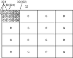
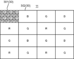
- FIG. 2 is a diagram showing a first example of the arrangement pattern of the color filters of the imaging apparatus according to the embodiment of the present invention.
- an RGB mosaic filter is arranged on the image sensor 30 in the first row and the first column, and R (red), G (green), or B ( A single color filter (blue) is placed.
- the image sensor 30 on which the RGB mosaic filter is arranged is described as an image sensor 301
- the image sensor 30 on which the monochromatic filter is arranged is described as an image sensor 302.
- the R, G, B monochromatic filters arranged in the image sensor 302 are arranged in a Bayer array.
- the RGB mosaic filters arranged in the image sensor 301 are arranged in a Bayer array with R, G, and B color filters.
- a Bayer arrangement a mode is adopted in which G color filters are arranged in a checkered pattern, and R and B color filters are arranged in a one-to-one ratio in the remaining region, but this is only an example. Absent.
- the color filters arranged in a checkered pattern may adopt a B or R Bayer arrangement.
- RGB mosaic filters, B, G, and B single color filters are arranged in order from the first column in the first row, and R, G in order from the first column in the second row.
- R, and G single color filters are arranged, and in the third row, G, B, G, and B single color filters are arranged in order from the first column, and the fourth row is the first column. In this order, R, G, R, and G single color filters are arranged.
- the image pickup element 301 is divided into, for example, 4 rows ⁇ 6 columns of photoelectric conversion regions (pixels) 303, and R, G, or B monochromatic filters are arranged in the respective photoelectric conversion regions 303.
- the imaging element 301 has a plurality of pixels arranged in a matrix of predetermined rows m ⁇ predetermined columns n.
- One pixel is arranged in the photoelectric conversion region 303.
- the image sensor 301 has a plurality of pixels arranged in 4 rows ⁇ 6 columns, but this is only an example.
- a plurality of pixels may be arranged so that the number of pixels of the image sensor 301 is about 1 Mbyte.
- the RGB mosaic filter is arranged in one image sensor 301 in the image sensor array 11 shown in FIG. 2, for example, when capturing a moving image, only image data captured by the image sensor 301 is used. By doing so, a color image can be obtained without performing a process of combining a plurality of image data. On the other hand, when a still image is captured, a high-definition color image can be obtained by combining a plurality of image data captured by all the image sensors 30.
- the image sensor 301 corresponds to an example of a first image sensor in which at least two types of color filters having different spectral characteristics are arranged.
- the image sensor 302 corresponds to an example of a second image sensor on which a single color filter is arranged.
- the RGB mosaic filter is disposed only on one image sensor 30, but this is only an example, and may be disposed on two or more image sensors 30, for example, two or three. .
- the RGB mosaic filter is arranged in the image sensor 30 in the first row and the first column, but this is an example, and the RGB mosaic filter may be arranged at other positions such as near the center.
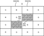
- FIG. 3 is a diagram showing a second example of the color filter arrangement pattern of the imaging apparatus according to the embodiment of the present invention.
- RGB mosaic filters are arranged in the two image sensors 301 in the second row and third column and the third row and second column, and any of R, G, or B is arranged in the remaining image sensor 302. These single color filters are arranged.
- the other points are the same as the arrangement pattern shown in FIG.
- the RGB mosaic filter is provided at the center of the image sensor array 11. Therefore, when a moving image is picked up, a color image can be obtained by combining image data picked up by the two image pickup elements 301, and a color image with a high S / N ratio can be obtained even in a dark scene. Therefore, the arrangement pattern of FIG. 3 is effective in a dark scene.
- FIG. 4 is a diagram showing a third example of the arrangement pattern of the color filters of the imaging apparatus according to the embodiment of the present invention.
- an RG mosaic filter is arranged in the image sensor 301 in the second row and third column
- a BG mosaic filter is arranged in the image sensor 301 in the third row and second column.
- the other points are the same as the arrangement pattern shown in FIG.
- the R color filter and the G color filter are arranged in a checkered pattern.
- R and G color filters are alternately arranged in order from the first column in the first row, and G and R in the second row in order from the first column.
- R and G color filters are arranged such that the color filters are arranged alternately.
- the B color filter and the G color filter are arranged in a checkered pattern. Specifically, in the image sensor 301 in the third row and the second column, B and G color filters are alternately arranged in order from the first column in the first row, and G and B in the second row in order from the first column. B and G color filters are arranged such that the color filters are arranged alternately.
- the lens 20 can be downsized. Further, when the thickness of the lens 20 is the same as that when the three-color mosaic filter is employed, the performance of the lens 20 can be improved.
- the B information is not obtained from the image sensor 301 in the second row and the third column
- the R information is not obtained from the image sensor 301 in the third row and the second column.
- information about R, G, and B is obtained, so that an RGB color image is obtained. Therefore, in the arrangement pattern of FIG. 4, when capturing a moving image, the image data obtained by the image sensor 301 in the second row and the third column is synthesized with the image data obtained by the image sensor 301 in the third row and the second column. Thus, a color image can be obtained.
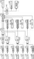
- FIG. 5 is a block diagram of the imaging apparatus when the arrangement pattern of FIG. 2 is adopted.
- the imaging apparatus includes a lens 20, an imaging element RGB, imaging elements G1 to Gk (k is an integer of 2 or more), imaging elements B1 to Bk, imaging elements R1 to Rk, a color separation unit 501, a switch 502, an image processing unit 503, A display 504, a compression unit 505, a recording medium 506, a communication unit 507, memories G10, B10, R10, super-resolution processing units G30, B30, R30, and memories G20, B20, R20 are included.
- the lens 20 is provided corresponding to each of the imaging elements RGB, the imaging elements G1 to Gk, the imaging elements B1 to Bk, and the imaging elements R1 to Rk.
- the image sensor RGB corresponds to the image sensor 301 in FIG.
- the image sensors G1 to Gk correspond to the image sensor 302 on which the G color filter of FIG. 2 is arranged.
- the image sensors B1 to Bk correspond to the image sensor 302 in which the color filter B in FIG. 2 is arranged.
- the image sensors R1 to Rk correspond to the image sensor 302 in which the R color filter of FIG. 2 is arranged.
- the color separation unit 501 separates image data captured by the image sensor RGB into three color components R, G, and B.
- the switch 502 connects the color separation unit 501 to the image processing unit 503 when a moving image is captured. As a result, the R, G, and B color components separated by the color separation unit 501 are output to the image processing unit 503.
- the switch 502 connects the color separation unit 501 to the memories G10, B10, and R10 when a still image is captured. As a result, the R, G, and B color components separated by the color separation unit 501 are written in the memories G10, B10, and R10, respectively.
- the image processing unit 503 When a moving image is captured, the image processing unit 503 performs predetermined image processing on the image data of the R, G, and B color components separated by the color separation unit 501 to generate a color image, and displays the display 504. Output to. In addition, when a still image is captured, the image processing unit 503 reads the image data subjected to the super-resolution processing from each of the memories G20, B20, and R20, performs gamma correction, generates a color image, and displays it on the display 504. Output.
- examples of the predetermined image processing include color interpolation processing and gamma correction.
- the color interpolation process for example, a process of interpolating missing pixels in image data of R, G, and B color components that have been color-separated is employed.
- the gamma correction for example, a process of correcting the image characteristic of the image data obtained by the image sensor 30 to a characteristic suitable for the output characteristic of the display 504 is employed.
- the image processing unit 503 also outputs the image data after the image processing to the compression unit 505 as necessary.
- the memory G10 is an image memory that individually holds the image data of the G color component of the image data obtained by the image sensor RGB and the k pieces of image data obtained by the image sensors G1 to Gk.
- the memory B10 is an image memory that individually holds the image data of the B color component of the image data obtained by the image sensor RGB and the k pieces of image data obtained by the image sensors B1 to Bk.
- the memory R10 is an image memory that individually holds R color component image data of image data obtained by the image sensor RGB and k pieces of image data obtained by the image sensors R1 to Rk.
- the super-resolution processing unit G30 performs super-resolution processing on the image data held in the memory G10, generates a single G-component super-resolution processing image, and writes it to the memory G20.
- the super-resolution processing units B30 and R30 also generate one B-component and R-component super-resolution processing image from the image data held in the memories B10 and R10, respectively. Write to B20, R20.
- the super-resolution processing units G30, B30, and R30 depend on the lens performance with respect to the resolution of the image sensor 30, for example, an image having a resolution of a sub-pixel level about 5 times the resolution of the image sensor 30. Generate data.
- the super-resolution processing units G30, B30, and R30 to generate image data at the sub-pixel level, it is preferable that the shift between the image data captured by the adjacent image sensors 30 is at the sub-pixel level.
- super-resolution processing units G30, B30, and R30 are provided, but instead, a G addition unit that combines the image data held in the memories G10, B10, and R10 into one piece of image data, B An addition unit and an R addition unit may be provided.
- the G addition unit, the B addition unit, and the R addition unit each store a deviation amount of each image sensor 30 when a certain image sensor 30 is used as a reference. Then, the G addition unit, the B addition unit, and the R addition unit each align the image data captured by each imaging element 30 using this shift amount, and then add them to one image data. What is necessary is just to synthesize.
- the memory G20 stores G image data that has undergone super-resolution processing. Similarly to the memory G20, the memories B20 and R20 also store B and R image data subjected to super-resolution processing, respectively.
- the compression unit 505 compresses the image data output from the image processing unit 503.
- the compression method of the compression unit 505 various methods can be employed.
- the compression unit 505 in the case of a moving image, the compression unit 505 is an The image data may be compressed by a method such as H.264 or motion JPEG.
- the compression unit 505 may compress image data using a method such as JPEG.
- the display 504 employs various display devices such as a liquid crystal panel and an organic EL panel, for example, and displays the image data output from the image processing unit 503.
- the recording medium 506 is configured by, for example, a stationary rewritable storage device such as a hard disk or a portable rewritable storage device such as a memory card, and stores the image data compressed by the compression unit 505.
- the communication unit 507 includes, for example, a wireless LAN or wired LAN communication module or a mobile phone communication module, and transmits the image data compressed by the compression unit 505 to the outside and receives the image data from the outside.
- a subject is imaged by the image sensor RGB, and image data is imaged.
- the captured image data is separated into R, G, and B color component image data by the color separation unit 501 and input to the image processing unit 503 via the switch 502.
- the image data input to the image processing unit 503 is subjected to gamma correction and color interpolation processing, converted into image data composed of three color components R, G, and B, and displayed on the display 504.
- the image data is compressed by the compression unit 505 and then stored in the recording medium 506.
- the image data is transmitted to the outside by the communication unit 507 when a transmission instruction is input by the user, for example.
- the subject is imaged by all the imaging elements 30, and image data is acquired.
- the G image data picked up by the image pickup devices RGB and the G image data picked up by the image pickup devices G1 to Gk are temporarily stored in the memory G10.
- the B image data captured by the image sensor RGB and the B image data captured by the image sensors B1 to Bk are also temporarily stored in the memory B10, and the R image data captured by the image sensor RGB.
- the R image data picked up by the image pickup devices R1 to Rk is also temporarily stored in the memory R10.
- the super-resolution processing unit G30 combines the G image data stored in the memory G10 into one G image data by super-resolution processing, and writes it into the memory G20.
- the super-resolution processing units B30 and R30 also combine the B and R image data stored in the memories B10 and R10 into a single piece of B and R image data, and write them into the memories B20 and R20.
- the G, B, and R image data after super-resolution processing stored in the memories G20, B20, and R20 are subjected to image processing such as gamma correction and color interpolation processing by the image processing unit 503, and the display 504 is processed. Is displayed. Further, the R, G, B image data after the super-resolution processing is stored in the recording medium 506 as needed after image processing in the image processing unit, or is transmitted to the outside by the communication unit 507.
- the present invention when still images are captured, the image data captured by all the image sensors 30 are combined.
- the present invention is not limited to this, and the image data captured by the image sensors RGB is still captured. May be adopted.
- high-quality image data is not required, so there is no problem even if image data captured by the image sensor RGB is employed as a still image.
- an imaging unit may be provided with an operation unit, and a user may operate the operation unit to select a moving image mode or a still image mode.
- FIG. 9 is a block diagram of the imaging apparatus when the arrangement pattern of FIG. 3 is adopted.
- two image sensors RGB1 and RGB2 are provided, two color separation units 501 and 508 are provided corresponding to the image sensors RGB1 and RGB2, respectively.
- a combining unit 509 is provided for combining image data picked up by the image pickup devices RGB1 and RGB2.
- the image sensor RGB1 corresponds to, for example, the image sensor 301 in the second row and the third column in FIG. 3
- the image sensor RGB2 corresponds to, for example, the image sensor 301 in the third row and the second column in FIG.
- the description of the same configuration as in FIG. 5 is omitted.
- the switch 502 connects the color separation unit 501 and the color separation unit 508 to the synthesis unit 509 when a moving image is captured.
- the switch 502 connects the color separation unit 501 and the color separation unit 508 to the memories G10, B10, and R10 when a still image is captured.
- the color separation unit 501 separates image data captured by the image sensor RGB1 into three color components R, G, and B. Similar to the color separation unit 501, the color separation unit 508 also separates the image data captured by the image sensor RGB2 into R, G, and B color components.
- the memory G10 includes two G color component image data color-separated by the color separation unit 501 and the color separation unit 508, and k G color component image data imaged by the imaging elements G1 to Gk. Hold.
- the memories B10 and R10 also hold image data of B and R color components, respectively.
- the composition unit 509 When a moving image is captured, the composition unit 509 performs image data of R, G, and B color components that are color-separated by the color separation unit 501 and R, G, and B colors that are color-separated by the color separation unit 508.
- the component image data is combined with one piece of image data.
- the synthesizing unit 509 stores in advance the amount of deviation between the image sensor RGB1 and the image sensor RGB2. Then, the color separation unit 508 aligns the image data color-separated by the color separation unit 501 and the image data color-separated by the color separation unit 508 using this shift amount, and adds each color component, One image data composed of R, G, and B color components is generated.
- the composition unit 509 since the composition unit 509 only needs to perform alignment and addition processing, the image data can be synthesized with a low load.
- the combining unit 509 may combine the image data captured by the image sensor RGB1 and the image data captured by the image sensor RGB2 using super-resolution processing. Note that when super-resolution processing is adopted, the processing load becomes larger than when alignment and addition processing is performed. However, if the number of images of the image pickup devices RGB1 and RGB2 is small, the load is low, so there is a certain limitation. Under the above conditions (for example, when the frame rate is small), there is no problem even if the synthesizing unit 509 adopts super-resolution processing.
- FIG. 10 is a block diagram of the imaging apparatus when the arrangement pattern of FIG. 4 is adopted.
- two image sensors RG and BG are provided, two color separation units 501 and 508 are provided corresponding to the image sensors RG and BG, respectively.
- a synthesizing unit 509 for synthesizing image data captured by the image sensors RG and BG is provided. 10, the description of the same configuration as in FIG. 9 is omitted.
- the synthesis unit 509 when capturing a moving image, the synthesis unit 509 generates G color component image data from two image data captured by the two imaging elements 30 of the imaging element RG and the imaging element BG.
- the B color component image data is generated from the image data captured by the image sensor BG
- the R color component image data is generated from the image data captured by the image sensor RG.
- the synthesizing unit 509 may add only the image data of the G color component.
- the combining unit 509 may combine the image data of the two G color components using super-resolution processing.
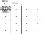
- FIG. 6 is a diagram showing a fourth example of the color filter arrangement pattern of the imaging apparatus according to the embodiment of the present invention.
- the YMGC mosaic filter is arranged in the image sensor 301 in the first row and the first column, and any one of R, G, or B single color filter is arranged in the remaining image sensor 302. Is arranged.
- the other points are the same as the arrangement pattern shown in FIG.
- YMCG mosaic filter color filters having spectral characteristics of Y (yellow), M (magenta), C (cyan), and G (green) are arranged.
- the Y, M, C, and G color filters are arranged in 4 rows ⁇ 6 columns, but this is merely an example, and other patterns and the number of pixels may be arranged.
- the block diagram of the imaging apparatus may be the one shown in FIG. Specifically, in FIG. 5, the image sensor RGB is replaced with the image sensor 301 in which the YMCG mosaic filter shown in FIG. 6 is arranged.
- the image sensor 301 on which the YMCG mosaic filter is arranged is described as an image sensor YMCG.
- the color separation unit 501 separates the image data captured by the image sensor YMCG into four color components Y, M, C, and G.
- the image processing unit 503 converts the four color components Y, M, C, and G separated by the color separation unit 501 into three color components R, G, and B through arithmetic processing. Further, image processing such as gradation conversion is performed and displayed on the display 504.
- the process of converting the four color components Y, M, C, and G into the three color components R, G, and B may be performed by the color separation unit 501.
- the color separation unit 501 separates image data captured by the image sensor YMCG into four color components Y, M, C, and G, and then performs R, G, Converted into B color components and written in the memories G10, B10, and R10, respectively.
- FIG. 7 is a diagram showing a fifth example of the arrangement pattern of the color filters of the imaging apparatus according to the embodiment of the present invention.
- a WRGB mosaic filter is arranged in the image sensor 301 in the first row and the first column, and any one of R, G, or B monochrome filters is arranged in the remaining image sensor 302. Is arranged.
- the other points are the same as the arrangement pattern shown in FIG.
- the WRGB mosaic filter is a filter in which a W (white) region where no color filter is arranged and a color filter having spectral characteristics of B (blue), R (red), and G (green) are arranged in a mosaic pattern. It is.
- a W color filter is arranged in the W region, but in reality, no W color filter is arranged in the W region.
- the W, R, G, and B color filters are arranged in 4 rows ⁇ 6 columns, but this is only an example, and other arrangement patterns may be arranged.
- the block diagram of the imaging apparatus may be the one shown in FIG. Specifically, in FIG. 5, the image sensor RGB is replaced with an image sensor 301 in which the WRGB mosaic filter shown in FIG. 7 is arranged.
- the image sensor 301 in which the WRGB mosaic filter is arranged is described as an image sensor WRGB.
- the color separation unit 501 separates image data captured by the image sensor WRGB into four color components W, R, G, and B.
- the image processing unit 503 calculates the three color components R, G, and B by performing arithmetic processing on the four color components W, R, G, and B color-separated by the color separation unit 501.
- image processing such as gradation conversion may be performed and displayed on the display 504.
- the color separation unit 501 may perform the process of converting the four color components W, R, G, and B into the three color components R, G, and B.
- the color separation unit 501 separates image data captured by the image sensor WRGB into four color components W, R, G, and B, and then colors G, B, and R What is necessary is just to convert into a component and to write in memory G10, B10, and R10, respectively.
- FIG. 8 is a diagram showing a sixth example of the arrangement pattern of the color filters of the imaging apparatus according to the embodiment of the present invention.
- the WYR mosaic filter is arranged in the image sensor 301 in the first row and the first column, and any one of R, G, or B monochrome filters is arranged in the remaining image sensor 302. Is arranged.
- the other points are the same as the arrangement pattern shown in FIG.
- the WYR mosaic filter In the WYR mosaic filter, a W (white) region in which no color filter is arranged and a region in which color filters having spectral characteristics of Y (yellow) and R (red) are arranged in a mosaic pattern. .
- the W color filters are arranged in a checkered pattern, and the R color filters and the Y color filters are arranged in a one-to-one ratio in the remaining region, but this is only an example.
- the color filter arranged in a checkered pattern may be an R or Y color filter.
- the W, Y, and R color filters are arranged in 4 rows ⁇ 6 columns, but this is only an example and may be arranged in other patterns.
- the block diagram of the imaging apparatus may be the one shown in FIG. Specifically, in FIG. 5, the image sensor RGB is replaced with the image sensor 301 in which the WYR mosaic filter shown in FIG. 8 is arranged.
- the image sensor 301 on which the WYR mosaic filter is arranged is described as an image sensor WYR.
- the color separation unit 501 separates image data picked up by the image pickup element WYR into three color components W, Y, and R.
- the image processing unit 503 converts the W, Y, and R color components color-separated by the color separation unit 501 into R, G, and B color components by an arithmetic process.
- Image processing such as tone conversion may be performed and displayed on the display 504.
- the process of converting the W, Y, and R color components into the R, G, and B color components may be performed by the color separation unit 501.
- the color separation unit 501 separates the image data captured by the image sensor WYR into three color components W, Y, and R, and then performs G, B, and R by arithmetic processing. What is necessary is just to convert into a color component and to write in memory G10, B10, and R10, respectively.
- the image sensor 301 is arranged in the first row and the first column. However, this is only an example, and it may be arranged in another position. A plurality of image sensors 301 may be arranged. When a plurality of image sensors 301 are arranged, the block diagram of the image sensor shown in FIG. 9 may be employed.
- the imaging apparatus of the present embodiment when capturing a moving image, the image data captured by the imaging element 301 in which at least two colors of mosaic filters are arranged is employed.
- the load can be suppressed and the power consumption can be suppressed.
- the number of the image pickup elements 301 is one or two. However, the number is not limited to this and may be three or more.
- the imaging device includes a plurality of optical systems arranged in a matrix and an imaging element array including imaging elements corresponding to each optical system, and the imaging element array has spectral characteristics. It includes a first image sensor on which at least two different color filters are arranged, and a second image sensor on which one kind of color filter is arranged.
- an image sensor array is configured by arranging a plurality of image sensors in a matrix.
- the imaging element array includes a first imaging element in which two types of color filters are arranged and a second imaging element in which one type of color filter is arranged. Therefore, when capturing a moving image that requires high-speed processing, it is possible to generate a color image by combining image data captured by the first image sensor.
- the processing load is reduced as compared with a case where a color image is synthesized from image data captured by all the image sensors. It can be obtained at high speed. In addition, power saving is achieved by reducing the processing load.
- a color image can be generated at a higher speed.
- the image data captured by the first image sensor and the second image sensor are combined to have three color components. Color image data can also be generated at high speed.
- high-definition color images can be obtained by combining image data captured by all image sensors using super-resolution processing or the like. it can.
- a mosaic filter of at least two colors is arranged in the first image sensor, and a monochromatic filter is arranged in the second image sensor.
- a color image having at least two color components can be obtained in real time.
- a monochromatic filter is disposed in the second image sensor, a high-definition color image can be obtained by combining image data obtained by the first image sensor and the second image sensor.
- the single color filter arranged in at least one of the second imaging elements has the same color as any one color constituting the mosaic filter.
- the single color filter arranged in the second image sensor is the same color as any one of the mosaic filters arranged in the first image sensor, it is obtained by the first image sensor and the second image sensor. By synthesizing the obtained image data, higher-definition image data can be obtained for the color.
- the first image sensor is used for obtaining moving image data.
- the first image sensor is used when obtaining moving image data. Therefore, it is possible to obtain a moving color image at a higher speed than in the case where moving image data is generated by combining image data captured by all the imaging elements.
- an RGB mosaic filter is disposed in the first image sensor.
- the RGB mosaic filter is arranged in the first image sensor, a color moving image having RGB color components can be generated in real time.
- first imaging elements There are a plurality of the first imaging elements, and at least one of the first imaging elements is provided with a GR mosaic filter, and the remaining first imaging elements are provided with a GB mosaic filter. preferable.
- the wavelength band transmitted through the optical system is narrower than that in the case where the three color filters are arranged, and the first imaging element.
- the optical system disposed in the element can be reduced in size.
- the GR mosaic filter is disposed in at least one first image sensor and the GB mosaic filter is disposed in the remaining first image sensor, image data captured by both the first image sensors is stored. By synthesizing, a color moving image having RGB color components can be generated in real time.
- a YMCG mosaic filter is disposed in the first image sensor.
- the YMCG mosaic filter which is generally more sensitive than the RGB mosaic filter, is arranged in the first image sensor, it becomes more sensitive and obtains image data with good S / N in real time. be able to.
- a WRGB mosaic filter is disposed in the first image sensor.
- image data of W (white) color components in addition to RGB can be obtained.
- the W color component has spectral sensitivity in the entire band. Therefore, by generating image data of RGB color components using image data of W color components, it is possible to obtain image data with higher sensitivity and good S / N.
- a WYR mosaic filter is disposed in the first image sensor.
Landscapes
- Engineering & Computer Science (AREA)
- Multimedia (AREA)
- Signal Processing (AREA)
- Physics & Mathematics (AREA)
- Spectroscopy & Molecular Physics (AREA)
- General Physics & Mathematics (AREA)
- Theoretical Computer Science (AREA)
- Color Television Image Signal Generators (AREA)
- Processing Of Color Television Signals (AREA)
- Studio Devices (AREA)
Abstract
Description
配置され、4行目には、1列目から順に、R、G、R、Gの単色の色フィルタが配置されている。
(1)本実施の形態による撮像装置は、マトリックス状に配置された複数の光学系と、各光学系に対応した撮像素子を備える撮像素子アレイとを含み、前記撮像素子アレイは、分光特性の異なる少なくとも2種類の色フィルタが配置された第1撮像素子と、1種類の色フィルタが配置された第2撮像素子とを含む。
Claims (10)
- マトリックス状に配置された複数の光学系と、
各光学系に対応した撮像素子を備える撮像素子アレイとを含み、
前記撮像素子アレイは、
分光特性の異なる少なくとも2種類の色フィルタが配置された第1撮像素子と、
1種類の色フィルタが配置された第2撮像素子とを含む撮像装置。 - 前記第1撮像素子は、少なくとも2色のモザイクフィルタが配置され、
前記第2撮像素子は、単色フィルタが配置されている請求項1記載の撮像装置。 - 少なくとも1つの前記第2撮像素子に配置された単色フィルタは、前記モザイクフィルタを構成するいずれか1つの色と同色である請求項2記載の撮像装置。
- 前記第1撮像素子は、動画の画像データを得るために使用される請求項1~3のいずれかに記載の撮像装置。
- 前記第1撮像素子は、RGBモザイクフィルタが配置されている請求項1~4のいずれかに記載の撮像装置。
- 前記第1撮像素子は、複数存在し、
少なくとも1つの前記第1撮像素子は、GRモザイクフィルタが配置され、
残りの前記第1撮像素子は、GBモザイクフィルタが配置されている請求項1~4のいずれかに記載の撮像装置。 - 前記第1撮像素子は、YMCGモザイクフィルタが配置されている請求項1~4のいずれかに記載の撮像装置。
- 前記第1撮像素子は、WRGBモザイクフィルタが配置されている請求項1~4のいずれかに記載の撮像装置。
- 前記第1撮像素子は、WYRモザイクフィルタが配置されている請求項1~4のいずれかに記載の撮像装置。
- 前記第2撮像素子は、R、G、又はBの単色フィルタが配置されている請求項1~9のいずれかに記載の撮像装置。
Priority Applications (2)
| Application Number | Priority Date | Filing Date | Title |
|---|---|---|---|
| US14/651,363 US20150332433A1 (en) | 2012-12-14 | 2013-11-29 | Imaging device |
| JP2014551871A JPWO2014091706A1 (ja) | 2012-12-14 | 2013-11-29 | 撮像装置 |
Applications Claiming Priority (2)
| Application Number | Priority Date | Filing Date | Title |
|---|---|---|---|
| JP2012273378 | 2012-12-14 | ||
| JP2012-273378 | 2012-12-14 |
Publications (1)
| Publication Number | Publication Date |
|---|---|
| WO2014091706A1 true WO2014091706A1 (ja) | 2014-06-19 |
Family
ID=50934014
Family Applications (1)
| Application Number | Title | Priority Date | Filing Date |
|---|---|---|---|
| PCT/JP2013/007030 Ceased WO2014091706A1 (ja) | 2012-12-14 | 2013-11-29 | 撮像装置 |
Country Status (3)
| Country | Link |
|---|---|
| US (1) | US20150332433A1 (ja) |
| JP (1) | JPWO2014091706A1 (ja) |
| WO (1) | WO2014091706A1 (ja) |
Cited By (1)
| Publication number | Priority date | Publication date | Assignee | Title |
|---|---|---|---|---|
| WO2019026600A1 (ja) * | 2017-07-31 | 2019-02-07 | ソニーセミコンダクタソリューションズ株式会社 | カメラモジュールおよび撮像装置 |
Families Citing this family (2)
| Publication number | Priority date | Publication date | Assignee | Title |
|---|---|---|---|---|
| KR101725044B1 (ko) * | 2010-05-27 | 2017-04-11 | 삼성전자주식회사 | 촬영이 가능한 디스플레이 장치 |
| CN108377325A (zh) * | 2018-05-21 | 2018-08-07 | Oppo广东移动通信有限公司 | 拍摄装置、电子设备及图像获取方法 |
Citations (3)
| Publication number | Priority date | Publication date | Assignee | Title |
|---|---|---|---|---|
| JP2001523929A (ja) * | 1997-11-14 | 2001-11-27 | タンゲン、レイダル、イー. | 光電子カメラおよびそれで画像をフォーマッティングする方法 |
| JP2005176117A (ja) * | 2003-12-12 | 2005-06-30 | Canon Inc | 撮像装置 |
| JP2007520166A (ja) * | 2004-01-26 | 2007-07-19 | ディジタル・オプティックス・コーポレイション | サブピクセル解像度を有する薄型カメラ |
Family Cites Families (15)
| Publication number | Priority date | Publication date | Assignee | Title |
|---|---|---|---|---|
| US6211521B1 (en) * | 1998-03-13 | 2001-04-03 | Intel Corporation | Infrared pixel sensor and infrared signal correction |
| US6657663B2 (en) * | 1998-05-06 | 2003-12-02 | Intel Corporation | Pre-subtracting architecture for enabling multiple spectrum image sensing |
| US7746396B2 (en) * | 2003-12-17 | 2010-06-29 | Nokia Corporation | Imaging device and method of creating image file |
| DE102005013044B4 (de) * | 2005-03-18 | 2007-08-09 | Siemens Ag | Fluoreszenz-Scanner |
| WO2007086155A1 (ja) * | 2006-01-24 | 2007-08-02 | Matsushita Electric Industrial Co., Ltd. | 固体撮像装置、信号処理方法及びカメラ |
| JP5106870B2 (ja) * | 2006-06-14 | 2012-12-26 | 株式会社東芝 | 固体撮像素子 |
| JP4846608B2 (ja) * | 2007-01-26 | 2011-12-28 | 株式会社東芝 | 固体撮像装置 |
| KR101475464B1 (ko) * | 2008-05-09 | 2014-12-22 | 삼성전자 주식회사 | 적층형 이미지 센서 |
| JP2010252277A (ja) * | 2009-04-20 | 2010-11-04 | Panasonic Corp | 固体撮像装置及び電子カメラ |
| US10091439B2 (en) * | 2009-06-03 | 2018-10-02 | Flir Systems, Inc. | Imager with array of multiple infrared imaging modules |
| CN103081457B (zh) * | 2010-08-24 | 2016-04-13 | 富士胶片株式会社 | 固态成像装置 |
| JP5649990B2 (ja) * | 2010-12-09 | 2015-01-07 | シャープ株式会社 | カラーフィルタ、固体撮像素子、液晶表示装置および電子情報機器 |
| KR101262507B1 (ko) * | 2011-04-11 | 2013-05-08 | 엘지이노텍 주식회사 | 픽셀, 픽셀 어레이, 픽셀 어레이의 제조방법 및 픽셀 어레이를 포함하는 이미지센서 |
| JP5864990B2 (ja) * | 2011-10-03 | 2016-02-17 | キヤノン株式会社 | 固体撮像装置およびカメラ |
| TW201523117A (zh) * | 2013-12-09 | 2015-06-16 | Himax Tech Ltd | 相機陣列系統 |
-
2013
- 2013-11-29 JP JP2014551871A patent/JPWO2014091706A1/ja not_active Withdrawn
- 2013-11-29 WO PCT/JP2013/007030 patent/WO2014091706A1/ja not_active Ceased
- 2013-11-29 US US14/651,363 patent/US20150332433A1/en not_active Abandoned
Patent Citations (3)
| Publication number | Priority date | Publication date | Assignee | Title |
|---|---|---|---|---|
| JP2001523929A (ja) * | 1997-11-14 | 2001-11-27 | タンゲン、レイダル、イー. | 光電子カメラおよびそれで画像をフォーマッティングする方法 |
| JP2005176117A (ja) * | 2003-12-12 | 2005-06-30 | Canon Inc | 撮像装置 |
| JP2007520166A (ja) * | 2004-01-26 | 2007-07-19 | ディジタル・オプティックス・コーポレイション | サブピクセル解像度を有する薄型カメラ |
Cited By (1)
| Publication number | Priority date | Publication date | Assignee | Title |
|---|---|---|---|---|
| WO2019026600A1 (ja) * | 2017-07-31 | 2019-02-07 | ソニーセミコンダクタソリューションズ株式会社 | カメラモジュールおよび撮像装置 |
Also Published As
| Publication number | Publication date |
|---|---|
| US20150332433A1 (en) | 2015-11-19 |
| JPWO2014091706A1 (ja) | 2017-01-05 |
Similar Documents
| Publication | Publication Date | Title |
|---|---|---|
| TWI386049B (zh) | A solid-state imaging device, and a device using the solid-state imaging device | |
| US20130153748A1 (en) | Solid-state image sensor and electronic apparatus | |
| JP5853166B2 (ja) | 画像処理装置及び画像処理方法並びにデジタルカメラ | |
| US9210387B2 (en) | Color imaging element and imaging device | |
| US20120044394A1 (en) | Digital camera | |
| US20100328485A1 (en) | Imaging device, imaging module, electronic still camera, and electronic movie camera | |
| US8111298B2 (en) | Imaging circuit and image pickup device | |
| JP2013026672A (ja) | 固体撮像装置及びカメラモジュール | |
| CN104412581B (zh) | 彩色摄像元件及摄像装置 | |
| US9219894B2 (en) | Color imaging element and imaging device | |
| JP4253634B2 (ja) | デジタルカメラ | |
| US9185375B2 (en) | Color imaging element and imaging device | |
| US9143747B2 (en) | Color imaging element and imaging device | |
| US7663679B2 (en) | Imaging apparatus using interpolation and color signal(s) to synthesize luminance | |
| US20070159542A1 (en) | Color filter array with neutral elements and color image formation | |
| US20150109493A1 (en) | Color imaging element and imaging device | |
| CN103416067A (zh) | 摄像装置及摄像程序 | |
| WO2014091706A1 (ja) | 撮像装置 | |
| WO2023098282A1 (zh) | 图像传感器、摄像模组、电子设备、图像生成方法和装置 | |
| WO2020059050A1 (ja) | 撮像素子、撮像装置、撮像方法およびプログラム | |
| JP2010268354A (ja) | イメージセンサ及びそのイメージセンサを備える撮像装置 | |
| JP2015088810A (ja) | 色差信号を利用した画像処理方法 | |
| JPH02214286A (ja) | カラー固体撮像素子及びカラー撮像装置 |
Legal Events
| Date | Code | Title | Description |
|---|---|---|---|
| 121 | Ep: the epo has been informed by wipo that ep was designated in this application |
Ref document number: 13863574 Country of ref document: EP Kind code of ref document: A1 |
|
| ENP | Entry into the national phase |
Ref document number: 2014551871 Country of ref document: JP Kind code of ref document: A |
|
| WWE | Wipo information: entry into national phase |
Ref document number: 14651363 Country of ref document: US |
|
| NENP | Non-entry into the national phase |
Ref country code: DE |
|
| 122 | Ep: pct application non-entry in european phase |
Ref document number: 13863574 Country of ref document: EP Kind code of ref document: A1 |