WO2014091664A1 - 容器内への飲料の層状分配方法及びそのための冶具 - Google Patents
容器内への飲料の層状分配方法及びそのための冶具 Download PDFInfo
- Publication number
- WO2014091664A1 WO2014091664A1 PCT/JP2013/006462 JP2013006462W WO2014091664A1 WO 2014091664 A1 WO2014091664 A1 WO 2014091664A1 JP 2013006462 W JP2013006462 W JP 2013006462W WO 2014091664 A1 WO2014091664 A1 WO 2014091664A1
- Authority
- WO
- WIPO (PCT)
- Prior art keywords
- mmaq
- beverage
- container
- jig
- pores
- Prior art date
- Legal status (The legal status is an assumption and is not a legal conclusion. Google has not performed a legal analysis and makes no representation as to the accuracy of the status listed.)
- Ceased
Links
Images


Classifications
-
- A—HUMAN NECESSITIES
- A47—FURNITURE; DOMESTIC ARTICLES OR APPLIANCES; COFFEE MILLS; SPICE MILLS; SUCTION CLEANERS IN GENERAL
- A47J—KITCHEN EQUIPMENT; COFFEE MILLS; SPICE MILLS; APPARATUS FOR MAKING BEVERAGES
- A47J31/00—Apparatus for making beverages
- A47J31/44—Parts or details or accessories of beverage-making apparatus
- A47J31/46—Dispensing spouts, pumps, drain valves or like liquid transporting devices
- A47J31/462—Dispensing spouts, pumps, drain valves or like liquid transporting devices with an intermediate liquid storage tank
-
- B—PERFORMING OPERATIONS; TRANSPORTING
- B67—OPENING, CLOSING OR CLEANING BOTTLES, JARS OR SIMILAR CONTAINERS; LIQUID HANDLING
- B67D—DISPENSING, DELIVERING OR TRANSFERRING LIQUIDS, NOT OTHERWISE PROVIDED FOR
- B67D1/00—Apparatus or devices for dispensing beverages on draught
- B67D1/08—Details
- B67D1/12—Flow or pressure control devices or systems, e.g. valves, gas pressure control, level control in storage containers
-
- B—PERFORMING OPERATIONS; TRANSPORTING
- B67—OPENING, CLOSING OR CLEANING BOTTLES, JARS OR SIMILAR CONTAINERS; LIQUID HANDLING
- B67D—DISPENSING, DELIVERING OR TRANSFERRING LIQUIDS, NOT OTHERWISE PROVIDED FOR
- B67D1/00—Apparatus or devices for dispensing beverages on draught
- B67D1/08—Details
- B67D1/12—Flow or pressure control devices or systems, e.g. valves, gas pressure control, level control in storage containers
- B67D1/127—Froth control
-
- B—PERFORMING OPERATIONS; TRANSPORTING
- B67—OPENING, CLOSING OR CLEANING BOTTLES, JARS OR SIMILAR CONTAINERS; LIQUID HANDLING
- B67D—DISPENSING, DELIVERING OR TRANSFERRING LIQUIDS, NOT OTHERWISE PROVIDED FOR
- B67D1/00—Apparatus or devices for dispensing beverages on draught
- B67D1/08—Details
- B67D1/12—Flow or pressure control devices or systems, e.g. valves, gas pressure control, level control in storage containers
- B67D1/1277—Flow control valves
Definitions
- the present invention relates to a method of distributing a beverage in a container in a layered manner when the beverage is distributed and served in a container such as a drinking container at the time of drinking or in a restaurant, etc., and the layer structure of the beverage in the container
- the present invention relates to a jig for performing distribution.
- a cocktail has been known as a method of providing a beverage characterized by visual beauty in a drinking container.
- a cocktail distributed in a multilayer shape is known.
- such multi-layered cocktails are collectively referred to as “Poos Cafe Style” and are more widely known.
- Cocktails are provided in this way in a multi-layered shape, characterized by visual beauty and accepted by consumers, but beverages distributed in such a multi-layered shape are A plurality of types of beverages having different colors and specific gravity are stacked in a layer for each beverage using the specific gravity difference.
- a beverage having the highest specific gravity is normally poured into a glass to form a first layer (lowermost layer).
- the next heavy drink is gently poured into the glass so as not to be mixed with the first drink to form the second drink.
- the same pouring process as the second layer is repeated until all the prepared types of beverage are used.
- the tip of a drink stirring bar called Madler or an elongated spoon called Bar Spoon (Patent Document 1) is brought into contact with the inner wall surface of the glass.
- a small amount was poured into the inner wall of the glass through a mudler or bar spoon.
- this method using a mudler or a bar spoon requires a considerable degree of technical skill and has problems in terms of simplicity, etc., and any other method used for dispensing the multi-layer cocktail can be used. It could not be applied to beverages.
- Patent Document 2 discloses a method of dispensing a beverage having two or more liquid layers into a container using a concentrated liquid such as coffee or milk.
- the method includes providing at least one source of a first concentrate and at least one source of a second concentrate, diluted from the first concentrate source and into a drinking container.
- a second liquid diluted to a concentration lower than the concentration of the liquid layer is supplied above the supplied beverage to form a layered liquid layer.
- the dilution rate in the upper liquid is made higher than that in the lower liquid, and the liquid is gently supplied into the container.
- this method is limited to the provision of a specific beverage, such as when using a concentrated liquid, and the first liquid layer and the second liquid layer are distributed.
- the flow rate of the second liquid is adjusted and the liquid is gently fed, but when applied to beverages other than the above, It is difficult to provide a beverage in a beverage container that is distributed in layers, and therefore the method of this disclosure is only applicable to limited beverages.
- a jig for producing a two-layer beer more easily has been devised in beer and the like whose specific gravity approximates and is provided to consumers together with the beer.
- Such a conventional jig (hereinafter referred to as “conventional jig”) has a support for placing the jig in the opening of the container, and a partial spherical shape (a very shallow bowl for pouring beverage from above). It consists of a part that looks like a face down.
- An object of the present invention is to provide a method for distributing beverages in a layered manner into a container when the beverage is distributed and served in a container such as a drinking container at the time of drinking or at a restaurant, etc., and the layer structure distribution of the beverage into the container In particular, it can be applied to the distribution of beverages having a relatively similar specific gravity, and anyone who does not need technical skill can easily and reliably form a beverage having a layered structure. It is an object to provide a method for dispensing into a container and a jig for performing such dispensing.
- the present inventors can be applied to the distribution of beverages having a relatively similar specific gravity as in the case of beer.
- various types of jigs were prototyped and verified, and as a result, the jig bottom composed of the outer peripheral wall and the porous porous plate A porous perforated plate is used on the upper surface of the first beverage previously injected into the container, using a jig comprising a jig container part and a support part for placing the jig container part on the upper part of the container.
- the present invention supplies a plurality of types of beverages in a layered manner in a container, and in the method for distributing beverages in a container in which a layer structure is formed, on the upper surface of the first beverage previously injected into the container.
- the second beverage is supplied in a layered form while suppressing turbulent flow and stirring by a continuous droplet or fine flow through a porous porous plate. It consists of a distribution method.
- the second beverage is supplied through a porous porous plate as a method of supplying the second beverage in a layered manner while suppressing turbulent flow and stirring by continuous droplets or fine flow. It can be suitably performed by adjusting the second beverage to be droplets before reaching the liquid level in the container.
- adjusting the second beverage supplied through the porous porous plate to be a droplet before reaching the liquid level in the container is to adjust the size of the pores of the porous porous plate, It can be performed by adjusting the water head pressure of the second beverage in the pores of the pore porous plate.
- the method of supplying the second beverage in a layered manner while suppressing turbulent flow and stirring with continuous droplets or fine flow is the bottom of the container having an outer peripheral wall. It can carry out using the jig which used as the pore porous plate.
- beverages to which the beverage distribution method of the present invention can be applied include beer, sparkling liquor, beer-like beverages, other miscellaneous liquors, liqueurs, and soft drinks.
- the present invention provides a plurality of types of beverages comprising a jig container part composed of an outer peripheral wall and a jig bottom made of a porous porous plate, and a support part for placing the jig container part on top of the container.
- the invention includes an invention of a jig for supplying a beverage in a layered manner in a container and distributing the beverage having a layer structure in the container.
- the plurality of pores of the porous porous plate at the bottom of the jig container portion of the jig for performing the distribution of the beverage having the layer structure in the container supply the second beverage in layers while suppressing turbulent flow and stirring.
- positioned circularly along the outer peripheral edge part of a circular jig bottom part can be mentioned as a especially preferable structure.
- the jig container part is a container fitting groove for stably placing the jig on the upper part of the container on the support part for placing on the upper part of the container It can be set as the structure which formed.
- the jig container part has a structure in which a separation groove for preventing a droplet or a fine flow of the second beverage from being transmitted to the support part is provided in the support part for placing on the upper part of the container. be able to.
- the support part for mounting the jig container part on the upper part of the container can include a grip part for gripping the jig and placing or removing the jig on the container upper part.
- the present invention specifically relates to (1) a method of supplying a plurality of types of beverages in a layered manner in a container, and injecting the beverage first into the container in the method of distributing the beverage in a layer structure.
- a layer structure characterized in that the second beverage is supplied in a layered form on the upper surface of the first beverage through a porous porous plate while suppressing turbulent flow and stirring by continuous droplets or fine flow.
- the distribution of the beverage having the layer structure according to the above (1), wherein the second beverage to be supplied is adjusted so as to be a droplet before reaching the liquid level in the container The method and (3) the second beverage supplied through the porous porous plate Adjusting to become droplets before reaching the liquid level in the inside, adjusting the size of the pores of the porous porous plate, and / or the second beverage in the pores of the porous porous plate
- the layer structure according to any one of (1) to (5) above, wherein the plurality of types of beverages are beer, sparkling liquor, beer-like beverage, other miscellaneous liquor, liqueur or soft drink A method of dispensing the beverage formed in the container.
- the present invention provides (7) a plurality of types of a jig container portion including a peripheral wall and a jig bottom portion made of a porous porous plate, and a support portion for placing the jig container portion on an upper portion of the container.
- a plurality of pores of the perforated porous plate at the bottom of the jig container portion and (8) a jig for supplying the beverage in a container in a layered manner and distributing the beverage having a layer structure in the container.
- a jig for dispensing the beverage having the described layer structure in the container and (11) a support part for placing the jig container part on the upper part of the container holds the jig and places the jig on the upper part of the container. It comprises a jig for dispensing the beverage having the layer structure according to any one of the above (7) to (10), wherein the beverage is provided with a gripping part for placing or removing.
- the present invention relates to a method of distributing a beverage in a container in a layered manner when the beverage is distributed and served in a container such as a drinking container at the time of drinking or in a restaurant, etc., and the layer structure of the beverage in the container Provide jigs to perform the distribution.
- the method for dispensing a beverage having a layered structure according to the present invention into a container requires skill in the technology even if the beverage has a relatively similar specific gravity by using a jig for carrying out the dispensing.
- anyone can easily and surely distribute a beverage having a layered structure in a container, so that when drinking or serving a beverage in a container such as a drinking container at a restaurant, etc. It is possible to provide a multi-layered container-packed beverage that is easy and rich in palatability.
- FIG. 1 It is a figure which shows the structure of the jig for the drink distribution in the container which formed the layer structure of this invention.
- [I (jig)] is a plan view of the jig in the embodiment of the present invention
- [II (AA) cross-sectional view] is AA cross-sectional view of the jig
- [III (B -B sectional view)] is a diagram showing a BB sectional view of the jig.
- FIG. 1 shows the 2 layer beer produced using the jig for distribution in a container of this invention.
- the upper layer is a normal beer layer
- the lower layer is a black beer layer.
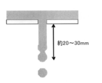
- Example 3 it is a sectional side view showing a mode that normal beer is poured out from the pore of the jig of this invention.
- Example 4 it is a sectional side view showing a mode that normal beer is poured out from the pore of the jig of this invention.
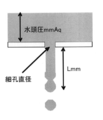
- Lmm represents the fine flow length.
- the present invention provides a beverage distribution method in which a plurality of types of beverages are supplied in a layered manner in a container and a layer structure is formed, and the top surface of the first beverage previously injected into the container is finely divided.
- the second beverage is turbulent and stirred by continuous droplets or fine flow through the porous porous plate on the upper surface of the first beverage previously injected into the container.
- the second beverage is layered while suppressing turbulence and stirring by continuous droplets or fine flow.
- a method for supplying the liquid hereinafter simply referred to as “method for supplying the beverage in a layered manner”
- the second beverage supplied through the porous porous plate reaches the liquid level in the container. It is preferable to carry out the adjustment by adjusting the liquid droplets so as to form droplets.
- adjusting the size of the pores of the porous porous plate and / or adjusting the head pressure of the second beverage in the pores of the porous porous plate As a method for performing such adjustment, as described later, adjusting the size of the pores of the porous porous plate and / or adjusting the head pressure of the second beverage in the pores of the porous porous plate. It is particularly preferable to perform the above.
- the method of supplying the beverage of the present invention in a layered manner can be performed by adjusting the size of the pores of the porous porous plate.
- “adjusting the size of the pores of the porous porous plate” includes adjusting the size of the porous porous plate with variable pore size, In the perforated porous plate having the same size, selection of an appropriate size is also included.
- the size of the pores of the porous porous plate can be adjusted as appropriate depending on the type of beverage (viscosity, etc.) supplied into the container through the pores, but in order to suppress turbulent flow and stirring, Within a suitable range of the time required to supply the beverage to be fed, it is preferable that the second beverage preferably has a liquid droplet before the second beverage reaches the liquid level in the container. Thus, it is desirable to adjust the size of the pores of the porous porous plate.
- the shape of the pores of the perforated plate can also be adjusted for this purpose, and in addition to a circle, an ellipse, a rectangle, or the like can be used, and a circle can be preferably used.
- the above-mentioned quadrangle includes slit-like pores as long and narrow quadrilaterals.
- the preferred size of the pores is the number of pores, the spacing between the pores, the height from the liquid level of the beverage previously injected into the container to the pore porous plate, the beverage in the pores of the pore porous plate
- the diameter is within the range of 0.42 to 3 mm, preferably within the range of 0.78 mm to 2.09 mm, more preferably within the range of 0.87 to 2.03 mm, even more preferably within the range of 1.02 to 1.91 mm, More preferably within the range of 1.02 to 1.72 mm, even more preferably within the range of 1.02 to 1.45 mm, more preferably within the range of 1.02 to 1.33 mm, and particularly preferably 1.15 to 1 mm. Can be illustrated as being within the range of 33 mm .
- the method of supplying the beverage of the present invention in a layered manner can be performed by adjusting the water head pressure of the second beverage in the pores of the porous porous plate, particularly the maximum water head pressure.
- Such water head pressure, particularly maximum water head pressure can be adjusted by adjusting the height, particularly the maximum height, of the second beverage accumulated on the porous porous plate in the present invention.
- the preferred height of the water head pressure includes the size of the pores, the number of pores, the spacing between the pores, the height from the liquid level of the beverage previously injected into the container to the pore porous plate, etc.
- the adjustment of the head pressure of the second beverage includes the case where the second beverage is pressurized.
- the fine pressure including the pressurized pressure (excluding atmospheric pressure) is also included.
- the method of supplying the beverage of the present invention in a layered manner can be performed by adjusting the distribution shape of the pores of the porous porous plate.
- the distribution shape of the pores of the porous porous plate include the number of pores of the porous porous plate, the distribution shape, and the spacing between the pores.
- the pores are symmetric with respect to the center of the porous porous plate from the viewpoint of further suppressing the turbulent flow / stirring on the top surface of the previously injected beverage It is preferable that the pores be arranged in the shape of the pores, and the pores having a shape distribution along the peripheral surface of the container can be cited as a more preferable pore distribution shape.
- a circular distribution can be preferably exemplified.
- the pore size, shape, number, distribution shape, pore spacing of the pore porous plate It is possible to supply the second beverage in a layered manner while suppressing turbulent flow and stirring by combining adjustment of the head pressure of the second beverage in the pores.
- the adjustment of the size of the pores and the adjustment of the head pressure of the second beverage in the pores of the pore-perforated plate are combined at least so that the second beverage becomes droplets before reaching the liquid level in the container.
- the pore size of the porous porous plate is reduced, the number of pores per unit area is reduced, the pores are spaced apart from each other, or the head pressure of the second beverage in the pores of the porous porous plate
- the head pressure of the second beverage in the pores of the porous porous plate When (especially the maximum water head pressure) is lowered, when the beverage supplied through the porous porous plate is supplied by continuous droplets or fine flow on the upper surface of the previously injected beverage, the upper surface per unit area Since the kinetic energy given per unit time decreases, the turbulent flow / stirring on the upper surface of the previously injected beverage is further suppressed.
- the layer structure can be appropriately adjusted within a range in which the beverage formed can be distributed in the reference container.
- the beverage supplied through the porous porous plate is a droplet that is continuous with the top surface of the previously injected beverage or
- the kinetic energy given to the upper surface per unit area per unit time can be effectively reduced, and as a result, the turbulent flow and agitation of the upper surface of the previously injected beverage can be reduced. It can be effectively suppressed.
- more preferable combinations are [0.42 mm, 90 to 100 mmAq], [0.48 mm, 50 to 100 mmAq], [0.59 mm, 50 to 100 mmAq], [0.69 mm, 30 to 100 mmAq], [0.78 mm, 30 to 100 mmAq], [0.87 mm, 25 to 100 mmAq], [1.02 mm, 8 to 90 mmAq], [1.15 mm, 8 to 70 mmAq], [1.33 mm, 6 to 40 mmAq], [1.45 mm, 6-30 mmAq], [1.62 mm, 6-30 mmAq], [1.72 mm, 6-25 mmAq], [1.83 mm, 6-25 mmAq], [1.91 mm, 6- 25 mmAq], [2.03 mm, 6-18 mmAq], [2.09 mm, 6-10 mmAq].
- more preferable combinations are [0.42 mm, 90 to 100 mmAq], [0.48 mm, 50 to 100 mmAq], [0.59 mm, 50 to 100 mmAq], [0.69 mm, 30 to 100 mmAq], [0.78 mm, 30 to 90 mmAq], [0.87 mm, 25 to 90 mmAq], [1.02 mm, 8 to 40 mmAq], [1.15 mm, 8 to 35 mmAq], [1.33 mm, 6 to 18 mmAq], [1.45 mm, 6-15 mmAq], [1.62 mm, 6-15 mmAq], [1.72 mm, 6-15 mmAq], [1.83 mm, 6-15 mmAq], [1.91 mm, 6- 15mmAq] and [2.03mm, 6 to 10mmAq], and more preferable combinations among the above combinations (iii) [0.42 mm, 90-100 mmAq], [0.48 mm, 50-100 mmAq], [0.48
- the preferable head pressure range corresponding to the diameter of any pore in the range of 0.42 to 2.09 mm not described in these preferable combinations is a numerical value calculated from the above preferable combination.
- a range can be mentioned.
- the diameter of any pore in the range of 0.42 to 2.09 mm that is not described in the above preferred combination is X2 (mm)
- the diameters of the two pores closest to X2 are X1 (mm) and X3 (mm) (where X1 ⁇ X2 ⁇ X3)
- the range of hydraulic head pressure corresponding to X1 in the above preferred combination is Y1 to Y1 ′ ( Considering the case where the range of hydraulic head pressure corresponding to X3 is Y3 to Y3 ′ (mmAq), the lower limit value Y2 and the upper limit in the preferable hydraulic head pressure range Y2 to Y2 ′ (mmAq) corresponding to X2
- the value Y2 ′ include those calculated by
- Y2 Y1 + (X2-X1) ⁇ (Y3-Y1) / (X3-X1):
- Y2 ′ Y1 ′ + (X2 ⁇ X1) ⁇ (Y3′ ⁇ Y1 ′) / (X3 ⁇ X1):
- the second beverage Can be appropriately set depending on the distance from the liquid surface of the second beverage to the porous porous plate when the is finally supplied.
- the fine flow length it is preferable to adjust the fine flow length to be shorter than the distance from the liquid level in the container to the porous porous plate, and the container for supplying the beverage Is a normal beer glass (about 12 to 18 cm in height), it is preferable to adjust the fine flow length to 40 mm or less, and if the container is larger than that, the fine flow length can be adjusted accordingly.
- the height from the liquid level of the beverage previously injected into the container to the porous porous plate is not particularly limited, but is, for example, in the range of 1 to 20 cm, preferably in the range of 5 to 15 cm. Can be mentioned.
- the distance from the liquid level of the second beverage to the perforated porous plate when the second beverage is finally supplied is not particularly limited, but for example 0.1 to 10 cm, preferably 1 to 8 cm, more preferably 2 to 6 cm.
- the second beverage of the upper layer is likely to be mixed with the first beverage of the lower layer, particularly at the beginning of supply, the upper beverage is first supplied through the perforated porous plate in small portions. If a certain level of the inner upper beverage is secured, a method of increasing the supply amount of the upper beverage per unit time can be preferably cited.
- the second beverage Is adjusted so that it becomes liquid droplets before reaching the liquid level in the container, and if the beverage in the upper layer in the container is secured to a certain level, within a range where a beverage having a layered structure can be obtained
- a supply method in which the second beverage reaches the liquid level in the container in a fine flow.
- the elements in the porous porous plate whose adjusting elements are variable
- it also includes selecting appropriate elements in the porous perforated plate where these adjustments are unchanged.
- the pore porous plate may have only pores having the same size and shape, or may have two or more different sizes and shapes of pores.
- the preferred number of pores includes the size of the pores, the shape of the pores, the spacing between the pores, the height from the liquid level of the beverage previously injected into the container to the porous pore plate, the pore porosity Since it depends on the water head pressure of the beverage in the pores of the plate, the viscosity of the beverage, etc., it cannot be generally stated, but 1 to 20, preferably 5 to 15, more preferably 8 to 12 may be exemplified. it can.
- the preferred spacing between the pores is the size of the pores, the shape of the pores, the number of pores, the height from the liquid level of the beverage previously injected into the container to the porous porous plate, the pore porosity Since it depends on the water head pressure of the beverage in the pores of the plate, the viscosity of the beverage, etc., it cannot be generally stated, but 5 to 30 mm, preferably 8 to 25 mm, more preferably 10 to 20 mm can be exemplified.
- the plurality of kinds of beverages means two or three or more kinds of beverages having no difference in specific gravity or two or more kinds of beverages having a difference in specific gravity, and preferably have a difference in specific gravity.
- the type of the beverage is not particularly limited, and may be an alcoholic beverage or a soft drink, but preferably applicable beverages include beer, sparkling liquor, beer-like beverages, other miscellaneous alcoholic beverages, liqueurs, and soft drinks.
- Etc. can be mentioned as beverages to which more preferably can be applied.
- Preferred examples of the soft drink include soft drinks such as cola, tomato juice, and milk.
- the plurality of types of beverages preferably have a color difference, but may not have a color difference.
- the color means one or more of hue, saturation, and brightness.
- the specific gravity of a drink can be measured by a well-known method. Examples of such a measuring method include the method described in JIS Z8804 “Measurement method of density and specific gravity of liquid”.
- the method of dispensing a beverage having a layer structure includes a jig container part comprising a peripheral wall and a jig bottom made of a porous porous plate, and the jig container part for placing the jig container part on the upper part of the container. Even if it is a beverage of relatively specific gravity, it is easy and reliable for anyone, even if it is a beverage with a relatively close specific gravity, using a jig that consists of a support and is used to distribute beverages with a layered structure. In addition, the beverage having a layered structure can be dispensed into the container.
- the jig of the present invention is a jig for supplying a plurality of types of beverages in a layered manner in a container, and for distributing the beverage having a layered structure into the container, as shown in FIG. Further, a jig container part composed of a peripheral wall (1-1) and a jig bottom part (1-2) made of a porous porous plate, and a support part (2 for placing the jig container part on the upper part of the container -1).
- the jig container part is composed of an outer peripheral wall (1-1) and a jig bottom part (1-2) made of a porous porous plate, and the jig container part has a certain amount injected into the container through the jig. It has a capacity to accommodate beverages.
- the shape of the jig container is not particularly limited as long as the beverage can be put into the jig container and the beverage can be made into a continuous liquid droplet or a fine flow through the porous porous plate.
- the jig bottom is preferably circular in plan view
- the outer peripheral wall bottom is preferably circular in plan view accordingly.
- the outer peripheral wall preferably extends in a tapered shape from the bottom of the outer peripheral wall to the top of the outer peripheral wall.
- the jig bottom may not be a flat surface and may include a concave portion or a convex portion, but it is preferably a flat surface in order to apply an average hydraulic pressure to the porous porous plate.
- the height of the outer peripheral wall of the jig container is appropriately adjusted according to the capacity of the beverage to be injected into the container and the maximum water head pressure of the second beverage in the pores of the porous porous plate.
- the capacity in the jig container increases, and in order to pour the second beverage into the jig container, a large amount is accommodated in the container, and the frequency of pouring the beverage into the jig container part is reduced.
- the operation of the distribution method becomes simpler.
- the height of the beverage that can be put in the jig container also increases when the outer peripheral wall is raised, if the second beverage is put in the jig container more than necessary, the pore porous plate in the jig container Depending on the viscosity of the beverage, the water head pressure of the beverage in the pores will increase, and as a result, the momentum of the fine flow of the beverage supplied through the porous porous plate will increase and the fine flow length will become too long. obtain. Therefore, it is preferable that the height of the outer peripheral wall is appropriately adjusted within a range in which the beverage in which the layer structure is formed can be distributed in the citation container.
- the preferred height of the outer peripheral wall is the size of the pores, the shape of the pores, the number of pores, the spacing between the pores, from the liquid level of the beverage previously injected into the container to the porous porous plate. Although it depends on the height, the viscosity of the beverage and the like, it cannot be said unconditionally. A range of 40 mm can be exemplified.
- the jig container part preferably further includes a spout for pouring the beverage remaining in the jig container part and / or its foam into the container. Further, the shape and size of the jig bottom can be appropriately adjusted in accordance with the shape and size of the container.
- the pore perforated plate has a plurality of pores, and the size, shape, number, distribution shape, and pores of the pores can be used as long as the beverage can be a continuous droplet or a fine flow through the pores. There are no particular restrictions on the interval between the two.
- the preferred size, preferred shape, preferred number of pores, and preferred spacing between the pores can be appropriately determined according to the properties (viscosity, etc.) of the beverage injected into the container through the jig.
- As a preferable distribution shape of the pores from the viewpoint of further suppressing the turbulent flow / stirring on the top surface of the previously injected beverage, it is arranged so that the pores are targeted with respect to the center of the porous porous plate.
- porous porous plate may have only pores having the same size and shape, or may have two or more different sizes and shapes of pores.
- the jig of this invention has a support part (2-1) for mounting a jig container part on the upper part of a container.
- the shape of the support portion is not particularly limited, and examples thereof include a plate shape.
- the jig container portion in a plan view so that the jig container portion can be placed on the upper portion of the container.
- the thing of the structure extended toward the outer side from can be mentioned.
- a design change can be appropriately made as a structure that can be stably placed on the upper part of the container based on the structure.
- the container fitting groove (2-1-1) is not particularly limited as long as it is a groove that fits in the upper part of the container so that the jig can be stably placed on the upper part of the container. It is preferable that the groove has a wide width so that In this case, the container fitting groove (2-1-1) does not fit in the upper part of the container without a strict sense, but for convenience, such an aspect is also included in the “fitting” in the present invention. In addition, when installing a support part in two places, you may give a wide width
- the support part (2-1) of the jig of the present invention includes a container fitting groove (2-1-1) for stably placing the jig on the upper part of the container, and a jig holding the jig to place the jig on the upper part of the container.
- a gripping part (2-2) for placing or removing can be provided.
- the gripping part may be formed integrally with a support part for placing on the upper part of the container, and both may be combined to form a support.
- the support portion (2-1) can be provided with a separation groove for preventing a droplet or fine flow of the second beverage from being transmitted to the support portion.
- the separation groove is a groove that can prevent the droplet or fine flow of the second beverage from being transmitted to the support portion
- its structure can be changed as appropriate.
- the provided structure can be mentioned as a preferable structure.
- the cover part which covers the opening part of a container can be provided in the jig container part and / or support part of this invention.
- Such a lid is preferable because it can prevent the beverage from flowing into the container when the second beverage is excessively poured into the jig container and overflows.
- Such a lid portion may not cover the entire surface of the opening of the container, but preferably covers the entire surface. Note that such a lid may be provided in the gripper, or the lid itself may be used as the gripper.
- the beverage having the largest specific gravity is normally poured into the container to form the first layer (lowermost layer).
- the jig of the present invention is placed in the opening of the container.
- a beverage having the next highest specific gravity (the second layer beverage) is poured into the jig container part of the jig of the present invention after the first layer beverage
- the droplets in which the second layer beverage continues through the porous porous plate or It is supplied into the container by a fine flow (preferably so that it becomes a droplet before the second layer of beverage reaches the liquid level in the container), and the second layer is formed on the upper surface of the first layer of beverage in the container.
- the first beverage in the present invention is particularly preferably a beverage having a higher specific gravity
- the second beverage is particularly preferably a beverage having a lower specific gravity.
- the first beverage and the second beverage do not correspond to one type of beverage, respectively, and each corresponds to a plurality of types of beverage.
- a beverage having a three-layer structure is prepared by pouring three kinds of beverages P, Q, and R in this order, first, P is injected into the container as a first beverage, and Q is placed thereon. Is supplied as a second beverage. Next, the Q is now the first beverage, on which R is supplied as the second beverage.
- the jig container portion of the jig of the present invention is provided with a mark such as a line representing how many mm or less the fine flow length can be made if the second beverage poured into the jig container portion is below this height.
- the mark is preferably provided, and as such a mark, for example, a mark that can make the fine flow length about 60 mm or less, a mark that can make the fine flow length about 40 mm or less, and the second beverage are poured out from the pores
- the mark which can be made into a droplet at the time of doing can be mentioned preferably.
- the height of the jig container portion to which these marks are to be applied is a preferable combination of the aforementioned pore diameter and the range of the head pressure of the second beverage, and a numerical range calculated from such a preferable combination. It can be set by referring.
- the height (mm) of the mark indicating that the fine flow length can be 60 mm or less is the head pressure (2) of the second beverage selected or calculated from the combination (i) according to the diameter of the pores.
- the upper limit value in the range of mmAq) can be a value (mm) divided by the specific gravity of the second beverage, and the height (mm) of the mark indicating that the fine flow length can be 40 mm or less is thin.
- the upper limit of the range of the head pressure (mmAq) of the second beverage selected or calculated from the combination (ii) according to the diameter of the hole may be a value (mm) divided by the specific gravity of the second beverage.
- the height (mm) of the mark indicating that the second beverage can be formed into a droplet at the time when the second beverage is dispensed from the pore is selected or calculated from the combination (iii) according to the diameter of the pore.
- the value obtained by dividing the upper limit of the range of water head pressure (mmAq) of two beverages by the specific gravity of the second beverage ( It can be a m).
- the water head pressure needs to be 40 mmAq or less, so that the specific gravity of the second beverage is 1.1.
- a mark can be placed at a height of 36.4 mm (40 / 1.1) of the jig container.
- the jig of the present invention comprises a jig container part comprising a peripheral wall (1-1) and a jig bottom part (1-2) made of a porous porous plate, and the jig container part at the upper part of the container.
- a jig for supplying a plurality of types of beverages in a layered manner in a container and distributing the beverages in a layered structure in a container, comprising a support part (2-1) for placing on the container is there.
- the jig bottom (1-2) has a circular planar shape in plan view.
- the outer peripheral wall (1-1) extends in a taper shape from the outer peripheral wall bottom (1-1-2) to the outer peripheral wall top (1-1-1).
- Plural pores (1-3) in the perforated plate of the jig bottom (1-2) are arranged in a circular shape at regular intervals along the outer peripheral edge of the circular jig bottom (1-2) Has been.
- the jig container part includes a support part (2-1) on the outer peripheral wall bottom part (1-1-2) for placing the jig container part on the upper part of the container.
- the support portion (2-1) extends outward from the jig container portion at two locations facing the center of the jig container portion in plan view.
- the support part (2-1) further includes a grip part (2-2) for gripping the jig and placing or removing the jig on the upper part of the container, and the support part (2) ) Is formed.
- the support part (2-1) includes a container fitting groove (2-1-1) for stably placing the jig on the upper part of the container, and a droplet or a fine flow that has passed through the pores. It has a separate groove (2-1-2) to prevent it from being transmitted to
- the container fitting groove (2-1-1) and the separation groove (2-1-2) are attached only to the support part (2) on one side (III in FIG. 1). (2-1-1) and the separation groove (2-1-2) are also provided in the support portion (2) on the opposite side.
- the height of the jig container was 29 mm
- the diameter of the jig bottom was 45 mm
- the diameter when the outer peripheral wall top was viewed in plan was about 58 mm.
- the pores were tapered toward the container (taper angle 20 °), and the diameter of the hole at the tip was 1 mm.
- Example 2 When a test was performed using the jig of the present invention described in Example 1 having 10 pores having a diameter of 1 mm, a two-layer beer in which a black beer layer and a normal beer layer were clearly separated was produced. (See Fig. 2).
- a beverage having a layer structure can be distributed in a container such as a drinking container.
- Example 2 [In-container distribution test for beverages with layered structure 2] Using the jig of the present invention described in Example 1, a beverage distribution test in which a layered structure was formed was further performed. For this test, the jig of the present invention described in Example 1 having 10 pores having a diameter of 1 mm was used and the same method as in Example 2 was performed. At that time, black beer (first beverage) from the bottom of the jig at the time when normal beer (second beverage) starts to be poured into the glass (height 15.1 cm) (hereinafter referred to as “injection start time”).
- injection height The height to the upper surface (hereinafter referred to as “injection height”) was 70 mm, and the diameter of the upper surface of the black beer at the start of the injection was also 70 mm.
- Ordinary beer was poured several times to the extent that the jig container of the jig of the present invention was almost filled. As a result, the interface between the two beers was not disturbed until the liquid level of the normal beer being poured rose to about 20 to 30 mm to the bottom of the jig, but the liquid level of the normal beer further increased and the bottom of the jig When approaching, the interface between the two beers was disturbed and mixed.
- the normal beer poured from the jig of the present invention is not a droplet but a fine stream until it falls about 20 to 30 mm from the pore at the bottom of the jig, It turned out that it changed into the droplet at the front-end
- the normal beer poured into the liquid surface changes from a droplet to a fine flow, thereby causing the normal beer liquid level It was found that convection occurred in the vicinity, the convection reached the interface between normal beer and black beer, and the interface was disturbed to cause mixing of both beers.
- Example 3 From the series of test results of Example 3, whether or not the turbulent flow and stirring of the beverage in the container can be suppressed and the two-layer beer can be produced depends on the injection height and the number of pores at the start of the second beverage injection. And the distribution, the supply flow rate per unit time of the second beverage, etc., but it is particularly important whether the second beverage is a fine flow or a droplet when reaching the liquid level in the container, It was shown that the size of the pores and the water head pressure of the second beverage in the pores are important for whether the second beverage reaches the liquid level in the container. . If it is a droplet when the second beverage reaches the liquid level in the container, the turbulent flow / stirring of the beverage in the container can be suppressed.
- the jig container part was extended in the height direction so that the water head pressure in the pores could be increased to 100 mmAq.
- a jig of the present invention was fixed above the glass with a stand and a clamp.
- Normal beer is poured into the jig container, and the vertical length of the fine flow from the fine flow of normal beer poured from the pores to the separation of the droplet (the length from the bottom of the jig to the tip of the fine flow) ("Lmm") (see Fig. 4) was visually measured using a ruler. The results are shown in Table 1.
- the present invention relates to a method of distributing a beverage in a container in a layered manner when the beverage is distributed and served in a container such as a drinking container at the time of drinking or in a restaurant, etc., and the layer structure of the beverage in the container Provide jigs to perform the distribution.
- the method for dispensing a beverage having a layered structure according to the present invention into a container requires skill in the technology even if the beverage has a relatively similar specific gravity by using a jig for carrying out the dispensing.
- anyone can easily and surely distribute a beverage having a layered structure in a container, so that when drinking or serving a beverage in a container such as a drinking container at a restaurant, etc. It is possible to provide a multi-layered container-packed beverage that is easy and rich in palatability.
Landscapes
- Engineering & Computer Science (AREA)
- Food Science & Technology (AREA)
- Table Devices Or Equipment (AREA)
- Devices For Dispensing Beverages (AREA)
- Apparatus For Making Beverages (AREA)
Abstract
本発明の課題は、飲用時或いはレストラン等で、飲料を飲用容器等の容器に分配して給仕する際に、容器内へ飲料を層状になるように分配する方法及び該容器内への飲料の層構造分配を行うための冶具を提供すること等にある。本発明の解決手段は、外周壁と細孔多孔板からなる冶具底部とからなる冶具容器部と、該冶具容器部を、容器の上部に載置するための支持部とからなる、複数種の飲料を、容器内に層状になるように供給し、層構造を形成した飲料の容器内分配を行うための冶具を用いる点等にある。
Description
本発明は、飲用時或いはレストラン等で、飲料を飲用容器等の容器に分配して給仕する際に、容器内へ飲料を層状になるように分配する方法及び該容器内への飲料の層構造分配を行うための冶具に関する。
飲食店等では様々な飲料が提供されている。飲料の提供に際して、その嗜好性を増大するために、カクテルや、フロートタイプ、トッピングタイプのような、その味覚と共に、形状的な視覚に訴えて、その嗜好性を高めることも行われている。視覚的な美しさに特徴を持たせた飲料の飲用容器での提供方法として、従来より、カクテルが知られている。その提供方法の1つとして、多層形状に分配されたカクテルが知られている。カクテルの分野ではこのような多層のカクテルは、プースカフェスタイルと総称されていて、以前より広く知られている。カクテルでは、このように多層形状に分配されたものが提供され、視覚的な美しさに特徴を持たせて、消費者に受け入れられているが、このような多層形状に分配された飲料は、グラス内に色及び比重の異なる複数種の飲料が、その比重差を利用して、飲料毎に層状に積み重ねられたものである。
従来より、多層カクテルを作製する場合には、以下のような方法が用いられてきた。まず、用いる飲料のうち、比重が最も高い飲料をグラス内に普通に注いで1層目(最下層)を形成する。次いで、次に比重の重い飲料を、1層目の飲料と混合しないようにグラス内に静かに注いで2層目を形成する。用意した種類の飲料をすべて用いるまで、2層目と同様の注ぎ工程を繰り返す。ここで2層目以降の飲料をグラス内に静かに注ぐために、マドラーと呼ばれる飲料攪拌用の棒や、バースプーン(特許文献1)と呼ばれる細長いスプーンの先端をグラス内側の壁面に接触させ、飲料をマドラーやバースプーンを伝わせてグラス内側の壁面に少量ずつ注ぐことが行われていた。しかし、マドラーやバースプーンを用いたこの方法は、技術の熟練が相当程度必要であり、簡便性などの点で問題がある他、該多層カクテルの分配に用いられている手法を、他のどの飲料にも適用できるというものではなかった。
近年、カクテルのような分野とは異なる飲料の分野で、飲用容器に多層形状で飲料を分配して提供する方法が提案されている。例えば、特許文献2には、コーヒーやミルクなどの濃縮液を用いて、2層以上の液体の層を備えた飲料を容器内に分配する方法が開示されている。この方法は、第一の濃縮液の少なくとも1個の供給源と、第二の濃縮液の少なくとも1個の供給源とを用意し、第一の濃縮液の供給源から希釈されて飲用容器に供給された飲料の上方に、該液体層の濃度より低い濃度まで希釈された第二の液体を供給して、層状の液体の層を形成するものである。この方法では、濃縮液の水による希釈率を制御し、上層の液体における希釈率を下層の液体における希釈率よりも高くすること、及び、液体を容器内に静かに供給することなどによって、上層が下層の上に留まるように飲料を分配するものであるが、かかる方法は濃縮液を利用する場合等、特定の飲料の提供の場合に限られている上、第一の液体層及び第二の液体層が乱流を起こさないように、第二の液体の流量を調整して、静かに送給するにしても、上記のような場合以外の飲料に適用した場合に、ただそれだけで、層状に分配された飲用容器入り飲料を提供することは難しく、したがって、この開示の方法は、限られた飲料の場合にのみ、適用できるものである。
また、最近、その比重が近似するビール等において、より簡便に2層ビールを作製するための冶具が考案され、ビールと共に消費者に提供されている。かかる従来の冶具(以下、「従来冶具」と表示する。)は、容器の開口部に冶具を載置するための支持体と、飲料を上から注ぐための部分球面形状(非常に浅いお椀を伏せたような形状)部とからなる。1層目のビールを注いだグラスの開口部に従来冶具をセットした後、その部分球面形状の頂部付近から2層目のビールを注ぐと、ビールが部分球面形状の周囲に拡散しながらグラス内に静かに注がれ、それによって、2層目のビールと1層目のビールが混合されるのを抑制し、層構造を形成するというのが従来冶具の狙いであった。しかし、従来冶具で2層ビールを上手く作製するには、2層目のビールを従来冶具の頂部付近に、均等かつ安定的に、静かに注ぎ続ける必要があり、クリアーな層構造のビールを分配するには依然として相当の熟練が必要であった。すなわち、容器入りのビールを同じ位置で同じ角度に傾けても、ビールの残量などによってビールの流下する位置が変動してしまうため、使用する者の技術の熟練度などによっては、ビールが従来冶具の部分球面形状の表面に十分に拡散せず、2層ビールを作製できないだけでなく、冶具の球面形状の頂部を流下する薄層の液は、冶具から流下する時点で、幾筋かに集液する性質があり、液体の本質的な特性から、上記のような冶具を用いて、クリアーな層構造のビールを分配することは難しいという問題があった。
本発明の課題は、飲用時或いはレストラン等で、飲料を飲用容器等の容器に分配して給仕する際に、容器内へ飲料を層状に分配する方法及び該容器内への飲料の層構造分配を行うための冶具を提供することにあり、特に、比較的比重の近似する飲料の分配にも適用でき、技術の熟練を要さず、誰でも簡単かつ確実に、層構造を形成した飲料を容器内に分配する方法及びそのような分配を行うための冶具を提供することにある。
本発明者らは、上記課題を解決すべく、ビールの場合のような、比較的比重の近似する飲料の分配にも適用でき、技術の熟練を要さず、誰でも簡単かつ確実に、層構造を形成した飲料を容器内に分配するための冶具について、鋭意検討する中で、様々な形状の冶具を試作し、その検証を行った結果、外周壁と細孔多孔板からなる冶具底部とからなる冶具容器部と、該冶具容器部を、容器の上部に載置するための支持部とからなる冶具を用い、容器内に先に注入された第1飲料の上面に、細孔多孔板を通して、第2飲料を連続する液滴或いは微細流により、乱流・攪拌を抑制しながら供給することにより、層状になるように供給することが可能となり、該方法により、比較的比重の近似する飲料であっても、技術の熟練を要さず、誰でも簡単かつ確実に、層構造を形成した飲料を容器内に分配できることを見いだし、本発明を完成するに至った。
すなわち、本発明は、複数種の飲料を、容器内に層状になるように供給し、層構造を形成した飲料の容器内分配方法において、容器内に先に注入された第1飲料の上面に、細孔多孔板を通して、第2飲料を連続する液滴或いは微細流により、乱流・攪拌を抑制しながら、層状になるように供給することを特徴とする層構造を形成した飲料の容器内分配方法からなる。
本発明の飲料の容器内分配方法において、第2飲料を連続する液滴或いは微細流により、乱流・攪拌を抑制しながら、層状になるように供給する方法としては、細孔多孔板を通して供給される第2飲料が容器内の液面に到達するまでに液滴となるように調節することにより好適におこなうことができる。また、細孔多孔板を通して供給される第2飲料が容器内の液面に到達するまでに液滴となるように調節することは、細孔多孔板の細孔の大きさを調節することや、細孔多孔板の細孔における第2飲料の水頭圧を調節することにより行うことできる。
本発明の飲料の容器内分配方法において、第2飲料を連続する液滴或いは微細流により、乱流・攪拌を抑制しながら、層状になるように供給する方法は、外周壁を有する容器の底部を細孔多孔板とした冶具を用いて行うことができる。
本発明の飲料の容器内分配方法を適用することができる飲料として、ビール、発泡酒、ビール様飲料、その他の雑酒、リキュール及びソフトドリンクを挙げることができる。
本発明は、外周壁と細孔多孔板からなる冶具底部とからなる冶具容器部と、該冶具容器部を、容器の上部に載置するための支持部とからなる、複数種の飲料を、容器内に層状になるように供給し、層構造を形成した飲料の容器内分配を行うための冶具の発明を包含する。
該層構造を形成した飲料の容器内分配を行うための冶具の冶具容器部底部の細孔多孔板の複数の細孔は、第2飲料を乱流・攪拌を抑制しながら、層状に供給するために、円形冶具底部の外周端部に沿って、円形状に配置されている構造のものを特に好ましい構造として挙げることができる。
本発明の飲料の容器内分配を行うための冶具において、冶具容器部は、容器の上部に載置するための支持部に、冶具を容器上部に安定して載置するための容器嵌合溝を形成した構造とすることができる。また、該冶具容器部は、容器の上部に載置するための支持部に、第2飲料の液滴或いは微細流が支持部に伝わらないようにするためのセパレート用溝を設けた構造とすることができる。更に、冶具容器部を容器の上部に載置するための支持部は、冶具を把持して冶具を容器上部に載置或いは取り外すための把持部を備えることができる。
すなわち具体的には本発明は、(1)複数種の飲料を、容器内に層状になるように供給し、層構造を形成した飲料の容器内分配方法において、容器内に先に注入された第1飲料の上面に、細孔多孔板を通して、第2飲料を連続する液滴或いは微細流により、乱流・攪拌を抑制しながら、層状になるように供給することを特徴とする層構造を形成した飲料の容器内分配方法や、(2)第2飲料を連続する液滴或いは微細流により、乱流・攪拌を抑制しながら、層状になるように供給する方法を、細孔多孔板を通して供給される第2飲料が容器内の液面に到達するまでに液滴となるように調節することにより行うことを特徴とする上記(1)に記載の層構造を形成した飲料の容器内分配方法や、(3)細孔多孔板を通して供給される第2飲料が容器内の液面に到達するまでに液滴となるように調節することを、細孔多孔板の細孔の大きさを調節すること、及び/又は、細孔多孔板の細孔における第2飲料の水頭圧を調節することにより行うことを特徴とする上記(2)に記載の層構造を形成した飲料の容器内分配方法や、(4)第2飲料を連続する液滴或いは微細流により、乱流・攪拌を抑制しながら、層状になるように供給する方法を、外周壁を有する容器の底部を細孔多孔板とする冶具により行うことを特徴とする、上記(1)~(3)のいずれかに記載の層構造を形成した飲料の容器内分配方法や、(5)細孔多孔板の細孔から注出する第2飲料の微細流から液滴が分離するまでの微細流の垂直方向の長さを60mm以下に調節するために、前記細孔の直径に応じて以下の(i)の組合せから選択又は算出される第2飲料の水頭圧の範囲内になるように、該水頭圧を調節し、前記長さを40mm以下に調節するために、前記細孔の直径に応じて以下の(ii)の組合せから選択又は算出される第2飲料の水頭圧の範囲内になるように、該水頭圧を調節し、又は、前記第2飲料が細孔から注出する時点で液滴であるように調節するために、前記細孔の直径に応じて以下の(iii)の組合せから選択又は算出される第2飲料の水頭圧の範囲内になるように、該水頭圧を調節することを特徴とする上記(1)~(4)のいずれかに記載の層構造を形成した飲料の容器内分配方法:
(i)[0.42mm、90~100mmAq]、[0.48mm、50~100mmAq]、[0.59mm、50~100mmAq]、[0.69mm、30~100mmAq]、[0.78mm、30~100mmAq]、[0.87mm、25~100mmAq]、[1.02mm、8~90mmAq]、[1.15mm、8~70mmAq]、[1.33mm、0~40mmAq]、[1.45mm、0~30mmAq]、[1.62mm、0~30mmAq]、[1.72mm、0~30mmAq]、[1.83mm、0~25mmAq]、[1.91mm、0~25mmAq]、[2.03mm、0~18mmAq]、[2.09mm、0~10mmAq]:
(ii)[0.42mm、90~100mmAq]、[0.48mm、50~100mmAq]、[0.59mm、50~100mmAq]、[0.69mm、30~100mmAq]、[0.78mm、30~90mmAq]、[0.87mm、25~90mmAq]、[1.02mm、8~40mmAq]、[1.15mm、8~35mmAq]、[1.33mm、0~18mmAq]、[1.45mm、0~15mmAq]、[1.62mm、0~15mmAq]、[1.72mm、0~15mmAq]、[1.83mm、0~15mmAq]、[1.91mm、0~15mmAq]、[2.03mm、0~10mmAq]:
(iii)[0.42mm、90~100mmAq]、[0.48mm、50~100mmAq]、[0.59mm、50~70mmAq]、[0.69mm、30~40mmAq]、[0.78mm、30~40mmAq]、[0.87mm、25~30mmAq]、[1.02mm、8~15mmAq]、[1.15mm、8~15mmAq]、[1.33mm、0~12mmAq]、[1.45mm、0~10mmAq]、[1.62mm、0~10mmAq]、[1.72mm、0~10mmAq]、[1.83mm、0~10mmAq]、[1.91mm、0~8mmAq]、[2.03mm、0~8mmAq]:ただし、(i)~(iii)の各組合せに記載されていない、0.42~2.09mmの範囲内のいずれかの細孔の直径X2に対応する水頭圧の範囲Y2~Y2’における下限値Y2及び上限値Y2’は、上記の(i)~(iii)のいずれかの組合せにおける細孔の直径のうち、X2に最も近い2つの細孔の直径をX1(mm)、X3(mm)とし(ただし、X1<X2<X3)、前記X1に対応する水頭圧の範囲をY1~Y1’(mmAq)とし、前記X3に対応する水頭圧の範囲がY3~Y3’(mmAq)としたときに、それぞれ以下のような一次関数により算出される数値を表す:
Y2=Y1+(X2-X1)×(Y3-Y1)/(X3-X1):
Y2’=Y1’+(X2-X1)×(Y3’-Y1’)/(X3-X1)や、
(6)複数種の飲料が、ビール、発泡酒、ビール様飲料、その他の雑酒、リキュール又はソフトドリンクであることを特徴とする上記(1)~(5)のいずれかに記載の層構造を形成した飲料の容器内分配方法からなる。
(i)[0.42mm、90~100mmAq]、[0.48mm、50~100mmAq]、[0.59mm、50~100mmAq]、[0.69mm、30~100mmAq]、[0.78mm、30~100mmAq]、[0.87mm、25~100mmAq]、[1.02mm、8~90mmAq]、[1.15mm、8~70mmAq]、[1.33mm、0~40mmAq]、[1.45mm、0~30mmAq]、[1.62mm、0~30mmAq]、[1.72mm、0~30mmAq]、[1.83mm、0~25mmAq]、[1.91mm、0~25mmAq]、[2.03mm、0~18mmAq]、[2.09mm、0~10mmAq]:
(ii)[0.42mm、90~100mmAq]、[0.48mm、50~100mmAq]、[0.59mm、50~100mmAq]、[0.69mm、30~100mmAq]、[0.78mm、30~90mmAq]、[0.87mm、25~90mmAq]、[1.02mm、8~40mmAq]、[1.15mm、8~35mmAq]、[1.33mm、0~18mmAq]、[1.45mm、0~15mmAq]、[1.62mm、0~15mmAq]、[1.72mm、0~15mmAq]、[1.83mm、0~15mmAq]、[1.91mm、0~15mmAq]、[2.03mm、0~10mmAq]:
(iii)[0.42mm、90~100mmAq]、[0.48mm、50~100mmAq]、[0.59mm、50~70mmAq]、[0.69mm、30~40mmAq]、[0.78mm、30~40mmAq]、[0.87mm、25~30mmAq]、[1.02mm、8~15mmAq]、[1.15mm、8~15mmAq]、[1.33mm、0~12mmAq]、[1.45mm、0~10mmAq]、[1.62mm、0~10mmAq]、[1.72mm、0~10mmAq]、[1.83mm、0~10mmAq]、[1.91mm、0~8mmAq]、[2.03mm、0~8mmAq]:ただし、(i)~(iii)の各組合せに記載されていない、0.42~2.09mmの範囲内のいずれかの細孔の直径X2に対応する水頭圧の範囲Y2~Y2’における下限値Y2及び上限値Y2’は、上記の(i)~(iii)のいずれかの組合せにおける細孔の直径のうち、X2に最も近い2つの細孔の直径をX1(mm)、X3(mm)とし(ただし、X1<X2<X3)、前記X1に対応する水頭圧の範囲をY1~Y1’(mmAq)とし、前記X3に対応する水頭圧の範囲がY3~Y3’(mmAq)としたときに、それぞれ以下のような一次関数により算出される数値を表す:
Y2=Y1+(X2-X1)×(Y3-Y1)/(X3-X1):
Y2’=Y1’+(X2-X1)×(Y3’-Y1’)/(X3-X1)や、
(6)複数種の飲料が、ビール、発泡酒、ビール様飲料、その他の雑酒、リキュール又はソフトドリンクであることを特徴とする上記(1)~(5)のいずれかに記載の層構造を形成した飲料の容器内分配方法からなる。
また、本発明は、(7)外周壁と細孔多孔板からなる冶具底部とからなる冶具容器部と、該冶具容器部を、容器の上部に載置するための支持部とからなる複数種の飲料を、容器内に層状になるように供給し、層構造を形成した飲料の容器内分配を行うための冶具や、(8)冶具容器部底部の細孔多孔板の複数の細孔が、円形冶具底部の外周端部に沿って、円形状に配置されていることを特徴とする上記(7)に記載の層構造を形成した飲料の容器内分配を行うための冶具や、(9)冶具容器部を、容器の上部に載置するための支持部に、冶具を容器上部に安定して載置するための容器嵌合溝を形成したことを特徴とする上記(7)又は(8)に記載の層構造を形成した飲料の容器内分配を行うための冶具や、(10)冶具容器部を、容器の上部に載置するための支持部に、第2飲料の液滴或いは微細流が支持部に伝わらないようにするためのセパレート用溝を設けてなる上記(7)~(9)のいずれかに記載の層構造を形成した飲料の容器内分配を行うための冶具や、(11)冶具容器部を、容器の上部に載置するための支持部が、冶具を把持して冶具を容器上部に載置或いは取り外すための把持部を備えることを特徴とする上記(7)~(10)のいずれかに記載の層構造を形成した飲料の容器内分配を行うための冶具からなる。
本発明は、飲用時或いはレストラン等で、飲料を飲用容器等の容器に分配して給仕する際に、容器内へ飲料を層状になるように分配する方法及び該容器内への飲料の層構造の分配を行うための冶具を提供する。特に、本発明の層構造を形成した飲料を容器内に分配する方法は、該分配を行うための冶具を用いることにより、比較的比重の近似する飲料であっても、技術の熟練を要さず、誰でも簡単かつ確実に、層構造を形成した飲料を容器内に分配することが可能であるので、飲用時或いはレストラン等で、飲料を飲用容器等の容器に分配して給仕する際に、手軽に、嗜好性に富んだ、多層構造の容器入り飲料を提供することができる。
本発明は、複数種の飲料を、容器内に層状になるように供給し、層構造を形成した飲料の容器内分配方法において、容器内に先に注入された第1飲料の上面に、細孔多孔板を通して、第2飲料を連続する液滴或いは微細流により、乱流・攪拌を抑制しながら、層状になるように供給することからなる層構造を形成した飲料の容器内分配方法、及びそのための冶具からなる。
本発明の飲料の容器内分配方法においては、容器内に先に注入された第1飲料の上面に、細孔多孔板を通して、第2飲料を連続する液滴或いは微細流により、乱流・攪拌を抑制しながら、層状になるように供給されるが、かかる飲料の容器内への分配方法において、第2飲料を連続する液滴或いは微細流により、乱流・攪拌を抑制しながら、層状になるように供給する方法(以下、単に「飲料を層状になるように供給する方法」とも表示する。)としては、細孔多孔板を通して供給される第2飲料が容器内の液面に到達するまでに液滴となるように調節することによって行うことを好適に挙げることができる。かかる調節を行う方法としては、後述するような、細孔多孔板の細孔の大きさを調節すること、及び/又は、細孔多孔板の細孔における第2飲料の水頭圧を調節することによって行うことなどを特に好適に挙げることができる。
本発明の飲料を層状になるように供給する方法は、細孔多孔板の細孔の大きさを調節することによって行うことができる。なお、本明細書における「細孔多孔板の細孔の大きさを調節する」ことには、細孔の大きさが可変の細孔多孔板においてその大きさを調節することの他、細孔の大きさが不変の細孔多孔板において、適切な大きさのものを選択することも含まれる。
細孔多孔板の細孔の大きさは、細孔を通して容器内へ供給する飲料の種類(粘度等)によって、適宜、調節することができるが、乱流・攪拌を抑制するために、容器内へ供給する飲料の供給に要する時間の適当な範囲内で、連続する液滴或いはなるべく微細の液流となるように、好ましくは第2飲料が容器内の液面に到達するまでに液滴となるように、細孔多孔板の細孔の大きさを調節することが望ましい。細孔多孔板の細孔の形状もこのような趣旨で調節することができ、円形の他、楕円形、四角形などを用いることができ、中でも円形を好適に用いることができる。なお、前述の四角形には、細長い四角形としてスリット状の細孔も含まれる。細孔の好ましい大きさは、細孔の数、細孔同士の間隔、容器内に先に注入された飲料の液面から細孔多孔板までの高さ、細孔多孔板の細孔における飲料の水頭圧等をも考慮することができるが、先に注入された飲料の上面の乱流・攪拌をより抑制する観点から、例えば、細孔の形状が円形の場合の大きさとして、直径が0.42~3mmの範囲内、好ましくは0.78mm~2.09mmの範囲内、より好ましくは0.87~2.03mmの範囲内、さらに好ましくは1.02~1.91mmの範囲内、より好ましくは1.02~1.72mmの範囲内、さらに好ましくは1.02~1.45mmの範囲内、より好ましくは1.02~1.33mmの範囲内、特に好ましくは1.15~1.33mmの範囲内であることを例示することができる。かかる好適な直径は、飲料としてビール等の発泡性飲料を対象とした場合に特に好適に用いることができる。
また、本発明の飲料を層状になるように供給する方法は、細孔多孔板の細孔における第2飲料の水頭圧、特に最大水頭圧を調節することによって行うことができる。かかる水頭圧、特に最大水頭圧の調節は例えば、本発明における細孔多孔板の上に蓄積させる第2飲料の高さ、特に最大の高さを調節することにより行うことができる。かかる水頭圧の好ましい高さは、細孔の大きさ、細孔の数、細孔同士の間隔、容器内に先に注入された飲料の液面から細孔多孔板までの高さ等をも考慮することができるが、先に注入された飲料の上面の乱流・攪拌をより抑制する観点から、例えば0~100mmAqの範囲内、好ましくは0~90mmAqの範囲内、より好ましくは0~70mmAqの範囲内、さらに好ましくは0~50mmAqの範囲内、より好ましくは0~30mmAqの範囲内、さらに好ましくは0~15mmAqの範囲内であることを例示することができる。かかる好適な水頭圧は、飲料としてビール等の発泡性飲料を対象とした場合に特に好適に用いることができる。なお、本発明において、第2飲料の水頭圧を調節することには、第2飲料に加圧する場合なども含まれるが、この場合は加圧した圧力(大気圧を除く)も含めた、細孔多孔板の細孔における第2飲料の水圧(大気圧を除く)を水頭圧に換算した値を、本発明における水頭圧とする。かかる換算は、「9.8Pa=1mmAq」という換算式に基づいて行うことができる。
また、本発明の飲料を層状になるように供給する方法は、細孔多孔板の細孔の分布形状により調節することによって行うことができる。該細孔多孔板の細孔の分布形状としては、細孔多孔板の細孔の数、分布形状、細孔同士の間隔などを挙げることができる。また、細孔多孔板の細孔の分布形状について、先に注入された飲料の上面の乱流・攪拌をより抑制する観点から、細孔多孔板の中心に対して細孔が対称となるように配置することを好ましく、細孔を容器の周面に沿う形状の分布とすることをより好ましい細孔の分布形状として挙げることができる。ここで「容器の周面に沿う形状」が円形である場合には、円形状の分布を好ましく挙げることができる。
本発明の飲料を層状になるように供給する方法としては、上記のように、細孔多孔板の細孔の大きさ、形状、数、分布形状、細孔同士の間隔、細孔多孔板の細孔における第2飲料の水頭圧などの調節を組み合わせて、第2飲料を乱流・攪拌を抑制しながら、容器に層状になるように供給することができるが、特に、細孔多孔板の細孔の大きさの調節と、細孔多孔板の細孔における第2飲料の水頭圧の調節とを少なくとも組み合わせて、第2飲料が容器内の液面に到達するまでに液滴となるように調節すると、第2飲料を乱流・攪拌を特に効果的に抑制することができるため、このような調節を好ましく挙げることができる。細孔多孔板の細孔の大きさを小さくし、単位面積当たりの細孔の数を少なくし、細孔同士の間隔を開け、又は、細孔多孔板の細孔における第2飲料の水頭圧(特に最大水頭圧)を低くすると、細孔多孔板を通して供給される飲料が、先に注入された飲料の上面に連続する液滴或いは微細流により供給される際に、単位面積当たりの上面に単位時間当たりに与える運動エネルギーが減少するため、先に注入された飲料の上面の乱流・攪拌がより抑制される。ただし、細孔の大きさを小さくし、細孔の数を少なくし、又は、細孔同士の間隔を開けると、飲料を層状になるように供給するのに要する時間が長くなるので、層構造を形成した飲料を引用容器内に分配しうる範囲で適宜調節することができる。また、第2飲料が容器内の液面に到達するまでに液滴となるように調節すると、細孔多孔板を通して供給される飲料が、先に注入された飲料の上面に連続する液滴或いは微細流により供給される際に、単位面積当たりの上面に単位時間当たりに与える運動エネルギーを効果的に減少させることができ、その結果、先に注入された飲料の上面の乱流・攪拌を特に効果的に抑制することができる。
当業者であれば本明細書の開示に基づいて、細孔多孔板の細孔の大きさと、該細孔における第2飲料の水頭圧の調節とを少なくとも組み合わせて、第2飲料が容器内の液面に到達するまでに液滴となるように調節し得るが、第2飲料が容器内の液面に到達するまでに液滴となるように調節するための、細孔の直径と、第2飲料の水頭圧の範囲との好ましい組合せを以下に具体的に挙げる。例えば、細孔から注出する第2飲料の微細流から液滴が分離するまでの微細流の垂直方向(鉛直方向)の長さ(冶具底部から微細流の先端までの長さ「Lmm」:図4参照)(以下、「微細流長」とも表示する。)を60mm以下に調節する場合の、細孔の直径と、第2飲料の水頭圧の範囲との好ましい組合せ(以下、「組合せ(i)」とも表示する。)として、[0.42mm、90~100mmAq]、[0.48mm、50~100mmAq]、[0.59mm、50~100mmAq]、[0.69mm、30~100mmAq]、[0.78mm、30~100mmAq]、[0.87mm、25~100mmAq]、[1.02mm、8~90mmAq]、[1.15mm、8~70mmAq]、[1.33mm、0~40mmAq]、[1.45mm、0~30mmAq]、[1.62mm、0~30mmAq]、[1.72mm、0~30mmAq]、[1.83mm、0~25mmAq]、[1.91mm、0~25mmAq]、[2.03mm、0~18mmAq]、[2.09mm、0~10mmAq]を挙げることができ、微細流長を40mm以下に調節する場合の、細孔の直径と、第2飲料の水頭圧の範囲との好ましい組合せ(以下、「組合せ(ii)」とも表示する。)として、[0.42mm、90~100mmAq]、[0.48mm、50~100mmAq]、[0.59mm、50~100mmAq]、[0.69mm、30~100mmAq]、[0.78mm、30~90mmAq]、[0.87mm、25~90mmAq]、[1.02mm、8~40mmAq]、[1.15mm、8~35mmAq]、[1.33mm、0~18mmAq]、[1.45mm、0~15mmAq]、[1.62mm、0~15mmAq]、[1.72mm、0~15mmAq]、[1.83mm、0~15mmAq]、[1.91mm、0~15mmAq]、[2.03mm、0~10mmAq]を挙げることができ、第2飲料が細孔から注出する時点で液滴であるように調節する場合の、細孔の直径と、第2飲料の水頭圧の範囲との好ましい組合せ(以下、「組合せ(iii)」とも表示する。)として、[0.42mm、90~100mmAq]、[0.48mm、50~100mmAq]、[0.59mm、50~70mmAq]、[0.69mm、30~40mmAq]、[0.78mm、30~40mmAq]、[0.87mm、25~30mmAq]、[1.02mm、8~15mmAq]、[1.15mm、8~15mmAq]、[1.33mm、0~12mmAq]、[1.45mm、0~10mmAq]、[1.62mm、0~10mmAq]、[1.72mm、0~10mmAq]、[1.83mm、0~10mmAq]、[1.91mm、0~8mmAq]、[2.03mm、0~8mmAq]を挙げることができる。かかる好ましい組合せは、飲料としてビール等の発泡性飲料を対象とした場合に特に好適に用いることができる。
上記組合せ(i)のうち、より好ましい組合せとして、[0.42mm、90~100mmAq]、[0.48mm、50~100mmAq]、[0.59mm、50~100mmAq]、[0.69mm、30~100mmAq]、[0.78mm、30~100mmAq]、[0.87mm、25~100mmAq]、[1.02mm、8~90mmAq]、[1.15mm、8~70mmAq]、[1.33mm、6~40mmAq]、[1.45mm、6~30mmAq]、[1.62mm、6~30mmAq]、[1.72mm、6~25mmAq]、[1.83mm、6~25mmAq]、[1.91mm、6~25mmAq]、[2.03mm、6~18mmAq]、[2.09mm、6~10mmAq]を挙げることができ、上記組合せ(ii)のうち、より好ましい組合せとして、[0.42mm、90~100mmAq]、[0.48mm、50~100mmAq]、[0.59mm、50~100mmAq]、[0.69mm、30~100mmAq]、[0.78mm、30~90mmAq]、[0.87mm、25~90mmAq]、[1.02mm、8~40mmAq]、[1.15mm、8~35mmAq]、[1.33mm、6~18mmAq]、[1.45mm、6~15mmAq]、[1.62mm、6~15mmAq]、[1.72mm、6~15mmAq]、[1.83mm、6~15mmAq]、[1.91mm、6~15mmAq]、[2.03mm、6~10mmAq]を挙げることができ、上記組合せ(iii)のうち、より好ましい組合せとして、[0.42mm、90~100mmAq]、[0.48mm、50~100mmAq]、[0.59mm、50~70mmAq]、[0.69mm、30~40mmAq]、[0.78mm、30~40mmAq]、[0.87mm、25~30mmAq]、[1.02mm、8~15mmAq]、[1.15mm、8~15mmAq]、[1.33mm、6~12mmAq]、[1.45mm、6~10mmAq]、[1.62mm、6~10mmAq]、[1.72mm、6~10mmAq]、[1.83mm、6~10mmAq]、[1.91mm、6~8mmAq]、[2.03mm、6~8mmAq]を挙げることができる。これらの好ましい組合せも、飲料としてビール等の発泡性飲料を対象とした場合に特に好適に用いることができる。
なお、これらの好ましい組合せに記載されていない、0.42~2.09mmの範囲内のいずれかの細孔の直径に対応する好ましい水頭圧の範囲については、上記の好ましい組合せから算出される数値範囲を挙げることができる。ここで、上記の好ましい組合せに記載されていない、0.42~2.09mmの範囲内のいずれかの細孔の直径をX2(mm)とし、上記の好ましい組合せの細孔の直径のうち、X2に最も近い2つの細孔の直径をX1(mm)、X3(mm)とし(ただし、X1<X2<X3)、上記の好ましい組合せにおいてX1に対応する水頭圧の範囲がY1~Y1’(mmAq)であり、X3に対応する水頭圧の範囲がY3~Y3’(mmAq)である場合を考えると、X2が対応する好ましい水頭圧の範囲Y2~Y2’(mmAq)における下限値Y2及び上限値Y2’はそれぞれ以下のような一次関数により算出されるものを挙げることができる。
Y2=Y1+(X2-X1)×(Y3-Y1)/(X3-X1):
Y2’=Y1’+(X2-X1)×(Y3’-Y1’)/(X3-X1):
Y2=Y1+(X2-X1)×(Y3-Y1)/(X3-X1):
Y2’=Y1’+(X2-X1)×(Y3’-Y1’)/(X3-X1):
かかる算出方法について実例を挙げると、例えば、組合せ(ii)において、X2が0.945(mm)である場合、[X1mm、Y1~Y1’mmAq]が[0.87mm、25~90mmAq]となり、[X3mm、Y3~Y3’mmAq]が[1.02mm、8~40mmAq]となり、この場合(すなわち、X2がX1とX3のちょうど中間点である場合)は、
Y2=25+(0.945-0.87)×(8-25)/(1.02-0.87)=25-8.5=16.5となり、
Y2’=90+(0.945-0.87)×(40-90)/(1.02-0.87)=90-25=65となる。
Y2=25+(0.945-0.87)×(8-25)/(1.02-0.87)=25-8.5=16.5となり、
Y2’=90+(0.945-0.87)×(40-90)/(1.02-0.87)=90-25=65となる。
前述の微細流長を何mm以下に調節することが好ましいかは、容器内に先に注入された飲料の液面から細孔多孔板までの高さがどの程度であるかや、第2飲料を最終的に供給したときの第2飲料の液面から細孔多孔板までの距離がどの程度であるかなどに応じて、適宜設定することができる。例えば、第2飲料の供給開始から終了まで、容器内の液面から細孔多孔板までの距離よりも微細流長が短くなるように調節することを好ましく挙げることができ、飲料を供給する容器が通常のビールグラス(高さ12~18cmくらい)である場合は、微細流長を40mm以下に調節することを好ましく挙げることができ、それよりも大きな容器であれば、微細流長はそれに応じて長い範囲に調節しても、層構造を形成した飲料を好適に得ることができる。本発明において、容器内に先に注入された飲料の液面から細孔多孔板までの高さは特に制限されないが、例えば1~20cmの範囲内、好ましくは5~15cmの範囲内であることを挙げることができる。また、本発明において、第2飲料を最終的に供給したときの第2飲料の液面から細孔多孔板までの距離はいずれも特に制限されないが、例えば0.1~10cm、好ましくは1~8cm、より好ましくは2~6cmを挙げることができる。
また、上層の第2飲料は、特に供給し始めの段階において、下層の第1飲料との混合が生じやすいため、上層の飲料の供給し始めは特に少量ずつ細孔多孔板を通して供給し、容器内の上層の飲料の高さがある程度確保されたら、上層の飲料の単位時間当たりの供給量を増やす方法を好ましく挙げることができ、例えば、上層の第2飲料の供給し始めは、第2飲料が容器内の液面に到達するまでに液滴となるように調節しながら供給し、容器内の上層の飲料の高さがある程度確保されたら、層構造を形成した飲料が得られる範囲内で、第2飲料が容器内の液面に微細流のまま到達するような供給方法を挙げることができる。なお、本明細書において、細孔多孔板の細孔の数、分布形状、細孔同士の間隔などを「調節」することには、それらの調節要素が可変な細孔多孔板において該要素を調節することの他、それらの調節が不変の細孔多孔板において該要素が適切なものを選択することも含まれる。
細孔多孔板は、同じ大きさや形状の細孔のみを有していてもよいし、2種類以上の異なる大きさや形状の細孔を有していてもよい。細孔の好ましい数としては、細孔の大きさ、細孔の形状、細孔同士の間隔、容器内に先に注入された飲料の液面から細孔多孔板までの高さ、細孔多孔板の細孔における飲料の水頭圧、飲料の粘度等にも左右されるため一概にいえないが、1~20個、好ましくは5~15個、より好ましくは8~12個を例示することができる。細孔同士の好ましい間隔としては、細孔の大きさ、細孔の形状、細孔の数、容器内に先に注入された飲料の液面から細孔多孔板までの高さ、細孔多孔板の細孔における飲料の水頭圧、飲料の粘度等にも左右されるため一概にいえないが、5~30mm、好ましくは8~25mm、より好ましくは10~20mmを例示することができる。
本発明において分配の対象となるのは、複数種の飲料である。本発明において複数種の飲料とは、比重に差がない2種類又は3種類以上の飲料又は比重に差がある2種類又は3種類以上の飲料を意味し、好適には、比重に差がある2種類又は3種類以上の飲料を含み、中でも、いずれの2種間においても少なくとも0.001g/ml以上、好ましくは0.004g/ml以上の比重の差がある2種類又は3種類以上の飲料を含む。該飲料の種類は特に制限されず、アルコール飲料であってもソフトドリンクであってもよいが、好ましく適用できる飲料としては、ビール、発泡酒、ビール様飲料、その他の雑酒、リキュール及びソフトドリンクなどをより好ましく適用できる飲料として挙げることができる。前述のソフトドリンクとしては、コーラなどの清涼飲料、トマトジュース、牛乳などを好ましく挙げることができる。また、視覚的により美しい層構造を形成した飲料を得る観点から、上記複数種の飲料は色の差を有していることが好ましいが、色の差を有していなくても良い。ここで色とは、色相、彩度、明度のいずれか1種又は2種以上を意味する。なお、飲料の比重は公知の方法で測定することができる。かかる測定法としては、JIS Z8804「液体の密度及び比重の測定方法」に記載の方法を挙げることができる。
本発明の層構造を形成した飲料の容器内分配方法は、外周壁と細孔多孔板からなる冶具底部とからなる冶具容器部と、該冶具容器部を、容器の上部に載置するための支持部とからなる、層構造を形成した飲料の容器内分配を行うための冶具を用いて、比較的比重の近似する飲料であっても、技術の熟練を要さず、誰でも簡単かつ確実に、層構造を形成した飲料を容器内に分配することができる。
以下に、図(図1)を用いて、本発明の層構造を形成した飲料の容器内への分配用冶具(以下、単に「本発明の冶具」と表示する。)について説明する。本発明の冶具は、複数種の飲料を、容器内に層状になるように供給し、層構造を形成した飲料の容器内への分配を行うための冶具であって、図1に示されるように、外周壁(1-1)と細孔多孔板からなる冶具底部(1-2)とからなる冶具容器部と、該冶具容器部を、容器の上部に載置するための支持部(2-1)とからなる。
該冶具容器部は、外周壁(1-1)と細孔多孔板からなる冶具底部(1-2)とから構成成され、該冶具容器部は、該冶具を通して容器内へ注入する一定量の飲料を収容できる容量を有する。該冶具容器部の形状は、該冶具容器部内に飲料を入れ、細孔多孔板を通して、その飲料を連続する液滴或いは微細流とすることができる限り、特に制限されないが、飲用容器等の容器が、ジョッキ、グラス等、通常円形口部を有することから、冶具底部は平面視で円形とすることが好ましく、外周壁底部もそれに合わせて平面視で円形とすることが好ましい。外周壁は外周壁底部から外周壁頂部にかけて、テーパー状に広がっていることが好ましい。また冶具底部は平面でなくてもよく、凹部や凸部を含んでいてもよいが、細孔多孔板に平均的な液圧をかけるためには、平面であることが好ましい。
冶具容器部の外周壁の高さは、容器内へ注入する飲料の容量や、細孔多孔板の細孔における第2飲料の最大水頭圧をどの程度に設定するかなどに合わせて適宜調節されるが、外周壁を高くすると、冶具容器内の容量が増え、第2飲料を冶具容器内に注ぐために、多くの量を容器内に収容し、飲料の冶具容器部への注入頻度が減るので、分配方法の操作はより簡便になる。しかし、外周壁を高くすると、冶具容器内に入れることのできる飲料の高さも高くなるため、冶具容器内に第2飲料を必要以上に入れすぎてしまうと、冶具容器内の細孔多孔板の細孔における飲料の水頭圧が高くなり、飲料の粘度によっては、その結果、細孔多孔板を通して供給される飲料の微細流の勢いが増し、微細流長が長くなりすぎてしまうということも起こり得る。したがって、外周壁の高さは、層構造を形成した飲料を引用容器内に分配しうる範囲で適宜調節することが好ましい。好ましい外周壁の高さとしては、細孔の大きさ、細孔の形状、細孔の数、細孔同士の間隔、容器内に先に注入された飲料の液面から細孔多孔板までの高さ、飲料の粘度等にも左右されるため一概にいえないが、10~100mmの範囲内、好ましくは10~50mmの範囲内、より好ましくは15~45mmの範囲内、より好ましくは20~40mmの範囲内を例示することができる。なお、冶具容器部としては、冶具容器部に残った飲料及び/又はその泡などを容器に注ぎ入れるための注ぎ口をさらに備えていることが好ましい。また、冶具底部の形状や大きさも、容器の形状や大きさ等に合わせて適宜調節することができる。
上記細孔多孔板としては、細孔を複数備え、その細孔を通して飲料を連続する液滴或いは微細流とすることができる限り、細孔の大きさ、形状、数、分布形状、細孔同士の間隔など、特に制限されない。細孔の好ましい大きさ、好ましい形状、好ましい数、細孔同士の好ましい間隔は、冶具を通して容器内へ注入する飲料の性状(粘度等)に合わせて、適宜、決定することができる。細孔の好ましい分布形状としては、先に注入された飲料の上面の乱流・攪拌をより抑制する観点から、細孔多孔板の中心に対して細孔が対象となるように配置することを好ましく、円形冶具底部の場合は、外周端部に沿って、円形状に配置することが好ましい。また、細孔多孔板は同じ大きさや形状の細孔のみを有していてもよいし、2種類以上の異なる大きさや形状の細孔を有していてもよい。
本発明の冶具は、冶具容器部を容器の上部に載置するための支持部(2-1)を有する。
該支持部の形状は、特に制限されず、板状などを挙げることができるが、図1に示されるように、冶具容器部を容器の上部に載置できるように、平面視で冶具容器部から外側に向かって延設されている構造のものを挙げることができる。また、該構造をもとにして、容器の上部により安定的に載置できる構造として、適宜、設計変更を行うことができる。該容器嵌合溝(2-1-1)としては、冶具を容器上部に安定して載置できるように、容器の上部に嵌る溝である限り特に制限されないが、上部の直径が様々な容器に対応できるように広い幅を持った溝であることが好ましい。この場合、容器嵌合溝(2-1-1)は容器の上部に厳密な意味で隙間無く嵌合するわけではないが、便宜上、このような態様も本発明における「嵌合」に含める。なお、支持部を2箇所に設置する場合、一方の支持部の容器嵌合溝にのみ広い幅を持たせてもよい。
該支持部の形状は、特に制限されず、板状などを挙げることができるが、図1に示されるように、冶具容器部を容器の上部に載置できるように、平面視で冶具容器部から外側に向かって延設されている構造のものを挙げることができる。また、該構造をもとにして、容器の上部により安定的に載置できる構造として、適宜、設計変更を行うことができる。該容器嵌合溝(2-1-1)としては、冶具を容器上部に安定して載置できるように、容器の上部に嵌る溝である限り特に制限されないが、上部の直径が様々な容器に対応できるように広い幅を持った溝であることが好ましい。この場合、容器嵌合溝(2-1-1)は容器の上部に厳密な意味で隙間無く嵌合するわけではないが、便宜上、このような態様も本発明における「嵌合」に含める。なお、支持部を2箇所に設置する場合、一方の支持部の容器嵌合溝にのみ広い幅を持たせてもよい。
本発明の冶具の支持部(2-1)は、冶具を容器上部に安定して載置するための容器嵌合溝(2-1-1)、及び、冶具を把持して冶具を容器上部に載置或いは取り外すための把持部(2-2)を設けることができる。該把持部は、容器の上部に載置するための支持部と一体化して形成し、両者を合わせて、支持体を形成してもよい。また、該支持部(2-1)には、第2飲料の液滴或いは微細流が支持部に伝わらないようにするためのセパレート用溝を設けることができる。該セパレート用溝としては、第2飲料の液滴或いは微細流が支持部に伝わらないようにし得る溝である限り,適宜,その構造を変更することができるが,冶具底部の周囲の支持部に設けた構造ものを好ましい構造として挙げることができる。また、本発明の冶具容器部及び/又は支持部には、容器の開口部を覆う蓋部を設けることができる。かかる蓋部があれば、第2飲料を冶具容器部に注ぎすぎてオーバーフローしてしまった場合などに飲料が容器内に流入するのを防止することができるため好ましい。かかる蓋部は、容器の開口部の全面を覆っていなくてもよいが、全面を覆っていることが好ましい。なお、かかる蓋部は把持部に設けてもよいし、かかる蓋部自体を把持部としてもよい。
本発明の冶具の好適な使用方法として例えば以下のような方法を挙げることができる。用意した複数種の飲料のうち、比重の最も大きい飲料を容器内に普通に注いで1層目(最下層)を形成する。その容器の開口部に本発明の冶具を載置する。1層目の飲料の次に比重の重い飲料(2層目の飲料)を、本発明の冶具の冶具容器部に注ぐと、細孔多孔板を通して、2層目の飲料が連続する液滴或いは微細流により(好ましくは2層目の飲料が容器内の液面に到達するまでには液滴となるように)容器内に供給され、容器内の1層目の飲料の上面に2層目が形成される。用意した種類の飲料をすべて用いるまで、2層目と同様の注ぎ工程を繰り返すと、用意した種類と同数の層構造を形成した飲料が得られる。このようなことから、本発明における第1飲料は、比重のより大きい飲料であることが特に好ましく、第2飲料は、比重のより小さい飲料であることが特に好ましい。なお、本発明においては、容器内に先に注入された飲料が1層であろうと2層以上であろうと、その飲料の上面に細孔多孔板を通して供給する飲料は第2飲料に該当し、その第2飲料の直下の層の飲料は第1飲料に該当する。したがって、本発明に用いる複数種の飲料が3種類以上である場合は、第1飲料や第2飲料がそれぞれ1種類ずつの飲料に対応するわけではなく、それぞれ複数種の飲料に対応することになる。例えば、3種類の飲料P、Q、Rをこの順に容器に注いで3層構造を形成した飲料を作製する場合を考えると、まずはPが第1飲料として容器内に注入され、その上にQが第2飲料として供給される。次に、そのQが今度は第1飲料となり、その上にRが第2飲料として供給される。
また、本発明の冶具の冶具容器部は、冶具容器部内に注ぐ第2飲料をこの高さ以下とすれば、微細流長を何mm程度以下とすることができるかを表す線などの目印を備えていることが好ましく、かかる目印としては、例えば微細流長を60mm程度以下とすることができる目印、微細流長を40mm程度以下とすることができる目印、第2飲料が細孔から注出する時点で液滴とすることができる目印を好ましく挙げることができる。これらの目印を冶具容器部のどの高さにつけるかは、前述の細孔の直径と、第2飲料の水頭圧の範囲との好ましい組合せ、及び、かかる好ましい組合せから算出される数値範囲などを参照することによって設定することができる。
具体的には、微細流長を60mm以下とし得ることを表す目印の高さ(mm)は、細孔の直径に応じて上記組合せ(i)から選択又は算出される第2飲料の水頭圧(mmAq)の範囲の上限値を、前記第2飲料の比重で除した値(mm)とすることができ、前記微細流長を40mm以下とし得ることを表す目印の高さ(mm)は、細孔の直径に応じて上記組合せ(ii)から選択又は算出される第2飲料の水頭圧(mmAq)の範囲の上限値を、前記第2飲料の比重で除した値(mm)とすることができ、前記第2飲料が細孔から注出する時点で液滴としうることを表す目印の高さ(mm)は、細孔の直径に応じて上記組合せ(iii)から選択又は算出される第2飲料の水頭圧(mmAq)の範囲の上限値を、前記第2飲料の比重で除した値(mm)とすることができる。例えば細孔の直径が1.02mmで微細流長を40mm以下とすることができる目印を例に考えると、水頭圧を40mmAq以下にする必要があるので、第2飲料の比重が仮に1.1の場合は、冶具容器の高さ36.4mm(40/1.1)のところに目印をつけることができる。
以下に実施例により本発明を詳細に説明するが、本発明はこれらの実施例に限定されるものではない。
[飲料の容器内分配用冶具]
図1を参照しつつ、本発明の冶具の具体例について説明する。図1に示すように本発明の冶具は、外周壁(1-1)と細孔多孔板からなる冶具底部(1-2)とからなる冶具容器部と、該冶具容器部を、容器の上部に載置するための支持部(2-1)とからなる、複数種の飲料を、容器内に層状になるように供給し、層構造を形成した飲料の容器内分配を行うための冶具である。冶具底部(1-2)は平面視で円形の平面状である。外周壁(1-1)は外周壁底部(1-1-2)から外周壁頂部(1-1-1)にかけて、テーパー状に広がっている。冶具底部(1-2)細孔多孔板における複数の細孔(1-3)は、円形の冶具底部(1-2)の外周端部に沿って、円形状に10個、等間隔に配置されている。
図1を参照しつつ、本発明の冶具の具体例について説明する。図1に示すように本発明の冶具は、外周壁(1-1)と細孔多孔板からなる冶具底部(1-2)とからなる冶具容器部と、該冶具容器部を、容器の上部に載置するための支持部(2-1)とからなる、複数種の飲料を、容器内に層状になるように供給し、層構造を形成した飲料の容器内分配を行うための冶具である。冶具底部(1-2)は平面視で円形の平面状である。外周壁(1-1)は外周壁底部(1-1-2)から外周壁頂部(1-1-1)にかけて、テーパー状に広がっている。冶具底部(1-2)細孔多孔板における複数の細孔(1-3)は、円形の冶具底部(1-2)の外周端部に沿って、円形状に10個、等間隔に配置されている。
該冶具容器部は、冶具容器部を容器の上部に載置するための支持部(2-1)を、外周壁底部(1-1-2)に備えている。該支持部(2-1)は、平面視で冶具容器部の中心に対して対向する2箇所に、冶具容器部から外側に向かって延設されている。該支持部(2-1)は、冶具を把持して冶具を容器上部に載置或いは取り外すための把持部(2-2)をさらに備えており、該支持部と把持部で支持体(2)を形成している。該支持部(2-1)は、冶具を容器上部に安定して載置するための容器嵌合溝(2-1-1)、及び、細孔を通過した液滴或いは微細流が支持部に伝わらないようにするためのセパレート用溝(2-1-2)を備えている。
容器嵌合溝(2-1-1)及びセパレート用溝(2-1-2)の符号は片側の支持部(2)にのみ付しているが(図1のIII)、容器嵌合溝(2-1-1)及びセパレート用溝(2-1-2)は、反対側の支持部(2)にも備えられている。なお、冶具容器部の高さは29mmであり、冶具底部の直径は45mmであり、外周壁頂部を平面視したときの直径は約58mmであった。また、細孔は容器側に向かってテーパー状(テーパー角20°)に細くなっており、その先端の孔の直径が1mmであった。
[層構造を形成した飲料の容器内分配試験1]
実施例1に記載の本発明の冶具を実際に用いて、層構造を形成した飲料の容器内分配試験を行った。かかる試験は以下のような方法で行った。飲用容器としてガラス製のグラス(高さ15.1cm)を用意し、飲用容器内に先に注ぐ第1飲料として黒ビール(比重1.010)を用意し、第2飲料として通常の琥珀色のビール(比重1.008)を用意した。いずれの飲料も、実験開始前に1日間冷蔵庫に入れておいたものを用いた。グラスに半分まで黒ビールを先に注入した後、本発明の冶具をグラスの上部に載置し、冶具容器部に通常のビールを注いだ。通常のビールは、冶具底部(1-2)の複数の細孔(1-3)を通じてグラス内に供給された。グラス内で黒ビールと通常のビールがきれいに2層に分かれて分配されたかどうか、目視にて確認を行った。
実施例1に記載の本発明の冶具を実際に用いて、層構造を形成した飲料の容器内分配試験を行った。かかる試験は以下のような方法で行った。飲用容器としてガラス製のグラス(高さ15.1cm)を用意し、飲用容器内に先に注ぐ第1飲料として黒ビール(比重1.010)を用意し、第2飲料として通常の琥珀色のビール(比重1.008)を用意した。いずれの飲料も、実験開始前に1日間冷蔵庫に入れておいたものを用いた。グラスに半分まで黒ビールを先に注入した後、本発明の冶具をグラスの上部に載置し、冶具容器部に通常のビールを注いだ。通常のビールは、冶具底部(1-2)の複数の細孔(1-3)を通じてグラス内に供給された。グラス内で黒ビールと通常のビールがきれいに2層に分かれて分配されたかどうか、目視にて確認を行った。
直径1mmの細孔を10個備えた実施例1に記載の本発明の冶具を用いて試験を行ったところ、黒ビールの層と通常のビールの層がきれいに分かれた2層ビールを作製することができた(図2参照)。
次に、細孔の直径による影響を調べるために、実施例1に記載の本発明の冶具において、細孔の直径を1mmではなく、1.5mmとした冶具を用いて先ほどと同様の試験を行った。その結果、直径1.5mmの細孔を備えた本発明の冶具でも2層ビールを作製することができたが、2層間の界面は、直径1mmの細孔を備えた本発明の冶具を用いた場合の方がよりくっきりと分かれていた。そこで、直径1.5mmの細孔を備えた本発明の冶具の細孔の個数を10個から8個又は6個に減らした冶具を用いて先ほどと同様の試験を行った。その結果、細孔が8個の場合、6個の場合のいずれも、黒ビールの層と通常のビールの層がきれいに分かれた2層ビールを作製することができた。この結果から、本発明の冶具の細孔の直径を若干大きくしても、細孔の数を減らすなどして調節すれば、層がきれいに分かれた2層ビールを作製することができることが分かった。すなわち、本発明の冶具の細孔の直径を若干大きくしても、細孔の数を減らすなどして調節すれば、細孔多孔板を通して供給される飲料が、先に注入された飲料の上面に連続する液滴或いは微細流により供給される際に、単位面積当たりの上面に単位時間当たりに与える運動エネルギーを減少させることができ、先に注入された飲料の上面の乱流・攪拌が抑制されて、層構造を形成した飲料を飲用容器等の容器内に分配できることが分かった。
[層構造を形成した飲料の容器内分配試験2]
実施例1に記載の本発明の冶具を用いて、層構造を形成した飲料の容器内分配試験をさらに行った。かかる試験には、直径1mmの細孔を10個備えた実施例1に記載の本発明の冶具を用い、実施例2と同様の方法にしたがって行った。その際、通常のビール(第2飲料)をグラス(高さ15.1cm)に注ぎ始める時点(以下、「注入開始時点」と表示する。)での、冶具底部から黒ビール(第1飲料)の上面までの高さ(以下、「注入高」と表示する。)は70mmであり、注入開始時点での黒ビールの上面の直径も70mmであった。通常のビールは、本発明の冶具の冶具容器部がほぼ充たされる程度まで、何度か注いだ。その結果、注いでいる通常のビールの液面が、冶具底部まで20~30mm程度に上がってくるまでは、両ビールの界面は乱れていなかったが、通常のビールの液面がさらに上がって冶具底部に近づいてくると、両ビールの界面が乱れ、混合した。
実施例1に記載の本発明の冶具を用いて、層構造を形成した飲料の容器内分配試験をさらに行った。かかる試験には、直径1mmの細孔を10個備えた実施例1に記載の本発明の冶具を用い、実施例2と同様の方法にしたがって行った。その際、通常のビール(第2飲料)をグラス(高さ15.1cm)に注ぎ始める時点(以下、「注入開始時点」と表示する。)での、冶具底部から黒ビール(第1飲料)の上面までの高さ(以下、「注入高」と表示する。)は70mmであり、注入開始時点での黒ビールの上面の直径も70mmであった。通常のビールは、本発明の冶具の冶具容器部がほぼ充たされる程度まで、何度か注いだ。その結果、注いでいる通常のビールの液面が、冶具底部まで20~30mm程度に上がってくるまでは、両ビールの界面は乱れていなかったが、通常のビールの液面がさらに上がって冶具底部に近づいてくると、両ビールの界面が乱れ、混合した。
この一連の様子を詳細に観察したところ、本発明の冶具から注がれる通常のビールは、冶具底部の細孔から20~30mm程度落下するまでは、液滴ではなく微細流となっており、その先端部分で液滴に変化してさらに落下していることが分かった(図3参照)。また、通常のビールがグラスに注がれ、その液面が冶具底部に近づくと、その液面に注がれる通常のビールが液滴から微細流に変化し、それによって通常のビールの液面付近に対流が生じ、その対流が通常のビールと黒ビールの界面にまで到達し、界面が乱れて両ビールの混合が生じることが分かった。
次に、さきほどと同様の試験を、今回は冶具容器部に1度に注ぐ通常のビールの量を減らし、細孔における通常のビールの水頭圧を下げたところ、細孔の直下でも通常のビールが液滴となり、黒ビールの層と通常のビールの層がきれいに分かれた2層ビールを作製することができた。
本発明の冶具の細孔の数を10個から1個に変更しても、同様の結果になった。すなわち、冶具容器部に1度に注ぐ通常のビールの量が多いと、注入の終盤で両ビールが混合し、冶具容器部に1度に注ぐ通常のビールの量を減らすと、きれいな2層ビールを作製することができた。これらの試験結果は、先ほどのグラスとは異なる形状のグラス(ワイングラス:高さ18.6cm)(注入開始時点での黒ビールの上面の直径58mm)を用いた同様の試験でも変わらなかった。
本実施例3の一連の試験結果から、容器内の飲料の乱流・攪拌を抑制し、2層ビールを作製できるかどうかは、第2飲料の注入開始時点での注入高、細孔の数や分布、第2飲料の単位時間当たりの供給流量などの影響もあるが、第2飲料が容器内の液面に到達する際に微細流であるか液滴であるかが特に重要であり、第2飲料が容器内の液面に到達する際に微細流であるか液滴であるかは、細孔の大きさや、細孔における第2飲料の水頭圧が重要であることが示された。第2飲料が容器内の液面に到達する際に液滴であると、容器内の飲料の乱流・攪拌を抑制でき、微細流であると抑制し切れないのは、液滴であれば液面に到達した際にその運動エネルギーのほとんどが液面表面の振動等として吸収されるが、微細流として連続的な流れが液面に到達した場合は、液面表面の振動に変換され吸収されるエネルギーが少なく、前述の流れが両飲料の界面に到達後も保有する運動エネルギーが大きいため、両飲料が混合することによると考えられる。
[細孔直径及び細孔における水頭圧の、微細流長に与える影響]
細孔の直径や細孔における水頭圧が、細孔から注出される第2飲料の微細流の垂直方向の長さ(微細流長)へ与える影響を調べるために、本発明の冶具の細孔の直径や、細孔における水頭圧を様々に変化させて微細流長を測定した。かかる試験は以下のような方法で行った。実施例2で第2飲料として用いたのと同様の通常のビールを用意した。かかる通常のビールとして、実験開始前に1日間冷蔵庫に入れておいたものを用いた。本発明の冶具として、後述の表1に列挙された各直径(0.30mm~2.09mm)の細孔を1個備えたものをそれぞれ用意した。また、かかる冶具では、細孔における水頭圧を100mmAqにまで高められるように、冶具容器部を高さ方向に延長した。かかる本発明の冶具をスタンド及びクランプ等でグラスの上方に固定した。治具容器部に通常のビールを注ぎ、細孔から注出する通常のビールの微細流から液滴が分離するまでの微細流の垂直方向の長さ(冶具底部から微細流の先端までの長さ:「Lmm」)(図4参照)を、定規を利用して目視で測定した。その結果を表1に示す。なお、表中の「0」は、通常のビールが細孔から注出する時点で液滴であったことを示し、「×」は、通常のビールが細孔からにじみ出るものの、細孔の直下から液滴として分離する状態ではなくなったことを示す。
細孔の直径や細孔における水頭圧が、細孔から注出される第2飲料の微細流の垂直方向の長さ(微細流長)へ与える影響を調べるために、本発明の冶具の細孔の直径や、細孔における水頭圧を様々に変化させて微細流長を測定した。かかる試験は以下のような方法で行った。実施例2で第2飲料として用いたのと同様の通常のビールを用意した。かかる通常のビールとして、実験開始前に1日間冷蔵庫に入れておいたものを用いた。本発明の冶具として、後述の表1に列挙された各直径(0.30mm~2.09mm)の細孔を1個備えたものをそれぞれ用意した。また、かかる冶具では、細孔における水頭圧を100mmAqにまで高められるように、冶具容器部を高さ方向に延長した。かかる本発明の冶具をスタンド及びクランプ等でグラスの上方に固定した。治具容器部に通常のビールを注ぎ、細孔から注出する通常のビールの微細流から液滴が分離するまでの微細流の垂直方向の長さ(冶具底部から微細流の先端までの長さ:「Lmm」)(図4参照)を、定規を利用して目視で測定した。その結果を表1に示す。なお、表中の「0」は、通常のビールが細孔から注出する時点で液滴であったことを示し、「×」は、通常のビールが細孔からにじみ出るものの、細孔の直下から液滴として分離する状態ではなくなったことを示す。

表1の結果から、細孔における水頭圧が一定の場合は、細孔の直径が大きくなるにつれて、微細流長が長くなり、細孔の直径が一定の場合は、細孔における水頭圧が高くなるにつれて微細流長が長くなる傾向があることが分かった。
本発明は、飲用時或いはレストラン等で、飲料を飲用容器等の容器に分配して給仕する際に、容器内へ飲料を層状になるように分配する方法及び該容器内への飲料の層構造の分配を行うための冶具を提供する。特に、本発明の層構造を形成した飲料を容器内に分配する方法は、該分配を行うための冶具を用いることにより、比較的比重の近似する飲料であっても、技術の熟練を要さず、誰でも簡単かつ確実に、層構造を形成した飲料を容器内に分配することが可能であるので、飲用時或いはレストラン等で、飲料を飲用容器等の容器に分配して給仕する際に、手軽に、嗜好性に富んだ、多層構造の容器入り飲料を提供することができる。
1 層構造を形成した飲料の容器内分配用冶具
1-1 外周壁
1-1-1 外周壁頂部
1-1-2 外周壁底部
1-2 冶具底部
1-3 細孔
2 支持体
2-1 支持部
2-1-1 容器嵌合溝
2-1-2 セパレート用溝
2-2 把持部
1-1 外周壁
1-1-1 外周壁頂部
1-1-2 外周壁底部
1-2 冶具底部
1-3 細孔
2 支持体
2-1 支持部
2-1-1 容器嵌合溝
2-1-2 セパレート用溝
2-2 把持部
Claims (11)
- 複数種の飲料を、容器内に層状になるように供給し、層構造を形成した飲料の容器内分配方法において、容器内に先に注入された第1飲料の上面に、細孔多孔板を通して、第2飲料を連続する液滴或いは微細流により、乱流・攪拌を抑制しながら、層状になるように供給することを特徴とする層構造を形成した飲料の容器内分配方法。
- 第2飲料を連続する液滴或いは微細流により、乱流・攪拌を抑制しながら、層状になるように供給する方法を、細孔多孔板を通して供給される第2飲料が容器内の液面に到達するまでに液滴となるように調節することにより行うことを特徴とする請求項1に記載の層構造を形成した飲料の容器内分配方法。
- 細孔多孔板を通して供給される第2飲料が容器内の液面に到達するまでに液滴となるように調節することを、細孔多孔板の細孔の大きさを調節すること、及び/又は、細孔多孔板の細孔における第2飲料の水頭圧を調節することにより行うことを特徴とする請求項2に記載の層構造を形成した飲料の容器内分配方法。
- 第2飲料を連続する液滴或いは微細流により、乱流・攪拌を抑制しながら、層状になるように供給する方法を、外周壁を有する容器の底部を細孔多孔板とする冶具により行うことを特徴とする請求項1~3のいずれかに記載の層構造を形成した飲料の容器内分配方法。
- 細孔多孔板の細孔から注出する第2飲料の微細流から液滴が分離するまでの微細流の垂直方向の長さを60mm以下に調節するために、前記細孔の直径に応じて以下の(i)の組合せから選択又は算出される第2飲料の水頭圧の範囲内になるように、該水頭圧を調節し、前記長さを40mm以下に調節するために、前記細孔の直径に応じて以下の(ii)の組合せから選択又は算出される第2飲料の水頭圧の範囲内になるように、該水頭圧を調節し、又は、前記第2飲料が細孔から注出する時点で液滴であるように調節するために、前記細孔の直径に応じて以下の(iii)の組合せから選択又は算出される第2飲料の水頭圧の範囲内になるように、該水頭圧を調節することを特徴とする請求項1~4のいずれかに記載の層構造を形成した飲料の容器内分配方法:
(i)[0.42mm、90~100mmAq]、[0.48mm、50~100mmAq]、[0.59mm、50~100mmAq]、[0.69mm、30~100mmAq]、[0.78mm、30~100mmAq]、[0.87mm、25~100mmAq]、[1.02mm、8~90mmAq]、[1.15mm、8~70mmAq]、[1.33mm、0~40mmAq]、[1.45mm、0~30mmAq]、[1.62mm、0~30mmAq]、[1.72mm、0~30mmAq]、[1.83mm、0~25mmAq]、[1.91mm、0~25mmAq]、[2.03mm、0~18mmAq]、[2.09mm、0~10mmAq]:
(ii)[0.42mm、90~100mmAq]、[0.48mm、50~100mmAq]、[0.59mm、50~100mmAq]、[0.69mm、30~100mmAq]、[0.78mm、30~90mmAq]、[0.87mm、25~90mmAq]、[1.02mm、8~40mmAq]、[1.15mm、8~30mmAq]、[1.33mm、0~18mmAq]、[1.45mm、0~15mmAq]、[1.62mm、0~15mmAq]、[1.72mm、0~15mmAq]、[1.83mm、0~15mmAq]、[1.91mm、0~15mmAq]、[2.03mm、0~10mmAq]:
(iii)[0.42mm、90~100mmAq]、[0.48mm、50~100mmAq]、[0.59mm、50~70mmAq]、[0.69mm、30~40mmAq]、[0.78mm、30~40mmAq]、[0.87mm、25~30mmAq]、[1.02mm、8~15mmAq]、[1.15mm、8~15mmAq]、[1.33mm、0~12mmAq]、[1.45mm、0~10mmAq]、[1.62mm、0~10mmAq]、[1.72mm、0~10mmAq]、[1.83mm、0~10mmAq]、[1.91mm、0~8mmAq]、[2.03mm、0~8mmAq]:ただし、(i)~(iii)の各組合せに記載されていない、0.42~2.09mmの範囲内のいずれかの細孔の直径X2に対応する水頭圧の範囲Y2~Y2’における下限値Y2及び上限値Y2’は、上記の(i)~(iii)のいずれかの組合せにおける細孔の直径のうち、X2に最も近い2つの細孔の直径をX1(mm)、X3(mm)とし(ただし、X1<X2<X3)、前記X1に対応する水頭圧の範囲をY1~Y1’(mmAq)とし、前記X3に対応する水頭圧の範囲がY3~Y3’(mmAq)としたときに、それぞれ以下のような一次関数により算出される数値を表す:
Y2=Y1+(X2-X1)×(Y3-Y1)/(X3-X1):
Y2’=Y1’+(X2-X1)×(Y3’-Y1’)/(X3-X1)。 - 複数種の飲料が、ビール、発泡酒、ビール様飲料、その他の雑酒、リキュール又はソフトドリンクであることを特徴とする請求項1~5のいずれかに記載の層構造を形成した飲料の容器内分配方法。
- 外周壁と細孔多孔板からなる冶具底部とからなる冶具容器部と、該冶具容器部を、容器の上部に載置するための支持部とからなる、複数種の飲料を、容器内に層状になるように供給し、層構造を形成した飲料の容器内分配を行うための冶具。
- 冶具容器部底部の細孔多孔板の複数の細孔が、円形冶具底部の外周端部に沿って、円形状に配置されていることを特徴とする請求項7に記載の層構造を形成した飲料の容器内分配を行うための冶具。
- 冶具容器部を、容器の上部に載置するための支持部に、冶具を容器上部に安定して載置するための容器嵌合溝を形成したことを特徴とする請求項7又は8に記載の層構造を形成した飲料の容器内分配を行うための冶具。
- 冶具容器部を、容器の上部に載置するための支持部に、第2飲料の液滴或いは微細流が支持部に伝わらないようにするためのセパレート用溝を設けてなる請求項7~9のいずれかに記載の層構造を形成した飲料の容器内分配を行うための冶具。
- 冶具容器部を、容器の上部に載置するための支持部が、冶具を把持して冶具を容器上部に載置或いは取り外すための把持部を備えることを特徴とする請求項7~10のいずれかに記載の層構造を形成した飲料の容器内分配を行うための冶具。
Applications Claiming Priority (4)
| Application Number | Priority Date | Filing Date | Title |
|---|---|---|---|
| JP2012270840 | 2012-12-11 | ||
| JP2012-270840 | 2012-12-11 | ||
| JP2013023000A JP5363665B1 (ja) | 2012-12-11 | 2013-02-08 | 容器内への飲料の層状分配方法及びそのための冶具 |
| JP2013-023000 | 2013-02-08 |
Publications (1)
| Publication Number | Publication Date |
|---|---|
| WO2014091664A1 true WO2014091664A1 (ja) | 2014-06-19 |
Family
ID=49850354
Family Applications (1)
| Application Number | Title | Priority Date | Filing Date |
|---|---|---|---|
| PCT/JP2013/006462 Ceased WO2014091664A1 (ja) | 2012-12-11 | 2013-10-31 | 容器内への飲料の層状分配方法及びそのための冶具 |
Country Status (3)
| Country | Link |
|---|---|
| JP (2) | JP5363665B1 (ja) |
| TW (1) | TW201438982A (ja) |
| WO (1) | WO2014091664A1 (ja) |
Cited By (1)
| Publication number | Priority date | Publication date | Assignee | Title |
|---|---|---|---|---|
| JP2017196117A (ja) * | 2016-04-27 | 2017-11-02 | ホーオン株式会社 | 飲料の積層形成方法 |
Families Citing this family (1)
| Publication number | Priority date | Publication date | Assignee | Title |
|---|---|---|---|---|
| TWI638607B (zh) * | 2017-08-11 | 2018-10-21 | 統一企業股份有限公司 | 具凝膠類內含物之飲品的充填模具與製造方法 |
Citations (3)
| Publication number | Priority date | Publication date | Assignee | Title |
|---|---|---|---|---|
| US2740571A (en) * | 1955-03-29 | 1956-04-03 | Busto Mario | Measuring and dispensing device for making varied-layer drinks |
| US3185189A (en) * | 1962-04-23 | 1965-05-25 | Reid Robert Joseph | Device for use in the preparation of layer drinks |
| JP2007513838A (ja) * | 2003-10-30 | 2007-05-31 | ネステク ソシエテ アノニム | 目に見える多層の外観を有する飲料を濃縮液から分配する方法と装置 |
Family Cites Families (2)
| Publication number | Priority date | Publication date | Assignee | Title |
|---|---|---|---|---|
| JPS62143453U (ja) * | 1986-03-05 | 1987-09-10 | ||
| FR2639529B1 (fr) * | 1988-11-29 | 1992-03-06 | Basch Armand | Dispositif pour la presentation en couches superposees de liquides de differentes densites, en particulier de liquides alimentaires |
-
2013
- 2013-02-08 JP JP2013023000A patent/JP5363665B1/ja active Active
- 2013-09-05 JP JP2013184061A patent/JP5414135B1/ja active Active
- 2013-10-31 WO PCT/JP2013/006462 patent/WO2014091664A1/ja not_active Ceased
- 2013-12-09 TW TW102145197A patent/TW201438982A/zh unknown
Patent Citations (3)
| Publication number | Priority date | Publication date | Assignee | Title |
|---|---|---|---|---|
| US2740571A (en) * | 1955-03-29 | 1956-04-03 | Busto Mario | Measuring and dispensing device for making varied-layer drinks |
| US3185189A (en) * | 1962-04-23 | 1965-05-25 | Reid Robert Joseph | Device for use in the preparation of layer drinks |
| JP2007513838A (ja) * | 2003-10-30 | 2007-05-31 | ネステク ソシエテ アノニム | 目に見える多層の外観を有する飲料を濃縮液から分配する方法と装置 |
Cited By (1)
| Publication number | Priority date | Publication date | Assignee | Title |
|---|---|---|---|---|
| JP2017196117A (ja) * | 2016-04-27 | 2017-11-02 | ホーオン株式会社 | 飲料の積層形成方法 |
Also Published As
| Publication number | Publication date |
|---|---|
| JP2014133590A (ja) | 2014-07-24 |
| TW201438982A (zh) | 2014-10-16 |
| JP2014133592A (ja) | 2014-07-24 |
| JP5363665B1 (ja) | 2013-12-11 |
| JP5414135B1 (ja) | 2014-02-12 |
Similar Documents
| Publication | Publication Date | Title |
|---|---|---|
| US20250074657A1 (en) | Devices and methods for consuming a plurality of liquids and mold apparatuses for forming such devices | |
| CA2631912A1 (en) | Aeration wine glass | |
| JP2009528956A (ja) | 底部から注ぐことができる飲用容器及びそれに飲料を分配する装置 | |
| US20080128427A1 (en) | Fluid drinking system | |
| US11577886B2 (en) | Portable drinking vessel assembly | |
| JP5414135B1 (ja) | 容器内への飲料の層状分配方法及びそのための冶具 | |
| CN201002961Y (zh) | 饮料喷泉机 | |
| US11033131B2 (en) | Glassware | |
| US20060249544A1 (en) | Multiple pour pitcher | |
| JPH03503136A (ja) | 密度の異なる複数の液体特に飲料を積層状態で供するための装置 | |
| WO2014049824A1 (ja) | 流体もしくは粉体下降分配装置 | |
| CN201775401U (zh) | 无沫啤酒杯 | |
| US8267267B2 (en) | Foam retainer | |
| CN203087983U (zh) | 一种便利饮料杯 | |
| CN201452656U (zh) | 一种吸管 | |
| JP3153629U (ja) | 飲料サーバーセット | |
| CN201530718U (zh) | 红酒加酒器 | |
| JP2015058943A (ja) | 飲料用抽出補助具 | |
| RU15712U1 (ru) | Полимерная бутыль для питьевой воды (варианты) | |
| JP2008022989A (ja) | ピッチャー、ピッチャーカバー及びそれらの組合せ | |
| CN2930496Y (zh) | 酒杯 | |
| CN210204299U (zh) | 一种防溢出液体容器 | |
| CN201951857U (zh) | 多种口味饮料调制器 | |
| IT202300005190U1 (it) | Caraffa multi-contenitore con selezionatore di bevand | |
| CN204937709U (zh) | 调酒瓶 |
Legal Events
| Date | Code | Title | Description |
|---|---|---|---|
| 121 | Ep: the epo has been informed by wipo that ep was designated in this application |
Ref document number: 13863394 Country of ref document: EP Kind code of ref document: A1 |
|
| NENP | Non-entry into the national phase |
Ref country code: DE |
|
| 122 | Ep: pct application non-entry in european phase |
Ref document number: 13863394 Country of ref document: EP Kind code of ref document: A1 |