WO2014091590A1 - Co2回収装置及びその運転方法 - Google Patents
Co2回収装置及びその運転方法 Download PDFInfo
- Publication number
- WO2014091590A1 WO2014091590A1 PCT/JP2012/082289 JP2012082289W WO2014091590A1 WO 2014091590 A1 WO2014091590 A1 WO 2014091590A1 JP 2012082289 W JP2012082289 W JP 2012082289W WO 2014091590 A1 WO2014091590 A1 WO 2014091590A1
- Authority
- WO
- WIPO (PCT)
- Prior art keywords
- pipe
- capture
- heat transfer
- recovery
- capturing
- Prior art date
- Legal status (The legal status is an assumption and is not a legal conclusion. Google has not performed a legal analysis and makes no representation as to the accuracy of the status listed.)
- Ceased
Links
Images








Classifications
-
- B—PERFORMING OPERATIONS; TRANSPORTING
- B01—PHYSICAL OR CHEMICAL PROCESSES OR APPARATUS IN GENERAL
- B01D—SEPARATION
- B01D53/00—Separation of gases or vapours; Recovering vapours of volatile solvents from gases; Chemical or biological purification of waste gases, e.g. engine exhaust gases, smoke, fumes, flue gases, aerosols
- B01D53/02—Separation of gases or vapours; Recovering vapours of volatile solvents from gases; Chemical or biological purification of waste gases, e.g. engine exhaust gases, smoke, fumes, flue gases, aerosols by adsorption, e.g. preparative gas chromatography
- B01D53/04—Separation of gases or vapours; Recovering vapours of volatile solvents from gases; Chemical or biological purification of waste gases, e.g. engine exhaust gases, smoke, fumes, flue gases, aerosols by adsorption, e.g. preparative gas chromatography with stationary adsorbents
- B01D53/0407—Constructional details of adsorbing systems
- B01D53/0438—Cooling or heating systems
-
- B—PERFORMING OPERATIONS; TRANSPORTING
- B01—PHYSICAL OR CHEMICAL PROCESSES OR APPARATUS IN GENERAL
- B01D—SEPARATION
- B01D53/00—Separation of gases or vapours; Recovering vapours of volatile solvents from gases; Chemical or biological purification of waste gases, e.g. engine exhaust gases, smoke, fumes, flue gases, aerosols
- B01D53/02—Separation of gases or vapours; Recovering vapours of volatile solvents from gases; Chemical or biological purification of waste gases, e.g. engine exhaust gases, smoke, fumes, flue gases, aerosols by adsorption, e.g. preparative gas chromatography
- B01D53/04—Separation of gases or vapours; Recovering vapours of volatile solvents from gases; Chemical or biological purification of waste gases, e.g. engine exhaust gases, smoke, fumes, flue gases, aerosols by adsorption, e.g. preparative gas chromatography with stationary adsorbents
- B01D53/0462—Temperature swing adsorption
-
- B—PERFORMING OPERATIONS; TRANSPORTING
- B01—PHYSICAL OR CHEMICAL PROCESSES OR APPARATUS IN GENERAL
- B01D—SEPARATION
- B01D2251/00—Reactants
- B01D2251/30—Alkali metal compounds
-
- B—PERFORMING OPERATIONS; TRANSPORTING
- B01—PHYSICAL OR CHEMICAL PROCESSES OR APPARATUS IN GENERAL
- B01D—SEPARATION
- B01D2251/00—Reactants
- B01D2251/40—Alkaline earth metal or magnesium compounds
-
- B—PERFORMING OPERATIONS; TRANSPORTING
- B01—PHYSICAL OR CHEMICAL PROCESSES OR APPARATUS IN GENERAL
- B01D—SEPARATION
- B01D2251/00—Reactants
- B01D2251/60—Inorganic bases or salts
- B01D2251/602—Oxides
-
- B—PERFORMING OPERATIONS; TRANSPORTING
- B01—PHYSICAL OR CHEMICAL PROCESSES OR APPARATUS IN GENERAL
- B01D—SEPARATION
- B01D2251/00—Reactants
- B01D2251/60—Inorganic bases or salts
- B01D2251/606—Carbonates
-
- B—PERFORMING OPERATIONS; TRANSPORTING
- B01—PHYSICAL OR CHEMICAL PROCESSES OR APPARATUS IN GENERAL
- B01D—SEPARATION
- B01D2253/00—Adsorbents used in seperation treatment of gases and vapours
- B01D2253/10—Inorganic adsorbents
- B01D2253/112—Metals or metal compounds not provided for in B01D2253/104 or B01D2253/106
-
- B—PERFORMING OPERATIONS; TRANSPORTING
- B01—PHYSICAL OR CHEMICAL PROCESSES OR APPARATUS IN GENERAL
- B01D—SEPARATION
- B01D2253/00—Adsorbents used in seperation treatment of gases and vapours
- B01D2253/10—Inorganic adsorbents
- B01D2253/112—Metals or metal compounds not provided for in B01D2253/104 or B01D2253/106
- B01D2253/1124—Metal oxides
-
- B—PERFORMING OPERATIONS; TRANSPORTING
- B01—PHYSICAL OR CHEMICAL PROCESSES OR APPARATUS IN GENERAL
- B01D—SEPARATION
- B01D2257/00—Components to be removed
- B01D2257/50—Carbon oxides
- B01D2257/504—Carbon dioxide
-
- B—PERFORMING OPERATIONS; TRANSPORTING
- B01—PHYSICAL OR CHEMICAL PROCESSES OR APPARATUS IN GENERAL
- B01D—SEPARATION
- B01D2258/00—Sources of waste gases
- B01D2258/02—Other waste gases
- B01D2258/0283—Flue gases
-
- B—PERFORMING OPERATIONS; TRANSPORTING
- B01—PHYSICAL OR CHEMICAL PROCESSES OR APPARATUS IN GENERAL
- B01D—SEPARATION
- B01D2259/00—Type of treatment
- B01D2259/40—Further details for adsorption processes and devices
- B01D2259/40011—Methods relating to the process cycle in pressure or temperature swing adsorption
- B01D2259/40043—Purging
- B01D2259/4005—Nature of purge gas
- B01D2259/40056—Gases other than recycled product or process gas
-
- B—PERFORMING OPERATIONS; TRANSPORTING
- B01—PHYSICAL OR CHEMICAL PROCESSES OR APPARATUS IN GENERAL
- B01D—SEPARATION
- B01D2259/00—Type of treatment
- B01D2259/40—Further details for adsorption processes and devices
- B01D2259/40083—Regeneration of adsorbents in processes other than pressure or temperature swing adsorption
- B01D2259/40088—Regeneration of adsorbents in processes other than pressure or temperature swing adsorption by heating
- B01D2259/4009—Regeneration of adsorbents in processes other than pressure or temperature swing adsorption by heating using hot gas
-
- B—PERFORMING OPERATIONS; TRANSPORTING
- B01—PHYSICAL OR CHEMICAL PROCESSES OR APPARATUS IN GENERAL
- B01D—SEPARATION
- B01D53/00—Separation of gases or vapours; Recovering vapours of volatile solvents from gases; Chemical or biological purification of waste gases, e.g. engine exhaust gases, smoke, fumes, flue gases, aerosols
- B01D53/34—Chemical or biological purification of waste gases
- B01D53/46—Removing components of defined structure
- B01D53/62—Carbon oxides
-
- Y—GENERAL TAGGING OF NEW TECHNOLOGICAL DEVELOPMENTS; GENERAL TAGGING OF CROSS-SECTIONAL TECHNOLOGIES SPANNING OVER SEVERAL SECTIONS OF THE IPC; TECHNICAL SUBJECTS COVERED BY FORMER USPC CROSS-REFERENCE ART COLLECTIONS [XRACs] AND DIGESTS
- Y02—TECHNOLOGIES OR APPLICATIONS FOR MITIGATION OR ADAPTATION AGAINST CLIMATE CHANGE
- Y02C—CAPTURE, STORAGE, SEQUESTRATION OR DISPOSAL OF GREENHOUSE GASES [GHG]
- Y02C20/00—Capture or disposal of greenhouse gases
- Y02C20/40—Capture or disposal of greenhouse gases of CO2
Definitions
- the present invention CO 2 recovery apparatus for recovering CO 2 with solid CO 2 capturing material from a gas containing CO 2 and its operation method.
- CO 2 carbon dioxide
- CH 4 methane
- CFCs chlorofluorocarbons
- CO 2 separation and recovery techniques such as a chemical absorption method, a physical absorption method, a membrane separation method, an adsorption separation method, and a cryogenic separation method.
- Other CO 2 separation and recovery techniques include a CO 2 separation and recovery method using a solid CO 2 capturing material.
- a CO 2 separation and recovery system using the CO 2 capturing material is to introduce gas (CO 2 containing gas) to the capturing material container filled with CO 2 capturing material including CO 2, and CO 2 capturing material and CO 2 containing gas To capture and remove CO 2 . Thereafter, the captured CO 2 is desorbed and recovered by heating the CO 2 capturing material. CO 2 capturing material the CO 2 desorbed is contacted with CO 2 containing gas after cooling, be used again in capturing and removing the CO 2.
- gas CO 2 containing gas
- Patent Document 1 describes an example of an apparatus for removing CO 2 using a solid CO 2 capturing material.
- Carbon dioxide removal device described in Patent Document 1 a zeolite and CO 2 adsorbent, after the CO 2 adsorbed by contacting the CO 2 containing gas dehumidified in CO 2 adsorbent, above atmospheric pressure condensation
- the CO 2 adsorbent is indirectly heated using water or water vapor to desorb CO 2 , and then cooling water is circulated to cool the CO 2 adsorbent.
- the present invention aims a CO 2 recovering apparatus capable of reducing the time change in the amount of condensed water discharge, to provide the operation method.
- the CO 2 recovery device has the following features.
- a capture material container filled with a solid CO 2 capture material that removes CO 2 from a CO 2 -containing gas, a heat transfer section provided in the capture material container, for heating and cooling the CO 2 capture material, and the capture material container is connected, a first pipe for introducing the CO 2 containing gas into the trapping material container is connected to the capturing material container, the discharging the CO 2 -containing gas CO 2 has been removed gas from the trapping material container second piping connected to said capturing material container, a third pipe for introducing steam into the heat recovery area to desorb the CO 2 from the CO 2 capturing material, connected to said capturing material container, the CO A fourth pipe for discharging a gas containing CO 2 desorbed from the trapping material from the trapping material container, a fifth pipe connected to the trapping material container and introducing cooling water into the heat transfer section, the trapping Connected to the material container, A sixth pipe for discharging condensed water generated when the heat transfer section is introduced from the heat transfer section, a seventh pipe connected to the capturing material
- a storage container for storing water for storing water
- an eighth pipe connected to the storage container for discharging condensed water from the storage container
- a ninth pipe connected to the storage container for discharging water vapor from the storage container
- a second valve for controlling the flow rate of the condensed water flowing in the eighth pipe, and provided on the downstream side of the second valve in the eighth pipe, And a flow meter for measuring the flow rate of the condensed water flowing through the pipe.
- a CO 2 recovering apparatus capable of reducing the time change in the amount of condensed water to be discharged, it is possible to provide the operation method.
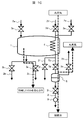
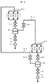
- FIG. 1 is a schematic diagram schematically showing a configuration of a CO 2 recovery device according to Example 1.
- FIG. Using a CO 2 recovery apparatus according to Embodiment 1 is a diagram showing an example of a flow of a capture process to capture CO 2 from CO 2 containing gas.
- Using a CO 2 recovery apparatus according to Embodiment 1 is a diagram showing an example of a flow of the regeneration step of recovering the CO 2 desorbed by heating the CO 2 from the captured CO 2 capturing material.
- Using a CO 2 recovery apparatus according to Embodiment 1 is a diagram showing an example of a flow of the cooling step of cooling the CO 2 capturing material the CO 2 desorbed by heating.
- the structure of the CO 2 recovery apparatus according to Comparative Example is a schematic view schematically showing.
- FIG. I a diagram showing a CO 2 capture unit of the CO 2 recovery apparatus.
- Example 3 is a schematic diagram schematically showing a configuration of a plurality of CO 2 capture unit and the CO 2 recovery apparatus combines one reservoir. It is a diagram showing an operation example of a CO 2 recovery apparatus shown in FIG.
- Example 4 is a diagram showing a configuration example of a CO 2 recovery apparatus used in the regeneration step of another CO 2 recovery apparatus the discharged steam from the reservoir in the regeneration step.
- Example 5 is a schematic view schematically showing the structure of a CO 2 recovery apparatus comprising a reservoir for pooled cooling water discharged from the heat transfer section.
- Example 6 a plurality of CO 2 capturing units are installed, and a part of the cooling water discharged in the cooling process of one CO 2 capturing unit and the condensed water discharged in the regeneration process of the other CO 2 capturing unit.
- Example 7 is a schematic diagram schematically showing the configuration of a CO 2 recovery apparatus installed piping for introducing steam to the capture material container.
- the CO 2 recovery apparatus according to the present invention is a diagram showing an apparatus configuration example in the case of applying the thermal power plant.
- the present inventors have made intensive studies of the above problems, capturing material container filled with solid CO 2 capture material to remove CO 2 from a gas (CO 2 containing gas) containing CO 2, provided in the capturing material container
- a heat transfer section for heating and cooling the CO 2 capture material connected to the capture material container, a first pipe for introducing a CO 2 -containing gas into the capture material container, connected to the capture material container, second pipe for discharging the gas from which CO 2 has been removed from the CO 2 containing gas from the trapping material container is connected to the capturing material container, the heat transfer of CO 2 from the CO 2 capturing material to desorb third pipe for introducing steam into parts, being connected to said capturing material container, a fourth pipe for discharging a gas containing CO 2 desorbed from the CO 2 capturing material from the capturing material container, the capturing material container
- the cooling water is connected to the heat transfer section.
- a CO 2 capture unit including a seventh pipe for discharging cooling water from the heat transfer section, and a first valve that is provided in the sixth pipe and controls the flow rate of the condensed water flowing through the sixth pipe.
- a storage container that is connected to the sixth pipe and stores the condensed water discharged from the heat transfer section; an eighth pipe that is connected to the storage container and discharges the condensed water from the storage container; A ninth valve connected to the storage container for discharging water vapor from the storage container; a second valve provided in the eighth pipe for controlling the flow rate of condensed water flowing through the eighth pipe; The eighth pipe is provided on the downstream side of the second valve of the eighth pipe.
- the CO 2 recovery apparatus and a flow meter for measuring the flow rate of the condensed water that flows were considered possible to reduce the variation in the flow rate of the condensed water.
- the amount of condensed water generated during the introduction of steam into the heat transfer section for heating the CO 2 capturing material varies with the temperature of the CO 2 capturing material.
- the amount of condensed water discharged is controlled in order to control the amount of condensed water that is stored and discharged in the storage container even if the amount of generated condensed water varies over time. It is also possible to reduce the time change of the water and to make the discharge amount of the condensed water constant.
- the CO 2 capturing material used in the CO 2 recovery apparatus may be any substance, but for example, an alkali metal oxide or carbonate such as Na or K, or an alkaline earth metal such as Mg or Ca. Oxides or carbonates of the above, oxides or carbonates of rare earth metals such as Y and Ce, Zr oxide, and oxides of Si and Al can be used.
- Ce, La, Pr, oxides of at least one rare earth element selected from the group consisting of Nd, and Gd are often trapped amount of CO 2, CO at 300 ° C. or less of the low temperature 2 Since it can be desorbed, it has preferable characteristics as a CO 2 capturing material.
- Examples of the method of operating a CO 2 recovery apparatus comprises a capture step of capturing CO 2 from CO 2 containing gas by introducing CO 2 containing gas to the capturing material container, by introducing steam into the heat transfer section a regeneration step for desorbing recovering CO 2 by heating the CO 2 capturing material, wherein one cycle of three steps of cooling step of cooling the CO 2 capturing material by introducing cooling water into the heat transfer section, the cycle A method of repeatedly collecting CO 2 can be mentioned.
- FIG. 1A is a schematic diagram schematically showing the configuration of a CO 2 recovery apparatus according to the present embodiment. With the configuration shown in FIG. 1A, it is possible to reduce the time change in the flow rate of the condensed water discharged from the CO 2 recovery device.
- the CO 2 recovery apparatus according to this embodiment includes a trapping material container 1, a pipe 2a, a pipe 2b, a pipe 2c, a heat transfer unit 4, a pipe 2d, a pipe 2e, a pipe 2f, a storage container 5, a pipe 2g, a pipe 2h, and a pipe 2i. And valves 3a to 3i. Further, the pipe 2i includes a flow meter 9 on the downstream side of the valve 3i.
- the pipes 2 a to 2 f are connected to the capture material container 1, the pipe 2 g is connected to the capture material container 1 and the storage container 5, and the pipes 2 h and 2 i are connected to the storage container 5.
- the valves 3a to 3i are provided in the pipes 2a to 2i, respectively.
- the capture material container 1 is filled with a solid CO 2 capture material (not shown) that removes CO 2 from the CO 2 -containing gas.
- the pipe 2 a introduces the CO 2 -containing gas into the capture material container 1.
- the pipe 2b discharges the gas from which the CO 2 has been removed from the CO 2 -containing gas from the trapping material container 1.
- the pipe 2 c discharges the gas containing CO 2 desorbed from the CO 2 capturing material from the capturing material container 1.
- the heat transfer unit 4 is provided in the capturing material container 1 and heats and cools the CO 2 capturing material by heat exchange.
- the structure of the heat transfer unit 4 is, for example, a structure having piping that allows water vapor and cooling water to flow around the CO 2 capturing material.
- the pipe 2d introduces water vapor into the heat transfer unit 4 in order to desorb CO 2 from the CO 2 capturing material.
- the pipe 2 e introduces cooling water into the heat transfer unit 4.
- the pipe 2 f discharges cooling water from the heat transfer unit 4.
- the storage container 5 stores the condensed water discharged from the heat transfer unit 4.
- the pipe 2 g connects the capture material container 1 and the storage container 5, discharges condensed water generated when water vapor is introduced into the heat transfer unit 4 from the heat transfer unit 4, and introduces it into the storage container 5.
- the pipe 2 h discharges water vapor from the storage container 5.
- the pipe 2 i discharges condensed water from the storage container 5.
- the valve 3a controls the flow rate of the CO 2 containing gas flowing through the pipe 2a.
- the valve 3b controls the flow rate of the gas from which CO 2 flowing through the pipe 2b is removed.
- the valve 3c controls the flow rate of the gas containing desorbed CO 2 flowing through the pipe 2c.
- the valve 3d controls the flow rate of water vapor flowing through the pipe 2d.
- the valve 3e controls the flow rate of the cooling water flowing through the pipe 2e.
- the valve 3f controls the flow rate of the cooling water flowing through the pipe 2f.
- the valve 3g controls the flow rate of the condensed water flowing through the pipe 2g.
- the valve 3h controls the flow rate of water vapor flowing through the pipe 2h.
- the valve 3i controls the flow rate of the condensed water flowing through the pipe 2i.
- the valve 3h also controls the pressure of water vapor in the storage container 5.
- the flow meter 9 measures the flow rate of the condensed water flowing through the pipe 2i.
- Capture material container 1 pipe 2a, pipe 2b, pipe 2c, heat transfer section 4, pipe 2d, pipe 2e, pipe 2f, pipe 2g, valve 3a, valve 3b, valve 3c, valve 3d, valve 3e, valve 3f, and The component consisting of the valve 3g is referred to as a CO 2 capture unit.
- FIG. 1B is a diagram illustrating an example of a flow of a capturing step of capturing CO 2 from a CO 2 -containing gas using the CO 2 recovery apparatus according to the present embodiment.
- the valves 3a and 3b are opened, and the valves 3c, 3d, 3e, 3f, 3g, 3h and 3i are closed.
- the CO 2 -containing gas is introduced into the capturing material container 1 through the pipe 2a.
- CO 2 containing gas is contacted with CO 2 capturing material of capturing material container 1, CO 2 capture material by capturing CO 2, CO 2 is removed.
- the gas from which CO 2 has been removed (CO 2 removal gas) is discharged from the trapping material container 1 through the pipe 2b.
- FIG. 1C is a diagram illustrating an example of a flow of a regeneration process in which CO 2 is desorbed and recovered from a CO 2 capturing material that has captured CO 2 by using the CO 2 recovery apparatus according to the present embodiment.
- the valves 3c, 3d, 3g, 3h and 3i are opened, and the valves 3a, 3b, 3e and 3f are closed.
- Water vapor is introduced into the heat transfer section 4 through the pipe 2d. After the water vapor passes through the heat transfer section 4, a part of it becomes condensed water and is temporarily stored in the storage container 5, and the rest is discharged through the pipe 2 h.
- the flow rate is controlled by the valve 3 i to flow through the pipe 2 i and is discharged from the storage container 5.
- the opening of the valve 3i is changed according to the measurement value of the flow meter 9 provided in the pipe 2i, and the valve 3i performs control to make the flow rate of the condensed water flowing through the pipe 2i constant.
- the heat transfer section 4 is heated when water vapor is introduced, and heats the CO 2 capturing material by heat exchange.
- the CO 2 capturing material desorbs the captured CO 2 when heated.
- the desorbed gas containing CO 2 is discharged from the capture material container 1 through the pipe 2c and collected.
- FIG. 1D using the CO 2 recovery apparatus according to this embodiment, the CO 2 capturing material the CO 2 desorbed by heating, is a diagram illustrating an example of a flow of the cooling step of cooling to CO 2 capture possible temperature .
- the valves 3e and 3f are opened, and the valves 3a, 3b, 3c, 3d, 3g, 3h and 3i are closed.
- Cooling water is introduced into the heat transfer section 4 through the pipe 2e.
- the heat transfer unit 4 is cooled when the cooling water is introduced, and cools the CO 2 capturing material by heat exchange.
- the cooling water introduced into the heat transfer unit 4 is discharged from the heat transfer unit 4 through the pipe 2f.
- the cooling water is introduced into the heat transfer section 4 until the CO 2 capturing material is cooled to a temperature at which CO 2 can be captured.
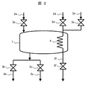
- FIG. 2 is a schematic view schematically showing the configuration of a CO 2 recovery device according to a comparative example.
- the CO 2 recovery apparatus according to the comparative example is a CO 2 recovery apparatus in which the storage container 5, the pipes 2g, 2h, and 2i, and the valves 3g, 3h, and 3i are omitted from the CO 2 recovery apparatus of Example 1 shown in FIG. 1A. is there.
- the water vapor introduced into the heat transfer unit 4 is condensed through the heat transfer unit 4 and then discharged through the pipe 2f.
- Figure 3 is a CO 2 recovery apparatus according to comparative example CO 2 recovery apparatus according to Example 1, a diagram comparing the emission of the condensed water in the regeneration step.
- the heat transfer section 4 is heated by the steam and the CO 2 capturing material is also heated, but as the temperature of the CO 2 capturing material rises, the condensation rate of the steam becomes slow.
- the condensed water is temporarily stored in the storage container 5 and then discharged from the storage container 5 with the flow rate controlled by the valve 3 i and the flow meter 9. Therefore, in the CO 2 recovery apparatus according to the first embodiment, as shown in FIG. 3, it is possible to reduce the temporal change in the amount of condensed water discharged and to make the amount of condensed water discharged constant.
- the generated condensed water is discharged as it is without being stored, so the amount of condensed water discharged decreases as the regeneration process proceeds and does not become constant.
- FIG. 4 is a diagram illustrating an example of a method for operating the CO 2 recovery apparatus according to the first embodiment.
- the capture process, the regeneration process, and the cooling process described above are defined as one cycle, and CO 2 can be continuously recovered by repeating this cycle.
- Example 1 For recovering CO 2, but may be used only one CO 2 recovery apparatus shown in Example 1, may be used a plurality of CO 2 recovery apparatus.
- a method for operating the CO 2 recovery apparatus when CO 2 is recovered using a plurality of CO 2 recovery apparatuses will be described.
- each CO 2 recovery device is referred to as recovery devices A, B, and C.
- the collection devices A, B, and C are set so that the execution times of the capture process, the regeneration process, and the cooling process are the same between the collection apparatuses and between the processes.
- the steps of the recovery devices A, B, and C are switched by switching the opening and closing of the valves as described in the first embodiment.
- Table 1 shows an example of an operation method for switching the capture process, the regeneration process, and the cooling process of the recovery apparatuses A, B, and C.
- the valve opening / closing procedure in each step is the same as that in the first embodiment, and the recovery devices A, B, and C repeat the capturing step, the regeneration step, and the cooling step.
- the recovery device A when the recovery device A is executing the capturing step, the recovery device B executes the regeneration step, and the recovery device C executes the cooling step.
- the recovery apparatus A when the recovery apparatus A is executing the regeneration process, the recovery apparatus B performs the cooling process, the recovery apparatus C executes the capture process, and when the recovery apparatus A is executing the cooling process, the recovery apparatus B captures The recovery device C performs the process and the regeneration process.
- each CO 2 capture device is operated such that at least one other CO 2 capture device performs the cooling step.
- At least one CO 2 recovery apparatus executes the capturing step, so that CO 2 can be continuously recovered.
- the process of introducing water vapor into the heat transfer section 4 of the CO 2 recovery apparatus is only the regeneration process. For this reason, when a plurality of CO 2 recovery apparatuses are used as in the second embodiment, there is also a capturing material container 1 in which water vapor is not introduced into the heat transfer section 4 in a certain time. Therefore, it is not always necessary to install one storage container 5 for one capture material container 1.
- one storage container 5 is installed for three capture material containers 1, and a valve 3 g (for example, see FIG. 1A) is provided between the heat transfer section 4 and the storage container 5 of each capture material container 1.
- an example of a CO 2 recovery device in which one storage container 5 is installed for a plurality of capture material containers 1 is shown.
- an example of a CO 2 recovery apparatus is one reservoir 5 for the three capturing material container 1 is installed.
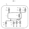
- FIG. 5 is a diagram illustrating the CO 2 capturing unit 6 of the CO 2 recovery apparatus (FIG. 1A) illustrated in the first embodiment.
- the CO 2 capturing unit 6 includes the capturing material container 1, the heat transfer section 4, the pipes 2a to 2g, and the valves 3a to 3g. That is, the CO 2 capturing unit 6 is an apparatus element in which the storage container 5, the pipe 2i, the pipe 2h, the valve 3i, and the valve 3h are omitted from the CO 2 recovery apparatus (FIG. 1A) of the first embodiment.
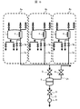
- FIG. 6 is a schematic view schematically showing a configuration of a CO 2 recovery device in which the three CO 2 capturing units 6 (6a, 6b, 6c) shown in FIG. 5 and one storage container 5 are combined.
- the CO 2 recovery apparatus according to the present embodiment includes three CO 2 capturing units 6a, 6b, and 6c, and the piping 2g of each CO 2 capturing unit joins at one point.
- valve 3j the storage container 5 for storing the condensed water
- the pipe 2i for discharging the condensed water from the storage container 5
- the valve 3i for controlling the flow rate of the condensed water in the pipe 2i
- the storage container 5 A pipe 2h for discharging water vapor and a valve 3h for controlling the flow rate of water vapor in the pipe 2h are further provided.
- the storage container 5 stores the condensed water from the CO 2 capturing units 6a, 6b, and 6c. By switching the opening and closing of the respective valves 3g of the CO 2 capturing units 6a, 6b, and 6c, the CO 2 capturing unit that discharges condensed water to the storage container 5 can be switched.
- FIG. 7 is a diagram illustrating an operation example of the CO 2 recovery device illustrated in FIG. 6.
- the CO 2 capturing unit 6a performs the capturing process shown in FIG. 1B
- the CO 2 capturing unit 6b performs the regeneration process illustrated in FIG. 1C
- the CO 2 capturing unit 6c performs the cooling process illustrated in FIG. 1D.
- the CO 2 capture units 6a, 6b, and 6c are set so that the execution times of the capture process, the regeneration process, and the cooling process are the same between the CO 2 capture units and between the processes as in the second embodiment. To do.
- the opening and closing of the valve is the same as that of the first embodiment except that the valves 3g, 3j, and 3h are opened regardless of the steps of the CO 2 capturing units 6a, 6b, and 6c.
- the condensed water stored in the storage container 5 is discharged from the storage container 5 with the flow rate controlled by the valve 3 i and the flow meter 9.
- the capture process, the regeneration process, and the cooling process are switched by opening and closing the valve as described in the first embodiment, and these three processes are repeated as one cycle so that CO 2 is continuously generated. Can be recovered. Further, similarly to the second embodiment, it is possible to reduce temporal changes in the discharge amount of condensed water, the flow rate of water vapor, and the flow rate of cooling water, and it is possible to further suppress fluctuations in the load on the boiler. Moreover, since the number of installation of the storage container 5 can be reduced, cost can be reduced.
- the flow rate of the water vapor introduced into the heat transfer unit 4 is not particularly specified, it is conceivable that the pressure of the water vapor in the heat transfer unit 4 significantly decreases when the water vapor condensation rate is faster than the water flow rate. In this case, since the temperature of the generated condensed water changes greatly, returning the condensed water to the boiler is not preferable because the load on the boiler varies greatly. In order to reduce the temporal change in the temperature of the condensed water, it is preferable that the minimum flow rate of the water vapor is set to a flow rate that does not condense all the water vapor.
- the CO 2 recovery device since the water vapor that has not been condensed flows into the storage container 5, this water vapor needs to be discharged. Since the water vapor discharged from the storage container 5 has heat of condensation, it is preferable to use it because the energy loss is large if it is discharged unused. There are various methods of using the water vapor discharged from the storage container 5, and for example, a method of using this water vapor for another CO 2 recovery device is conceivable.
- the regeneration step in the first half of the regeneration step is lower the temperature of the CO 2 capturing material is, but many condensation of water vapor in the heat transfer section 4, the temperature of the CO 2 capturing material becomes high in the second half of the regeneration step, the heat transfer The amount of water vapor condensation in the section 4 is reduced. Therefore, if the flow rate of water vapor is constant over time, the amount of water vapor discharged from the storage container 5 decreases as the time of the regeneration process advances and the amount of condensation in the heat transfer section 4 decreases. Become.
- FIG. 8 is a diagram showing a configuration example of a CO 2 recovery device obtained based on the above knowledge and using the water vapor discharged from the storage container 5 in the regeneration step in the regeneration step of another CO 2 recovery device. is there.
- the CO 2 recovery apparatus according to this embodiment is a CO 2 recovery apparatus in which two CO 2 recovery apparatuses shown in FIG.
- CO 2 capture unit 6a ⁇ 6c, reservoir 5a, pipe 2i, pipe 2h-1, the valve 3j-1, and the CO 2 recovery apparatus comprising a valve 3i, and the valve 3h-1
- CO 2 capture unit 6d ⁇ 6f
- reservoir 5b piping 2i, pipe 2h-2, the valve 3j-2
- CO 2 recovering apparatus CO 2 recovery system and is connected to a valve 3i, and the valve 3h-2.
- the CO 2 capturing units 6d to 6f correspond to the CO 2 capturing units 6a to 6c in FIG. 6,
- the pipe 2h-1 and the pipe 2h-2 correspond to the pipe 2h in FIG. 6, and the valves 3j-1 and 3j-2 Corresponds to the valve 3j in FIG. 6, and the valves 3h-1 and 3h-2 correspond to the valve 3h in FIG.
- a pipe 2h-2 for discharging water vapor from the storage container 5b and a pipe 2d-1 for branching from the pipe 2h-2 to introduce water vapor into the CO 2 capturing units 6a to 6c are provided.
- Pipe 2d-2 introduces steam into each heat transfer section 4 of CO 2 capture units 6d-6f
- pipe 2d-1 introduces steam into each heat transfer section 4 of CO 2 capture units 6a-6c.
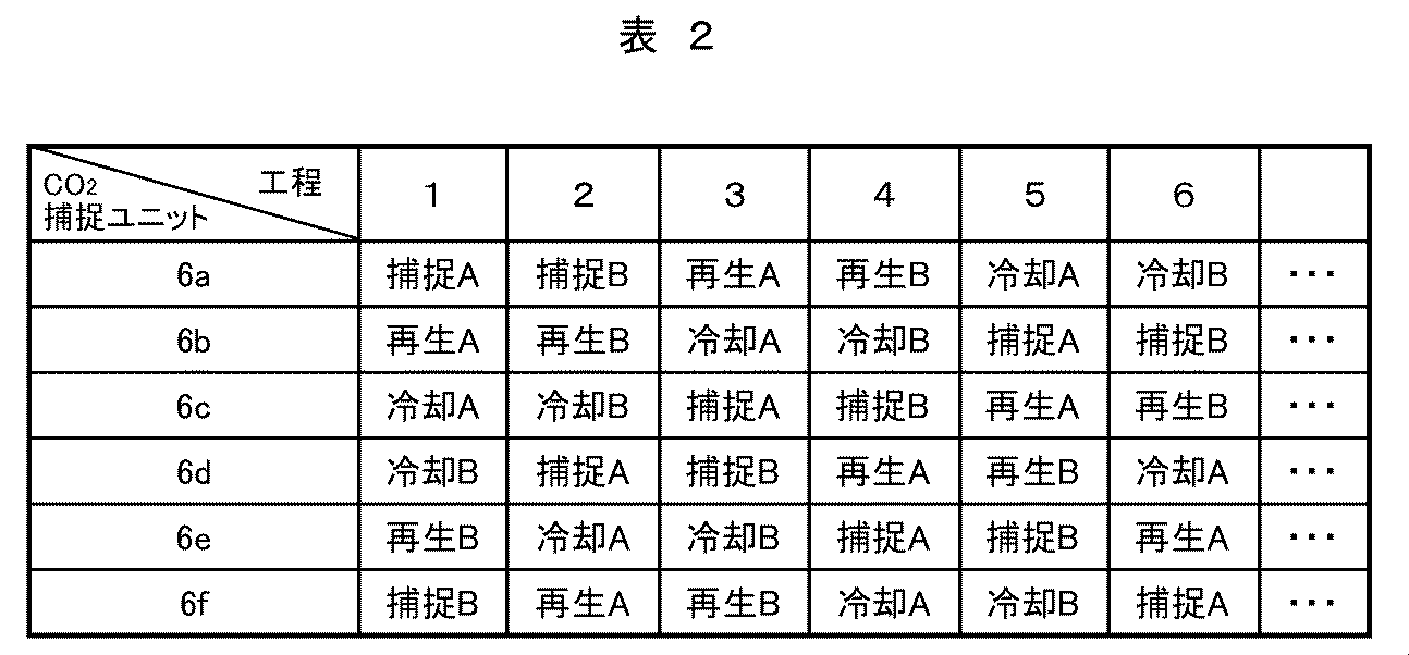
- Table 2 shows an example of the operation method of the CO 2 recovery apparatus according to this embodiment.
- the CO 2 capturing units 6a to 6f have the same execution time for the capturing process, the regeneration process, and the cooling process between the CO 2 capturing units 6a to 6f and between the processes.
- Each process is divided into a first half process and a second half process having the same execution time.
- the first half of the regeneration process the amount of water vapor condensed in the heat transfer section 4 is large, and the amount of water vapor discharged from the storage container 5 is small.
- the second half of the regeneration process the amount of water vapor condensed in the heat transfer section 4 is small, and the amount of water vapor discharged from the storage container 5 is large.
- the letter “A” is attached to the first half of each process
- the letter “B” is attached to the second half.
- the first half and the second half of each process are regarded as one process.
- the first half of the regeneration process (“Regeneration A” in Table 2) is one process
- the second half of the regeneration process (“Regeneration B” in Table 2) is one process.
- the CO 2 capture units 6a to 6f are arranged in the order of “capture A”, “capture B”, “regeneration A”, “regeneration B”, “cooling A”, and “cooling B”. Repeat the process.
- the CO 2 capture unit 6a is 2 steps
- the CO 2 capture unit 6c is 4 steps
- the CO 2 capture unit 6d is 5 steps
- the CO 2 capture unit 6e is 3 steps
- Unit 6f is delayed by one step.
- one CO 2 capture unit of the CO 2 capture unit 6a ⁇ 6c, one CO 2 capture unit of the CO 2 capture unit 6d ⁇ 6f has carried out the regeneration step.
- one CO 2 capture unit always performs the first half of the regeneration process (regeneration A) and the other one performs the second half of the regeneration process (regeneration B).
- emitted from the storage container 5 in the second half (regeneration B) of a regeneration process can be continuously used for the first half (regeneration A) of a regeneration process.
- the amount of water vapor used in the regeneration process can be reduced, and time fluctuations in the amount of water vapor used can also be reduced.
- the explanation CO 2 recovery apparatus comprising a container for storing the cooling water discharged from the heat transfer section 4.
- FIG. 9 is a schematic view schematically showing a configuration of a CO 2 recovery device including a storage container 7 that stores the cooling water discharged from the heat transfer section 4.
- CO 2 recovery apparatus of this embodiment the CO 2 recovery apparatus in Example 1 (see FIG. 1A), the storage container 7 connected to the pipe 2f, a pipe 2p is connected to the storage container 7, the pipe 2p It further includes a valve 3p for controlling the flow rate.
- the storage container 7 is introduced from the pipe 2 e to the heat transfer unit 4, cools the CO 2 capturing material, and stores the cooling water discharged from the heat transfer unit 4.
- the cooling water stored in the storage container 7 is averaged in temperature and discharged from the pipe 2p when the valve 3p is opened at a predetermined constant temperature.
- the CO 2 recovery apparatus discharges the cooling water whose temperature is averaged in the storage container 7, it is possible to reduce the time change of the temperature of the cooling water to be discharged, and to supply a constant temperature of cooling water to the feed water heater. Can be supplied.
- the cooling water discharged in the cooling process is discharged in the regeneration process.
- a plurality of CO 2 capture units 6 see FIG. 5) of the CO 2 recovery apparatus described in the third embodiment are installed, and one arbitrary CO 2 capture is performed.
- a part of the cooling water discharged in the unit cooling process is mixed with a part of the condensed water discharged in the regeneration process of the other CO 2 capturing unit.
- Figure 10 is a CO 2 capture unit 6 of the CO 2 recovery apparatus and a plurality installed, a part of the cooling water discharged by the cooling process of any one of CO 2 capture unit, other CO 2 capture unit regeneration step in a schematic view schematically showing the structure of a CO 2 recovery device for mixing a portion of the condensed water discharged.
- Example 1 in the CO 2 recovery apparatus shown in FIG. 1A are connected two, two CO 2 capture unit (CO 2 capture unit 6 g, 6h) comprises shows the CO 2 recovery system Yes.
- the CO 2 recovery apparatus shown in FIG. 10 has a pipe 2i-1 for discharging condensed water from the storage container 5 connected to the CO 2 capturing unit 6g, and a pipe for extracting a part of the condensed water from the pipe 2i-1.
- Valves 3k-1 and 3k-2 and piping 2l-1 And 2l-2 control valves 3l-1 and 3l-2 for controlling the flow rate of cooling water, respectively, the pipe 2k-1 and the pipe 2l-2 are connected, and the pipe 2l-1 and the pipe 2k-2 are connected. It is connected.
- a part of the cooling water flowing through the pipe 2f-1 passes through the pipe 21-1, and is extracted from the pipe 2i-2 and mixed with the condensed water flowing through the pipe 2k-2.
- a part of the cooling water flowing through the pipe 2f-2 passes through the pipe 21-2 and is extracted from the pipe 2i-1 and mixed with the condensed water flowing through the pipe 2k-1.
- a part of the cooling water discharged in one of the two CO 2 capturing units 6g and 6h and the other regeneration process are discharged. Can be mixed with some of the condensed water.
- the cooling discharged from the CO 2 recovery apparatus is controlled by controlling the opening degree of the valves 3l-1 and 3k-2 and the opening degree of the valves 3l-2 and 3k-1.
- the temperature change of water can be reduced. For example, when the temperature of the cooling water flowing through the pipe 21-1 is low, by controlling the opening degree of the valve 3 k-2 and increasing the flow rate of the condensed water flowing through the pipe 2 k-2, the CO 2 recovery device The temperature change of the discharged cooling water can be reduced.
- the gas other than CO 2 introduced into the trapping material container 1 is preferably easily separable from CO 2 due to temperature change or the like, and an example of such a gas is water vapor. Below, the example which introduce
- FIG. 11 is a schematic view schematically showing the configuration of a CO 2 recovery device in which a pipe for introducing water vapor is installed in the trapping material container 1.
- a pipe for introducing water vapor is installed in the CO 2 recovery apparatus of Example 1 (see FIG. 1A).
- the CO 2 recovery apparatus according to the present embodiment controls the flow rate of water vapor flowing through the pipe 2m and the pipe 2m through which the water vapor flows through the capturing material container 1.
- valve 3m The valve 3m, the condenser 8 connected to the pipe 2c and condensing water vapor in the gas flowing through the pipe 2c, the pipe 2n for discharging condensed water from the condenser 8, and the flow rate of the condensed water flowing through the pipe 2n are controlled.
- a valve 3n, a pipe 2o for discharging the gas containing desorbed CO 2 from the condenser 8, and a valve 3o for controlling the flow rate of the gas flowing through the pipe 2o are provided.
- the CO 2 recovery apparatus in the regeneration process, when the partial pressure of CO 2 increases in the capture material container 1, water vapor is introduced into the capture material container 1 through the pipe 2m, and the partial pressure of CO 2 is obtained. Can be lowered. Therefore, even if increasing the partial pressure of CO 2 in the capturing material vessel 1, by reducing the partial pressure of CO 2, can facilitate the desorption of CO 2 from the CO 2 capturing material.
- the water vapor introduced into the trapping material container 1 is discharged from the trapping material container 1, introduced into the condenser 8, condensed, and discharged from the pipe 2 n as condensed water.
- the CO 2 desorbed from the CO 2 capturing material is discharged from the capturing material container 1 and discharged through the condenser 8 and the pipe 2o.
- the CO 2 recovery apparatus according to the present invention is applicable to any plant or system. it can.
- the CO 2 recovery device according to the present invention is applied to a thermal power plant.
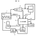
- FIG. 12 is a diagram showing an apparatus configuration example when the CO 2 recovery apparatus according to the present invention is applied to a thermal power plant.
- the CO 2 recovery apparatus 10 according to the present embodiment is the one shown in the first embodiment (see FIG. 1A), and recovers CO 2 generated in the thermal power plant.
- the thermal power plant includes a combustion facility, a steam turbine 12, a condenser 13, a feed water heater A14, a feed water heater B15, an exhaust facility 16, and a CO 2 recovery device 10.
- a case where the combustion facility 11 is a boiler 11 is taken as an example.
- the boiler 11 which is the combustion facility 11 generates CO 2 -containing gas as combustion exhaust gas when burning fuel, and vaporizes water with combustion heat to generate water vapor.
- the steam turbine 12 generates power using this water vapor. A part of the steam used by the steam turbine 12 is introduced into the CO 2 recovery device 10, and the rest is condensed by the condenser 13 and used as cooling water.
- the pipe 2 a for introducing the CO 2 -containing gas into the CO 2 recovery device 10 is connected to the boiler 11 and introduces the combustion exhaust gas from the boiler 11 into the CO 2 recovery device 10.
- a pipe 2 d for introducing water vapor into the CO 2 recovery device 10 is connected to the steam turbine 12, and introduces water vapor from the steam turbine 12 into the CO 2 recovery device 10.
- a pipe 2 e that introduces cooling water into the CO 2 recovery apparatus 10 is connected to the condenser 13, and introduces cooling water from the condenser 13 into the CO 2 recovery apparatus 10.
- a pipe 2b for discharging the gas from which CO 2 has been removed from the CO 2 recovery apparatus 10 is connected to an exhaust facility 16.
- a pipe 2f for discharging cooling water from the CO 2 recovery apparatus 10 is connected to the feed water heater A14.
- a pipe 2i for discharging condensed water from the CO 2 recovery apparatus 10 is connected to a feed water heater B15.
- a pipe 2 h that discharges water vapor from the CO 2 recovery device 10 introduces water vapor into the condenser 13.
- part or all of the combustion exhaust gas discharged from the boiler 11 flows through the pipe 2a of the CO 2 recovery apparatus 10, and after CO 2 is removed, flows through the pipe 2b to the exhaust facility 16.
- the regeneration process a part of the water vapor is extracted from the steam turbine 12 and flows into the pipe 2d.
- the water vapor flowing through the pipe 2d heats the CO 2 capturing material of the CO 2 recovery device 10 to desorb CO 2 from the CO 2 capturing material.
- the gas containing CO 2 desorbed from the CO 2 capturing material flows through the pipe 2c and is recovered.
- the CO 2 is pressurized and recovered as liquefied CO 2 .
- the condensed water generated by the condensation of water vapor in the regeneration process flows through the pipe 2i and is sent to the condensed water side of the feed water heater B15.
- the water vapor that has not been condensed in the CO 2 recovery device 10 is sent to the steam turbine 12 or the condenser 13. In the example shown in FIG. 12, the water vapor flows through the pipe 2 h and is sent to the condenser 13.
- the cooling water discharged in the cooling process flows through the pipe 2f and is sent to the feed water heater A14.
- the cooling water sent to the feed water heater A14 is sent to the feed water heater B15.
- the water (condensed water and cooling water) sent to the feed water heater B15 is supplied to the boiler 11. And condensed water discharged from the CO 2 recovering apparatus 10 in the regeneration step, the cooling water discharged from the CO 2 recovering apparatus 10 in the cooling step, since the direction of the condensed water discharged in the regeneration step is a high temperature, water It is better that the heater B15 has a higher temperature setting than the feed water heater A14.
Landscapes
- Chemical & Material Sciences (AREA)
- Engineering & Computer Science (AREA)
- Analytical Chemistry (AREA)
- General Chemical & Material Sciences (AREA)
- Oil, Petroleum & Natural Gas (AREA)
- Chemical Kinetics & Catalysis (AREA)
- Carbon And Carbon Compounds (AREA)
- Treating Waste Gases (AREA)
- Gas Separation By Absorption (AREA)
- Solid-Sorbent Or Filter-Aiding Compositions (AREA)
Abstract
Description
図2は、比較例によるCO2回収装置の構成を模式的に示す概略図である。比較例によるCO2回収装置は、図1Aに示した実施例1のCO2回収装置から、貯留容器5、配管2g、2h及び2iと、弁3g、3h及び3iを省いたCO2回収装置である。比較例によるCO2回収装置は、再生工程では、伝熱部4に導入された水蒸気は、伝熱部4を通って凝縮水となった後、配管2fを通って排出される。
図3は、実施例1によるCO2回収装置と比較例によるCO2回収装置について、再生工程での凝縮水の排出量を比べた図である。再生工程では、水蒸気により伝熱部4が加熱されてCO2捕捉材も加熱されるが、CO2捕捉材の温度上昇に伴って水蒸気の凝縮速度が遅くなる。

Claims (15)
- CO2含有ガスからCO2を除去する固体のCO2捕捉材を充填した捕捉材容器、
前記捕捉材容器に設けられ、前記CO2捕捉材を加熱及び冷却する伝熱部、
前記捕捉材容器に接続され、前記捕捉材容器にCO2含有ガスを導入する第1の配管、
前記捕捉材容器に接続され、前記CO2含有ガスからCO2が除去されたガスを前記捕捉材容器から排出する第2の配管、
前記捕捉材容器に接続され、前記CO2捕捉材からCO2を脱離させるために前記伝熱部に水蒸気を導入する第3の配管、
前記捕捉材容器に接続され、前記CO2捕捉材から脱離したCO2を含むガスを前記捕捉材容器から排出する第4の配管、
前記捕捉材容器に接続され、前記伝熱部に冷却水を導入する第5の配管、
前記捕捉材容器に接続され、前記伝熱部に水蒸気を導入した際に発生する凝縮水を前記伝熱部から排出する第6の配管、
前記捕捉材容器に接続され、前記伝熱部から冷却水を排出する第7の配管、及び
前記第6の配管に設けられ、前記第6の配管に流れる凝縮水の流量を制御する第1の弁を備えるCO2捕捉ユニットと、
前記第6の配管に接続され、前記伝熱部から排出された凝縮水を貯留する貯留容器と、
前記貯留容器に接続され、前記貯留容器から凝縮水を排出する第8の配管と、
前記貯留容器に接続され、前記貯留容器から水蒸気を排出する第9の配管と、
前記第8の配管に設けられ、第8の配管に流れる凝縮水の流量を制御する第2の弁と、
前記第8の配管の前記第2の弁の下流側に設けられ、前記第8の配管を流れる凝縮水の流量を計測する流量計と、を備えることを特徴とするCO2回収装置。 - 前記CO2捕捉ユニットを複数備える請求項1記載のCO2回収装置。
- 前記CO2捕捉ユニットを複数備え、
前記貯留容器は、複数の前記CO2捕捉ユニットの前記第6の配管が接続され、複数の前記CO2捕捉ユニットの前記伝熱部から排出された凝縮水を貯留する請求項1記載のCO2回収装置。 - 請求項2または3記載のCO2回収装置を2つ備え、
少なくとも一方の前記CO2回収装置の前記第9の配管は、他方の前記CO2回収装置のそれぞれの前記第3の配管に接続され、少なくとも前記一方のCO2回収装置の前記貯留容器から排出された水蒸気が、前記他方のCO2回収装置のそれぞれの前記捕捉材容器の前記伝熱部に導入される請求項2または3記載のCO2回収装置。 - 前記第7の配管に接続され、前記伝熱部から排出された冷却水を貯留する貯留容器をさらに備える請求項1記載のCO2回収装置。
- 請求項1記載のCO2回収装置を2つ備え、
少なくとも一方の前記CO2回収装置の第8の配管は、他方の前記CO2回収装置の第7の配管と接続され、少なくとも前記一方のCO2回収装置の前記貯留容器から排出された凝縮水と、前記他方のCO2回収装置の前記伝熱部から排出された冷却水とが混合される請求項1記載のCO2回収装置。 - 前記捕捉材容器に接続され、前記捕捉材容器に水蒸気を導入する第10の配管と、
前記第4の配管に接続され、前記捕捉材容器から排出されたガス中の水蒸気を凝縮させる凝縮器と、をさらに備える請求項1記載のCO2回収装置。 - 前記第1の配管が導入する前記CO2含有ガスは、燃焼設備の燃焼排ガスである請求項1記載のCO2回収装置。
- 前記第3の配管が導入する前記水蒸気は、燃焼設備で水を気化させて発生した水蒸気である請求項1記載のCO2回収装置。
- 前記第5の配管が導入する前記冷却水は、水蒸気を復水器で凝縮した水である請求項1記載のCO2回収装置。
- 前記第7の配管が排出した冷却水と、前記第8の配管が排出した凝縮水は、燃焼設備に供給される請求項1記載のCO2回収装置。
- 前記CO2捕捉材は、Ce、La、Pr、Nd、及びGdからなる群から選ばれた少なくとも1つの元素の酸化物を含む請求項1記載のCO2回収装置。
- CO2含有ガスを前記捕捉材容器に導入することで、前記CO2捕捉材がCO2を捕捉し、前記CO2含有ガスからCO2を除去する捕捉工程と、
前記伝熱部に水蒸気を導入して前記CO2捕捉材を加熱することで、前記CO2捕捉材からCO2を脱離させる再生工程と、
前記伝熱部に冷却水を導入して前記CO2捕捉材を冷却する冷却工程とを有し、
前記捕捉工程、前記再生工程、及び前記冷却工程を繰り返すことを特徴とする請求項1記載のCO2回収装置の運転方法。 - 請求項1記載のCO2回収装置を3つ以上備え、
少なくとも1つの前記CO2回収装置が前記捕捉工程を実行しているとき、他の少なくとも1つの前記CO2回収装置が前記再生工程を実行し、さらに他の少なくとも1つの前記CO2回収装置が前記冷却工程を実行する請求項13記載のCO2回収装置の運転方法。 - 前記捕捉工程、前記再生工程、及び前記冷却工程の実行時間が互いに同じである請求項14記載のCO2回収装置の運転方法。
Priority Applications (3)
| Application Number | Priority Date | Filing Date | Title |
|---|---|---|---|
| JP2014551795A JP5897734B2 (ja) | 2012-12-13 | 2012-12-13 | Co2回収装置及びその運転方法 |
| CA2894486A CA2894486C (en) | 2012-12-13 | 2012-12-13 | Co2 recovery system and method for operating same |
| PCT/JP2012/082289 WO2014091590A1 (ja) | 2012-12-13 | 2012-12-13 | Co2回収装置及びその運転方法 |
Applications Claiming Priority (1)
| Application Number | Priority Date | Filing Date | Title |
|---|---|---|---|
| PCT/JP2012/082289 WO2014091590A1 (ja) | 2012-12-13 | 2012-12-13 | Co2回収装置及びその運転方法 |
Publications (1)
| Publication Number | Publication Date |
|---|---|
| WO2014091590A1 true WO2014091590A1 (ja) | 2014-06-19 |
Family
ID=50933911
Family Applications (1)
| Application Number | Title | Priority Date | Filing Date |
|---|---|---|---|
| PCT/JP2012/082289 Ceased WO2014091590A1 (ja) | 2012-12-13 | 2012-12-13 | Co2回収装置及びその運転方法 |
Country Status (3)
| Country | Link |
|---|---|
| JP (1) | JP5897734B2 (ja) |
| CA (1) | CA2894486C (ja) |
| WO (1) | WO2014091590A1 (ja) |
Cited By (2)
| Publication number | Priority date | Publication date | Assignee | Title |
|---|---|---|---|---|
| JP2019034307A (ja) * | 2018-10-01 | 2019-03-07 | 日立化成株式会社 | Co2除去装置 |
| US12168201B1 (en) | 2023-06-05 | 2024-12-17 | Nokia Solutions And Networks Oy | Carbon dioxide capture from ambient air |
Families Citing this family (1)
| Publication number | Priority date | Publication date | Assignee | Title |
|---|---|---|---|---|
| JP6408082B1 (ja) * | 2017-07-11 | 2018-10-17 | 株式会社西部技研 | ガス回収濃縮装置 |
Citations (3)
| Publication number | Priority date | Publication date | Assignee | Title |
|---|---|---|---|---|
| JPS60153919A (ja) * | 1984-01-25 | 1985-08-13 | Hitachi Ltd | 吸着塔の吸着および再生方法 |
| JPH10156127A (ja) * | 1996-11-29 | 1998-06-16 | I H I Plantec:Kk | ベンゼンベーパー回収装置 |
| US20100263534A1 (en) * | 2007-11-08 | 2010-10-21 | The University Of Akron | Amine absorber for carbon dioxide capture and processes for making and using the same |
Family Cites Families (3)
| Publication number | Priority date | Publication date | Assignee | Title |
|---|---|---|---|---|
| US20030037672A1 (en) * | 2001-08-27 | 2003-02-27 | Shivaji Sircar | Rapid thermal swing adsorption |
| US8580018B2 (en) * | 2010-11-12 | 2013-11-12 | Exxonmobil Research And Engineering Company | Recovery of greenhouse gas and pressurization for transport |
| JP5579630B2 (ja) * | 2011-01-12 | 2014-08-27 | 株式会社日立製作所 | 二酸化炭素回収システム |
-
2012
- 2012-12-13 WO PCT/JP2012/082289 patent/WO2014091590A1/ja not_active Ceased
- 2012-12-13 CA CA2894486A patent/CA2894486C/en active Active
- 2012-12-13 JP JP2014551795A patent/JP5897734B2/ja not_active Expired - Fee Related
Patent Citations (3)
| Publication number | Priority date | Publication date | Assignee | Title |
|---|---|---|---|---|
| JPS60153919A (ja) * | 1984-01-25 | 1985-08-13 | Hitachi Ltd | 吸着塔の吸着および再生方法 |
| JPH10156127A (ja) * | 1996-11-29 | 1998-06-16 | I H I Plantec:Kk | ベンゼンベーパー回収装置 |
| US20100263534A1 (en) * | 2007-11-08 | 2010-10-21 | The University Of Akron | Amine absorber for carbon dioxide capture and processes for making and using the same |
Cited By (2)
| Publication number | Priority date | Publication date | Assignee | Title |
|---|---|---|---|---|
| JP2019034307A (ja) * | 2018-10-01 | 2019-03-07 | 日立化成株式会社 | Co2除去装置 |
| US12168201B1 (en) | 2023-06-05 | 2024-12-17 | Nokia Solutions And Networks Oy | Carbon dioxide capture from ambient air |
Also Published As
| Publication number | Publication date |
|---|---|
| CA2894486A1 (en) | 2014-06-19 |
| JP5897734B2 (ja) | 2016-03-30 |
| JPWO2014091590A1 (ja) | 2017-01-05 |
| CA2894486C (en) | 2017-08-01 |
Similar Documents
| Publication | Publication Date | Title |
|---|---|---|
| JP5812694B2 (ja) | 二酸化炭素回収方法および装置 | |
| US8920548B2 (en) | CO2 capture system by chemical absorption | |
| JP5039651B2 (ja) | 排ガス中の二酸化炭素回収システム | |
| JP5864281B2 (ja) | Co2分離回収装置 | |
| KR101709867B1 (ko) | 이산화탄소 포집장치 | |
| EP2722097A1 (en) | Combustion exhaust gas treatment system and combustion exhaust gas treatment method | |
| JP2009543751A (ja) | 太陽熱エネルギーを使用したco2捕捉 | |
| EP2823876B1 (en) | System for chemically absorbing carbon dioxide in combustion exhaust gas | |
| JP6642590B2 (ja) | 二酸化炭素分離回収装置、これを用いた燃焼システム及び火力発電システム並びに二酸化炭素の分離回収方法 | |
| JP2014057941A (ja) | 二酸化炭素分離回収システムおよび二酸化炭素分離回収方法 | |
| JP2011527936A (ja) | 化石燃料発電所設備の排ガスから二酸化炭素を分離するための方法及び装置 | |
| KR101617083B1 (ko) | 휘발성 유기화합물 처리장치 및 방법 | |
| JP2013059727A (ja) | Co2回収装置およびco2回収方法 | |
| EP2740525A1 (en) | Carbon dioxide separation from a gas by temperature swing adsorption using organic adsorbents | |
| JP5897734B2 (ja) | Co2回収装置及びその運転方法 | |
| JP2019069417A (ja) | 排ガスからの二酸化炭素回収方法及び設備 | |
| WO2013114937A1 (ja) | 二酸化炭素回収装置 | |
| US8975464B2 (en) | Heat recovery from sorbent-based CO2 capture | |
| KR101200101B1 (ko) | 수분제거장치를 가지는 이산화탄소 포집 플랜트 | |
| KR20120013588A (ko) | 이산화탄소 회수장치 | |
| JP5579630B2 (ja) | 二酸化炭素回収システム | |
| JP2023108268A (ja) | Co2回収方法およびco2回収装置 | |
| JP5600048B2 (ja) | 溶剤回収装置 | |
| JP2009208037A (ja) | 溶剤の回収装置 | |
| WO2015052727A2 (en) | A multi-compression system and process for capturing carbon dioxide |
Legal Events
| Date | Code | Title | Description |
|---|---|---|---|
| 121 | Ep: the epo has been informed by wipo that ep was designated in this application |
Ref document number: 12889975 Country of ref document: EP Kind code of ref document: A1 |
|
| ENP | Entry into the national phase |
Ref document number: 2014551795 Country of ref document: JP Kind code of ref document: A |
|
| ENP | Entry into the national phase |
Ref document number: 2894486 Country of ref document: CA |
|
| NENP | Non-entry into the national phase |
Ref country code: DE |
|
| 122 | Ep: pct application non-entry in european phase |
Ref document number: 12889975 Country of ref document: EP Kind code of ref document: A1 |