WO2014088271A1 - 다중 셀 협력 통신 시스템에서 신호 송수신하는 방법 및 이를 위한 장치 - Google Patents
다중 셀 협력 통신 시스템에서 신호 송수신하는 방법 및 이를 위한 장치 Download PDFInfo
- Publication number
- WO2014088271A1 WO2014088271A1 PCT/KR2013/011054 KR2013011054W WO2014088271A1 WO 2014088271 A1 WO2014088271 A1 WO 2014088271A1 KR 2013011054 W KR2013011054 W KR 2013011054W WO 2014088271 A1 WO2014088271 A1 WO 2014088271A1
- Authority
- WO
- WIPO (PCT)
- Prior art keywords
- base station
- terminal
- signal
- terminals
- pilot
- Prior art date
- Legal status (The legal status is an assumption and is not a legal conclusion. Google has not performed a legal analysis and makes no representation as to the accuracy of the status listed.)
- Ceased
Links
Classifications
-
- H—ELECTRICITY
- H04—ELECTRIC COMMUNICATION TECHNIQUE
- H04L—TRANSMISSION OF DIGITAL INFORMATION, e.g. TELEGRAPHIC COMMUNICATION
- H04L5/00—Arrangements affording multiple use of the transmission path
- H04L5/003—Arrangements for allocating sub-channels of the transmission path
- H04L5/0058—Allocation criteria
- H04L5/0073—Allocation arrangements that take into account other cell interferences
-
- H—ELECTRICITY
- H04—ELECTRIC COMMUNICATION TECHNIQUE
- H04B—TRANSMISSION
- H04B7/00—Radio transmission systems, i.e. using radiation field
- H04B7/02—Diversity systems; Multi-antenna system, i.e. transmission or reception using multiple antennas
- H04B7/022—Site diversity; Macro-diversity
- H04B7/024—Co-operative use of antennas of several sites, e.g. in co-ordinated multipoint or co-operative multiple-input multiple-output [MIMO] systems
-
- H—ELECTRICITY
- H04—ELECTRIC COMMUNICATION TECHNIQUE
- H04J—MULTIPLEX COMMUNICATION
- H04J11/00—Orthogonal multiplex systems, e.g. using WALSH codes
- H04J11/0023—Interference mitigation or co-ordination
- H04J11/0026—Interference mitigation or co-ordination of multi-user interference
- H04J11/0036—Interference mitigation or co-ordination of multi-user interference at the receiver
-
- H—ELECTRICITY
- H04—ELECTRIC COMMUNICATION TECHNIQUE
- H04J—MULTIPLEX COMMUNICATION
- H04J11/00—Orthogonal multiplex systems, e.g. using WALSH codes
- H04J11/0023—Interference mitigation or co-ordination
- H04J11/005—Interference mitigation or co-ordination of intercell interference
- H04J11/0053—Interference mitigation or co-ordination of intercell interference using co-ordinated multipoint transmission/reception
-
- H—ELECTRICITY
- H04—ELECTRIC COMMUNICATION TECHNIQUE
- H04L—TRANSMISSION OF DIGITAL INFORMATION, e.g. TELEGRAPHIC COMMUNICATION
- H04L5/00—Arrangements affording multiple use of the transmission path
- H04L5/0001—Arrangements for dividing the transmission path
- H04L5/0014—Three-dimensional division
- H04L5/0023—Time-frequency-space
-
- H—ELECTRICITY
- H04—ELECTRIC COMMUNICATION TECHNIQUE
- H04W—WIRELESS COMMUNICATION NETWORKS
- H04W72/00—Local resource management
- H04W72/50—Allocation or scheduling criteria for wireless resources
- H04W72/54—Allocation or scheduling criteria for wireless resources based on quality criteria
-
- H—ELECTRICITY
- H04—ELECTRIC COMMUNICATION TECHNIQUE
- H04W—WIRELESS COMMUNICATION NETWORKS
- H04W72/00—Local resource management
- H04W72/50—Allocation or scheduling criteria for wireless resources
- H04W72/54—Allocation or scheduling criteria for wireless resources based on quality criteria
- H04W72/542—Allocation or scheduling criteria for wireless resources based on quality criteria using measured or perceived quality
-
- H—ELECTRICITY
- H04—ELECTRIC COMMUNICATION TECHNIQUE
- H04L—TRANSMISSION OF DIGITAL INFORMATION, e.g. TELEGRAPHIC COMMUNICATION
- H04L5/00—Arrangements affording multiple use of the transmission path
- H04L5/003—Arrangements for allocating sub-channels of the transmission path
- H04L5/0032—Distributed allocation, i.e. involving a plurality of allocating devices, each making partial allocation
- H04L5/0035—Resource allocation in a cooperative multipoint environment
-
- H—ELECTRICITY
- H04—ELECTRIC COMMUNICATION TECHNIQUE
- H04L—TRANSMISSION OF DIGITAL INFORMATION, e.g. TELEGRAPHIC COMMUNICATION
- H04L5/00—Arrangements affording multiple use of the transmission path
- H04L5/003—Arrangements for allocating sub-channels of the transmission path
- H04L5/0048—Allocation of pilot signals, i.e. of signals known to the receiver
- H04L5/005—Allocation of pilot signals, i.e. of signals known to the receiver of common pilots, i.e. pilots destined for multiple users or terminals
Definitions
- the present invention relates to a wireless communication system, and more particularly, to a method and apparatus for transmitting and receiving signals in a time division multi-cell cooperative communication system. More specifically, the present invention relates to a method for reducing signal interference by filtering transmitted and received signals, and an apparatus therefor.
- Wireless communication systems have been widely deployed to provide various kinds of communication services such as voice and data.
- a wireless communication system is a multiple access system capable of supporting communication with multiple users by sharing available system resources (bandwidth, transmission power, etc.).
- multiple access systems include code division multiple access (CDMA) systems, frequency division multiple access (FDMA) systems, time division multiple access (TDMA) systems, orthogonal frequency division multiple access (0FDMA) systems, and single carrier frequency (SC-FDMA). Division Multiple Access) system.
- CDMA code division multiple access
- FDMA frequency division multiple access
- TDMA time division multiple access
- SC-FDMA single carrier frequency division Multiple Access
- MIM0 Multiple Input Multiple Output
- MIM0 Multiple Input Multiple Output
- MIM0 is a method using a plurality of transmit antennas and a plurality of receive antennas, and this method can improve the transmission and reception efficiency of data. That is, the transmitting end of the wireless communication system can increase capacity and improve performance by using a plurality of antennas at the receiving end.
- MIM0 may be referred to as a multiple antenna.
- a multi-antenna technique it does not rely on a single antenna path to receive one entire message. Instead, the multi-antenna technique completes the data by merging each data fragment received from multiple antennas. Using multi-antenna technology, it is possible to improve the data rate within a cell area of a specified size or to increase system coverage while guaranteeing a specific data rate. This technique can also be widely used in mobile communication terminals, repeaters, and the like. According to the multi-antenna technology, the transmission limit in the mobile communication according to the prior art, which used a single antenna, can be overcome.
- Nt transmit antennas are provided at the transmitting end
- NR receive antennas are provided at the receiving end.
- the theoretical channel transmission capacity is increased than when the plurality of antennas are used at either the transmitting end or the receiving end.
- the increase in channel transmission capacity is proportional to the number of antennas. Therefore, the transmission rate is improved and the frequency efficiency is improved. If the maximum transmission rate when using one antenna is R0, the transmission rate when using multiple antennas can theoretically increase by multiplying R0 by the rate increase rate Ri.
- the multi-antenna system uses a plurality of transmit antennas and a plurality of receive antennas, and can overcome fading effects occurring in a wireless channel through a plurality of transmit and receive paths. Therefore, there is an advantage that can increase the data transmission speed and the transmission quality compared to a single antenna.
- a distance between antennas is required. Since the base station transmits and receives signals with a wide coverage, it is possible to install an antenna having a far-reaching distance between the base stations, but it is difficult for a miniaturized terminal to secure a far-reaching distance in reality. Therefore, a multi-user MIMO (MU-MIM0) system that enables communication between multiple terminals having a single antenna and a base station having multiple antennas has been widely studied, and LTE—the standard of 3GPP— Included in Advanced, etc.
- This method forms a virtual multi-antenna (virtual MIM0) system by exchanging channel information or data information of a user between multiple cells.
- a base station allocates pilot resources to a user terminal to obtain such channel information.
- the user terminal sends a predetermined pilot sequence to the base station through the allocated pilot resources, and the base station receives the pilot to estimate the channel information.
- the pilot resource needs increase in proportion to the number of user terminals, since the resource is limited, it is practically impossible to allocate pilot resources orthogonal to each other among multiple cells. Therefore, due to pilot reuse, a user's channel cannot be estimated perfectly, and a transmit / receive filter made with the estimated channel generates unintended interference. Performance degradation due to such pilot resource reuse is especially severe in a cooperative cell environment.
- interference control generated from a pilot is essential to suppress interference and obtain high transmission speed and quality.
- the base station should allocate an optimal pilot resource to each user terminal, the base station should estimate a channel between each user terminal using the given pilot resource, and design a transmit / receive filter based on the estimated channel. It is also important to design the optimal scheme between the above steps in order to maximize the transmission speed. Therefore, there is a need for a method of designing an improved transmit / receive filter capable of removing inter-cell interference and / or inter-terminal interference from the estimated channel.
- An object of the present invention is to provide a method and apparatus for transmitting and receiving signals in a wireless communication system.
- Another object of the present invention is to provide a method and apparatus for reducing signal interference in a multi-user multi-antenna (MU-MIM0) system.
- MU-MIM0 multi-user multi-antenna
- a method for transmitting and receiving a signal in a wireless communication system comprising: receiving a reference signal (pi lot signal) from a plurality of terminals by a base station; Channel information is estimated by estimating a communication channel with the plurality of terminals based on the reference signal received by the base station and reference signals received from the plurality of terminals in the cooperative base station, which are received from the cooperative base station cooperating with the base station.
- a reference signal pr lot signal
- the interference signal can be removed by multiplying by.
- the reception filter may remove an interference signal included in the data signal filtered by a maximum ratio combining (MRC) filter.
- MRC maximum ratio combining
- the weighting matrix is a pseudo inverse of the matrix of size L X S, where L is the total number of base stations, and S is the number of terminals transmitting the same reference signal.
- the interference signal may be a signal transmitted from a terminal other than the first terminal among the plurality of terminals.
- the reference signal may be determined based on the measured signal power information by receiving signal power information measured at one or more terminals adjacent to the base station at the base station.
- the reference signal may be determined based on average signal power information of the terminal measured by the base station.
- the average signal power information of the terminal may be interchanged between the base station and the cooperative base station.
- the reference signal may be interchanged between the base station and the cooperative base station.
- the reference signal may be allocated to the same resource block as the reference signal of the cooperative base station.
- the reference signal may be allocated to a resource block orthogonal to the reference signal of the cooperative base station.
- the reference signal may be allocated to a resource block orthogonal to a part of the reference signal of the cooperative base station.
- the reference signal may be different in size from the reference signal of the cooperative base station.
- the terminal may transmit an orthogonal reference signal to the base station.
- the terminal may transmit the same reference signal as the reference signal transmitted from another terminal to the base station. have.
- the interference signal may decrease as the number of antennas of the base station increases.
- a method for transmitting and receiving signals in a wireless communication system comprising: receiving a pilot signal from a plurality of terminals by a base station; Acquiring channel information by estimating a communication channel with the plurality of terminals based on the received reference signal and reference signals for the plurality of terminals received from the cooperating base station cooperating with the base station; Determining, by the base station, a transmission filter using the obtained channel information; And the base station filtering the data with the determined transmission filter and transmitting the data to the plurality of terminals, wherein the reference signal received from the terminal includes one or more reference signals among reference signals received from other terminals in the base station.
- the transmission filter may be transmitted by filtering the data to be transmitted by multiplying a weighting matrix expressed by an average signal power value between the base station and the terminal.
- a base station apparatus for transmitting and receiving a signal in a wireless communication system
- the base station apparatus comprising: a transceiver; And a processor, wherein the processor includes: Receiving a plurality of reference signals (pi lot signal) from a plurality of terminals using the transceiver, and based on the received reference signals and reference signals to the plurality of terminals received from a cooperating base station cooperating with the base station, Estimating a communication channel with a terminal of the terminal to obtain channel information, and using the obtained channel information, to determine a receiving filter, and to determine a data signal transmitted from a first terminal which is one of the plurality of terminals.
- the processor includes: Receiving a plurality of reference signals (pi lot signal) from a plurality of terminals using the transceiver, and based on the received reference signals and reference signals to the plurality of terminals received from a cooperating base station cooperating with the base station, Estimating a communication channel with a terminal of the terminal to obtain channel information, and using
- the reference signal received from the first terminal is set to remove an interference signal included in the data signal, and the reference signal received from a terminal other than the first terminal among the plurality of terminals is referred to.
- Signal is equal to, and the reception filter is an average signal power value between the base station and the terminal to the data signal.
- the interference signal may be removed by multiplying the expressed weight matrix.
- the present invention it is possible to efficiently transmit and receive a reference signal and a data signal in a wireless communication system. Specifically, interference between cells can be reduced by filtering the transmitted and received signals.
- FIG. 1 illustrates physical channels used in a 3GPP LTE system, which is an example of a wireless communication system, and a general signal transmission method using the same.
- FIG. 2 illustrates a structure of a radio frame.
- FIG. 3 illustrates a resource grid of a downlink slot.
- 5 illustrates a structure of an uplink subframe.
- FIG. 6 is a diagram illustrating an example of a multi-cell cooperative communication system.
- FIG. 7 is a view showing an example of the configuration of a terminal and a base station to be applied to the present invention.
- 8 is a functional block flow diagram of a terminal and a base station for cooperative communication between cells according to an embodiment of the present invention.
- FIG. 9 is a functional block flow diagram of a terminal and a base station for inter-cell cooperative communication according to another embodiment of the present invention.
- FIG. 10 is a functional block flow diagram between base stations for inter-cell cooperative communication according to an embodiment of the present invention.
- FIG. 11 is a view showing a flow of a data transmission and reception process of the terminal according to an embodiment of the present invention.
- FIG. 12 is a diagram illustrating a flow of a data transmission / reception process of a base station according to an embodiment of the present invention.
- FIG. 13 illustrates various types of pilot resources applied to the present invention.
- FIG. 14 is a diagram illustrating various forms of allocating pilot resources to a terminal according to the present invention.
- 15 is a diagram illustrating an embodiment of a reception filter structure to be applied in the present invention.
- 16 is a diagram illustrating an embodiment of a transmission filter structure to be applied in the present invention.
- 17 is a flowchart of an operation for increasing the transmission rate of the entire base station by changing the pilot reuse factor () according to the present invention.
- CDM code division multiple access FDMA
- frequency division multiple access FDMA
- time division multiple access TDMA
- orthogonal frequency division multiple access FDMA
- SC-FDMA single carrier frequency division multiple access
- CDMA may be implemented by radio technology such as UTRACUniversal Terrestrial Radio Access) or CDMA2000.
- TDMA can be implemented with wireless technologies such as Global System for Mobile Communications (GSM) / GPRSCGener 1 Packet Radio Service (GPRS) / Enhanced Data Rates for GSM Evolution (EDGE).
- GSM Global System for Mobile Communications
- GPRSCGener 1 Packet Radio Service GPRS
- EDGE Enhanced Data Rates for GSM Evolution
- 0FDMA may be implemented in a wireless technology such as IEEE 802.11 (Wi-Fi), IEEE 802.16 (WiMAX), IEEE 802-20, Evolved UTRA (E-UTRA).
- E-UTRA Evolved UTRA
- UTRA UMTSOJniversal Mobile It is part of Telecommunications System.
- 3GPP LTEdong term evolution (3GPP) is part of Evolved UMTS (E-UMTS) using E-UTRA and employs 0FDMA in downlink and SC-FDMA in uplink.
- LTE-A Advanced is an evolution of 3GPP LTE.
- a terminal receives information through a downlink (DL) from a base station, and the terminal transmits the information through an uplink (UL) to a base station.
- the information transmitted and received between the base station and the terminal includes data and various control information, and various physical channels exist according to the type / use of the information transmitted and received.
- FIG. 1 is a diagram for explaining physical channels used in a 3GPP LTE system and a general signal transmission method using the same.
- the terminal In the state in which the power is turned off, the terminal is powered on again or enters a new cell, and performs an initial cell search operation such as synchronizing with the base station in step S101.
- the UE receives a Primary Synchronization Channel (P-SCH) and a Secondary Synchronization Channel (S-SCH) from the base station, synchronizes with the base station, and obtains information such as a cell ID.
- the terminal may receive a physical broadcast channel from the base station to obtain broadcast information in a cell.
- the terminal may receive a downlink reference signal (DL RS) in the initial cell search step to confirm the downlink channel state.
- DL RS downlink reference signal
- the UE Upon completion of initial cell search, the UE receives a physical downlink control channel (PDCCH) and a physical downlink control channel (PDSCH) according to physical downlink control channel information in step S102. To obtain more specific system information.
- PDCCH physical downlink control channel
- PDSCH physical downlink control channel
- the terminal may perform a random access procedure such as steps S103 to S106 to complete the access to the base station.
- This The UE transmits a preamble through a physical random access channel (PRACH) (S103), and a response message to the preamble through a physical downlink control channel and a physical downlink shared channel. Can be received (S104).
- PRACH physical random access channel
- S105 additional physical random access channel transmission
- S106 physical downlink control channel and corresponding physical downlink shared channel reception
- the UE After performing the above-described procedure, the UE performs a physical downlink control channel / physical downlink shared channel reception (S107) and a physical uplink shared channel as a general uplink / downlink signal transmission procedure.
- PUSCH Physical Downlink Control Channel
- PUCCH Physical Uplink Control Channel
- the control information transmitted from the terminal to the base station is collectively referred to as uplink control information (UCI).
- UCI includes HARQ ACK / NACK (Hybrid Automatic Repeat and reQuest Acknowledgement / Negative-ACK), SR (Scheduling Request), Channel Quality Indicator (CQ I), Precoding Matrix Indicator (PMI), RKRank Indication (RMI), and the like.
- HARQ ACK / NACK is simply referred to as HARQ-ACK black or ACK / NACK (A / N).
- HARQ-ACK includes at least one of positive ACK (simply, ACK), negative ACK (NACK), DTX, and NACK / DTX.
- UCI is generally transmitted through PUCCH, but may be transmitted through PUSCH when control information and traffic data should be transmitted at the same time. In addition, the UCI may be aperiodically transmitted through the PUSCH according to a network request / instruction.
- FIG. 2 illustrates a structure of a radio frame.
- uplink / downlink data packet transmission is performed in subframe units, and one subframe is defined as a certain time interval including a plurality of OFDM symbols.
- the 3GPP LTE standard supports a type 1 radio frame structure applicable to frequency division duplex (FDD) and a type 2 radio frame structure applicable to TDDC me Division Duplex (FDD).
- FDD frequency division duplex
- FDD TDDC me Division Duplex
- the downlink radio frame consists of 10 subframes, and one subframe consists of two slots in the time domain.
- the time taken for one subframe to be transmitted is called a TTK transmission time interval.
- one subframe has a length of 1 ms and one slot has a length of 0.5 ms.
- One slot includes a plurality of OFDM symbols in the time domain and includes a plurality of resource blocks (RBs) in the frequency domain.
- RBs resource blocks
- an OFDM symbol represents one symbol period.
- An OFDM symbol may also be referred to as an SC— FDMA symbol or symbol period.
- a resource block (RB) as a resource allocation unit may include a plurality of consecutive subcarriers in one slot.
- the number of OFDM symbols included in one slot may vary according to the configuration (011 ⁇ 1 ⁇ 011) of a cyclic prefix (CP).
- CPs include extended CPs and standard CP normal CPs.
- the number of OFDM symbols included in one slot may be seven.
- the OFDM symbol is configured by an extended CP, since the length of one OFDM symbol is increased, the number of OFDM symbols included in one slot is smaller than that in the standard CP.
- the number of OFDM symbols included in one slot may be six. If the channel state is unstable, such as when the terminal moves at a high speed, an extended CP may be used to further reduce intersymbol interference.
- one subframe includes 14 OFDM symbols.
- the first up to three OFDM symbols of each subframe may be allocated to a physical downlink control channel (PDCCH), and the remaining OFDM symbols may be allocated to a PDSCH physical downlink shared channel.
- PDCCH physical downlink control channel
- Type 2 (b) illustrates a structure of a type 2 radio frame.
- Type 2 radio frames consist of two half frames, each of which has five subframes, downlink pilot time slot (DwPTS), guard period (GP), and uplink pilot time slot (UpPTS).
- DwPTS downlink pilot time slot
- GP guard period
- UpPTS uplink pilot time slot
- One subframe consists of two slots.
- the DwPTS is used for initial cell search, synchronization or channel estimation at the terminal.
- UpPTS is used for channel estimation at the base station and synchronization of uplink transmission of the terminal.
- the guard period is a period for removing interference generated in the uplink due to the multipath delay of the downlink signal between the uplink and the downlink.
- the structure of the radio frame is merely an example, and the number of subframes included in the radio frame, the number of slots included in the subframe, and the number of symbols included in the slot may be variously changed.
- the downlink slot includes a plurality of OFDM symbols in the time domain.
- One downlink slot may include 7 (6) OFDM symbols, and the resource block may include 12 subcarriers in the frequency domain.
- Each element on the resource grid is referred to as a resource element (RE).
- One RB contains 12X7 (6) REs.
- the number of RBs included in the downlink slot NRB depends on the downlink transmission band.
- the structure of an uplink slot is the same as that of a downlink slot, but an OFDM symbol is replaced with an SC—FDMA symbol.
- FIG. 4 illustrates a structure of a downlink subframe.
- At most three (4) OFDM symbols located at the front of the first slot of a subframe correspond to a control region to which a control channel is allocated.
- the remaining OFDM symbols correspond to data regions to which PDSCH (Physical Downlink Shared CHancel) is allocated.
- Examples of a downlink control channel used in LTE include a Physical Control Format Indicator Channel (PCFICH), a Physical Downlink Control Channel (PDCCH), a Physical Hybrid ARQ Indicator Channel (PHICH), and the like.
- the PCFICH is transmitted in the first OFDM symbol of a subframe and carries information on the number of OFDM symbols used for transmission of a control channel within the subframe.
- PHICH carries a HARQ ACK / NACK (Hybrid Automatic Repeat request acknow 1 edgment / negat i ve-acknow 1 edgment) signal in response to uplink transmission.
- DCI includes resource allocation information and other control information for a terminal or a terminal group.
- DCI includes uplink / downlink scheduling information, uplink transmission (Tx) power control command, and the like.
- the PDCCH includes transport format and resource allocation information of a downlink shared channel (DL-SCH), transport format and resource allocation information of an uplink shared channel (UL-SCH), and a paging channel.
- paging information on the paging channel (PCH) paging information on the paging channel (PCH)
- system information on the DL-SCH resource allocation information of higher-layer control messages such as random access responses transmitted on the PDSCH
- Tx power control command set for individual terminals in a terminal group Tx It carries power control commands and activation instruction information of Voice over IP (VoIP).
- a plurality of PDCCHs may be transmitted in the control region.
- the terminal may monitor the plurality of PDCCHs.
- the PDCCH is transmitted on an aggregation of one or a plurality of consecutive control channel elements (CCEs).
- CCEs control channel elements
- the CCE is a logical allocation unit used to provide a PDCCH with a coding rate based on radio channel conditions.
- the CCE refers to a plurality of resource element groups (REGs).
- the format of the PDCCH and the number of PDCCH bits are determined according to the number of CCEs.
- the base station determines the PDCCH format according to the DCI to be transmitted to the terminal, and adds a CRC cyclic redundancy check to the control information.
- the CRC is masked with an identifier (eg, RNTKradio network temporary identifier) according to the owner or purpose of use of the PDCCH.
- an identifier eg, RNTKradio network temporary identifier
- an identifier eg, cell—RNTI (C-RNTI)
- C-RNTI cell—RNTI
- P-RNTI paging-RNTI
- SI-RNTI system information RNTI
- RA-RNTI random access-RNTI
- 5 illustrates a structure of an uplink subframe used in LTE.
- a subframe 500 of length is, which is a basic unit of LTE uplink transmission, is composed of two 0.5 ms slots 501. Assuming the length of a normal cyclic prefix (CP), each slot is composed of seven symbols 502 and one symbol is substituted for one SC-FDMA symbol.
- a resource block (RB) 503 is a resource allocation unit corresponding to 12 subcarriers in the frequency domain and one slot in the time domain.
- the structure of an uplink subframe of LTE is largely divided into a data region 504 and a control region 505.
- the data area includes a PUSCH and is used to transmit a data signal such as voice.
- the control region includes a PUCCH and is used to transmit uplink control information (UCI).
- the PUCCH includes RB pairs located at both ends of the data region on the frequency axis and hops to a slot boundary.
- the PUCCH may be used to transmit the following control information.
- [74]-HARQ ACK / NACK This is a voice response signal for a downlink data packet on a PDSCH. Indicates whether the downlink data packet was successfully received. Single downlink A ACK / NACK 1 bit is transmitted in response to the codeword, and ACK / NACK 2 bits are transmitted in response to the two downlink codewords.
- [75]-Channel Quality Indicator (CQI): Feedback information on a downlink channel.
- the feedback information related to MIMOC Multiple Input Multiple Output) includes RKRank Indicator), PMKPrecoding Matrix Indicator), and PTKPrecoding Type Indicator). 20 bits are used per subframe.
- the amount of control information (UCI) that a UE can transmit in a subframe depends on the number of SC-FDMA available for transmission of control information.
- SC-FDMA available for transmission of control information means the remaining SC-FDMA symbol except for the SC-FDMA symbol for transmitting the reference signal in the subframe, and in the case of the subframe in which the Sounding Reference Signal (SRS) is set, the last of the subframe SC-FDMA symbols are also excluded.
- the reference signal is used for coherent detection of the PUCCH.
- PUCCH supports seven formats according to the transmitted information.
- Table 1 shows a mapping relationship between PUCCH format and UCI in LTE.
- UCI Uplink Control Information
- SR Scheduling Request
- a sounding reference signal is transmitted through an SC—FDMA symbol located last on the time axis in one subframe.
- SRSs of multiple terminals transmitted in the last SC-FDMA of the same subframe can be distinguished according to frequency location / sequence.
- the SRS is periodically transmitted.
- the configuration for periodic transmission of the SRS is configured by the cell 1-speci fic SRS parameter and the UE-specific SRS parameter.
- Sal-specific SRS parameters in other words, cell—specific SRS configuration
- terminal-specific SRS parameters in other words, terminal—specific SRS Configuration
- RRC higher layer
- Cell-specific SRS parameters include srs-BandwidthConfig and srs-SubframeConfig.
- srs-BandwidthConfig indicates information on a frequency band in which the SRS can be transmitted
- srs-SubframeConfig indicates information on a subframe in which the SRS can be transmitted.
- Subframes in which the SRS can be transmitted in the cell are periodically set in the frame.
- Table 2 shows srs-SubframeConfig among cell-specific SRS parameters.
- the TSFC represents a cell-specific subframe configuration
- the ASFC represents a cell-specific subframe offset.
- srs-SubframeConfig is provided by higher layers (eg RRC tradeoffs).
- SRS is transmitted on a subframe satisfying L ′′ s / 2 J mod 3 ⁇ 4ceA SFC .
- NS denotes a slot index.
- ′′ Denotes a flooring function and mod denotes a modulo operation.
- UE-specific SRS parameters include srs-Bandwidth, srs-HopingBandwidth, fr eqDoma i nPos iti on, srs-Conf iglndex, tr nsmissionComb, and cyclicShift Represents a value used to set a band.
- srs-HoppingBandwidth indicates the value used to set the frequency hopping of the SRS.
- FreqDomainPosition indicates a value used to determine the frequency position at which the SRS is transmitted.
- srs-Conf iglndex indicates a value used for setting a subframe in which the UE should transmit the SRS.
- transmissionComb indicates a value used to set the SRS transmission comb.
- cyclicShift indicates a value used to set a cyclic shift value applied to the SRS sequence.
- Tables 3 and 4 show SRS transmission periods and subframe offsets according to srs-Conf iglndex.
- the SRS transmission period indicates a time interval (unit, subframe or ms) at which the UE should periodically transmit the SRS.
- Table 3 shows a case of FDD and Table 4 shows a case of TDD.
- the SRS configuration index (ISRS) is signaled for each terminal, and each terminal checks the SRS transmission period (TSRS) and the SRS subframe offset (Toffset) using the SRS configuration index (ISRS).
- the cell-specific SRS parameter informs the UE of the subframe occupied for SRS transmission in the cell, and the UE-specific SRS parameter is actually used by the UE among the subframes occupied for SRS. Informs a subframe.
- the UE periodically transmits the SRS through a specific symbol (eg, the last symbol) of a subframe designated by the UE-specific SRS parameter.
- the UE transmits an uplink signal through the last symbol of the subframe regardless of whether the UE actually transmits the SRS in that subframe. It is necessary not to transmit.
- a base station may be replaced by terms such as a fixed station, a Node B, an eNode B (eNB), an access point, and the like.
- the terminal is UE Jser equipment (MS), MS (Mobile Station), It may be replaced by the term MSS (Mobile Subscriber Station).
- the reference signal referred to in the present invention below may be replaced by terms such as pilot singal, pilot resource, and pilot sequence.
- Equation 1 when the number of antennas N and user terminals K is increased, an enormous amount of transmission capacity can be expected. However, the following two assumptions are essential for the transmission capacity of Equation 1.
- the base station uses an optimal transmission / reception method to obtain the maximum transmission capacity.
- Dirty Dirty-paper code (DPC) is used for downlink (DL) and minimum mean- for uplink (UL).
- MMSE-SIC Use square error successive interference cancellation
- the present invention focuses on solving the problems of the first two hypotheses presented above in order to achieve a huge amount of transmission capacity through communication between multiple antennas and multiple users.
- a transmission / reception filter design method using information of a cooperative base station, pilot allocation information, and average power information between a terminal and a base station is proposed.
- the proposed scheme when the number of cooperative base stations is £, transmission and reception using only pilot resources of maximum i compared to the conventional technology, or simultaneous transmission and reception are possible with a maximum of: twice as many users.
- the pilot lot reuse factor (pi lot reuse factor) for each base station can increase the transmission capacity of the entire network.
- FIG. 6 is a diagram illustrating an example of a multi-cell cooperative communication system.
- a plurality of base stations constituting a multi-cell cooperative communication system may include relay nodes as well as base stations that manage conventional cells such as macro cells, micro cells, femto cells, and the like. node). Accordingly, the multi-cell cooperative communication system according to an embodiment of the present invention may be applied to various types of cooperative communication, such as cooperative communication by conventional cells, cooperative communication of relay nodes, and cooperative communication of conventional cells and relay nodes.
- a plurality of adjacent base stations (A to E in FIG. 6) are connected to a central processor through a backhaul. Is connected to.
- the K user terminals requesting communication are distributed in the sal, and each terminal may have a different number of antennas.
- Equation 2 The downlink channel between the L-th base station (RU) port and the K-th user terminal is represented by Equation 2 below.
- the cooperative communication system may be divided according to a position of a processor that processes a signal.
- the backhaul network can be a network having a large transmission capacity compared to a wireless channel or a network having a limited transmission capacity. In the former case, lossless signal transmission is possible between base stations. In the latter case, transmission loss may occur in the backhaul network.
- FIG. 7 is a block diagram showing the configuration of a terminal and a base station to be applied to the present invention.
- FIG. 7 (a) is a block diagram illustrating a processor 710 and a memory 720 for controlling a device of a terminal 700 according to an embodiment of the present invention
- FIG. 7 (b) is an embodiment of the present invention.
- the processor 710 of the terminal 700 may include an average signal power measuring unit 711 , a pilot sequence transmitter 712 , and a data transmitting / receiving unit 713 .
- the average signal power measurement unit 721 may measure and accumulate the average signal power from an adjacent cell base station (including its own cell) to feed back to the base station.
- the base station can be used for pilot resource distribution, pilot sequence allocation, transmission filter design, and reception filter design using the average signal power fed back from the terminal 700.
- the pilot sequence transmitter 712 may transmit a pilot sequence corresponding to the pilot sequence index through the pilot resource allocated from the base station.
- the data transceiver 713 may transmit data to the base station or receive a data signal transmitted from the base station. Referring to FIG.
- the memory of the terminal may be configured of an average signal power storage unit 721 and a pilot sequence storage unit 722.
- the average signal power storage unit 721 continuously accumulates and stores the average signal power measured by the terminal. The stored average signal power can be fed back to the base station at certain times.
- the pilot sequence storage unit 722 stores a pilot sequence predetermined by the system. Pilot sequences corresponding to all possible pilot resources supported by the system can be stored.
- the processor 760 of the base station 750 includes an average signal power measuring unit 761, a pilot resource determining unit 762, a pilot sequence determining unit 763, and channel estimation.
- An execution unit 764, a transmission filter determination unit 765, a reception filter determination unit 766, and a transmission / reception determination unit 767 may be configured.
- the average signal power measuring unit 761 accumulates and measures the average signal power of the base station 750 from the user terminal (including its own cell user) of the adjacent cell. The measured average signal power may be used by the pilot resource determiner 762, the pilot sequence determiner 763, the channel estimation performer 764, the transmit filter determiner 765, and the receive filter determiner 766.
- the pilot resource determiner 762 determines which of the resources supported by the system is used as a pilot resource and how much is used for the pilot resource.
- the pilot sequence determination unit 763 performs a role of allocating a pilot sequence corresponding to the determined pilot resource in the user terminals. For example, if the number of user terminals is greater than the given number of pilot sequences, the pilot sequences may be duplicated and allocated to the user terminals.
- the channel estimation unit 764 collects pilot sequences transmitted on the uplink through the pilot resources allocated by the terminal and estimates channels of the user terminals. For example, in order to estimate channel information, a least-square (LS) channel estimation method, a minimum mean-square error (MMSE) channel estimation method, a maximum likelihood (ML) channel estimation method, or the like may be performed.
- LS least-square
- MMSE minimum mean-square error
- ML maximum likelihood
- the transmission filter determiner 765 serves to design a transmission filter (or precoder) used for downlink transmission of data from the base station to the cooperating terminals.
- a transmission filter is designed to maximize transmission speed and quality by using average signal power information, pilot allocation information, and channel estimation information of the terminal.
- the reception filter determiner 766 plays a role in designing a reception filter (or postcoder) used by the cooperative terminals for uplink transmission of data to the base station 750.
- a reception filter is designed to maximize transmission speed and quality by using average signal power information, pilot allocation information, and channel estimation information of the terminal.
- the transmission / reception determination unit 767 It determines the terminals to transmit and receive based on the transmission and reception filter. For example, a method of selecting all terminals, a method of selecting a single terminal, a method of selecting a plurality of terminals, and the like may be performed.
- the memory 770 of the base station 750 includes an average signal power storage 771, a pilot allocation storage 772, a pilot sequence storage 773, and channel estimation. It may be configured as a storage unit 774.
- the average signal power storage unit 771 stores the average signal power between the terminal and the base station. For example, the average signal power measured by the base station 750 may be accumulated and stored, and the average signal power fed back from the terminal to the base station 750 may be stored.
- the pilot assignment storage unit 772 may store pilot information allocated by the base station.
- the pilot sequence storage unit 773 may store a pilot sequence predetermined by the system.
- the channel estimation storage unit 774 may serve to store channel estimation information obtained in the process of performing channel estimation.
- FIG. 8 is a flowchart of a functional block of a process of a terminal and a base station for inter-cell cooperative communication according to an embodiment of the present invention.
- the average signal power measuring unit of the terminal may measure the signal power of the neighboring base station (S800) and feed back to the base station (S805). Power can be measured and stored in memory.
- the terminal may periodically feed back the average signal power, or may feed back at the request of the base station.
- Adjacent base stations may exchange and exchange the average signal power received from the terminal or the average signal power measured by the base station through a backhaul.
- the average signal power received through the backhaul at each base station is stored in the average power storage unit of the base station's memory.
- the base station may determine the pilot resource to be used in each cell by using the average signal power information received through the backhaul (S810), and feed back the information to the terminal (S820).
- the base station may allocate (determine) the pilot sequence to be used by the terminal (S815), and may feed back the allocated pilot sequence to the terminal (S825).
- the base station may store information on the pilot sequence allocated to each terminal in the pilot sequence storage of the memory of the base station, and the terminal may store the pilot resource information and the pilot sequence information fed back from the base station in the pilot sequence storage of the memory of the terminal. Can be stored (S830).
- the pilot sequence transmitter of the terminal may transmit a pilot sequence on the uplink using information stored in the pilot sequence storage unit of the memory of the terminal (S835). Pilot at base station
- the resource may be used to receive pilot sequences transmitted from the terminals and to estimate a radio channel between the terminal and the base station.
- the radio channel information estimated at the base station may be stored in the channel estimation storage unit of the base station's memory, and the information may be used to design a transmission and reception filter for data transmission and reception.
- the base station creates a transmission filter through a transmission filter determining unit.
- a reception filter is made in case of uplink communication.
- an average signal storage unit, a pilot sequence storage unit, a pilot allocation storage unit, and a channel estimation storage unit may be used in the memory of the base station.
- the transmission / reception determination unit may determine terminals to cooperatively transmit using estimated channel information, average signal power, and a transmission / reception filter, and the base station may enjoy transmitting and receiving transmission / reception determination information to terminals to cooperatively transmit (S850).
- FIG. 9 is a flowchart of a functional block of a process of a terminal and a base station for inter-cell cooperative communication according to another embodiment of the present invention.
- the pilot resource to be used in each cell may be determined through average signal power information of the terminal stored in the base station memory storage unit (S900), and the information may be fed back to the terminal (FIG. S910).
- the base station may allocate a pilot sequence to be used by the terminal (S905), and may feed back the allocated pilot sequence to the terminal (S915).
- the base station may store information about the pilot sequence allocated to each terminal in the pilot sequence storage unit of the memory of the base station, and the terminal stores the pilot resource information and pilot sequence information fed back from the base station in the memory of the terminal. Can save to wealth.
- the pilot sequence transmitter of the terminal may transmit a pilot sequence on the uplink using information stored in the pilot sequence storage of the memory of the terminal (S920).
- the base station may measure the average power of the signal received through the pilot resource (S930) and store the average power in the storage unit. The stored information can be used to determine the next pilot resource.
- the base station may receive the pilot sequence transmitted from the terminals through the pilot resource and use it to estimate the radio channel between the terminal and the base station (S925).
- the radio channel information estimated by the base station may be stored in the channel estimation storage unit of the base station's memory, and the information may be used to design a transmission and reception filter for data transmission and reception.
- the base station creates a transmission filter through the transmission filter determination unit in the case of downlink transmission (S935), and creates a reception filter in the case of uplink communication (S940).
- the average signal storage unit, the pilot sequence of the memory of the base station A storage unit, a pilot allocation storage unit, and a channel estimation storage unit may be used.
- the transmission / reception determination unit may determine the cooperative transmission terminals by using the estimated channel information, the average coral power, and the transmission / reception filter (S945), and the base station may feed back and receive transmission / reception determination information to the cooperative transmission terminals (S950).
- FIG. 10 is a flowchart between processors of a base station for inter-cell cooperative communication according to an embodiment of the present invention.
- the average signal power measurement units of the base stations 1 and 2 may measure the average signal power (S1000 and S1005) and exchange them with each other (S1010).
- Base stations 1 and 2 may determine pilot resources based on the exchanged average signal powers (S1015 and S1025) and exchange the determined pilot resource information (S1035).
- the base station 1 and the base station 2 may determine the pilot sequence of the user terminal based on the exchanged pilot resource information (S1020 and S1030), and may exchange the determined pilot sequence information (S1040).
- the transmit filter determiner, the receive filter determiner, and the transmit / receive determiner of the processor of the base station may perform the same role as that of FIG. 8.
- FIG. 11 illustrates an operation of a base station performing cooperative communication according to an embodiment of the present invention.
- the terminal may measure an average signal power of an adjacent base station and feed it back to the base station (S1110).
- the terminal may receive pilot resource and pilot sequence information determined at the base station (S1120).
- the terminal may transmit the allocated pilot sequence through the corresponding pilot resource (S1130).
- the terminal may receive transmission and reception determination information from the base station. If it is included in the received transmission and reception information (S1140), the terminal performs data transmission and reception (S1150), otherwise it does not perform data transmission and reception (S1170).
- FIG. 12 is a diagram for explaining an operation of a base station performing cooperative communication according to an embodiment of the present invention.
- the base station may measure average signal power of adjacent terminals or receive average signal power from the terminal (S1210).
- the base station may determine the pilot resource to use using the average signal power (S1220).
- the base station may determine a pilot sequence to be used by the terminals and feed back this information to the terminals (S1230).
- the base station receives the pilot sequence transmitted by the terminal to estimate the channel between the terminal and the base station (S1240).
- the transmission / reception filter may be determined (S1250).
- the base station may determine a terminal to transmit and receive in cooperation with the terminal, and may feed back the information to the terminal (S1260).
- the base station may determine to transmit and receive data (S1270).
- the pilot resource determination unit of the processor of the base station may play a role of determining the amount and location of the resource block to be used as the pilot resource among the given resource blocks.
- the system may have time, frequency, and code resource blocks, and may allocate some of the entire resource blocks N as pilot resources.
- the allocation amount of pilot resources may be determined by referring to various information such as the number of terminals to be served by the base station, the number of antennas of the base station and the terminal, and the average signal power of the base station and the terminal.
- 13 is a view showing various forms of pilot resources applied to the present invention.
- multiple base stations participating in the cooperation may use the same pilot resource.
- three base stations 1, 2, and 3 participating in the cooperation may use three resource blocks 1, 2, and 3 as pilot resources.
- multiple base stations participating in the cooperation may use pilot resources orthogonal to each other.
- the base station 1 participating in the cooperation uses three resource blocks 1, 2, and 3 as pilot resources
- the base station 2 uses three resource blocks 4, 5, and 6 as pilot resources
- the base station 3 uses three Resource blocks 7, 8, and 9 can be used.
- multiple base stations participating in the cooperation may use pilot resources so that some resource blocks overlap.
- the base station 1 participating in the cooperation uses three resource blocks 1, 2, and 3 as pilot resources
- the base station 2 uses three resource blocks 3, 4, and 5 as pilot resources
- the base station 3 uses three resource blocks. 5, 6, 7 can be used.
- each base station may use resources of different sizes as pilot resources.
- base station 1 uses three (3) resource blocks 1, 2, and 3 for pilot resources
- base station 2 uses five (5) resource blocks 1, 2, 3, 4, and 5 for pilot resources.
- Base station 3 may use four (4) resource blocks 1, 2, 3, 4 as pilot resources.
- the pilot sequence determination unit of the processor of the base station may play a role of allocating a pilot sequence suitable for a given pilot resource to the terminal.
- the base station and the terminal may share in advance pilot sequences suitable for pilot resources. Pilot sequences may be orthogonal to one another, and may vary from pseudo-random sequences.
- the pilot allocation storage unit of the memory of the base station may store the pilot sequence assigned to each terminal, it may feed back this information to the terminal.
- the terminal may receive the pilot sequence information fed back by the base station and store it in the pilot sequence storage unit of the memory of the terminal. '
- orthogonal pilot sequence and a pilot reuse factor for a terminal to which pilot resources are allocated will be described first. If P resource blocks are allocated as pilot resources, the usable pilot sequence length is P.
- orthogonal pilot sequence set be ⁇ - ⁇ ⁇ , “ ⁇ , ⁇ where gCP is an orthogonal pilot sequence of length P and has the following characteristics:
- the pilot reuse factor is defined as the number of user terminals allocated pilot resources to the number of given orthogonal pilot resources, and is equal to Equation 4 below.
- J P p K is the number of UEs to which pilot resources have been allocated.
- the definition of the pilot reuse factor is similar to the definition of the frequency reuse factor of the existing cellarer system.
- the pilot sequence determination unit of the processor of the base station may allocate a pilot resource corresponding to a given pilot resource to each terminal.
- US overload ((Under-loaded) condition ( ⁇ 1) and overcharging (Over ⁇ loaded) state) in accordance with the pilot reuse factor can be classified into two states.
- the under-loaded state is a case where K user terminals can be allocated orthogonal pilot resources. Since this state can be estimated independently of the channel of the terminals, a high quality estimation channel can be obtained. However, since the number of terminals capable of estimating the channel is less than P, the number of terminals capable of participating in the cooperative communication decreases, thereby degrading performance.
- the Over ⁇ loaded state is when at least one of the K terminals reuses the pilot sequence. In this state, a small amount of pilot resources can be used to estimate the channel number of a plurality of terminals, but it is accompanied by a considerably high estimation error.
- the base station can transmit orthogonal pilot sequences through resource blocks 1, 2, 3, and 4. Assign ⁇ to terminal 1
- the pilot reuse factor is 1/2 (because it is a 2 terminal / 4 orthogonal pilot sequence), which is an under-loaded situation.
- the base station allocates ⁇ to the orthogonal pilot sequence, ⁇ ,, ⁇ certificate terminal 1 that can be transmitted through resource blocks 1, 2, 3, and 4
- the pilot reuse factor is 3/4, which is under-loaded.
- the base station allocates ⁇ to terminal 1 and transmits ⁇ to terminal 2 among orthogonal pilot sequences and 2 that can be transmitted through resource blocks 1 and 2. 2 can be assigned.
- the pilot sequence allocated to the terminal 1 may be reassigned to the terminal 3 to share the same pilot sequence.
- the pilot reuse factor is 3/2, which is an over-loaded situation. Therefore, in the over-loaded situation, since the same pilot sequence is used by two or more terminals, the pilot sequence may act as an interference signal for a specific terminal from the perspective of the base station.
- the memory increment pilot sequence storage unit of the base station may store the pilot sequence determined by the pilot sequence determination unit of the base station processor. Additionally, it is possible to save a loaded situation ⁇ Over one time, information of the UE using a pilot su simwon same pilot cool bus allocated to the respective nodes each.
- the base station may receive the pilot sequence from the terminal through the previous pilot resource determination and pilot sequence determination process, and may estimate the channel between the terminal and the base station using the received pilot sequence.
- the channel estimation process for coherent transmission and reception in a wireless communication system using time division is as follows.
- Base stations and users have orthogonal sequences of varying lengths.
- an orthogonal sequence of length four is represented by four:
- the base station allocates pilot resources and sequences.
- the base station informs the user terminal of the length and index of the orthogonal sequence to use.
- the base station transmits an uplink reference signal.
- the user terminal may transmit the reference signal in the uplink using the assigned orthogonal sequence.
- the reference signal of the th user corresponding to the n th time-slot is as follows.
- the channel estimation execution unit of the processor of the base station may perform the following process for channel estimation.
- ⁇ Terminals allocated with the pilot sequence transmit the pilot sequence uplink using the given pilot resource.
- Each base station receives a superposition of the user's reference signal.
- the reference signals received at the L-th base station are collected during P time slots, they are as follows.
- the signal received at the L-th base station in uplink is represented by Equation 5 below.
- V ' (P) is a noise component
- Average channel power between RUs represents large-scale fading, and h * represents small-scale fading.
- the pilot sequence allocated to the k-th terminal is multiplied. That is, the estimated channel is shown in Equation 6 below.
- ' ⁇ ⁇ 1 M (k) is a noise component and is a set of indices of a user assigned the same pilot sequence as the k-th user as follows.
- h tt is a channel desired by the base station.
- 3 ⁇ 4 if under-loaded ( ⁇ i ).
- the transmit filter design unit and the receive filter design unit may be designed with the estimated channel obtained above.
- the transmit filter w is used for downlink communication and the receive filter F is used for uplink communication.
- the signal received by the k-th terminal is expressed by Equation 7 below.
- Equation 8 the signal-to interference noise ratio (SINR) of the k-th terminal is expressed by Equation 8 below.
- Equation 9 a signal passing through the reception filter ⁇ is represented by Equation 9 below.
- G [ gl ' g2 _' ⁇ ] is a channel matrix and is an uplink noise vector, s (u "is an uplink transmission symbol vector.
- the SINR of the k-th terminal is expressed by Equation 10 below.
- the transmission and reception filter proposed in the present invention aims to remove interference from other terminals.
- the condition for removing interference in the downlink is shown in Equation 11 below.
- Equation 12 A condition for removing interference in the uplink is shown in Equation 12 below.
- the base station When the base station fully knows the channel information of the UEs, a person skilled in the art can easily understand a transmission / reception filter satisfying the above condition. However, in reality, since the base station does not know the channel information perfectly, It is impossible to remove.
- the method proposed by the present invention is designed to satisfy the condition gradually as the antenna of the base station increases. Specifically, the condition that the interference of the downlink is asymptotically removed is shown in Equation 13 below.
- Equation 14 the condition that the interference of the uplink is asymptotically removed is as shown in Equation 14 below.
- 15 is a diagram illustrating an embodiment of a reception filter structure to be applied in the present invention.
- the structure of the proposed reception filter may be divided into two parts.
- the first part uses a maximum ratio combining (MRC) filter on the received signal at each RU port.
- the second part is to pass the post-processing filter tk to the output after passing the MRC.
- the dry C filter for detecting the signal of the K-th terminal in the L-th RU is shown in Equation 15 below.
- the total reception filter is shown in Equation 16 below.
- Equation 17 the condition that the uplink interference is gradually removed by the total reception filter is shown in Equation 17 below.
- FIG. 16 illustrates an embodiment of a transmission filter structure to be applied in the present invention.
- the structure of the proposed reception filter is divided into two parts, the first part of the signal, and use the pre-processing matrix filter U ⁇ ⁇ uJ and passing a second part of the pre-processing filter To maximum ratio transmission
- Equation 19 The MRT filter for the K-th terminal in the L-th RU is shown in Equation 19 below.
- the total transmission filter is shown in Equation 20 below.
- Equation 21 the condition that the downlink interference is asymptotically removed is shown in Equation 21 below.
- L 119900J] [Formula 21]
- 17 is a flowchart of an operation for adaptively changing a pilot reuse factor () according to the present invention to increase the transmission rate of the entire base station.
- the base station generates a new user association when a new terminal occurs in a cell area or disappears from an existing terminal cell area. Due to such a change in terminal information, the pilot reuse factor in use may be inefficient.
- the base station calculates SINR of all terminals using Equation 10 for uplink and Equation 12 for downlink. Thereafter, the base station calculates the network throughput of the uplink / downlink through Equation 23 below.
- N is the total number of orthogonal resource blocks.
- the base station determines the number of terminals to select K, the number of pilot resources ⁇ , and the pilot reuse factor to maximize the network transmission amount of uplink / downlink.
Landscapes
- Engineering & Computer Science (AREA)
- Signal Processing (AREA)
- Computer Networks & Wireless Communication (AREA)
- Quality & Reliability (AREA)
- Mobile Radio Communication Systems (AREA)
Abstract
본 발명은 무선 통신 시스템에서 신호 송수신 방법에 관한 것이다. 구체적으로 시분할 다중 셀 협력 통신 시스템에서, 기지국이 참조 신호를 수신하여, 이를 기초로 각 사용자 단말과의 채널을 추정하여, 추정된 채널 정보에 근거하여, 송수신 필터를 결정할 수 있다. 기지국 및 기지국에 협력하는 협력 기지국은 참조 신호 및 단말의 평균 신호 파워 정보를 상호 교환하여, 이에 근거하여 송수신 필터를 결정할 수 있다.
Description
【명세서】
【발명의 명칭】
다중 셀 협력 통신 시스템에서 신호 송수신하는 방법 및 이를 위한 장치
【기술분야】
[1] 본 발명은 무선 통신 시스템에 관한 것으로서, 구체적으로 시분할 다중 셀 협력 통신 시스템에서 신호 송수신하는 방법 및 이를 위한 장치에 관한 것이다. 보다 구체적으로, 본 발명은 송수신 신호를 필터링하여 신호 간섭을 줄이는 방법 및 이를 위한 장치에 관한 것이다.
【배경기술】
[2] 무선 통신 시스템이 음성이나 데이터 등과 같은 다양한 종류의 통신 서비스를 제공하기 위해 광범위하게 전개되고 있다. 일반적으로 무선통신 시스템은 가용한 시스템 자원 (대역폭, 전송 파워 등)을 공유하여 다중 사용자와의 통신을 지원할 수 있는 다중 접속 (multiple access) 시스템이다. 다중 접속 시스템의 예들로는 CDMA(Code Division Multiple Access) 시스템, FDMA (Frequency Division Multiple Access) 시스템, TDMA(Time Division Multiple Access) 시스템, 0FDMA( Orthogonal Frequency Division Multiple Access) 시스템, SC-FDMA( Single Carrier Frequency Division Multiple Access) 시스템 등이 있다.
[3] 종래 기술에서는 한 개의 송신 안테나와 한 개의 수신 안테나를 사용했다. MIM0(Multiple Input Multiple Output)는 복수개의 송신 안테나와 복수개의 수신 안테나를 사용하는 방법으로서, 이 방법에 의해 데이터의 송수신 효율을 향상시킬 수 있다. 즉 무선통신 시스템의 송신단 흑은 수신단에서 복수개의 안테나를 사용함으로써 용량을 증대시키고 성능을 향상시킬 수 있다. 이하 본 문헌에서 MIM0를 다중 안테나라 지칭할 수 있다.
[4] 다중 안테나 기술에서는, 하나의 전체 메시지를 수신하기 위해 단일 안테나 경로에 의존하지 않는다. 그 대신 다중 안테나 기술에서는 여러 안테나에서 수신된 각 데이터 조각 (fragment)을 한데 모아 병합함으로써 데이터를 완성한다. 다중 안테나 기술을 사용하면, 특정된 크기의 셀 (cell) 영역 내에서 데이터 전송 속도를 향상시키거나, 또는 특정 데이터 전송 속도를 보장하면서 시스템 커버리지 (coverage)를 증가시킬 수 있다. 또한, 이 기술은 이동통신 단말과 중계기 등에 폭넓게 사용할 수 있다. 다중 안테나 기술에 의하면 단일 안테나를 사용하던 종래 기술에 의한 이동통신에서의 전송량 한계를 극복할 수 있다.
[5] 일반적인 다중 안테나 (MIM0) 통신 시스템의 구성에서 송신단에는 송신 안테나가 Nt개 설치되어 있고, 수신단에서는 수신 안테나가 NR개 설치되어 있다. 이렇게 송신단 및 수신단에서 모두 복수개의 안테나를 사용하는 경우에는, 송신단 또는 수신단 중 어느 하나에만 복수개의 안테나를 사용하는 경우보다 이론적인 채널 전송 용량 (channel transmission capacity)이 증가한다. 채널 전송 용량의 증가는 안테나 수에 비례한다. 따라서, 전송 레이트 (rate)가 향상되고, 주파수 효율이 향상된다. 하나의 안테나를 이용하는 경우의 최대 전송 레이트를 R0라고 한다면, 다중 안테나를 사용할 때의 전송 레이트는 이론적으로, 위의 R0에 레이트 증가율 Ri를 곱한 만큼 증가할 수 있다.
[6] 예를 들어 4개의 송신 안테나와 4개의 수신 안테나를 이용하는 MIM0 통신 시스템에서는, 단일 안테나 시스템에 비해 이론상 4배의 전송 레이트를 획득할 수 있다. 이와 같은 다중 안테나 시스템의 이론적 용량 증가가 90년대 중반에 증명된 이후, 실질적으로 데이터 전송률을 향상시키기 위한 다양한 기술들이 현재까지 활발히 연구되고 있으며, 이들 중 몇몇 기술들은 이미 차세대 무선랜 등의 다양한 무선 통신의 표준에 반영되고 있다.
[7] 다중 안테나 시스템은 복수의 송신 안테나와 복수의 수신 안테나를 사용하며, 무선 채널에서 발생하는 페이딩 (fading) 영향을 다수의 송수신 경로를 통하여 극복할 수 있다. 따라서, 단일 안테나에 비하여 데이터 전송 속도 증가 및 전송 품질을 증가시킬 수 있는 장점이 있다. 하지만, 다중 안테나 시스템에서 높은 전송 속도를 얻기 위해서는 안테나 간의 층분한 거리가 필요하다. 기지국은 넓은 커버리지로 신호를 송수신하므로 기지국 간에는 층분한 거리를 갖는 안테나를 설치 할 수 있지만, 소형화된 단말은 현실적으로 층분한 거리를 확보하기가 어렵다. 따라서, 단일 안테나를 갖는 여러 단말들과 다중 안테나를 갖는 기지국 간의 통신을 가능하게 하는 다중 사용자 다중 안테나 (Multi-user MIMO, MU-MIM0) 시스템이 널리 연구 되고 있을 뿐만 아니라, 3GPP의 표준인 LTE— Advanced 등에 포함되었다.
[8] 다중 셀 (Mult i— cell) 환경에서 셀의 경계에 위치한 사용자의 전송 속도 및 품질은 주변 셀로부터 발생하는 샐 간 간섭 (Inter-cell Interference, ICI) 에 의하여 상당히 저하된다. 이를 극복하기 위하여, 인접한 셀 간의 직교 주파수 자원을 할당하여 간섭을 줄이는 방법인 주파수 재사용 (frequency reuse) 방식이 있다. 하지만 주파수 재사용 방식은 샐 경계의 사용자의 전송 속도 및 품질의
개선과 동시에 전체 네트워크의 전송 속도 및 품질의 저하를 가져올 수 있다. 이러한 문제를 해결하기 위하여, 주파수 자원을 효율적으로 활용하여 셀 간 간섭을 줄이기 위한 방식으로 다중 셀 간 협력을 통한 방식인 협력 멀티 포인트
(Coordinated Multi-Point, CoMP) 방식이 있다. 이 방식은 다중 셀 간 사용자의 채널 정보 또는 데이터 정보를 교환하여 가상 다중 안테나 (virtual MIM0) 시스템을 형성한다.
[9] 다중 사용자 다중 안테나 시스템 (MU-MIM0)에서 효율적인 데이터 송수신을 위해서는 안테나 간의 채널 정보가 필요하다. 시분할 셀롤러 시스템에서는 이러한 채널 정보를 얻기 위하여 기지국이 사용자 단말에게 파일럿 자원을 할당한다. 사용자 단말은 할당 받은 파일럿 자원을 통하여 기지국으로 미리 정한 파일럿 시퀀스를 보내고, 기지국은 파일럿을 수신하여 채널 정보를 추정한다. 파일럿 자원은 사용자 단말의 수에 비례하여 요구량이 증가하지만 그 자원이 한정적이므로 다중 셀 간 서로 직교한 파일럿 자원을 모두에게 할당하는 것은 현실적으로 불가능하다. 따라서, 파일럿 재사용으로 인하여 사용자의 채널을 완벽하게 추정할 수 없고 추정된 채널을 가지고 만든 송수신 필터는 의도하지 않은 간섭을 만들어 낸다. 이러한 파일럿 자원 재사용으로 인한 성능 열화는 협력 셀를러 환경에서 특히 심각하다.
[10] 따라서 다중 셀 협력 통신 시스템에서는 간섭을 억제하여 높은 전송 속도 및 품질을 얻기 위해서는 파일럿으로부터 발생되는 간섭 제어가 필수적이다. 다시 말해서, 기지국은 각 사용자 단말에게 최적의 파일럿 자원을 할당해야 하고, 기지국은 주어진 파일럿 자원을 이용하여 각 사용자 단말 간의 채널을 추정하여야 하고, 추정된 채널을 기반으로 송수신 필터를 설계해야 한다. 또한 전송 속도를 최대화하기 위해서는 상기의 단계들 간의 최적 방식을 설계하는 것이 중요하다. 따라서, 추정된 채널로부터 셀 간 간섭 및 /또는 단말 간 간섭을 제거할 수 있는 개선된 송수신 필터의 설계 방법이 요구되고 있다.
【발명의 상세한 설명】
【기술적 과제】
[11] 본 발명의 목적은 무선 통신 시스템에서 신호 송수신하는 방법 및 이를 위한 장치를 제공하는데 있다. 본 발명의 다른 목적은 다중 사용자 다중 안테나 (MU- MIM0) 시스템에서 신호 간섭을 줄이기 위한 방법 및 이를 위한 장치를 제공하는데 있다.
[12] 본 발명에서 이루고자 하는 기술적 과제들은 상기 기술적 과제로 제한되지 않으며, 언급하지 않은 또 다른 기술적 과제들은 아래의 기재로부터 본 발명이 속하는 기술분야에서 통상의 지식을 가진 자에게 명확하게 이해될 수 있을 것이다. 【기술적 해결방법】
[13] 본 발명의 일 양상으로 무선 통신 시스템에서 신호를 송수신하는 방법에 있어서, 기지국이 복수의 단말로부터 참조 신호 (pi lot signal)를 수신하는 단계 ; 상기 기지국이 수신한 상기 참조 신호 및 상기 기지국에 협력하는 협력 기지국으로부터 전달받은, 상기 협력 기지국에서 상기 복수의 단말로부터 수신한 참조 신호에 기초하여, 상기 복수의 단말과의 통신 채널을 추정하여 채널 정보를 획득하는 단계; 상기 기지국이 상기 획득한 채널 정보를 이용하여, 수신 필터를 결정하는 단계; 및 상기 복수의 단말 중 하나인 제 1 단말로부터 수신한 데이터 신호를 상기 결정된 수신 필터를 이용하여, 상기 데이터 신호에 포함된 간섭 신호를 제거하는 단계를 포함하고, 상기 제 1 단말로부터 수신한 참조 신호는, 상기 복수의 단말 중 상기 제 1 단말 이외의 단말로부터 수신한 참조 신호 중 하나 이상의 참조 신호와 동일하고, 상기 수신 필터는, 상기 데이터 신호에 기지국 및 단말 간의 평균 신호 파워 값으로 표현된 가중 행렬을 곱하는 방법으로 상기 간섭 신호를 제거할 수 있다.
[14] 바람직하게는, 상기 수신 필터는 상기 데이터 신호를 MRC(Maximum Ratio Combining) 필터에서 필터링 된 신호에 포함된 간섭 신호를 제거할 수 있다.
[15] 바람직하게는, 상기 가중 행렬은 L X S크기의 행렬의 유사 역행렬로서, L은 전체 기지국의 수이고, S는 동일한 참조 신호를 전송하는 단말의 수이다.
[16] 바람직하게는, 상기 간섭 신호는 상기 복수의 단말 중 제 1 단말 이외의 단말에서 전송된 신호일 수 있다.
[17] 바람직하게는, 상기 참조 신호는, 상기 기지국에 인접한 하나 이상의 단말에서 측정된 신호 파워 정보를 상기 기지국에서 수신하여, 상기 측정된 신호 파워 정보에 기초하여 결정될 수 있다.
[18] 바람직하게는, 상기 참조 신호는, 상기 기지국에서 측정한 단말의 평균 신호 파워 정보에 기초하여 결정될 수 있다.
[19] 바람직하게는, 상기 단말의 평균 신호 파워 정보는ᅳ 상기 기지국 및 상기 협력 기지국 간에 상호 교환될 수 있다.
[20] 바람직하게는, 상기 참조 신호는, 상기 기지국 및 상기 협력 기지국 간에 상호 교환될 수 있다.
[21] 바람직하게는, 상기 참조 신호는, 상기 협력 기지국의 참조 신호와 동일한 자원 블록에 할당될 수 있다.
[22] 바람직하게는, 상기 참조 신호는, 상기 협력 기지국의 참조 신호와 서로 직교 (orthogonal)하는 자원 블록에 할당될 수 있다.
[23] 바람직하게는, 상기 참조 신호는, 상기 협력 기지국의 참조 신호의 일부와 서로 직교 (orthogonal)하는 자원 블록에 할당될 수 있다.
[24] 바람직하게는, 상기 참조 신호는, 상기 협력 기지국의 참조 신호와 서로 크기가 다를 수 있다.
[25] 바람직하게는, 상기 참조 신호가 할당된 자원 블록의 수보다 채널을 추정할 수 있는 단말의 수가 적은 경우, 상기 단말은 직교 참조 신호를 상기 기지국에게 전송할 수 있다.
[26] 바람직하게는, 상기 참조 신호가 할당된 자원 블록의 수보다 채널을 추정할 수 있는 단말의 수가 많은 경우, 상기 단말은 다른 단말에서 전송하는 참조 신호와 동일한 참조 신호를 상기 기지국에게 전송할 수 있다.
[27] 바람직하게는, 상기 기지국의 안테나 수가 증가할수록 상기 간섭 신호가 줄어들 수 있다.
[28] 본 발명의 또다른 일 양상으로, 무선 통신 시스템에서 신호를 송수신하는 방법에 있어서, 기지국이 복수의 단말로부터 참조 신호 (pilot signal)를 수신하는 단계 ; 상기 기지국이 상기 수신한 참조 신호 및 상기 기지국에 협력하는 협력 기지국으로부터 수신한 상기 복수의 단말에 대한 참조 신호에 기초하여, 상기 복수의 단말과의 통신 채널을 추정하여 채널 정보를 획득하는 단계; 상기 기지국이 상기 획득한 채널 정보를 이용하여, 송신 필터를 결정하는 단계; 및 상기 기지국은 데이터를 상기 결정된 송신 필터로 필터링하여, 상기 복수의 단말에게 전송하는 단계를 포함하고, 상기 단말로부터 수신한 참조 신호는, 상기 기지국에서 타 단말로부터 수신한 참조 신호 중 하나 이상의 참조 신호와 동일하고, 상기 송신 필터는 전송할 데이터에 대하여 기지국 및 단말 간의 평균 신호 파워 값으로 표현된 가중 행렬을 곱하는 방법으로 필터링하여 전송할 수 있다.
[29] 본 발명의 또다론 일 양상으로, 무선 통신 시스템에서 신호를 송수신하는 기지국 장치에 있어서, 송수신기; 및 프로세서를 포함하고, 상기 프로세서는,
복수의 단말로부터 참조 신호 (pi lot signal)를 상기 송수신기를 이용하여 수신하고, 상기 수신한 참조 신호 및 상기 기지국에 협력하는 협력 기지국으로부터 수신한 상기 복수의 단말에 대한 참조 신호에 기초하여, 상기 복수의 단말과의 통신 채널을 추정하여 채널 정보를 획득하고, 상기 획득한 채널 정보를 이용하여, 수신 필터를 결정하며, 상기 복수의 단말 중 하나인 제 1 단말로부터 전송된 데이터 신호를 상기 결정된 수신 필터를 이용하여, 상기 데이터 신호에 포함된 간섭 신호를 제거하도록 설정되며, 상기 제 1 단말로부터 수신한 참조 신호는, 상기 복수의 단말 중 상기 제 1 단말 이외의 단말로부터 수신한 참조 신호 중 하나 이상의 참조 신호와 동일하고, 상기 수신 필터는 상기 데이터 신호에 기지국 및 단말 간의 평균 신호 파워 값으로 표현된 가중 행렬을 곱하는 방법으로 상기 간섭 신호를 제거할 수 있다.
【유리한 효과】
[30] 본 발명에 의하면, 무선 통신 시스템에서 참조 신호 및 데이터 신호를 효율적으로 송수신할 수 있다. 구체적으로, 송수신 신호를 필터링하여 셀 간 간섭을 줄일 수 있다.
[31] 본 발명에서 얻은 수 있는 효과는 이상에서 언급한 효과들로 제한되지 않으며, 언급하지 않은 또 다른 효과들은 아래의 기재로부터 본 발명이 속하는 기술분야에서 통상의 지식을 가진 자에게 명확하게 이해될 수 있을 것이다.
【도면의 간단한 설명】
[32] 본 발명에 관한 이해를 돕기 위해 상세한 설명의 일부로 포함되는, 첨부 도면은 본 발명에 대한 실시 예를 제공하고, 상세한 설명과 함께 본 발명의 기술적 사상을 설명한다.
[33] 도 1은 무선 통신 시스템의 일례인 3GPP LTE 시스템에 이용되는 물리 채널들 및 이들을 이용한 일반적인 신호 전송 방법을 예시한다.
[34] 도 2는 무선 프레임 (radio frame)의 구조를 예시한다.
[35] 도 3은 하향링크 슬롯의 자원 그리드를 예시한다.
[36] 도 4는 하향링크 프레임의 구조를 나타낸다.
[37] 도 5는 상향링크 서브프레임의 구조를 예시한다.
[38] 도 6은 다중 셀 협력 통신 시스템의 일 예를 보여주는 도면이다.
[39] 도 7은 본 발명에 적용하려고 하는 단말 및 기지국의 구성의 일 예를 보여주는 도면이다.
[40] 도 8은 본 발명의 일 실시예에 따른 샐간 협력 통신을 위한 단말 및 기지국의 기능 블록 흐름도이다.
[41] 도 9는 본 발명의 또 다른 일 실시예에 따른 셀간 협력 통신을 위한 단말 및 기지국의 기능 블록 흐름도이다.
[42] 도 10은 본 발명의 일 실시예에 따른 셀간 협력 통신을 위한 기지국 간의 기능 블록 흐름도이다.
[43] 도 11은 본 발명의 일 실;시예에 따른 단말의 데이터 송수신 과정의 흐름을 보여주는 도면이다.
[44] 도 12는 본 발명의 일 실시예에 따른 기지국의 데이터 송수신 과정의 흐름을 보여주는 도면이다.
[45] 도 13은 본 발명에 적용되는 파일럿 자원의 다양한 형태를 보여주는 도면이다.
[46] 도 14는 본 발명에 적용되는 파일럿 자원을 단말에 할당하는 다양한 형태를 보여주는 도면이다.
[47] 도 15는 본 발명에서 적용하려는 수신 필터 구조의 일 실시 예를 나타내는 도면이다.
[48] 도 16은 본 발명에서 적용하려는 송신 필터 구조의 일 실시 예를 나타내는 도면이다.
[49] 도 17은 본 발명에 따른 파일럿 재사용 팩터 ( )를 적웅적으로 변화시켜, 기지국 전체의 전송 속도를 증가하기 위한 동작의 흐름도이다.
【발명의 실시를 위한 형태】
[50] 이하의 기술은 CDM code division multiple access) , FDMA( frequency division multiple access) , TDMA(t ime division multiple access) , 0FDMA( orthogonal frequency division multiple access) , SC-FDMA( single carrier frequency division multiple access) 등과 같은 다양한 무선 접속 시스템에 사용될 수 있다. CDMA는 UTRACUniversal Terrestrial Radio Access)나 CDMA2000과 같은 무선 기술 (radio technology)로 구현될 수 있다. TDMA는 GSM(Global System for Mobile commun i cat i ons ) / GPRSCGener 1 Packet Radio Service)/EDGE(Enhanced Data Rates for GSM Evolution)와 같은 무선 기술로 구현될 수 있다. 0FDMA는 IEEE 802.11 (Wi-Fi), IEEE 802.16 (WiMAX), IEEE 802-20, E-UTRA( Evolved UTRA) 등과 같은 무선 기술로 구현될 수 있다. UTRA는 UMTSOJniversal Mobile
Telecommunications System)의 일부이다. 3GPP(3rd Generation Partnership Project) LTEdong term evolution)는 E—UTRA를 사용하는 E-UMTS( Evolved UMTS)의 일부로서 하향링크에서 0FDMA를 채용하고 상향링크에서 SC-FDMA를 채용한다. LTE- A( Advanced)는 3GPP LTE의 진화된 버전이다.
[51] 설명을 명확하게 하기 위해, 3GPP LTE/LTE-A를 위주로 기술하지만 본 발명의 기술적 사상이 이에 제한되는 것은 아니다. 또한, 이하의 설명에서 사용되는 특정 (特定) 용어들은 본 발명의 이해를 돕기 위해서 제공된 것이며 , 이러한 특정 용어의 사용은 본 발명의 기술적 사상을 벗어나지 않는 범위에서 다른 형태로 변경될 수 있다.
[52] 무선 통신 시스템에서 단말은 기지국으로부터 하향링크 (Downlink, DL)를 통해 정보를 수신하고, 단말은 기지국으로 상향링크 (Uplink, UL)를 통해 정보를 전송한다. 기지국과 단말이 송수신하는 정보는 데이터 및 다양한 제어 정보를 포함하고, 이들이 송수신 하는 정보의 종류 /용도에 따라 다양한 물리 채널이 존재한다.
[53] 도 1은 3GPP LTE시스템에 이용되는 물리 채널들 및 이들을 이용한 일반적인 신호 전송 방법을 설명하기 위한 도면이다.
[54] 전원이 꺼진 상태에서 다시 전원이 켜지거나, 새로이 셀에 진입한 단말은 단계 S101에서 기지국과 동기를 맞추는 등의 초기 셀 탐색 (Initial cell search) 작업을 수행한다. 이를 위해 단말은 기지국으로부터 주동기 채널 (Primary Synchronization Channel, P-SCH) 및 부동기 채널 (Secondary Synchronization Channel, S-SCH)을 수신하여 기지국과 동기를 맞추고, 셀 ID 등의 정보를 획득한다. 그 후, 단말은 기지국으로부터 물리방송채널 (Physical Broadcast Channel)를 수신하여 셀 내 방송 정보를 획득할 수 있다. 한편, 단말은 초기 셀 탐색 단계에서 하향링크 참조 신호 (Downlink Reference Signal, DL RS)를 수신하여 하향링크 채널 상태를 확인할 수 있다.
[55] 초기 셀 탐색을 마친 단말은 단계 S102에서 물리 하향링크제어채널 (Physical Downlink Control Channel, PDCCH) 및 물리하향링크제어채널 정보에 따른 물리하향링크공유 채널 (Physical Downlink Control Channel , PDSCH)을 수신하여 좀더 구체적인 시스템 정보를 획득할 수 있다.
[56] 이후, 단말은 기지국에 접속을 완료하기 위해 이후 단계 S103 내지 단계 S106과 같은 임의 접속 과정 (Random Access Procedure)을 수행할 수 있다. 이를
위해 단말은 물리임의접속채널 (Physical Random Access Channel, PRACH)을 통해 프리앰블 (preamble)을 전송하고 (S103), 물리하향링크제어채널 및 이에 대웅하는 물리하향링크공유 채널을 통해 프리염블에 대한 응답 메시지를 수신할 수 있다 (S104). 경쟁 기반 임의 접속의 경우 추가적인 물리임의접속채널의 전송 (S105) 및 물리하향링크제어채널 및 이에 대응하는 물리하향링크공유 채널 수신 (S106)과 같은 층돌해결절차 (Conten on Resolution Procedure)를 수행할 수 있다.
[57] 상술한 바와 같은 절차를 수행한 단말은 이후 일반적인 상 /하향링크 신호 전송 절차로서 물리하향링크제어채널 /물리하향링크공유채널 수신 (S107) 및 물리상향링크공유채널 (Physical Uplink Shared Channel, PUSCH)/ 물리상향링크 제어채널 (Physical Uplink Control Channel , PUCCH) 전송 (S108)을 수행할 수 있다. 단말이 기지국으로 전송하는 제어 정보를 통칭하여 상향링크 제어 정보 (Uplink Control Information, UCI)라고 지칭한다. UCI는 HARQ ACK/NACK (Hybrid Automatic Repeat and reQuest Acknowledgement/Negat ive-ACK) , SR(Schedul ing Request ) , CQ I (Channel Quality Indicator) , PMI (Precoding Matrix Indicator) , RKRank Indication) 등을 포함한다. 본 명세서에서, HARQ ACK/NACK은 간단히 HARQ-ACK 흑은 ACK/NACK(A/N)으로 지칭된다. HARQ-ACK은 포지티브 ACK (간단히 , ACK), 네거티브 ACK(NACK), DTX 및 NACK/DTX 중 적어도 하나를 포함한다. UCI는 일반적으로 PUCCH를 통해 전송되지만, 제어 정보와 트래픽 데이터가 동시에 전송되어야 할 경우 PUSCH를 통해 전송될 수 있다. 또한, 네트워크의 요청 /지시에 의해 PUSCH를 통해 UCI를 비주기적으로 전송할 수 있다.
[58] 도 2는 무선 프레임의 구조를 예시한다. 셀를라 OFDM 무선 패킷 통신 시스템에서 , 상향링크 /하향링크 데이터 패킷 전송은 서브프레임 (subframe) 단위로 이루어지며, 한 서브프레임은 다수의 OFDM 심볼을 포함하는 일정 시간 구간으로 정의된다. 3GPP LTE 표준에서는 FDD(Frequency Division Duplex)에 적용 가능한 타입 1 무선 프레임 (radio frame) 구조와 TDDC me Division Duplex)에 적용 가능한 타입 2의 무선 프레임 구조를 지원한다.
[59] 도 2(a)는 타입 1 무선 프레임의 구조를 예시한다. 하향링크 무선 프레임 (radio frame)은 10개의 서브프레임 (subframe)으로 구성되고, 하나의 서브프레임은 시간 영역 (time domain)에서 2개의 슬롯 (slot)으로 구성된다. 하나의 서브프레임이 전송되는 데 걸리는 시간을 TTKtransmission time interval)라 한다. 예를 들어 하나의 서브프레임의 길이는 1ms이고, 하나의 슬롯의 길이는 0.5ms 일
수 있다. 하나의 슬롯은 시간 영역에서 복수의 OFDM 심볼을 포함하고, 주파수 영역에서 다수의 자원블록 (Resource Block; RB)을 포함한다. 3GPP LTE 시스템에서는 하향링크에서 0FDMA 를 사용하므로, OFDM 심볼이 하나의 심볼 구간을 나타낸다. OFDM 심볼은 또한 SC— FDMA 심볼 또는 심볼 구간으로 칭하여질 수도 있다. 자원 할당 단위로서의 자원 블록 (RB)은 하나의 슬롯에서 복수개의 연속적인 부반송파 (subcarrier)를 포함할 수 있다.
[60] 하나의 슬롯에 포함되는 OFDM 심볼의 수는 CP(Cyclic Prefix)의 구성( 011^ 1^^011)에 따라 달라질 수 있다. CP에는 확장된 CP(extended CP)와 표준 CP normal CP)가 있다. 예를 들어, OFDM 심볼이 표준 CP에 의해 구성된 경우, 하나의 슬롯에 포함되는 OFDM 심볼의 수는 7개일 수 있다. OFDM 심볼이 확장된 CP에 의해 구성된 경우, 한 OFDM 심볼의 길이가 늘어나므로, 한 슬롯에 포함되는 OFDM 심볼의 수는 표준 CP안 경우보다 적다. 확장된 CP의 경우에, 예를 들어, 하나의 슬롯에 포함되는 OFDM 심볼의 수는 6개일 수 있다. 단말이 빠른 속도로 이동하는 등의 경우와 같이 채널상태가 불안정한 경우, 심볼간 간섭을 더욱 줄이기 위해 확장된 CP가사용될 수 있다.
[61] 표준 CP가 사용되는 경우 하나의 술롯은 7개의 OFDM 심볼을 포함하므로, 하나의 서브프레임은 14개의 OFDM 심볼을 포함한다. 이때, 각 서브프레임의 처음 최대 3 개의 OFDM 심볼은 PDCCH(physical downlink control channel)에 할당되고, 나머지 OFDM 심볼은 PDSCH physical downlink shared channel)에 할당될 수 있다.
[62] 도 2(b)는 타입 2 무선 프레임의 구조를 예시한다. 타입 2 무선 프레임은 2개의 하프 프레임 (half frame)으로 구성되며, 각 하프 프레임은 5개의 서브프레임과 DwPTS(Downlink Pilot Time Slot), 보호구간 (Guard Period, GP), UpPTS(Uplink Pilot Time Slot)로 구성되며, 이 중 1개의 서브프레임은 2개의 슬롯으로 구성된다. DwPTS는 단말에서의 초기 셀 탐색, 동기화 또는 채널 추정에 사용된다. UpPTS는 기지국에서의 채널 추정과 단말의 상향링크 전송 동기를 맞추는 데 사용된다. 보호구간은 상향링크와 하향링크 사이에 하향링크 신호의 다중경로 지연으로 인해 상향링크에서 생기는 간섭을 제거하기 위한 구간이다.
[63] 무선 프레임의 구조는 예시에 불과하고, 무선 프레임에 포함되는 서브프레임의 수 또는 서브프레임에 포함되는 슬롯의 수, 슬롯에 포함되는 심볼의 수는 다양하게 변경될 수 있다.
[64] 도 3은 하향링크 슬롯의 자원 그리드를 예시한다.
[65] 도 3을 참조하면, 하향링크 슬롯은 시간 도메인에서 복수의 OFDM 심볼을 포함한다. 하나의 하향링크 슬롯은 7(6)개의 OFDM 심볼을 포함하고 자원 블록은 주파수 도메인에서 12개의 부반송파를 포함할 수 있다. 자원 그리드 상의 각 요소 (element)는 자원 요소 (Resource Element, RE)로 지칭된다. 하나의 RB는 12X7(6)개의 RE를 포함한다. 하향링크 슬롯에 포함되는 RB의 개수 NRB는 하향링크 전송 대역에 의존한다. 상향링크 슬롯의 구조는 하향링크 슬롯의 구조와 동일하되, OFDM심볼이 SC— FDMA심볼로 대체된다.
[66] 도 4는 하향링크 서브프레임의 구조를 예시한다.
[67] 도 4를 참조하면, 서브프레임의 첫 번째 슬롯에서 앞부분에 위치한 최대 3(4)개의 OFDM 심볼은 제어 채널이 할당되는 제어 영역에 대응한다. 남은 OFDM 심볼은 PDSCH (Physical Downlink Shared CHancel)가 할당되는 데이터 영역에 해당한다. LTE에서 사용되는 하향링크 제어 채널의 예는 PCFICH(Physical Control Format Indicator Channel), PDCCH (Physical Downlink Control Channel), PHICH(Physical hybrid ARQ indicator Channel) 등을 포함한다. PCFICH는 서브프레임의 첫 번째 OFDM 심불에서 전송되고 서브프레임 내에서 제어 채널의 전송에 사용되는 OFDM 심볼의 개수에 관한 정보를 나른다. PHICH는 상향링크 전송에 대한 웅답으로 HARQ ACK/NACK(Hybrid Automatic Repeat request acknow 1 edgment / negat i ve-acknow 1 edgment ) 신호를 나른다.
[68] PDCCH를 통해 전송되는 제어 정보를 DCKDownlink Control Informat ion)라고 지칭한다. DCI는 단말 또는 단말 그룹을 위한 자원 할당 정보 및 다른 제어 정보를 포함한다. 예를 들어, DCI는 상향 /하향링크 스케줄링 정보, 상향링크 전송 (Tx) 파워 제어 명령 등을 포함한다.
[69] PDCCH는 하향링크 공유 채널 (downlink shared channel, DL-SCH)의 전송 포맷 및 자원 할당 정보, 상향링크 공유 채널 (uplink shared channel, UL-SCH)의 전송 포맷 및 자원 할당 정보, 페이징 채널 (paging channel, PCH) 상의 페이징 정보, DL-SCH 상의 시스템 정보, PDSCH 상에서 전송되는 랜덤 접속 응답과 같은 상위- 계층 제어 메시지의 자원 할당 정보, 단말 그룹 내의 개별 단말들에 대한 Tx 파워 제어 명령 세트, Tx 파워 제어 명령, VoIP(Voice over IP)의 활성화 지시 정보 등을 나른다. 복수의 PDCCH가 제어 영역 내에서 전송될 수 있다. 단말은 복수의 PDCCH를 모니터링 할 수 있다. PDCCH는 하나 또는 복수의 연속된 제어 채널 요소 (control channel element, CCE)들의 집합 (aggregation) 상에서 전송된다.
CCE는 PDCCH에 무선 채널 상태에 기초한 코딩 레이트를 제공하는데 사용되는 논리적 할당 유닛이다. CCE는 복수의 자원 요소 그룹 (resource element group, REG)에 대웅한다. PDCCH의 포맷 및 PDCCH 비트의 개수는 CCE의 개수에 따라 결정된다. 기지국은 단말에게 전송될 DCI에 따라 PDCCH 포맷을 결정하고, 제어 정보에 CRC cyclic redundancy check)를 부가한다. CRC는 PDCCH의 소유자 또는 사용 목적에 따라 식별자 (예, RNTKradio network temporary identifier))로 마스킹 된다. 예를 들어, PDCCH가 특정 단말을 위한 것일 경우, 해당 단말의 식별자 (예, cell— RNTI (C-RNTI))가 CRC에 마스킹 될 수 있다. PDCCH가 페이징 메시지를 위한 것일 경우, 페이징 식별자 (예, paging-RNTI (P-RNTI))가 CRC에 마스킹 될 수 있다. PDCCH가 시스템 정보 (보다 구체적으로, 시스템 정보 블록 (system information block, SIC))를 위한 것일 경우, SI-RNTI (system information RNTI)가 CRC에 마스킹 될 수 있다. PDCCH가 랜덤 접속 웅답올 위한 것일 경우, RA- RNTI (random access-RNTI)가 CRC에 마스킹 될 수 있다.
[70] 도 5는 LTE에서 사용되는 상향링크 서브프레임의 구조를 예시한다.
[71] 도 5를 참조하면, LTE 상향링크 전송의 기본 단위인 is 길이의 서브프레임 (500)은 두 개의 0.5ms 슬롯 (501)으로 구성된다. 노멀 (Normal) 순환 전치 (Cyclic Prefix, CP)의 길이를 가정할 때, 각 슬롯은 7개의 심벌 (502)로 구성되며 하나의 심벌은 하나의 SC-FDMA 심벌에 대웅된다. 자원 블록 (Resource Block, RB)(503)은 주파수 영역에서 12개의 부반송파, 그리고 시간영역에서 한 슬롯에 해당되는 자원 할당 단위이다. LTE의 상향링크 서브프레임의 구조는 크게 데이터 영역 (504)과 제어 영역 (505)으로 구분된다. 데이터 영역은 PUSCH를 포함하고 음성 등의 데이터 신호를 전송하는데 사용된다. 제어 영역은 PUCCH를 포함하고 상향링크 제어 정보 (Uplink Control Information, UCI)를 전송하는데 사용된다. PUCCH는 주파수 축에서 데이터 영역의 양끝 부분에 위치한 RB 쌍 (RB pair)을 포함하며 슬롯을 경계로 호핑한다.
[72] PUCCH는 다음의 제어 정보를 전송하는데 사용될 수 있다.
[73] - SR( Scheduling Request): 상향링크 UL-SCH 자원을 요청하는데 사용되는 정보이다. 0OK(0n-0ff Keying) 방식을 이용하여 전송된다.
[74] - HARQ ACK/NACK: PDSCH 상의 하향링크 데이터 패킷에 대한 웅답 신호이다. 하향링크 데이터 패킷이 성공적으로 수신되었는지 여부를 나타낸다. 단일 하향링크
코드워드에 대한 웅답으로 ACK/NACK 1비트가 전송되고, 두 개의 하향링크 코드워드에 대한 웅답으로 ACK/NACK 2비트가 전송된다.
[75] - CQI (Channel Quality Indicator): 하향링크 채널에 대한 피드백 정보이다. MIMOCMultiple Input Multiple Output) 관련 피드백 정보는 RKRank Indicator), PMKPrecoding Matrix Indicator), PTKPrecoding Type Indicator) 등을 포함한다. 서브프레임 당 20비트가사용된다.
[76] 단말이 서브프레임에서 전송할 수 있는 제어 정보 (UCI)의 양은 제어 정보 전송에 가용한 SC-FDMA의 개수에 의존한다. 제어 정보 전송에 가용한 SC-FDMA는 서브프레임에서 참조 신호 전송을 위한 SC-FDMA 심볼을 제외하고 남은 SC-FDMA 심볼을 의미하고, SRS(Sounding Reference Signal)가 설정된 서브프레임의 경우 서브프레임의 마지막 SC-FDMA 심볼도 제외된다. 참조 신호는 PUCCH의 코히어런트 검출에 사용된다. PUCCH는 전송되는 정보에 따라 7개의 포맷을 지원한다.
[77] 표 1은 LTE에서 PUCCH포맷과 UCI의 맵핑 관계를 나타낸다.
[78] 【표 1】
PUCCH포맷 상향링크 제어 정보 (Uplink Control Information, UCI) 포맷 1 SR( Scheduling Request) (비변조된 파형)
포맷 la 1-비트 HARQ AC /NACK (SR존재 /비존재)
포맷 lb 2-비트 HARQ ACK/NACK (SR존재 /비존재)
포맷 2 CQI (20개의 코딩된 비트)
포맷 2 CQI 및 1- 또는 2-비트 HARQ ACK/NACK (20비트) (확장 CP만 포맷 2a 해당)
포맷 2b CQI 및 1-비트 HARQ ACK/NACK (20+1개의 코딩된 비트)
CQI 및 2-비트 HARQ ACK/NACK (20+2개의 코딩된 비트)
[79] 사운딩 참조 신호 (Sounding Reference Signal, SRS)는 하나의 서브프레임에서 시간 축 상에서 가장 마지막에 위치하는 SC— FDMA 심벌을 통하여 전송된다. 동일한 서브프레임의 마지막 SC-FDMA로 전송되는 여러 단말의 SRS들은 주파수 위치 /시뭔스에 따라 구분이 가능하다.
[80] 기존 LTE에서 SRS는 주기적으로 전송된다. SRS의 주기적 전송을 위한 구성 (configuration)은 셀 -톡정 (eel 1-speci f ic) SRS 파라미터와 단말ᅳ특정 (UE- specific) SRS 파라미터에 의해 구성 (configure)된다. 샐 -특정 SRS 파라미터 (다른 말로, 셀—특정 SRS 구성)와 단말 -특정 SRS 파라미터 (다른 말로, 단말—특정 SRS
구성)는 상위 계층 (예, RRC) 시그널링을 통해 단말에게 전송된다. 유사하게, 릴레이 시스템의 경우, 릴레이를 위한 SRS 구성은 샐 -특정 (cell-speciiic) SRS 파라미터와 릴레이 -특정 (RN-specific) SRS파라미터에 의해 구성 (configure)된다.
[81] 셀 -특정 SRS 파라미터는 srs-BandwidthConfig, srs-SubframeConf ig를 포함한다. srs-BandwidthConfig는 SRS가 전송될 수 있는 주파수 대역에 대한 정보를 지시하고, srs-SubframeConfig는 SRS가 전송될 수 있는 서브프레임에 대한 정보를 지시한다. 셀 내에서 SRS가 전송될 수 있는 서브프레임은 프레임 내에서 주기적으로 설정된다. 표 2은 셀 -특정 SRS 파라미터 중에서 srs-SubframeConfig를 나타낸다.
[82] 【표 2】

[83] TSFC는 셀 -특정 서브프레임 구성 (configuration)을 나타내고, ASFC는 셀- 특정 서브프레임 오프셋을 나타낸다. srs-SubframeConfig는 상위 계층 (예, RRC 계충)에 의해 제공된다. SRS는 L"s/2Jmod¾ceASFC을 만족하는 서브프레임을 통해 전송된다. nS는 슬롯 인덱스를 나타낸다. 」는 내림 함수 (flooring function)를 나타내고, mod는 모들로 (modulo) 연산을 나타낸다.
[84] 단말 -특정 SRS 파라미터는 srs-Bandwidth, srs-Hop ingBandwidth, f r eqDoma i nPos i t i on , srs-Conf iglndex, tr nsmissionComb, cyclicShift를 포함한다 srs-Bandwidth는 해당 단말이 SRS를 전송해야 하는 주파수 대역을 설정하는데 사용되는 값을 나타낸다. srs-HoppingBandwidth는 SRS의 주파수 도약을 설정하는데 사용되는 값을 지시한다. FreqDomainPosition는 SRS가 전송되는 주파수 위치를 결정하는데 사용되는 값을 지시한다. srs-Conf iglndex는 해당 단말이 SRS를 전송해야 할 서브프레임을 설정하는데 사용되는 값을 지시한다. transmissionComb은 SRS 전송 콤을 설정하는데 사용되는 값을 지시한다. cyclicShift는 SRS 시퀀스에 적용되는 사이클릭 쉬프트 값을 설정하는데 사용되는 값을 지시한다.
[85] 표 3 및 4는 srs-Conf iglndex에 따른 SRS 전송 주기와 서브프레임 오프셋올 나타낸다. SRS 전송 주기는 단말이 SRS를 주기적으로 전송해야 하는 시간 간격 (단위, 서브프레임 또는 ms)을 나타낸다. 표 3은 FDD인 경우를 나타내고 표 4는 TDD인 경우를 나타낸다. SRS 구성 인덱스 (ISRS)는 단말 별로 시그널링되며, 각 단말은 SRS 구성 인덱스 (ISRS)를 이용하여 SRS 전송 주기 (TSRS)와 SRS 서브프레임 오프셋 (Toffset)을 확인한다.
[86] 【표 3】


[88] 정리하면, 기존 LTE에서 셀 -특정 SRS 파라미터는 셀 내에서 SRS 전송을 위해 점유된 서브프레임을 단말에게 알려주고, 단말 -특정 SRS 파라미터는 SRS를 위해 점유된 서브프레임 중에서 해당 단말이 실제로 사용할 서브프레임을 알려준다. 단말은 단말 -특정 SRS 파라미터로 지정된 서브프레임의 특정 심볼 (예, 마지막 심볼)을 통해 SRS를 주기적으로 전송한다.
[89] 한편, 셀—특정 SRS 파라미터를 통해 점유된 서브프레임에서 SRS 전송을 보호하기 위해, 단말은 해당 서브프레임에서 실제로 SRS를 전송하는지 여부와 관계 없이 서브프레임의 마지막 심볼을 통해 상향링크 신호를 전송하지 않을 것이 필요하다.
[90] 본 문서는 주로 단말과 기지국 간의 데이터 송수신 관계를 중심으로 설명된다. 본 문서에서 기지국에 의해 수행된다고 설명된 특정 동작은 경우에 따라서는 그 상위 노드 (upper node)에 의해 수행될 수 있다. 즉, 기지국을 포함하는 복수의 네트워크 노드들 (network nodes)로 이루어지는 네트워크에서 단말과의 통신을 위해 수행되는 다양한 동작들은 기지국 도는 기지국 이외의 다른 네트워크 노트들에 의해 수행될 수 있음은 자명하다. 기지국은 고정국 (fixed station), Node B, eNode B(eNB), 액세스 포인트 (access point) 등의 용어에 의해 대체될 수 있다. 또한 단말은 UE Jser equipment), MS (Mobile Station),
MSS(Mobile Subscriber Station) 둥의 용어로 대체될 수 있다. 또한, 이하에서 본 발명에서 말하는 참조 신호 (reference signal)는 파일럿 신호 (pilot singal), 파일럿 자원, 및 파일럿 시퀀스 등의 용어에 의해 대체될 수 있다.
[91] 다중 안테나 시스템
[92] 가상 다중 안테나 (virtual multiple antenna) 시스템의 가장 큰 특징은, 기존 LTE-Advanced 대비하여 상당히 많은 수의 안테나를 통하여 신호의 송수신이 이루어 진다는 점이다. 널리 알려진 사실에 의하면, 안테나 수가 N개이고 사용자의 수가 K인 가상 다중 안테나 시스템의 전송 용량 C는 높은 signal— to noise ratio (SNR) 에서 다음과 같이 근사화 된다.
[93] 【수식 1】
C*min(iV,^)log(SVi?)
[94] 상기 수식 1에서와 같이, 안테나 (N)와 사용자 단말 (K)의 수를 증가시키면 막대한 양의 전송 용량의 증가를 기대할 수 있다. 하지만 수식 1의 전송 용량은 다음 두 가지 가정이 필수적이다.
[95] 가정 1) 기지국은 모든 기지국 안테나와 모든 사용자 단말 간의 채널은 완벽하게 알고 있다. 이때, 채널을 알기 위한 코스트 (cost)는 무시한다.
[96] 가정 2) 기지국은 최대의 전송 용량을 얻을 수 있는 최적의 송수신 방법을 사용한다ᅳ 하향링크 (DL)에서는 Dirty-paper code (DPC)를 사용하고, 상향링크 (UL) 에서는 minimum mean-square error successive interference cancellation (MMSE- SIC)를 사용한다.
[97] 위 두 가지 가정은 안테나 수가 증가할수록 현실과는 맞는 않게 된다. 채널을 완벽하게 알기 위해서는 각 사용자 단말마다 직교 파일럿 시뭔스가 필요하고, 상당히 높은 파워로 파일럿을 송신하여야 한다. 여기서 K 개의 사용자 단말에게 직교하는 파일럿 시뭔스를 할당하기 위한 파일럿 자원은 0(Κ 로 사용자의 수에 비례하여 증가한다. 따라서, 다수의 안테나를 사용하는 시스템의 전송 용량은 할당된 파일럿 자원에 의하여 제한된다. 또한, 기지국의 안테나 수가 증가하면 증가할수록 DPC나麗 SE-SIC 방식은 계산 복잡도 문제로 인하여 사용할 수 없다. 더욱이, 간단한 선형 필터를 사용하더라도, Maximum ratio transmission/ combining (MRT/C)의 경우 예) , zero-forcing (ZF)의 경우의 복잡도를 가지므로, 기지국이 동시에 사용하는 안테나의 수를 일정 수 이상으로 증가 시킬 수 없다.
따라서 시스템의 전송 용량은 주어진 송수신 필터의 계산 복잡도에 의하여 제한된다.
[98] 본 발명은 다수의 안테나와 다수의 사용자 간의 통신을 통하여 막대한 양의 전송 용량을 달성하기 위하여 앞서 제시한 두 가지 가정 증 첫 번째 가정의 문제점을 해결하는데 초점을 맞춘다. 파일럿 자원의 제한을 낮추기 위하여 협력 기지국의 정보, 파일럿 할당 정보, 단말과 기지국의 간의 평균 파워 정보를 활용한 송수신 필터 설계 방식을 제안한다. 제안하는 방식을 이용하면, 협력 기지국의 수가 £ 일 때, 종래의 기슬 대비 최대 i 의 파일럿 자원만을 사용하여 송수신하거나, 최대 : 배 많은 사용자와 동시에 송수신이 가능하게 한다. 나아가, 각 기지국마다 파일럿 재사용 팩터 (pi lot reuse factor)를 적웅적으로 조절하여서 전체 네트워크의 전송 용량을 증가시킬 수 있다.
[99] 다중 셀 협력 통신 시스템
[100] 도 6은 다중 셀 협력 통신 시스템의 일 예를 보여주는 도면이다.
[101] 다중 셀 협력 통신 시스템을 구성하는 복수의 기지국은 매크로 셀 (macro cell), 마이크로 셀 (micro cell), 펨토 셀 (femto cell) 등과 같은 통상적인 셀을 관할하는 기지국 뿐만 아니라 릴레이 노드 (relay node)를 포함할 수 있다. 따라서, 본 발명의 일 실시예에 따른 다중 샐 협력 통신 시스템은 통상적인 셀들에 의한 협력 통신, 릴레이 노드들의 협력 통신 및 통상적인 샐들과 릴레이 노드들의 협력 통신 등 다양한 형태의 협력 통신에 적용될 수 있다.
[102] 도 6에 도시된 바와 같이, 다중 셀 협력 통신 시스템 (기지국간 협력 통신; Coordinated Multi Point, CoMP)에서 다수의 인접한 기지국 (도 6에서는 A부터 E)이 백홀 (backhaul)을 통하여 중앙 프로세서에 연결되어 있다. 협력에 참가하는 기지국들은 서로 다른 안테나를 가질 수 있으며, 본 발명에서는 설명의 편의상 기지국당 동일한 ^ (^ = 1,2,ᅳ) 개의 안테나를 가지고 있다고 가정한다. 협력에 참가하는 기지국의 수는 백홀 연결 유무에 및 네트워크 환경에 따라 결정될 수 있으며, 여기서는 = 1'2,'ᅳ 이라고 한다. 샐에는 통신을 요구하는 K개의 사용자 단말이 분산되어 ,있으며, 각 단말은 서로 다른 개수의 안테나를 가질 수 있다. 이하에서 설명의 편의상 모든 단말은 단일 안테나를 가지고 있다고 가정한다. 다중 안테나를 갖는 사용자의 경우, 각 안테나를 서로 다른 단말이라고 생각할 수 있다. L번째 기지국 (Radio Unit; RU) 포트와 K번째 사용자 단말 간의 하향링크 채널은 다음 수식 2와 같이 나타난다.
[103] 【수식 2】

[104] 여기서 는 L번째 RU 포트 및 K번째 단말간의 평균 신호 파워이고,
 분산이 1인 백터 채널이다. 평균 신호 파워는 포트와 단말 간의 거리에 의한 경로 감쇄와 새도잉 (shadowing)에 의하여 결정되므로 긴 시간 동안 변하지 않는다. 하지만 h 는 신호의 상쇄 또는 보강 간섭에 의하여 영향을 받는 부분으로 짧은 시간 동안에는 변하지 않는다.
[105] 협력 통신 시스템은 신호를 처리하는 프로세서의 위치에 따라 나뉠 수 있다. 기지국 간의 정보를 백홀 (backhaul)을 통하여 전송하고, 각 기지국의 프로세서를 이용하여 송수신하는 방법과 기지국의 정보를 백홀을 통하여 중앙 프로세서에 전송하여 중앙 프로세서에서 통합적으로 처리하는 분산 안테나 시스템이 있다. 백홀 망은 무선 채널 대비 큰 전송 용량을 갖는 망 또는 전송 용량에 제한이 있는 망 모두 가능하다. 전자의 경우 기지국 간의 손실 없는 신호 전송이 가능하지만, 후자의 경우 백홀 망에서 전송 손실이 발생할 수 있다.
[106] 도 7은 본 발명에 적용하려는 단말 및 기지국의 구성을 나타내는 블록도이다.
[107] 도 7(a) 는 본 발명의 일 실시형태에 따른 단말 (700) 장치를 제어하는 프로세서 (710)와 메모리 (720)의 구성 블록도이고, 도 7(b)는 본 발명의 일 실시형태에 따른 기지국 (750) 장치를 제어하는 프로세서 (760)와 메모리 (770)의 구성 블록도이다.
[108] 도 7(a) 에 도시된 바와 같이 , 단말기 (700)의 프로세서 (710)는 평균 신호 파워 측정부 (711), 파일럿 시뭔스 송신부 (712) 및 데이터 송수신부 (713)로 구성될 수 있다. 평균 신호 파워 측정부 (721)는 단말기가 인접 셀 기지국 (자기 셀 포함)으로부터 평균 신호 파워를 누적하여 측정하여 기지국에 피드백 할 수 있다. 기지국은 단말 (700)로부터 피드백 받은 평균 신호 파워를 이용하여, 파일럿 자원 분배, 파일럿 시퀀스 할당, 송신 필터 설계 및 수신 필터 설계에 사용할 수 있다. 파일럿 시퀀스 송신부 (712)는 기지국으로부터 할당 받은 파일럿 자원을 통하여 파일럿 시퀀스 인덱스에 해당하는 파일럿 시뭔스를 송신할 수 있다. 데이터 송수신부 (713)는 기지국으로 데이터를 송신하거나 기지국으로부터 전송된 데이터 신호를 수신 할 수 있다.
[109] 도 7(a) 를 참고하면, 단말기의 메모리는 평균 신호 파워 저장부 (721) 및 파일럿 시퀀스 저장부 (722)로 구성 될 수 있다. 평균 신호 파워 저장부 (721)는 단말에서 측정한 평균 신호 파워를 계속하여 누적한 후 저장한다. 저장된 평균 신호 파워는 일정 시간마다 기지국으로 피드백 될 수 있다. 파일럿 시퀀스 저장부 (722)는 시스템이 미리 결정한 파일럿 시뭔스를 저장한다. 시스템이 지원하는 모든 가능한 파일럿 자원에 해당하는 파일럿 시퀀스를 저장할 수 있다.
[110] 도, 7(b) 를 참고하면, 기지국 (750)의 프로세서 (760)는 평균 신호 파워 측정부 (761), 파일럿 자원 결정부 (762), 파일럿 시퀀스 결정부 (763), 채널 추정 수행부 (764), 송신 필터 결정부 (765), 수신 필터 결정부 (766) 및 송수신 결정부 (767)로 구성 될 수 있다. 평균 신호 파워 측정부 (761)는 기지국 (750)이 인접하는 셀의 사용자 단말 (자기 셀 사용자 포함)로부터 평균 신호 파워를 누적하여 측정한다. 측정된 평균 신호 파워는 파일럿 자원 결정부 (762), 파일럿 시퀀스 결정부 (763), 채널 추정 수행부 (764), 송신 필터 결정부 (765) 및 수신 필터 결정부 (766)에 사용될 수 있다. 파일럿 자원 결정부 (762)는 시스템이 지원하는 자원 중 어떤 자원을 파일럿 자원으로 사용할지 및 어느 정도의 양을 파일럿 자원에 사용할 지 결정한다. 파일럿 시뭔스 결정부 (763)는 결정된 파일럿 자원에 해당하는 파일럿 시퀀스을 사용자 단말들에서 할당하는 역할을 수행한다. 예를 들어, 사용자 단말의 수가 주어진 파일럿 시퀀스의 수보다 많으면 파일럿 시퀀스를 중복하여 사용자 단말에게 할당할 수 있다. 채널 추정 수행부 (764)는 단말이 할당 받은 파일럿 자원을 통하여 상향 링크로 송신한 파일럿 시퀀스를 모아서 사용자 단말들의 채널을 추정하는 역할을 수행한다. 예를 들어, 채널 정보를 추정하기 위하여 Least-square (LS) 채널 주정 방법 , minimum mean-square error (MMSE) 채널 추정 방법, maximum likelihood (ML) 채널 추정 방법 등을 수행할 수 있다. 송신 필터 결정부 (765)는 기지국에서 협력 단말들에게 데이터를 전송하는 하향링크에 사용하는 송신 필터 (또는 프리코더)를 설계하는 역할을 수행한다. 예를 들어, 단말의 평균 신호 파워 정보, 파일럿 할당 정보 및 채널 추정 정보를 이용하여 전송 속도 및 품질을 최대화하는 송신 필터를 설계한다. 수신 필터 결정부 (766)는 협력 단말들이 기지국 (750)으로 데이터를 전송하는 상향링크에 사용하는 수신 필터 (또는 포스트코더 )를 설계하는 역할을 수행한다. 예를 들어, 단말의 평균 신호 파워 정보, 파일럿 할당 정보 및 채널 추정 정보를 이용하여 전송 속도 및 품질을 최대화하는 수신 필터를 설계한다. 송수신 결정부 (767)는
송수신 필터를 기반으로 송신 및 수신할 단말들을 결정하는 역할을 한다. 예를 들어, 모든 단말을 선택하는 방법, 단일 단말을 선택하는 방법 및 여러 단말을 선택하는 방법 등을 수행할 수 있다.
[111] 도 7(b) 를 참고하여, 기지국 (750)의 메모리 (770)는 평균 신호 파워 저장부 (771), 파일럿 할당 저장부 (772), 파일럿 시뭔스 저장부 (773) 및 채널 추정 저장부 (774)로 구성 될 수 있다. 평균 신호 파워 저장부 (771)는 단말과 기지국 간의 평균 신호 파워를 저장한다. 예를 들어 기지국 (750)에서 측정된 평균 신호 파워를 누적하여 저장할 수 있고, 단말에서 기지국 (750)으로 피드백 된 평균 신호 파워를 저장할 수 있다. 파일럿 할당 저장부 (772)는 기지국에서 할당한 파일럿 정보를 저장할 수 있다. 파일럿 시뭔스 저장부 (773)는 시스템이 미리 결정한 파일럿 시뭔스를 저장할 수 있다. 채널 추정 저장부 (774)는 채널 추정 수행 과정에서 얻은 채널 추정 정보를 저장하는 역할을 할 수 있다.
[112] 도 8은 본 발명의 일 실시예에 따른 셀간 협력 통신을 위한 단말기와 기지국의 프로세스의 기능 블록의 흐름도이다.
[113] 도 8에 도시된 바와 같이, 단말기의 평균 신호 파워 측정부는 인접 기지국의 신호 파워를 측정하여 (S800) 기지국으로 피드백 할 수 있고 (S805), 기지국의 평균 신호 파워 측정부는 인접 단말들의 신호 파워를 측정하여 메모리에 저장 할 수 있다. 단말은 주기적으로 평균 신호 파워를 피드백 할 수 있으며, 또는 기지국의 요청에 의하여 피드백 할 수 있다. 인접한 기지국은 단말로부터 피드백 받은 평균 신호 파워 또는 기지국에서 측정한 평균 신호 파워를 백홀을 통해 서로 주고 교환할 수 있다. 각 기지국에서 백홀을 통하여 수신한 평균 신호 파워는 기지국의 메모리 중 평균 파워 저장부에 저장된다. 기지국은 백홀을 통하여' 수신한 평균 신호 파워 정보를 이용하여 각 셀에서 사용할 파일럿 자원을 결정할 수 있고 (S810), 그 정보를 단말에게 피드백 할 수 있다 (S820). 파일럿 자원이 결정된 후, 기지국은 단말이 사용할 파일럿 시뭔스를 할당 (결정)할 수 있고 (S815), 할당한 파일럿 시뭔스를 단말에게 피드백 할 수 있다 (S825). 기지국은 각 단말에게 할당된 파일럿 시뭔스에 대한 정보를 기지국의 메모리 중 파일럿 시퀀스 저장부에 저장할 수 있고, 단말은 기지국으로부터 피드백 받은 파일럿 자원 정보와 파일럿 시퀀스 정보를 단말의 메모리 중 파일럿 시퀀스 저장부에 저장할 수 있다 (S830). 단말의 파일럿 시뭔스 송신부는 단말의 메모리 중 파일럿 시퀀스 저장부에 저장된 정보를 이용하여 상향링크로 파일럿 시뭔스를 보낼 수 있다 (S835). 기지국에서는 파일럿
자원을 이용하여 단말들로부터 송신된 파일럿 시뭔스를 수신하고 단말과 기지국 간의 무선 채널을 추정하는데 사용할 수 있다. 기지국에서 추정된 무선 채널 정보는 기지국의 메모리 중 채널 추정 저장부에 저장될 수 있으며, 그 정보는 데이터 송신 및 수신을 위한 송신 및 수신 필터를 설계하는 데 사용할 수 있다. 기지국은 하향링크 전송 경우, 송신 필터 결정부를 통하여 송신 필터를 만들고
(S840), 상향링크 통신의 경우 수신 필터를 만든다 (S845). 이 때, 기지국의 메모리 중 평균 신호 저장부, 파일럿 시뭔스 저장부, 파일럿 할당 저장부, 채널 추정 저장부를 이용할 수 있다. 송수신 결정부는 추정된 채널 정보와 평균 신호 파워 및 송수신 필터를 이용하여 협력 전송할 단말들을 결정할 수 있으며, 기지국은 협력 전송할 단말들에게 송수신 결정 정보를 과드백하여 알려 즐 수 있다 (S850).
[114] 도 9는 본 발명의 또 다른 일 실시예에 따른 셀간 협력 통신을 위한 단말기와 기지국의 프로세스의 기능 블록의 흐름도이다.
[115] 도 9에 도시된 바와 같이, 기지국 메모리 저장부에 저장된 단말의 평균 신호 파워 정보를 통하여 각 셀들에서 사용할 파일럿 자원을 결정 할 수 있고 (S900), 그 정보를 단말에게 피드백 할 수 있다 (S910). 파일럿 자원이 결정된 후, 기지국은 단말이 사용할 파일럿 시뭔스를 할당할 수 있고 (S905), 할당한 파일럿 시뭔스를 단말에게 피드백 할 수 있다 (S915). 기지국은 각 단말에게 할당된 파일럿 시뭔스에 대한 정보를 기지국의 메모리 중 파일럿 시뭔스 저장부에 저장할 수 있고, 단말은 기지국으로부터 피드백 받은 파일럿 자원 정보와 파일럿 시퀀스 정보를 단말의 메모리 중 파일럿 시뭔스 저장부에 저장할 수 있다. 단말의 파일럿 시퀀스 송신부는 단말의 메모리 중 파일럿 시뭔스 저장부에 저장된 정보를 이용하여 상향링크로 파일럿 시뭔스를 보낼 수 있다 (S920). 기지국에서는 파일럿 자원을 통하여 수신한 신호의 평균 파워를 측정하여 (S930) 평균 신호 파워 저장부에 저장 할 수 있다. 저장된 정보는 다음 파일럿 자원을 결정하는데 사용 할 수 있다. 기지국에서는 파일럿 자원을 통하여 단말들로부터 송신된 파일럿 시퀀스를 수신하고 단말과 기지국 간의 무선 채널을 추정하는데 사용할 수 있다 (S925). 기지국에서 추정된 무선 채널 정보는 기지국의 메모리 중 채널 추정 저장부에 저장될 수 있으며, 그 정보는 데이터 송신 및 수신을 위한 송신 및 수신 필터를 설계하는 데 사용할 수 있다. 기지국은 하향링크 전송 경우 송신 필터 결정부를 통하여 송신 필터를 만들고 (S935), 상향링크 통신의 경우 수신 필터를 만든다 (S940). 이 때, 기지국의 메모리 중 평균 신호 저장부, 파일럿 시퀀스
저장부, 파일럿 할당 저장부 및 채널 추정 저장부를 이용할 수 있다. 송수신 결정부는 추정된 채널 정보와 평균 산호 파워 및 송수신 필터를 이용하여 협력 전송할 단말들을 결정할 수 있으며 (S945), 기지국은 협력 전송할 단말들에게 송수신 결정 정보를 피드백하여 알려 줄 수 있다 (S950).
[116] 도 10은 본 발명의 일 실시예에 따른 셀간 협력 통신을 위한 기지국의 프로세서 간의 흐름도이다.
[117] 도 10에 도시된 바와 같이, 기지국 1 및 기지국 2의 평균 신호 파워 측정부는 평균 신호 파워를 측정하여 (S1000 및 S1005) 서로 교환할 수 있다 (S1010). 기지국 1 및 기지국 2는 교환한 평균 신호 파워를 기초하여 파일럿 자원을 결정하고 (S1015 및 S1025) 결정한 파일럿 자원 정보를 교환할 수 있다 (S1035). 기지국 1 및 기지국 2는 교환된 파일럿 자원 정보에 기초하여 사용자 단말의 파일럿 시퀀스를 결정할 수 있으며 (S1020 및 S1030), 결정한 파일럿 시퀀스 정보를 교환 할 수 있다 (S1040). 기지국의 프로세서 중 송신 필터 결정부, 수신 필터 결정부 및 송수신 결정부는 도 8과 동일한 역할을 수행할 수 있다.
[118] 도 11은 본 발명의 일 실시예에 따라 협력 통신을 수행하는 기지국의 동작을 설명하기 위한 도면이다.
[119] 도 11에 도시된 바와 같이, 단말은 인접한 기지국의 평균 신호 파워를 측정하여 기지국에게 피드백 할 수 있다 (S1110). 단말은 기지국에서 결정된 파일럿 자원 및 파일럿 시퀀스 정보를 수신할 수 있다 (S1120). 단말은 해당 파일럿 자원을 통하여 할당된 파일럿 시뭔스를 송신할 수 있다 (S1130). 단말은 기지국으로부터 송수신 결정 정보를 수신할 수 있다. 수신한 송수신 정보에 포함되어 있으면 (S1140) 단말은 데이터 송수신을 수행하고 (S1150), 그렇지 않으면 데이터 송수신을 수행하지 않는다 (S1170).
[120] 도 12는 본 발명의 일 실시예에 따라 협력 통신을 수행하는 기지국의 동작을 설명하기 위한 도면이다.
[121] 도 12에 도시된 바와 같이, 기지국은 인접 단말들의 평균 신호 파워를 측정하거나 또는 단말로부터 평균 신호 파워를 수신할 수 있다 (S1210). 기지국은 사용할 파일럿 자원을 평균 신호 파워를 이용하여 결정할 수 있다 (S1220). 기지국은 단말들이 사용할 파일럿 시퀀스를 결정하고 이 정보를 단말들에게 피드백 할 수 있다 (S1230). 기지국은 단말이 송신한 파일럿 시뭔스를 수신하여 단말과 기지국 간의 채널은 추정할 수 있다 (S1240). 기지국은 단말들과의 송수신을 위한
송수신 필터를 결정할 수 있다 (S1250). 기지국은 단말들 중 협력하여 송수신할 단말을 결정 할 수 있으며, 그 정보를 단말들에게 피드백 할 수 있다 (S1260). 기지국은 데이터 송수신을 결정할 수 있다 (S1270).
[122] 기지국의 프로세서 중 파일럿 자원 결정부에서는 주어진 자원 블록 (resource block) 중 파일럿 자원으로 사용할 자원 블록의 양 및 위치를 결정하는 역할을 수행할 수 있다. 구체적으로, 시스템은 시간, 주파수 및 코드 자원 블록을 가질 수 있으며, 전체 자원 블록 N 중 일부를 파일럿 자원으로 할당할 수 있다. 파일럿 자원의 할당 양은 기지국이 서빙 (serving)해야 하는 단말의 수, 기지국과 단말의 안테나 수, 기지국과 단말의 평균 신호 파워 등 다양한 정보를 참고하여 결정할 수 있다. 번째 기지국이 자원 블록 중 파일럿 자원에 사용하는 자원 블톡들의 집합 = {Λ Λ2'···}은 기지국의 메모리 중 파일럿 자원 저장부에 저장될 수 있다.
[123] 파일럿 자원 할당
[124] 도 13은 본 발명에 적용되는 파일럿 자원의 다양한 형태를 보여주는 도면이다.
[125] 도 13(a)에 도시된 바와 같이, 협력에 참가하는 다중 기지국들은 동일한 파일럿 자원을 사용할 수 있다. 하나의 실시 예로 협력에 참가하는 세 기지국 1, 2, 3은 세 자원 블록 (resource block) 1, 2, 3을 파일럿 자원으로 사용할 수 있다. 기지국의 메모리 중 파일럿 자원 저장부는 ^ = {1,2,3}, 2 = {1,2,3}, ^ = {1,2,3} 를 저장할 수 있다.
[126] 도 13(b)에 도시된 바와 같이, 협력에 참가하는 다중 기지국들은 서로 직교하는 파일럿 자원을 사용할 수 있다. 하나의 실시예로, 협력에 참가하는 기지국 1은 세 자원 블록 1, 2, 3을 파일럿 자원에 사용하고, 기지국 2는 세 자원 블록 4, 5, 6을 파일럿 자원에 사용하고, 기지국 3은 세 자원 블록 7, 8, 9를 사용할 수 있다. 기지국의 메모리 중 파일럿 자원 저장부는 ^ = {1,2,3},P2 = {4,5,6},S = {7,8,9}를 저장 할 수 있다.
[127] 도 13(c)에 도시된 바와 같이 협력에 참가하는 다중 기지국들은 일부의 자원 블록이 겹치도록 파일럿 자원을 사용할 수 있다. 하나의 실시 예로 협력에 참가하는 기지국 1은 세 자원 블록 1, 2, 3을 파일럿 자원에 사용하고, 기지국 2는 세 자원 블록 3, 4, 5를 파일럿 자원에 사용하고, 기지국 3은 세 자원 블록 5, 6,
7을 사용할 수 있다. 기지국의 메모리 중 파일럿 자원 저장부는 가={1,2,3}, ^ = {3,4훼3 = {5,6,7}를 저장 할 수 있다ᅳ
[128] 도 13(d)에 도시된 바와 같이, 각 기지국은 서로 다른 크기의 자원을 파일럿 자원으로 사용할 수 있다. 하나의 실시 예로 기지국 1은 세 (3) 자원 블록 1, 2, 3을 파일럿 자원에 사용하고, 기지국 2는 다섯 (5) 자원 블톡 1, 2, 3, 4, 5를 파일럿 자원에 사용하고, 기지국 3는 네 (4) 자원 블록 1, 2, 3, 4를 파일럿 자원에 사용할 수 있다. 기지국의 메모리 중 파일럿 자원 저장부는 가 {1,2,3},P2 = {1,2,3,4,5}, P3 = {1,2,3, 4}를 저장 할 수 있다ᅳ
[129] 기지국의 프로세서 중 파일럿 시뭔스 결정부는 주어진 파일럿 자원에 맞는 파일럿 시뭔스를 단말에게 할당하는 역할을 수행할 수 있다. 이때, 기지국과 단말은 파일럿 자원에 맞는 파일럿 시¾스들은 미리 공유할 수 있다. 파일럿 시퀀스는 서로 직교할 수 있고, 유사 임의 (Pseudo-random) 시뭔스 등 다양할 수 있다. 기지국의 메모리 중 파일럿 할당 저장부는 각 단말에게 할당된 파일럿 시뭔스를 저장 할 수 있고, 이 정보를 단말에게 피드백할 수 있다. 단말은 기지국이 피드백한 파일럿 시퀀스 정보를 수신하여 단말의 메모리 중 파일럿 시퀀스 저장부에 저장할 수 있다. '
[130] 파일럿 자원을 할당받은 단말에 관한 직교 파일럿 시퀀스와 파일럿 재사용 팩터 (pilot reuse factor)에 대하여 먼저 설명한다. P개의 자원 블록을 파일럿 자원으로 할당하면 사용할 수 있는 파일럿 시퀀스의 길이는 P이고, 직교 파일럿을 사용할 때, 최대 P개의 직교 파일럿 시뭔스를 만들 수 있다. 직교 파일럿 시퀀스 집합은 φ -ί^,"ᅳ, }라 하자. 여기서 gCP는 길이가 P인 직교 파일럿 시뭔스로 다음 수식 3과 같은 특성을 갖는다.
[131] 【수식 3】

[132] 파일럿 재사용 팩터 (pilot reuse factor)는 주어진 직교 파일럿 자원의 수 대비 파일럿 자원을 할당받은 사용자 단말의 수로 정의되며, 하기의 수식 4와 같다.
[133] 【수식 4】
J P p
[134] 여기서 K는 파일럿 자원을 할당받은 단말의 수이다. 파일럿 재사용 팩터의 정의는 기존의 셀를러 시스템의 주파수 재사용 팩터 (frequency reuse factor)의 정의와 유사하다.
[135] 도 14는 본 발명의 또 다른 일 실시예에 따른 파일럿 자원을 나타내는 도면이다.
[136] 도 14에 도시된 바와 같이, 기지국의 프로세서 중 파일럿 시뭔스 결정부는 각각의 단말들에게 주어진 파일럿 자원에 해당하는 파일럿 자원을 할당할 수 있다. 파일럿 재사용 팩터에 따라 미과적 (Under-loaded) 상태 ( ≤1 ) 및 과적 (Over¬ loaded) 상태 ( ) 두 가지 상태로 분류할 수 있다. 여기서 Under-loaded 상태는 K 개의 사용자 단말이 직교 파일럿 자원을 할당받을 수 있는 경우이다. 이 상태는 단말들의 채널 독립적으로 추정할 수 있으므로, 높은 품질의 추정 채널을 얻을 수 있다. 하지만, 채널을 추정할 수 있는 단말 수는 P보다 적으므로 협력 통신에 참가 할 수 있는 단말의 수가 감소하여서 성능이 저하될 수 있다. Over¬ loaded 상태는 K 단말들 중 적어도 하나 이상이 파일럿 시뭔스를 재사용하는 경우이다. 이 상태는 적은 양을 파일럿 자원으로 다수의 단말들의 채널올 추정할 수 있지만, 상당히 높은 추정 오차를 동반한다.
[137] 도 14(a)에 도시된 바와 같이, 기지국은 자원 블록 1, 2, 3, 4를 통하여 보낼 수 있는 직교 파일럿 시¾스
 단말 1에게 ^를 할당하고 단말
2에 를 할당할 수 있다. 이때, 파일럿 재사용 팩터는 1/2 (2 단말 /4 직교 파일럿 시퀀스이므로)로서 Under-loaded 상황이다.
[138] 도 14(b)에 도시된 바와 같이, 기지국은 자원 블록 1, 2, 3, 4를 통하여 보낼 수 있는 직교 파일럿 시뭔스 , ^, , ^증 단말 1에게 ^를 할당하고 단말
2에 를 할당하고 단말 3에 ^를 할당할 수 있다. 이때, 파일럿 재사용 팩터는 3/4로서 Under— loaded상황이다.
[139] 도 14(c)에 도시된 바와 같이, 기지국은 자원 블록 1, 2를 통하여 보낼 수 있는 직교 파일럿 시뭔스 , 2중 단말 1에게 ^를 할당하고 단말 2에 ^를 할당하고 단말 3에 2를 할당할 수 있다. 여기서 단말 1에게 할당한 파일럿 시뭔스를 단말 3에게 다시 할당하여 동일한 파일럿 시뭔스를 공유할 수 있다. 이때,
파일럿 재사용 팩터는 3/2로서 Over-loaded 상황이다. 따라서, Over— loaded 상황에서는 동일한 파일럿 시뭔스를 둘 이상의 단말에서 사용하므로, 기지국 입장에서는 파일럿 시퀀스가 특정 단말에 대하여 간섭 신호로 작용될 수 있다.
[140] 기지국의 메모리 증 파일럿 시퀀스 저장부는 기지국의 프로세서 중 파일럿 시뭔스 결정부에서 결정된 파일럿 시퀀스를 저장할 수 있다. 추가적으로, Over¬ loaded 상황일 때, 각 단말마다 자신에게 할당된 파일럿 시뭔스와 동일한 파일럿 시원스를 사용하는 단말들의 정보를 저장할 수 있다.
[141] 도 14(c)에 도시된 바와 같이, 단말 1 및 단말 3이 동일한 파일럿 시뭔스 ^를 사용하고 단말 2는 ^를 사용하므로, ^^^Ι^ ,Ι^Ο,3},을 저장할 수 있다. 이 정보는 채널 추정 수행부, 송신 필터 결정부, 수신 필터 결정부에서 사용될 수 있다.
[142] 기지국의 채널 추정 '
[143] 기지국은 앞선 파일럿 자원의 결정 및 파일럿 시퀀스 결정 과정을 거쳐서, 단말로부터 파일럿 시퀀스를 수신할 수 있으며, 수신한 파일럿 시퀀스를 이용하여 단말과 기지국 간의 채널을 추정할 수 있다.
[144] 시분할을 이용하는 무선 통신 시스템에서 coherent 송수신을 위한 채널 추정 과정은 아래와 같습니다. 기지국과 사용자는 다양한 길이의 직교 시퀀스를 가지고 있다. 예를 들어 , 길이가 4인 직교 시뭔스는 4개는 다음과 같이 표현된다.
[145]
 [146] 여기서 (')7 는 transpose이다.
[147] 먼저, 기지국은 파일럿 자원 및 시뭔스를 할당한다. 기지국은 사용자 단말에게 사용할 직교 시퀀스의 길이와 인덱스 (index)를 알려준다. k 번째 사용자에게 할당된 직교 시뭔스의 index는 M( )으로 나타낸다. 예를 들어, 번째 사용자에게 길이가 4이고 index가 3인 직교 시원스를 사용하라고 알려준다면 M( ) = 3이다
[148] 기지국은 상향링크 참조 신호를 전송한다. 사용자 단말은 할당받은 직교 시퀀스를 이용하여 상향링크로 참조 신호를 전송할 수 있다. n번째 time-slot에 해당하는 번째 사용자의 참조 신호는 다음과 같다.
[149] P)W = )M, n = l...,P
[150] 여기서 는 할당 받은 파일럿 길이이고, 는 번째 사용자의 직교 시퀀스 index이다.
[151] 기지국의 프로세서 중 채널 추정 수행부는 채널 추정을 위하여 다음의 과정을 수행할 수 있다. 파일럿 시퀀스를 할당 받은 ^개의 단말은 주어진 파일럿 자원을 사용하여 파일럿 시퀀스를 상향링크로 송신한다. 각 기지국은 사용자들의 참조 신호의 중첩 (superposition)된 신호를 수신한다. L번째 기지국에서 수신한 참조 신호를 P 타임 슬롯 (time-slot) 동안 모으면 다음과 같다. 상향링크에서 L번째 기지국에서 수신된 신호는 하기의 수식 5와 같이 나타난다.
[152] 【수식 5】

[153] 여기서 윗 첨자 (p)는 파일럿 시¾스 송신을 나타내며, V'(P)는 잡음 성분이고, 는 k번째 단말이 할당받은 파일럿의 인덱스, 는 k번째 단말과 1번째
RU간의 평균 채널 파워로 large-scale 페이딩을 나타내고, h* 는 small-scale 페이딩을 나타낸다. k번째 단말의 채널을 추정하기 위하여 k번째 단말에 할당된 파일럿 시뭔스 게 곱한다. 즉, 추정된 채널은 다음 수식 6과 같다.
[154] 【수식 6】

[155] 여기서 ' ᅳ ^ 1 M(k)는 잡음 성분이고, 는 k번째 유저와 동일한 파일럿 시퀀스를 할당 받은 유저의 인덱스 집합으로 다음과 같다. htt 는 기지국이 목적하는 채널이다. 참고로 under-loaded 상황 ( ≤i ) 이면, ¾ = 이다.
[156] 기지국의 프로세서 중 송신 필터 설계부 및 수신 필터 설계부는 앞서 얻은 추정된 채널을 가지고 설계할 수 있다. 송신 필터 w는 하향링크 통신올 위하여 사용하고 수신 필터 F는 상향링크 통신을 위하여 사용하다. 하향링크 통신일 때, k번째 단말이 수신한 신호는 하기의 수식 7과 같다.
[157] 【수식 7】
[158] 여기서 는 하향링크 잡음 성분,

s 는 하향링크 송신 심볼 백터이다. 따라서 k번째 단말의 signal-to interference noise ratio (SINR)은 하기의 수식 8과 같다.
[159] 【수식 8】

[160] 상향링크 통신을 할 때, 수신한 신호가 수신필터 ^를 통과한 신호는 하기의 수식 9와 같다.
[161] 【수식 9】
(UL) = fW (Gs(UL) +n(UL))
[162] 여기서 G=[gl'g2_'^]는 채널 매트릭스이고, 는 상향링크 잡음 백터 , s(u"는 상향링크 송신 심볼 백터이다. k번째 단말의 SINR은 하기의 수식 10과 같다.
[163] 【수식 10】
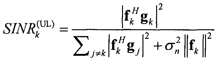
[164] 본 발명에서 제안한 송수신 필터는 다른 단말들로부터 발생하는 간섭을 제거하는 것을 목적으로 한다. 하향링크에서 간섭을 제거하기 위한 조건은 하기의 수식 11과 같다.
[165] 【수식 11】

[166] 상향링크에서 간섭을 제거하기 위한 조건은 하기의 수식 12와 같다.
[167] 【수식 12】

[168] 기지국에서 단말들의 채널 정보를 완벽하게 알고 있을 때, 위의 조건을 만족하는 송수신 필터에 대하여 당업자라면 쉽게 이해할 수 있다. 그러나 현실적으로 기지국에서 채널 정보를 완벽하게 알지 못하므로, 간섭을 완벽하게
제거하는 것은 불가능하다 . 본 발명에서 제안하는 방식은 기지국의 안테나가 증가함에 따라 점근적으로 조건을 만족하도록 설계하는 것이다. 구체적으로, 하향링크의 간섭이 점근적으로 제거될 조건은 하기의 수식 13과 같다.
[169] 【수식 13】

[170] 더불어, 상향링크의 간섭이 점근적으로 제거될 조건은 하기의 수식 14와 같다.
[171] 【수식 14]
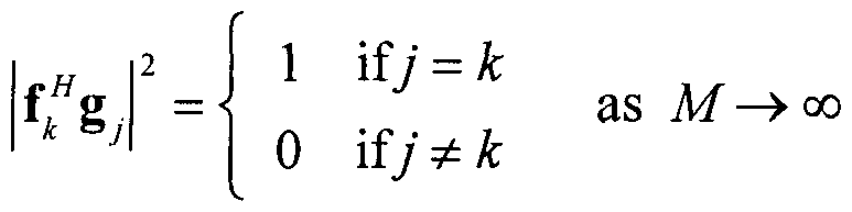
[172] 수신 필터 설계
[173] 도 15는 본 발명에서 적용하려는 수신 필터 구조의 일 실시 예를 나타내는 도면이다.
[174] 도 15에 도시된 바와 같이, 제안한 수신 필터의 구조는 두 부분으로 나뉠 수 있다. 첫 번째 부분은 각 RU 포트에서 수신 신호에 maximum ratio combining (MRC) 필터 를 사용한다. 두 번째 부분은 MRC를 통과하고 나온 결과에 post— processing 필터 tk 를 통과 시키는 것이다. L번째 RU에서 K번째 단말의 신호를 검출하기 위한 服 C필터는 하기의 수식 15와 같다.
[175] 【수식 15】
= g,k
[176] 그리고 총 수신 필터는 하기의 수식 16과 같다.
[177] 【수식 16】

[178] 이 경우 총 수신 필터로 상향링크 간섭이 점근적으로 제거될 조건은 하기의 수식 17과 같다.
[179] 【수식 17】
 [180] 일반성을 잃지 않고 1,…, 라고 가정하면, post-processing 필터 ^ ,
{ , ···, ^는 하기의 수식 18의 방법으로 얻는다.
[181] 【수식 18】

A† =AiA^A
[182] 여기서 ^는 매트릭스 A의 유사 역행렬로 이다.
[183] 송신 필터 설계
[184] 도 16은 본 발명에서 적용하려는 송신 필터 구조의 일 실시 예를 나타내는 도면이다ᅳ
[185] 도 16에 도시된 바와 같이, 제안한 수신 필터의 구조는 두 부분으로 나뉘는데, 첫 번째 부분은 pre-processing 매트릭스 필터 U^ ^uJ를 사용하고 두 번째 부분은 pre-processing 필터를 통과한 신호에 maximum ratio transmission
(M T) 필터 b 를 통과 시키는 것이다. L번째 RU에서 K번째 단말를 위한 MRT 필터는 하기의 수식 19와 같다.
[186] 【수식 19】 = g¾
[187] 그리고 총 송신 필터는 하기의 수식 20과 같다.
[188] 【수식 20】
w* = uuiik
[189] 이 경우 하향링크 간섭이 점근적으로 제거될 조건은 하기의 수식 21과 같다. L [119900J] 【수식 21】

[191] 일반성을 잃지 않고 ^ …, 라고 가정하면, pre-processing
^는 다음 수식 22의 방법으로 얻는다.
[192] 【수식 22】

[193] 도 15 및 도 16에서 MRC/MRT와 포스트 /프리 필터를 이용한 송수신 필터 설계 방법에 대한 실시 예를 살펴보았다. 종래의 송수신 필터 설계 방식과 비교하여, 추가적인 부분은 파일럿 재사용으로 인한 간섭을 제거하기 위하여 포스트 /프리 필터가 더해졌다. 이러한 포스트 /프리 필터의 형태는 행렬의 역행렬로 나타난다. 따라서 포스트 필터 ^, 프리 필터 ^를 생성하기 위한 추가적인 계산 복잡도는 이다. 참고로, s는 파일럿 재사용 팩터 Λ에 의하여 결정되고 5≤「/ᅴ를 만족한다. 결과적으로 추가적인 계산 복잡도는 0(£「즤)보다 작다.
[194] 도 17은 본 발명에 따른 파일럿 재사용 팩터 ( )를 적응적으로 변화시켜, 기지국 전체의 전송 속도를 증가하기 위한 동작의 흐름도이다.
[195] 기지국은 새로운 단말이 셀 영역에 발생하거나 기존의 단말 셀 영역에서 사라지는 경우, 새로운 사용자 association을 생성한다. 이러한 단말 정보의 변화로 인하여 사용 중인 파일럿 재사용 팩터가 비효율적일 수 있다. 이를 적웅적으로 변화시키기 위하여 기지국은 상향링크의 경우 수식 10, 하향링크의 경우 수식 12를 사용하여 모든 단말의 SINR을 계산한다. 그 후, 기지국은 상 /하향링크의 네트워크 전송량 (Network throughput)을 다음의 수식 23을 통하여 계산한다.
[196] [수식 23】

[197] 【수식 24】
C(DL) = t-P) log(l + S/A DL))
[198] 여기서 N 는 전체 직교 자원 블록의 수이다. 끝으로, 기지국은 상 /하향링크의 네트워크 전송량을 최대화하는 선택할 단말의 수 K , 파일럿 자원의 수 ^, 및 파일럿 재사용 팩터 를 결정한다.
【산업상 이용가능성】
[199] 상술한 설명에서는 본 발명을 다중 샐 협력 통신 시스템에 적용되는 형태를 중심으로 설명하였으나, 본 발명은 다양한 이동통신 시스템에 동일 또는 균등한 원리로 이용될 수 있다.
Claims
【청구의 범위】
【청구항 11
무선 통신 시스템에서 신호를 송수신하는 방법에 있어서,
기지국이 복수의 단말로부터 참조 신호 (pi lot signal)를 수신하는 단계; 상기 기지국이 수신한 상기 참조 신호 및 상기 기지국에 협력하는 협력 기지국으로부터 전달받은, 상기 협력 기지국에서 상기 복수의 단말로부터 수신한 참조 신호에 기초하여, 상기 복수의 단말과의 통신 채널을 추정하여 채널 정보를 획득하는 단계 ;
상기 기지국이 상기 획득한 채널 정보를 이용하여, 수신 필터를 결정하는 단계 ; 및
상기 복수의 단말 중 하나인 제 1 단말로부터 수신한 데이터 신호를 상기 결정된 수신 필터를 이용하여, 상기 데이터 신호에 포함된 간섭 신호를 제거하는 단계;
를 포함하고,
상기 제 1 단말로부터 수신한 참조 신호는, 상기 복수의 단말 중 상기 제 1 단말 이외의 단말로부터 수신한 참조 신호 중 하나 이상의 참조 신호와 동일하고, 상기 수신 필터는, 상기 데이터 신호에 기지국 및 단말 간의 평균 신호 파워 값으로 표현된 가중 행렬을 곱하는 방법으로 상기 간섭 신호를 제거하는, 신호 송수신 방법 .
【청구항 2】
제 1항에 있어서,
상기 수신 필터는 상기 데이터 신호를 MRC(Maximum Ratio Combining) 필터에서 필터링 된 신호에 포함된 간섭 신호를 제거하는, 신호 송수신 방법.
【청구항 3】
제 1 항에 있어서,
상기 가중 행렬 ([tl,t2, ts])은 하기의 L X S 크기의 행렬의 유사 역행렬로서, 다음과 같이 표현되며,

상기 PLS는 L번째 기지국 및 S번째 단말간의 평균 신호 파워 값이고, L은 전체 기지국의 수이고, s는 동일한 참조 신호를 전송하는 단말의 수이며, 는 매트릭스 A의 유사 역행렬로 신호 송수신 방법

【청구항 4】
제 1항에 있어서,
상기 간섭 신호는 상기 복수의 단말 중 제 1 단말 이외의 단말에서 전송된 신호인, 신호 송수신 방법 .
【청구항 5】
제 1 항에 있어서,
상기 참조 신호는, 상기 기지국에 인접한 하나 아상의 단말에서 측정된 신호 파워 정보를 상기 기지국에서 수신하여, 상기 측정된 신호 파워 정보에 기초하여 결정된 신호인, 신호 송수신 방법 . .
【청구항 6】
제 1 항에 있어서,
상기 참조 신호는, 상기 기지국에서 측정한 단말의 평균 신호 파워 정보에 기초하여 결정된 신호인, 신호 송수신 방법 .
【청구항 7】
제 6 항에 있어서,
상기 단말의 평균 신호 파워 정보는, 상기 기지국 및 상기 협력 기지국 간에 상호 교환되는, 신호 송수신 방법 .
【청구항 8]
제 6 항에 있어서,
상기 참조 신호는 상기 기지국 및 상기 협력 기지국 간에 상호 교환되는, 신호 송수신 방법 .
【청구항 9】
제 1 항에 있어서,
상기 참조 신호는, 상기 협력 기지국의 참조 신호와 동일한 자원 블록에 할당되는, 신호 송수신 방법 .
【청구항 10]
제 1 항에 있어서,
상기 참조 신호는, 상기 협력 기지국의 참조 신호와 서로 직교
(orthogonal)하는 자원 블록에 할당되는, 신호 송수신 방법.
【청구항 11]
제 1 항에 있어서,
상기 참조 신호는, 상기 협력 기지국의 참조 신호의 일부와 서로 직교 (orthogonal)하는 자원 블록에 할당되는, 신호 송수신 방법.
【청구항 12】
제 1 항에 있어서,
상기 참조 신호는, 상기 협력 기지국의 참조 신호와 서로 크기가 다른 신호인, 신호 송수신 방법 .
【청구항 13】
제 1 항에 있어서,
상기 참조 신호가 할당된 자원 블록의 수보다 채널을 추정할 수 있는 단말의 수가 적은 경우, 상기 단말은 직교 참조 신호를 상기 기지국에게 전송하는, 신호 송수신 방법 .
【청구항 14]
제 1 항에 있어서,
상기 참조 신호가 할당된 자원 블록의 수보다 채널을 추정할 수 있는 단말의 수가 많은 경우, 상기 단말은 다른 단말에서 전송하는 참조 신호와 동일한 참조 신호를 상기 기지국에게 전송하는, 신호 송수신 방법.
【청구항 15]
제 1 항에 있어서,
상기 간섭 신호는 상기 기지국의 안테나 수가 증가할수록 줄어들도록 설정되는, 신호 송수신 방법.
【청구항 16】
무선 통신 시스템에서 신호를 송수신하는 방법에 있어서,
기지국이 복수의 단말로부터 참조 신호 (pi lot signal)를 수신하는 단계; 상기 기지국이 상기 수신한 참조 신호 및 상기 기지국에 협력하는 협력 기지국으로부터 수신한 상기 복수의 단말에 대한 참조 신호에 기초하여, 상기 복수의 단말과의 통신 채널을 추정하여 채널 정보를 획득하는 단계;
상기 기지국이 상기 획득한 채널 정보를 이용하여, 송신 필터를 결정하는 단계; 및
상기 기지국은 데이터를 상기 결정된 송신 필터로 필터링하여, 상기 복수의 단말에게 전송하는 단계 ;
를 포함하고,
상기 단말로부터 수신한 참조 신호는, 상기 기지국에서 타 단말로부터 수신한 참조 신호 중 하나 이상의 참조 신호와 동일하고,
상기 송신 필터는 전송할 데이터에 대하여 기지국 및 단말 간의 평균 신호 파워 값으로 표현된 가중 행렬을 곱하는 방법으로 필터링하여 전송하는, 상기 신호 송수신 방법 .
【청구항 17】
무선 통신 시스템에서 신호를 송수신하는 기지국 장치에 있어서,
송수신기; 및
프로세서를 포함하고,
상기 프로세서는,
복수의 단말로부터 참조 신호 (pi lot signal)를 상기 송수신기를 이용하여 수신하고, 상기 수신한 참조 신호 및 상기 기지국에 협력하는 협력 기지국으로부터 수신한 상기 복수의 단말에 대한 참조 신호에 기초하여, 상기 복수의 단말과의 통신 채널을 추정하여 채널 정보를 획득하고, 상기 획득한 채널 정보를 이용하여, 수신 필터를 결정하며, 상기 복수의 단말 중 하나인 제 1 단말로부터 전송된 데이터 신호를 상기 결정된 수신 필터를 이용하여, 상기 데이터 신호에 포함된 간섭 신호를 제거하도록 설정되몌
상기 제 1 단말로부터 수신한 참조 신호는, 상기 복수의 단말 중 상기 거 U 단말 이외의 단말로부터 수신한 참조 신호 중 하나 이상의 참조 신호와 동일하고,
상기 수신 필터는 상기 데이 터 신호에 기지국 및 단말 간의 평균 신호 파워 값으로 표현된 가중 행렬을 곱하는 방법으로 상기 간섭 신호를 제거하는 , 기지국 장치 .
Priority Applications (1)
| Application Number | Priority Date | Filing Date | Title |
|---|---|---|---|
| US14/647,011 US9768940B2 (en) | 2012-12-09 | 2013-12-02 | Method and device for transmitting and receiving signal in multi-cell cooperative communication system |
Applications Claiming Priority (2)
| Application Number | Priority Date | Filing Date | Title |
|---|---|---|---|
| US201261735044P | 2012-12-09 | 2012-12-09 | |
| US61/735,044 | 2012-12-09 |
Publications (1)
| Publication Number | Publication Date |
|---|---|
| WO2014088271A1 true WO2014088271A1 (ko) | 2014-06-12 |
Family
ID=50883646
Family Applications (1)
| Application Number | Title | Priority Date | Filing Date |
|---|---|---|---|
| PCT/KR2013/011054 Ceased WO2014088271A1 (ko) | 2012-12-09 | 2013-12-02 | 다중 셀 협력 통신 시스템에서 신호 송수신하는 방법 및 이를 위한 장치 |
Country Status (2)
| Country | Link |
|---|---|
| US (1) | US9768940B2 (ko) |
| WO (1) | WO2014088271A1 (ko) |
Cited By (1)
| Publication number | Priority date | Publication date | Assignee | Title |
|---|---|---|---|---|
| WO2016150488A1 (en) * | 2015-03-24 | 2016-09-29 | Sony Corporation | Pilot signal resource allocation for a cellular mimo system |
Families Citing this family (9)
| Publication number | Priority date | Publication date | Assignee | Title |
|---|---|---|---|---|
| US10123222B2 (en) | 2013-09-13 | 2018-11-06 | Blackberry Limited | Mitigating interference in full duplex communication |
| US10110264B2 (en) * | 2013-09-13 | 2018-10-23 | Blackberry Limited | Full duplex resource reuse enablement |
| CN106797568B (zh) * | 2014-10-11 | 2019-09-20 | 华为技术有限公司 | 上行业务传输方法、装置及无线局域网的接入点 |
| US9735931B2 (en) * | 2014-10-30 | 2017-08-15 | Huawei Technologies Co., Ltd. | System and method for detecting active user equipments |
| KR102651724B1 (ko) * | 2015-08-03 | 2024-03-28 | 삼성전자주식회사 | 무선 통신 시스템에서 채널 할당 장치 및 방법 |
| CN107872298B (zh) * | 2016-09-26 | 2023-09-22 | 华为技术有限公司 | 免授权传输的方法、网络设备和终端设备 |
| EP3542486B1 (en) * | 2016-11-16 | 2021-03-24 | Telefonaktiebolaget LM Ericsson (publ) | Listen before talk for reference signals in mimo systems |
| ES3023589T3 (en) * | 2016-12-20 | 2025-06-02 | Sharp Kk | Terminal apparatus, base station apparatus, and communication method |
| CN113678480B (zh) * | 2019-04-30 | 2024-05-14 | 富士通株式会社 | 边链路数据的发送和接收方法以及装置 |
Citations (4)
| Publication number | Priority date | Publication date | Assignee | Title |
|---|---|---|---|---|
| WO2011056607A1 (en) * | 2009-10-26 | 2011-05-12 | Qualcomm Incorporated | COORDINATED MULTI-POINT (CoMP) NETWORK AND PROTOCOL ARCHITECTURE |
| WO2011072156A2 (en) * | 2009-12-09 | 2011-06-16 | Qualcomm Incorporated | Method and system for rate prediction in coordinated multi-point transmission |
| WO2011078571A2 (ko) * | 2009-12-22 | 2011-06-30 | 엘지전자 주식회사 | 프리코딩된 사운딩 참조신호를 이용하여 comp 통신을 수행하는 장치 및 그 방법 |
| US20120051265A1 (en) * | 2009-04-20 | 2012-03-01 | China Academy Of Telecommunications Technology | Method and Apparatus of Configuring Sounding Reference Signal for Coordinated Multi-Point Transmission |
Family Cites Families (26)
| Publication number | Priority date | Publication date | Assignee | Title |
|---|---|---|---|---|
| US7085240B2 (en) * | 2000-10-03 | 2006-08-01 | Kathrein-Werke Kg | Directed maximum ratio combining and scheduling of high rate transmission for data networks |
| FR2838279B1 (fr) * | 2002-04-05 | 2004-09-24 | Nortel Networks Ltd | Procede de controle de ressources radio affectees a une communication entre un terminal mobile et une infrastructure cellulaire, et equipements pour la mise en oeuvre de ce procede |
| US8705659B2 (en) * | 2003-11-06 | 2014-04-22 | Apple Inc. | Communication channel optimization systems and methods in multi-user communication systems |
| US8170081B2 (en) * | 2004-04-02 | 2012-05-01 | Rearden, LLC. | System and method for adjusting DIDO interference cancellation based on signal strength measurements |
| US8139544B1 (en) * | 2004-07-30 | 2012-03-20 | Intellectual Ventures I Llc | Pilot tone processing systems and methods |
| US7139328B2 (en) * | 2004-11-04 | 2006-11-21 | Motorola, Inc. | Method and apparatus for closed loop data transmission |
| US20070147536A1 (en) * | 2005-12-27 | 2007-06-28 | Ezer Melzer | Wireless communication device employing interference-sensitive mode selection and associated methods |
| US20150030058A9 (en) * | 2006-05-17 | 2015-01-29 | Texas Instruments Inc. | Cqi feedback for mimo deployments |
| WO2008060203A1 (en) * | 2006-11-13 | 2008-05-22 | Telefonaktiebolaget Lm Ericsson (Publ) | Method and arrangement for pilot pattern based control signalling in mimo systems |
| US7817748B2 (en) * | 2007-06-12 | 2010-10-19 | Intel Corporation | Pragmatic adaptive maximum ratio combining (MRC) and minimum mean square error (MMSE) multiple input multiple output-orthogonal frequency division multiplexing (MIMO-OFDM) receiver algorithm |
| CN101373998B (zh) * | 2007-08-20 | 2012-07-25 | 上海贝尔阿尔卡特股份有限公司 | 低信息交互的多基站协作mimo及其调度方法和装置 |
| US20090168730A1 (en) * | 2007-10-29 | 2009-07-02 | Motorola, Inc. | Pilot Signal Allocation Method and Apparatus |
| KR101526997B1 (ko) * | 2007-11-28 | 2015-06-11 | 엘지전자 주식회사 | 다수의 송신 안테나를 가진 시스템에서의 파일롯 신호 송수신 방법 |
| US8203998B2 (en) * | 2008-03-28 | 2012-06-19 | Qualcomm Incorporated | System and methods for cancelling interference in a communication system |
| US9755705B2 (en) * | 2008-08-07 | 2017-09-05 | Qualcomm Incorporated | Method and apparatus for supporting multi-user and single-user MIMO in a wireless communication system |
| US20110299617A1 (en) * | 2008-09-25 | 2011-12-08 | Mohammad Ali Maddah-Ali | X-mimo systems with multi-transmitters and multi-receivers |
| JP5221285B2 (ja) * | 2008-11-05 | 2013-06-26 | 株式会社東芝 | 無線通信装置及び方法 |
| EP2242187B1 (en) * | 2009-04-14 | 2015-10-28 | Fraunhofer-Gesellschaft zur Förderung der angewandten Forschung e.V. | Method and device for data processing in a communication network |
| JP5601803B2 (ja) * | 2009-08-06 | 2014-10-08 | シャープ株式会社 | 通信システム、通信方法及び基地局 |
| WO2011054368A1 (en) * | 2009-11-03 | 2011-05-12 | Nokia Siemens Networks Oy | Method and apparatus for interference-resistant wireless communications |
| US9197284B2 (en) * | 2010-01-15 | 2015-11-24 | Google Technology Holdings LLC | Method and apparatus for pilot signal processing in a wireless communication system |
| US9503285B2 (en) * | 2011-03-01 | 2016-11-22 | Qualcomm Incorporated | Channel estimation for reference signal interference cancelation |
| WO2012141384A1 (ko) * | 2011-04-14 | 2012-10-18 | 엘지전자 주식회사 | 다중 안테나 무선 통신 시스템에서 단말의 간섭 억제 방법 및 이를 위한 장치 |
| EP2742641B1 (en) * | 2012-01-30 | 2016-01-20 | Telefonaktiebolaget L M Ericsson (publ) | Method, apparatus, and computer programme for transmitting common and demodulation pilot signals in multi-antenna wireless communications |
| US9204434B2 (en) * | 2012-03-19 | 2015-12-01 | Qualcomm Incorporated | Enhanced sounding reference signal (SRS) operation |
| KR101669701B1 (ko) * | 2012-06-25 | 2016-10-26 | 주식회사 케이티 | 물리적 상향링크 데이터 채널 맵핑정보 제공방법 및 그 송수신포인트, 물리적 상향링크 데이터 채널의 전송방법, 그 단말 |
-
2013
- 2013-12-02 US US14/647,011 patent/US9768940B2/en active Active
- 2013-12-02 WO PCT/KR2013/011054 patent/WO2014088271A1/ko not_active Ceased
Patent Citations (4)
| Publication number | Priority date | Publication date | Assignee | Title |
|---|---|---|---|---|
| US20120051265A1 (en) * | 2009-04-20 | 2012-03-01 | China Academy Of Telecommunications Technology | Method and Apparatus of Configuring Sounding Reference Signal for Coordinated Multi-Point Transmission |
| WO2011056607A1 (en) * | 2009-10-26 | 2011-05-12 | Qualcomm Incorporated | COORDINATED MULTI-POINT (CoMP) NETWORK AND PROTOCOL ARCHITECTURE |
| WO2011072156A2 (en) * | 2009-12-09 | 2011-06-16 | Qualcomm Incorporated | Method and system for rate prediction in coordinated multi-point transmission |
| WO2011078571A2 (ko) * | 2009-12-22 | 2011-06-30 | 엘지전자 주식회사 | 프리코딩된 사운딩 참조신호를 이용하여 comp 통신을 수행하는 장치 및 그 방법 |
Non-Patent Citations (1)
| Title |
|---|
| ALCATEL -LUCENT ET AL.: "On the need of SRS Enhancement for UL CoMP", R1-120500, 3GPP TSG RAN WG1 MEETING#68, 6 February 2012 (2012-02-06) - 10 February 2012 (2012-02-10), DRESDEN, GERMANY, pages 1 - 3 * |
Cited By (3)
| Publication number | Priority date | Publication date | Assignee | Title |
|---|---|---|---|---|
| WO2016150488A1 (en) * | 2015-03-24 | 2016-09-29 | Sony Corporation | Pilot signal resource allocation for a cellular mimo system |
| US9794040B2 (en) | 2015-03-24 | 2017-10-17 | Sony Corporation | Pilot signal resource allocation for a cellular MIMO system |
| CN107431587A (zh) * | 2015-03-24 | 2017-12-01 | 索尼公司 | 用于蜂窝mimo系统的导频信号资源分配 |
Also Published As
| Publication number | Publication date |
|---|---|
| US9768940B2 (en) | 2017-09-19 |
| US20150304090A1 (en) | 2015-10-22 |
Similar Documents
| Publication | Publication Date | Title |
|---|---|---|
| US11991540B2 (en) | Method and apparatus for feeding back aggregated channel state information in cooperative multipoint communication system | |
| EP2548313B1 (en) | Method and apparatus for providing channel state information-reference signal (csi-rs) configuration information in a wireless communication system supporting multiple antennas | |
| US9749106B2 (en) | Method and device for transmitting channel state information in wireless communication system | |
| KR101905878B1 (ko) | 단말간 직접 통신을 지원하는 무선 통신 시스템에서 자원을 할당하기 위한 방법 및 이를 위한 장치 | |
| KR101910663B1 (ko) | 단말 간 통신을 지원하는 무선 통신 시스템에서 간섭 완화 방법 및 이를 위한 장치 | |
| US9768940B2 (en) | Method and device for transmitting and receiving signal in multi-cell cooperative communication system | |
| JP6373369B2 (ja) | Fdr送信を支援する無線接続システムにおいて信号送受信方法及び装置 | |
| WO2014148811A1 (ko) | 무선 통신 시스템에서 간섭을 제거하고 데이터를 수신하는 방법 및 장치 | |
| KR101938247B1 (ko) | 간섭 제거 성능이 반영된 채널 상태 보고를 위한 방법 및 이를 위한 장치 | |
| KR102318545B1 (ko) | 무선 통신 시스템에서 간섭을 제거하고 신호를 수신하는 방법 및 장치 | |
| KR20160022303A (ko) | 무선 통신 시스템에서 간섭 제거를 위한 방법 및 이를 위한 장치 | |
| KR20150135210A (ko) | 무선 통신 시스템에서 간섭 제거를 위한 방법 및 이를 위한 장치 | |
| KR20140017563A (ko) | 장치-대-장치 통신 방법 및 장치 | |
| US9762344B2 (en) | Method for transmitting and receiving signal in multi-cell cooperative communication system and apparatus therefor | |
| US9918249B2 (en) | Method and apparatus for removing interference and receiving signal in wireless communication system | |
| WO2015147570A1 (ko) | Fdr 전송을 지원하는 무선접속시스템에서 자원 할당 방법 및 장치 | |
| WO2014092366A1 (ko) | 무선 통신 시스템에서 신호 송수신하는 방법 및 이를 위한 장치 | |
| US20160345315A1 (en) | Resource allocation method and device in wireless access system supporting fdr transmission | |
| US9136930B2 (en) | Method and device for feeding back channel information in wireless communication system supporting multi-input multi-output scheme | |
| KR102318546B1 (ko) | 무선 통신 시스템에서 간섭을 제거하고 신호를 수신하는 방법 및 장치 | |
| US10057002B2 (en) | Method and apparatus for removing interference and receiving signal in wireless communication system | |
| EP3179647A1 (en) | Method and device for receiving signal in wireless access system supporting fdr transmission | |
| WO2015122733A1 (ko) | Fdr 전송을 지원하는 무선접속시스템에서 신호를 수신하는 방법 및 장치 | |
| KR20130106260A (ko) | 다중 사용자 mimo(mu-mimo) 방식을 지원하는 무선 통신 시스템에서 신호 수신 방법 및 장치 | |
| KR20170084038A (ko) | Fdr 전송을 지원하는 무선접속시스템에서 신호를 수신하는 방법 및 장치 |
Legal Events
| Date | Code | Title | Description |
|---|---|---|---|
| 121 | Ep: the epo has been informed by wipo that ep was designated in this application |
Ref document number: 13860998 Country of ref document: EP Kind code of ref document: A1 |
|
| WWE | Wipo information: entry into national phase |
Ref document number: 14647011 Country of ref document: US |
|
| NENP | Non-entry into the national phase |
Ref country code: DE |
|
| 122 | Ep: pct application non-entry in european phase |
Ref document number: 13860998 Country of ref document: EP Kind code of ref document: A1 |