WO2014086176A1 - 肌肉松弛程度测量方法、处理装置和肌松测量仪 - Google Patents
肌肉松弛程度测量方法、处理装置和肌松测量仪 Download PDFInfo
- Publication number
- WO2014086176A1 WO2014086176A1 PCT/CN2013/083093 CN2013083093W WO2014086176A1 WO 2014086176 A1 WO2014086176 A1 WO 2014086176A1 CN 2013083093 W CN2013083093 W CN 2013083093W WO 2014086176 A1 WO2014086176 A1 WO 2014086176A1
- Authority
- WO
- WIPO (PCT)
- Prior art keywords
- coordinate system
- acceleration
- sensor
- angular velocity
- motion
- Prior art date
- Legal status (The legal status is an assumption and is not a legal conclusion. Google has not performed a legal analysis and makes no representation as to the accuracy of the status listed.)
- Ceased
Links
Classifications
-
- A—HUMAN NECESSITIES
- A61—MEDICAL OR VETERINARY SCIENCE; HYGIENE
- A61B—DIAGNOSIS; SURGERY; IDENTIFICATION
- A61B5/00—Measuring for diagnostic purposes; Identification of persons
- A61B5/103—Measuring devices for testing the shape, pattern, colour, size or movement of the body or parts thereof, for diagnostic purposes
- A61B5/11—Measuring movement of the entire body or parts thereof, e.g. head or hand tremor or mobility of a limb
-
- A—HUMAN NECESSITIES
- A61—MEDICAL OR VETERINARY SCIENCE; HYGIENE
- A61B—DIAGNOSIS; SURGERY; IDENTIFICATION
- A61B5/00—Measuring for diagnostic purposes; Identification of persons
- A61B5/103—Measuring devices for testing the shape, pattern, colour, size or movement of the body or parts thereof, for diagnostic purposes
- A61B5/11—Measuring movement of the entire body or parts thereof, e.g. head or hand tremor or mobility of a limb
- A61B5/1121—Determining geometric values, e.g. centre of rotation or angular range of movement
-
- A—HUMAN NECESSITIES
- A61—MEDICAL OR VETERINARY SCIENCE; HYGIENE
- A61B—DIAGNOSIS; SURGERY; IDENTIFICATION
- A61B5/00—Measuring for diagnostic purposes; Identification of persons
- A61B5/22—Ergometry; Measuring muscular strength or the force of a muscular blow
-
- A—HUMAN NECESSITIES
- A61—MEDICAL OR VETERINARY SCIENCE; HYGIENE
- A61B—DIAGNOSIS; SURGERY; IDENTIFICATION
- A61B5/00—Measuring for diagnostic purposes; Identification of persons
- A61B5/45—For evaluating or diagnosing the musculoskeletal system or teeth
- A61B5/4519—Muscles
-
- A—HUMAN NECESSITIES
- A61—MEDICAL OR VETERINARY SCIENCE; HYGIENE
- A61B—DIAGNOSIS; SURGERY; IDENTIFICATION
- A61B5/00—Measuring for diagnostic purposes; Identification of persons
- A61B5/48—Other medical applications
- A61B5/4836—Diagnosis combined with treatment in closed-loop systems or methods
-
- A—HUMAN NECESSITIES
- A61—MEDICAL OR VETERINARY SCIENCE; HYGIENE
- A61B—DIAGNOSIS; SURGERY; IDENTIFICATION
- A61B5/00—Measuring for diagnostic purposes; Identification of persons
- A61B5/72—Signal processing specially adapted for physiological signals or for diagnostic purposes
- A61B5/7271—Specific aspects of physiological measurement analysis
- A61B5/7278—Artificial waveform generation or derivation, e.g. synthesizing signals from measured signals
-
- A—HUMAN NECESSITIES
- A61—MEDICAL OR VETERINARY SCIENCE; HYGIENE
- A61N—ELECTROTHERAPY; MAGNETOTHERAPY; RADIATION THERAPY; ULTRASOUND THERAPY
- A61N1/00—Electrotherapy; Circuits therefor
- A61N1/02—Details
- A61N1/04—Electrodes
- A61N1/0404—Electrodes for external use
- A61N1/0408—Use-related aspects
- A61N1/0452—Specially adapted for transcutaneous muscle stimulation [TMS]
-
- A—HUMAN NECESSITIES
- A61—MEDICAL OR VETERINARY SCIENCE; HYGIENE
- A61N—ELECTROTHERAPY; MAGNETOTHERAPY; RADIATION THERAPY; ULTRASOUND THERAPY
- A61N1/00—Electrotherapy; Circuits therefor
- A61N1/02—Details
- A61N1/04—Electrodes
- A61N1/0404—Electrodes for external use
- A61N1/0472—Structure-related aspects
- A61N1/0492—Patch electrodes
-
- A—HUMAN NECESSITIES
- A61—MEDICAL OR VETERINARY SCIENCE; HYGIENE
- A61N—ELECTROTHERAPY; MAGNETOTHERAPY; RADIATION THERAPY; ULTRASOUND THERAPY
- A61N1/00—Electrotherapy; Circuits therefor
- A61N1/18—Applying electric currents by contact electrodes
- A61N1/20—Applying electric currents by contact electrodes continuous direct currents
-
- A—HUMAN NECESSITIES
- A61—MEDICAL OR VETERINARY SCIENCE; HYGIENE
- A61B—DIAGNOSIS; SURGERY; IDENTIFICATION
- A61B2562/00—Details of sensors; Constructional details of sensor housings or probes; Accessories for sensors
- A61B2562/02—Details of sensors specially adapted for in-vivo measurements
- A61B2562/0219—Inertial sensors, e.g. accelerometers, gyroscopes, tilt switches
-
- A—HUMAN NECESSITIES
- A61—MEDICAL OR VETERINARY SCIENCE; HYGIENE
- A61B—DIAGNOSIS; SURGERY; IDENTIFICATION
- A61B2562/00—Details of sensors; Constructional details of sensor housings or probes; Accessories for sensors
- A61B2562/22—Arrangements of medical sensors with cables or leads; Connectors or couplings specifically adapted for medical sensors
- A61B2562/221—Arrangements of sensors with cables or leads, e.g. cable harnesses
- A61B2562/222—Electrical cables or leads therefor, e.g. coaxial cables or ribbon cables
-
- A—HUMAN NECESSITIES
- A61—MEDICAL OR VETERINARY SCIENCE; HYGIENE
- A61B—DIAGNOSIS; SURGERY; IDENTIFICATION
- A61B5/00—Measuring for diagnostic purposes; Identification of persons
- A61B5/48—Other medical applications
- A61B5/4821—Determining level or depth of anaesthesia
-
- A—HUMAN NECESSITIES
- A61—MEDICAL OR VETERINARY SCIENCE; HYGIENE
- A61N—ELECTROTHERAPY; MAGNETOTHERAPY; RADIATION THERAPY; ULTRASOUND THERAPY
- A61N1/00—Electrotherapy; Circuits therefor
- A61N1/18—Applying electric currents by contact electrodes
- A61N1/32—Applying electric currents by contact electrodes alternating or intermittent currents
- A61N1/36—Applying electric currents by contact electrodes alternating or intermittent currents for stimulation
- A61N1/36014—External stimulators, e.g. with patch electrodes
Definitions
- the present application relates to the field of medical devices, and particularly relates to a method for measuring muscle relaxation degree, a treatment device, and a muscle relaxation measuring instrument.
- the patient may have some undesired movements, or the patient's muscles may be in a certain degree of relaxation. Therefore, it is necessary to inject the patient with a drug that relaxes the muscles, such as muscle relaxants. After the injection of the drug, it is usually necessary to perform a muscle relaxation monitoring on the patient to quantitatively evaluate the degree of muscle relaxation of the patient.
- the monitoring of the degree of muscle relaxation can be measured by measuring the contractile strength of the short-receiving muscle of the patient's thumb, because the contractile force reflects the degree of muscle relaxation. According to Newton's theorem, the force is proportional to the acceleration. By measuring the acceleration generated by the thumb movement, it can be obtained indirectly. The contraction force of the thumb short muscles.
- a common method for measuring the degree of muscle relaxation is to use an acceleration sensor to measure the acceleration value generated by the thumb motion to output an acceleration sample value, and then derive the angular velocity value from the acceleration value through a certain motion hypothesis, but the motion hypothesis and the actual movement of the thumb exist. Deviation, resulting in inaccurate measurement of muscle relaxation. For example, assuming that the movement of the thumb is a circular motion of the thumb around a fixed point (such as the base of the thumb), the acceleration can be determined by time integral, and the angular velocity can be obtained by dividing the line speed by the estimated thumb length. This will give you all the information you need for muscle relaxation measurements. Obviously, the actual movement of the thumb is not entirely circular motion around the root of the thumb, so such motion assumptions will introduce errors into the measurement results.
- the present application provides a method for measuring muscle relaxation degree, comprising the following steps:
- the acceleration sample value of the portion to be measured is obtained from the acceleration sensor or the speed sensor.
- the angular velocity sample value of the portion to be measured is obtained from the angular velocity sensor.
- the present application provides a muscle relaxation measurement processing apparatus, including: a receiving unit, configured to acquire an acceleration sampling value of a portion to be measured from an acceleration sensor or a speed sensor, and acquire a portion to be measured from the angular velocity sensor. Angular velocity sample value.
- the present application provides a muscle relaxation measuring instrument, comprising: a constant current source for generating a stimulation current, and applying a current stimulation to a detected object through a current output end.
- the response signal extraction end includes an acceleration sensor and an angular velocity sensor, or the response signal extraction end includes a velocity sensor and an angular velocity sensor.
- the processor is connected to the constant current source, and is configured to control the constant current source to generate the stimulation current; the processor is further connected to the response signal extraction end for acquiring the acceleration from the motion information outputted by the response signal extraction end
- the sampled value and the angular velocity sampled value are calculated, and the degree of muscle relaxation is calculated based on the acceleration sample value and the angular velocity sample value.
- the acceleration sampling value and the angular velocity sampling value of the to-be-measured portion can be simultaneously obtained, and the degree of muscle relaxation is calculated according to the acceleration sampling value and the angular velocity sampling value, because the calculation result combines the to-be-measured portion.
- the acceleration sample value and the angular velocity sample value therefore, the calculation result is more accurate.
- the acceleration sensor and the angular velocity sensor or the velocity sensor and the angular velocity sensor are combined to obtain the acceleration sampling value and the angular velocity sampling value of the to-be-measured portion, so that the muscle relaxation measuring device can be placed at any position of the to-be-measured portion without Affect the accuracy of the measurement results.
- Figure la is a schematic view showing the degree of muscle relaxation of a muscle relaxometer by a thumb in an embodiment of the present application
- Figure 1b is a schematic structural view of a muscle relaxation measuring instrument according to an embodiment of the present application.
- FIG. 2 is a flow chart of a method for measuring the degree of muscle relaxation in an embodiment of the present application
- FIG. 3a is a coordinate system in which an acceleration sensor and an angular velocity sensor are disposed in an embodiment of the present application
- Figure 3b is a reference coordinate system obtained by rotating the coordinate system of the acceleration sensor of Figure 3a;
- FIG. 4 is a schematic block diagram of a muscle relaxation measurement processing device according to an embodiment of the present application.
- the muscle relaxation measuring instrument provided in this embodiment includes a processor 201, a constant current source 202, and a response signal extracting end 203.
- the processor 201 is coupled to the constant current source 202 for controlling the constant current source 202 to generate a stimulation current.
- the current output end of the constant current source 202 is connected to two electrodes through a pair of cables during measurement, and the two electrodes can be attached to a certain part of the body of the subject, as shown in FIG.
- the response signal extraction end 203 is attached to the thumb of the subject.
- the processor 201 is also in communication with the response signal extraction terminal 203, performs data interaction with the response signal extraction terminal 203, for example, receives motion information output by the response signal extraction terminal 203, and calculates the degree of muscle relaxation based on the motion information.
- the processor 201 can also The configuration, calibration, and/or identity information is sent to the response signal extraction terminal 203.
- Communication connections include wired and wireless connections.
- the response signal extraction terminal 203 includes an acceleration sensor and an angular velocity sensor
- the acceleration sensor refers to a sensor that senses the acceleration of the detected object and converts it into an electrical signal output.
- the angular velocity sensor refers to a sensor that senses the angular velocity of the detected object and converts it into an electrical signal output.
- the acceleration sensor can output real-time acceleration information
- the angular velocity sensor can output real-time angular velocity information
- the response signal extraction terminal 203 transmits the acceleration information and the angular velocity information to the processor 201
- the acceleration information and the angular velocity information can be analog electrical signals. It can also be a digital signal, which can be continuous waveform data or discrete sample values.
- the processor 201 obtains the acceleration sample value and the angular velocity sample value from the acceleration information and the angular velocity information, and then calculates the muscle relaxation degree based on the acceleration sample value and the angular velocity sample value.
- the response signal extracting end 203 includes a speed sensor and an angular velocity sensor.
- the speed sensor refers to a sensor that can sense the moving speed of the detected object.
- the response signal extracting end 203 can directly output the speed information and the time information, or can be based on The velocity information and the time information calculate the acceleration and convert the acceleration information into an electrical signal output.
- the processor 201 obtains the information obtained from the response signal extracting end 203 in addition to the angular velocity information, and the speed information or the acceleration information.
- the processor 201 may according to the speed information and The time information calculates the acceleration.
- the processor 201 calculates the degree of muscle relaxation based on the acceleration information and the angular velocity information.
- the processor 201 uses the following scheme to calculate the degree of muscle relaxation based on the acceleration sample value and the angular velocity sample value:
- the processor 201 calculates a rotation angle from the initial coordinate system to the reference coordinate system according to the initial gravity acceleration component, calculates a transformation matrix of the initial coordinate system to the reference coordinate system according to the rotation angle, and obtains a reference coordinate according to the transformation matrix of the initial coordinate system to the reference coordinate system.
- the reference coordinate system is obtained by converting the coordinate system of the initial acceleration (ie, the initial coordinate system), corresponding to a transformation matrix. Different conversion matrices correspond to different reference coordinate systems, which can be determined according to specific conditions.
- the case of a single cartridge is to convert the coordinate system of the initial acceleration so that the gravity acceleration has a component only in a certain dimension of the reference coordinate system, and the other dimension component is 0, which will be post-processing.
- the processor 201 analyzes and processes the angular velocity sampling value to obtain a rotation angle of the to-be-measured portion along the moving direction of each axis, and obtains a motion state vector according to the rotation angle of the to-be-measured portion along the moving direction of each axis.
- the processor The motion state vector is obtained by the inertial navigation algorithm.
- the inertial navigation algorithm is an algorithm for solving the motion of the object in motion through the data measured by the gyroscope equal angular velocity sensor. For example, it may be a Bika algorithm or a multi-sample rotation vector algorithm. The motion state vector of the part to be measured.
- the motion state vector represents the motion information of the part to be measured after being stimulated, and the initial coordinate system to the motion coordinate is obtained according to the motion state vector.
- the motion information includes at least acceleration information or speed information and angular velocity information when the part to be measured moves.
- the processor 201 acquires the gravitational acceleration at t from the acceleration sensor or the speed sensor.
- the transformation matrix of the initial coordinate system; the transformation matrix between the initial coordinate system and the motion coordinate system is calculated according to the angular velocity sample value; the transformation matrix from the reference coordinate system to the initial coordinate system and the transformation matrix between the initial coordinate system and the motion coordinate system Find the transformation matrix between the reference coordinate system and the motion coordinate system.
- the processor 201 calculates a conversion matrix between the reference coordinate system and the motion coordinate system according to the acceleration sample value output by the acceleration sensor or the speed sensor at t k and the angular velocity sample value output by the angular velocity sensor, and the projection component according to the gravity acceleration in the reference coordinate system.
- the transformation matrix between the reference coordinate system and the motion coordinate system is used to obtain the component of the gravity acceleration in the acceleration sensor coordinate system or the velocity sensor coordinate system, and t k is the moment after the electrical stimulation is issued, and the motion coordinate system is t k
- the coordinate system in which the acceleration sensor or the velocity sensor is located, and the component of the gravity acceleration in the reference coordinate system is [0, 1, 0].
- the processor 201 calculates a component of the gravity acceleration in the acceleration sensor or the velocity sensor coordinate system according to the acceleration sampling value and the angular velocity sampling value, and subtracts the acceleration acceleration component from the acceleration acceleration component to obtain the true acceleration in the coordinate system where the acceleration sensor or the velocity sensor is located.
- the component combines the components of the real acceleration to obtain the acceleration value generated by the actual motion of the part to be measured, and calculates the degree of muscle relaxation based on the acceleration value.
- the muscle relaxation measuring instrument senses the movement of the part to be measured by the acceleration sensor and the angular velocity sensor, and outputs the real-time acceleration sampling value and the angular velocity sampling value, and the muscle relaxation measuring instrument calculates the muscle relaxation degree according to the acceleration sampling value and the angular velocity sampling value, and calculates The result combines the acceleration sample value and the angular velocity sample value of the part to be measured, and eliminates the influence of gravity in the calculation process, so that the calculation result has higher accuracy.
- the muscle relaxation measuring device of the muscle relaxation measuring instrument can be placed at any position of the site to be measured without affecting the accuracy of the measurement result.
- the angular velocity sensor may be specifically a gyro sensor.
- the muscle relaxometer further includes a display 204, and the processor 201 transmits the muscle relaxation degree calculation result to the display 204 for display.
- the following describes how the processor 201 performs muscle relaxation measurement based on the acceleration sample value and the angular velocity sample value by taking the response signal extraction end 203 in a three-dimensional coordinate system and measuring the degree of muscle relaxation by the thumb.
- the measuring device of the muscle relaxation measuring instrument is installed at any position of the thumb and has the same motion state as the thumb.
- X a , Y a , Z a are the three axes of the coordinate system in which the acceleration sensor is located
- X b , Y b and Z b are the three axes of the coordinate system in which the angular velocity sensor is located.
- the instrument performs current stimulation on the detected object through the two electrodes connected to the wrist, and the detected object is stimulated and the thumb occurs.
- the motion, acceleration sensor and angular velocity sensor respectively output the three-axis acceleration sample value and the three-axis angular velocity sample value when the thumb moves.
- the processor 201 calculates a three-axis component of the gravity acceleration in the acceleration sensor coordinate system according to the three-axis acceleration sampling value and the three-axis angular velocity sampling value, and subtracts the component of the gravity acceleration in the acceleration sensor coordinate system from the three-axis acceleration sampling value.
- the real acceleration component of the measurement part is subjected to a composite operation of the component of the real acceleration to obtain an acceleration value generated by the actual motion of the portion to be measured, and the degree of muscle relaxation is calculated based on the acceleration value.
- the initial coordinate system of the acceleration sensor is A t .
- the initial coordinate system A t for the initial coordinate system A t .
- Rotation is performed to obtain a reference coordinate system R.
- the reference coordinate system R is a coordinate system having an axis coincident with the direction of gravity acceleration.
- the reference coordinate system R may be such that the component of gravity acceleration is [0, The coordinate system of 1 , 0].
- the reference coordinate system R can be obtained by rotating the initial coordinate system.
- the initial coordinate system A t can be used. Rotate the ⁇ angle along the z-axis and rotate the ⁇ angle along the X-axis to obtain the reference coordinate system R, where:
- Rotation angle among them, A t The acceleration component of the lower acceleration sensor along the x, y, and z axes.
- the processor 201 obtains the conversion matrix of the initial coordinate system ⁇ ⁇ around the z-axis according to the rotation angle ⁇ cos ⁇ sin ⁇ 0]
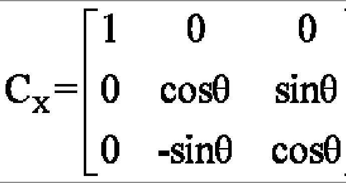
- the processor 201 obtains an initial coordinate system A t according to the rotation angle. Conversion matrix around the X axis
- the processor 201 obtains the reference coordinate system R from the conversion matrix C z , C x to the initial sitting Conversion matrix of the taxonomy A t()
- the reference coordinate system R can also be used to the initial coordinate system A t by other rotation modes. Rotation is obtained. At this time, the conversion matrix of the initial coordinate system 0 around the 2 X axis obtained by the processor 201 will not be the same as the above.
- the processor 201 When the to-be-measured portion is subjected to the current stimulation motion, the processor 201 performs an integral operation on the three-axis angular velocity sampling values output by the angular velocity sensor to obtain a rotation angle ⁇ ⁇ , ⁇ ⁇ , ⁇ ⁇ of the to-be-measured portion along the three-axis direction, and then according to The angle of rotation of the part to be measured along the three axes
- ⁇ ⁇ , ⁇ , ⁇ ⁇ can be obtained to represent the quaternion qo(t k ), qi(t k ), q 2 (t k ), q 3 (t k ) of the motion information of the to-be-measured part after being stimulated. ).
- the motion information includes at least acceleration information and angular velocity information when the portion to be measured moves.
- the processor 201 obtains the quaternion by using the card algorithm.
- the quaternion of the to-be-measured portion in the motion state can also be obtained by using a multi-subsample rotation vector algorithm.
- the quaternion algorithm used by the processor 201 in this embodiment should not be understood as the quaternary number of the present application. limited.
- the processor 201 finds the initial coordinate system A t based on the obtained quaternion.
- the transformation matrix between the motion coordinate systems A tk at which the acceleration sensor is located at any time when the part to be measured is stimulated q 0 (t k ) 2 +qi(t k ) 2 -q 2 (t k ) 2 -q 3 (t k ) 2[q 1 (t k )q 2 (t k )-q 0 (t k ) q 3 (t k )]
- the processor 201 obtains a transformation matrix between the reference coordinate R and the motion coordinate system A tk by the formula RR .
- the acceleration sampling value and the angular velocity sampling value can also be used, and the influence of the gravitational acceleration is removed by coordinate transformation.
- the muscle relaxation measuring instrument provided in this embodiment obtains the true acceleration component of the to-be-measured portion by subtracting the acceleration sampling value from the component of the acceleration acceleration coordinate system to eliminate the influence of the gravity acceleration on the measurement result and improve the measurement accuracy.
- the processor 201 may be an integrated chip or a plurality of integrated chips recorded with a program that can implement the above functions.
- Embodiment 2
- the method for measuring muscle relaxation degree includes the following steps:
- Step 101 When the object to be measured moves after being stimulated by the current, the acceleration sensor outputs a sample value of the triaxial acceleration of the measurement part.
- Step 102 The angular velocity sensor outputs a sample value of the triaxial angular velocity of the portion to be measured.
- Step 103 The instrument obtains a three-axis component of the gravity acceleration in the acceleration sensor coordinate system according to the three-axis acceleration sampling value and the three-axis angular velocity sampling value.
- Step 104 The instrument subtracts the triaxial component of the gravity acceleration obtained in step 103 from the three-axis acceleration sample value in the acceleration sensor coordinate system to obtain a true acceleration component of the to-be-measured portion.
- Step 105 Combine the real acceleration components of the to-be-measured portion obtained in step 104. Cheng, obtain the acceleration value ⁇ L ⁇ L generated by the actual motion of the part to be measured, and then extract the effective peak information of the combined acceleration as the actual acceleration generated by the motion of the part to be measured, substitute it into the calculation of muscle relaxation degree, and calculate the result Output.
- the step 103 determines the three-axis component of the gravity acceleration in the acceleration sensor coordinate system according to the three-axis acceleration sampling value and the three-axis angular velocity sampling value:
- FIG. 3a is the coordinate system where the acceleration sensor and the angular velocity sensor are located, where X a , Y a , Z a are the three axes of the coordinate system in which the acceleration sensor is located, and X b , Y b , Z b are the angular velocity sensors.
- FIG. 3b which is a reference coordinate system R obtained by rotating the coordinate system in which the acceleration sensor is located in FIG. 3a, where X R , Y R , Z R are three axes of the reference coordinate system R, at the reference coordinates.
- the component of gravity acceleration in the three axes is [0, 1, 0].
- the initial coordinate system of the acceleration sensor is A t .
- a t for the initial coordinate system A t .
- Rotation is performed to obtain a reference coordinate system R such that the component of the gravitational acceleration in the reference coordinate system R is [0, 1, 0].
- the initial coordinate system At () is rotated by an angle along the z-axis, and then rotated along the X-axis to obtain a reference coordinate system R, wherein the rotation angle is
- the initial coordinate system A t is obtained from the rotation angle ⁇ . Conversion matrix around the z-axis
- the reference coordinate system R is obtained from the transformation matrix C Z , C X to the initial coordinate system A t . Conversion moment
- the reference coordinate system R can also be used to the initial coordinate system A t by other rotation modes.
- the rotation is obtained, at this time, the initial coordinate system A t .
- the conversion matrix around the z and X axes will no longer be the same as above.
- the three-axis angular velocity sampling values output by the angular velocity sensor are respectively analyzed and processed to obtain the rotation angle of the to-be-measured portion along the three-axis direction.
- the rotation angle of the portion to be measured along the three-axis direction is obtained by integral calculation, and then, according to the rotation angle of the portion to be measured along the three-axis direction
- ⁇ 0 ⁇ 9 ⁇ finds a motion state vector which can represent the motion information of the to-be-measured part after being stimulated, and the motion information includes at least acceleration information and angular velocity information when the part to be measured is moved.
- the motion The state vector is a quaternion q. (t k ), qi (t k ), q 2 (t k ), q 3 (t k ).
- the motion state of the to-be-measured portion is obtained by the card algorithm.
- the quaternion of the part to be measured in the motion state can also be obtained by a multi-sample rotation vector algorithm, etc.
- the quaternion algorithm used in the present embodiment is not to be construed as limiting the present application.
- the initial coordinate system A t is obtained from the obtained quaternion.
- the transformation matrix between the motion coordinate systems A tk at which the acceleration sensor is located at any time when the part to be measured is stimulated q 0 (t k ) 2 +qi(t k ) 2 -q 2 (t k ) 2 -q 3 (t k ) 2[q 1 (t k )q 2 (t k )-q 0 (t k ) q 3 (t k )] 2[q 1 (t k )q 2 (t k )+q 0 (t k )q 3 (t k )] qo(t k ) 2 -qi(t k ) 2+ q2(t k ) 2 -q 3 (t k )
- the method for measuring the degree of muscle relaxation provides the acceleration sampling value as an angular velocity sampling value by the acceleration sensor and the angular velocity sensor to calculate the degree of muscle relaxation, and the influence of the gravity acceleration on the measurement result is eliminated during the calculation, thereby improving the measurement accuracy and making the measurement accuracy
- the corresponding measuring device can be placed anywhere in the part to be measured without affecting the measurement results.
- the embodiment provides a muscle relaxation measurement processing apparatus, including a processing module 401 and a receiving unit 2011.
- the processing module 401 is connected to the constant current source 202, and the constant current source 202 is controlled to generate a stimulation current to current spurt the object to be detected through the current output terminal of the constant current source 202.
- the response signal extracting end 203 is placed on the to-be-measured portion and has the same motion state as the portion to be measured.
- the response signal extracting end 203 senses and outputs the motion information of the measured portion, and the response signal.
- the extraction end 203 includes an acceleration sensor and an angular velocity sensor, or the response signal extraction terminal 203 includes a velocity sensor and an angular velocity sensor.
- the current output terminal of the constant current source 202 is further connected to the processing module 401, and the constant current source 202 feeds back the output current to the processing module 401 for monitoring, and ensures that the output current magnitude and the like are acceptable to the detected object.
- the processing module 401 includes a gravity acceleration reduction unit 2012, a synthesizing unit 2013, and a muscle relaxation calculation unit 2014.
- the receiving unit 2011 is configured to acquire an acceleration sampling value of the to-be-measured portion from the acceleration sensor, and obtain an angular velocity sampling of the to-be-measured portion from the angular velocity sensor.
- the gravity acceleration reduction unit 2012 includes a first subunit and a second subunit, the first sub The element is used to obtain the component of the gravity acceleration in the acceleration sensor coordinate system according to the acceleration sampling value and the angular velocity sampling value; the second sub-unit is used to subtract the acceleration sampling value from the acceleration acceleration component in the acceleration sensor coordinate system, and obtain the to-be-measured a true acceleration component of the part; the synthesizing unit 2013 is configured to synthesize the obtained component of the true acceleration of the to-be-measured part,
- the acceleration value V ax a y az generated by the actual movement of the part to be measured, the muscle relaxation calculation unit 2014 is used to extract the effective peak information of the combined acceleration, and is used as the actual acceleration generated by the movement of the part to be measured, and is substituted into the calculated muscle relaxation degree, and The calculation result is output.
- the first subunit of the gravity acceleration reduction unit 2012 calculates the reference coordinate system to the motion coordinate system based on the acceleration sample value and the angular velocity sample value of the portion to be measured at the time t k obtained from the acceleration sensor and the angular velocity sensor.
- the transformation matrix multiplies the projection component of the gravity acceleration in the reference coordinate system with the transformation matrix between the reference coordinate system and the motion coordinate system to obtain the component of the gravity acceleration in the motion coordinate system, and the time t k is after the electrical stimulation is issued.
- the motion coordinate system is the coordinate system where the acceleration sensor is located at time t k , the reference coordinate system is obtained by rotating the initial coordinate system, and the gravity acceleration has a projection component in the reference coordinate system, and the initial coordinate system is before the electrical stimulation is issued.
- the coordinate system where the acceleration sensor or the speed sensor is located at any time when the part to be measured is at rest for example, the reference coordinate system is a coordinate system in which the component of the gravity acceleration is [0, 1, 0], and the gravity acceleration is in the reference coordinate system.
- the projection component in is [0, 1 , 0] ⁇ .
- the first subunit acquires the gravitational acceleration at t from the acceleration sensor when calculating the transformation matrix between the reference coordinate system and the motion coordinate system.
- the transformation matrix of the initial coordinate system; the transformation matrix between the initial coordinate system and the motion coordinate system is calculated according to the angular velocity sample value; the transformation matrix of the reference coordinate system to the initial coordinate system and the transformation matrix between the initial coordinate system and the motion coordinate system Multiply the transformation matrix between the reference coordinate system and the motion coordinate system.
- the first subunit calculates a rotation angle from the initial coordinate system to the reference coordinate system according to the initial gravity component when calculating the transformation matrix of the reference coordinate system to the initial coordinate system based on the initial gravity component, and calculates the rotation angle from the initial coordinate system to the reference coordinate system.
- the transformation matrix of the initial coordinate system to the reference coordinate system, and the conversion matrix of the reference coordinate system to the initial coordinate system is obtained according to the transformation matrix of the initial coordinate system to the reference coordinate system; the first subunit obtains the initial coordinate system to the motion according to the angular velocity sampling value When the transformation matrix between the coordinate systems is used, the angular velocity sampling value is analyzed and processed to obtain the rotation angle of the portion to be measured along the movement direction of each axis.
- the rotation angle of the portion to be measured along the movement direction of each axis can be obtained by integral calculation, and then A rotation state of the to-be-measured portion along the movement direction of each axis is obtained to obtain a motion state vector indicating motion information of the to-be-measured portion after being stimulated, and a transformation matrix between the initial coordinate system and the motion coordinate system is obtained according to the motion state vector.
- the motion state vector is a quaternion, and a transformation matrix between the initial coordinate system and the motion coordinate system is obtained according to the quaternion.
- the muscle relaxation measurement processing device obtains the acceleration sampling value and the angular velocity sampling value through the acceleration sensor and the angular velocity sensor to calculate the degree of muscle relaxation, and the influence of the gravity acceleration on the measurement result is eliminated during the calculation process, thereby improving the measurement accuracy and correspondingly
- the muscle relaxation measuring device can be placed anywhere in the site to be measured without affecting the measurement results.
- the muscle relaxation measurement processing device may be an integrated chip or a plurality of integrated chips on which a program for realizing the above functions is recorded.
Landscapes
- Health & Medical Sciences (AREA)
- Life Sciences & Earth Sciences (AREA)
- Engineering & Computer Science (AREA)
- Animal Behavior & Ethology (AREA)
- Veterinary Medicine (AREA)
- Public Health (AREA)
- General Health & Medical Sciences (AREA)
- Biomedical Technology (AREA)
- Physics & Mathematics (AREA)
- Biophysics (AREA)
- Heart & Thoracic Surgery (AREA)
- Pathology (AREA)
- Surgery (AREA)
- Medical Informatics (AREA)
- Molecular Biology (AREA)
- Nuclear Medicine, Radiotherapy & Molecular Imaging (AREA)
- Radiology & Medical Imaging (AREA)
- Dentistry (AREA)
- Physiology (AREA)
- Oral & Maxillofacial Surgery (AREA)
- Physical Education & Sports Medicine (AREA)
- Geometry (AREA)
- Artificial Intelligence (AREA)
- Computer Vision & Pattern Recognition (AREA)
- Psychiatry (AREA)
- Signal Processing (AREA)
- Orthopedic Medicine & Surgery (AREA)
- Rheumatology (AREA)
- Measurement Of The Respiration, Hearing Ability, Form, And Blood Characteristics Of Living Organisms (AREA)
Abstract
Description





Claims
Priority Applications (2)
| Application Number | Priority Date | Filing Date | Title |
|---|---|---|---|
| US14/649,872 US10610151B2 (en) | 2012-12-05 | 2013-09-09 | Method for measuring level of muscle relaxation, processing device thereof and instrument for measuring muscle relaxation |
| US16/842,460 US11819325B2 (en) | 2012-12-05 | 2020-04-07 | Method for measuring level of muscle relaxation, processing device thereof and instrument for measuring muscle relaxation |
Applications Claiming Priority (2)
| Application Number | Priority Date | Filing Date | Title |
|---|---|---|---|
| CN201210516753.9A CN103845065B (zh) | 2012-12-05 | 2012-12-05 | 肌肉松弛程度测量方法、处理装置和肌松测量仪 |
| CN201210516753.9 | 2012-12-05 |
Related Child Applications (2)
| Application Number | Title | Priority Date | Filing Date |
|---|---|---|---|
| US14/649,872 A-371-Of-International US10610151B2 (en) | 2012-12-05 | 2013-09-09 | Method for measuring level of muscle relaxation, processing device thereof and instrument for measuring muscle relaxation |
| US16/842,460 Continuation US11819325B2 (en) | 2012-12-05 | 2020-04-07 | Method for measuring level of muscle relaxation, processing device thereof and instrument for measuring muscle relaxation |
Publications (1)
| Publication Number | Publication Date |
|---|---|
| WO2014086176A1 true WO2014086176A1 (zh) | 2014-06-12 |
Family
ID=50853498
Family Applications (1)
| Application Number | Title | Priority Date | Filing Date |
|---|---|---|---|
| PCT/CN2013/083093 Ceased WO2014086176A1 (zh) | 2012-12-05 | 2013-09-09 | 肌肉松弛程度测量方法、处理装置和肌松测量仪 |
Country Status (3)
| Country | Link |
|---|---|
| US (2) | US10610151B2 (zh) |
| CN (1) | CN103845065B (zh) |
| WO (1) | WO2014086176A1 (zh) |
Families Citing this family (5)
| Publication number | Priority date | Publication date | Assignee | Title |
|---|---|---|---|---|
| US10716517B1 (en) * | 2014-11-26 | 2020-07-21 | Cerner Innovation, Inc. | Biomechanics abnormality identification |
| CN104970803A (zh) * | 2015-07-08 | 2015-10-14 | 中国医学科学院生物医学工程研究所 | 一种同时具有脉搏血氧检测和肌松监测功能的探头 |
| CN111694429B (zh) * | 2020-06-08 | 2023-06-02 | 北京百度网讯科技有限公司 | 虚拟对象驱动方法、装置、电子设备及可读存储 |
| CN115235342A (zh) * | 2022-07-27 | 2022-10-25 | 北京悦动双成科技有限公司 | 确定动作的方法以及三维传感器 |
| CN117717342B (zh) * | 2024-02-07 | 2024-04-09 | 吉林大学 | 用于盆底康复的评估系统及方法 |
Citations (6)
| Publication number | Priority date | Publication date | Assignee | Title |
|---|---|---|---|---|
| US6315736B1 (en) * | 1999-06-09 | 2001-11-13 | Colin Corporation | Anesthetic-depth monitor apparatus |
| US20070027631A1 (en) * | 2005-07-29 | 2007-02-01 | Cabrera Michael Normann B | Apparatus and method for evaluating a hypertonic condition |
| WO2008031209A1 (en) * | 2006-09-16 | 2008-03-20 | Terence Gilhuly | Improved sensors and sensing for monitoring neuromuscular blockade |
| CN201643223U (zh) * | 2010-04-08 | 2010-11-24 | 广西威利方舟科技有限公司 | 闭环肌松注射装置 |
| US8187209B1 (en) * | 2005-03-17 | 2012-05-29 | Great Lakes Neurotechnologies Inc | Movement disorder monitoring system and method |
| CN102525490A (zh) * | 2010-12-22 | 2012-07-04 | 财团法人工业技术研究院 | 肌力计 |
Family Cites Families (14)
| Publication number | Priority date | Publication date | Assignee | Title |
|---|---|---|---|---|
| US20090171381A1 (en) * | 2007-12-28 | 2009-07-02 | Schmitz Gregory P | Devices, methods and systems for neural localization |
| US8702629B2 (en) * | 2005-03-17 | 2014-04-22 | Great Lakes Neuro Technologies Inc. | Movement disorder recovery system and method for continuous monitoring |
| US10022545B1 (en) * | 2006-05-11 | 2018-07-17 | Great Lakes Neurotechnologies Inc | Movement disorder recovery system and method |
| WO2008062395A1 (en) * | 2006-11-26 | 2008-05-29 | Leon Boston | Tremor reduction systems suitable for self-application and use in disabled patients |
| US8343079B2 (en) * | 2007-10-18 | 2013-01-01 | Innovative Surgical Solutions, Llc | Neural monitoring sensor |
| US9084550B1 (en) * | 2007-10-18 | 2015-07-21 | Innovative Surgical Solutions, Llc | Minimally invasive nerve monitoring device and method |
| US8152745B2 (en) * | 2008-02-25 | 2012-04-10 | Shriners Hospitals For Children | Activity monitoring |
| US8568312B2 (en) * | 2010-03-12 | 2013-10-29 | MaryRose Cusimano Reaston | Electro diagnostic functional assessment unit (EFA-3) |
| WO2012003451A2 (en) * | 2010-07-01 | 2012-01-05 | Stimdesigns Llc | Universal closed-loop electrical stimulation system |
| WO2012007855A1 (en) * | 2010-07-14 | 2012-01-19 | Ecole Polytechnique Federale De Lausanne (Epfl) | System and method for 3d gait assessment |
| US9072941B2 (en) * | 2011-08-11 | 2015-07-07 | The Charles Stark Draper Laboratory, Inc. | Exoskeleton suit for adaptive resistance to movement |
| US9949651B2 (en) * | 2011-11-01 | 2018-04-24 | DePuy Synthes Products, Inc. | Intraoperative neurophysiological monitoring system |
| US10368782B2 (en) * | 2012-06-09 | 2019-08-06 | Ondine Tech Inc. | Electro-medical system for neuro-muscular paralysis assessment |
| US10390755B2 (en) * | 2014-07-17 | 2019-08-27 | Elwha Llc | Monitoring body movement or condition according to motion regimen with conformal electronics |
-
2012
- 2012-12-05 CN CN201210516753.9A patent/CN103845065B/zh active Active
-
2013
- 2013-09-09 WO PCT/CN2013/083093 patent/WO2014086176A1/zh not_active Ceased
- 2013-09-09 US US14/649,872 patent/US10610151B2/en active Active
-
2020
- 2020-04-07 US US16/842,460 patent/US11819325B2/en active Active
Patent Citations (6)
| Publication number | Priority date | Publication date | Assignee | Title |
|---|---|---|---|---|
| US6315736B1 (en) * | 1999-06-09 | 2001-11-13 | Colin Corporation | Anesthetic-depth monitor apparatus |
| US8187209B1 (en) * | 2005-03-17 | 2012-05-29 | Great Lakes Neurotechnologies Inc | Movement disorder monitoring system and method |
| US20070027631A1 (en) * | 2005-07-29 | 2007-02-01 | Cabrera Michael Normann B | Apparatus and method for evaluating a hypertonic condition |
| WO2008031209A1 (en) * | 2006-09-16 | 2008-03-20 | Terence Gilhuly | Improved sensors and sensing for monitoring neuromuscular blockade |
| CN201643223U (zh) * | 2010-04-08 | 2010-11-24 | 广西威利方舟科技有限公司 | 闭环肌松注射装置 |
| CN102525490A (zh) * | 2010-12-22 | 2012-07-04 | 财团法人工业技术研究院 | 肌力计 |
Also Published As
| Publication number | Publication date |
|---|---|
| US11819325B2 (en) | 2023-11-21 |
| US10610151B2 (en) | 2020-04-07 |
| US20200229755A1 (en) | 2020-07-23 |
| CN103845065B (zh) | 2018-02-06 |
| US20160015312A1 (en) | 2016-01-21 |
| CN103845065A (zh) | 2014-06-11 |
Similar Documents
| Publication | Publication Date | Title |
|---|---|---|
| US11819325B2 (en) | Method for measuring level of muscle relaxation, processing device thereof and instrument for measuring muscle relaxation | |
| JP5421571B2 (ja) | 歩行特性評価システムおよび軌跡生成方法 | |
| JP6533590B2 (ja) | ウェアラブル装置とその姿勢測定方法及びプログラム | |
| RU2013109269A (ru) | Мониторинг сигналов жизнедеятельности организма во время движения | |
| JP2015217053A (ja) | 運動測定装置ならびに運動測定方法 | |
| Hsu et al. | A wearable inertial-sensing-based body sensor network for shoulder range of motion assessment | |
| JP6739662B2 (ja) | 空間的な向きの決定 | |
| KR100620118B1 (ko) | 관성센서를 이용한 보행패턴 분석장치 및 그 방법 | |
| CN110101388A (zh) | 一种基于mimu的便携脊柱测量仪及方法 | |
| CN106456051A (zh) | 一种呼吸监测设备、方法和装置 | |
| CN108030497B (zh) | 一种基于imu惯性传感器的步态分析装置及其方法 | |
| CN103845064B (zh) | 一种肌松测量装置及监护设备 | |
| CN112971983A (zh) | 姿态数据的测量方法、装置、电子设备及存储介质 | |
| WO2020126809A1 (en) | Method for equine motion analysis | |
| CN105606058B (zh) | 一种心肺复苏术的按压深度测试方法、装置及相关设备 | |
| JP2009285269A (ja) | 人体構造の異常状態の物理的な観測と解析方法及び、同方法を用いた測定装置 | |
| CN208876547U (zh) | 一种基于imu惯性传感器的步态分析装置 | |
| JP7060285B1 (ja) | 歩行分析装置、歩行分析方法及びプログラム | |
| US11879906B2 (en) | Inertial sensor sensing of vibration frequency | |
| Crabolu et al. | Evaluation of the accuracy in the determination of the center of rotation by magneto-inertial sensors | |
| JP2020137801A (ja) | 人等の姿勢推定装置 | |
| CN116236174B (zh) | 胶囊内窥镜的姿态测定方法、装置及终端设备 | |
| JP6259256B2 (ja) | 前進運動加速度算出方法及び装置並びにプログラム | |
| JP7005987B2 (ja) | ゴルフスイング表示システム、情報処理装置及び方法 | |
| TWI396831B (zh) | 距離量測模組 |
Legal Events
| Date | Code | Title | Description |
|---|---|---|---|
| 121 | Ep: the epo has been informed by wipo that ep was designated in this application |
Ref document number: 13859783 Country of ref document: EP Kind code of ref document: A1 |
|
| NENP | Non-entry into the national phase |
Ref country code: DE |
|
| WWE | Wipo information: entry into national phase |
Ref document number: 14649872 Country of ref document: US |
|
| 32PN | Ep: public notification in the ep bulletin as address of the adressee cannot be established |
Free format text: NOTING OF LOSS OF RIGHTS PURSUANT TO RULE 112(1) EPC (EPO FORM 1205A DATED 28.10.2015) |
|
| 122 | Ep: pct application non-entry in european phase |
Ref document number: 13859783 Country of ref document: EP Kind code of ref document: A1 |