WO2014084366A1 - 医用画像診断装置 - Google Patents
医用画像診断装置 Download PDFInfo
- Publication number
- WO2014084366A1 WO2014084366A1 PCT/JP2013/082219 JP2013082219W WO2014084366A1 WO 2014084366 A1 WO2014084366 A1 WO 2014084366A1 JP 2013082219 W JP2013082219 W JP 2013082219W WO 2014084366 A1 WO2014084366 A1 WO 2014084366A1
- Authority
- WO
- WIPO (PCT)
- Prior art keywords
- plaque
- unit
- stress value
- diagnostic apparatus
- hardness
- Prior art date
- Legal status (The legal status is an assumption and is not a legal conclusion. Google has not performed a legal analysis and makes no representation as to the accuracy of the status listed.)
- Ceased
Links
Images


Classifications
-
- A—HUMAN NECESSITIES
- A61—MEDICAL OR VETERINARY SCIENCE; HYGIENE
- A61B—DIAGNOSIS; SURGERY; IDENTIFICATION
- A61B6/00—Apparatus or devices for radiation diagnosis; Apparatus or devices for radiation diagnosis combined with radiation therapy equipment
- A61B6/50—Apparatus or devices for radiation diagnosis; Apparatus or devices for radiation diagnosis combined with radiation therapy equipment specially adapted for specific body parts; specially adapted for specific clinical applications
- A61B6/504—Apparatus or devices for radiation diagnosis; Apparatus or devices for radiation diagnosis combined with radiation therapy equipment specially adapted for specific body parts; specially adapted for specific clinical applications for diagnosis of blood vessels, e.g. by angiography
-
- A—HUMAN NECESSITIES
- A61—MEDICAL OR VETERINARY SCIENCE; HYGIENE
- A61B—DIAGNOSIS; SURGERY; IDENTIFICATION
- A61B6/00—Apparatus or devices for radiation diagnosis; Apparatus or devices for radiation diagnosis combined with radiation therapy equipment
- A61B6/02—Arrangements for diagnosis sequentially in different planes; Stereoscopic radiation diagnosis
- A61B6/03—Computed tomography [CT]
-
- A—HUMAN NECESSITIES
- A61—MEDICAL OR VETERINARY SCIENCE; HYGIENE
- A61B—DIAGNOSIS; SURGERY; IDENTIFICATION
- A61B6/00—Apparatus or devices for radiation diagnosis; Apparatus or devices for radiation diagnosis combined with radiation therapy equipment
- A61B6/02—Arrangements for diagnosis sequentially in different planes; Stereoscopic radiation diagnosis
- A61B6/03—Computed tomography [CT]
- A61B6/032—Transmission computed tomography [CT]
Definitions
- Embodiments of the present invention relate to a medical image diagnostic apparatus.
- plaque detachment Plaque is a deposit of substances such as cholesterol fat and macrophages in the blood on the intima of coronary blood vessels.
- a thrombus is formed at the peeled portion, and the thrombus flows on the bloodstream to close the coronary artery, thereby causing myocardial infarction. Therefore, in order to prevent myocardial infarction, it is necessary to remove plaque with high possibility of peeling by catheter surgery or the like.
- the medical image diagnostic apparatus uses a plurality of CT image data constituting a time series in which a blood vessel is emphasized by a contrast agent, and a plaque position in the blood vessel and an index indicating the hardness of the plaque.
- the blood vessel is configured based on an estimation unit for estimation, an extraction unit for extracting a plurality of regions constituting the blood vessel from the CT image, and respective time displacement amounts due to heartbeat of the plurality of regions constituting the blood vessel.
- a specifying unit that specifies a plurality of stress values respectively corresponding to a plurality of regions, and specifies the plaque peeling risk based on an index indicating the hardness of the plaque and a stress value of the region corresponding to the plaque position It is characterized by comprising.
- FIG. 1 is a block diagram illustrating an example of a configuration of a medical image diagnostic apparatus according to the present embodiment.
- FIG. 2 is a flowchart for explaining the plaque emphasis display process included in the medical image diagnostic apparatus according to the present embodiment.
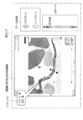
- FIG. 3 is a diagram illustrating an example of a three-dimensional superimposed image displayed on the display unit by the plaque emphasis display function of the medical image diagnostic apparatus according to the present embodiment.
- FIG. 4 is a diagram illustrating an example of a two-dimensional superimposed image displayed on the display unit by the plaque emphasis display function of the medical image diagnostic apparatus according to the present embodiment.
- FIG. 1 is a block diagram showing an example of the configuration of the medical image diagnostic apparatus 1 according to the present embodiment.
- the medical image diagnostic apparatus 1 includes a communication interface unit 11, a storage unit 12, a control unit 13, an input unit 14, a reconstruction unit 15, and a coronary artery analysis unit 16 (extraction unit 16).
- the medical image diagnostic apparatus 1 includes a CT apparatus, a SPECT apparatus, a PET apparatus, a PACS (Picture Archiving and Communication System: medical image information) via a network such as a LAN (Local Area Network) or a public electronic communication line. System).
- a network such as a LAN (Local Area Network) or a public electronic communication line. System).
- the medical image diagnostic apparatus 1 includes a communication interface unit 11 for connecting to an external apparatus via a network.
- the communication interface unit 11 includes, for example, a connector unit (not shown) for connecting to an external device or the like with a wired cable, a wireless signal receiving unit (not shown) for receiving a radio signal from the external device, etc.
- a connector unit not shown
- a wireless signal receiving unit not shown
- the medical diagnostic imaging apparatus 1 transmits / receives data to / from an external device via the communication interface unit 11 according to control of the control unit 13 described later.
- the storage unit 12 is a semiconductor storage device such as a flash SSD (Solid State Disk) that is a semiconductor storage element, an HDD (Hard Disk Drive), or the like.
- the storage unit 12 stores data of an image to be processed by the medical image diagnostic apparatus 1 transmitted from the external device according to control by the control unit 13.
- the image data to be processed is a series of image data obtained by continuously and repeatedly imaging a coronary artery with a tracer over one cycle of heartbeat.
- the series of image data is typically time-series CT volume data constituting one cycle of heartbeat collected by the CT apparatus.
- the storage unit 12 may store the above-described image data received and stored via the communication interface unit 11 as it is, or when the user operation of the medical image diagnostic apparatus 1 is completed. May be deleted. That is, the storage unit 12 may merely function as a memory that temporarily stores the above-described image data received via the communication interface unit 11 in the medical image diagnostic apparatus 1.
- the storage unit 12 stores data related to a CT value correspondence table in which a plurality of CT value data is associated with each of index data indicating a plurality of plaque hardnesses.
- the index indicating the hardness of the plaque is, for example, the hardness (hardness) of the plaque.
- an index indicating the hardness of the plaque is referred to as the hardness of the plaque.
- the storage unit 12 stores data relating to a risk correspondence table in which a plurality of stress value data and a plurality of plaque hardness data are respectively associated with a plurality of peeling risk data.
- the risk correspondence table may be provided for each subject information, each part, and each small range of the part.
- the subject information is, for example, the age of the subject, the weight of the subject, and the sex of the subject.
- Each part includes the heart and the brain.
- the control unit 13 includes a CPU (Central Processing Unit) and a memory circuit.
- the control unit 13 receives the information input from the input unit 14 and temporarily stores the input information in the memory circuit.
- the control unit 13 controls each unit of the medical image diagnostic apparatus 1 based on the input information.
- the control unit 13 collectively controls writing processing of data generated or received in each unit to the storage unit 12 and data reading processing from the storage unit 12 to each unit.
- the input unit 14 functions as an interface for receiving instruction information from the user to the medical image diagnostic apparatus 1.
- input devices such as a mouse, a keyboard, a trackball, a touch panel, and buttons can be used as appropriate.
- the input unit 14 receives an input of a cross-sectional image of a coronary artery desired by the user.
- the input unit 14 receives a desired coronary artery according to a user operation on a three-dimensional CT image related to the coronary artery displayed on the display unit 23 described later, for example.
- the reconstruction unit 15 reconstructs a three-dimensional or two-dimensional CT image related to the coronary artery based on CT (Computed Tomography) volume data.
- CT Computer Tomography
- the three-dimensional and two-dimensional CT images related to the coronary artery are simply referred to as CT images related to the coronary artery.
- the coronary artery analysis unit 16 calculates a plurality of stress values corresponding to a plurality of regions constituting the coronary artery based on the temporal displacement amount of the coronary artery due to the heartbeat identified from the time series CT volume data constituting one cycle of the heartbeat. calculate.
- the coronary artery analysis unit 16 may calculate a change in stress value or a difference in stress value instead of the stress value in each region of the coronary artery.
- the change in stress value refers to a change in stress value related to the same region in the preceding and following time phases.
- the difference in stress value refers to a difference in stress value with respect to a preset threshold value, a difference from a stress value corresponding to a region designated by the user on the superimposed image displayed on the display unit 23, or the like. Point to. Then, a stress value distribution diagram corresponding to the CT image is generated. The detailed description of the coronary artery analysis unit 16 will be described later.
- the plaque position estimation unit 17 estimates the plaque position on the CT image related to the coronary artery. For the estimation of the plaque position, for example, a change in the inner diameter of the coronary artery is used. The inner diameter is defined by a length perpendicular to the core line of the coronary artery in the coronary artery. The plaque position estimation unit 17 calculates the size of the inner diameter at a plurality of points of the coronary artery. The position of the coronary artery in which the size of the inner diameter suddenly narrows is estimated as the plaque position.
- the color map conversion unit 18 converts the stress value distribution map generated by the coronary artery analysis unit 16 into a stress value color map based on a LUT (Look Up Table) relating to stress values stored in the storage unit 12 in advance.
- the stress value LUT is a correspondence table in which a plurality of pieces of color information are assigned to data related to a plurality of stress values.
- the hardness estimation unit 19 estimates the hardness of the plaque based on the CT value of the plaque position estimated by the plaque position estimation unit 17. Specifically, the hardness estimation unit 19 reads the data of the CT value correspondence table stored in the storage unit 12. Then, the hardness estimation unit 19 estimates the hardness of the target plaque by referring to the CT value correspondence table and comparing the CT value of the target plaque with a plurality of CT values in the CT correspondence table.
- the plaque map generation unit 20 generates a plaque map in which color information corresponding to the hardness of the plaque is added to the mark representing the plaque on the CT image related to the coronary artery.
- the color information only needs to be identified according to the hardness of the plaque, and includes, for example, the type of color and the color density. Further, the plaque map generation unit 20 may change the shape of the mark representing the plaque according to the hardness of the plaque.
- the risk evaluation unit 21 determines the plaque based on the hardness of the plaque and the stress value. Assess the risk. Specifically, the risk evaluation unit 21 reads data of the risk correspondence table stored in the storage unit 12.
- the risk evaluation unit 21 refers to the risk correspondence table, and identifies the target plaque peeling risk based on the stress value of the region corresponding to the position of the target plaque and the hardness of the target plaque.
- the hardness may be, for example, a numerical value or a frequency.
- the risk evaluation unit 21 calculates a risk value based on the hardness and stress value of the plaque.
- the danger value is obtained, for example, by multiplying a value indicating the hardness of the plaque by a stress value in a region corresponding to the plaque position. Then, the risk level of the plaque is evaluated according to the calculated risk value.
- the risk evaluation unit 21 evaluates the risk according to the calculated risk value and the range of the risk value assigned to each stage.
- the risk evaluation unit 21 may calculate the risk value by multiplying the CT value corresponding to the position of the target plaque by the stress value of the region corresponding to the position of the target plaque.
- the setting of the risk level can be appropriately changed according to the user instruction.
- the annotation generation unit 22 generates an annotation for emphasizing a high-risk plaque.
- the annotation includes, for example, text information related to the plaque risk evaluation result or graphic information corresponding to the plaque risk evaluation result.
- the text information may be, for example, information for notifying the user of the peeling risk such as “no risk”, “high risk”, “no treatment needed”, “treatment required”, etc. It may be information for notifying the user of the necessity of treatment.
- the annotation generator 22 determines the necessity of treatment according to the degree of peeling risk.
- the graphic information is, for example, a mark such as a flag, a circle, a rectangle, and a star.
- the display unit 23 displays a superimposed image in which a plaque map and a stress value color map are superimposed on a CT image.
- the display unit 23 displays the annotation generated by the annotation generation unit 22 so that the target plaque position on the above-described superimposed image can be recognized.
- the display unit 23 displays the annotation so that the position on the image indicated by the annotation corresponds to the position of the plaque.
- the display unit 23 switches the display of the CT image, the plaque map, the stress value color map, and the superimposed image according to the user instruction via the input unit 14 according to the user instruction via the input unit 14.
- plaque highlighting function In the plaque emphasis display function, the display unit 23 of the medical image diagnostic apparatus 1 according to the present embodiment emphasizes a plaque with a high degree of risk on a superimposed image in which a plaque map and a stress value map are superimposed on a CT image. It is a function to display.
- processing according to the plaque highlighting function hereinafter referred to as plaque highlighting processing
- FIG. 1 Processing according to the plaque highlighting function
- FIG. 2 is a flowchart for explaining the plaque emphasis display process included in the medical image diagnostic apparatus 1 according to the present embodiment.
- time series CT volume data constituting one cycle of heartbeat of the coronary artery is received from an external device via the communication interface unit 11 (step S11).
- the received CT volume data is stored in the storage unit 12.
- the coronary artery analysis unit 16 Based on the CT volume data, the coronary artery analysis unit 16 extracts the blood vessel core line of the coronary artery and information related to the anatomical structure of the coronary artery such as the inner wall of the blood vessel (step S12). Based on the extracted anatomical structure of the coronary artery and physical parameters such as the viscosity value of blood flowing through the coronary artery, the coronary artery analysis unit 16 performs structural fluid analysis on the stress value of each of a plurality of regions constituting the coronary artery. It is executed (step S13). Then, a stress value distribution diagram is generated by the coronary artery analysis unit 16 (step S14). The color map converter 18 converts the stress value distribution map into a stress value color map (step S15).
- the plaque position estimation unit 17 estimates the plaque position on the CT image related to the coronary artery (step S16). Based on the CT value of the plaque position estimated by the plaque position estimation unit 17, the hardness estimation unit 19 estimates the hardness of the plaque (step S17). Then, the plaque map generator 20 generates a plaque map in which color information corresponding to the hardness of the plaque is added to the mark representing the plaque on the CT image related to the coronary artery (step S18).
- the risk of plaque peeling is evaluated by the risk evaluation unit (step S19).
- the annotation generator 22 generates an annotation for emphasizing the high-risk plaque (step S20).
- the display unit 23 displays a superimposed image obtained by superimposing a plaque map and a stress value color map and an annotation on the CT image (step S21).
- FIG. 3 is a diagram illustrating an example of a three-dimensional superimposed image displayed on the display unit 23 by the plaque highlighting function of the medical image diagnostic apparatus 1 according to the present embodiment.
- a superimposed image, a color bar, and a plurality of annotations in which a three-dimensional plaque map and a stress value color map are superimposed are displayed on a three-dimensional CT image related to the coronary artery.
- the CT image, the superimposed image, the plaque map, and the stress value color map can be appropriately switched according to a user instruction via the input unit 14.
- An icon for switching these images may be displayed in the display area.
- the color bar is an LUT used by the color map conversion unit 18 to convert the stress value distribution chart into a stress value color map. As shown in FIG.
- the plaque included in each of the three blood vessel regions indicates that the risk evaluation unit 21 determines that the risk is high.
- the annotation includes text information related to plaque properties (hardness) and stress values.
- the annotation 1 indicates that the plaque is hard and the stress value applied to the plaque is large.
- Annotation 3 indicates that the plaque is soft and the stress value is medium. The criterion for determining the peeling risk by the risk evaluation unit 21 can be appropriately changed according to a user instruction.
- FIG. 4 is a diagram illustrating an example of a two-dimensional superimposed image displayed on the display unit 23 by the plaque highlighting function of the medical image diagnostic apparatus 1 according to the present embodiment.
- a superimposed image obtained by superimposing a plaque map and a stress value color map on a CT image related to a coronary artery, a color bar, an annotation, and a plaque correspondence table are displayed.
- the stress value color map only needs to know the stress value applied to the blood vessel wall.
- the stress value color map is displayed in alignment with the CT image. Therefore, a mark indicating the magnitude of the stress value is displayed on the blood vessel wall along the blood vessel contour.
- the plaque correspondence table is for notifying the user of the hardness of the plaque.
- a color corresponding to the hardness of the plaque is displayed.
- the hardness of the plaque is represented by two stages, but may be represented by other plural stages.
- the color bar is displayed on the basis of the LUT used for converting the stress value distribution map into the stress value color map by the color map conversion unit 18, and expresses the magnitude of the stress value in color.
- the annotation indicates the position of the plaque, and includes text information for notifying the user of the plaque property and the stress value applied to the plaque position. Since this notification is only required to notify the user of the plaque peeling risk, the text information may be text information directly representing the peeling risk such as a peeling risk “high”. In addition, when a plurality of plaques have a high degree of peeling risk, the text information may include information such as a ranking of the peeling risk level of the plurality of plaques and a priority order of treatment.
- the stress value color map display method, plaque position display method, plaque property display method, and annotation display method shown in FIGS. 3 and 4 are examples.
- the display method is not limited to the above as long as the user can display a superimposed image in which the stress value color map and the plaque map are overlapped and display a high-risk plaque.
- the plaque emphasis display function described above the following effects can be obtained.
- the medical image diagnostic apparatus 1 according to the present embodiment having the plaque highlighting function for example, based on time-series CT volume data constituting one cycle of heartbeat of a coronary artery collected by a CT apparatus or the like, A map and a stress value color map can be generated. Then, a superimposed image in which the stress value color map is superimposed on the plaque map can be displayed. Then, plaque with a high degree of risk can be highlighted and displayed on the superimposed image or the like.
- the risk level can be automatically determined by the risk level evaluation unit 21 based on the hardness of the plaque and the stress value applied to the blood vessel where the plaque is located. Therefore, the degree of risk of the plaque can be estimated in consideration of not only the properties of the plaque but also the stress value applied to the plaque.
- the medical image diagnostic apparatus 1 describes the storage unit 12 as a component as shown in FIG.
- the image data to be processed may be stored in another modality, PACS, or the like connected to the medical image diagnostic apparatus 1 via the communication interface unit 11, and the medical image diagnostic apparatus 1
- the storage unit 12 may function as a memory that temporarily stores image data to be processed.
- SYMBOLS 1 Medical diagnostic imaging apparatus, 11 ... Communication interface part, 12 ... Memory
Landscapes
- Health & Medical Sciences (AREA)
- Life Sciences & Earth Sciences (AREA)
- Medical Informatics (AREA)
- Engineering & Computer Science (AREA)
- Nuclear Medicine, Radiotherapy & Molecular Imaging (AREA)
- Surgery (AREA)
- Veterinary Medicine (AREA)
- Biophysics (AREA)
- High Energy & Nuclear Physics (AREA)
- Public Health (AREA)
- General Health & Medical Sciences (AREA)
- Optics & Photonics (AREA)
- Pathology (AREA)
- Radiology & Medical Imaging (AREA)
- Biomedical Technology (AREA)
- Heart & Thoracic Surgery (AREA)
- Molecular Biology (AREA)
- Physics & Mathematics (AREA)
- Animal Behavior & Ethology (AREA)
- Vascular Medicine (AREA)
- Dentistry (AREA)
- Oral & Maxillofacial Surgery (AREA)
- Apparatus For Radiation Diagnosis (AREA)
Abstract
危険度の高いプラークを推定できる。 プラーク位置推定部17と硬さ推定部19とは、造影剤により血管が強調された時系列を構成する複数のCT画像のデータに基づいて、それぞれ血管におけるプラークの位置とプラークの硬さを示す指標とを推定する。抽出部16は、CT画像から血管を構成する複数の領域を抽出する。特定部21は、血管を構成する複数の領域の心拍動によるそれぞれの時間変位量に基づいて、血管を構成する複数の領域にそれぞれ対応する複数の応力値を特定し、プラークの硬さを示す指標とプラーク位置に対応する領域の応力値とに基づいて、プラークの剥離危険度を特定する。
Description
本発明の実施形態は、医用画像診断装置に関する。
脳梗塞や心筋梗塞などの、いわゆる血栓症が原因の死亡者は、依然として多い。心筋梗塞の原因の1つとしてプラークの剥離がある。プラークとは、冠動脈の血管の内膜にコレステロール脂肪などの物質と血中にあるマクロファージとが沈着したものである。プラークが内圧などにより剥離すると、剥離した箇所に血栓ができ、血栓が血流に乗って流れ、冠動脈を閉塞することにより、心筋梗塞が発生する。したがって、心筋梗塞を予防するためには、剥離する可能性の高いプラークをカテーテル手術等により除去する必要がある。カテーテル手術が必要かの判断には、プレッシャーワイヤーを用いたFFR(Functional Flow Reserve:心筋部分血流予備量)の測定結果等が用いられる。しかし、FFRの測定はプレッシャーワイヤーを挿入する必要があるため、患者への負担が大きい。そのため、カテーテル手術が必要かの判断を、患者への負担が小さて済むような方法で出来ることが望まれている。
現在、患者への負担が小さくて済むように、CT(Computed Tomography:コンピュータ断層撮影)装置により撮影されたCT画像のCT値に基づいて、プラーク性状を推定する技術がある。しかしながら、そのプラークが剥離する可能性の高い危険度の高いプラークかどうかを判定することは難しい。
危険度の高いプラークを推定できる医用画像診断装置を提供することにある。
本実施形態による医用画像診断装置は、造影剤により血管が強調された時系列を構成する複数のCT画像のデータに基づいて、前記血管におけるプラークの位置と前記プラークの硬さを示す指標とを推定する推定部と、前記CT画像から血管を構成する複数の領域を抽出する抽出部と、前記血管を構成する複数の領域の心拍動によるそれぞれの時間変位量に基づいて、前記血管を構成する複数の領域にそれぞれ対応する複数の応力値を特定し、前記プラークの硬さを示す指標と前記プラーク位置に対応する領域の応力値とに基づいて、前記プラークの剥離危険度を特定する特定部と、を具備することを特徴とする。
危険度の高いプラークを推定できる。
以下、図面を参照しながら本実施形態に係る医用画像診断装置1を説明する。なお、以下の説明において、略同一の機能及び構成を有する構成要素については、同一符号を付し、重複説明は必要な場合にのみ行う。
図1は、本実施形態に係る医用画像診断装置1の構成の一例を示すブロック図である。図1に示すように、医用画像診断装置1は、通信インターフェース部11と、記憶部12と、制御部13と、入力部14と、再構成部15と、冠動脈解析部16(抽出部16)と、プラーク位置推定部17と、カラーマップ変換部18と、硬さ推定部19と、プラークマップ発生部20と、危険度評価部21(特定部21)と、アノテーション発生部22と、表示部23と、を有する。
本実施形態に係る医用画像診断装置1は、LAN(Local Area Network)や公衆電子通信回線等のネットワークを介して、CT装置、SPECT装置、PET装置、PACS(Picture Archiving and Communication System:医療画像情報システム)等の外部装置に接続される。
本医用画像診断装置1は、ネットワークを介して外部装置に接続するための通信インターフェース部11を有する。通信インターフェース部11は、例えば、外部装置等と有線ケーブル等で接続されるためのコネクタ部(図示せず)及び外部装置からの無線信号を受信するための無線信号受信部(図示せず)等を有する。本医用画像診断装置1は、後述の制御部13の制御に従って、外部装置と通信インターフェース部11を介したデータの送受を行う。
記憶部12は、半導体記憶素子であるFlash SSD(Solid State Disk)などの半導体記憶装置及びHDD(Hard Disk Drive)等である。記憶部12は、制御部13による制御に従って、外部装置から送信された本医用画像診断装置1で処理対象となる画像のデータを記憶する。処理対象の画像のデータとは、トレーサーにより冠動脈を造影して心拍動の1サイクルにわたり、連続的に繰り返し撮影された一連の画像のデータである。一連の画像のデータは典型的にはCT装置により収集された心拍動の1サイクルを構成する時系列のCTボリュームデータである。なお、記憶部12は、通信インターフェース部11を介して受信し、記憶した上述の画像のデータを、そのまま保持していてもよいし、本医用画像診断装置1のユーザ操作が終了したのを契機に消去されてもよい。すなわち、記憶部12は、本医用画像診断装置1において、通信インターフェース部11を介して受信した上述の画像のデータを一時的に記憶するメモリとして機能するだけでもよい。
また、記憶部12は、複数のプラークの硬さを示す指標のデータに対して、それぞれ複数のCT値のデータを対応付けたCT値対応表に関するデータを記憶する。プラークの硬さを示す指標とは、例えば、プラークの硬さ(硬度)等である。以下、説明を簡単にするため、プラークの硬さを示す指標をプラークの硬さと呼ぶ。
また、記憶部12は、複数の剥離危険度を示すデータに対して、それぞれ複数の応力値のデータと複数のプラークの硬さのデータとを対応させた危険度対応表に関するデータを記憶する。なお、危険度対応表は、被検体情報毎、部位毎、及び部位の細かい範囲毎に設けられていても良い。被検体情報とは、例えば、被検体の年齢、被検体の体重、及び被検体の性別等である。部位毎とは、心臓と脳等である。
制御部13は、CPU(Central Processing Unit)とメモリ回路等を有する。制御部13は、入力部14から入力された情報を受け取り、一時的にメモリ回路に入力情報を記憶する。制御部13は、入力情報に基づいて本医用画像診断装置1の各部を制御する。また、制御部13は、各部で発生又は受信したデータの記憶部12への書き込み処理及び記憶部12から各部へのデータの読み出し処理を一括して制御する。
入力部14は、本医用画像診断装置1に対して、ユーザによる指示情報を受け付けるための、インターフェースとして機能する。入力部14には、マウス、キーボード、トラックボール、タッチパネル、及びボタン等の入力デバイスが適宜利用可能である。具体的には、入力部14は、ユーザが所望する冠動脈の断面画像の入力を受け付ける。入力部14は、所望する冠動脈を、例えば、後述の表示部23に表示された冠動脈に関する3次元のCT画像上のユーザ操作に従って受け付ける。
再構成部15は、CT(Computed Tomography:コンピュータ断層撮影)ボリュームデータに基づいて、冠動脈に関する3次元又は2次元のCT画像を再構成する。以下、冠動脈に関する3次元及び2次元のCT画像を単に冠動脈に関するCT画像と呼ぶ。
冠動脈解析部16は、心拍動の1サイクルを構成する時系列のCTボリュームデータから特定した心拍動による冠動脈の時間変位量に基づいて、冠動脈を構成する複数の領域に対応する複数の応力値を計算する。なお、冠動脈解析部16は、冠動脈の各領域における応力値に代わり、応力値の変化、または、応力値の差を計算してもよい。応力値の変化とは、前後の時相における、同じ領域に関する応力値の変化を指す。また、応力値の差とは、予め設定された閾値に対する応力値の差、または、表示部23に表示された重畳画像上で、ユーザに指定された領域に対応する応力値との差等を指す。そして、CT画像に対応する応力値分布図を発生する。冠動脈解析部16の詳細説明は後述する。
プラーク位置推定部17は、冠動脈に関するCT画像上のプラーク位置を推定する。プラーク位置の推定には、例えば、冠動脈の内径の大きさの変化が利用される。内径は冠動脈内の冠動脈の芯線に直交する長さで定義される。プラーク位置推定部17は、冠動脈の複数の点における内径の大きさを計算する。そして、内径の大きさが急に狭くなる冠動脈の位置を、プラークの位置と推定する。
カラーマップ変換部18は、冠動脈解析部16により発生された応力値分布図を、予め記憶部12に記憶された応力値に関するLUT(Look Up Table)に基づいて、応力値カラーマップに変換する。応力値のLUTとは、複数の応力値に関するデータに対して、それぞれ複数のカラー情報を割り当てた対応表である。
硬さ推定部19は、プラーク位置推定部17により推定されたプラークの位置のCT値に基づいて、そのプラークの硬さを推定する。具体的には、硬さ推定部19は、記憶部12に記憶されているCT値対応表のデータを読み出す。そして、硬さ推定部19は、CT値対応表を参照し、対象プラークのCT値をCT対応表における複数のCT値と比較することで、対象プラークの硬さを推定する。
プラークマップ発生部20は、冠動脈に関するCT画像上のプラークを表すマークに、プラークの硬さに応じた色情報を付加したプラークマップを発生する。色情報は、プラークの硬さに応じて、識別できればよく、例えば、色の種類及び色の濃淡等を含む。さらに、プラークマップ発生部20は、プラークの硬さに応じて、プラークを表すマークの形状を、変更してもよい
危険度評価部21は、プラークの硬さと応力値とに基づいて、プラークの危険度を評価する。具体的には、危険度評価部21は、記憶部12に記憶されている危険度対応表のデータを読み出す。そして、危険度評価部21は、危険度対応表を参照し、対象プラークの位置に対応する領域の応力値と、対象プラークの硬さとに基づいて、対象プラークの剥離危険度を特定する。ここにおける、硬さとは、例えば、数値であってもよいし、度数であってもよい。なお、危険度評価部21は、プラークの硬さと応力値とに基づいて、危険値を計算する。危険値とは、例えば、プラークの硬さを示す値に対して、プラークの位置に対応する領域の応力値を乗算することにより求められる。そして、計算した危険値に応じて、そのプラークの危険度を評価する。例えば、危険度が3段階、「危険度なし」、「危険度小」、「危険度大」で表されている場合において、各段階に対して、各段階で評価される危険値の範囲が割り当てられている。そして、危険度評価部21は、計算した危険値と、各段階に対して割り当てた危険値の範囲とに従って、危険度を評価する。なお、危険度評価部21は、対象プラークの位置に対応するCT値に対して、対象プラークの位置に対応する領域の応力値を乗算することにより、危険値を計算してもよい。なお、危険度の設定はユーザ指示に従って適宜変更が可能である。
危険度評価部21は、プラークの硬さと応力値とに基づいて、プラークの危険度を評価する。具体的には、危険度評価部21は、記憶部12に記憶されている危険度対応表のデータを読み出す。そして、危険度評価部21は、危険度対応表を参照し、対象プラークの位置に対応する領域の応力値と、対象プラークの硬さとに基づいて、対象プラークの剥離危険度を特定する。ここにおける、硬さとは、例えば、数値であってもよいし、度数であってもよい。なお、危険度評価部21は、プラークの硬さと応力値とに基づいて、危険値を計算する。危険値とは、例えば、プラークの硬さを示す値に対して、プラークの位置に対応する領域の応力値を乗算することにより求められる。そして、計算した危険値に応じて、そのプラークの危険度を評価する。例えば、危険度が3段階、「危険度なし」、「危険度小」、「危険度大」で表されている場合において、各段階に対して、各段階で評価される危険値の範囲が割り当てられている。そして、危険度評価部21は、計算した危険値と、各段階に対して割り当てた危険値の範囲とに従って、危険度を評価する。なお、危険度評価部21は、対象プラークの位置に対応するCT値に対して、対象プラークの位置に対応する領域の応力値を乗算することにより、危険値を計算してもよい。なお、危険度の設定はユーザ指示に従って適宜変更が可能である。
アノテーション発生部22は、危険度の高いプラークを強調するためのアノテーションを発生する。アノテーションには、例えば、プラークの危険度評価結果に関するテキスト情報又はプラークの危険度評価結果に応じたグラフィック情報が含まれる。テキスト情報とは、例えば、「危険度なし」、「危険度大」等の剥離危険度をユーザに通知するための情報であってもよいし、「治療の必要なし」、「要治療」等の治療の要否をユーザに通知するための情報であってもよい。この時、アノテーション発生部22は、剥離危険度に応じて、治療の要否を決定する。グラフィック情報とは、例えば、フラグ、円、矩形、及び星等のマークである。
表示部23は、CT画像に対して、プラークマップと応力値カラーマップとを重ねた重畳画像を表示する。また、表示部23は、アノテーション発生部22で発生されたアノテーションを上述の重畳画像上の対象プラーク位置がわかるように重ねて表示する。対象プラーク位置がわかるようにとは、例えば、表示部23は、アノテーションで指す画像上の位置をプラークの位置に対応するようにアノテーションを表示する。なお、入力部14を介したユーザ指示に従って、表示部23は、CT画像、プラークマップ、応力値カラーマップ、及び重畳画像との表示を、入力部14を介したユーザ指示に従って切り替える。
(プラーク強調表示機能)
プラーク強調表示機能は、本実施形態に係る医用画像診断装置1の表示部23が、CT画像に対して、プラークマップと応力値マップとを重ねた重畳画像上に、危険度の高いプラークを強調して表示する機能である。以下、プラーク強調表示機能に従う処理(以下、プラーク強調表示処理と呼ぶ)について、図2を参照して説明する。
プラーク強調表示機能は、本実施形態に係る医用画像診断装置1の表示部23が、CT画像に対して、プラークマップと応力値マップとを重ねた重畳画像上に、危険度の高いプラークを強調して表示する機能である。以下、プラーク強調表示機能に従う処理(以下、プラーク強調表示処理と呼ぶ)について、図2を参照して説明する。
図2は、本実施形態に係る医用画像診断装置1が備えるプラーク強調表示処理を説明するためのフローチャートである。まず、外部装置から、通信インターフェース部11を介して、冠動脈の心拍動の1サイクルを構成する時系列のCTボリュームデータを受信する(ステップS11)。受信したCTボリュームデータは記憶部12に記憶される。
CTボリュームデータに基づいて、冠動脈解析部16により、冠動脈の血管芯線と血管内壁等の冠動脈の解剖学的構造に関する情報とが抽出される(ステップS12)。抽出された冠動脈の解剖学的構造と冠動脈を流れる血液などの持つ粘性値などの物理パラメータとに基づいて、冠動脈解析部16により、冠動脈を構成する複数の領域各々の応力値に関する構造流体解析が実行される(ステップS13)。そして、冠動脈解析部16により応力値分布図が発生する(ステップS14)。カラーマップ変換部18により、応力値分布図が応力値カラーマップに変換される(ステップS15)。
ボリュームデータに基づいて、プラーク位置推定部17により、冠動脈に関するCT画像上のプラーク位置が推定される(ステップS16)。プラーク位置推定部17により推定されたプラークの位置のCT値に基づいて、硬さ推定部19により、そのプラークの硬さが推定される(ステップS17)。そして、プラークマップ発生部20により、冠動脈に関するCT画像上のプラークを表すマークに、プラークの硬さに応じた色情報を付加したプラークマップが発生される(ステップS18)。
プラークの硬さと応力値とに基づいて、危険等評価部により、プラークの剥離危険度が評価される(ステップS19)。評価された結果、危険度の高いプラークがCT画像上にある場合において、アノテーション発生部22は、危険度の高いプラークを強調するためのアノテーションを発生する(ステップS20)。そして、表示部23は、CT画像に対して、プラークマップと応力値カラーマップとを重ねた重畳画像とアノテーションとを表示する(ステップS21)。
ステップS20にて、表示部23に表示される重畳画像とアノテーションとの一例について図3と図4を参照して説明する。
図3は、本実施形態に係る医用画像診断装置1のプラーク強調表示機能により、表示部23に表示される3次元の重畳画像の一例を示した図である。図3には、冠動脈に関する3次元のCT画像に対して、3次元のプラークマップと応力値カラーマップとを重ねた重畳画像、カラーバー、及び複数のアノテーションとが表示されている。CT画像、重畳画像、プラークマップ、及び応力値カラーマップは、入力部14を介したユーザ指示に従って、適宜切り替え可能である。表示エリアに、これらの画像を切り替えるためのアイコンが表示されてもよい。カラーバーは、カラーマップ変換部18により、応力値分布図を応力値カラーマップに変換するために用いられたLUTである。図3に示すように、3つの血管領域がアノテーションにより強調されている。そのため、3つの血管領域のそれぞれに含まれるプラークは、危険度評価部21により、危険度が高いと判定されたことを示している。アノテーションには、プラーク性状(硬さ)と応力値とに関するテキスト情報が含まれている。例えば、アノテーション1は、プラークが硬く、そのプラークにかかる応力値が大きいことを示している。また、アノテーション3は、プラークが柔らかく、応力値は中ぐらいであることを示している。危険度評価部21による剥離危険度の判定基準は、ユーザ指示に従って、適宜変更が可能である。
図4は、本実施形態に係る医用画像診断装置1のプラーク強調表示機能により、表示部23に表示される2次元の重畳画像の一例を示した図である。図4には、冠動脈に関するCT画像に対してプラークマップと応力値カラーマップとを重ねた重畳画像と、カラーバーと、アノテーションと、プラーク対応表とが表示されている。
応力値カラーマップは、血管壁にかかる応力値が分かればよく、例えば、図4に示すように、応力値カラーマップはCT画像に対して、位置整合して表示される。そのため、血管輪郭に沿った血管壁に応力値の大きさを表すマークが表示される。プラーク対応表は、プラークの硬さをユーザに通知するためのものであり、例えば、図4に示すように、プラークの硬さと対応する色が表示される。また、図4では、2段階でプラークの硬さを表しているが、他の複数の段階で示しても良い。カラーバーは、カラーマップ変換部18により、応力値分布図を応力値カラーマップに変換するために用いられたLUTに基づいて表示され、応力値の大きさを色で表現するためのものである。また、アノテーションは、プラークの位置を指し、プラークの性状とプラークの位置にかかる応力値とを、ユーザに通知するためのテキスト情報を含む。この通知は、ユーザに、プラークの剥離危険度を通知するためのものであればよいため、テキスト情報は、剥離危険度「大」などの剥離危険度を直接表すテキスト情報であってもよい。また、複数のプラークの剥離危険度が高い場合、テキスト情報には、その複数のプラークの剥離危険度の順位、治療の優先順位等の情報が含まれていてもよい。
応力値カラーマップは、血管壁にかかる応力値が分かればよく、例えば、図4に示すように、応力値カラーマップはCT画像に対して、位置整合して表示される。そのため、血管輪郭に沿った血管壁に応力値の大きさを表すマークが表示される。プラーク対応表は、プラークの硬さをユーザに通知するためのものであり、例えば、図4に示すように、プラークの硬さと対応する色が表示される。また、図4では、2段階でプラークの硬さを表しているが、他の複数の段階で示しても良い。カラーバーは、カラーマップ変換部18により、応力値分布図を応力値カラーマップに変換するために用いられたLUTに基づいて表示され、応力値の大きさを色で表現するためのものである。また、アノテーションは、プラークの位置を指し、プラークの性状とプラークの位置にかかる応力値とを、ユーザに通知するためのテキスト情報を含む。この通知は、ユーザに、プラークの剥離危険度を通知するためのものであればよいため、テキスト情報は、剥離危険度「大」などの剥離危険度を直接表すテキスト情報であってもよい。また、複数のプラークの剥離危険度が高い場合、テキスト情報には、その複数のプラークの剥離危険度の順位、治療の優先順位等の情報が含まれていてもよい。
なお、図3と図4とでそれぞれ示した3次元重畳画像と2次元重畳画像とは、入力部14を介したユーザ指示に従って、切り替えが可能である。また、図3や図4で示した、応力値カラーマップの表示方法、プラーク位置の表示方法、プラーク性状の表示方法、及びアノテーションの表示方法は、一例である。ユーザが、応力値カラーマップとプラークマップとを重ねた重畳画像の表示及び危険度の高いプラークの表示が出来るのであれば、上述の表示方法に限定されない。
以上に述べたプラーク強調表示機能によれば、以下の効果を得ることができる。
プラーク強調表示機能を備える本実施形態に係る医用画像診断装置1によれば、例えば、CT装置等により収集された冠動脈の心拍動の1サイクルを構成する時系列のCTボリュームデータに基づいて、プラークマップと応力値カラーマップとを発生することができる。そして、プラークマップに対して、応力値カラーマップを重ねた重畳画像を表示することができる。そして、重畳画像上等で、危険度が高いプラークを強調して表示することができる。危険度は、プラークの硬さ及びプラークが位置する血管にかかる応力値等に基づいて、危険度評価部21により、自動的に判定することができる。したがって、プラークの性状だけではなく、そのプラークにかかる応力値を考慮した上で、そのプラークの危険度を推定することができる。
プラーク強調表示機能を備える本実施形態に係る医用画像診断装置1によれば、例えば、CT装置等により収集された冠動脈の心拍動の1サイクルを構成する時系列のCTボリュームデータに基づいて、プラークマップと応力値カラーマップとを発生することができる。そして、プラークマップに対して、応力値カラーマップを重ねた重畳画像を表示することができる。そして、重畳画像上等で、危険度が高いプラークを強調して表示することができる。危険度は、プラークの硬さ及びプラークが位置する血管にかかる応力値等に基づいて、危険度評価部21により、自動的に判定することができる。したがって、プラークの性状だけではなく、そのプラークにかかる応力値を考慮した上で、そのプラークの危険度を推定することができる。
本発明のいくつかの実施形態を説明したが、これらの実施形態は、例として提示したものであり、発明の範囲を限定することは意図していない。これら実施形態は、その他の様々な形態で実施されることが可能であり、発明の趣旨を逸脱しない範囲で、種々の省略、置き換え、変更を行なうことができる。例えば、本実施形態の医用画像診断装置1は、図1に示すように、記憶部12を構成要素として記載している。しかしながら、処理対象の画像のデータは、本医用画像診断装置1に、通信インターフェース部11を介して接続されている、他のモダリティやPACS等に記憶されていてもよく、本医用画像診断装置1の記憶部12は、一時的に処理対象の画像のデータを記憶するメモリとして機能してもよい。これら実施形態やその変形は、発明の範囲や趣旨に含まれると同様に、特許請求の範囲に記載された発明とその均等の範囲に含まれるものある。
1…医用画像診断装置、11…通信インターフェース部、12…記憶部、13…制御部、14…入力部、15…再構成部、16…冠動脈解析部(抽出部)、17…プラーク位置推定部、18…カラーマップ変換部、19…硬さ推定部、20…プラークマップ発生部、21…危険度評価部(特定部)、22…アノテーション発生部、23…表示部
Claims (7)
- 造影剤により血管が強調された時系列を構成する複数のCT画像のデータに基づいて、前記血管におけるプラークの位置を推定する推定部と、
前記CT画像から血管を構成する複数の領域を抽出する抽出部と、
前記血管を構成する複数の領域の心拍動によるそれぞれの時間変位量に基づいて、前記血管を構成する複数の領域にそれぞれ対応する複数の応力値を特定し、前記プラークの硬さを示す指標と前記プラークの位置に対応する領域の応力値とに基づいて、前記プラークの剥離危険度を特定する特定部と、
を具備することを特徴とする医用画像診断装置。 - 前記CT画像に対して、前記プラークの位置にプラークを表すマークと、前記応力値の分布図とを重ねて表示する表示部をさらに具備すること、
を特徴とする請求項1記載の医用画像診断装置。 - 前記応力値の分布図は、応力値に応じたカラーマップであること、
を特徴とする請求項2記載の医用画像診断装置。 - 前記表示部は、前記マークを、前記プラークに対応する硬さを示す指標に応じた色、または形状で表示すること、
を特徴とする請求項2記載の医用画像診断装置。 - 前記表示部は、前記マークを、前記プラークに対応する剥離危険度に応じた色、または、形状で表示すること、
を特徴とする請求項2記載の医用画像診断装置。 - 前記表示部は、前記マークのうち、剥離危険度の高いプラークに対応するマークを強調して表示すること、
を特徴とする請求項2記載の医用画像診断装置。 - 前記表示部は、前記マークを、前記マークに対応するプラークの硬さを示す指標と、前記マークの位置に対応する領域の応力値とに関するテキスト情報とともに表示すること、
を特徴とする請求項2記載の医用画像診断装置。
Priority Applications (2)
| Application Number | Priority Date | Filing Date | Title |
|---|---|---|---|
| CN201380003267.XA CN103957805A (zh) | 2012-11-30 | 2013-11-29 | 医用图像诊断装置 |
| US14/329,441 US11109829B2 (en) | 2012-11-30 | 2014-07-11 | Medical image diagnostic apparatus |
Applications Claiming Priority (2)
| Application Number | Priority Date | Filing Date | Title |
|---|---|---|---|
| JP2012-263417 | 2012-11-30 | ||
| JP2012263417A JP6017284B2 (ja) | 2012-11-30 | 2012-11-30 | 医用画像診断装置 |
Related Child Applications (1)
| Application Number | Title | Priority Date | Filing Date |
|---|---|---|---|
| US14/329,441 Continuation US11109829B2 (en) | 2012-11-30 | 2014-07-11 | Medical image diagnostic apparatus |
Publications (1)
| Publication Number | Publication Date |
|---|---|
| WO2014084366A1 true WO2014084366A1 (ja) | 2014-06-05 |
Family
ID=50827994
Family Applications (1)
| Application Number | Title | Priority Date | Filing Date |
|---|---|---|---|
| PCT/JP2013/082219 Ceased WO2014084366A1 (ja) | 2012-11-30 | 2013-11-29 | 医用画像診断装置 |
Country Status (4)
| Country | Link |
|---|---|
| US (1) | US11109829B2 (ja) |
| JP (1) | JP6017284B2 (ja) |
| CN (1) | CN103957805A (ja) |
| WO (1) | WO2014084366A1 (ja) |
Families Citing this family (9)
| Publication number | Priority date | Publication date | Assignee | Title |
|---|---|---|---|---|
| WO2014084398A1 (ja) | 2012-11-30 | 2014-06-05 | 株式会社 東芝 | 医用画像診断装置 |
| WO2014084382A1 (ja) * | 2012-11-30 | 2014-06-05 | 株式会社 東芝 | 医用画像処理装置 |
| JP6139116B2 (ja) | 2012-11-30 | 2017-05-31 | 東芝メディカルシステムズ株式会社 | 医用画像処理装置 |
| US9042613B2 (en) * | 2013-03-01 | 2015-05-26 | Heartflow, Inc. | Method and system for determining treatments by modifying patient-specific geometrical models |
| RU2017116859A (ru) * | 2014-10-13 | 2018-11-15 | Конинклейке Филипс Н.В. | Классификация состояния исследуемой ткани на основании лонгитудинальных признаков |
| US20170221204A1 (en) * | 2016-01-28 | 2017-08-03 | Siemens Medical Solutions Usa, Inc. | Overlay Of Findings On Image Data |
| US10779786B2 (en) | 2016-10-04 | 2020-09-22 | Canon Medical Systems Corporation | Medical information processing apparatus, X-ray CT apparatus, and medical information processing method |
| CN109949265B (zh) * | 2017-12-20 | 2023-10-03 | 东芝医疗系统株式会社 | 医用图像处理装置及医用图像处理方法 |
| US11189375B1 (en) * | 2020-05-27 | 2021-11-30 | GE Precision Healthcare LLC | Methods and systems for a medical image annotation tool |
Citations (2)
| Publication number | Priority date | Publication date | Assignee | Title |
|---|---|---|---|---|
| JP2009082407A (ja) * | 2007-09-28 | 2009-04-23 | Toshiba Corp | 画像処理装置及び医用画像処理装置 |
| US20120063663A1 (en) * | 2010-09-15 | 2012-03-15 | Toshiba Medical Systems Corporation | Medical image processing apparatus and medical image processing method |
Family Cites Families (17)
| Publication number | Priority date | Publication date | Assignee | Title |
|---|---|---|---|---|
| WO2001093745A2 (en) * | 2000-06-06 | 2001-12-13 | The Research Foundation Of State University Of New York | Computer aided visualization, fusion and treatment planning |
| US20040255957A1 (en) * | 2003-05-01 | 2004-12-23 | Robert Cafferata | Method and system for treating vulnerable plaque |
| US7306562B1 (en) * | 2004-04-23 | 2007-12-11 | Medical Software, Llc | Medical risk assessment method and program product |
| US20060036167A1 (en) * | 2004-07-03 | 2006-02-16 | Shina Systems Ltd. | Vascular image processing |
| US7860283B2 (en) * | 2006-10-25 | 2010-12-28 | Rcadia Medical Imaging Ltd. | Method and system for the presentation of blood vessel structures and identified pathologies |
| CN102172330B (zh) * | 2007-07-10 | 2013-03-27 | 株式会社东芝 | X射线摄影装置以及图像处理显示装置 |
| US20100017182A1 (en) * | 2008-07-15 | 2010-01-21 | Szilard Voros | Method for coronary artery disease risk assessment |
| US8885905B2 (en) * | 2009-12-03 | 2014-11-11 | Cedars-Sinai Medical Center | Method and system for plaque characterization |
| US8315812B2 (en) * | 2010-08-12 | 2012-11-20 | Heartflow, Inc. | Method and system for patient-specific modeling of blood flow |
| DE102011083704B4 (de) * | 2011-09-29 | 2025-12-31 | Siemens Healthineers Ag | Angiographisches Untersuchungsverfahren |
| BR112014031979A8 (pt) * | 2012-06-27 | 2021-02-23 | Koninklijke Philips Nv | sistema de ultrassom para diagnóstico que produz imagens do fluxo em cores da velocidade do fluxo ou movimento |
| CN104582572B (zh) | 2012-08-16 | 2018-04-13 | 东芝医疗系统株式会社 | 图像处理装置、医用图像诊断装置以及血压监视器 |
| WO2014084398A1 (ja) | 2012-11-30 | 2014-06-05 | 株式会社 東芝 | 医用画像診断装置 |
| JP5972768B2 (ja) | 2012-11-30 | 2016-08-17 | 東芝メディカルシステムズ株式会社 | 医用画像処理装置 |
| WO2014084382A1 (ja) | 2012-11-30 | 2014-06-05 | 株式会社 東芝 | 医用画像処理装置 |
| JP6139116B2 (ja) | 2012-11-30 | 2017-05-31 | 東芝メディカルシステムズ株式会社 | 医用画像処理装置 |
| JP6091870B2 (ja) | 2012-12-07 | 2017-03-08 | 東芝メディカルシステムズ株式会社 | 血管解析装置、医用画像診断装置、血管解析方法、及び血管解析プログラム |
-
2012
- 2012-11-30 JP JP2012263417A patent/JP6017284B2/ja active Active
-
2013
- 2013-11-29 WO PCT/JP2013/082219 patent/WO2014084366A1/ja not_active Ceased
- 2013-11-29 CN CN201380003267.XA patent/CN103957805A/zh active Pending
-
2014
- 2014-07-11 US US14/329,441 patent/US11109829B2/en active Active
Patent Citations (5)
| Publication number | Priority date | Publication date | Assignee | Title |
|---|---|---|---|---|
| JP2009082407A (ja) * | 2007-09-28 | 2009-04-23 | Toshiba Corp | 画像処理装置及び医用画像処理装置 |
| US20120063663A1 (en) * | 2010-09-15 | 2012-03-15 | Toshiba Medical Systems Corporation | Medical image processing apparatus and medical image processing method |
| EP2442276A1 (en) * | 2010-09-15 | 2012-04-18 | Kabushiki Kaisha Toshiba | Medical image processing apparatus and medical image processing method |
| CN102415898A (zh) * | 2010-09-15 | 2012-04-18 | 株式会社东芝 | 医用图像处理装置和医用图像处理方法 |
| JP2012081254A (ja) * | 2010-09-15 | 2012-04-26 | Toshiba Corp | 医用画像処理装置及び医用画像処理方法 |
Non-Patent Citations (3)
| Title |
|---|
| LI-NA PU: "A quantitative study of the effect of blood viscosity and bulk modulus of plaque compositions on the vulnerability of an atherosclerotic plaque using a 3D fluid-structure interaction model", BIOMEDICAL AND HEALTH INFORMATICS (BHI), 2012 IEEE -EMBS INTERNATIONAL CONFERENCE, 5 January 2012 (2012-01-05), pages 245 - 248 * |
| SALVUCCI, F.P. ET AL.: "A patient-specific method for the evaluation of wall shear stress in human coronary arteries", ENGINEERING IN MEDICINE AND BIOLOGY SOCIETY (EMBC), 2010 ANNUAL INTERNATIONAL CONFERENCE OF THE IEEE, 31 August 2010 (2010-08-31), pages 3788 - 3791 * |
| TAEWON SEO ET AL.: "The blood flow simulations of human aortic arch model with major branches", BIOMEDICAL ENGINEERING AND INFORMATICS (BMEI), 2011 4TH INTERNATIONAL CONFERENCE, vol. 2, 15 October 2011 (2011-10-15), pages 923 - 926 * |
Also Published As
| Publication number | Publication date |
|---|---|
| US20140323858A1 (en) | 2014-10-30 |
| US11109829B2 (en) | 2021-09-07 |
| JP2014108199A (ja) | 2014-06-12 |
| JP6017284B2 (ja) | 2016-10-26 |
| CN103957805A (zh) | 2014-07-30 |
Similar Documents
| Publication | Publication Date | Title |
|---|---|---|
| JP6017284B2 (ja) | 医用画像診断装置 | |
| US20230017788A1 (en) | Medical image processing apparatus and medical image processing method | |
| US11694330B2 (en) | Medical image processing apparatus, system, and method | |
| CN109074870B (zh) | 用于对未分辨血管进行识别和建模的系统和方法 | |
| EP3308710B1 (en) | Blood vessel image processing apparatus, blood vessel image processing program, and blood vessel image processing method | |
| JP6262027B2 (ja) | 医用画像処理装置 | |
| EP3281135B1 (en) | System and method for vascular tree generation using patient-specific structural and functional data, and joint prior information | |
| CN102551780B (zh) | 用于确定和显示心肌的供血的装置和计算机断层造影仪 | |
| CN106163401B (zh) | 用于冠状血管的医学成像的设备和方法 | |
| US10898267B2 (en) | Mobile FFR simulation | |
| JP6751184B2 (ja) | 医用画像処理装置、医用画像処理システムおよび医用画像処理方法 | |
| WO2014084286A1 (ja) | 医用情報処理装置、医用画像診断装置及び医用情報処理方法 | |
| US10362943B2 (en) | Dynamic overlay of anatomy from angiography to fluoroscopy | |
| JP2020512871A (ja) | 標準化された冠動脈疾患メトリック | |
| JP2014100555A (ja) | 画像処理装置、医用画像診断装置及び画像処理プログラム | |
| JP5972768B2 (ja) | 医用画像処理装置 | |
| JP6125705B2 (ja) | 医用画像診断装置及び医用画像診断装置の作動方法 | |
| US20220280124A1 (en) | Diagnosis support system | |
| JP6871007B2 (ja) | 医用画像処理装置及び医用画像診断システム | |
| JP2014046109A (ja) | 医用画像処理装置 | |
| US12079986B2 (en) | Medical image processing apparatus, system, and method | |
| JP6530043B2 (ja) | 医用画像処理装置、医用画像処理方法および記録媒体 | |
| JP7783007B2 (ja) | 医用画像処理装置、医用画像処理方法及び医用画像処理プログラム | |
| JP6411072B2 (ja) | 医用画像処理装置、医用画像処理方法およびプログラム |
Legal Events
| Date | Code | Title | Description |
|---|---|---|---|
| 121 | Ep: the epo has been informed by wipo that ep was designated in this application |
Ref document number: 13858107 Country of ref document: EP Kind code of ref document: A1 |
|
| NENP | Non-entry into the national phase |
Ref country code: DE |
|
| 122 | Ep: pct application non-entry in european phase |
Ref document number: 13858107 Country of ref document: EP Kind code of ref document: A1 |