WO2014084028A1 - 移動通信システム、基地局、プロセッサ、及び通信制御方法 - Google Patents
移動通信システム、基地局、プロセッサ、及び通信制御方法 Download PDFInfo
- Publication number
- WO2014084028A1 WO2014084028A1 PCT/JP2013/080396 JP2013080396W WO2014084028A1 WO 2014084028 A1 WO2014084028 A1 WO 2014084028A1 JP 2013080396 W JP2013080396 W JP 2013080396W WO 2014084028 A1 WO2014084028 A1 WO 2014084028A1
- Authority
- WO
- WIPO (PCT)
- Prior art keywords
- communication
- cell
- handover
- support
- enb
- Prior art date
Links
Images


Classifications
-
- H—ELECTRICITY
- H04—ELECTRIC COMMUNICATION TECHNIQUE
- H04W—WIRELESS COMMUNICATION NETWORKS
- H04W36/00—Hand-off or reselection arrangements
- H04W36/34—Reselection control
- H04W36/38—Reselection control by fixed network equipment
-
- H—ELECTRICITY
- H04—ELECTRIC COMMUNICATION TECHNIQUE
- H04W—WIRELESS COMMUNICATION NETWORKS
- H04W36/00—Hand-off or reselection arrangements
- H04W36/08—Reselecting an access point
-
- H—ELECTRICITY
- H04—ELECTRIC COMMUNICATION TECHNIQUE
- H04W—WIRELESS COMMUNICATION NETWORKS
- H04W36/00—Hand-off or reselection arrangements
- H04W36/0005—Control or signalling for completing the hand-off
- H04W36/0009—Control or signalling for completing the hand-off for a plurality of users or terminals, e.g. group communication or moving wireless networks
-
- H—ELECTRICITY
- H04—ELECTRIC COMMUNICATION TECHNIQUE
- H04W—WIRELESS COMMUNICATION NETWORKS
- H04W36/00—Hand-off or reselection arrangements
- H04W36/0005—Control or signalling for completing the hand-off
- H04W36/0055—Transmission or use of information for re-establishing the radio link
- H04W36/0061—Transmission or use of information for re-establishing the radio link of neighbour cell information
-
- H—ELECTRICITY
- H04—ELECTRIC COMMUNICATION TECHNIQUE
- H04W—WIRELESS COMMUNICATION NETWORKS
- H04W36/00—Hand-off or reselection arrangements
- H04W36/0005—Control or signalling for completing the hand-off
- H04W36/0055—Transmission or use of information for re-establishing the radio link
- H04W36/0072—Transmission or use of information for re-establishing the radio link of resource information of target access point
-
- H—ELECTRICITY
- H04—ELECTRIC COMMUNICATION TECHNIQUE
- H04W—WIRELESS COMMUNICATION NETWORKS
- H04W76/00—Connection management
- H04W76/20—Manipulation of established connections
- H04W76/23—Manipulation of direct-mode connections
-
- H—ELECTRICITY
- H04—ELECTRIC COMMUNICATION TECHNIQUE
- H04W—WIRELESS COMMUNICATION NETWORKS
- H04W36/00—Hand-off or reselection arrangements
- H04W36/03—Reselecting a link using a direct mode connection
Definitions
- the present invention relates to a mobile communication system, a base station, a processor, and a communication control method that support D2D communication.
- D2D communication is a communication mode in which a user terminal group including a plurality of adjacent user terminals performs communication without going through a core network within a frequency band assigned to a mobile communication system.
- the user terminal in D2D communication is in a state (connection state) where connection with the cell of the base station is established.
- not all cells in the mobile communication system support D2D communication. That is, a cell that supports D2D communication and a cell that does not support D2D communication may be mixed.
- D2D communication when a user terminal in D2D communication performs handover to a cell that does not support D2D communication, there is a problem that D2D communication cannot be continued (that is, D2D communication is interrupted).
- the present invention provides a mobile communication system, a base station, a processor, and a communication control method that can appropriately perform handover control for a user terminal in D2D communication.
- a mobile communication system includes a base station that configures a D2D support cell that supports D2D communication that is direct inter-terminal communication, and a user terminal that performs the D2D communication in the D2D support cell.
- the base station includes a control unit that controls handover of the user terminal. The control unit controls the handover based on a support status of the D2D communication in a handover target cell of the user terminal.
- the mobile communication system includes a base station configuring a D2D support cell that supports D2D communication that is direct inter-terminal communication, and a user terminal that performs the D2D communication in the D2D support cell.
- Direct communication between terminals refers to communication between terminals that does not pass through at least a core network.
- the base station includes a control unit that controls handover of the user terminal. The control unit controls the handover based on a support status of the D2D communication in a handover target cell of the user terminal. Thereby, even if a cell that supports D2D communication and a cell that does not support D2D communication coexist, handover can be appropriately controlled.
- the base station configures another D2D support cell that supports the D2D communication in addition to the D2D support cell.
- the control unit controls the user terminal to perform the handover while maintaining the D2D communication.
- a user terminal can perform a hand-over, maintaining D2D communication between the cells comprised by the same base station.
- the mobile communication system further includes an adjacent base station that configures an adjacent cell adjacent to the D2D support cell.
- the adjacent base station transmits D2D support information related to the support status of the D2D communication in the adjacent cell to the base station.
- the control unit controls the handover to the neighboring cell based on the D2D support information. Thereby, even if the cell to be handed over is a cell of an adjacent base station (adjacent cell), the handover can be appropriately controlled.
- the neighboring cell supports the D2D communication and supports the handover that maintains the D2D communication.
- the control unit controls the user terminal to perform the handover while maintaining the D2D communication.
- the user terminal can perform handover while maintaining D2D communication between cells configured by different base stations.
- the control unit includes information indicating that the user terminal is performing the D2D communication when it is determined that the handover is performed from the D2D support cell to the neighboring cell.
- a handover request is transmitted to the neighboring base station.
- the adjacent base station can determine whether or not to permit the handover request in consideration of the user terminal performing D2D communication. Also, the adjacent base station can make preparations such as securing radio resources for D2D communication.
- the neighboring base station when the neighboring base station grants the handover request, the neighboring base station transmits an authorization response including D2D allocation information related to allocation of the radio resource for D2D communication in the neighboring cell to the base station. . Accordingly, the base station can appropriately control the handover in consideration of whether or not the radio resource for D2D communication is allocated in the adjacent base station.
- the control unit receives the permission response from the adjacent base station, and when the D2D allocation information indicates that the radio resource for D2D communication cannot be allocated, the adjacent cell The handover for is canceled.
- the adjacent cell The handover for is canceled.
- the control unit receives the admission response from the adjacent base station, and when the frequency to which the D2D support cell belongs is different from the frequency to which the adjacent cell belongs, Instructs the user terminal to perform inter-frequency handover to the cell. Thereby, even if the frequency to which the D2D support cell belongs and the frequency to which the adjacent cell belongs are different, the user terminal can perform handover while maintaining D2D communication.
- the neighboring cell supports the D2D communication and does not support the handover that maintains the D2D communication.
- the control unit controls the user terminal to perform the handover after the D2D communication is stopped.
- the user terminal when the user terminal performs the handover to the neighboring cell and desires to resume the D2D communication, the user terminal notifies the neighboring cell that the D2D communication is to be performed. . Thereby, if it is desired to resume D2D communication after handover, the user terminal can resume D2D communication.
- the neighboring cell does not support the D2D communication.
- the control unit controls the user terminal to perform the handover after the D2D communication is stopped.
- the base station configures a D2D support cell that supports D2D communication that is direct inter-terminal communication.
- the base station includes a control unit that controls handover of a user terminal that performs the D2D communication in the D2D support cell.
- the control unit controls the handover based on a support status of the D2D communication in a handover target cell of the user terminal.
- the processor according to the embodiment is provided in a base station constituting a D2D support cell that supports D2D communication that is direct terminal-to-terminal communication.
- the processor controls handover of a user terminal that performs the D2D communication in the D2D support cell based on a support status of the D2D communication in a cell to be handed over by the user terminal.
- the communication control method includes a base station that configures a D2D support cell that supports D2D communication that is direct inter-terminal communication, and a user terminal that performs the D2D communication in the D2D support cell. Used in the system.
- the communication control method includes step A in which the base station controls handover of the user terminal. In the step A, the base station controls the handover based on the support status of the D2D communication in the handover target cell of the user terminal.
- FIG. 1 is a configuration diagram of an LTE system according to the present embodiment.
- the LTE system includes a plurality of UEs (User Equipment) 100, an E-UTRAN (Evolved Universal Terrestrial Radio Access Network) 10, an EPC (Evolved Packet Core) 20, and the like.
- the EPC 20 corresponds to a core network.
- the UE 100 is a mobile radio communication device, and performs radio communication with a cell (serving cell) that has established a connection.
- UE100 is corresponded to a user terminal.
- the E-UTRAN 10 includes a plurality of eNBs 200 (evolved Node-B).
- the eNB 200 corresponds to a base station.
- the eNB 200 configures one or a plurality of cells, and performs radio communication with the UE 100 that has established a connection with the own cell.
- cell is used as a term indicating a minimum unit of a radio communication area, and is also used as a term indicating a function of performing radio communication with the UE 100.
- the eNB 200 has, for example, a radio resource management (RRM) function, a user data routing function, and a measurement control function for mobility control and scheduling.
- RRM radio resource management
- the EPC 20 includes a plurality of MME (Mobility Management Entity) / S-GW (Serving-Gateway) 300.
- MME Mobility Management Entity
- S-GW Serving-Gateway
- the MME is a network node that performs various types of mobility control for the UE 100, and corresponds to a control station.
- the S-GW is a network node that performs transfer control of user data, and corresponds to an exchange.
- the EPC 20 configured by the MME / S-GW 300 accommodates the eNB 200.
- the eNB 200 is connected to each other via the X2 interface.
- the eNB 200 is connected to the MME / S-GW 300 via the S1 interface.
- FIG. 2 is a block diagram of the UE 100.
- the UE 100 includes an antenna 101, a radio transceiver 110, a user interface 120, a GNSS (Global Navigation Satellite System) receiver 130, a battery 140, a memory 150, and a processor 160.
- the memory 150 and the processor 160 constitute a control unit.
- the UE 100 may not have the GNSS receiver 130. Further, the memory 150 may be integrated with the processor 160, and this set (that is, a chip set) may be used as the processor 160 '.
- the antenna 101 and the wireless transceiver 110 are used for transmitting and receiving wireless signals.
- the antenna 101 includes a plurality of antenna elements.
- the radio transceiver 110 converts the baseband signal output from the processor 160 into a radio signal and transmits it from the antenna 101. Further, the radio transceiver 110 converts a radio signal received by the antenna 101 into a baseband signal and outputs the baseband signal to the processor 160.
- the user interface 120 is an interface with a user who owns the UE 100, and includes, for example, a display, a microphone, a speaker, and various buttons.
- the user interface 120 receives an operation from the user and outputs a signal indicating the content of the operation to the processor 160.
- the GNSS receiver 130 receives a GNSS signal and outputs the received signal to the processor 160 in order to obtain position information indicating the geographical position of the UE 100.
- the battery 140 stores power to be supplied to each block of the UE 100.
- the memory 150 stores a program executed by the processor 160 and information used for processing by the processor 160.
- the processor 160 includes a baseband processor that modulates / demodulates and encodes / decodes a baseband signal, and a CPU (Central Processing Unit) that executes programs stored in the memory 150 and performs various processes. .
- the processor 160 may further include a codec that performs encoding / decoding of an audio / video signal.
- the processor 160 executes various processes and various communication protocols described later.
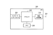
- FIG. 3 is a block diagram of the eNB 200.
- the eNB 200 includes an antenna 201, a radio transceiver 210, a network interface 220, a memory 230, and a processor 240.
- the memory 230 and the processor 240 constitute a control unit.
- the memory 230 may be integrated with the processor 240, and this set may be used as the processor.
- the antenna 201 and the wireless transceiver 210 are used for transmitting and receiving wireless signals.
- the antenna 201 includes a plurality of antenna elements.
- the wireless transceiver 210 converts the baseband signal output from the processor 240 into a wireless signal and transmits it from the antenna 201.
- the radio transceiver 210 converts a radio signal received by the antenna 201 into a baseband signal and outputs the baseband signal to the processor 240.
- the network interface 220 is connected to the neighboring eNB 200 via the X2 interface and is connected to the MME / S-GW 300 via the S1 interface.
- the network interface 220 is used for communication performed on the X2 interface and communication performed on the S1 interface.
- the memory 230 stores a program executed by the processor 240 and information used for processing by the processor 240.
- the processor 240 includes a baseband processor that performs modulation / demodulation and encoding / decoding of a baseband signal, and a CPU that executes programs stored in the memory 230 and performs various processes.
- the processor 240 executes various processes and various communication protocols described later.
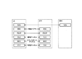
- FIG. 4 is a protocol stack diagram of a radio interface in the LTE system.
- the radio interface protocol is divided into layers 1 to 3 of the OSI reference model, and layer 1 is a physical (PHY) layer.
- Layer 2 includes a MAC (Media Access Control) layer, an RLC (Radio Link Control) layer, and a PDCP (Packet Data Convergence Protocol) layer.
- Layer 3 includes an RRC (Radio Resource Control) layer.
- the physical layer performs encoding / decoding, modulation / demodulation, antenna mapping / demapping, and resource mapping / demapping. Data is transmitted between the physical layer of the UE 100 and the physical layer of the eNB 200 via a physical channel.
- the MAC layer performs data priority control, retransmission processing by hybrid ARQ (HARQ), and the like. Data is transmitted via the transport channel between the MAC layer of the UE 100 and the MAC layer of the eNB 200.
- the MAC layer of the eNB 200 includes a scheduler that determines uplink / downlink transport formats (transport block size, modulation / coding scheme, and the like) and allocated resource blocks.
- the RLC layer transmits data to the RLC layer on the receiving side using the functions of the MAC layer and the physical layer. Data is transmitted between the RLC layer of the UE 100 and the RLC layer of the eNB 200 via a logical channel.
- the PDCP layer performs header compression / decompression and encryption / decryption.
- the RRC layer is defined only in the control plane. Control messages (RRC messages) for various settings are transmitted between the RRC layer of the UE 100 and the RRC layer of the eNB 200.
- the RRC layer controls the logical channel, the transport channel, and the physical channel according to establishment, re-establishment, and release of the radio bearer.
- RRC connected state When there is an RRC connection between the RRC of the UE 100 and the RRC of the eNB 200, the UE 100 is in a connected state (RRC connected state). Otherwise, the UE 100 is in an idle state (RRC idle state).
- the NAS (Non-Access Stratum) layer located above the RRC layer performs session management and mobility management.
- FIG. 5 is a configuration diagram of a radio frame used in the LTE system.
- OFDMA Orthogonal Frequency Division Multiplexing Access
- SC-FDMA Single Carrier Frequency Multiple Access
- the radio frame is composed of 10 subframes arranged in the time direction, and each subframe is composed of two slots arranged in the time direction.
- the length of each subframe is 1 ms, and the length of each slot is 0.5 ms.
- Each subframe includes a plurality of resource blocks (RB) in the frequency direction and includes a plurality of symbols in the time direction.
- the resource block includes a plurality of subcarriers in the frequency direction.
- frequency resources can be specified by resource blocks, and time resources can be specified by subframes (or slots).
- the section of the first few symbols of each subframe is a control region mainly used as a physical downlink control channel (PDCCH).
- the remaining section of each subframe is an area that can be used mainly as a physical downlink shared channel (PDSCH).
- PDSCH physical downlink shared channel
- reference signals such as cell-specific reference signals are distributed and arranged in each subframe.
- both ends in the frequency direction in each subframe are control regions mainly used as a physical uplink control channel (PUCCH). Further, the central portion in the frequency direction in each subframe is an area that can be used mainly as a physical uplink shared channel (PUSCH).
- PUCCH physical uplink control channel
- PUSCH physical uplink shared channel
- D2D communication The LTE system according to the present embodiment supports D2D communication.
- D2D communication will be described in comparison with normal communication (cellular communication) of the LTE system.
- a data path set between UEs passes through the EPC 20.
- a data path set between UEs does not pass through the EPC 20.
- FIG. 6 shows a data path in cellular communication.
- a data path means a transfer path of user data (user plane).
- the data path for cellular communication passes through the EPC 20 (S-GW 300). Specifically, a data path passing through the eNB 200-1, the S-GW 300, and the eNB 200-2 is set.
- FIG. 7 shows an example of a data path in D2D communication.
- D2D communication is performed between the UE 100-1 that has established a connection with the eNB 200-1 and the UE 100-2 that has established a connection with the eNB 200-2 is illustrated.
- the data path of the D2D communication does not go through the EPC 20 (S-GW 300).
- FIG. 7 illustrates a case of D2D communication in the direct communication mode.
- the other is a local relay mode in which the data path passes through the eNB 200.
- the local relay mode is referred to as a locally routed mode.
- the traffic load of the EPC 20 and the battery consumption of the UE 100 are reduced by performing D2D communication between the UE 100-1 and the UE 100-2. The effect of doing etc. is acquired.
- D2D communication As a case where D2D communication is started, (a) a case where D2D communication is started after the partner terminal is discovered by performing an operation for discovering the partner terminal, and (b) a partner terminal is discovered. There is a case where D2D communication is started without performing the operation for.
- D2D communication is started when one of the UEs 100-1 and 100-2 discovers the other UE 100 in the vicinity.
- the UE 100 discovers another UE 100 existing in the vicinity of the UE 100 in order to discover the partner terminal (Discover), and / or the UE 100 is discovered from the other UE 100 (Discoverable). It has a function.
- the UE 100 does not necessarily need to perform D2D communication even if it discovers the counterpart terminal.
- the UE 100-1 and the UE 100-2 may negotiate each other and then perform D2D communication after discovering each other. It may be determined.
- Each of the UE 100-1 and the UE 100-2 starts D2D communication when agreeing to perform D2D communication.
- the UE 100 starts broadcasting a signal for D2D communication by broadcasting.
- UE100 can start D2D communication irrespective of the presence or absence of a partner terminal's discovery.
- the D2D communication is performed in the frequency band of the LTE system (that is, in the frequency band of the cellular communication).
- the D2D communication is performed under the management of the eNB 200. Done.
- the eNB 200 configures a plurality of cells.
- two substantially overlapping cells (cell A and cell B) are illustrated, but the eNB 200 may constitute three or more cells.
- the plurality of cells have different frequencies (carrier frequencies). That is, the frequency to which cell A belongs and the frequency to which cell B belongs are different.
- Each of cell A and cell B is a cell (D2D support cell) that supports D2D communication. Therefore, each of the cell A and the cell B can perform management and control of D2D communication such as allocating radio resources for D2D communication.
- the eNB 200 knows that the cell A and the cell B support D2D communication.
- UE 100-1 and UE 100-2 are connected. That is, each of UE 100-1 and UE 100-2 is in a state (connection state) in which connection with cell A is established.
- UE 100-1 and UE 100-2 perform D2D communication in cell A.
- the UE 100-1 and / or the UE 100-2 may perform cellular communication in addition to D2D communication.
- ENB 200 (cell A) dynamically or semi-statically allocates radio resources for D2D communication (D2D resources) to UE 100-1 and UE 100-2. Further, the eNB 200 (cell A) may control transmission power in D2D communication.
- the eNB 200 may cause the UE 100-1 and the UE 100 in the cell A to -2 is assumed to be difficult to continue the D2D communication of -2.
- the radio environments of the UE 100-1 and the UE 100-2 can be grasped by a measurement report (Measurement Report) from the UE 100-1 and the UE 100-2, a measurement in the eNB 200, or the like. Further, the load in the cell A can be grasped from the radio resource consumption in the cell A or the traffic amount transmitted and received by the eNB 200 in the cell A.
- a measurement report Measurement Report
- the load in the cell A can be grasped from the radio resource consumption in the cell A or the traffic amount transmitted and received by the eNB 200 in the cell A.
- the eNB 200 determines that it is difficult to continue the D2D communication between the UE 100-1 and the UE 100-2 in the cell A, the eNB 200 transmits the UE 100-1 to the cell B (another D2D support cell) that supports the D2D communication. And the UE 100-2 performs inter-frequency handover. Then, the eNB 200 performs control so that the handover is performed while maintaining the D2D communication in the UE 100-1 and the UE 100-2.
- the eNB 200 determines to perform handover of the UE 100-1 and the UE 100-2 to the cell B, the eNB 200 secures radio resources for D2D communication in the cell B and then performs handover to the cell B. To UE100-1 and UE100-2. At that time, the eNB 200 may notify the UE 100-1 and the UE 100-2 that D2D communication is possible at the handover destination (or a radio resource allocated to D2D communication at the handover destination).
- the UE 100-1 and the UE 100-2 perform handover to the cell B while maintaining D2D communication under the control of the eNB 200. After the handover is completed, the UE 100-1 and the UE 100-2 perform D2D communication in a state where the connection with the cell B is established (connection state). Note that the UE 100-1 and / or the UE 100-2 may perform cellular communication in addition to D2D communication.
- the eNB 200 determines to perform handover from the cell A (D2D support cell) to the cell B (another D2D support cell)
- the eNB 200 performs the D2D communication with the UE 100-1 and the UE 100.
- -2 is controlled so that the handover is performed.
- the UE 100-1 and the UE 100-2 can perform handover while maintaining D2D communication according to a change in the communication status.
- intra-base station (Intra-eNB) handover has been described, but in the second embodiment, inter-base station (Inter-eNB) handover is described.
- Inter-eNB inter-base station
- the eNB 200-1 (base station) configures two cells (cell A and cell B) that are substantially overlapped.
- Cell A and cell B belong to different frequencies.
- Each of cell A and cell B supports D2D communication.
- the eNB 200-2 (adjacent base station) configures two cells (cell A 'and cell B') adjacent to the cell (cell A and cell B) of the eNB 200-1.
- Cell A 'and cell B' belong to different frequencies.
- each of the cell A 'and the cell B' supports D2D communication. Furthermore, each of cell A 'and cell B' supports handover that maintains D2D communication.
- the cell A ′ may be a cell that does not support D2D communication or a cell that does not support handover that maintains D2D communication.
- each of the eNB 200-1 and the eNB 200-2 is not limited to two cells, and may constitute three or more cells, or may constitute one cell.
- UE 100-1 and UE 100-2 are connected to cell A of eNB 200-1. That is, each of UE 100-1 and UE 100-2 is in a state (connection state) in which connection with cell A is established.
- UE 100-1 and UE 100-2 perform D2D communication in cell A.
- the UE 100-1 and / or the UE 100-2 may perform cellular communication in addition to D2D communication.
- ENB 200-1 (cell A) allocates radio resources for D2D communication (D2D resources) to UE 100-1 and UE 100-2 dynamically or semi-statically. Further, the eNB 200-1 (cell A) may control transmission power in D2D communication.
- the eNB 200 determines to perform the handover of the UE 100-1 and the UE 100-2 to the cell A ′ or the cell B ′.
- the radio environment of the UE 100-1 and the UE 100-2 can be grasped by a measurement report (Measurement Report) from the UE 100-1 and the UE 100-2.
- a measurement report Measurement Report
- the eNB 200-1 determines that the handover from the cell A to the cell B 'is performed, the eNB 200-1 controls the UE 100-1 and the UE 100-2 to perform the handover while maintaining the D2D communication.
- the handover procedure operation patterns 1 to 3 will be described later.
- the UE 100-1 and the UE 100-2 perform D2D communication in a state where the connection with the cell B 'is established (connection state) after completing the handover to the cell B' while maintaining the D2D communication. Note that the UE 100-1 and / or the UE 100-2 may perform cellular communication in addition to D2D communication.
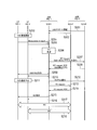
- FIG. 12 is a sequence diagram of the operation pattern 1 according to the present embodiment.
- the eNB 200-2 transmits D2D support information related to the support status of D2D communication in the cell A ′ and the cell B ′ to the eNB 200-1 on the X2 interface or the S1 interface.
- the D2D support information may be included in the eNB Configuration Update message indicating the setting status in the eNB 200-2.
- the D2D support information includes information indicating whether each of the cell A ′ and the cell B ′ supports D2D communication.
- the D2D support information may further include information indicating whether or not each of the cell A ′ and the cell B ′ supports handover for maintaining D2D communication.
- the eNB 200-2 transmits D2D support information to the eNB 200-1 when the support status of the D2D communication in the cell A 'and the cell B' is changed. Alternatively, the eNB 200-2 may periodically transmit D2D support information to the eNB 200-1.
- the eNB 200-1 When receiving the D2D support information from the eNB 200-2, the eNB 200-1 stores the received D2D support information.
- step S103 the UE 100-1 and the UE 100-2 start D2D communication in the cell A.
- each of the UE 100-1 and the UE 100-2 transmits a measurement report to the eNB 200-1.
- the measurement report includes information indicating the reference signal received power for each of the serving cell (cell A) and the neighboring cells (cell A ′, cell B ′, etc.).
- step S106 the eNB 200-1 performs a handover determination based on the measurement reports received from each of the UE 100-1 and the UE 100-2.
- the eNB 200-1 since the reference signal reception power for the cell B ′ is a good value and the cell B ′ supports D2D communication, the eNB 200-1 transmits the UE 100 from the cell A to the cell B ′. -1 and UE 100-2 are determined to be handed over.
- the eNB 200-1 transmits a handover request for requesting handover to the cell B ′ to the eNB 200-2 on the X2 interface or the S1 interface.
- the handover request includes information (D2D context) indicating that the UE 100-1 and the UE 100-2 are performing D2D communication.
- the eNB 200-1 may transmit a handover request for each of the UE 100-1 and the UE 100-2, or may collectively transmit a single handover request for the UE 100-1 and the UE 100-2.
- the eNB 200-2 Based on the handover request from the eNB 200-1, the eNB 200-2 considers the UE 100-1 and the UE 100-2 performing D2D communication, and determines whether to permit the handover request. Also, the eNB 200-2 makes preparations such as securing radio resources for D2D communication.
- the description will be made assuming that the eNB 200-2 permits the handover request and succeeds in securing radio resources for D2D communication.
- the eNB 200-2 transmits a permission response (HO Request ACK) including D2D allocation information related to allocation of radio resources for D2D communication in the cell B 'to the eNB 200-1 on the X2 interface or the S1 interface.
- the D2D allocation information is information indicating that the D2D communication can be allocated in the cell B ′.
- the D2D allocation information may be information indicating radio resources allocated for D2D communication.
- ENB 200-1 determines that handover to cell B 'is possible while maintaining D2D communication based on the permission response from eNB 200-2.
- the eNB 200-1 instructs the UE 100-1 and the UE 100-2 to perform an inter-frequency handover to the cell B ′.
- the eNB 200-1 may notify the UE 100-1 and the UE 100-2 that the D2D communication is possible at the handover destination (or the radio resource allocated to the D2D communication at the handover destination).
- steps S111 and S112 the UE 100-1 and the UE 100-2 perform handover to the cell B 'while maintaining D2D communication in accordance with an instruction (and notification) from the eNB 200-1.
- step S113 the UE 100-1 and the UE 100-2 perform D2D communication in a state where the connection with the cell B ′ is established (connection state).
- FIG. 13 is a sequence diagram of an operation pattern 2 according to the present embodiment.
- steps S201 to S207 are the same as in operation pattern 1.
- step S208 the eNB 200-2 considers the UE 100-1 and the UE 100-2 performing D2D communication based on the handover request from the eNB 200-1, and determines whether to permit the handover request. Judging. Also, the eNB 200-2 makes preparations such as securing radio resources for D2D communication.
- the description will proceed on the assumption that the radio resource for D2D communication has failed to be secured.
- the eNB 200-2 transmits a permission response (HO Request ACK) including D2D allocation information related to allocation of radio resources for D2D communication in the cell B 'to the eNB 200-1 on the X2 interface or the S1 interface.
- the D2D allocation information is information indicating that allocation of D2D communication is not possible in the cell B ′.
- the D2D assignment information may include information indicating a reason why D2D communication assignment is not possible in the cell B ′.
- the eNB 200-1 determines that the handover to the cell B ′ is impossible while maintaining the D2D communication based on the permission response from the eNB 200-2.
- the eNB 200-1 instructs the UE 100-1 and the UE 100-2 to stop the D2D communication.
- the eNB 200-1 may cancel radio resource allocation for D2D communication instead of instructing to stop D2D communication.
- step S211 the UE 100-1 and the UE 100-2 stop the D2D communication.
- step S212 the eNB 200-1 transmits information indicating that the handover to the cell B 'is stopped to the eNB 200-2 on the X2 interface or the S1 interface.
- step S213 the eNB 200-1 transmits a handover request for requesting handover to the cell A 'to the eNB 200-2 on the X2 interface or the S1 interface. This is because the cell A ′ may be able to resume D2D communication after the handover. In the measurement report described above, it is a condition that the reference signal received power for the cell A ′ is a good value (over the handover threshold).
- the eNB 200-2 determines whether to permit the handover request based on the handover request from the eNB 200-1. Here, the description will be made assuming that the eNB 200-2 permits the handover request.
- step S214 the eNB 200-2 transmits a permission response (HO Request ACK) to the eNB 200-1 on the X2 interface or the S1 interface.
- HO Request ACK a permission response
- the eNB 200-1 instructs the UE 100-1 and the UE 100-2 to perform an intra-frequency handover to the cell A ′ based on the permission response from the eNB 200-2. At that time, the eNB 200-1 may notify the UE 100-1 and the UE 100-2 that the handover destination supports D2D communication.
- FIG. 14 is a sequence diagram of an operation pattern 3 according to the present embodiment.
- steps S301 to S311 are the same as in operation pattern 2.
- Steps S312 and S313, the eNB 200-1 instructs the UE 100-1 and the UE 100-2 to perform an intra-frequency handover to the cell A ′.
- the eNB 200-1 may notify the UE 100-1 and the UE 100-2 that the handover destination supports D2D communication.
- steps S314 and S315 the UE 100-1 and the UE 100-2 perform handover to the cell A 'in response to an instruction (and notification) from the eNB 200-1.
- the eNB 200-1 controls the handover of the UE 100-1 and the UE 100-2 from the cell A to the cell B ′ based on the D2D support information from the eNB 200.
- the inter-base station (Inter-eNB) handover of the UE 100-1 and the UE 100-2 during the D2D communication can be appropriately controlled.
- the cell A ′ and the cell B ′ support D2D communication and support handover for maintaining D2D communication.
- the eNB 200-1 determines that a handover is performed from the cell A to the cell B ', the eNB 200-1 controls the UE 100-1 and the UE 100-2 to perform the handover while maintaining the D2D communication.
- the UE 100-1 and the UE 100-2 can perform inter-base station (Inter-eNB) handover while maintaining D2D communication.
- Inter-eNB inter-base station
- the eNB 200-1 determines that the handover is performed from the cell A to the cell B ′, the handover including information indicating that the UE 100-1 and the UE 100-2 are performing D2D communication.
- the request is transmitted to the eNB 200-2.
- the eNB 200-2 can determine whether to permit the handover request in consideration of the UE 100-1 and the UE 100-2 performing D2D communication.
- the eNB 200-2 can make preparations such as securing radio resources for D2D communication.
- the eNB 200-2 when the eNB 200-2 permits a handover request, the eNB 200-2 transmits a permission response including D2D allocation information related to allocation of radio resources for D2D communication in the cell B ′ to the eNB 200-1.
- the eNB 200-1 can appropriately control the handover in consideration of whether or not radio resources for D2D communication are allocated in the eNB 200-2.
- the eNB 200-1 stops the handover to the cell B ′ when the permission response is received from the eNB 200-2 and the D2D allocation information indicates that radio resources for D2D communication cannot be allocated. .
- the D2D allocation information indicates that radio resources for D2D communication cannot be allocated.
- the eNB 200-1 receives the permission response from the eNB 200-2, and when the frequency to which the cell A belongs and the frequency to which the cell B ′ belongs are different, (Inter-frequency) Instructs UE 100-1 and UE 100-2 to perform handover. Accordingly, even when the frequency to which the cell A belongs and the frequency to which the cell B ′ belongs are different, the UE 100-1 and the UE 100-2 can perform handover while maintaining D2D communication.
- the cell A ′ and the cell B ′ support D2D communication and support handover for maintaining D2D communication.
- the cell A ′ and the cell B ′ support D2D communication but do not support handover for maintaining D2D communication.
- the cell A ′ may be a cell that does not support D2D communication.
- the eNB 200-1 and the eNB 200-2 share in advance that a handover for maintaining D2D communication is not supported when there is a UE 100 that performs D2D communication in its own cell.
- FIG. 15 is a sequence diagram according to the present embodiment. The description of the same operations as those in the second embodiment described above will be omitted as appropriate.
- step S401 the UE 100-1 and the UE 100-2 start D2D communication in the cell A.
- the eNB 200-2 transmits D2D support information regarding the support status of D2D communication in the cell A ′ and the cell B ′ to the eNB 200-1 on the X2 interface or the S1 interface.
- the D2D support information includes information indicating whether each of the cell A ′ and the cell B ′ supports handover for maintaining D2D communication.
- the eNB 200-2 may transmit D2D support information to the eNB 200-1 in response to a request from the eNB 200-1.
- the eNB 200-1 When receiving the D2D support information from the eNB 200-2, the eNB 200-1 stores the received D2D support information.
- each of the UE 100-1 and the UE 100-2 transmits a measurement report to the eNB 200-1.
- step S406 the eNB 200-1 performs handover determination based on the measurement reports received from the UE 100-1 and the UE 100-2.
- the eNB 200-1 since the reference signal reception power for the cell B ′ is a good value and the cell B ′ supports D2D communication, the eNB 200-1 transmits the UE 100 from the cell A to the cell B ′. -1 and UE 100-2 are determined to be handed over.
- Steps S407 and S408 since the eNB 200-1 knows that the cell B ′ does not support the handover for maintaining the D2D communication, the eNB 200-1 instructs the UE 100-1 and the UE 100-2 to stop the D2D communication. Alternatively, the eNB 200-1 may cancel radio resource allocation for D2D communication instead of instructing to stop D2D communication.
- step S409 the UE 100-1 and the UE 100-2 stop the D2D communication.
- step S410 the eNB 200-1 transmits a handover request for requesting a handover to the cell B ′ to the eNB 200-2 on the X2 interface or the S1 interface.
- the information (D2D context) described above is not included in the handover request, but the eNB 200-1 may include the information (D2D context) in the handover request.
- the eNB 200-2 determines whether to permit the handover request based on the handover request from the eNB 200-1. Here, the description will be made assuming that the eNB 200-2 permits the handover request.
- step S411 the eNB 200-2 transmits a permission response (HO Request ACK) to the eNB 200-1 on the X2 interface or the S1 interface.
- HO Request ACK a permission response
- Steps S412 and S413, the eNB 200-1 instructs the UE 100-1 and the UE 100-2 to perform an inter-frequency handover to the cell B ′.
- the eNB 200-1 may notify the UE 100-1 and the UE 100-2 that the handover destination supports D2D communication.
- Steps S414 and S415 the UE 100-1 and the UE 100-2 perform handover to the cell B 'in response to an instruction (and notification) from the eNB 200-1.
- the description will be made assuming that UE 100-1 and UE 100-2 desire to resume D2D communication after handover.
- each of the UE 100-1 and the UE 100-2 transmits information (Indication) indicating that D2D communication is to be performed to the eNB 200-2 (cell B ').
- Information indicating that D2D communication is to be performed to the eNB 200-2 (cell B ').
- the description will be made assuming that the eNB 200-2 permits the D2D communication.
- Steps S418 and S419 the eNB 200-2 notifies the UE 100-1 and the UE 100-2 of permission of D2D communication and / or radio resources for D2D communication.
- step S420 the UE 100-1 and the UE 100-2 resume the D2D communication in a state where the connection with the cell B ′ is established (connection state).
- the eNB 200-1 when the eNB 200-1 determines to perform handover from the cell A to the cell B ′, the eNB 200-1 stops the D2D communication from the UE 100-1 and the UE 100-2, and then Control to perform handover. Thereby, since D2D communication can be canceled before a handover, it is possible to avoid a situation in which the D2D communication is canceled immediately after a handover and an unexpected error occurs.
- the UE 100-1 and the UE 100-2 notify the cell B ′ that the D2D communication is desired when the handover to the cell B ′ is performed and when it is desired to resume the D2D communication. . Thereby, if it is desired to resume D2D communication after the handover, the UE 100-1 and the UE 100-2 can resume D2D communication.
- the cell A ′ and the cell B ′ support D2D communication.
- the cell A ′ and the cell B ′ do not support D2D communication.
- the operation is the same as in FIG. That is, when it is determined that a handover is performed from the cell A to the cell B ′, the eNB 200-1 controls the UE 100-1 and the UE 100-2 to stop the D2D communication and then perform the handover. Thereby, since D2D communication can be canceled before a handover, it is possible to avoid a situation in which the D2D communication is canceled immediately after a handover and an unexpected error occurs.
- the UE 100-1 and the UE 100-2 cannot resume D2D communication even when performing handover to the cell B ′ and wishing to resume D2D communication. Should.
- both the UE 100-1 and the UE 100-2 have established a connection with the eNB 200 has been described.
- a so-called anchor UE May establish a connection with the eNB 200.
- the anchor UE performs communication with the eNB 200 on behalf of the UE group that performs D2D communication.
- the eNB 200 does not need to give instructions or notifications to both the UE 100-1 and the UE 100-2, and may only give instructions or notifications to the anchor UE.
- the eNB 200-1 receives the D2D support information in the cell (specifically, the cell A ′ and the cell B ′) of the eNB 200-2 (neighboring base station) from the eNB 200-2.
- the eNB 200-1 may grasp whether or not the cell of the eNB 200-2 supports D2D communication based on a notification from an entity included in the core network.
- the entity sets the same radio resource and / or frequency band as a radio resource and / or frequency band used for D2D communication in a plurality of eNBs 200 existing in a predetermined range (for example, a predetermined tracking area). Is sent (corresponding to D2D support information). In the following, the description will be made assuming that the entity transmits a notification for setting the same radio resource as a radio resource used for D2D communication.
- each of the eNB 200-1 and the eNB 200-2 included in the plurality of eNBs 200 sets the radio resource designated by the entity to the radio resource used for the D2D communication based on the notification from the entity.
- each cell of eNB200-1 and eNB200-2 supports D2D communication. Therefore, the eNB 200-1 can determine from the notification from the entity that the cell of the eNB 200-2 supports D2D communication, and thus can determine whether the cell of the eNB 200-2 supports D2D communication.
- Each of the plurality of eNBs 200 can perform the handover while maintaining the D2D communication by allocating the radio resource designated by the entity to the UE 100 that is the target of the handover.
- each of the plurality of eNBs 200 may set a radio resource designated by the entity as a radio resource dedicated to D2D communication, or may be a radio resource shared by D2D communication and cellular communication. In addition, each of the plurality of eNBs 200 may uniquely set a radio resource other than the radio resource designated by the entity as a radio resource used for D2D communication.
- the entity may be any device that can transmit to the plurality of eNBs 200 notifications for setting the same radio resource and / or frequency band as radio resources and / or frequency bands used for D2D communication.
- the entity may be MMC or OAM, or may be a D2D management server installed to manage D2D communication.
- the present invention is not limited to the LTE system, and the present invention may be applied to a system other than the LTE system.
- the mobile communication system, the base station, the processor, and the communication control method according to the present invention are useful in the mobile communication field because they can appropriately perform handover control for user terminals in D2D communication.
Abstract
Description
実施形態に係る移動通信システムは、直接的な端末間通信であるD2D通信をサポートするD2Dサポートセルを構成する基地局と、前記D2Dサポートセルにおいて前記D2D通信を行うユーザ端末と、を有する。「直接的な端末間通信」とは、少なくともコアネットワークを介さない端末間通信をいう。前記基地局は、前記ユーザ端末のハンドオーバを制御する制御部を含む。前記制御部は、前記ユーザ端末のハンドオーバ対象のセルにおける前記D2D通信のサポート状況に基づいて、前記ハンドオーバを制御する。これにより、D2D通信をサポートするセルとD2D通信をサポートしないセルとが混在していても、ハンドオーバを適切に制御できる。
以下、第1実施形態について説明する。
図1は、本実施形態に係るLTEシステムの構成図である。
本実施形態に係るLTEシステムは、D2D通信をサポートする。ここでは、D2D通信を、LTEシステムの通常の通信(セルラ通信)と比較して説明する。
以下、本実施形態に係る動作について説明する。図8及び図9は、本実施形態に係る動作を説明するための図である。
上述したように、本実施形態では、eNB200は、セルA(D2Dサポートセル)からセルB(別のD2Dサポートセル)に対してハンドオーバを行うと判断した場合に、D2D通信をUE100-1及びUE100-2に維持させながら当該ハンドオーバを行うように制御する。これにより、通信状況の変化などに応じて、UE100-1及びUE100-2がD2D通信を維持しながらハンドオーバを行うことができる。
以下、第2実施形態について、上述した第1実施形態との相違点を主として説明する。
図10及び図11は、本実施形態に係る動作を説明するための図である。
次に、本実施形態に係る動作パターン1について説明する。図12は、本実施形態に係る動作パターン1のシーケンス図である。
次に、本実施形態に係る動作パターン2について、上述した動作パターン1との相違点を主として説明する。図13は、本実施形態に係る動作パターン2のシーケンス図である。
次に、本実施形態に係る動作パターン3について、上述した動作パターン2との相違点を主として説明する。図14は、本実施形態に係る動作パターン3のシーケンス図である。
上述したように、本実施形態では、eNB200-1は、eNB200からのD2Dサポート情報に基づいて、セルAからセルB’に対するUE100-1及びUE100-2のハンドオーバを制御する。これにより、D2D通信中のUE100-1及びUE100-2の基地局間(Inter-eNB)ハンドオーバを適切に制御できる。
以下、第3実施形態について、上述した第2実施形態との相違点を主として説明する。
以下、第4実施形態について、上述した第2実施形態及び第3実施形態との相違点を主として説明する。
上記のように、本発明は実施形態によって記載したが、この開示の一部をなす論述及び図面はこの発明を限定するものであると理解すべきではない。この開示から当業者には様々な代替実施形態、実施例及び運用技術が明らかとなる。
Claims (14)
- 直接的な端末間通信であるD2D通信をサポートするD2Dサポートセルを構成する基地局と、
前記D2Dサポートセルにおいて前記D2D通信を行うユーザ端末と、
を有する移動通信システムであって、
前記基地局は、前記ユーザ端末のハンドオーバを制御する制御部を含み、
前記制御部は、前記ユーザ端末のハンドオーバ対象のセルにおける前記D2D通信のサポート状況に基づいて、前記ハンドオーバを制御することを特徴とする移動通信システム。 - 前記基地局は、前記D2Dサポートセルに加えて、前記D2D通信をサポートする別のD2Dサポートセルを構成しており、
前記制御部は、前記D2Dサポートセルから前記別のD2Dサポートセルに対して前記ハンドオーバを行うと判断した場合に、前記D2D通信を前記ユーザ端末に維持させながら当該ハンドオーバを行うように制御することを特徴とする請求項1に記載の移動通信システム。 - 前記D2Dサポートセルと隣接する隣接セルを構成する隣接基地局をさらに有し、
前記隣接基地局は、前記隣接セルにおける前記D2D通信のサポート状況に関するD2Dサポート情報を前記基地局に送信し、
前記制御部は、前記D2Dサポート情報に基づいて、前記隣接セルに対する前記ハンドオーバを制御することを特徴とする請求項1に記載の移動通信システム。 - 前記隣接セルは、前記D2D通信をサポートし、かつ、前記D2D通信を維持する前記ハンドオーバをサポートしており、
前記制御部は、前記D2Dサポートセルから前記隣接セルに対して前記ハンドオーバを行うと判断した場合に、前記D2D通信を前記ユーザ端末に維持させながら当該ハンドオーバを行うように制御することを特徴とする請求項3に記載の移動通信システム。 - 前記制御部は、前記D2Dサポートセルから前記隣接セルに対して前記ハンドオーバを行うと判断した場合に、前記ユーザ端末が前記D2D通信を行っていることを示す情報を含んだハンドオーバ要求を前記隣接基地局に送信することを特徴とする請求項4に記載の移動通信システム。
- 前記隣接基地局は、前記ハンドオーバ要求を許可する場合に、前記隣接セルにおける前記D2D通信用の無線リソースの割当に関するD2D割当情報を含んだ許可応答を前記基地局に送信することを特徴とする請求項5に記載の移動通信システム。
- 前記制御部は、前記隣接基地局から前記許可応答を受信した場合で、かつ、前記D2D割当情報が前記D2D通信用の無線リソースの割当不可を示す場合に、前記隣接セルに対する前記ハンドオーバを中止することを特徴とする請求項6に記載の移動通信システム。
- 前記制御部は、前記隣接基地局からの前記許可応答を受信した場合で、かつ、前記D2Dサポートセルが属する周波数と前記隣接セルが属する周波数とが異なる場合に、前記隣接セルへの周波数間ハンドオーバを前記ユーザ端末に指示することを特徴とする請求項6に記載の移動通信システム。
- 前記隣接セルは、前記D2D通信をサポートし、かつ、前記D2D通信を維持する前記ハンドオーバをサポートしておらず、
前記制御部は、前記D2Dサポートセルから前記隣接セルに対して前記ハンドオーバを行うと判断した場合に、前記D2D通信を前記ユーザ端末に中止させた後、当該ハンドオーバを行うように制御することを特徴とする請求項3に記載の移動通信システム。 - 前記ユーザ端末は、前記隣接セルに対する前記ハンドオーバを行った場合で、かつ、前記D2D通信の再開を希望する場合に、前記D2D通信を行いたい旨を前記隣接セルに通知することを特徴とする請求項9に記載の移動通信システム。
- 前記隣接セルは、前記D2D通信をサポートしておらず、
前記制御部は、前記D2Dサポートセルから前記隣接セルに対して前記ハンドオーバを行うと判断した場合に、前記D2D通信を前記ユーザ端末に中止させた後、当該ハンドオーバを行うように制御することを特徴とする請求項3に記載の移動通信システム。 - 直接的な端末間通信であるD2D通信をサポートするD2Dサポートセルを構成する基地局であって、
前記D2Dサポートセルにおいて前記D2D通信を行うユーザ端末のハンドオーバを制御する制御部を含み、
前記制御部は、前記ユーザ端末のハンドオーバ対象のセルにおける前記D2D通信のサポート状況に基づいて、前記ハンドオーバを制御することを特徴とする基地局。 - 直接的な端末間通信であるD2D通信をサポートするD2Dサポートセルを構成する基地局に備えられるプロセッサであって、
前記D2Dサポートセルにおいて前記D2D通信を行うユーザ端末のハンドオーバを、前記ユーザ端末のハンドオーバ対象のセルにおける前記D2D通信のサポート状況に基づいて制御することを特徴とするプロセッサ。 - 直接的な端末間通信であるD2D通信をサポートするD2Dサポートセルを構成する基地局と、
前記D2Dサポートセルにおいて前記D2D通信を行うユーザ端末と、
を有する移動通信システムで用いられる通信制御方法であって、
前記基地局が、前記ユーザ端末のハンドオーバを制御するステップAを含み、
前記ステップAにおいて、前記基地局は、前記ユーザ端末のハンドオーバ対象のセルにおける前記D2D通信のサポート状況に基づいて、前記ハンドオーバを制御することを特徴とする通信制御方法。
Priority Applications (3)
| Application Number | Priority Date | Filing Date | Title |
|---|---|---|---|
| EP13858061.8A EP2928263A4 (en) | 2012-11-28 | 2013-11-11 | MOBILE COMMUNICATION SYSTEM, BASIC STATION, PROCESSOR AND COMMUNICATION CONTROL METHOD |
| JP2014550107A JP6045602B2 (ja) | 2012-11-28 | 2013-11-11 | 移動通信システム、基地局、プロセッサ、及び通信制御方法 |
| US14/647,809 US9629057B2 (en) | 2012-11-28 | 2013-11-11 | Mobile communication system, base station, processor, and communication control method |
Applications Claiming Priority (2)
| Application Number | Priority Date | Filing Date | Title |
|---|---|---|---|
| US201261730618P | 2012-11-28 | 2012-11-28 | |
| US61/730,618 | 2012-11-28 |
Publications (1)
| Publication Number | Publication Date |
|---|---|
| WO2014084028A1 true WO2014084028A1 (ja) | 2014-06-05 |
Family
ID=50827674
Family Applications (1)
| Application Number | Title | Priority Date | Filing Date |
|---|---|---|---|
| PCT/JP2013/080396 WO2014084028A1 (ja) | 2012-11-28 | 2013-11-11 | 移動通信システム、基地局、プロセッサ、及び通信制御方法 |
Country Status (4)
| Country | Link |
|---|---|
| US (1) | US9629057B2 (ja) |
| EP (1) | EP2928263A4 (ja) |
| JP (2) | JP6045602B2 (ja) |
| WO (1) | WO2014084028A1 (ja) |
Cited By (5)
| Publication number | Priority date | Publication date | Assignee | Title |
|---|---|---|---|---|
| WO2016056153A1 (ja) * | 2014-10-07 | 2016-04-14 | 日本電気株式会社 | 無線端末、制御装置、及びこれらの方法 |
| JP2016513892A (ja) * | 2013-03-08 | 2016-05-16 | ノキア テクノロジーズ オーユー | デバイス間通信のハンドオーバのための方法及び装置 |
| WO2016209467A1 (en) * | 2015-06-26 | 2016-12-29 | Qualcomm Incorporated | Dynamic cell reselection to improve device-to-device communications |
| JPWO2016047507A1 (ja) * | 2014-09-25 | 2017-07-13 | 京セラ株式会社 | ユーザ端末、サービス制御装置、及び基地局 |
| JP2019501583A (ja) * | 2015-12-02 | 2019-01-17 | エルジー エレクトロニクス インコーポレイティド | 無線通信システムにおけるマスタ端末及びそのコンパニオン装置のモビリティをサポートする方法及び装置 |
Families Citing this family (13)
| Publication number | Priority date | Publication date | Assignee | Title |
|---|---|---|---|---|
| KR102020350B1 (ko) * | 2013-07-19 | 2019-09-10 | 삼성전자 주식회사 | 무선이동통신시스템에서 d2d 통신을 지원/사용하는 단말기의 이동성을 지원하는 방안 |
| US9900810B2 (en) * | 2013-10-03 | 2018-02-20 | Lg Electronics Inc. | Method and apparatus for handling radio resources for device-to-device operation in wireless communication system |
| US20170048647A1 (en) * | 2014-05-06 | 2017-02-16 | Lg Electronics Inc. | Method for device-to-device (d2d) operation executed by terminal in wireless communication system and terminal using the method |
| CN105101046B (zh) * | 2014-05-14 | 2020-11-03 | 索尼公司 | 无线通信系统中的电子设备和无线通信方法 |
| WO2016015238A1 (zh) * | 2014-07-30 | 2016-02-04 | 富士通株式会社 | 切换过程中的d2d资源分配方法、装置以及通信系统 |
| US9883426B2 (en) * | 2014-07-31 | 2018-01-30 | Microsoft Technology Licensing, Llc. | Enhanced reporting for handover in device-to-device communication |
| US9992815B2 (en) * | 2015-04-09 | 2018-06-05 | Industrial Technology Research Institute | Method of performing handover procedure, making handover decision for device-to-device communications and control node thereof |
| KR102005999B1 (ko) * | 2015-04-11 | 2019-07-31 | 후아웨이 테크놀러지 컴퍼니 리미티드 | 자원 할당 방법, 장치 및 시스템 |
| WO2017123004A1 (ko) * | 2016-01-13 | 2017-07-20 | 엘지전자(주) | V2x 서비스를 위한 단말의 인터페이스 변경 방법 및 이를 위한 장치 |
| CN113411859A (zh) * | 2016-06-22 | 2021-09-17 | 华为技术有限公司 | 一种通信路径变更方法及设备 |
| US10244522B2 (en) | 2017-03-03 | 2019-03-26 | Qualcomm Incorporated | Signaling for multiplexing of low latency communication and sidelink communications |
| CN108684218B (zh) * | 2017-03-13 | 2021-02-12 | 华为技术有限公司 | 切换方法和装置 |
| US11800584B2 (en) * | 2019-07-12 | 2023-10-24 | Parallel Wireless, Inc. | 5G mobile network with intelligent 5G non-standalone (NSA) radio access network (RAN) |
Citations (3)
| Publication number | Priority date | Publication date | Assignee | Title |
|---|---|---|---|---|
| WO2005053346A1 (en) * | 2003-11-27 | 2005-06-09 | Koninklijke Philips Electronics N.V. | Method, user equipment and network for performing a handover for user equipments in peer-to-peer communication mode, to a cell whose link performance is a predefined value higher than that of the active cell |
| WO2011116017A1 (en) * | 2010-03-17 | 2011-09-22 | Qualcomm Incorporated | Method and apparatus for establishing and maintaining peer-to-peer (p2p) communication on unlicensed spectrum |
| CN102202361A (zh) * | 2010-03-23 | 2011-09-28 | 华为技术有限公司 | 一种用户在基站间的切换接入控制方法、装置和系统 |
Family Cites Families (9)
| Publication number | Priority date | Publication date | Assignee | Title |
|---|---|---|---|---|
| CN102334370B (zh) * | 2009-01-16 | 2014-10-29 | 诺基亚公司 | 调度用于设备到设备通信的资源的装置和方法 |
| US9622131B2 (en) * | 2010-03-05 | 2017-04-11 | Nokia Technologies Oy | Handover of direct peer to peer communication |
| US8913511B2 (en) * | 2010-04-01 | 2014-12-16 | Qualcomm Incorporated | Interference management to support peer-to-peer communication in a wide area network |
| WO2011147462A1 (en) * | 2010-05-28 | 2011-12-01 | Nokia Siemens Networks Oy | Method and apparatus for device-to-device communications |
| JP2012009945A (ja) | 2010-06-22 | 2012-01-12 | Sharp Corp | 無線通信システム、基地局装置および通信方法 |
| JP5763835B2 (ja) * | 2011-04-19 | 2015-08-12 | テレフオンアクチーボラゲット エル エム エリクソン(パブル) | 干渉を処理し及び無線リソースを適宜スケジューリングするための無線基地局及び無線基地局における方法 |
| EP2710839A1 (en) * | 2011-05-17 | 2014-03-26 | Telefonaktiebolaget LM Ericsson (PUBL) | Method and arrangement in a telecommunication system |
| CN104170446B (zh) * | 2012-03-16 | 2018-11-30 | 瑞典爱立信有限公司 | 用于利用保护子帧的小区间干扰协调的方法和设备 |
| EP2918101A4 (en) * | 2012-11-09 | 2016-07-27 | Nokia Technologies Oy | METHOD, APPARATUS AND COMPUTER PROGRAM PRODUCT FOR PATH SWITCHING IN DEVICE DEVICE COMMUNICATIONS |
-
2013
- 2013-11-11 US US14/647,809 patent/US9629057B2/en active Active
- 2013-11-11 JP JP2014550107A patent/JP6045602B2/ja active Active
- 2013-11-11 EP EP13858061.8A patent/EP2928263A4/en not_active Withdrawn
- 2013-11-11 WO PCT/JP2013/080396 patent/WO2014084028A1/ja active Application Filing
-
2016
- 2016-11-15 JP JP2016222190A patent/JP6272444B2/ja active Active
Patent Citations (14)
| Publication number | Priority date | Publication date | Assignee | Title |
|---|---|---|---|---|
| CN1887021A (zh) * | 2003-11-27 | 2006-12-27 | 皇家飞利浦电子股份有限公司 | 将处于 p 2 p通信模式的用户终端切换到其链路性能比激活小区的链路性能高出一预定值的小区的方法、用户终端和网络 |
| JP2007512752A (ja) * | 2003-11-27 | 2007-05-17 | コーニンクレッカ フィリップス エレクトロニクス エヌ ヴィ | 活動セルのものより所定値高いリンク性能を持つセルへの、ピアツーピア通信モードのユーザ装置のためのハンドオーバを実行する方法、ユーザ装置及びネットワーク |
| US20070115884A1 (en) * | 2003-11-27 | 2007-05-24 | Koninklijke Philips Electronics N.V. | Method, user equipment and network for performing a handover for user equipments in peer-to-peer communication mode, to a cell whose link performance is a predefined value higher than that of the active cell |
| WO2005053346A1 (en) * | 2003-11-27 | 2005-06-09 | Koninklijke Philips Electronics N.V. | Method, user equipment and network for performing a handover for user equipments in peer-to-peer communication mode, to a cell whose link performance is a predefined value higher than that of the active cell |
| CN102812772A (zh) * | 2010-03-17 | 2012-12-05 | 高通股份有限公司 | 用于在未授权频谱上建立和维护对等(p2p)通信的方法和装置 |
| WO2011116017A1 (en) * | 2010-03-17 | 2011-09-22 | Qualcomm Incorporated | Method and apparatus for establishing and maintaining peer-to-peer (p2p) communication on unlicensed spectrum |
| US20110228666A1 (en) * | 2010-03-17 | 2011-09-22 | Qualcomm Incorporated | Method and apparatus for establishing and maintaining peer-to-peer (p2p) communication on unlicensed spectrum |
| JP2013523018A (ja) * | 2010-03-17 | 2013-06-13 | クゥアルコム・インコーポレイテッド | 免許不要スペクトルでピアツーピア(p2p)通信を確立し維持するための方法及び装置 |
| CN102202361A (zh) * | 2010-03-23 | 2011-09-28 | 华为技术有限公司 | 一种用户在基站间的切换接入控制方法、装置和系统 |
| KR20120138792A (ko) * | 2010-03-23 | 2012-12-26 | 후아웨이 테크놀러지 컴퍼니 리미티드 | 기지국들 간의 사용자의 액세스 제어 핸드오버를 위한 방법, 기지국 및 시스템 |
| EP2552155A1 (en) * | 2010-03-23 | 2013-01-30 | Huawei Technologies Co., Ltd. | Access control method for user handover between base stations, base station and system |
| WO2011116694A1 (zh) * | 2010-03-23 | 2011-09-29 | 华为技术有限公司 | 一种用户在基站间的切换接入控制方法、基站和系统 |
| JP2013530550A (ja) * | 2010-03-23 | 2013-07-25 | 華為技術有限公司 | 基地局間でのユーザ・ハンドオーバのためのアクセス制御方法、基地局、及びシステム |
| US20130260768A1 (en) * | 2010-03-23 | 2013-10-03 | Huawei Technologies Co., Ltd. | Method, Apparatus, and System for Access Control Handover of User between Base Stations |
Non-Patent Citations (2)
| Title |
|---|
| "TR 22.803 V0.3.0", 3GPP TECHNICAL REPORT, May 2012 (2012-05-01) |
| See also references of EP2928263A4 |
Cited By (14)
| Publication number | Priority date | Publication date | Assignee | Title |
|---|---|---|---|---|
| US9730134B2 (en) | 2013-03-08 | 2017-08-08 | Nokia Technologies Oy | Method and apparatus for handover of device-to-device communications |
| JP2016513892A (ja) * | 2013-03-08 | 2016-05-16 | ノキア テクノロジーズ オーユー | デバイス間通信のハンドオーバのための方法及び装置 |
| EP3200556A4 (en) * | 2014-09-25 | 2018-05-23 | Kyocera Corporation | User terminal, service control device, and base station |
| JPWO2016047507A1 (ja) * | 2014-09-25 | 2017-07-13 | 京セラ株式会社 | ユーザ端末、サービス制御装置、及び基地局 |
| US10531458B2 (en) | 2014-09-25 | 2020-01-07 | Kyocera Corporation | User terminal, service control apparatus, and base station |
| KR20170048455A (ko) | 2014-10-07 | 2017-05-08 | 닛본 덴끼 가부시끼가이샤 | 무선 단말, 제어 장치, 및 이들의 방법 |
| CN106797592A (zh) * | 2014-10-07 | 2017-05-31 | 日本电气株式会社 | 无线电终端、控制设备及其方法 |
| WO2016056153A1 (ja) * | 2014-10-07 | 2016-04-14 | 日本電気株式会社 | 無線端末、制御装置、及びこれらの方法 |
| CN106797592B (zh) * | 2014-10-07 | 2020-09-08 | 日本电气株式会社 | 无线电终端、控制设备及其方法 |
| US9655039B2 (en) | 2015-06-26 | 2017-05-16 | Qualcomm Incorporated | Dynamic cell reselection to improve device-to-device communications |
| WO2016209467A1 (en) * | 2015-06-26 | 2016-12-29 | Qualcomm Incorporated | Dynamic cell reselection to improve device-to-device communications |
| CN107787600A (zh) * | 2015-06-26 | 2018-03-09 | 高通股份有限公司 | 用于改善设备对设备通信的动态蜂窝小区重选 |
| TWI630833B (zh) * | 2015-06-26 | 2018-07-21 | 高通公司 | 用於改善設備對設備通訊的動態細胞服務區重選 |
| JP2019501583A (ja) * | 2015-12-02 | 2019-01-17 | エルジー エレクトロニクス インコーポレイティド | 無線通信システムにおけるマスタ端末及びそのコンパニオン装置のモビリティをサポートする方法及び装置 |
Also Published As
| Publication number | Publication date |
|---|---|
| EP2928263A4 (en) | 2016-07-27 |
| EP2928263A1 (en) | 2015-10-07 |
| JPWO2014084028A1 (ja) | 2017-01-05 |
| JP2017073797A (ja) | 2017-04-13 |
| US9629057B2 (en) | 2017-04-18 |
| US20150312836A1 (en) | 2015-10-29 |
| JP6045602B2 (ja) | 2016-12-14 |
| JP6272444B2 (ja) | 2018-01-31 |
Similar Documents
| Publication | Publication Date | Title |
|---|---|---|
| JP6272444B2 (ja) | 通信方法、基地局、及びプロセッサ | |
| JP6502582B2 (ja) | 基地局及びユーザ端末 | |
| JP5981671B2 (ja) | 基地局、ユーザ端末及びプロセッサ | |
| JP6280669B1 (ja) | 基地局、方法、及びシステム | |
| WO2015064679A1 (ja) | 移動通信システム及びユーザ端末 | |
| WO2014163143A1 (ja) | 移動通信システム及びユーザ端末 | |
| WO2015053382A1 (ja) | 通信制御方法、ユーザ端末及び通信装置 | |
| JP6140180B2 (ja) | 移動通信システム、ユーザ端末、基地局、プロセッサ及び通信制御方法 | |
| WO2014129465A1 (ja) | 通信制御方法、ユーザ端末及び基地局 | |
| JP2016106449A (ja) | ユーザ端末、基地局、及びプロセッサ | |
| EP3110194A1 (en) | Moving body communication system, specific base station, and user terminal | |
| JP6302129B1 (ja) | 基地局及びプロセッサ | |
| JP6378256B2 (ja) | ユーザ端末、通信制御装置、及びプロセッサ |
Legal Events
| Date | Code | Title | Description |
|---|---|---|---|
| 121 | Ep: the epo has been informed by wipo that ep was designated in this application |
Ref document number: 13858061 Country of ref document: EP Kind code of ref document: A1 |
|
| ENP | Entry into the national phase |
Ref document number: 2014550107 Country of ref document: JP Kind code of ref document: A |
|
| WWE | Wipo information: entry into national phase |
Ref document number: 14647809 Country of ref document: US |
|
| NENP | Non-entry into the national phase |
Ref country code: DE |
|
| REEP | Request for entry into the european phase |
Ref document number: 2013858061 Country of ref document: EP |
|
| WWE | Wipo information: entry into national phase |
Ref document number: 2013858061 Country of ref document: EP |