WO2014079705A1 - A refrigerator comprising an ice making unit - Google Patents
A refrigerator comprising an ice making unit Download PDFInfo
- Publication number
- WO2014079705A1 WO2014079705A1 PCT/EP2013/073380 EP2013073380W WO2014079705A1 WO 2014079705 A1 WO2014079705 A1 WO 2014079705A1 EP 2013073380 W EP2013073380 W EP 2013073380W WO 2014079705 A1 WO2014079705 A1 WO 2014079705A1
- Authority
- WO
- WIPO (PCT)
- Prior art keywords
- ice cube
- cube tray
- channel
- ice
- stopper
- Prior art date
- Legal status (The legal status is an assumption and is not a legal conclusion. Google has not performed a legal analysis and makes no representation as to the accuracy of the status listed.)
- Ceased
Links
Images


Classifications
-
- F—MECHANICAL ENGINEERING; LIGHTING; HEATING; WEAPONS; BLASTING
- F25—REFRIGERATION OR COOLING; COMBINED HEATING AND REFRIGERATION SYSTEMS; HEAT PUMP SYSTEMS; MANUFACTURE OR STORAGE OF ICE; LIQUEFACTION SOLIDIFICATION OF GASES
- F25C—PRODUCING, WORKING OR HANDLING ICE
- F25C1/00—Producing ice
- F25C1/22—Construction of moulds; Filling devices for moulds
- F25C1/25—Filling devices for moulds
-
- F—MECHANICAL ENGINEERING; LIGHTING; HEATING; WEAPONS; BLASTING
- F25—REFRIGERATION OR COOLING; COMBINED HEATING AND REFRIGERATION SYSTEMS; HEAT PUMP SYSTEMS; MANUFACTURE OR STORAGE OF ICE; LIQUEFACTION SOLIDIFICATION OF GASES
- F25C—PRODUCING, WORKING OR HANDLING ICE
- F25C2500/00—Problems to be solved
- F25C2500/06—Spillage or flooding of water
Definitions
- the present invention relates to a refrigerator comprising an ice making unit.
- the ice making process is composed of the steps of taking the water required for ice making from a source, pouring the water into the ice cube tray, and creating ice by benefiting from the heat transfer in the freezing compartment; thus the user is enabled to receive as much ice cubes as he/she wants at any time.
- the ice cube trays used in the ice making process are generally located in the freezing compartments of the refrigerators. In order to efficiently use the freezing compartment space, it is preferred to place the ice cube trays onto the freezing compartment door. However, opening/closing the freezing compartment door during ice making may cause the water not-yet frozen to overflow from the ice cube tray or to splatter into the freezing compartment.
- a water overflow reducing plate that covers the ice making tray to prevent water from overflowing from the ice making tray.
- the aim of the present invention is the realization of a refrigerator comprising an ice making unit wherein the water is filled into the ice cube tray in a controlled manner and the water to be filled is prevented from overflowing from the ice cube tray.
- the refrigerator realized in order to attain the aim of the present invention, explicated in the first claim and the respective claims thereof comprises an ice making unit that has an ice cube tray, a plate situated above the ice cube tray and covering the ice cube tray, a channel situated on the plate and providing the filling of the ice cube tray with water for making ice cubes and a casing enclosing the ice cube tray and the plate.
- the ice cube tray comprises at least one first stopper that protrudes from the channel wall so as to stay inside the channel and that is inclined towards the ice cube tray.
- the first stopper inclined towards the ice cube tray guides the water towards the ice cube tray through the channel and enables it to be poured into the ice cube tray in a controlled manner.
- the first stopper limits the area through which the water leaves the channel and thus prevents the water splattered from the ice cube tray due to shocks or vibrations from leaving the channel.
- the first stopper transversely extends between the side walls of the channel so as to almost completely close the channel.
- the first stopper is situated in the channel so as to leave an opening that allows the water to be filled into the ice cube tray.
- the water is filled into the ice cube tray in a controlled manner and the water is prevented from overflowing from the ice cube tray by means of the narrowness of the opening and the downwards inclined configuration of the first stopper.
- the ice making unit comprises at least one second stopper that is positioned across from the first stopper so that there is a level difference therebetween and that protrudes in an inclined manner from the channel surface towards the ice cube tray.
- a water path is formed between the first stopper and the second stopper that are oppositely and consecutively placed onto the side walls of the channel. The water poured into the channel hits the first stopper and the second stopper respectively.
- the distance the water covers inside the channel is prolonged, the speed of the water is decreased and it is filled into the ice cube tray in a more controlled manner.
- the water splattering from the ice cube tray due to any shock or vibration is prevented from leaving the channel by means of the first stopper and the second stopper.
- the part of the channel facing the ice cube tray is formed so as to protrude towards the ice cube tray from under the plate.
- the protrusion shape extends linearly with respect to the ice cube tray.
- the channel extends towards the ice cube tray by narrowing.
- the channel being inclined towards the ice cube tray provides the water to quickly fill into the ice cube tray.
- the water fills into the ice cube tray before being crystallized with the effect of the cool air in the environment.
- the casing comprises at least one housing and the plate comprises at least one connection member that enables the plate to be rotatably mounted to the casing by being seated into the housing.
- the ice cubes in the ice cube tray are taken out of the ice cube tray by at least partially opening the plate.
- the water is guided towards the ice cube tray in a controlled manner, with a reduced speed by means of the first stopper and the water is prevented from overflowing from the ice cube tray due to any shock or vibration.
- Figure 1 – is the schematic view of a refrigerator.
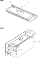
- Figure 2 – is the perspective view of the ice making unit related to an embodiment of the present invention.
- Figure 3 – is the partial view of the plate related to an embodiment of the present invention.
- Figure 4 – is the perspective view of the plate related to an embodiment of the present invention.
- Figure 5 – is the rear perspective view of the ice making unit related to an embodiment of the present invention.
- the refrigerator (1) comprises an ice making unit (6) that has an ice cube tray (2), a plate (3) situated above the ice cube tray (2) and covering the ice cube tray (2), a channel (4) situated on the plate (3) and providing the filling of the ice cube tray (2) with water for making ice cubes and a casing (5) enclosing the ice cube tray (2) and the plate (3).
- the ice making unit (6) comprises at least one first stopper (7) that protrudes from the inner surface thereof and that is inclined towards the ice cube tray (2).
- the water poured into the channel (4) flows towards the ice cube tray (2) by means of the inclined configuration of the first stopper (7) towards the ice cube tray (2).
- the water splattering from the ice cube tray (2) due to shocks or vibrations hits the surface facing the ice cube tray (2) of the first stopper (7) inside the channel (4) and refills the ice cube tray (2).
- the water is prevented from overflowing from the ice cube tray (2) and from freezing outside the ice cube tray (2).
- the first stopper (7) transversely extends between the side walls of the channel (4) so as to almost completely close the channel (4).
- the first stopper (7) is positioned so that an opening remains between one wall of the channel (4) and the first stopper (7) in order to fill water into the ice cube tray (2).
- the water splattering from the opening due to the movement of the ice cube tray (2) after filling the ice cube tray (2) hits the first stopper (7) and is guided back to the ice cube tray (2).
- the ice making unit (6) comprises at least one second stopper (8) that is positioned across from the first stopper (7) so that there is a level difference therebetween and that protrudes in an inclined manner from the channel (4) inner surface towards the ice cube tray (2).
- the second stopper (8) is positioned on the side wall of the channel (4) across from the side wall of the channel (4) from which the first stopper (7) protrudes so as to be one above the other and so that a gap remains between the first stopper (7) and the second stopper (8).
- the water is provided to be filled into the ice cube tray (2) in a more controlled manner. Moreover, the water that reaches the channel (4) surface due to any shock or vibration is obstructed by the first stopper (7) and the second stopper (8). Thus, the water hits the first stopper (7) and the second stopper (8) and refills the ice cube tray (2).
- the channel (4) is formed so as to protrude from the lower surface of the plate (3).
- the water flows from the channel (4) towards the ice cube tray (2) without splattering as if flowing from a tap.
- the water is prevented from splattering and freezing outside the ice cube tray (2).
- the channel (4) extends towards the ice cube tray (2) by narrowing.
- the channel (4) the cross-sectional area of which narrows as getting closer to the ice cube tray (2), the water flows in a more accelerated manner towards the ice cube tray (2).
- the casing (5) comprises at least one housing (9) and the plate (3) comprises at least one connection member (10) that enables the plate (3) to be rotatably mounted to the casing (5) by being seated into the housing (9).
- the ice cubes hit the plate (3), enabling the plate (3) to open easily while the ice cube tray (2) is being twisted.
- the plate (3) covering the ice cube tray (2) prevents the water from overflowing from the ice cube tray (2) due to any shock or vibration. Even if the water overflows from the ice cube tray (2), it hits the first stopper (7) and returns to the ice cube tray (2). Moreover, by means of the first stopper (7), the water is guided towards the ice cube tray (2) in a controlled manner.
Landscapes
- Engineering & Computer Science (AREA)
- Physics & Mathematics (AREA)
- Mechanical Engineering (AREA)
- Thermal Sciences (AREA)
- General Engineering & Computer Science (AREA)
- Production, Working, Storing, Or Distribution Of Ice (AREA)
- Devices That Are Associated With Refrigeration Equipment (AREA)
Abstract
The present invention relates to a refrigerator (1) comprising an ice making unit (6) that has an ice cube tray (2), a plate (3) situated above the ice cube tray (2) and covering the ice cube tray (2), a channel (4) situated on the plate (3) and providing the filling of the ice cube tray (2) with water for making ice cubes and a casing (5) enclosing the ice cube tray (2) and the plate (3).
Description
The present invention relates to a refrigerator comprising an ice making unit.
In refrigerators, the ice making process is composed of the steps of taking the water required for ice making from a source, pouring the water into the ice cube tray, and creating ice by benefiting from the heat transfer in the freezing compartment; thus the user is enabled to receive as much ice cubes as he/she wants at any time. The ice cube trays used in the ice making process are generally located in the freezing compartments of the refrigerators. In order to efficiently use the freezing compartment space, it is preferred to place the ice cube trays onto the freezing compartment door. However, opening/closing the freezing compartment door during ice making may cause the water not-yet frozen to overflow from the ice cube tray or to splatter into the freezing compartment.
In the state of the art International Patent Application No. WO2010058967, a water overflow reducing plate is disclosed, that covers the ice making tray to prevent water from overflowing from the ice making tray.
The aim of the present invention is the realization of a refrigerator comprising an ice making unit wherein the water is filled into the ice cube tray in a controlled manner and the water to be filled is prevented from overflowing from the ice cube tray.
The refrigerator realized in order to attain the aim of the present invention, explicated in the first claim and the respective claims thereof comprises an ice making unit that has an ice cube tray, a plate situated above the ice cube tray and covering the ice cube tray, a channel situated on the plate and providing the filling of the ice cube tray with water for making ice cubes and a casing enclosing the ice cube tray and the plate.
The ice cube tray comprises at least one first stopper that protrudes from the channel wall so as to stay inside the channel and that is inclined towards the ice cube tray. The first stopper inclined towards the ice cube tray guides the water towards the ice cube tray through the channel and enables it to be poured into the ice cube tray in a controlled manner. The first stopper limits the area through which the water leaves the channel and thus prevents the water splattered from the ice cube tray due to shocks or vibrations from leaving the channel.
In an embodiment of the present invention, the first stopper transversely extends between the side walls of the channel so as to almost completely close the channel. The first stopper is situated in the channel so as to leave an opening that allows the water to be filled into the ice cube tray. Thus, the water is filled into the ice cube tray in a controlled manner and the water is prevented from overflowing from the ice cube tray by means of the narrowness of the opening and the downwards inclined configuration of the first stopper.
In an embodiment of the present invention, the ice making unit comprises at least one second stopper that is positioned across from the first stopper so that there is a level difference therebetween and that protrudes in an inclined manner from the channel surface towards the ice cube tray. A water path is formed between the first stopper and the second stopper that are oppositely and consecutively placed onto the side walls of the channel. The water poured into the channel hits the first stopper and the second stopper respectively. Thus, the distance the water covers inside the channel is prolonged, the speed of the water is decreased and it is filled into the ice cube tray in a more controlled manner. Moreover, the water splattering from the ice cube tray due to any shock or vibration is prevented from leaving the channel by means of the first stopper and the second stopper.
In an embodiment of the present invention, the part of the channel facing the ice cube tray is formed so as to protrude towards the ice cube tray from under the plate. The protrusion shape extends linearly with respect to the ice cube tray. Thus the water flows through the channel towards the ice cube tray without splattering.
In an embodiment of the present invention, the channel extends towards the ice cube tray by narrowing. The channel being inclined towards the ice cube tray provides the water to quickly fill into the ice cube tray. The water fills into the ice cube tray before being crystallized with the effect of the cool air in the environment.
In an embodiment of the present invention, the casing comprises at least one housing and the plate comprises at least one connection member that enables the plate to be rotatably mounted to the casing by being seated into the housing. Thus, the ice cubes in the ice cube tray are taken out of the ice cube tray by at least partially opening the plate.
By means of the present invention, the water is guided towards the ice cube tray in a controlled manner, with a reduced speed by means of the first stopper and the water is prevented from overflowing from the ice cube tray due to any shock or vibration.
A refrigerator realized in order to attain the aim of the present invention is illustrated in the attached figures, where:
Figure 1 – is the schematic view of a refrigerator.
Figure 2 – is the perspective view of the ice making unit related to an embodiment of the present invention.
Figure 3 – is the partial view of the plate related to an embodiment of the present invention.
Figure 4 – is the perspective view of the plate related to an embodiment of the present invention.
Figure 5 – is the rear perspective view of the ice making unit related to an embodiment of the present invention.
The elements illustrated in the figures are numbered as follows:
- Refrigerator
- Ice cube tray
- Plate
- Channel
- Casing
- Ice making unit
- First stopper
- Second stopper
- Housing
- Connection member
The refrigerator (1) comprises an ice making unit (6) that has an ice cube tray (2), a plate (3) situated above the ice cube tray (2) and covering the ice cube tray (2), a channel (4) situated on the plate (3) and providing the filling of the ice cube tray (2) with water for making ice cubes and a casing (5) enclosing the ice cube tray (2) and the plate (3).
The ice making unit (6) comprises at least one first stopper (7) that protrudes from the inner surface thereof and that is inclined towards the ice cube tray (2). The water poured into the channel (4) flows towards the ice cube tray (2) by means of the inclined configuration of the first stopper (7) towards the ice cube tray (2). The water splattering from the ice cube tray (2) due to shocks or vibrations hits the surface facing the ice cube tray (2) of the first stopper (7) inside the channel (4) and refills the ice cube tray (2). Thus, the water is prevented from overflowing from the ice cube tray (2) and from freezing outside the ice cube tray (2).
In an embodiment of the present invention, the first stopper (7) transversely extends between the side walls of the channel (4) so as to almost completely close the channel (4). The first stopper (7) is positioned so that an opening remains between one wall of the channel (4) and the first stopper (7) in order to fill water into the ice cube tray (2). The water splattering from the opening due to the movement of the ice cube tray (2) after filling the ice cube tray (2) hits the first stopper (7) and is guided back to the ice cube tray (2).
In an embodiment of the present invention, the ice making unit (6) comprises at least one second stopper (8) that is positioned across from the first stopper (7) so that there is a level difference therebetween and that protrudes in an inclined manner from the channel (4) inner surface towards the ice cube tray (2). The second stopper (8) is positioned on the side wall of the channel (4) across from the side wall of the channel (4) from which the first stopper (7) protrudes so as to be one above the other and so that a gap remains between the first stopper (7) and the second stopper (8). Thus, the water flows over the first stopper (7) and the second stopper (8) in a cascading manner. The path the water covers in the channel (4) is prolonged and its speed is decreased. The water is provided to be filled into the ice cube tray (2) in a more controlled manner. Moreover, the water that reaches the channel (4) surface due to any shock or vibration is obstructed by the first stopper (7) and the second stopper (8). Thus, the water hits the first stopper (7) and the second stopper (8) and refills the ice cube tray (2).
In an embodiment of the present invention, the channel (4) is formed so as to protrude from the lower surface of the plate (3). Thus, the water flows from the channel (4) towards the ice cube tray (2) without splattering as if flowing from a tap. The water is prevented from splattering and freezing outside the ice cube tray (2).
In an embodiment of the present invention, the channel (4) extends towards the ice cube tray (2) by narrowing. By means of the channel (4) the cross-sectional area of which narrows as getting closer to the ice cube tray (2), the water flows in a more accelerated manner towards the ice cube tray (2).
In an embodiment of the present invention, the casing (5) comprises at least one housing (9) and the plate (3) comprises at least one connection member (10) that enables the plate (3) to be rotatably mounted to the casing (5) by being seated into the housing (9). When the ice making process is completed, the ice cubes hit the plate (3), enabling the plate (3) to open easily while the ice cube tray (2) is being twisted.
By means of the present invention, the plate (3) covering the ice cube tray (2) prevents the water from overflowing from the ice cube tray (2) due to any shock or vibration. Even if the water overflows from the ice cube tray (2), it hits the first stopper (7) and returns to the ice cube tray (2). Moreover, by means of the first stopper (7), the water is guided towards the ice cube tray (2) in a controlled manner.
It is to be understood that the present invention is not limited by the embodiments disclosed above and a person skilled in the art can easily introduce different embodiments. These should be considered within the scope of the protection postulated by the claims of the present invention.
Claims (6)
- A refrigerator (1) comprising an ice making unit (6) that has an ice cube tray (2), a plate (3) situated above the ice cube tray (2) and covering the ice cube tray (2), a channel (4) situated on the plate (3) and providing the filling of the ice cube tray (2) with water for making ice cubes and a casing (5) enclosing the ice cube tray (2) and the plate (3), characterized by the ice making unit (6) having at least one first stopper (7) that protrudes from the inner surface of the channel (4) and that is inclined towards the ice cube tray (2).
- A refrigerator (1) as in Claim 1, characterized by the first stopper (7) that transversely extends between the side walls of the channel (4) so as to almost completely close the channel (4).
- A refrigerator (1) as in Claim 1 or 2, characterized by the ice making unit (6) comprising at least one second stopper (8) that is positioned across from the first stopper (7) so that there is a level difference therebetween and that protrudes in an inclined manner from the channel (4) surface towards the ice cube tray (2).
- A refrigerator (1) as in any one of the above claims, characterized by the channel (4) that is formed so as to protrude from the lower surface of the plate (3).
- A refrigerator (1) as in any one of the above claims, characterized by the channel (4) that extends towards the ice cube tray (2) by narrowing.
- A refrigerator (1) as in any one of the above claims, characterized by the casing (5) comprising at least one housing (9) and by the plate (3) comprising at least one connection member (10) that enables the plate (3) to be rotatably mounted to the casing (5) by being seated into the housing (9).
Applications Claiming Priority (2)
| Application Number | Priority Date | Filing Date | Title |
|---|---|---|---|
| TRA2012/13594 | 2012-11-23 | ||
| TR201213594 | 2012-11-23 |
Publications (1)
| Publication Number | Publication Date |
|---|---|
| WO2014079705A1 true WO2014079705A1 (en) | 2014-05-30 |
Family
ID=49626909
Family Applications (1)
| Application Number | Title | Priority Date | Filing Date |
|---|---|---|---|
| PCT/EP2013/073380 Ceased WO2014079705A1 (en) | 2012-11-23 | 2013-11-08 | A refrigerator comprising an ice making unit |
Country Status (1)
| Country | Link |
|---|---|
| WO (1) | WO2014079705A1 (en) |
Cited By (2)
| Publication number | Priority date | Publication date | Assignee | Title |
|---|---|---|---|---|
| US10753666B2 (en) | 2014-10-06 | 2020-08-25 | Icebreaker Nordic Aps | Ice cube producing unit |
| US11493255B2 (en) | 2014-10-06 | 2022-11-08 | Icebreaker Nordic Aps | Ice cube producing unit |
Citations (5)
| Publication number | Priority date | Publication date | Assignee | Title |
|---|---|---|---|---|
| DE8305911U1 (en) * | 1982-03-09 | 1983-09-01 | N.V. Philips' Gloeilampenfabrieken, 5621 Eindhoven | ICE CUBE GENERATOR FOR A FRIDGE |
| WO2002052207A1 (en) * | 2000-12-22 | 2002-07-04 | Arçelik A.S. | Refrigerator |
| DE602004004552T2 (en) * | 2003-09-16 | 2007-10-31 | Multibrás S.A. Eletrodomésticos | ICE-FORM FEEDING SYSTEM FOR COOLING UNITS |
| DE102009046031A1 (en) * | 2009-10-27 | 2011-04-28 | BSH Bosch und Siemens Hausgeräte GmbH | Refrigerating appliance with ice maker |
| DE102011006858A1 (en) * | 2011-04-06 | 2012-10-11 | BSH Bosch und Siemens Hausgeräte GmbH | Eisstückbereitersystem and refrigeration device with such a Eisstückbereitersystem |
-
2013
- 2013-11-08 WO PCT/EP2013/073380 patent/WO2014079705A1/en not_active Ceased
Patent Citations (5)
| Publication number | Priority date | Publication date | Assignee | Title |
|---|---|---|---|---|
| DE8305911U1 (en) * | 1982-03-09 | 1983-09-01 | N.V. Philips' Gloeilampenfabrieken, 5621 Eindhoven | ICE CUBE GENERATOR FOR A FRIDGE |
| WO2002052207A1 (en) * | 2000-12-22 | 2002-07-04 | Arçelik A.S. | Refrigerator |
| DE602004004552T2 (en) * | 2003-09-16 | 2007-10-31 | Multibrás S.A. Eletrodomésticos | ICE-FORM FEEDING SYSTEM FOR COOLING UNITS |
| DE102009046031A1 (en) * | 2009-10-27 | 2011-04-28 | BSH Bosch und Siemens Hausgeräte GmbH | Refrigerating appliance with ice maker |
| DE102011006858A1 (en) * | 2011-04-06 | 2012-10-11 | BSH Bosch und Siemens Hausgeräte GmbH | Eisstückbereitersystem and refrigeration device with such a Eisstückbereitersystem |
Cited By (2)
| Publication number | Priority date | Publication date | Assignee | Title |
|---|---|---|---|---|
| US10753666B2 (en) | 2014-10-06 | 2020-08-25 | Icebreaker Nordic Aps | Ice cube producing unit |
| US11493255B2 (en) | 2014-10-06 | 2022-11-08 | Icebreaker Nordic Aps | Ice cube producing unit |
Similar Documents
| Publication | Publication Date | Title |
|---|---|---|
| JP5858678B2 (en) | refrigerator | |
| KR101376873B1 (en) | Refrigerator | |
| KR101410754B1 (en) | Deicing device and refrigerator having the same | |
| KR101705641B1 (en) | Refrigerator and method for assembling ice maker of refrigerator | |
| KR20120007202A (en) | Refrigerator | |
| KR20120018285A (en) | Refrigerator having ice making device | |
| KR101644181B1 (en) | A Ice Ball Manufacturing Unit and Method Thereof | |
| EP3441701B1 (en) | Refrigerator | |
| EP2706314B1 (en) | Ice tray for ice maker, ice maker and refrigerator having it | |
| US10746454B2 (en) | Household refrigeration appliance having a multiple-part external housing of an icemaker | |
| CN102597662A (en) | Refrigeration device comprising an ice maker | |
| CN102893105B (en) | Comprise the refrigerating appliance of ice machine | |
| WO2016037909A1 (en) | A cooling device wherein ice is obtained quickly | |
| KR20080006235U (en) | Ice maker and refrigerator with same | |
| KR20110016834A (en) | Refrigerator | |
| WO2014053356A1 (en) | A refrigerator | |
| WO2014076003A1 (en) | A refrigerator comprising an ice making unit | |
| KR101259526B1 (en) | Ice maker | |
| JPWO2020070770A1 (en) | refrigerator | |
| KR20120030270A (en) | Cool air supply structure of french type refrigerator | |
| WO2014161779A1 (en) | A cooling device comprising an ice cube tray | |
| KR20130071025A (en) | Refrigerator mounted with ice making apparatus | |
| KR101132481B1 (en) | An ice dispenser for refrigerator | |
| WO2016015900A1 (en) | A refrigerator comprising an ice making unit | |
| CN102597663A (en) | Ice maker |
Legal Events
| Date | Code | Title | Description |
|---|---|---|---|
| 121 | Ep: the epo has been informed by wipo that ep was designated in this application |
Ref document number: 13794833 Country of ref document: EP Kind code of ref document: A1 |
|
| NENP | Non-entry into the national phase |
Ref country code: DE |
|
| 122 | Ep: pct application non-entry in european phase |
Ref document number: 13794833 Country of ref document: EP Kind code of ref document: A1 |