WO2014077271A1 - Pneumatic tire - Google Patents
Pneumatic tire Download PDFInfo
- Publication number
- WO2014077271A1 WO2014077271A1 PCT/JP2013/080658 JP2013080658W WO2014077271A1 WO 2014077271 A1 WO2014077271 A1 WO 2014077271A1 JP 2013080658 W JP2013080658 W JP 2013080658W WO 2014077271 A1 WO2014077271 A1 WO 2014077271A1
- Authority
- WO
- WIPO (PCT)
- Prior art keywords
- groove
- tire
- land portion
- sipe
- circumferential
- Prior art date
Links
Images


Classifications
-
- B—PERFORMING OPERATIONS; TRANSPORTING
- B60—VEHICLES IN GENERAL
- B60C—VEHICLE TYRES; TYRE INFLATION; TYRE CHANGING; CONNECTING VALVES TO INFLATABLE ELASTIC BODIES IN GENERAL; DEVICES OR ARRANGEMENTS RELATED TO TYRES
- B60C11/00—Tyre tread bands; Tread patterns; Anti-skid inserts
- B60C11/03—Tread patterns
- B60C11/0306—Patterns comprising block rows or discontinuous ribs
-
- B—PERFORMING OPERATIONS; TRANSPORTING
- B60—VEHICLES IN GENERAL
- B60C—VEHICLE TYRES; TYRE INFLATION; TYRE CHANGING; CONNECTING VALVES TO INFLATABLE ELASTIC BODIES IN GENERAL; DEVICES OR ARRANGEMENTS RELATED TO TYRES
- B60C11/00—Tyre tread bands; Tread patterns; Anti-skid inserts
- B60C11/03—Tread patterns
- B60C11/12—Tread patterns characterised by the use of narrow slits or incisions, e.g. sipes
- B60C11/1236—Tread patterns characterised by the use of narrow slits or incisions, e.g. sipes with special arrangements in the tread pattern
-
- B—PERFORMING OPERATIONS; TRANSPORTING
- B60—VEHICLES IN GENERAL
- B60C—VEHICLE TYRES; TYRE INFLATION; TYRE CHANGING; CONNECTING VALVES TO INFLATABLE ELASTIC BODIES IN GENERAL; DEVICES OR ARRANGEMENTS RELATED TO TYRES
- B60C11/00—Tyre tread bands; Tread patterns; Anti-skid inserts
- B60C11/03—Tread patterns
- B60C11/13—Tread patterns characterised by the groove cross-section, e.g. for buttressing or preventing stone-trapping
- B60C11/1376—Three dimensional block surfaces departing from the enveloping tread contour
- B60C11/1392—Three dimensional block surfaces departing from the enveloping tread contour with chamfered block edges
-
- B—PERFORMING OPERATIONS; TRANSPORTING
- B60—VEHICLES IN GENERAL
- B60C—VEHICLE TYRES; TYRE INFLATION; TYRE CHANGING; CONNECTING VALVES TO INFLATABLE ELASTIC BODIES IN GENERAL; DEVICES OR ARRANGEMENTS RELATED TO TYRES
- B60C11/00—Tyre tread bands; Tread patterns; Anti-skid inserts
- B60C11/03—Tread patterns
- B60C2011/0337—Tread patterns characterised by particular design features of the pattern
- B60C2011/0339—Grooves
- B60C2011/0341—Circumferential grooves
- B60C2011/0348—Narrow grooves, i.e. having a width of less than 4 mm
-
- B—PERFORMING OPERATIONS; TRANSPORTING
- B60—VEHICLES IN GENERAL
- B60C—VEHICLE TYRES; TYRE INFLATION; TYRE CHANGING; CONNECTING VALVES TO INFLATABLE ELASTIC BODIES IN GENERAL; DEVICES OR ARRANGEMENTS RELATED TO TYRES
- B60C11/00—Tyre tread bands; Tread patterns; Anti-skid inserts
- B60C11/03—Tread patterns
- B60C2011/0337—Tread patterns characterised by particular design features of the pattern
- B60C2011/0339—Grooves
- B60C2011/0341—Circumferential grooves
- B60C2011/0351—Shallow grooves, i.e. having a depth of less than 50% of other grooves
-
- B—PERFORMING OPERATIONS; TRANSPORTING
- B60—VEHICLES IN GENERAL
- B60C—VEHICLE TYRES; TYRE INFLATION; TYRE CHANGING; CONNECTING VALVES TO INFLATABLE ELASTIC BODIES IN GENERAL; DEVICES OR ARRANGEMENTS RELATED TO TYRES
- B60C11/00—Tyre tread bands; Tread patterns; Anti-skid inserts
- B60C11/03—Tread patterns
- B60C2011/0337—Tread patterns characterised by particular design features of the pattern
- B60C2011/0386—Continuous ribs
- B60C2011/0393—Narrow ribs, i.e. having a rib width of less than 8 mm
- B60C2011/0395—Narrow ribs, i.e. having a rib width of less than 8 mm for linking shoulder blocks
Definitions
- the present invention relates to a pneumatic tire provided with a tread pattern.
- a tire having two intermediate land areas defined by a main groove is conventionally known (see Patent Document 1).
- lug grooves are provided in the region of the inner land portion and the region of the intermediate land portion, and the lug grooves in the two intermediate land portions extend inclining in the same direction with respect to the tire circumferential direction.
- the lug groove in the region of the inner land portion extends in a different direction from the lug groove in the region of the intermediate land portion with respect to the tire circumferential direction. According to the tire of Patent Document 1, the dry performance can be improved while maintaining the snow performance.
- the all-season tire is desirably provided with tire performance that can cope with various road surface conditions such as dry, wet, and snow.
- tire performance that can cope with various road surface conditions such as dry, wet, and snow.
- the balance between the wear resistance performance on the dry road surface, the wet performance and the snow performance is not sufficient. Specifically, if the wet turning performance and the snow handling stability performance are to be improved, the wear resistance performance on the dry road surface is lowered.
- the present invention provides a pneumatic tire having an excellent balance between wear resistance on a dry road surface, wet turning performance and snow handling stability.
- One embodiment of the present invention is a pneumatic tire including a bead, a sidewall, a belt layer, a carcass layer, and a tread portion having a tread pattern.
- the tread pattern is Four circumferential main grooves parallel to the tire circumferential direction, two outer circumferential main grooves arranged on the outer side in the tire width direction, and two inner sides sandwiched between the outer circumferential main grooves A circumferential main groove, a tire center line passes between the inner circumferential main grooves, and a circumferential main groove group; A region of an inner land portion defined by the two inner circumferential main grooves and through which the tire center line passes, and two intermediate lands defined by the outer circumferential main groove and the inner circumferential main groove A plurality of lug grooves that form a plurality of land portion blocks in the inner land portion and the intermediate land portion across a region of a portion; A circumferential shallow groove having a shallower groove depth than the circumferential main groove, which is provided in each of the regions of the
- the tire of the lug groove provided in each region of the intermediate land portion advances from the outer side in the tire width direction to the inner side in the tire width direction, the tire of the lug groove provided in the region of one intermediate land portion of the two intermediate land portions
- the direction of the groove inclination inclined with respect to the first direction in the circumferential direction is the first of the lug grooves provided in the region of the other intermediate land portion of the two intermediate land portions in the tire circumferential direction.
- the lug groove provided in each of the regions of the intermediate land portion has the same direction as the groove inclination inclined with respect to the second direction opposite to the direction at a position intersecting the circumferential shallow groove. Bending so that the groove slope approaches the tire circumferential direction.
- the lug groove provided in the inner land portion proceeds from the outer side in the tire width direction to the inner side in the tire width direction, the lug groove provided in each region of the intermediate land portion has a different groove inclination direction with respect to the tire circumferential direction. It extends to.
- Each of the intermediate land portions has a sipe extending in parallel with a lug groove provided in each of the intermediate land portions, and the sipe is connected to the inner circumferential main groove. It is preferable to block within the intermediate land portion without.
- the sipe extends in a zigzag shape while being displaced in a direction orthogonal to the extending direction of the sipe in a region inside the tire width direction with respect to the circumferential shallow groove, and the sipe extends from the tread surface of the sipe. It preferably extends in a zigzag shape toward the bottom while displacing in a direction orthogonal to the sipe depth direction toward the bottom of the sipe.
- the sipe extends linearly in a region outside in the tire width direction with respect to the circumferential shallow groove, and extends in a planar shape in a sipe depth direction from the tread surface of the sipe toward the bottom of the sipe. preferable.
- a shoulder land portion In the area outside the tire width direction of the circumferential main groove group, there is a shoulder land portion, In the region of the shoulder land portion, a shoulder lug groove extending from the outer side in the tire width direction toward the outer circumferential main groove is provided, and the shoulder lug groove is not connected to the outer circumferential main groove. It is preferable that the shoulder land portion forms a continuous land portion that extends continuously in the tire circumferential direction by closing in the middle.
- a shoulder land portion In the area outside the tire width direction of the circumferential main groove group, there is a shoulder land portion, In the region of the shoulder land portion, a shoulder lug groove extending from the outer side in the tire width direction toward the outer circumferential main groove is provided, It is preferable that the maximum groove width of the shoulder lug groove is wider than the maximum groove width of the lug groove provided in the region of the inner land portion and the intermediate land portion.
- the shoulder land portion is provided with a shoulder sipe extending from the outer side in the tire width direction toward the outer circumferential main groove,
- the shoulder sipe extends linearly in the extending direction of the shoulder sipe, and extends in a planar shape in a sipe depth direction from the tread surface of the shoulder sipe toward the bottom of the shoulder sipe; Displaced in a direction perpendicular to the sipe depth direction from the tread surface of the shoulder sipe toward the bottom of the shoulder sipe while displacing in a direction perpendicular to the extending direction of the shoulder sipe.
- a second portion extending in a zigzag shape toward the bottom, and the shoulder sipe moves from the first portion toward the outer circumferential main groove from the outer side in the tire width direction. It is preferable to end the process in place of
- chamfering is performed on a part of the edge portion in contact with the circumferential main groove of the inner land portion and the intermediate land portion.
- the width of the land portion in the region on the inner side in the tire width direction with respect to the circumferential shallow groove is equal to that in the region on the outer side in the tire width direction with respect to the circumferential shallow groove in the intermediate land portion. It is preferable that it is wider than the width of the land portion.
- the tire of the present invention has an excellent balance between wear resistance on a dry road surface, wet turning performance, and snow handling stability.
- the wet turning performance and the snow handling stability performance are excellent while maintaining the wear resistance performance on the dry road surface.
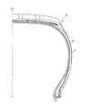
- FIG. 1 is an external view illustrating an entire tire according to an embodiment of the present invention.
- FIG. 2 is a half sectional view showing a part of the tire of FIG. 1. It is the figure which carried out the plane development view so that the tread pattern of the tire of an embodiment was easy to understand. It is a figure which expands and shows the tread pattern shown in FIG. 3 paying attention to an inner land part and a middle land part.
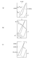
- (A) is a cross-sectional view of the tread surface of the tire according to the embodiment as seen in the direction of the Va-Va line shown in FIG.
- B is a cross-sectional view of the tread surface of the tire of the embodiment as seen in the direction of the Vb-Vb line shown in FIG.
- (A) is an enlarged view of the region A shown in FIG. 4
- (b) is an enlarged view of the region B shown in FIG. 4
- (c) is an enlarged view of the region C shown in FIG. FIG.
- FIG. 1 the external appearance of the pneumatic tire 1 which is one Embodiment of this invention is shown.
- a pneumatic tire (hereinafter referred to as a tire) 1 is a tire for a passenger car.
- known ones may be used, or new ones may be used, and there is no particular limitation in the present invention.
- the tire 1 includes a tread portion 2, sidewalls 3, beads 4, a carcass layer 5, and a belt layer 6.
- FIG. 2 is a half sectional view showing a part of the tire 1.
- the tire 1 has an inner liner layer and the like.
- the sidewall 3 and the bead 4 are disposed on both sides in the tire width direction so as to sandwich the tread portion 2 and form a pair.
- the tread portion 2, the bead 4, the belt layer 6, the inner liner layer and the like known ones may be used, or new ones may be used, and there is no particular limitation in the present invention.
- the tire 1 of the present invention has a tread pattern 10 that is a feature of the present invention formed in the tread portion.
- FIG. 3 is a plan development view of the tread pattern 10 of the tire 1 of the present invention in an easy-to-understand manner.
- the tire 1 having the tread pattern 10 can be suitably used for a passenger car tire.
- the dimensions of the circumferential main groove, lug groove, sipe, ground contact width, chamfer, circumferential direction shallow groove, shoulder lug groove, and land block, which will be described later, are numerical examples of passenger car tires.
- the mounting direction of the tire to be mounted toward the outside of the vehicle is predetermined.
- the symbol CL indicates the tire equator line.
- the region of the tread pattern 10 on the left side in FIG. 3 from the tire equator line CL is mounted on the vehicle inner side, and the region of the tread pattern 10 on the right side in FIG.
- the vehicle inner side and the vehicle outer side may be reversed and attached to the vehicle.
- the tread pattern 10 contacts the road surface in a tire width direction region indicated by a contact width 11w in a state where the tire 1 is mounted on the vehicle.
- region shown with a diagonal line in the tread pattern 10 is an area
- the grounding end is determined as follows. The tire width direction end portion of the contact surface when the tire 10 is assembled to a normal rim, filled with a normal internal pressure of 180 kPa, and brought into contact with a horizontal plane under the condition that the load is 88% of the normal load.
- the regular rim here refers to an “applied rim” defined in JATMA, a “Design Rim” defined in TRA, or a “Measuring Rim” defined in ETRTO.
- the normal internal pressure means “maximum air pressure” defined in JATMA, the maximum value of “TIRE LOAD LIMITS AT VARIOUS COLD INFLATION PRESSURES” defined in TRA, or “INFLATION PRESSURES” defined in ETRTO. 180 kPa when the tire is for a passenger car.
- the normal load means “maximum load capacity” defined in JATMA, the maximum value of “TIRE LOAD LIMITS AT VARIOUS COLD INFLATION PRESSURES” defined in TRA, or “LOAD CAPACITY” defined in ETRTO.
- the tire width direction refers to the rotation center axis direction of the tire 1
- the tire circumferential direction refers to the rotation direction of the rotation surface of the tread surface formed when the tire 1 is rotated around the tire rotation center axis.
- FIG. 3 shows these directions.
- the rotation direction of the tire is not particularly limited.
- the tire 1 of the present invention may be one in which pitches having the same dimensions in the tire circumferential direction are aligned with the tread pattern 10 shown in FIG. 3 in the tire circumferential direction. May be a plurality of pitches having different dimensions in the tire circumferential direction arranged in the tire circumferential direction.
- the tread pattern 10 includes a circumferential main groove group including four circumferential main grooves 11, 13, 15, 17 parallel to the tire circumferential direction, lug grooves 31, 33, 35, and circumferential shallow grooves 41, 43. And.
- the circumferential main groove group includes two outer circumferential main grooves 11 and 13 and two inner circumferential main grooves 15 and 17.
- the outer circumferential main grooves 11 and 13 are arranged on the outer side in the tire width direction with respect to the inner circumferential main grooves 15 and 17.
- the two inner circumferential main grooves 15 and 17 are disposed between the outer circumferential main grooves 11 and 13.
- a tire center line CL passes between the inner circumferential main groove 15 and the inner circumferential main groove 17 in the tire width direction.
- the groove depths of the outer circumferential main grooves 11 and 13 and the inner circumferential main grooves 15 and 17 are equal to each other, but may be different in other embodiments.
- the total amount of the groove widths of the outer circumferential main grooves 11 and 13 and the inner circumferential main grooves 15 and 17 is preferably 15 to 25% of the ground contact width 11w in terms of wet performance.
- the lug grooves 31, 33, and 35 are grooves that cross the region of the inner land portion 21 and the region of the intermediate land portions 23 and 25, and a plurality of lug grooves are provided at intervals in the tire circumferential direction.
- Each of the lug groove 31 and the lug grooves 33 and 35 may extend linearly or may be curved and extended gently.
- the groove widths 31w, 33w, and 35w of the lug grooves 31, 33, and 35 are all equal in the tire width direction, and are, for example, 2 to 7 mm.
- the inner land portion 21 is a portion formed by being defined by the two inner circumferential main grooves 15 and 17.
- the tire center line CL passes through the region of the inner land portion 21.
- the lug groove 31 forms a plurality of land portion blocks 22 in the tire circumferential direction in the region of the inner land portion 21. As shown in FIG. 4, the lug groove 31 extends at an inclination angle ⁇ ce with respect to the X2 direction in the tire circumferential direction.
- FIG. 4 is a partially enlarged view of the tread pattern 10.
- the inclination angle ⁇ ce is, for example, 60 to 85 degrees.
- the inclination angle ⁇ ce has an inclination angle closer to the tire width direction than the tire circumferential direction, high block rigidity of the land block 22 is ensured, and a small rudder during vehicle traveling is ensured. Wet turning performance at corners and snow handling stability are improved.
- the inclination angle ⁇ ce when the lug groove 31 is gently curved and extends is the width direction of the lug groove 31 at a portion where the lug groove 31 is connected to the inner circumferential main groove 15 and the inner circumferential main groove 17 respectively.
- the inclination with respect to the tire circumferential direction of the straight line which connects two points in the center position of a connection is represented.
- the intermediate land portion 23 is a portion formed by the outer circumferential main groove 11 and the inner circumferential main groove 15.
- the lug grooves 33 form a plurality of land portion blocks 24 in the tire circumferential direction in the region of the intermediate land portion 23.
- the intermediate land portion 25 is defined by the outer circumferential main groove 13 and the inner circumferential main groove 17, and is a portion formed between the outer circumferential main groove 13 and the inner circumferential main groove 17. is there.
- the lug groove 35 forms a plurality of land portion blocks 26 in the tire circumferential direction in the intermediate land portion 25.
- the lug groove 33 and the lug groove 35 are respectively directed to the X2 direction (the first direction in the tire circumferential direction) of one lug groove 33 when viewed from the outer side in the tire width direction toward the inner side in the tire width direction.
- the direction of the slanted groove is the same as the direction of the slanted groove with respect to the X1 direction (second direction opposite to the first direction in the tire circumferential direction) of the other lug groove 35.
- the lug groove 33 and the lug groove 35 are inclined in the same direction with respect to the X1 direction or the X2 direction in the tire circumferential direction.
- the groove inclination direction is in the range of ⁇ 90 degrees (90 degrees counterclockwise) to 90 degrees (90 degrees clockwise) with respect to the X1 direction or X2 direction of the tire circumferential direction. Represents the distinction between tilting in the range of 90 to 0 degrees or tilting in the range of 0 to 90 degrees, and grooves tilting in the same range have the same groove tilt direction and are different
- the grooves inclined in the angle range have different groove inclination directions.
- the above-mentioned lug groove 31 extends in a direction of groove inclination different from the lug grooves 33 and 35 with respect to the tire circumferential direction. Such a groove inclination direction ensures steering performance when turning left and right.
- the groove inclination is in the tire circumferential direction at a position P (see FIG. 4) where the lug groove 33 intersects the circumferential shallow groove 41. It is bent to approach. Specifically, as shown in FIG. 4, the lug groove 33 is inclined at the inclination angle ⁇ m1 with respect to the X2 direction at the outer side in the tire width direction from the position P, and is inclined at the inclination angle ⁇ m2 with respect to the X1 direction at the inner side in the tire width direction from the position P. Inclined. The inclination angle ⁇ m2 is smaller than the inclination angle ⁇ m1.
- the lug groove 33 is bent so that the groove inclination approaches the tire circumferential direction when viewed from the tire width direction outer side to the tire width direction inner side.
- the inclination angle ⁇ m1 of the groove inclination is, for example, 60 to 85 degrees.
- the inclination angle ⁇ m2 is, for example, 30 to 50 degrees.
- the lug groove 33 has two kinds of inclination angles, so that the turning is excellent even when turning from a small rudder angle to a medium rudder angle while the vehicle is traveling on a dry road surface, a wet road surface, and a snowy road surface. Performance and stable performance are obtained.
- the inclination angle ⁇ m1 when the inner portion of the lug groove 33 from the circumferential shallow groove 41 is gently curved and extended is the portion where the lug groove 33 is connected to the outer circumferential main groove 11 and the circumferential shallow groove 41, respectively.
- the inclination with respect to the tire circumferential direction of the straight line which connects the two points in the center position of the groove width direction of the lug groove 33 is represented.
- the inclination angle ⁇ m2 when the lug groove 33 is gently curved and extended is in the groove width direction of the lug groove 33 where the lug groove 33 is connected to each of the inner circumferential main groove 15 and the circumferential shallow groove 41.
- the inclination with respect to the tire circumferential direction of a straight line connecting two points at the center position is represented.
- the groove inclination is in the tire circumferential direction at a position Q (see FIG. 4) where the lug groove 35 intersects the circumferential shallow groove 43. It is bent to approach. Specifically, as shown in FIG. 4, the lug groove 35 is inclined at the inclination angle ⁇ m1 with respect to the X1 direction on the outer side in the tire width direction from the position Q, and is inclined with respect to the X2 direction at the inner side in the tire width direction from the position Q. The angle ⁇ m2 is inclined.
- the inclination angle ⁇ m1 when the inner portion of the lug groove 35 from the circumferential shallow groove 43 extends while being gently curved is connected to each of the inner circumferential main groove 17 and the circumferential shallow groove 43 with the lug groove 35.
- the inclination with respect to the tire circumferential direction of the straight line which connects two points in the center position of the groove width direction of the partial lug groove 35 is represented.
- the inclination angle ⁇ m2 when the lug groove 35 is gently curved and extended is in the groove width direction of the lug groove 35 where the lug groove 35 is connected to each of the inner circumferential main groove 17 and the circumferential shallow groove 43.
- the inclination angle on the outer side in the tire width direction from the position Q may be larger than the inclination angle on the inner side in the tire width direction from the position Q, and the inclination angle on the inner side in the tire width direction from the position Q. May be smaller than the inclination angle outside the position Q in the tire width direction.
- a region of the intermediate land portion 23 on the inner side in the tire width direction from the circumferential shallow groove 41 is wider in the tire width direction than the region on the outer side in the tire width direction from the circumferential shallow groove 41. It is preferable. From the same viewpoint, it is preferable that the region on the inner land portion 25 on the inner side in the tire width direction with respect to the circumferential shallow groove 43 is wider in the tire width direction than the region on the outer side in the tire width direction with respect to the circumferential shallow groove 43.
- the circumferential shallow grooves 41 and 43 are provided in the regions of the intermediate land portions 23 and 25, respectively, and extend in the tire circumferential direction.
- the circumferential shallow grooves 41, 43 are shallower than the circumferential main grooves 11, 13, 15, 17 and are raised to the bottom. Thereby, the wet turning performance is improved while ensuring the block rigidity in the intermediate land portions 23 and 25 and the wear resistance on the dry road surface.
- the groove depth of the circumferential shallow grooves 41, 43 is preferably within 70% of the groove depth of the circumferential main grooves 11, 13, 15, 17 from the viewpoint of ensuring wear resistance. % Is preferred.
- the groove widths of the circumferential shallow grooves 41 and 43 are preferably 5 to 15% of the length in the tire width direction of the intermediate land portions 23 and 25, respectively.
- the length in the tire width direction of the intermediate land portions 23 and 25 indicates the maximum length in the tire width direction of the land portion blocks 22 and 24 on the tread surface.
- the circumferential shallow grooves 41 and 43 are directed from the outer end in the tire width direction toward the inner end in the tire width direction, out of the entire area in the tire width direction of each of the intermediate land portions 23 and 25, for reasons of wear resistance. It is preferable to be provided at a position in the tire width direction when traveling along the tire width direction by 40% or more and less than 50% of the width of the intermediate land portions 23 and 25.
- the width of the land portion in the inner region in the tire width direction with respect to the circumferential shallow grooves 41 and 43 is the circumferential shallow groove 41 and 43 in the intermediate land portions 23 and 25.
- the circumferential direction shallow groove is not provided in the area
- the tread pattern 10 further includes sipes 34 and 36.
- a sipe has a width of less than 1.5 mm and a groove depth of less than 5 mm.
- the lug groove refers to a groove having a groove width of 1.5 mm or more and a groove depth of 5 mm or more.
- the sipes 34 and 36 are grooves extending in parallel with the lug grooves 33 and 35 in the regions of the intermediate land portions 23 and 25, respectively. Two sipes 34 and 36 are provided for each land block 24 and 26, respectively. In other embodiments, the number of sipes 34, 36 in one land block 24, 26 may be one or three or more.
- the sipes 34 and 36 are closed within the intermediate land portions 23 and 25 without being connected to the inner circumferential main grooves 15 and 17, respectively. Thereby, the abrasion resistance on the dry road surface becomes high.
- the sipes 34 and 36 extend in a zigzag shape while displacing in a direction orthogonal to the extending direction of the sipes 34 and 36 in the inner region in the tire width direction from the circumferential shallow grooves 41 and 43, respectively.
- the zigzag is displaced while being displaced in a direction (left and right direction in FIG. 5) perpendicular to the sipe depth direction from the tread surface to the bottom (direction from the lower side to the upper side in FIG. 5). Extending toward the bottom.
- FIG. 5A is a view taken along the line Va-Va shown in FIG. 3, and shows a state where the tread portion 2 is in contact with the horizontal plane.
- reference numerals shown in parentheses are reference numerals indicating elements in the area of the intermediate land portion 25 for convenience.
- the regions on the inner side in the tire width direction from the circumferential shallow grooves 41 and 43 of the land blocks 24 and 26 are compared with the outer side in the tire width direction from the circumferential shallow grooves 41 and 43, respectively, with respect to the tire circumferential direction of the lug grooves 33 and 35.
- the inclination angle is small and the rigidity is low. For this reason, the area inside the tire width direction with respect to the circumferential shallow groove 43 of the sipes 34, 36 is made to have the above three-dimensional shape, so that the block rigidity at the time of braking and driving is reinforced.
- Sipes 34 and 36 are connected to the outer circumferential main grooves 11 and 13, respectively.
- the sipes 34 and 36 extend linearly in regions outside the circumferential shallow grooves 41 and 43 in the tire width direction, respectively, and as shown in FIG. 5B, the sipe depths from the tread surface toward the bottom. It is preferable to extend planarly in the direction.
- Such a shape in the region outside the sipe 34, 36 in the tire width direction is hereinafter also referred to as a two-dimensional shape.
- FIG. 5B is a view taken along the line Vb-Vb shown in FIG. 3, and shows a state where the tread portion 2 is in contact with the horizontal plane.
- sipes 34 and 36 when they extend linearly, they do not include a zigzag extending shape, but include extending along a straight line, for example, gently curving and extending in a curved line. From this, when the sipes 34 and 36 extend in a planar shape, they include, for example, extending along a gently curved curved surface in addition to extending along a flat surface.
- the tread pattern 10 further has a sipe 32.
- the sipe 32 is a groove extending in parallel with the lug groove 31 in the region of the inner land portion 21. Two sipes 32 are provided for each land block 22. In other embodiments, one land block 22 or three or more may be provided per land block 22.
- the sipe 32 has a three-dimensional shape, which reinforces the block rigidity of the inner land portion 21 during braking / driving.
- the sipe 32 is connected to the inner circumferential main grooves 15 and 17. In another embodiment, the sipe 32 may have a two-dimensional shape, and may be blocked within the inner land portion 21 without being connected to the inner circumferential main grooves 15 and 17.
- the tread pattern 10 further has a shoulder land portion 51 in a region outside the outer circumferential main groove 11 in the tire width direction. Further, a shoulder land portion 53 is provided in a region on the outer side in the tire width direction of the outer circumferential main groove 13. In the regions of the shoulder land portions 51 and 53, shoulder lug grooves 61 and 63 extending from the outer side in the tire width direction toward the outer circumferential main grooves 11 and 13, respectively, are provided. The shoulder lug grooves 61 and 63 are closed on the way without being connected to the outer circumferential main grooves 11 and 13, respectively. Thereby, the shoulder land parts 51 and 53 form the continuous land part extended continuously in a tire peripheral direction.
- the shoulder land portions 51 and 53 have a high contribution to the braking performance and the turning performance, by forming such a continuous land portion, a decrease in the block rigidity of the shoulder land portions 51 and 53 can be suppressed, and dryness can be achieved. Abrasion resistance on the road surface is improved.
- the shoulder land portions 51 and 53 preferably form continuous land portions on the side in contact with the outer circumferential main grooves 11 and 13 in terms of securing wet turning performance and snow handling stability performance.
- the distance between the shoulder lug groove 61 and the outer circumferential main groove 11, that is, the width of the portion that connects two blocks adjacent in the tire circumferential direction to form a continuous land portion (connection width) ) Is preferably 5 to 20% of the length in the tire width direction between the outer circumferential main groove 11 and the ground contact end. In this embodiment, it is 15%, for example.
- the distance (connection width) between the shoulder lug groove 63 and the outer circumferential main groove 13 is 5 to 5 times the tire width direction length between the outer circumferential main groove 13 and the ground contact end. It is preferably 20%. In this embodiment, it is 15%, for example.
- the shoulder lug grooves 61 and 63 are tapered at the inner end in the tire width direction.
- the maximum groove widths 61w and 62w of the shoulder lug grooves 61 and 63 are wider than the groove widths (maximum groove widths) 31w, 33w and 35w of the lug grooves 31, 33 and 35, for example, 4 to 8 mm.
- the wide width of the shoulder land portions 51 and 53 having a high contribution during braking and driving improves wet turning performance and on-snow handling stability.
- the maximum groove width 61w of the shoulder lug groove 61 and the maximum groove width 63w of the shoulder lug groove 63 may be the same or different.
- the shoulder lug groove 61 extends with an inclination of ⁇ sh, for example, 75 to 90 degrees with respect to the X1 direction of the tire circumferential direction.
- the shoulder lug groove 63 extends with an inclination of ⁇ sh, for example, 75 to 90 degrees with respect to the X2 direction of the tire circumferential direction.
- the shoulder lug grooves 61 and 63 have an inclination angle close to the tire width direction with respect to the tire circumferential direction, so that high block rigidity is secured in the shoulder land portions 51 and 53 and a small steering angle. The wet turning performance and the stable operation performance on snow are improved. As shown in FIG.
- the inclination angle ⁇ sh of the shoulder lug grooves 61, 63 is different from the point of the middle position of the width of the shoulder lug groove 61, the groove 63 in the tire circumferential direction at the contact end, and the outer circumferential main groove 11, It represents with the inclination with respect to the tire circumferential direction of the straight line which connects the point of the intermediate position of the tire circumferential direction in the edge part of 13 side. Note that the inclination angles of the shoulder lug grooves 61 and 63 may be the same or different.
- sipes 62 and 64 are provided in the regions of the shoulder land portions 51 and 53, respectively. Two sipes 62 and 64 are provided between two shoulder lug grooves 61 and 63 adjacent in the tire circumferential direction. In another embodiment, the number of sipes 62 and 64 provided in the shoulder land portions 51 and 53 between the two adjacent shoulder lug grooves 61 and 63 may be one or three or more.
- the sipes 62 and 64 preferably have a three-dimensional shape on the inner side in the tire width direction from the ground contact end, and have a two-dimensional shape on the outer side in the tire width direction from the ground contact end.
- the sipes 62 and 64 have a three-dimensional shape on the inner side in the tire width direction from the ground contact end, the rigidity at the time of braking / driving of the shoulder land portions 51 and 53 can be increased.
- the sipes 62 and 64 extend linearly in the extending direction of the shoulder sipes 62 and 64, and extend in a planar shape in the sipe depth direction from the tread surface of the sipes 62 and 64 toward the bottom of the sipes 62 and 64.
- the two-dimensional shape part is changed to a three-dimensional shape part and the process ends. Since the sipes 62 and 64 have a three-dimensional shape on the side close to the outer circumferential main grooves 11 and 13, the rigidity during braking / driving of the shoulder land portions 51 and 53 can be increased.
- the tread pattern 10 further includes chamfers 21a, 23a, 25a, 51a, and 53a.
- a chamfer 21 a is applied to a part of the edge portion in contact with the inner circumferential main grooves 15, 17 of the inner land portion 21. Thereby, the edge amount of the inner land portion 21 is increased, and the wet turning performance and the snow handling stability performance are improved.
- the chamfer 21a is applied to a part of the edge portion, so that the block rigidity is not excessively lowered and the wear resistance on the dry road surface is ensured. As shown in FIG.
- the chamfers 21a are provided on both sides of each land portion block 22 in the tire width direction, and are processed so that the chamfering depth becomes larger toward the both sides in the tire circumferential direction.
- FIG. 6B is a diagram for explaining the chamfer 21a by enlarging a region surrounded by B shown in FIG.
- the depth of the chamfer 21a is preferably within 50% of the groove depth of the inner circumferential main grooves 15 and 17, and more preferably 10 to 30%, for reasons of wear resistance.
- FIG. 6C is a diagram for explaining the chamfer 25a by enlarging a region surrounded by C shown in FIG. In FIG.
- the reference numerals in parentheses indicate the elements in the region of the intermediate land portion 23 for convenience of explanation.
- the chamfer 23 a may be applied to an edge portion in contact with the inner circumferential main groove 15 of the intermediate land portion 23.
- the chamfer 25 a may be applied to an edge portion that contacts the inner circumferential main groove 17 of the intermediate land portion 25.
- the depth of the chamfers 23a, 25a is preferably within 50% of the groove depth of the circumferential main grooves 11, 13, 15, 17 for wear resistance reasons, and preferably 10-30%. .
- chamfers 51 a and 53 a are provided on part of the edges of the shoulder land portions 51 and 53 that are in contact with the outer circumferential main grooves 11 and 13, respectively. Thereby, the edge amounts of the shoulder land portions 51 and 53 are increased, and the wet turning performance and the snow handling stability performance are improved. Further, since chamfering 51a and 53a is performed on a part of the edge portion, the block rigidity is not excessively reduced, and wear resistance on the dry road surface is ensured. As shown in FIG. 4 and FIG. 6A, the chamfers 51a and 53a each have two surfaces with different inclinations adjacent to each other in the tire circumferential direction. FIG.
- FIG. 6A is a diagram for explaining the chamfer 51a by enlarging the area surrounded by A shown in FIG.
- reference numerals in parentheses indicate elements in the region of the shoulder land portion 53 for convenience of explanation.
- the depth of the chamfers 51a and 53a is preferably within 50% of the groove depth of the circumferential main grooves 11 and 13, and is preferably 10 to 30%.
- the groove depths of the outer circumferential main grooves 11, 13, 15, 17 may be equal to or different from each other.
- the maximum depth of the chamfers 21a, 23a, 25a, 51a, 53a may be equal or different from each other.
- the groove depths of the circumferential shallow grooves 41 and 43 may be equal to or different from each other.
- the maximum widths of the land blocks 24, 26 may be equal or different from each other.
- the tread pattern 10 has four circumferential main grooves 11, 13, 15, 17, a lug groove 31 and a sipe 32 in the region of the inner land portion 21,
- the lug grooves 33 and 35 and the sipes 34 and 36 are inclined in the same direction with respect to one side in the tire circumferential direction, and the lug grooves 33 and 35 are formed on the inner land portion.
- the lug grooves 31 provided in the region 21 are inclined in the opposite direction to the tire circumferential direction, and the lug grooves 33 and 35 are at positions P and Q where they intersect the circumferential shallow grooves 41 and 43, respectively. Since the groove slope is bent so as to approach the tire circumferential direction, wet turning performance and snow handling stability performance are improved. Further, when the configuration of the shoulder lug grooves 61, 63 is added to the configuration of the lug grooves 31, 33, 35, the tread pattern 10 has grooves of various orientations and inclination angles. Steering stability is further improved. Further, since the circumferential land shallow grooves 41 and 43 having a shallower groove depth than the circumferential main grooves 11, 13, 15, and 17 are provided in the regions of the intermediate land portions 23 and 25, wear resistance is increased. Sex is secured.
- Sipes 34 and 36 are provided in the regions of the intermediate land portions 23 and 25, respectively, and these sipes 34 and 36 are closed in the intermediate land portions 23 and 25 without being connected to the inner circumferential main grooves 15 and 17, respectively. This ensures wear resistance on the dry road surface. Since the sipes 34 and 36 have a three-dimensional shape in the inner region in the tire width direction with respect to the circumferential shallow grooves 41 and 43, the block rigidity at the time of braking and driving becomes higher.
- the block rigidity of the shoulder land portions 51 and 53 can be secured, and the wear resistance on the dry road surface Will improve. Moreover, while preventing the block rigidity of the shoulder land portions 51 and 53 from being lowered, wear resistance on the dry road surface is ensured. Since the maximum groove width of the shoulder lug grooves 61, 63 is wider than the groove width of the lug grooves 31, 33, 35, wet turning performance and on-snow handling stability performance are improved. Since chamfering is performed on a part of the edge portions in the tire width direction of the inner land portion 21 and the intermediate land portions 23 and 25, the edge amount increases, and wet turning performance and on-snow maneuvering stability performance are improved.
- the sipes 34 and 36 may not be parallel to the lug grooves 33 and 35.
- the sipes 34 and 36 may be connected to the outer circumferential main grooves 11 and 13.
- the sipes 34 and 36 may be closed in the intermediate land portions 23 and 25 without being connected to the inner circumferential main grooves 15 and 17.
- the tread pattern 10 may not have the sipes 34 and 36.
- the sipes 34 and 36 may have a two-dimensional shape on the inner side and a three-dimensional shape on the outer side with respect to the circumferential shallow grooves 41 and 43, respectively, or three-dimensional shapes on both the inner and outer sides.
- the sipes 34 and 36 may be provided only on one side with respect to the circumferential shallow grooves 41 and 43.
- the shoulder lug grooves 61 and 63 may be connected to the outer circumferential main grooves 11 and 13, and a plurality of land blocks may be formed in the tire circumferential direction.
- the tread pattern 10 may not have the shoulder land portions 61 and 63.
- the width of the shoulder lug grooves 61, 63 may be equal to or smaller than the width of the lug grooves 31, 33, 35.
- the number of circumferential main grooves is not limited to four, and may be five or more. In this case, three or more inner circumferential main grooves may be included.
- Example 10 In order to investigate the effect of the tread pattern 10 of the tire 1 of the present invention, a tire was manufactured as a prototype.
- the tire size was P265 / 70R17 113T.
- the rim was 17 ⁇ 7.5 J, and a tire provided with a tread pattern having the specifications shown in Table 1 and Table 2 below was produced.
- an FF vehicle having an engine displacement of 2 liters was used as a test vehicle.
- the internal pressure condition was 230 (kPa) for both the front and rear wheels.
- wet turning performance and snow handling stability performance were evaluated as follows.
- the test vehicle was run on a turning circuit of R30 (radius 30 m) at the limit speed for 5 laps, and the average lateral acceleration at that time was It was measured.
- the evaluation was performed by using the reciprocal of the measured value, and indicated by an index with the reciprocal of the measured value of the conventional tire as 100. The larger the index value, the better the wet turning performance.
- the on-snow maneuvering stability performance was measured in the same manner as the above-described wet turning performance measurement except that the on-snow road surface was replaced with a wet road surface having a water film having a water depth of 1 mm and the road surface was traveled on the snow.
- the evaluation was performed by using the reciprocal of the measured value, and indicated by an index with the reciprocal of the measured value of the conventional tire as 100. The larger the index value, the better the steering stability performance on snow.
- the wear resistance the amount of wear was measured after traveling 2000 km on a public road.
- the evaluation was performed by using the reciprocal of the measured value, and indicated by an index with the reciprocal of the measured value of the conventional tire as 100. The larger the index value, the better the wear resistance performance.
- Non-parallel means that the direction in which the sipe extends is opposite to the direction in which the lug groove in the same intermediate land region extends and the tire width direction.
- Parallel means that the direction in which the sipe extends is the same direction as the direction in which the lug groove extends in the region of the same intermediate land and the tire width direction.
- the groove depth of the circumferential shallow groove means a ratio (%) to the groove depth of the circumferential main groove.
- Whether or not the shoulder lug groove is closed is whether the shoulder lug grooves 61 and 63 are blocked in the middle without being connected to the outer circumferential main grooves 11 and 13 or are connected to the outer circumferential main grooves 11 and 13. Say. In Example 3, all the sipes in the middle land portion have a two-dimensional shape.
Abstract
Description
本発明は、ドライ路面での耐摩耗性能と、ウェット旋回性能および雪上操縦安定性能とのバランスに優れた空気入りタイヤを提供する。 The all-season tire is desirably provided with tire performance that can cope with various road surface conditions such as dry, wet, and snow. However, in the tire of
The present invention provides a pneumatic tire having an excellent balance between wear resistance on a dry road surface, wet turning performance and snow handling stability.
前記トレッドパターンは、
タイヤ周方向に並行する4本の周方向主溝であって、タイヤ幅方向の外側に配置された2本の外側周方向主溝と、前記外側周方向主溝に挟まれた2本の内側周方向主溝とを含み、前記内側周方向主溝の間をタイヤセンターラインが通る、周方向主溝群と、
前記2本の内側周方向主溝により画され、前記タイヤセンターラインが通過する内側陸部の領域、及び、前記外側周方向主溝と前記内側周方向主溝とにより画された2つの中間陸部の領域を横切って、前記内側陸部及び前記中間陸部に複数の陸部ブロックを形成させる複数のラグ溝と、
前記中間陸部の領域のそれぞれに設けられ、タイヤ周方向に延びる、前記周方向主溝に比べて溝深さの浅い周方向浅溝と、を含む。
前記中間陸部の領域のそれぞれに設けられるラグ溝がタイヤ幅方向外側からタイヤ幅方向内側に進むとき、前記2つの中間陸部のうち一方の中間陸部の領域に設けられるラグ溝の、タイヤ周方向のうち第1の方向に対して傾斜する溝傾斜の向きは、前記2つの中間陸部のうち他方の中間陸部の領域に設けられるラグ溝の、タイヤ周方向のうち前記第1の方向と逆方向の第2の方向に対して傾斜する溝傾斜の向きと同じであり、かつ、前記中間陸部の領域のそれぞれに設けられるラグ溝は、前記周方向浅溝と交差する位置で溝傾斜がタイヤ周方向に近づくように屈曲する。
前記内側陸部に設けられるラグ溝は、タイヤ幅方向外側からタイヤ幅方向内側に進むとき、前記中間陸部のそれぞれの領域に設けられるラグ溝と、タイヤ周方向に対して異なる溝傾斜の向きに延びる。 One embodiment of the present invention is a pneumatic tire including a bead, a sidewall, a belt layer, a carcass layer, and a tread portion having a tread pattern.
The tread pattern is
Four circumferential main grooves parallel to the tire circumferential direction, two outer circumferential main grooves arranged on the outer side in the tire width direction, and two inner sides sandwiched between the outer circumferential main grooves A circumferential main groove, a tire center line passes between the inner circumferential main grooves, and a circumferential main groove group;
A region of an inner land portion defined by the two inner circumferential main grooves and through which the tire center line passes, and two intermediate lands defined by the outer circumferential main groove and the inner circumferential main groove A plurality of lug grooves that form a plurality of land portion blocks in the inner land portion and the intermediate land portion across a region of a portion;
A circumferential shallow groove having a shallower groove depth than the circumferential main groove, which is provided in each of the regions of the intermediate land portion and extends in the tire circumferential direction.
When the lug groove provided in each region of the intermediate land portion advances from the outer side in the tire width direction to the inner side in the tire width direction, the tire of the lug groove provided in the region of one intermediate land portion of the two intermediate land portions The direction of the groove inclination inclined with respect to the first direction in the circumferential direction is the first of the lug grooves provided in the region of the other intermediate land portion of the two intermediate land portions in the tire circumferential direction. The lug groove provided in each of the regions of the intermediate land portion has the same direction as the groove inclination inclined with respect to the second direction opposite to the direction at a position intersecting the circumferential shallow groove. Bending so that the groove slope approaches the tire circumferential direction.
When the lug groove provided in the inner land portion proceeds from the outer side in the tire width direction to the inner side in the tire width direction, the lug groove provided in each region of the intermediate land portion has a different groove inclination direction with respect to the tire circumferential direction. It extends to.
前記ショルダー陸部の領域には、タイヤ幅方向外側から前記外側周方向主溝に向かって延在するショルダーラグ溝が設けられ、前記ショルダーラグ溝は、前記外側周方向主溝に接続することなく途中で閉塞することにより、前記ショルダー陸部は、タイヤ周方向に連続して延在する連続陸部を形成することが好ましい。 Furthermore, in the area outside the tire width direction of the circumferential main groove group, there is a shoulder land portion,
In the region of the shoulder land portion, a shoulder lug groove extending from the outer side in the tire width direction toward the outer circumferential main groove is provided, and the shoulder lug groove is not connected to the outer circumferential main groove. It is preferable that the shoulder land portion forms a continuous land portion that extends continuously in the tire circumferential direction by closing in the middle.
前記ショルダー陸部の領域には、タイヤ幅方向外側から前記外側周方向主溝に向かって延在するショルダーラグ溝が設けられ、
前記ショルダーラグ溝の最大溝幅は、前記内側陸部及び前記中間陸部の領域に設けられるラグ溝の最大溝幅に比べて広いことが好ましい。 Furthermore, in the area outside the tire width direction of the circumferential main groove group, there is a shoulder land portion,
In the region of the shoulder land portion, a shoulder lug groove extending from the outer side in the tire width direction toward the outer circumferential main groove is provided,
It is preferable that the maximum groove width of the shoulder lug groove is wider than the maximum groove width of the lug groove provided in the region of the inner land portion and the intermediate land portion.
前記ショルダーサイプは、前記ショルダーサイプの延在方向に線状に延び、かつ、前記ショルダーサイプのトレッド表面から前記ショルダーサイプの底部に向かうサイプ深さ方向に平面状に延びる第1の部分と、前記ショルダーサイプの延在方向に対して直交する方向に変位しながらジグザグ状に延び、かつ、前記ショルダーサイプのトレッド表面から前記ショルダーサイプの底部に向かうサイプ深さ方向に対して直交する方向に変位しながらジグザク状に前記底部に向かって延びる第2の部分と、を含み、前記ショルダーサイプは、タイヤ幅方向外側から前記外側周方向主溝に向かって進むとき、前記第1の部分から前記第2の部分に変わり終了する、ことが好ましい。 The shoulder land portion is provided with a shoulder sipe extending from the outer side in the tire width direction toward the outer circumferential main groove,
The shoulder sipe extends linearly in the extending direction of the shoulder sipe, and extends in a planar shape in a sipe depth direction from the tread surface of the shoulder sipe toward the bottom of the shoulder sipe; Displaced in a direction perpendicular to the sipe depth direction from the tread surface of the shoulder sipe toward the bottom of the shoulder sipe while displacing in a direction perpendicular to the extending direction of the shoulder sipe. A second portion extending in a zigzag shape toward the bottom, and the shoulder sipe moves from the first portion toward the outer circumferential main groove from the outer side in the tire width direction. It is preferable to end the process in place of
図1に、本発明の一実施形態である空気入りタイヤ1の外観を示す。
空気入りタイヤ(以下、タイヤという)1は、乗用車用タイヤである。
本発明のタイヤ1の構造及びゴム部材は、公知のものが用いられてもよいし、新規なものが用いられてもよく、本発明において、特に限定されない。 Hereinafter, the pneumatic tire of the present invention will be described in detail.
In FIG. 1, the external appearance of the
A pneumatic tire (hereinafter referred to as a tire) 1 is a tire for a passenger car.
As the structure and rubber member of the
トレッド部2、ビード4、ベルト層6、インナライナ層等は、公知のものが用いられてもよいし、新規なものが用いられてもよく、本発明において、特に限定されない。 As shown in FIG. 2, the
As the
ここで、接地端は以下のように定められる。タイヤ10を正規リムに組み付け、正規内圧180kPaを充填し、正規荷重の88%を負荷荷重とした条件において水平面に接地させたときの接地面のタイヤ幅方向端部である。なお、ここでいう正規リムとは、JATMAに規定される「適用リム」、TRAに規定される「Design Rim」、あるいはETRTOに規定される「Measuring Rim」をいう。また、正規内圧とは、JATMAに規定される「最高空気圧」、TRAに規定される「TIRE LOAD LIMITS AT VARIOUS COLD INFLATION PRESSURES」の最大値、あるいはETRTOに規定される「INFLATION PRESSURES」をいうが、タイヤが乗用車用である場合は180kPaとする。また、正規荷重とは、JATMAに規定される「最大負荷能力」、TRAに規定される「TIRE LOAD LIMITS AT VARIOUS COLD INFLATION PRESSURES」の最大値、あるいはETRTOに規定される「LOAD CAPACITY」をいう。 The tread pattern 10 contacts the road surface in a tire width direction region indicated by a
Here, the grounding end is determined as follows. The tire width direction end portion of the contact surface when the tire 10 is assembled to a normal rim, filled with a normal internal pressure of 180 kPa, and brought into contact with a horizontal plane under the condition that the load is 88% of the normal load. The regular rim here refers to an “applied rim” defined in JATMA, a “Design Rim” defined in TRA, or a “Measuring Rim” defined in ETRTO. In addition, the normal internal pressure means “maximum air pressure” defined in JATMA, the maximum value of “TIRE LOAD LIMITS AT VARIOUS COLD INFLATION PRESSURES” defined in TRA, or “INFLATION PRESSURES” defined in ETRTO. 180 kPa when the tire is for a passenger car. The normal load means “maximum load capacity” defined in JATMA, the maximum value of “TIRE LOAD LIMITS AT VARIOUS COLD INFLATION PRESSURES” defined in TRA, or “LOAD CAPACITY” defined in ETRTO.
本発明のタイヤ1は、図3に示すトレッドパターン10とタイヤ周方向に寸法の等しいいピッチをタイヤ周方向に並べたものであってもよく、ピッチバリエーションを施すために、トレッドパターン10とは、タイヤ周方向に寸法の異なる複数種のピッチをタイヤ周方向に並べたものであってもよい。 In the present invention, the tire width direction refers to the rotation center axis direction of the
The
周方向主溝群は、2本の外側周方向主溝11,13と、2本の内側周方向主溝15,17とを含む。外側周方向主溝11,13は、内側周方向主溝15,17に対して、タイヤ幅方向の外側に配置されている。2本の内側周方向主溝15,17は、外側周方向主溝11,13に挟まれて配置されている。タイヤ幅方向における内側周方向主溝15と内側周方向主溝17との間には、タイヤセンターラインCLが通っている。外側周方向主溝11,13及び内側周方向主溝15,17の溝深さは、互いに等しいが、他の実施形態では異なってもよい。外側周方向主溝11,13及び内側周方向主溝15,17の各溝幅の合計量は、ウェット性能の点で、接地幅11wの15~25%であるのが好ましい。 (Circumferential groove group)
The circumferential main groove group includes two outer circumferential
ラグ溝31,33,35は、内側陸部21の領域、および、中間陸部23,25の領域を横切る溝であり、それぞれタイヤ周方向に間隔をあけて複数設けられている。ラグ溝31,ラグ溝33,35は、それぞれ、直線的に延びていてもよく、緩やかに湾曲して延びていてもよい。ラグ溝31,33,35の溝幅31w,33w,35wは、いずれもタイヤ幅方向にわたって等しく、例えば、2~7mmである。 (Lug groove)
The
内側陸部21は、2本の内側周方向主溝15,17により画されることで形成された部分である。内側陸部21の領域には、タイヤセンターラインCLが通過する。ラグ溝31は、内側陸部21の領域に、タイヤ周方向に複数の陸部ブロック22を形成する。ラグ溝31は、図4に示すように、タイヤ周方向のX2方向に対して傾斜角θce傾斜して延びている。図4は、トレッドパターン10を一部拡大して示す図である。傾斜角θceは、例えば、60~85度である。このように傾斜角θceが、タイヤ周方向に比べて、タイヤ幅方向に近い傾斜角を有していることにより、陸部ブロック22の高いブロック剛性が確保されるとともに、車両走行中の小舵角でのウェット旋回性能および雪上操縦安定性能が向上する。なお、ラグ溝31が緩やかに湾曲して延びる場合の傾斜角θceは、ラグ溝31が、内側周方向主溝15および内側周方向主溝17とそれぞれ接続する部分のラグ溝31の幅方向の接続の中心位置にある2つの点を結ぶ直線のタイヤ周方向に対する傾きを表す。 Here, the
The
一方、上述のラグ溝31は、ラグ溝33,35とは、タイヤ周方向に対して異なる溝傾斜の向きに延びる。このような溝傾斜の向きによって、左右旋回時の操縦性能が確保される。 The
On the other hand, the above-mentioned
周方向浅溝41,43は、それぞれ、中間陸部23,25の領域に設けられ、タイヤ周方向に延びる。周方向浅溝41,43は、周方向主溝11,13,15,17と比べて、溝深さが浅く、底上げされている。これにより、中間陸部23,25でのブロック剛性およびドライ路面での耐摩耗性が確保されつつ、ウェット旋回性能が向上する。周方向浅溝41,43の溝深さは、耐摩耗性を確保する観点から、周方向主溝11,13,15,17の溝深さの70%以内であることが好ましく、30~50%であることが好ましい。
また、周方向浅溝41,43の溝幅は、それぞれ、中間陸部23,25のタイヤ幅方向長さの5~15%であることが好ましい。なお、中間陸部23,25のタイヤ幅方向長さは、トレッド表面における、陸部ブロック22,24のタイヤ幅方向の最大長さを指す。また、周方向浅溝41,43は、耐摩耗性の理由から、中間陸部23,25それぞれのタイヤ幅方向の全域のうち、タイヤ幅方向外側の端からタイヤ幅方向内側の端に向かって中間陸部23,25の幅の40%以上50%未満、タイヤ幅方向に沿って進んだときのタイヤ幅方向の位置に設けられていることが好ましい。すなわち、中間陸部23,25のうち、周方向浅溝41,43に対してタイヤ幅方向内側の領域における陸部の幅は、中間陸部23,25のうち、周方向浅溝41,43に対してタイヤ幅方向外側の領域における陸部の幅に比べて広いことが好ましい。
なお、内側陸部21の領域、および、後述するショルダー陸部51,53の領域には、周方向浅溝は設けられないことが好ましい。これら陸部21,51,53は、制駆動時のウェット旋回性能および雪上操縦安定性能への寄与が高く、周方向浅溝を設けると、ウェット旋回性能とドライ路面での耐摩耗性能との両立を図ることができないためである。 (Circumferential shallow groove)
The circumferential
The groove widths of the circumferential
In addition, it is preferable that the circumferential direction shallow groove is not provided in the area | region of the
トレッドパターン10は、さらに、サイプ34,36を有する。
本発明において、サイプは幅1.5mm未満であり、溝深さが5mm未満のものをいう。また、ラグ溝とは、溝幅が1.5mm以上であり、溝深さが5mm以上のものをいう。
サイプ34,36は、中間陸部23,25の領域のそれぞれにおいて、ラグ溝33,35と並行するように延在する溝である。サイプ34,36は、それぞれ、1つの陸部ブロック24,26につき、2本設けられている。なお、他の実施形態では、1つの陸部ブロック24,26におけるサイプ34,36の数は、1本又は3本以上設けられてもよい。 (Sipe)
The tread pattern 10 further includes
In the present invention, a sipe has a width of less than 1.5 mm and a groove depth of less than 5 mm. The lug groove refers to a groove having a groove width of 1.5 mm or more and a groove depth of 5 mm or more.
The
陸部ブロック24,26それぞれの、周方向浅溝41,43よりタイヤ幅方向内側の領域は、周方向浅溝41,43よりタイヤ幅方向外側と比べ、ラグ溝33,35のタイヤ周方向に対する傾斜角が小さく、剛性が低くなっている。このため、サイプ34,36の周方向浅溝43よりタイヤ幅方向内側の領域を上記の3次元形状とすることで、制動時および駆動時のブロック剛性が補強されるようにしている。 The
The regions on the inner side in the tire width direction from the circumferential
サイプ32は、内側陸部21の領域においてラグ溝31と並行するように延在する溝である。サイプ32は、1つの陸部ブロック22につき、2本設けられている。なお、他の実施形態では、1つの陸部ブロック22につき、1本又は3本以上設けられてもよい。サイプ32は、3次元形状であり、これにより、制駆動時における内側陸部21のブロック剛性が補強される。サイプ32は、内側周方向主溝15,17と接続する。なお、他の実施形態では、サイプ32は、2次元形状であってもよく、また、内側周方向主溝15,17と接続することなく内側陸部21内で閉塞してもよい。 The tread pattern 10 further has a
The
トレッドパターン10は、さらに、外側周方向主溝11のタイヤ幅方向外側の領域にショルダー陸部51を有している。また、外側周方向主溝13のタイヤ幅方向外側の領域にショルダー陸部53を有する。
ショルダー陸部51,53の領域には、それぞれ、タイヤ幅方向外側から外側周方向主溝11,13に向かって延在するショルダーラグ溝61,63が設けられている。ショルダーラグ溝61,63は、それぞれ、外側周方向主溝11,13に接続することなく途中で閉塞している。これにより、ショルダー陸部51,53は、タイヤ周方向に連続して延在する連続陸部を形成する。ショルダー陸部51,53は、制動性能および旋回性能への寄与が高いことから、このような連続陸部を形成することにより、ショルダー陸部51,53のブロック剛性の低下が抑えられるとともに、ドライ路面における耐摩耗性が向上する。なお、ショルダー陸部51,53は、ウェット旋回性能および雪上操縦安定性能を確保できる点で、外側周方向主溝11,13と接する側において連続陸部を形成することが好ましい。
なお、ショルダー陸部51の領域において、ショルダーラグ溝61と外側周方向主溝11との距離、すなわちタイヤ周方向に隣接する2つのブロックを連結して連続陸部としている部分の幅(連結幅)は、外側周方向主溝11と接地端とのタイヤ幅方向の長さの5~20%であることが好ましい。本実施形態では、例えば、15%である。同様に、ショルダー陸部53の領域において、ショルダーラグ溝63と外側周方向主溝13との距離(連結幅)は、外側周方向主溝13と接地端とのタイヤ幅方向長さの5~20%であることが好ましい。本実施形態では、例えば、15%である。 (Shoulder land)
The tread pattern 10 further has a
In the regions of the
In the region of the
ショルダーラグ溝61は、タイヤ周方向のX1方向に対してθsh、例えば、75~90度傾斜して延びる。また、ショルダーラグ溝63は、タイヤ周方向のX2方向に対してθsh、例えば、75~90度傾斜して延びる。このようにショルダーラグ溝61,63が、タイヤ周方向に対して、タイヤ幅方向に近い傾斜角を有することにより、ショルダー陸部51,53における高いブロック剛性が確保されるとともに、小舵角でのウェット旋回性能および雪上操縦安定性能が向上する。ショルダーラグ溝61,63の傾斜角θshは、図4に示すように、接地端でのタイヤ周方向におけるショルダーラグ溝61,溝63の幅の中間位置の点と、外側周方向主溝11,13の側の端部におけるタイヤ周方向の中間位置の点とを結ぶ直線の、タイヤ周方向に対する傾きで表す。なお、ショルダーラグ溝61,63同士の傾斜角は、等しくてもよく、異なっていてもよい。 The
The
あるいは、サイプ62,64は、ショルダーサイプ62,64の延在方向に線状に延び、かつ、サイプ62,64のトレッド表面からサイプ62,64の底部に向かうサイプ深さ方向に平面状に延びる、2次元形状の部分(第1の部分)と、サイプ62,64の延在方向に対して直交する方向に変位しながらジグザグ状に延び、かつ、サイプ62,64のトレッド表面からサイプ62,64の底部に向かうサイプ深さ方向に対して直交する方向に変位しながらジグザク状に底部に向かって延びる3次元形状の部分(第2の部分)と、を含み、サイプ62,64は、タイヤ幅方向外側から外側周方向主溝11,13に向かって進むとき、2次元形状の部分から3次元形状の部分に変わり終了する、ことが好ましい。サイプ62,64が、外側周方向主溝11,13に近い側で3次元形状であることにより、ショルダー陸部51,53の制駆動時の剛性を高めることができる。 Further,
Alternatively, the
トレッドパターン10は、さらに、面取り21a,23a,25a,51a,53aを有している。
図4に示すように、内側陸部21の内側周方向主溝15,17と接するエッジ部の一部には、面取り21aが施されている。これにより、内側陸部21のエッジ量が増し、ウェット旋回性能および雪上操縦安定性能が向上する。一方、面取り21aが施されるのは、エッジ部の一部であるため、ブロック剛性が過度に低下することがなく、ドライ路面での耐摩耗性が確保される。
面取り21aは、図6(b)に示すように、各陸部ブロック22のタイヤ幅方向の両側に設けられ、それぞれ、タイヤ周方向両側になるほど面取り深さが大きくなるよう加工されている。なお、図6(b)は、図4に示すBで囲む領域を拡大して面取り21aを説明する図である。面取り21aの深さは、耐摩耗性の理由から、内側周方向主溝15,17の溝深さの50%以内であることが好ましく、10~30%であることがより好ましい。 (chamfer)
The tread pattern 10 further includes
As shown in FIG. 4, a
As shown in FIG. 6B, the
面取り21a,23a,25a,51a,53aの最大深さは、互いに等しく又は異なってもよい。
周方向浅溝41,43の溝深さは、互いに等しく又は異なってもよい。
陸部ブロック24,26の最大幅は、互いに等しく又は異なってもよい。 The groove depths of the outer circumferential
The maximum depth of the
The groove depths of the circumferential
The maximum widths of the land blocks 24, 26 may be equal or different from each other.
そして、中間陸部23,25の領域のそれぞれに設けられるラグ溝33,35が、タイヤ周方向の一方の側に対し同じ向きに傾斜し、かつ、これらラグ溝33,35が、内側陸部21の領域に設けられたラグ溝31とタイヤ周方向に対し逆向きに傾斜しており、さらに、ラグ溝33,35が、それぞれ、周方向浅溝41,43と交差する位置P,Qで溝傾斜がタイヤ周方向に近づくように屈曲していることにより、ウェット旋回性能および雪上操縦安定性能が向上する。
さらに、このようなラグ溝31,33,35の構成に、ショルダーラグ溝61,63の構成も加えると、トレッドパターン10は、種々の向きおよび傾斜角の溝を有するため、ウェット旋回性能および雪上操縦安定性能がより向上する。
また、中間陸部23,25の領域のそれぞれに、周方向主溝11,13,15,17に比べて溝深さの浅い周方向浅溝41,43が設けられていることにより、耐摩耗性が確保される。 In the
The
Further, when the configuration of the
Further, since the circumferential land
サイプ34,36は、周方向浅溝41,43に対してタイヤ幅方向内側の領域において、3次元形状を有することから、制駆動時のブロック剛性がより高くなる。
Since the
ショルダーラグ溝61,63の最大溝幅は、ラグ溝31,33,35の溝幅に比べて広いため、ウェット旋回性能および雪上操縦安定性能が向上する。
内側陸部21および中間陸部23,25のタイヤ幅方向のエッジ部の一部分には、面取りが施されているため、エッジ量が増し、ウェット旋回性能および雪上操縦安定性能が向上する。 By forming the continuous land portion extending continuously in the tire circumferential direction in the region of the
Since the maximum groove width of the
Since chamfering is performed on a part of the edge portions in the tire width direction of the
サイプ34,36は、ラグ溝33,35と並行していなくてもよい。サイプ34,36は、外側周方向主溝11,13と接続していてもよい。また、サイプ34,36は、内側周方向主溝15,17と接続することなく中間陸部23,25内で閉塞していてもよい。トレッドパターン10は、サイプ34,36を有していなくてもよい。
サイプ34,36は、それぞれ、周方向浅溝41,43に対して、内側で2次元形状であって、外側で3次元形状であってもよく、あるいは、内側および外側の両側で3次元形状又は2次元形状であってもよく、さらには、少なくとも一方の側において2次元形状及び3次元形状が組み合わされた形状であってもよい。サイプ34,36は、周方向浅溝41,43に対して、一方にのみ設けられてもよい。
ショルダーラグ溝61,63は、外側周方向主溝11,13に接続し、タイヤ周方向に複数の陸部ブロックが形成されていてもよい。トレッドパターン10は、ショルダー陸部61,63を有していなくてもよい。
ショルダーラグ溝61,63の溝幅は、ラグ溝31,33,35の溝幅と等しくてもよく、小さくてもよい。
周方向主溝の数は、4本に限定されず、5本以上であってもよい。この場合、内側周方向主溝を3本以上含んでもよい。 (Other embodiments)
The
The
The
The width of the
The number of circumferential main grooves is not limited to four, and may be five or more. In this case, three or more inner circumferential main grooves may be included.
本発明のタイヤ1のトレッドパターン10の効果を調べるために、タイヤを試作した。
タイヤサイズは、P265/70R17 113Tとした。リムは17×7.5Jとして、以下の表1および表2に示す仕様のトレッドパターンを設けたタイヤを作製した。タイヤ性能を調べるためにエンジン排気量が2リットルクラスのFF車を試験車両として用いた。内圧条件は、前輪、後輪ともに230(kPa)とした。
試作したタイヤのタイヤ性能として、ウェット旋回性能および雪上操縦安定性能を下記のようにして評価した。 (Example)
In order to investigate the effect of the tread pattern 10 of the
The tire size was P265 / 70R17 113T. The rim was 17 × 7.5 J, and a tire provided with a tread pattern having the specifications shown in Table 1 and Table 2 below was produced. In order to examine the tire performance, an FF vehicle having an engine displacement of 2 liters was used as a test vehicle. The internal pressure condition was 230 (kPa) for both the front and rear wheels.
As tire performance of the prototype tire, wet turning performance and snow handling stability performance were evaluated as follows.
雪上操縦安定性能については、水深1mmの水膜を有するウェット路面に代えて雪上路面を走行した点を除いて、上述のウェット旋回性能の測定と同様に測定を行った。評価は、測定値の逆数で行い、従来例のタイヤの測定値の逆数を100とする指数で示した。指数の値が大きいほど雪上操縦安定性能が優れていることを意味する。
耐摩耗性能は、公道を2000km走行した後、摩耗量を測定した。評価は、測定値の逆数で行い、従来例のタイヤの測定値の逆数を100とする指数で示した。指数値が大きいほど耐摩耗性能が優れていることを意味する。 For wet turning performance, on a wet road surface with a water film with a water depth of 1 mm at an outdoor tire test site, the test vehicle was run on a turning circuit of R30 (radius 30 m) at the limit speed for 5 laps, and the average lateral acceleration at that time was It was measured. The evaluation was performed by using the reciprocal of the measured value, and indicated by an index with the reciprocal of the measured value of the conventional tire as 100. The larger the index value, the better the wet turning performance.
The on-snow maneuvering stability performance was measured in the same manner as the above-described wet turning performance measurement except that the on-snow road surface was replaced with a wet road surface having a water film having a water depth of 1 mm and the road surface was traveled on the snow. The evaluation was performed by using the reciprocal of the measured value, and indicated by an index with the reciprocal of the measured value of the conventional tire as 100. The larger the index value, the better the steering stability performance on snow.
As for the wear resistance, the amount of wear was measured after traveling 2000 km on a public road. The evaluation was performed by using the reciprocal of the measured value, and indicated by an index with the reciprocal of the measured value of the conventional tire as 100. The larger the index value, the better the wear resistance performance.
なお、表1および表2中、「非並行」は、サイプの延びる方向が、同じ中間陸部の領域内のラグ溝が延びる方向と、タイヤ幅方向に対して逆向きであることを意味し、「並行」は、サイプの延びる方向が、同じ中間陸部の領域内のラグ溝が延びる方向と、タイヤ幅方向に対して同じ向きであることを意味する。また、周方向浅溝の溝深さは、周方向主溝の溝深さに対する割合(%)を意味する。ショルダーラグ溝の閉塞の有無とは、ショルダーラグ溝61,63が外側周方向主溝11,13に接続することなく途中で閉塞しているか、外側周方向主溝11,13に接続しているかをいう。実施例3では、中間陸部のサイプを全て2次元形状とした。 The evaluation results are shown in Tables 1 and 2.
In Tables 1 and 2, “non-parallel” means that the direction in which the sipe extends is opposite to the direction in which the lug groove in the same intermediate land region extends and the tire width direction. “Parallel” means that the direction in which the sipe extends is the same direction as the direction in which the lug groove extends in the region of the same intermediate land and the tire width direction. The groove depth of the circumferential shallow groove means a ratio (%) to the groove depth of the circumferential main groove. Whether or not the shoulder lug groove is closed is whether the


特に、周方向浅溝の溝深さが周方向主溝の溝深さの30%である実施例1~5のタイヤは、中間陸部の領域でラグ溝が屈曲していながら周方向浅溝の溝深さが周方向主溝の溝深さと同等(100%)である比較例2のタイヤと比べて、雪上操縦安定性能とウェット旋回性能および耐摩耗性能のバランスが優れていた。 As is clear from Table 1 and Table 2, when the lug groove is bent in the region of the intermediate land and the groove depth of the circumferential shallow groove is shallower than the groove depth of the circumferential main groove ( Compared to Examples 1 to 5) and other cases (Comparative Examples 1 to 3), the wear resistance performance on the dry road surface, wet turning performance and snow handling stability performance were excellent. That is, while maintaining wear resistance performance on a dry road surface (index 100 or more), it was excellent in wet turning performance and snow handling stability performance (index 102 or more).
Particularly, in the tires of Examples 1 to 5 in which the groove depth of the circumferential shallow groove is 30% of the groove depth of the circumferential main groove, the circumferential shallow groove while the lug groove is bent in the region of the intermediate land portion. Compared with the tire of Comparative Example 2 in which the groove depth is equal to the groove depth of the circumferential main groove (100%), the balance between the on-snow driving stability performance, the wet turning performance and the wear resistance performance was excellent.
2 トレッド部
10 トレッドパターン
11,13 外側周方向主溝
15,17 内側周方向主溝
21 内側陸部
21a,23a,25a,51a,53a 面取り
23,25 中間陸部
22,24,26 陸部ブロック
31,33,35 ラグ溝
31w,33w,35w ラグ溝の最大溝幅
34,36 サイプ
41,43 周方向浅溝
51,53 ショルダー陸部
61,63 ショルダーラグ溝
61w,62w ショルダーラグ溝の最大溝幅
θm1、θm2 ラグ溝の溝傾斜
CL センターライン
P,Q ラグ溝と周方向浅溝が交差する位置
X1 タイヤ周方向の第1の方向
X2 タイヤ周方向の第2の方向 DESCRIPTION OF
Claims (9)
- 空気入りタイヤであって、
ビードと、
サイドウォールと、
ベルト層と、
カーカス層と、
トレッドパターンを有するトレッド部と、を含み、
前記トレッドパターンは、
タイヤ周方向に並行する4本の周方向主溝であって、タイヤ幅方向の外側に配置された2本の外側周方向主溝と、前記外側周方向主溝に挟まれた2本の内側周方向主溝とを含み、前記内側周方向主溝の間をタイヤセンターラインが通る、周方向主溝群と、
前記2本の内側周方向主溝により画され、前記タイヤセンターラインが通過する内側陸部の領域、及び、前記外側周方向主溝と前記内側周方向主溝とにより画された2つの中間陸部の領域を横切って、前記内側陸部及び前記中間陸部に複数の陸部ブロックを形成させる複数のラグ溝と、
前記中間陸部の領域のそれぞれに設けられ、タイヤ周方向に延びる、前記周方向主溝に比べて溝深さの浅い周方向浅溝と、を含み、
前記中間陸部の領域のそれぞれに設けられるラグ溝がタイヤ幅方向外側からタイヤ幅方向内側に進むとき、前記2つの中間陸部のうち一方の中間陸部の領域に設けられるラグ溝の、タイヤ周方向のうち第1の方向に対して傾斜する溝傾斜の向きは、前記2つの中間陸部のうち他方の中間陸部の領域に設けられるラグ溝の、タイヤ周方向のうち前記第1の方向と逆方向の第2の方向に対して傾斜する溝傾斜の向きと同じであり、かつ、前記中間陸部の領域のそれぞれに設けられるラグ溝は、前記周方向浅溝と交差する位置で溝傾斜がタイヤ周方向に近づくように屈曲し、
前記内側陸部に設けられるラグ溝は、タイヤ幅方向外側からタイヤ幅方向内側に進むとき、前記中間陸部のそれぞれの領域に設けられるラグ溝と、タイヤ周方向に対して異なる溝傾斜の向きに延びる、ことを特徴とする空気入りタイヤ。 A pneumatic tire,
With beads,
Side walls,
Belt layer,
The carcass layer,
Including a tread portion having a tread pattern,
The tread pattern is
Four circumferential main grooves parallel to the tire circumferential direction, two outer circumferential main grooves arranged on the outer side in the tire width direction, and two inner sides sandwiched between the outer circumferential main grooves A circumferential main groove, a tire center line passes between the inner circumferential main grooves, and a circumferential main groove group;
A region of an inner land portion defined by the two inner circumferential main grooves and through which the tire center line passes, and two intermediate lands defined by the outer circumferential main groove and the inner circumferential main groove A plurality of lug grooves that form a plurality of land portion blocks in the inner land portion and the intermediate land portion across a region of a portion;
A circumferential shallow groove having a shallower groove depth than the circumferential main groove, provided in each of the regions of the intermediate land portion and extending in the tire circumferential direction;
When the lug groove provided in each region of the intermediate land portion advances from the outer side in the tire width direction to the inner side in the tire width direction, the tire of the lug groove provided in the region of one intermediate land portion of the two intermediate land portions The direction of the groove inclination inclined with respect to the first direction in the circumferential direction is the first of the lug grooves provided in the region of the other intermediate land portion of the two intermediate land portions in the tire circumferential direction. The lug groove provided in each of the regions of the intermediate land portion has the same direction as the groove inclination inclined with respect to the second direction opposite to the direction at a position intersecting the circumferential shallow groove. Bent so that the groove slope approaches the tire circumferential direction,
When the lug groove provided in the inner land portion proceeds from the outer side in the tire width direction to the inner side in the tire width direction, the lug groove provided in each region of the intermediate land portion has a different groove inclination direction with respect to the tire circumferential direction. A pneumatic tire characterized by extending in the direction. - 前記中間陸部の領域のそれぞれには、前記中間陸部の領域のそれぞれに設けられるラグ溝と並行するように延在するサイプを有し、前記サイプは、前記内側周方向主溝と接続することなく前記中間陸部内で閉塞する、請求項1に記載の空気入りタイヤ。 Each of the intermediate land portions has a sipe extending in parallel with a lug groove provided in each of the intermediate land portions, and the sipe is connected to the inner circumferential main groove. The pneumatic tire according to claim 1, wherein the pneumatic tire is blocked within the intermediate land portion without any problems.
- 前記サイプは、前記周方向浅溝に対してタイヤ幅方向内側の領域において、前記サイプの延在方向に対して直交する方向に変位しながらジグザグ状に延び、かつ、前記サイプのトレッド表面から前記サイプの底部に向かうサイプ深さ方向に対して直交する方向に変位しながらジグザク状に前記底部に向かって延びる、請求項2に記載の空気入りタイヤ。 The sipe extends in a zigzag shape while being displaced in a direction orthogonal to the extending direction of the sipe in a region inside the tire width direction with respect to the circumferential shallow groove, and the sipe extends from the tread surface of the sipe. The pneumatic tire according to claim 2, wherein the pneumatic tire extends in a zigzag shape toward the bottom while being displaced in a direction orthogonal to a sipe depth direction toward the bottom of the sipe.
- 前記サイプは、前記周方向浅溝に対してタイヤ幅方向外側の領域において、線状に延び、かつ、前記サイプのトレッド表面から前記サイプの底部に向かうサイプ深さ方向に平面状に延びる、請求項2または3に記載の空気入りタイヤ。 The sipe extends linearly in a region outside in the tire width direction with respect to the circumferential shallow groove, and extends in a planar shape in a sipe depth direction from the tread surface of the sipe toward the bottom of the sipe. Item 4. The pneumatic tire according to Item 2 or 3.
- さらに、前記周方向主溝群のタイヤ幅方向外側の領域に、ショルダー陸部を有し、
前記ショルダー陸部の領域には、タイヤ幅方向外側から前記外側周方向主溝に向かって延在するショルダーラグ溝が設けられ、前記ショルダーラグ溝は、前記外側周方向主溝に接続することなく途中で閉塞することにより、前記ショルダー陸部は、タイヤ周方向に連続して延在する連続陸部を形成する、請求項1~4のいずれか1項に記載の空気入りタイヤ。 Furthermore, in the area outside the tire width direction of the circumferential main groove group, there is a shoulder land portion,
In the region of the shoulder land portion, a shoulder lug groove extending from the outer side in the tire width direction toward the outer circumferential main groove is provided, and the shoulder lug groove is not connected to the outer circumferential main groove. The pneumatic tire according to any one of claims 1 to 4, wherein the shoulder land portion forms a continuous land portion that continuously extends in a tire circumferential direction by being blocked in the middle. - さらに、前記周方向主溝群のタイヤ幅方向外側の領域に、ショルダー陸部を有し、
前記ショルダー陸部の領域には、タイヤ幅方向外側から前記外側周方向主溝に向かって延在するショルダーラグ溝が設けられ、
前記ショルダーラグ溝の最大溝幅は、前記内側陸部及び前記中間陸部の領域に設けられるラグ溝の最大溝幅に比べて広い、請求項1~5のいずれか1項に記載の空気入りタイヤ。 Furthermore, in the area outside the tire width direction of the circumferential main groove group, there is a shoulder land portion,
In the region of the shoulder land portion, a shoulder lug groove extending from the outer side in the tire width direction toward the outer circumferential main groove is provided,
The pneumatic groove according to any one of claims 1 to 5, wherein a maximum groove width of the shoulder lug groove is wider than a maximum groove width of lug grooves provided in regions of the inner land portion and the intermediate land portion. tire. - 前記ショルダー陸部は、タイヤ幅方向外側から前記外側周方向主溝に向かって延在するショルダーサイプが設けられ、
前記ショルダーサイプは、前記ショルダーサイプの延在方向に線状に延び、かつ、前記ショルダーサイプのトレッド表面から前記ショルダーサイプの底部に向かうサイプ深さ方向に平面状に延びる第1の部分と、前記ショルダーサイプの延在方向に対して直交する方向に変位しながらジグザグ状に延び、かつ、前記ショルダーサイプのトレッド表面から前記ショルダーサイプの底部に向かうサイプ深さ方向に対して直交する方向に変位しながらジグザク状に前記底部に向かって延びる第2の部分と、を含み、前記ショルダーサイプは、タイヤ幅方向外側から前記外側周方向主溝に向かって進むとき、前記第1の部分から前記第2の部分に変わり終了する、請求項6に記載の空気入りタイヤ。 The shoulder land portion is provided with a shoulder sipe extending from the outer side in the tire width direction toward the outer circumferential main groove,
The shoulder sipe extends linearly in the extending direction of the shoulder sipe, and extends in a planar shape in a sipe depth direction from the tread surface of the shoulder sipe toward the bottom of the shoulder sipe; Displaced in a direction perpendicular to the sipe depth direction from the tread surface of the shoulder sipe toward the bottom of the shoulder sipe while displacing in a direction perpendicular to the extending direction of the shoulder sipe. A second portion extending in a zigzag shape toward the bottom, and the shoulder sipe moves from the first portion toward the outer circumferential main groove from the outer side in the tire width direction. The pneumatic tire according to claim 6, wherein the pneumatic tire ends and changes. - 前記内側陸部及び前記中間陸部の前記周方向主溝と接するエッジ部の一部分には、面取りが施されている、請求項1~7のいずれか1項に記載の空気入りタイヤ。 The pneumatic tire according to any one of claims 1 to 7, wherein a part of an edge portion in contact with the circumferential main groove of the inner land portion and the intermediate land portion is chamfered.
- 前記中間陸部のうち、前記周方向浅溝に対してタイヤ幅方向内側の領域における陸部の幅は、前記中間陸部のうち、前記周方向浅溝に対してタイヤ幅方向外側の領域における陸部の幅に比べて広い、請求項1~8のいずれか1項に記載の空気入りタイヤ。
Of the intermediate land portion, the width of the land portion in the region on the inner side in the tire width direction with respect to the circumferential shallow groove is equal to that in the region on the outer side in the tire width direction with respect to the circumferential shallow groove in the intermediate land portion. The pneumatic tire according to any one of claims 1 to 8, wherein the pneumatic tire is wider than a width of a land portion.
Priority Applications (3)
| Application Number | Priority Date | Filing Date | Title |
|---|---|---|---|
| CA2877642A CA2877642C (en) | 2012-11-15 | 2013-11-13 | Pneumatic tire |
| JP2013552445A JP5786964B2 (en) | 2012-11-15 | 2013-11-13 | Pneumatic tire |
| US14/586,718 US10252577B2 (en) | 2012-11-15 | 2014-12-30 | Pneumatic tire |
Applications Claiming Priority (2)
| Application Number | Priority Date | Filing Date | Title |
|---|---|---|---|
| JP2012-251000 | 2012-11-15 | ||
| JP2012251000 | 2012-11-15 |
Related Child Applications (1)
| Application Number | Title | Priority Date | Filing Date |
|---|---|---|---|
| US14/586,718 Continuation-In-Part US10252577B2 (en) | 2012-11-15 | 2014-12-30 | Pneumatic tire |
Publications (1)
| Publication Number | Publication Date |
|---|---|
| WO2014077271A1 true WO2014077271A1 (en) | 2014-05-22 |
Family
ID=50731182
Family Applications (1)
| Application Number | Title | Priority Date | Filing Date |
|---|---|---|---|
| PCT/JP2013/080658 WO2014077271A1 (en) | 2012-11-15 | 2013-11-13 | Pneumatic tire |
Country Status (3)
| Country | Link |
|---|---|
| JP (1) | JP5786964B2 (en) |
| CA (1) | CA2877642C (en) |
| WO (1) | WO2014077271A1 (en) |
Cited By (8)
| Publication number | Priority date | Publication date | Assignee | Title |
|---|---|---|---|---|
| JP2016101886A (en) * | 2014-11-28 | 2016-06-02 | 住友ゴム工業株式会社 | Pneumatic tire |
| WO2017013902A1 (en) * | 2015-07-22 | 2017-01-26 | 横浜ゴム株式会社 | Pneumatic tire |
| CN108501625A (en) * | 2017-02-28 | 2018-09-07 | 住友橡胶工业株式会社 | Tire |
| CN111065528A (en) * | 2017-10-12 | 2020-04-24 | 横滨橡胶株式会社 | Pneumatic tire |
| CN111629911A (en) * | 2018-02-07 | 2020-09-04 | 横滨橡胶株式会社 | Pneumatic tire |
| CN113613913A (en) * | 2019-03-28 | 2021-11-05 | 横滨橡胶株式会社 | Pneumatic tire |
| US11505008B2 (en) | 2016-04-26 | 2022-11-22 | The Yokohama Rubber Co., Ltd. | Pneumatic tire |
| WO2023238027A1 (en) * | 2022-06-10 | 2023-12-14 | Pirelli Tyre S.P.A. | A vehicle wheel tyre |
Citations (4)
| Publication number | Priority date | Publication date | Assignee | Title |
|---|---|---|---|---|
| EP0773117A1 (en) * | 1995-11-09 | 1997-05-14 | Uniroyal Englebert Reifen GmbH | Non-directional tread profile for a vehicle tyre with block structure |
| WO2009034791A1 (en) * | 2007-09-13 | 2009-03-19 | Sumitomo Rubber Industries, Ltd. | Pneumatic tire |
| JP2009214775A (en) * | 2008-03-12 | 2009-09-24 | Sumitomo Rubber Ind Ltd | Studless tire |
| JP2010168006A (en) * | 2009-01-26 | 2010-08-05 | Yokohama Rubber Co Ltd:The | Pneumatic tire |
-
2013
- 2013-11-13 JP JP2013552445A patent/JP5786964B2/en not_active Expired - Fee Related
- 2013-11-13 WO PCT/JP2013/080658 patent/WO2014077271A1/en active Application Filing
- 2013-11-13 CA CA2877642A patent/CA2877642C/en not_active Expired - Fee Related
Patent Citations (4)
| Publication number | Priority date | Publication date | Assignee | Title |
|---|---|---|---|---|
| EP0773117A1 (en) * | 1995-11-09 | 1997-05-14 | Uniroyal Englebert Reifen GmbH | Non-directional tread profile for a vehicle tyre with block structure |
| WO2009034791A1 (en) * | 2007-09-13 | 2009-03-19 | Sumitomo Rubber Industries, Ltd. | Pneumatic tire |
| JP2009214775A (en) * | 2008-03-12 | 2009-09-24 | Sumitomo Rubber Ind Ltd | Studless tire |
| JP2010168006A (en) * | 2009-01-26 | 2010-08-05 | Yokohama Rubber Co Ltd:The | Pneumatic tire |
Cited By (14)
| Publication number | Priority date | Publication date | Assignee | Title |
|---|---|---|---|---|
| JP2016101886A (en) * | 2014-11-28 | 2016-06-02 | 住友ゴム工業株式会社 | Pneumatic tire |
| US10696099B2 (en) | 2015-07-22 | 2020-06-30 | The Yokohama Rubber Co., Ltd. | Pneumatic tire |
| WO2017013902A1 (en) * | 2015-07-22 | 2017-01-26 | 横浜ゴム株式会社 | Pneumatic tire |
| CN108025598A (en) * | 2015-07-22 | 2018-05-11 | 横滨橡胶株式会社 | Pneumatic tire |
| US11505008B2 (en) | 2016-04-26 | 2022-11-22 | The Yokohama Rubber Co., Ltd. | Pneumatic tire |
| CN108501625A (en) * | 2017-02-28 | 2018-09-07 | 住友橡胶工业株式会社 | Tire |
| CN108501625B (en) * | 2017-02-28 | 2021-05-07 | 住友橡胶工业株式会社 | Tyre for vehicle wheels |
| JP2018140745A (en) * | 2017-02-28 | 2018-09-13 | 住友ゴム工業株式会社 | tire |
| CN111065528A (en) * | 2017-10-12 | 2020-04-24 | 横滨橡胶株式会社 | Pneumatic tire |
| CN111065528B (en) * | 2017-10-12 | 2022-03-15 | 横滨橡胶株式会社 | Pneumatic tire |
| CN111629911A (en) * | 2018-02-07 | 2020-09-04 | 横滨橡胶株式会社 | Pneumatic tire |
| CN111629911B (en) * | 2018-02-07 | 2022-06-10 | 横滨橡胶株式会社 | Pneumatic tire |
| CN113613913A (en) * | 2019-03-28 | 2021-11-05 | 横滨橡胶株式会社 | Pneumatic tire |
| WO2023238027A1 (en) * | 2022-06-10 | 2023-12-14 | Pirelli Tyre S.P.A. | A vehicle wheel tyre |
Also Published As
| Publication number | Publication date |
|---|---|
| JP5786964B2 (en) | 2015-09-30 |
| CA2877642C (en) | 2017-03-21 |
| CA2877642A1 (en) | 2014-05-22 |
| JPWO2014077271A1 (en) | 2017-01-05 |
Similar Documents
| Publication | Publication Date | Title |
|---|---|---|
| JP5786964B2 (en) | Pneumatic tire | |
| JP5630594B1 (en) | Pneumatic tire | |
| JP5708879B2 (en) | Pneumatic tire | |
| US10252577B2 (en) | Pneumatic tire | |
| JP5387659B2 (en) | Pneumatic tire | |
| JP6287554B2 (en) | Pneumatic tire | |
| JP5102711B2 (en) | Pneumatic tire | |
| JP6790495B2 (en) | tire | |
| US20130220499A1 (en) | Pneumatic tire | |
| KR101475670B1 (en) | Pneumatic tire | |
| CN109414965B (en) | Pneumatic tire | |
| JP6306436B2 (en) | Pneumatic tire | |
| WO2016027648A1 (en) | Pneumatic tire | |
| JP5440583B2 (en) | Pneumatic tire | |
| JP2020066275A (en) | Pneumatic tire | |
| WO2016027647A1 (en) | Pneumatic tire | |
| JP6019780B2 (en) | Pneumatic tire | |
| CN108068556B (en) | Tyre for vehicle wheels | |
| JP4198366B2 (en) | Pneumatic tire | |
| JP5282479B2 (en) | Pneumatic tire | |
| JP7400429B2 (en) | tire | |
| JP6965507B2 (en) | tire | |
| WO2019189048A1 (en) | Pneumatic tire | |
| JP6292264B2 (en) | Pneumatic tire | |
| CN110561981B (en) | Pneumatic tire |
Legal Events
| Date | Code | Title | Description |
|---|---|---|---|
| ENP | Entry into the national phase |
Ref document number: 2013552445 Country of ref document: JP Kind code of ref document: A |
|
| 121 | Ep: the epo has been informed by wipo that ep was designated in this application |
Ref document number: 13854495 Country of ref document: EP Kind code of ref document: A1 |
|
| ENP | Entry into the national phase |
Ref document number: 2877642 Country of ref document: CA |
|
| NENP | Non-entry into the national phase |
Ref country code: DE |
|
| 122 | Ep: pct application non-entry in european phase |
Ref document number: 13854495 Country of ref document: EP Kind code of ref document: A1 |