WO2014077152A1 - ウエブの溶着システムおよび溶着方法 - Google Patents
ウエブの溶着システムおよび溶着方法 Download PDFInfo
- Publication number
- WO2014077152A1 WO2014077152A1 PCT/JP2013/079842 JP2013079842W WO2014077152A1 WO 2014077152 A1 WO2014077152 A1 WO 2014077152A1 JP 2013079842 W JP2013079842 W JP 2013079842W WO 2014077152 A1 WO2014077152 A1 WO 2014077152A1
- Authority
- WO
- WIPO (PCT)
- Prior art keywords
- web
- anvil roll
- gap
- welding
- anvils
- Prior art date
- Legal status (The legal status is an assumption and is not a legal conclusion. Google has not performed a legal analysis and makes no representation as to the accuracy of the status listed.)
- Ceased
Links
Images


Classifications
-
- B—PERFORMING OPERATIONS; TRANSPORTING
- B29—WORKING OF PLASTICS; WORKING OF SUBSTANCES IN A PLASTIC STATE IN GENERAL
- B29C—SHAPING OR JOINING OF PLASTICS; SHAPING OF MATERIAL IN A PLASTIC STATE, NOT OTHERWISE PROVIDED FOR; AFTER-TREATMENT OF THE SHAPED PRODUCTS, e.g. REPAIRING
- B29C65/00—Joining or sealing of preformed parts, e.g. welding of plastics materials; Apparatus therefor
- B29C65/02—Joining or sealing of preformed parts, e.g. welding of plastics materials; Apparatus therefor by heating, with or without pressure
- B29C65/08—Joining or sealing of preformed parts, e.g. welding of plastics materials; Apparatus therefor by heating, with or without pressure using ultrasonic vibrations
-
- A—HUMAN NECESSITIES
- A61—MEDICAL OR VETERINARY SCIENCE; HYGIENE
- A61F—FILTERS IMPLANTABLE INTO BLOOD VESSELS; PROSTHESES; DEVICES PROVIDING PATENCY TO, OR PREVENTING COLLAPSING OF, TUBULAR STRUCTURES OF THE BODY, e.g. STENTS; ORTHOPAEDIC, NURSING OR CONTRACEPTIVE DEVICES; FOMENTATION; TREATMENT OR PROTECTION OF EYES OR EARS; BANDAGES, DRESSINGS OR ABSORBENT PADS; FIRST-AID KITS
- A61F13/00—Bandages or dressings; Absorbent pads
- A61F13/15—Absorbent pads, e.g. sanitary towels, swabs or tampons for external or internal application to the body; Supporting or fastening means therefor; Tampon applicators
- A61F13/15577—Apparatus or processes for manufacturing
- A61F13/15707—Mechanical treatment, e.g. notching, twisting, compressing, shaping
- A61F13/15739—Sealing, e.g. involving cutting
-
- B—PERFORMING OPERATIONS; TRANSPORTING
- B29—WORKING OF PLASTICS; WORKING OF SUBSTANCES IN A PLASTIC STATE IN GENERAL
- B29C—SHAPING OR JOINING OF PLASTICS; SHAPING OF MATERIAL IN A PLASTIC STATE, NOT OTHERWISE PROVIDED FOR; AFTER-TREATMENT OF THE SHAPED PRODUCTS, e.g. REPAIRING
- B29C65/00—Joining or sealing of preformed parts, e.g. welding of plastics materials; Apparatus therefor
- B29C65/02—Joining or sealing of preformed parts, e.g. welding of plastics materials; Apparatus therefor by heating, with or without pressure
- B29C65/08—Joining or sealing of preformed parts, e.g. welding of plastics materials; Apparatus therefor by heating, with or without pressure using ultrasonic vibrations
- B29C65/083—Joining or sealing of preformed parts, e.g. welding of plastics materials; Apparatus therefor by heating, with or without pressure using ultrasonic vibrations using a rotary sonotrode or a rotary anvil
- B29C65/086—Joining or sealing of preformed parts, e.g. welding of plastics materials; Apparatus therefor by heating, with or without pressure using ultrasonic vibrations using a rotary sonotrode or a rotary anvil using a rotary anvil
-
- B—PERFORMING OPERATIONS; TRANSPORTING
- B29—WORKING OF PLASTICS; WORKING OF SUBSTANCES IN A PLASTIC STATE IN GENERAL
- B29C—SHAPING OR JOINING OF PLASTICS; SHAPING OF MATERIAL IN A PLASTIC STATE, NOT OTHERWISE PROVIDED FOR; AFTER-TREATMENT OF THE SHAPED PRODUCTS, e.g. REPAIRING
- B29C65/00—Joining or sealing of preformed parts, e.g. welding of plastics materials; Apparatus therefor
- B29C65/78—Means for handling the parts to be joined, e.g. for making containers or hollow articles, e.g. means for handling sheets, plates, web-like materials, tubular articles, hollow articles or elements to be joined therewith; Means for discharging the joined articles from the joining apparatus
- B29C65/7858—Means for handling the parts to be joined, e.g. for making containers or hollow articles, e.g. means for handling sheets, plates, web-like materials, tubular articles, hollow articles or elements to be joined therewith; Means for discharging the joined articles from the joining apparatus characterised by the feeding movement of the parts to be joined
- B29C65/7888—Means for handling of moving sheets or webs
- B29C65/7894—Means for handling of moving sheets or webs of continuously moving sheets or webs
-
- B—PERFORMING OPERATIONS; TRANSPORTING
- B29—WORKING OF PLASTICS; WORKING OF SUBSTANCES IN A PLASTIC STATE IN GENERAL
- B29C—SHAPING OR JOINING OF PLASTICS; SHAPING OF MATERIAL IN A PLASTIC STATE, NOT OTHERWISE PROVIDED FOR; AFTER-TREATMENT OF THE SHAPED PRODUCTS, e.g. REPAIRING
- B29C66/00—General aspects of processes or apparatus for joining preformed parts
- B29C66/01—General aspects dealing with the joint area or with the area to be joined
- B29C66/05—Particular design of joint configurations
- B29C66/10—Particular design of joint configurations particular design of the joint cross-sections
- B29C66/11—Joint cross-sections comprising a single joint-segment, i.e. one of the parts to be joined comprising a single joint-segment in the joint cross-section
- B29C66/112—Single lapped joints
- B29C66/1122—Single lap to lap joints, i.e. overlap joints
-
- B—PERFORMING OPERATIONS; TRANSPORTING
- B29—WORKING OF PLASTICS; WORKING OF SUBSTANCES IN A PLASTIC STATE IN GENERAL
- B29C—SHAPING OR JOINING OF PLASTICS; SHAPING OF MATERIAL IN A PLASTIC STATE, NOT OTHERWISE PROVIDED FOR; AFTER-TREATMENT OF THE SHAPED PRODUCTS, e.g. REPAIRING
- B29C66/00—General aspects of processes or apparatus for joining preformed parts
- B29C66/40—General aspects of joining substantially flat articles, e.g. plates, sheets or web-like materials; Making flat seams in tubular or hollow articles; Joining single elements to substantially flat surfaces
- B29C66/41—Joining substantially flat articles ; Making flat seams in tubular or hollow articles
- B29C66/43—Joining a relatively small portion of the surface of said articles
- B29C66/431—Joining the articles to themselves
-
- B—PERFORMING OPERATIONS; TRANSPORTING
- B29—WORKING OF PLASTICS; WORKING OF SUBSTANCES IN A PLASTIC STATE IN GENERAL
- B29C—SHAPING OR JOINING OF PLASTICS; SHAPING OF MATERIAL IN A PLASTIC STATE, NOT OTHERWISE PROVIDED FOR; AFTER-TREATMENT OF THE SHAPED PRODUCTS, e.g. REPAIRING
- B29C66/00—General aspects of processes or apparatus for joining preformed parts
- B29C66/70—General aspects of processes or apparatus for joining preformed parts characterised by the composition, physical properties or the structure of the material of the parts to be joined; Joining with non-plastics material
- B29C66/73—General aspects of processes or apparatus for joining preformed parts characterised by the composition, physical properties or the structure of the material of the parts to be joined; Joining with non-plastics material characterised by the intensive physical properties of the material of the parts to be joined, by the optical properties of the material of the parts to be joined, by the extensive physical properties of the parts to be joined, by the state of the material of the parts to be joined or by the material of the parts to be joined being a thermoplastic or a thermoset
- B29C66/739—General aspects of processes or apparatus for joining preformed parts characterised by the composition, physical properties or the structure of the material of the parts to be joined; Joining with non-plastics material characterised by the intensive physical properties of the material of the parts to be joined, by the optical properties of the material of the parts to be joined, by the extensive physical properties of the parts to be joined, by the state of the material of the parts to be joined or by the material of the parts to be joined being a thermoplastic or a thermoset characterised by the material of the parts to be joined being a thermoplastic or a thermoset
- B29C66/7392—General aspects of processes or apparatus for joining preformed parts characterised by the composition, physical properties or the structure of the material of the parts to be joined; Joining with non-plastics material characterised by the intensive physical properties of the material of the parts to be joined, by the optical properties of the material of the parts to be joined, by the extensive physical properties of the parts to be joined, by the state of the material of the parts to be joined or by the material of the parts to be joined being a thermoplastic or a thermoset characterised by the material of the parts to be joined being a thermoplastic or a thermoset characterised by the material of at least one of the parts being a thermoplastic
- B29C66/73921—General aspects of processes or apparatus for joining preformed parts characterised by the composition, physical properties or the structure of the material of the parts to be joined; Joining with non-plastics material characterised by the intensive physical properties of the material of the parts to be joined, by the optical properties of the material of the parts to be joined, by the extensive physical properties of the parts to be joined, by the state of the material of the parts to be joined or by the material of the parts to be joined being a thermoplastic or a thermoset characterised by the material of the parts to be joined being a thermoplastic or a thermoset characterised by the material of at least one of the parts being a thermoplastic characterised by the materials of both parts being thermoplastics
-
- B—PERFORMING OPERATIONS; TRANSPORTING
- B29—WORKING OF PLASTICS; WORKING OF SUBSTANCES IN A PLASTIC STATE IN GENERAL
- B29C—SHAPING OR JOINING OF PLASTICS; SHAPING OF MATERIAL IN A PLASTIC STATE, NOT OTHERWISE PROVIDED FOR; AFTER-TREATMENT OF THE SHAPED PRODUCTS, e.g. REPAIRING
- B29C66/00—General aspects of processes or apparatus for joining preformed parts
- B29C66/80—General aspects of machine operations or constructions and parts thereof
- B29C66/83—General aspects of machine operations or constructions and parts thereof characterised by the movement of the joining or pressing tools
- B29C66/834—General aspects of machine operations or constructions and parts thereof characterised by the movement of the joining or pressing tools moving with the parts to be joined
- B29C66/8351—Jaws mounted on rollers, cylinders, drums, bands, belts or chains; Flying jaws
- B29C66/83511—Jaws mounted on rollers, cylinders, drums, bands, belts or chains; Flying jaws jaws mounted on rollers, cylinders or drums
-
- B—PERFORMING OPERATIONS; TRANSPORTING
- B29—WORKING OF PLASTICS; WORKING OF SUBSTANCES IN A PLASTIC STATE IN GENERAL
- B29C—SHAPING OR JOINING OF PLASTICS; SHAPING OF MATERIAL IN A PLASTIC STATE, NOT OTHERWISE PROVIDED FOR; AFTER-TREATMENT OF THE SHAPED PRODUCTS, e.g. REPAIRING
- B29C66/00—General aspects of processes or apparatus for joining preformed parts
- B29C66/80—General aspects of machine operations or constructions and parts thereof
- B29C66/84—Specific machine types or machines suitable for specific applications
- B29C66/841—Machines or tools adaptable for making articles of different dimensions or shapes or for making joints of different dimensions
- B29C66/8412—Machines or tools adaptable for making articles of different dimensions or shapes or for making joints of different dimensions of different length, width or height
-
- B—PERFORMING OPERATIONS; TRANSPORTING
- B29—WORKING OF PLASTICS; WORKING OF SUBSTANCES IN A PLASTIC STATE IN GENERAL
- B29C—SHAPING OR JOINING OF PLASTICS; SHAPING OF MATERIAL IN A PLASTIC STATE, NOT OTHERWISE PROVIDED FOR; AFTER-TREATMENT OF THE SHAPED PRODUCTS, e.g. REPAIRING
- B29C66/00—General aspects of processes or apparatus for joining preformed parts
- B29C66/80—General aspects of machine operations or constructions and parts thereof
- B29C66/84—Specific machine types or machines suitable for specific applications
- B29C66/843—Machines for making separate joints at the same time in different planes; Machines for making separate joints at the same time mounted in parallel or in series
- B29C66/8432—Machines for making separate joints at the same time mounted in parallel or in series
-
- B—PERFORMING OPERATIONS; TRANSPORTING
- B29—WORKING OF PLASTICS; WORKING OF SUBSTANCES IN A PLASTIC STATE IN GENERAL
- B29C—SHAPING OR JOINING OF PLASTICS; SHAPING OF MATERIAL IN A PLASTIC STATE, NOT OTHERWISE PROVIDED FOR; AFTER-TREATMENT OF THE SHAPED PRODUCTS, e.g. REPAIRING
- B29C66/00—General aspects of processes or apparatus for joining preformed parts
- B29C66/90—Measuring or controlling the joining process
- B29C66/93—Measuring or controlling the joining process by measuring or controlling the speed
- B29C66/934—Measuring or controlling the joining process by measuring or controlling the speed by controlling or regulating the speed
- B29C66/93441—Measuring or controlling the joining process by measuring or controlling the speed by controlling or regulating the speed the speed being non-constant over time
-
- B—PERFORMING OPERATIONS; TRANSPORTING
- B29—WORKING OF PLASTICS; WORKING OF SUBSTANCES IN A PLASTIC STATE IN GENERAL
- B29C—SHAPING OR JOINING OF PLASTICS; SHAPING OF MATERIAL IN A PLASTIC STATE, NOT OTHERWISE PROVIDED FOR; AFTER-TREATMENT OF THE SHAPED PRODUCTS, e.g. REPAIRING
- B29C66/00—General aspects of processes or apparatus for joining preformed parts
- B29C66/90—Measuring or controlling the joining process
- B29C66/93—Measuring or controlling the joining process by measuring or controlling the speed
- B29C66/934—Measuring or controlling the joining process by measuring or controlling the speed by controlling or regulating the speed
- B29C66/93451—Measuring or controlling the joining process by measuring or controlling the speed by controlling or regulating the speed by controlling or regulating the rotational speed, i.e. the speed of revolution
-
- B—PERFORMING OPERATIONS; TRANSPORTING
- B29—WORKING OF PLASTICS; WORKING OF SUBSTANCES IN A PLASTIC STATE IN GENERAL
- B29C—SHAPING OR JOINING OF PLASTICS; SHAPING OF MATERIAL IN A PLASTIC STATE, NOT OTHERWISE PROVIDED FOR; AFTER-TREATMENT OF THE SHAPED PRODUCTS, e.g. REPAIRING
- B29C65/00—Joining or sealing of preformed parts, e.g. welding of plastics materials; Apparatus therefor
- B29C65/02—Joining or sealing of preformed parts, e.g. welding of plastics materials; Apparatus therefor by heating, with or without pressure
- B29C65/08—Joining or sealing of preformed parts, e.g. welding of plastics materials; Apparatus therefor by heating, with or without pressure using ultrasonic vibrations
- B29C65/088—Joining or sealing of preformed parts, e.g. welding of plastics materials; Apparatus therefor by heating, with or without pressure using ultrasonic vibrations using several cooperating sonotrodes, i.e. interacting with each other, e.g. for realising the same joint
-
- B—PERFORMING OPERATIONS; TRANSPORTING
- B29—WORKING OF PLASTICS; WORKING OF SUBSTANCES IN A PLASTIC STATE IN GENERAL
- B29C—SHAPING OR JOINING OF PLASTICS; SHAPING OF MATERIAL IN A PLASTIC STATE, NOT OTHERWISE PROVIDED FOR; AFTER-TREATMENT OF THE SHAPED PRODUCTS, e.g. REPAIRING
- B29C66/00—General aspects of processes or apparatus for joining preformed parts
- B29C66/01—General aspects dealing with the joint area or with the area to be joined
- B29C66/344—Stretching or tensioning the joint area during joining
-
- B—PERFORMING OPERATIONS; TRANSPORTING
- B29—WORKING OF PLASTICS; WORKING OF SUBSTANCES IN A PLASTIC STATE IN GENERAL
- B29C—SHAPING OR JOINING OF PLASTICS; SHAPING OF MATERIAL IN A PLASTIC STATE, NOT OTHERWISE PROVIDED FOR; AFTER-TREATMENT OF THE SHAPED PRODUCTS, e.g. REPAIRING
- B29C66/00—General aspects of processes or apparatus for joining preformed parts
- B29C66/01—General aspects dealing with the joint area or with the area to be joined
- B29C66/345—Progressively making the joint, e.g. starting from the middle
- B29C66/3452—Making complete joints by combining partial joints
-
- B—PERFORMING OPERATIONS; TRANSPORTING
- B29—WORKING OF PLASTICS; WORKING OF SUBSTANCES IN A PLASTIC STATE IN GENERAL
- B29C—SHAPING OR JOINING OF PLASTICS; SHAPING OF MATERIAL IN A PLASTIC STATE, NOT OTHERWISE PROVIDED FOR; AFTER-TREATMENT OF THE SHAPED PRODUCTS, e.g. REPAIRING
- B29C66/00—General aspects of processes or apparatus for joining preformed parts
- B29C66/40—General aspects of joining substantially flat articles, e.g. plates, sheets or web-like materials; Making flat seams in tubular or hollow articles; Joining single elements to substantially flat surfaces
- B29C66/41—Joining substantially flat articles ; Making flat seams in tubular or hollow articles
- B29C66/43—Joining a relatively small portion of the surface of said articles
- B29C66/433—Casing-in, i.e. enclosing an element between two sheets by an outlined seam
-
- B—PERFORMING OPERATIONS; TRANSPORTING
- B29—WORKING OF PLASTICS; WORKING OF SUBSTANCES IN A PLASTIC STATE IN GENERAL
- B29C—SHAPING OR JOINING OF PLASTICS; SHAPING OF MATERIAL IN A PLASTIC STATE, NOT OTHERWISE PROVIDED FOR; AFTER-TREATMENT OF THE SHAPED PRODUCTS, e.g. REPAIRING
- B29C66/00—General aspects of processes or apparatus for joining preformed parts
- B29C66/80—General aspects of machine operations or constructions and parts thereof
- B29C66/81—General aspects of the pressing elements, i.e. the elements applying pressure on the parts to be joined in the area to be joined, e.g. the welding jaws or clamps
- B29C66/814—General aspects of the pressing elements, i.e. the elements applying pressure on the parts to be joined in the area to be joined, e.g. the welding jaws or clamps characterised by the design of the pressing elements, e.g. of the welding jaws or clamps
- B29C66/8145—General aspects of the pressing elements, i.e. the elements applying pressure on the parts to be joined in the area to be joined, e.g. the welding jaws or clamps characterised by the design of the pressing elements, e.g. of the welding jaws or clamps characterised by the constructional aspects of the pressing elements, e.g. of the welding jaws or clamps
- B29C66/81463—General aspects of the pressing elements, i.e. the elements applying pressure on the parts to be joined in the area to be joined, e.g. the welding jaws or clamps characterised by the design of the pressing elements, e.g. of the welding jaws or clamps characterised by the constructional aspects of the pressing elements, e.g. of the welding jaws or clamps comprising a plurality of single pressing elements, e.g. a plurality of sonotrodes, or comprising a plurality of single counter-pressing elements, e.g. a plurality of anvils, said plurality of said single elements being suitable for making a single joint
- B29C66/81465—General aspects of the pressing elements, i.e. the elements applying pressure on the parts to be joined in the area to be joined, e.g. the welding jaws or clamps characterised by the design of the pressing elements, e.g. of the welding jaws or clamps characterised by the constructional aspects of the pressing elements, e.g. of the welding jaws or clamps comprising a plurality of single pressing elements, e.g. a plurality of sonotrodes, or comprising a plurality of single counter-pressing elements, e.g. a plurality of anvils, said plurality of said single elements being suitable for making a single joint one placed behind the other in a single row in the feed direction
-
- B—PERFORMING OPERATIONS; TRANSPORTING
- B29—WORKING OF PLASTICS; WORKING OF SUBSTANCES IN A PLASTIC STATE IN GENERAL
- B29K—INDEXING SCHEME ASSOCIATED WITH SUBCLASSES B29B, B29C OR B29D, RELATING TO MOULDING MATERIALS OR TO MATERIALS FOR MOULDS, REINFORCEMENTS, FILLERS OR PREFORMED PARTS, e.g. INSERTS
- B29K2101/00—Use of unspecified macromolecular compounds as moulding material
- B29K2101/12—Thermoplastic materials
-
- B—PERFORMING OPERATIONS; TRANSPORTING
- B29—WORKING OF PLASTICS; WORKING OF SUBSTANCES IN A PLASTIC STATE IN GENERAL
- B29K—INDEXING SCHEME ASSOCIATED WITH SUBCLASSES B29B, B29C OR B29D, RELATING TO MOULDING MATERIALS OR TO MATERIALS FOR MOULDS, REINFORCEMENTS, FILLERS OR PREFORMED PARTS, e.g. INSERTS
- B29K2105/00—Condition, form or state of moulded material or of the material to be shaped
- B29K2105/25—Solid
- B29K2105/253—Preform
- B29K2105/256—Sheets, plates, blanks or films
-
- B—PERFORMING OPERATIONS; TRANSPORTING
- B29—WORKING OF PLASTICS; WORKING OF SUBSTANCES IN A PLASTIC STATE IN GENERAL
- B29L—INDEXING SCHEME ASSOCIATED WITH SUBCLASS B29C, RELATING TO PARTICULAR ARTICLES
- B29L2031/00—Other particular articles
- B29L2031/48—Wearing apparel
- B29L2031/4871—Underwear
- B29L2031/4878—Diapers, napkins
Definitions
- the present invention mainly relates to a web welding system and method for wearing articles.
- a welding system in which a pair of an ultrasonic horn and an anvil is provided in order to seal (weld) a continuous laminate for each unit of individual disposable pants is known (WO 05 / 080065A1).
- This prior art is provided with an anvil roll having a pair of anvils capable of reversing a continuous web with a reversing roll and contacting both the upstream and downstream webs of the reversing roll. The web is sealed before and after the reversing roll by an ultrasonic horn corresponding to each anvil.
- An object of the present invention is to provide a web welding system and a welding method capable of reducing the time required for welding and increasing the speed.
- the device of the present invention includes a first anvil roll having a pair of anvils, First and second ultrasonic horns for applying vibration energy to the web in cooperation with the pair of anvils; A second anvil roll having another pair of anvils; A third and a fourth ultrasonic horn for applying vibration energy to the web in cooperation with a pair of anvils of the second anvil roll; When either one of the pair of anvils of the first anvil roll faces the first horn, at the same time, the other of the pair of anvils of the first anvil roll faces the second horn.
- the first and second ultrasonic horns are arranged so that When either one of the pair of anvils of the second anvil roll faces the third horn, at the same time, the other of the pair of anvils of the second anvil roll faces the fourth horn.
- the third and fourth ultrasonic horns are arranged so that A first gap between the first anvil roll and the first horn; a third gap between the second anvil roll and the third horn; the second anvil roll and the second horn;
- the first and second anvil rolls are arranged so that the web is conveyed in the order of the fourth gap between the first anvil roll and the second gap between the first anvil roll and the second horn.
- a pair of anvils are provided on each of the pair of anvil rolls, and ultrasonic welding is simultaneously performed with four horns (at least two) horns cooperating with each anvil. Therefore, the time required for welding can be shortened.
- the first and third horns weld the first part and the second part, and the first and third parts are welded to the third part and the fourth part downstream of the second part after the conveyance of the web.
- the second and fourth horns weld the fifth part and the sixth part between the second part and the third part. That is, two parts to be welded (second and second parts downstream) after the first and third horns weld the first part and the second part until the third part and the fourth part are welded.
- the web can be conveyed by skipping the fifth and sixth parts welded by the fourth horn. Therefore, the welding speed can be increased.
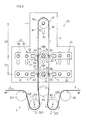
- FIG. 1 is a schematic configuration diagram showing a welding system when an M-size wearing article is manufactured according to an embodiment of the present invention.
- FIG. 2 is a schematic configuration diagram showing a welding system when manufacturing an L-sized wearing article.
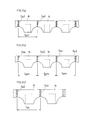
- FIGS. 3A to 3C are schematic front views showing examples of worn articles before being cut into individual products. 4 (a) to 4 (d) are conceptual diagrams showing the welding process of the present invention.
- the apparatus further includes first size adjusting means that can change a first distance between the first anvil roll and the second anvil roll.
- the first distance means the distance between the axes of both anvil rolls.
- the first distance between the two anvil rolls changeable, for example, it is possible to cope with size changes such as S size, M size, and L size of the worn article.
- the apparatus further comprises second size adjusting means for changing a second distance between the second anvil roll and the reversing roll.
- the second distance means the distance between the axes of the second anvil roll and the reverse roll.
- the pair of anvils of the first anvil roll are provided symmetrically with respect to the axis of the first anvil roll
- the pair of anvils of the second anvil roll are provided symmetrically with respect to the axis of the second anvil roll.
- the welding system further includes a conveyance device that introduces the web from the first gap, receives the web from the second gap, and repeatedly performs high-speed conveyance and low-speed conveyance of the web at a predetermined cycle.
- a high speed conveyance of the web and a low speed conveyance of the web are performed with a length four times the welding pitch determined by the first distance between the first gap and the third gap as one cycle. It further includes a repeating process, Each ultrasonic welding process is executed during the low-speed conveyance.
- the web having a length four times the pitch to be welded is set as one conveyance cycle, the high-speed and low-speed conveyance of the web is repeated, so that the low-speed conveyance period can be shortened and the production speed can be improved. Since this system includes four ultrasonic horns, the web can be welded at the predetermined pitch even when the web having a length four times the pitch is set as one cycle of conveyance.
- the present system has a pair of first and second ultrasonic welding apparatuses 1 and 2 for welding the webs W while conveying a plurality of webs W stacked on each other.
- the first and second ultrasonic welding devices 1 and 2 are separated from each other in the flow direction of the web W.
- the first ultrasonic welding apparatus 1 includes a first anvil roll 10 ⁇ / b> A having a pair of anvils 11 and 12, and a first and a first that apply vibration energy to the web W in cooperation with the pair of anvils 11 and 12.
- the second ultrasonic welding apparatus 2 applies a vibration energy to the web W in cooperation with the second anvil roll 10B having another pair of anvils 13 and 14 and the pair of anvils 13 and 14. And fourth ultrasonic horns 23 and 24, and third and fourth sonic bodies 33 and 34 for generating ultrasonic vibrations in the ultrasonic horns 23 and 24, respectively.
- a mechanical vibration having a high frequency is applied to each of the horns 21 to 24, and the plurality of webs W passing between the ultrasonic horns 21 to 24 and the anvils 11 to 14 are frictionally heated to each other.
- Welded As the ultrasonic horns 21 to 24, for example, ultrasonic horns described in JP-T-10-513128 may be used.
- a seal pattern composed of a large number of convex portions may be formed on the surfaces of the horns 21 to 24, for example, a seal pattern composed of a large number of convex portions may be formed. Further, instead of forming a seal pattern on the surfaces of the horns 21 to 24, a seal pattern may be formed on the surfaces of the anvils 11 to 14.
- the web W is formed by stacking a plurality of thermoplastic webs that need to be welded to each other. Further, the welding regions Sa1, Sa2, Sa3, Sa4 of the web W sealed by the first and second ultrasonic welding apparatuses 1, 2 are, for example, disposable pants (FIG. 3 (a) to FIG. 3 (c)). It is an end of a product such as an example of a worn article.
- the pitch between the welding regions Sa1, Sa2, Sa3, and Sa4 is set to predetermined pitches Spm and Spl in advance for each of the M size and the L size.
- the pair of anvils 11 and 12 of the first anvil roll 10A in FIG. 1 are symmetrical with respect to the axis of the first anvil roll 10A (a line extending along the rotation center O of the first anvil roll 10A). Is provided. That is, the pair of anvils 11 and 12 are provided on the first anvil roll 10A at a pitch of 180 °.
- the first ultrasonic horn 21 and the second ultrasonic horn 22 are arranged symmetrically with respect to the rotation center (the axis) O of the first anvil roll 10A. That is, one of the pair of anvils 11 and 12 is opposed to the first ultrasonic horn 21, and at the same time, the other of the pair of anvils 11 and 12 is the second ultrasonic horn 22.
- the pair of ultrasonic horns 21 and 22 are arranged so that they can face each other.
- the pair of anvils 13 and 14 of the second anvil roll 10B are provided symmetrically with respect to the axis of the second anvil roll 10B (a line extending along the rotation center O of the second anvil roll 10B). ing. That is, the pair of anvils 13 and 14 are provided on the second anvil roll 10B at a pitch of 180 °.
- the third ultrasonic horn 23 and the fourth ultrasonic horn 24 are arranged symmetrically about the rotation center O of the second anvil roll 10B. That is, one of the pair of anvils 13 and 14 faces the third ultrasonic horn 23, and at the same time, the other of the pair of anvils 13 and 14 has the fourth ultrasonic horn 24.
- the pair of ultrasonic horns 23 and 24 are arranged so that they can face each other.
- Each of the pair of anvils 11 and 12 of the first anvil roll 10A is opposed to the first or second ultrasonic horns 21 and 22, and another of the second anvil roll 10B.
- the ultrasonic horns 21 to 24 simultaneously apply vibration energy to the web W. . Therefore, the web W is welded simultaneously at two locations for each of the anvil rolls 10A and 10B.
- each of the anvil rolls 10A and 10B simultaneously receives two forces in opposite directions toward the center O of the anvil rolls 10A and 10B from the ultrasonic horns 21 to 24 via the web W. .
- each anvil roll 10A, 10B receives the force from the opposite direction simultaneously, even if each ultrasonic horn 21-24 applies a big vibration energy to each anvil roll 10A, 10B, each anvil 11 -14 are less likely to be misaligned.
- each of the anvil rolls 10A and 10B may be provided with another pair or another plurality of pairs of anvils.
- 1st and 2nd anvil roll 10A, 10B is arrange
- This system includes a transfer device (transport means) 4.
- the transport device 4 includes a reverse roll R3 on the opposite side of the second anvil roll 10B from the first anvil roll 10A.
- the reversing roll R3 turns the web passing through the third gap ⁇ 3 toward the fourth gap ⁇ 4.
- the web W that has passed through the third gap ⁇ 3 from the first gap ⁇ 1 flows along the outer peripheral surface of the reversing roll R3, and then is conveyed to the second gap ⁇ 2 through the fourth gap ⁇ 4.
- the first and second ultrasonic welding apparatuses 1 and 2 and the transfer apparatus 4 are arranged so that the upstream side and the downstream side are generally symmetrical with each other.
- This system includes first to third size adjusting means 41 to 43.
- the first size adjusting means 41 can change the first distance (pitch) D1 between the first anvil roll 10A and the second anvil roll 10B.
- the second size adjusting means 42 can change the second distance (pitch) D2 between the second anvil roll 10B and the reverse roll R3.
- the third size adjusting means 43 can change the distance D ⁇ b> 1 between the first ultrasonic welding device 1 and the second ultrasonic welding device 2.
- the second distance D2 means the distance between the axis of the reversing roll R3 and the second anvil roll 10B
- the first distance D1 means the distance between the axes of the second anvil roll 10B and the first anvil roll 10A.
- the reversing roll R3, the first and second anvil rolls 10A, 10B are rotatably attached to the frame 5 via a fixture 50. Further, the reversing roll R3, the second anvil roll 10B, the third and fourth sonic bodies 33, 34 can change the mounting position in the flow direction of the web W through the long holes 51 formed in the frame 5. As shown in FIG. The elongated hole 51 extends along the flow direction of the web W.
- the reversing roll R3 is used by the first to third size adjusting means 41 to 43 shown in FIG.
- the second anvil roll 10B, the third sonic body 33, and the fourth sonic body 34 are supported at the first position P1 shown in FIG.
- the reversing roll R3 the first roll is made by the first to third size adjusting means 41 to 43 of FIG.
- the two anvil rolls 10B, the third sonic body 33 and the fourth sonic body 34 are supported at the second position P2 shown in FIG. That is, the first distance D1 and the second distance D2 shown in FIG. 2 are larger than the first distance D1 and the second distance D2 shown in FIG.
- the welding regions Sa1, Sa2, Sa3 and Sa4 of the wearing article N shown in FIGS. 4A to 4D are welded when the web W passes through the first gap ⁇ 1 to the fourth gap ⁇ 4 shown in FIG. .
- the welding is performed simultaneously in the first to fourth gaps ⁇ 1 to ⁇ 4. Therefore, the length of the portion of the web W from the first gap ⁇ 1 to the third gap ⁇ 3 (or the length of the portion from the second gap ⁇ 2 to the fourth gap ⁇ 4), that is, the first distance D1 is shown in FIG. )
- the reversing roll R3, the first and second ultrasonic welding apparatuses 1 and 2 in FIG. 1 are selectively supported at either the first position P1 or the second position P2, Wear articles of two or more sizes can be manufactured.
- the transmission 4 includes a first dancer roller R1, a second dancer roller R2, a drive roller R4, and a plurality of guide rollers G1, G2.
- the first dancer roller R1 in FIG. 1 receives the web W flowing in from the upstream and discharges the web W toward the first gap ⁇ 1.
- the second dancer roller R2 receives the web W discharged from the second gap ⁇ 2, and discharges the web W toward the downstream.
- the first and second dancer rollers R1 and R2 reciprocate (oscillate) as shown by phantom lines and solid lines.
- the first and second dancer rollers R1, R2 are rotated at the same rotational speed (circumferential speed) by a driving means (not shown).
- a first guide roller G1 is rotatably provided upstream of the first dancer roller R1.
- a second guide roller G2 is rotatably provided downstream of the second dancer roller R2.
- the first guide roller G1 guides the web W flowing toward the first dancer roller R1.
- the second guide roller G2 guides the web W flowing out from the second dancer roller R2.
- a driving roller R4 is disposed above the dancer rollers R1 and R2.
- the five rollers R1, R2, G1, G2, and R4 shown in FIGS. 1 and 2 rotate in synchronization with each other.
- the drive device for the five rollers is disclosed in WO2005 / 080065A1, and all the descriptions are incorporated here.
- the transmission 4 repeatedly performs high-speed conveyance and low-speed conveyance of the web W alternately between the two dancer rollers R1 and R2.
- the moving speed of the web W between the dancer rollers R1 and R2 is higher than the speed V of the web W flowing into the first dancer roller R1.
- the moving speed of the web W between the dancer rollers R1 and R2 is smaller than the speed V.
- the first dancer roller R1 approaches the first anvil roll 10A, and at the same time, the second dancer roller R2 moves away from the first anvil roll 10A.
- the web W is conveyed at a high speed between the dancer rollers R1 and R2.
- the low-speed conveyance as indicated by a dashed arrow D20, the first dancer roller R1 moves away from the first anvil roll 10A, and at the same time, the second dancer roller R2 approaches the first anvil roll 10A.
- the dancer rollers R1 and R2 move, the web W is conveyed at a low speed between the dancer rollers R1 and R2.
- the high-speed conveyance and the low-speed conveyance are repeatedly performed as the dancer rollers R1 and R2 repeatedly reciprocate (swing) in the directions of arrows D10 and D20.
- each ultrasonic horn 21 to 24 applies vibration energy to the web W
- the speed of the web W passing between each ultrasonic horn 21 to 24 and each anvil 11 to 14 is small. For this reason, the time during which the web W receives vibration energy becomes longer, and the energy received by the web W per unit area increases. Therefore, the reliability of welding increases.
- the web W shown in FIG. 1 flows from the first guide roller G1 along the outer peripheral surface of the first dancer roller R1 at a substantially constant speed V, and then passes through the first and third gaps ⁇ 1 and ⁇ 3.
- the direction is reversed, and further flows along the outer peripheral surface of the second dancer roller R2 through the fourth and second gaps ⁇ 4 and ⁇ 2, and then moves to the second guide roller G2 at a substantially constant speed V. Conveyed along.
- the first dancer roller R1 moves in the direction of the arrow D20 so that the length of the web W between the first dancer roller R1 and the first gap ⁇ 1 increases, and the second dancer roller R2 and the first dancer The second dancer roller R2 moves in the direction of arrow D20 so that the length of the web W between the two gaps ⁇ 2 is reduced. Thereby, the speed of the web W between the first dancer roller R1 and the second dancer roller R2 is smaller than the speed V of the web W flowing into the first dancer roller R1.
- the anvils 11 to 14 face the ultrasonic horns 21 to 24, and the sonic bodies 31 to 34 are operated.
- FIG. Adjacent to each other in the web W are simultaneously welded (sealed).
- the first dancer roller R1 moves in the direction of the arrow D10 so that the length of the web W between the first dancer roller R1 and the first gap ⁇ 1 in FIG. 1 decreases
- the second dancer roller R2 And the second dancer roller R2 moves in the direction of the arrow D10 so that the length of the web W between the second gap ⁇ 2 and the second gap ⁇ 2 increases.
- the speed of the web W between the first dancer roller R1 and the second dancer roller R2 becomes larger than the speed of the web W flowing into the first dancer roller R1.
- one welding region Sa3 may be overlapped and welded by two or more ultrasonic horns 21-24. That is, when the four anvils 11 to 14 in FIG. 1 are opposed to the four ultrasonic horns 21 to 24, the four ultrasonic horns 21 to 24 are in a predetermined portion of the web W (FIG. The vibration energy is applied to the welding region Sa3). Thereafter, when the four anvils 11 to 14 are opposed to the ultrasonic horns 21 to 24, the second to fourth ultrasonic horns 22 to 24 are caused to vibrate by the first ultrasonic horn 21. Vibration energy is applied to a predetermined portion (the welding region Sa3) of the web W to which is applied. As shown to Fig.3 (a), this welding area
- the welding region Sa3 (FIG. 3A) welded by the first ultrasonic horn 21 in the first gap ⁇ 1 in FIG. 1 is followed by any of the second to fourth gaps ⁇ 2 to ⁇ 4.
- the conveyance speed of the web W and the angular speed of the anvil roll 10 are controlled so as to be welded by the ultrasonic horns 22 to 24. In the case of such welding, vibration energy is applied twice to one place on the web, and the reliability of welding is increased.
- the welding regions Sa1 to Sa4 may be welded by only one of the ultrasonic horns 21 to 24.
- the welding regions Sa1 to Sa4 due to the first to fourth ultrasonic horns 21 appear repeatedly on the web W.
- an example will be described.
- the first distance D1 between the first gap ⁇ 1 and the third gap ⁇ 3 and the first distance D1 between the fourth gap ⁇ 4 and the second gap ⁇ 2 are respectively M in FIG.
- the size length Spm is set.
- the reverse roll R3 is attached to the frame 5 at the first position P1 so that the transport distance from the third gap ⁇ 3 to the fourth gap ⁇ 4 in FIG. 1 is five times as long as the first distance D1. In this arrangement, welding is performed as follows.
- the speed of the web W is changed so that the web W passes through the first gap ⁇ 1, the third gap ⁇ 3, the fourth gap ⁇ 4, and the second gap ⁇ 2.
- the first and third horns 21 and 23 in FIG. 4A ultrasonically weld the first part S1 and the second part S2 of the web W during low-speed conveyance, respectively.
- FIG. 4B after the web W is conveyed at a high speed by a length four times the first distance D1, the third portion S3 and the third portion S3 of the web W downstream from the second portion S2
- the first and third horns 21 and 23 are ultrasonically welded during the low-speed conveyance of the four parts S4.
- the ultrasonic welded portion of the web W is shown in black.
- the web W between the second part S2 and the third part S3 is transported.
- the second and fourth horns 22 and 24 are ultrasonically welded to the fifth part S5 and the sixth part S6, respectively, during low-speed conveyance.
- the third and first horns 23 and 21 are ultrasonically welded during the low-speed conveyance of the seventh part S7 and the eighth part S8 of the web W facing the sixth part S6 and the fifth part S5, respectively.
- the timing at which the sixth part S6 and the fifth part S5 are ultrasonically welded and the timing at which the seventh part S7 and the eighth part S8 are ultrasonically welded are the same.
- the web W is again conveyed at a high speed by a length four times the first distance D1, and the ninth part S9 and the tenth part S10 of the web W between the fourth part S4 and the seventh part S7 are moved to
- the second and fourth horns 22 and 24 are ultrasonically welded.
- the third and first horns 23 and 21 are ultrasonically welded during the low-speed conveyance of the eleventh part S11 and the twelfth part S12 of the web W facing the tenth part S10 and the ninth part S9.
- the portions of the web W facing each other through the anvil roll are also ultrasonically welded, but FIG. 4 (a) to FIG.
- illustration (black coating) of the welded portion of the web W facing each other is omitted for easy understanding of the process.
- the high-speed conveyance period is long, and the production speed can be further improved.
- the first distance D1 between the first gap ⁇ 1 and the third gap ⁇ 3 and the first distance D1 between the second gap ⁇ 2 and the fourth gap ⁇ 4 are shown.
- the first and second anvil rolls 10A and 10B and the first to fourth sonic bodies 31 to 34 are attached to the frame 5 so as to be equal to the product length Spm of 3 (b).
- the reversing roll R3 is attached to the frame 5 so that the length of the web W from the third gap ⁇ 3 to the fourth gap ⁇ 4 is an integral multiple (for example, five times) of the first distance D1.
- ultrasonic welding is intermittently performed, whereby the M-sized wearing article N shown in FIG. 3B is obtained.
- the 1st and 1st of FIG. 2 is made so that the said 1st distance D1 may become equal to the product length Spl of FIG.3 (c).
- the two anvil rolls 10A and 10B and the first to fourth sonic bodies 31 to 34 are attached to the frame 5.
- the reversing roll R3 is attached to the frame 5 so that the length of the web W from the third gap ⁇ 3 to the fourth gap ⁇ 4 is an integral multiple (for example, five times) of the first distance D1.
- the ultrasonic welding is intermittently performed to obtain the L-sized wearing article N shown in FIG.
- the reverse roller and the transmission device are not necessarily provided. Further, the reverse roller position may be fixedly provided. Moreover, in the method of changing the size of the wearing article, the reversing roll, the second anvil roll, the third sonic main body, and the fourth sonic main body may be moved along the long holes by power such as a motor or a cylinder. Furthermore, a guide member such as a linear guide may be used instead of the long hole.
- the reversing roller, the first anvil roll, the second anvil roll, and each sonic main body may have means capable of finely adjusting each position at the first position and the second position. Further, the dancer roller may swing left and right instead of up and down. Accordingly, such changes and modifications are to be construed as within the scope of the present invention as defined by the claims.
- the welding system of the present invention can be used for the production of disposable wearing articles such as disposable pants, diapers and sanitary products.
Landscapes
- Engineering & Computer Science (AREA)
- Mechanical Engineering (AREA)
- Health & Medical Sciences (AREA)
- Life Sciences & Earth Sciences (AREA)
- General Health & Medical Sciences (AREA)
- Biomedical Technology (AREA)
- Heart & Thoracic Surgery (AREA)
- Vascular Medicine (AREA)
- Manufacturing & Machinery (AREA)
- Animal Behavior & Ethology (AREA)
- Epidemiology (AREA)
- Public Health (AREA)
- Veterinary Medicine (AREA)
- Absorbent Articles And Supports Therefor (AREA)
- Lining Or Joining Of Plastics Or The Like (AREA)
- Pressure Welding/Diffusion-Bonding (AREA)
- Treatment Of Fiber Materials (AREA)
Abstract
Description
この先行技術は、連続ウエブを反転ロールにて反転させるとともに、反転ロールの上流および下流のウエブの双方に接触可能な一対のアンビルを有するアンビルロールが設けられている。各アンビルに対応した超音波ホーンにより反転ロールの前後でウエブにシール加工が行われる。
しかし、前記先行技術において前記アンビルロールを複数個設けることについては何ら開示も示唆もなされていない。
前記一対のアンビルと協働して前記ウエブに振動エネルギーを印加する第1および第2の超音波ホーンと、
別の一対のアンビルを有する第2アンビルロールと、
前記第2アンビルロールの一対のアンビルと協働して前記ウエブに振動エネルギーを印加する第3および第4の超音波ホーンとを備え、
前記第1アンビルロールの一対のアンビルのうちのいずれか一方が前記第1のホーンに対向すると、同時に、前記第1アンビルロールの一対のアンビルのうちの他方が前記第2のホーンに対向することが可能なように、前記第1および第2の超音波ホーンは配置されており、
前記第2アンビルロールの一対のアンビルのうちのいずれか一方が前記第3のホーンに対向すると、同時に、前記第2アンビルロールの一対のアンビルのうちの他方が前記第4のホーンに対向することが可能なように、前記第3および第4の超音波ホーンは配置されており、
前記第1アンビルロールと前記第1のホーンとの間の第1間隙、前記第2アンビルロールと前記第3のホーンとの間の第3間隙、前記第2アンビルロールと前記第2のホーンとの間の第4間隙および前記第1アンビルロールと前記第2のホーンとの間の第2間隙の順に前記ウエブが搬送されるように、前記第1および第2アンビルロールが配置されている。
前記第1および第3のホーンで前記ウエブの第1部および第2部を、それぞれ、超音波溶着する工程と、
前記第2部よりも下流の前記ウエブの第3部および第4部を、それぞれ、前記第1および第3ホーンで超音波溶着する工程と、
前記第2部と前記第3部との間の前記ウエブの第5部および第6部を、それぞれ、前記第2および第4ホーンで超音波溶着する工程とを備える。
つまり、第1および第3のホーンが第1部および第2部を溶着してから第3部および第4部を溶着するまでの間に、2箇所の溶着すべき部位(下流において第2および第4ホーンで溶着される第5部および第6部)を飛ばしてウエブが搬送され得る。したがって、溶着の高速化が可能である。
前記第2アンビルロールと前記反転ロールとの間の第2距離を変更可能とする第2のサイズ調整手段とを更に備える。なお、第2距離は第2アンビルロールおよび反転ロールの各軸線間の距離を意味する。
前記第2アンビルロールの一対のアンビルは前記第2アンビルロールの軸線を中心に互いに対称に設けられている。
アンビルロールが互いに反対の方向からの力を同時に受け、超音波エネルギーの衝撃によるアンビルロールの負荷が小さくなると共に、超音波ホーンが振動エネルギーをアンビルロールに印加しても、アンビルが位置ズレしにくくなる。したがって、溶着の位置精度が向上する。
前記溶着方法は、前記第1間隙と第3間隙との間の第1距離により定まる溶着のピッチの4倍の長さを1周期として、前記ウエブの高速搬送と、前記ウエブの低速搬送とを繰り返す工程を更に備え、
前記低速搬送時に前記各超音波溶着の工程を実行する。
なお、本システムは超音波ホーンを4個備えているため、前記ピッチの4倍の長さのウエブを搬送の1周期としても、ウエブを所定の前記ピッチで溶着し得る。
以下の説明では、まず、本発明の溶着システムの要部について説明し、その後に、前記溶着システムに設けられた変速装置について説明する。
前記超音波ホーン21~24としては、たとえば、特表平10-513128号に記載の超音波ホーンが用いられてもよい。周知のように、ホーン21~24の表面には、たとえば、多数の凸部からなるシールパターンが形成されていてもよい。
また、ホーン21~24の表面にシールパターンを形成する代わりに、アンビル11~14の表面にシールパターンが形成されていてもよい。
各溶着領域Sa1,Sa2,Sa3,Sa4の間のピッチはMサイズ、Lサイズごとに予め所定のピッチSpm,Splに設定されている。
すなわち、前記一対のアンビル11,12のうちのいずれか一方が前記第1の超音波ホーン21に対向し、同時に、前記一対のアンビル11,12のうちの他方が前記第2の超音波ホーン22に対向することが可能なように、前記一対の超音波ホーン21,22は配置されている。
すなわち、前記一対のアンビル13,14のうちのいずれか一方が前記第3の超音波ホーン23に対向し、同時に、前記一対のアンビル13,14のうちの他方が前記第4の超音波ホーン24に対向することが可能なように、前記一対の超音波ホーン23,24は配置されている。
この際、前記各アンビルロール10A,10Bは、前記アンビルロール10A,10Bの中心Oに向かう互いに反対の方向の2つの力を、前記ウエブWを介して、前記超音波ホーン21~24から同時に受ける。
このように、各アンビルロール10A,10Bが同時に互いに反対の方向からの力を受けるので、各超音波ホーン21~24が大きな振動エネルギーを各アンビルロール10A,10Bに印加しても、各アンビル11~14が位置ズレしにくくなる。
前記第1間隙Δ1から前記第3間隙Δ3を通過したウエブWは、前記反転ロールR3の外周面に沿って流れた後、前記第4間隙Δ4を通って前記第2間隙Δ2に搬送される。
なお、本システムにおいて、前記第1および第2超音波溶着装置1,2および搬送装置4等は、上流側と下流側とが概ね互いに面対称になるように配置されている。
第1のサイズ調整手段41は前記第1アンビルロール10Aと前記第2アンビルロール10Bとの間の第1距離(ピッチ)D1を変更可能とする。
第2のサイズ調整手段42は第2アンビルロール10Bと反転ロールR3との間の第2距離(ピッチ)D2を変更可能とする。
第3のサイズ調整手段43は第1超音波溶着装置1と第2超音波溶着装置2との間の距離D1を変更可能とする。
なお、第2距離D2は反転ロールR3および第2アンビルロール10Bの軸心間の距離を意味し、第1距離D1は第2アンビルロール10Bおよび第1アンビルロール10Aの軸心間の距離を意味する。
なお、前記長孔51はウエブWの流れ方向に沿って延びている。
一方、図3(c)の第2のサイズ(たとえばLサイズ)の着用物品を製造する場合には、図2の前記第1~第3サイズ調整手段41~43により、前記反転ロールR3、第2アンビルロール10B、第3ソニック本体33および第4ソニック本体34が図2で示す前記第2位置P2に支持される。
すなわち、図1に示す前記第1距離D1および第2距離D2に比べ、図2に示す前記第1距離D1および第2距離D2はそれぞれ大きい。
一方、前記溶着は前記第1~第4間隙Δ1~Δ4において同時になされる。したがって、ウエブWにおける第1間隙Δ1から第3間隙Δ3までの部分の長さ(または第2間隙Δ2から第4間隙Δ4までの部分の長さ)、つまり第1距離D1は、図3(a)~図3(c)の着用物品NのピッチSpm又はSplの整数倍に設定される必要がある。
そのため、前述のように、図1の反転ロールR3、第1および第2の超音波溶着装置1,2が第1位置P1または第2位置P2のいずれかにおいて選択的に支持されることにより、2種以上のサイズの着用物品を製造することができる。
前記第1ガイドローラG1は、前記第1ダンサーローラR1に向って流れるウエブWを案内する。一方、前記第2ガイドローラG2は前記第2ダンサーローラR2から流れ出るウエブWを案内する。
前記両ダンサーローラR1,R2の間の上方の位置には、駆動ローラR4が配置されている。図1および図2に示す前記5つのローラR1,R2,G1,G2,R4は互いに同期して回転する。
なお、前記5つのローラの駆動装置はWO2005/080065A1に開示されており、ここに、その記述の全てが組み込まれる。
一方、前記低速搬送において、前記ダンサーローラR1,R2間の前記ウエブWの移動速度は、前記速度Vよりも小さい。
一方、前記低速搬送においては、破線の矢印D20で示すように、前記第1ダンサーローラR1が前記第1アンビルロール10Aから遠ざかり、同時に、前記第2ダンサーローラR2が前記第1アンビルロール10Aに近づくように前記両ダンサーローラR1,R2が移動することで、前記両ダンサーローラR1,R2間においてウエブWが低速で搬送される。
一方、前記各アンビル11~14が、各超音波ホーン21~24に対向していない状態である場合に、第1ダンサーローラR1と前記第2ダンサーローラR2との間の前記ウエブWの速度Vが、前記第1ダンサーローラR1に流入する前記ウエブWの速度Vよりも大きくなるように前記制御装置(図示せず)により制御される。
図1の前記ウエブWは、概ね一定の速度Vで第1ガイドローラG1から前記第1ダンサーローラR1の外周面に沿って流れた後、前記第1および第3間隙Δ1,Δ3を通り、反転ロールR3において方向が反転され、更に前記第4および第2間隙Δ4,Δ2を通り、前記第2ダンサーローラR2の外周面に沿って流れ、その後、概ね一定の速度Vで第2ガイドローラG2に沿って搬送される。
これにより、前記第1ダンサーローラR1と前記第2ダンサーローラR2との間の前記ウエブWの速度が、前記第1ダンサーローラR1に流入する前記ウエブWの速度Vよりも小さくなる。
これにより、前記第1ダンサーローラR1と前記第2ダンサーローラR2との間の前記ウエブWの速度が、前記第1ダンサーローラR1に流入する前記ウエブWの速度よりも大きくなる。
すなわち、図1の前記4つの各アンビル11~14が前記4つの超音波ホーン21~24に対向する際に、前記4つの超音波ホーン21~24がウエブWの所定の部位(図3(a)の溶着領域Sa3)に振動エネルギーを印加する。その後、前記4つのアンビル11~14が前記各超音波ホーン21~24に対向する際に、前記第2~第4の超音波ホーン22~24が、前記第1の超音波ホーン21により振動エネルギーが印加されたウエブWの所定の部位(前記溶着領域Sa3)に重ねて振動エネルギーを印加する。
図3(a)に示すように、この溶着領域Sa3は着用物品などの製品の端部となる。
かかる溶着の場合、ウエブの1箇所に2回にわたり振動エネルギーが印加され、溶着の信頼性が高くなる。
この場合、図3(b)のように、ウエブWには、第1~第4の超音波ホーン21による溶着領域Sa1~Sa4が繰り返し現れる。
以下、その一例について説明する。
一方、図1の第3間隙Δ3~第4間隙Δ4までの搬送距離は前記第1距離D1の5倍の長さとなるように反転ロールR3が第1の位置P1においてフレーム5に取り付けられる。この配置において以下のように溶着が行われる。
その後、図4(b)のように、第1距離D1の4倍の長さ分だけウエブWを高速搬送した後に、前記第2部S2よりも下流の前記ウエブWの第3部S3および第4部S4を、それぞれ、低速搬送中に前記第1および第3ホーン21,23が超音波溶着する。
なお、図4(a)~図4(d)において、超音波溶着されたウエブWの部位を黒塗りで示している。
この際、前記第6部S6および第5部S5にそれぞれ対面するウエブWの第7部S7および第8部S8を、前記低速搬送中に、第3および第1ホーン23,21が超音波溶着する。
すなわち、前記第6部S6および第5部S5が超音波溶着されるタイミングと前記第7部S7および第8部S8が超音波溶着されるタイミングとは同じである。
この際、前記第10部S10および第9部S9にそれぞれ対面するウエブWの第11部S11および第12部S12を、前記低速搬送中に、第3および第1ホーン23,21が超音波溶着する。
なお、第1部S1~第4部S4が超音波溶着される際も、同様に、それぞれアンビルロールを介して対面するウエブWの部位が超音波溶着されるが、図4(a)~図4(b)では、工程の説明を分り易くするため、同対面するウエブWの溶着部位の図示(黒塗り)は省略している。
一方、第3間隙Δ3~第4間隙Δ4までのウエブWの長さが前記第1距離D1の整数倍(例えば5倍)となるように、反転ロールR3をフレーム5に取り付ける。この状態で、前述のように、間欠的に超音波溶着を行うことで、図3(b)のMサイズの着用物品Nが得られる。
一方、第3間隙Δ3~第4間隙Δ4までのウエブWの長さが前記第1距離D1の整数倍(例えば5倍)となるように、反転ロールR3をフレーム5に取り付ける。この状態で、前述のように、間欠的に超音波溶着を行うことで、図3(c)のLサイズの着用物品Nが得られる。
たとえば、反転ローラや変速装置は必ずしも設けられる必要はない。
また、反転ローラ位置が固定的に設けられてもよい。
また、着用物品のサイズを変更する方法において、反転ロール、第2アンビルロール、第3ソニック本体および第4ソニック本体は長孔に沿ってモータやシリンダ等の動力で移動されてもよい。更に、前記長孔に代えてリニアガイドのような案内部材が用いられてもよい。
また、前記反転ローラ、第1アンビルロール、第2アンビルロールおよび各ソニック本体は第1位置および第2位置において各々の位置を微調整することができる手段を有していてもよい。
また、ダンサーローラは上下ではなく左右に揺動してもよい。
したがって、そのような変更および修正は、請求の範囲から定まる本発明の範囲内のものと解釈される。
10A:第1アンビルロール 10B:第2アンビルロール
11~14:第1~第4アンビル
21~24:第1~第4の超音波ホーン 31~34:第1~第4ソニック本体
4:搬送装置 41,42:第1~第2のサイズ調整手段
5:フレーム 50:取付具 51:長孔
N:着用物品 P1:第1の位置 P2:第2の位置
R1:第1ダンサーローラ R2:第2ダンサーローラ R3:反転ローラ R4:駆動ローラ
S1~S10:第1部~第10部 Sa1~Sa4:溶着領域
Δ1~Δ4:第1間隙~第4間隙
Claims (6)
- 複数枚のウエブを搬送しながら、前記ウエブ同士を溶着させる超音波溶着装置を有するウエブの溶着システムであって、前記超音波溶着装置は、
一対のアンビルを有する第1アンビルロールと、
前記一対のアンビルと協働して前記ウエブに振動エネルギーを印加する第1および第2の超音波ホーンと、
別の一対のアンビルを有する第2アンビルロールと、
前記第2アンビルロールの一対のアンビルと協働して前記ウエブに振動エネルギーを印加する第3および第4の超音波ホーンとを備え、
前記第1アンビルロールの一対のアンビルのうちのいずれか一方が前記第1のホーンに対向すると、同時に、前記第1アンビルロールの一対のアンビルのうちの他方が前記第2のホーンに対向することが可能なように、前記第1および第2の超音波ホーンは配置されており、
前記第2アンビルロールの一対のアンビルのうちのいずれか一方が前記第3のホーンに対向すると、同時に、前記第2アンビルロールの一対のアンビルのうちの他方が前記第4のホーンに対向することが可能なように、前記第3および第4の超音波ホーンは配置されており、
前記第1アンビルロールと前記第1のホーンとの間の第1間隙、前記第2アンビルロールと前記第3のホーンとの間の第3間隙、前記第2アンビルロールと前記第2のホーンとの間の第4間隙および前記第1アンビルロールと前記第2のホーンとの間の第2間隙の順に前記ウエブが搬送されるように、前記第1および第2アンビルロールが配置されている。 - 請求項1のシステムにおいて、前記第1アンビルロールと前記第2アンビルロールとの間の第1距離を変更可能とする第1のサイズ調整手段を更に備える。
- 請求項2のシステムにおいて、前記第2アンビルロールの第1アンビルロールとは反対側に、前記第3間隙を通ったウエブを前記第4間隙に向かって転向させる反転ロールと、
前記第2アンビルロールと前記反転ロールとの間の第2距離を変更可能とする第2のサイズ調整手段とを更に備える。 - 請求項3のシステムにおいて、前記第1アンビルロールの一対のアンビルは前記第1アンビルロールの軸線を中心に互いに対称に設けられ、
前記第2アンビルロールの一対のアンビルは前記第2アンビルロールの軸線を中心に互いに対称に設けられている。 - 請求項1のシステムを用いたウエブの溶着方法であって、
前記ウエブが前記第1間隙、第3間隙、第4間隙および第2間隙の順に通るように前記ウエブを搬送する工程と、
前記第1および第3のホーンで前記ウエブの第1部および第2部を、それぞれ、超音波溶着する工程と、
前記第2部よりも下流の前記ウエブの第3部および第4部を、それぞれ、前記第1および第3ホーンで超音波溶着する工程と、
前記第2部と前記第3部との間の前記ウエブの第5部および第6部を、それぞれ、前記第2および第4ホーンで超音波溶着する工程とを備える。 - 請求項5のウエブの溶着方法において、
前記溶着システムは前記ウエブを前記第1間隙から導入し、前記第2間隙からの前記ウエブを受け取ると共に、所定の周期でウエブの高速搬送と低速搬送とを繰り返し行う搬送装置を更に備え、
前記溶着方法は、前記第1間隙と第3間隙との間の第1距離により定まる溶着のピッチの4倍の長さを1周期として、前記ウエブの高速搬送と、前記ウエブの低速搬送とを繰り返す工程を更に備え、
前記低速搬送時に前記各超音波溶着の工程を実行する。
Priority Applications (4)
| Application Number | Priority Date | Filing Date | Title |
|---|---|---|---|
| CN201380058831.8A CN104780877B (zh) | 2012-11-13 | 2013-11-05 | 片状物的熔接系统以及熔接方法 |
| US14/439,633 US9186845B2 (en) | 2012-11-13 | 2013-11-05 | Web welding system and welding method |
| JP2014546942A JP6242805B2 (ja) | 2012-11-13 | 2013-11-05 | ウエブの溶着システムおよび溶着方法 |
| BR112015009494-5A BR112015009494B1 (pt) | 2012-11-13 | 2013-11-05 | Sistema de soldagem de trama e método de soldagem |
Applications Claiming Priority (2)
| Application Number | Priority Date | Filing Date | Title |
|---|---|---|---|
| JP2012-249097 | 2012-11-13 | ||
| JP2012249097A JP2014097097A (ja) | 2012-11-13 | 2012-11-13 | ウエブの溶着システムおよび溶着方法 |
Publications (1)
| Publication Number | Publication Date |
|---|---|
| WO2014077152A1 true WO2014077152A1 (ja) | 2014-05-22 |
Family
ID=50731067
Family Applications (1)
| Application Number | Title | Priority Date | Filing Date |
|---|---|---|---|
| PCT/JP2013/079842 Ceased WO2014077152A1 (ja) | 2012-11-13 | 2013-11-05 | ウエブの溶着システムおよび溶着方法 |
Country Status (6)
| Country | Link |
|---|---|
| US (1) | US9186845B2 (ja) |
| JP (2) | JP2014097097A (ja) |
| CN (1) | CN104780877B (ja) |
| BR (1) | BR112015009494B1 (ja) |
| MY (1) | MY170157A (ja) |
| WO (1) | WO2014077152A1 (ja) |
Cited By (4)
| Publication number | Priority date | Publication date | Assignee | Title |
|---|---|---|---|---|
| CN104400993A (zh) * | 2014-10-28 | 2015-03-11 | 杭州珂瑞特机械制造有限公司 | 全伺服柔和性婴儿拉拉裤生产线 |
| CN104400995A (zh) * | 2014-10-28 | 2015-03-11 | 杭州珂瑞特机械制造有限公司 | 婴儿拉拉裤腰围超声波浮动焊接系统及浮动焊接方法 |
| WO2020241245A1 (ja) | 2019-05-24 | 2020-12-03 | 株式会社瑞光 | ウェブの溶着システムおよび溶着方法 |
| CN114226945A (zh) * | 2021-12-27 | 2022-03-25 | 上海骄成超声波技术股份有限公司 | 超声波焊接装置及连续焊接方法 |
Families Citing this family (13)
| Publication number | Priority date | Publication date | Assignee | Title |
|---|---|---|---|---|
| WO2014200104A1 (ja) * | 2013-06-14 | 2014-12-18 | 株式会社瑞光 | 超音波溶着装置及びこれを用いた使い捨ておむつの製造方法 |
| JP6343280B2 (ja) * | 2013-06-14 | 2018-06-13 | 株式会社瑞光 | アンビルローラ及びこれを備えた超音波溶着装置 |
| CN105283300B (zh) * | 2013-06-14 | 2017-12-12 | 株式会社瑞光 | 超声波焊头、具备该超声波焊头的熔接机以及利用了超声波焊头的一次性尿布的制造方法 |
| US9775749B2 (en) * | 2015-02-04 | 2017-10-03 | The Procter & Gamble Company | Apparatuses and methods for transferring and bonding substrates |
| US10561539B2 (en) | 2016-09-15 | 2020-02-18 | Curt G. Joa, Inc. | Dual bonder |
| EP3478480B1 (en) | 2016-09-15 | 2021-09-01 | Curt G. Joa, Inc. | Dual bonder |
| CN107662345A (zh) * | 2016-12-17 | 2018-02-06 | 黄山富田精工制造有限公司 | 片状物的熔接系统及其方法 |
| CN106806066B (zh) * | 2017-04-02 | 2020-02-21 | 黄山富田精工制造有限公司 | 颗粒性吸收材料的供给方法 |
| CN107028702B (zh) * | 2017-04-02 | 2020-03-17 | 黄山富田精工制造有限公司 | 吸收性物品的制造装置 |
| US20190018159A1 (en) * | 2017-07-13 | 2019-01-17 | Axxis Geo Solutions AS | Deployment and Retrieval Method and Apparatus for Seismic Nodal Recording Systems |
| US10710293B2 (en) * | 2018-10-23 | 2020-07-14 | Pavel Savenok | Composite article assembly system and method |
| EP3870426B1 (en) * | 2018-10-26 | 2025-07-16 | Curt G. Joa, Inc. | Dual bonder |
| US11192310B2 (en) | 2019-07-11 | 2021-12-07 | Curt G. Joa, Inc. | Method and apparatus for improved ultrasonic bonding |
Citations (2)
| Publication number | Priority date | Publication date | Assignee | Title |
|---|---|---|---|---|
| JP2001506945A (ja) * | 1996-12-20 | 2001-05-29 | キンバリー クラーク ワールドワイド インコーポレイテッド | 全幅超音波結合方法およびその装置 |
| WO2005080065A1 (ja) * | 2004-02-25 | 2005-09-01 | Zuiko Corporation | ウエブの溶着システム |
Family Cites Families (10)
| Publication number | Priority date | Publication date | Assignee | Title |
|---|---|---|---|---|
| US4414045A (en) * | 1982-02-22 | 1983-11-08 | Burlington Industries, Inc. | High speed ultrasonic bonding |
| US4713132A (en) * | 1986-05-08 | 1987-12-15 | Kimberly-Clark Corporation | Apparatus and method for ultrasonic bonding of a moving web |
| US4758293A (en) * | 1986-06-25 | 1988-07-19 | Kimberly-Clark Corporation | Ultrasonic bonding apparatus and method |
| US5660679A (en) * | 1995-01-31 | 1997-08-26 | Kimberly-Clark Worldwide, Inc. | Rotary sealing system |
| DE19712498C2 (de) * | 1997-03-25 | 1999-01-14 | Windmoeller & Hoelscher | Vorrichtung zum Verschweißen flach aufeinanderliegender Werkstücke im Ultraschallschweißverfahren |
| US6454890B1 (en) * | 2000-11-30 | 2002-09-24 | Kimberly-Clark Worldwide, Inc. | Method and apparatus for up to full width ultrasonic bonding |
| ITBO20040241A1 (it) * | 2004-04-22 | 2004-07-22 | Azionaria Costruzioni Acma Spa | Gruppo ruotante per la saldatura ed ultrasuoni di nastri tubolari continui |
| CN100475498C (zh) * | 2004-04-30 | 2009-04-08 | 株式会社瑞光 | 熔接装置 |
| JP4592690B2 (ja) * | 2004-04-30 | 2010-12-01 | 株式会社瑞光 | 溶着装置 |
| JP4966716B2 (ja) * | 2007-04-06 | 2012-07-04 | ユニ・チャーム株式会社 | 加工装置 |
-
2012
- 2012-11-13 JP JP2012249097A patent/JP2014097097A/ja active Pending
-
2013
- 2013-11-05 MY MYPI2015701386A patent/MY170157A/en unknown
- 2013-11-05 WO PCT/JP2013/079842 patent/WO2014077152A1/ja not_active Ceased
- 2013-11-05 JP JP2014546942A patent/JP6242805B2/ja not_active Expired - Fee Related
- 2013-11-05 US US14/439,633 patent/US9186845B2/en active Active
- 2013-11-05 BR BR112015009494-5A patent/BR112015009494B1/pt not_active IP Right Cessation
- 2013-11-05 CN CN201380058831.8A patent/CN104780877B/zh active Active
Patent Citations (2)
| Publication number | Priority date | Publication date | Assignee | Title |
|---|---|---|---|---|
| JP2001506945A (ja) * | 1996-12-20 | 2001-05-29 | キンバリー クラーク ワールドワイド インコーポレイテッド | 全幅超音波結合方法およびその装置 |
| WO2005080065A1 (ja) * | 2004-02-25 | 2005-09-01 | Zuiko Corporation | ウエブの溶着システム |
Cited By (5)
| Publication number | Priority date | Publication date | Assignee | Title |
|---|---|---|---|---|
| CN104400993A (zh) * | 2014-10-28 | 2015-03-11 | 杭州珂瑞特机械制造有限公司 | 全伺服柔和性婴儿拉拉裤生产线 |
| CN104400995A (zh) * | 2014-10-28 | 2015-03-11 | 杭州珂瑞特机械制造有限公司 | 婴儿拉拉裤腰围超声波浮动焊接系统及浮动焊接方法 |
| WO2020241245A1 (ja) | 2019-05-24 | 2020-12-03 | 株式会社瑞光 | ウェブの溶着システムおよび溶着方法 |
| US11772332B2 (en) | 2019-05-24 | 2023-10-03 | Zuiko Corporation | Web welding system and welding method |
| CN114226945A (zh) * | 2021-12-27 | 2022-03-25 | 上海骄成超声波技术股份有限公司 | 超声波焊接装置及连续焊接方法 |
Also Published As
| Publication number | Publication date |
|---|---|
| US9186845B2 (en) | 2015-11-17 |
| JP2014097097A (ja) | 2014-05-29 |
| JP6242805B2 (ja) | 2017-12-06 |
| US20150298390A1 (en) | 2015-10-22 |
| MY170157A (en) | 2019-07-09 |
| JPWO2014077152A1 (ja) | 2017-01-05 |
| BR112015009494A2 (pt) | 2017-07-04 |
| BR112015009494B1 (pt) | 2021-12-28 |
| CN104780877A (zh) | 2015-07-15 |
| CN104780877B (zh) | 2017-07-18 |
Similar Documents
| Publication | Publication Date | Title |
|---|---|---|
| JP6242805B2 (ja) | ウエブの溶着システムおよび溶着方法 | |
| CN100526055C (zh) | 带材熔接系统 | |
| JP6871648B2 (ja) | デュアルボンダー | |
| EP1302424B1 (en) | Web velocity modulator | |
| US6349867B1 (en) | Apparatus for transporting continuous elongate material webs | |
| US20180042779A1 (en) | Methods and apparatuses for assembling elastic laminates with different bond densities for absorbent articles | |
| CN110091510B (zh) | 一种超声波焊接装置 | |
| US9144624B2 (en) | Method for providing a localized dwell in an advancing web | |
| EP3845382B1 (en) | Method of forming a composite web utilizing a rotary bonding system with an anvil pattern | |
| EP3870426B1 (en) | Dual bonder | |
| CN108430773A (zh) | 超声密封器 | |
| CN210100736U (zh) | 一种超声波焊接装置 | |
| CN210100737U (zh) | 一种超声波焊接装置 | |
| JP7573522B2 (ja) | ウェブの溶着システムおよび溶着方法 | |
| JP5155809B2 (ja) | 複合シートの製造方法 | |
| CN210100735U (zh) | 一种超声波焊接装置 | |
| TH114931A (th) | วิธีการผลิตและอุปกรณ์การผลิตของแผ่นผสมของผลิตภัณฑ์ซึมซับ |
Legal Events
| Date | Code | Title | Description |
|---|---|---|---|
| 121 | Ep: the epo has been informed by wipo that ep was designated in this application |
Ref document number: 13854461 Country of ref document: EP Kind code of ref document: A1 |
|
| ENP | Entry into the national phase |
Ref document number: 2014546942 Country of ref document: JP Kind code of ref document: A |
|
| WWE | Wipo information: entry into national phase |
Ref document number: 14439633 Country of ref document: US |
|
| REG | Reference to national code |
Ref country code: BR Ref legal event code: B01A Ref document number: 112015009494 Country of ref document: BR |
|
| NENP | Non-entry into the national phase |
Ref country code: DE |
|
| WWE | Wipo information: entry into national phase |
Ref document number: IDP00201503361 Country of ref document: ID |
|
| 122 | Ep: pct application non-entry in european phase |
Ref document number: 13854461 Country of ref document: EP Kind code of ref document: A1 |
|
| ENP | Entry into the national phase |
Ref document number: 112015009494 Country of ref document: BR Kind code of ref document: A2 Effective date: 20150428 |