WO2014073475A1 - Battery controller, power storage device, power storage method, and program - Google Patents
Battery controller, power storage device, power storage method, and program Download PDFInfo
- Publication number
- WO2014073475A1 WO2014073475A1 PCT/JP2013/079689 JP2013079689W WO2014073475A1 WO 2014073475 A1 WO2014073475 A1 WO 2014073475A1 JP 2013079689 W JP2013079689 W JP 2013079689W WO 2014073475 A1 WO2014073475 A1 WO 2014073475A1
- Authority
- WO
- WIPO (PCT)
- Prior art keywords
- secondary battery
- battery
- charging current
- current rate
- charged
- Prior art date
Links
Images


Classifications
-
- H—ELECTRICITY
- H02—GENERATION; CONVERSION OR DISTRIBUTION OF ELECTRIC POWER
- H02J—CIRCUIT ARRANGEMENTS OR SYSTEMS FOR SUPPLYING OR DISTRIBUTING ELECTRIC POWER; SYSTEMS FOR STORING ELECTRIC ENERGY
- H02J7/00—Circuit arrangements for charging or depolarising batteries or for supplying loads from batteries
- H02J7/007—Regulation of charging or discharging current or voltage
-
- H—ELECTRICITY
- H01—ELECTRIC ELEMENTS
- H01M—PROCESSES OR MEANS, e.g. BATTERIES, FOR THE DIRECT CONVERSION OF CHEMICAL ENERGY INTO ELECTRICAL ENERGY
- H01M10/00—Secondary cells; Manufacture thereof
- H01M10/42—Methods or arrangements for servicing or maintenance of secondary cells or secondary half-cells
- H01M10/44—Methods for charging or discharging
- H01M10/441—Methods for charging or discharging for several batteries or cells simultaneously or sequentially
-
- H—ELECTRICITY
- H01—ELECTRIC ELEMENTS
- H01M—PROCESSES OR MEANS, e.g. BATTERIES, FOR THE DIRECT CONVERSION OF CHEMICAL ENERGY INTO ELECTRICAL ENERGY
- H01M10/00—Secondary cells; Manufacture thereof
- H01M10/42—Methods or arrangements for servicing or maintenance of secondary cells or secondary half-cells
- H01M10/48—Accumulators combined with arrangements for measuring, testing or indicating the condition of cells, e.g. the level or density of the electrolyte
- H01M10/482—Accumulators combined with arrangements for measuring, testing or indicating the condition of cells, e.g. the level or density of the electrolyte for several batteries or cells simultaneously or sequentially
-
- H—ELECTRICITY
- H02—GENERATION; CONVERSION OR DISTRIBUTION OF ELECTRIC POWER
- H02J—CIRCUIT ARRANGEMENTS OR SYSTEMS FOR SUPPLYING OR DISTRIBUTING ELECTRIC POWER; SYSTEMS FOR STORING ELECTRIC ENERGY
- H02J7/00—Circuit arrangements for charging or depolarising batteries or for supplying loads from batteries
- H02J7/0013—Circuit arrangements for charging or depolarising batteries or for supplying loads from batteries acting upon several batteries simultaneously or sequentially
-
- H—ELECTRICITY
- H02—GENERATION; CONVERSION OR DISTRIBUTION OF ELECTRIC POWER
- H02J—CIRCUIT ARRANGEMENTS OR SYSTEMS FOR SUPPLYING OR DISTRIBUTING ELECTRIC POWER; SYSTEMS FOR STORING ELECTRIC ENERGY
- H02J7/00—Circuit arrangements for charging or depolarising batteries or for supplying loads from batteries
- H02J7/0047—Circuit arrangements for charging or depolarising batteries or for supplying loads from batteries with monitoring or indicating devices or circuits
-
- H—ELECTRICITY
- H02—GENERATION; CONVERSION OR DISTRIBUTION OF ELECTRIC POWER
- H02J—CIRCUIT ARRANGEMENTS OR SYSTEMS FOR SUPPLYING OR DISTRIBUTING ELECTRIC POWER; SYSTEMS FOR STORING ELECTRIC ENERGY
- H02J7/00—Circuit arrangements for charging or depolarising batteries or for supplying loads from batteries
- H02J7/007—Regulation of charging or discharging current or voltage
- H02J7/00712—Regulation of charging or discharging current or voltage the cycle being controlled or terminated in response to electric parameters
- H02J7/00714—Regulation of charging or discharging current or voltage the cycle being controlled or terminated in response to electric parameters in response to battery charging or discharging current
- H02J7/00718—Regulation of charging or discharging current or voltage the cycle being controlled or terminated in response to electric parameters in response to battery charging or discharging current in response to charge current gradient
-
- H—ELECTRICITY
- H02—GENERATION; CONVERSION OR DISTRIBUTION OF ELECTRIC POWER
- H02J—CIRCUIT ARRANGEMENTS OR SYSTEMS FOR SUPPLYING OR DISTRIBUTING ELECTRIC POWER; SYSTEMS FOR STORING ELECTRIC ENERGY
- H02J7/00—Circuit arrangements for charging or depolarising batteries or for supplying loads from batteries
- H02J7/0047—Circuit arrangements for charging or depolarising batteries or for supplying loads from batteries with monitoring or indicating devices or circuits
- H02J7/0048—Detection of remaining charge capacity or state of charge [SOC]
- H02J7/0049—Detection of fully charged condition
-
- H—ELECTRICITY
- H02—GENERATION; CONVERSION OR DISTRIBUTION OF ELECTRIC POWER
- H02J—CIRCUIT ARRANGEMENTS OR SYSTEMS FOR SUPPLYING OR DISTRIBUTING ELECTRIC POWER; SYSTEMS FOR STORING ELECTRIC ENERGY
- H02J7/00—Circuit arrangements for charging or depolarising batteries or for supplying loads from batteries
- H02J7/0047—Circuit arrangements for charging or depolarising batteries or for supplying loads from batteries with monitoring or indicating devices or circuits
- H02J7/005—Detection of state of health [SOH]
-
- Y—GENERAL TAGGING OF NEW TECHNOLOGICAL DEVELOPMENTS; GENERAL TAGGING OF CROSS-SECTIONAL TECHNOLOGIES SPANNING OVER SEVERAL SECTIONS OF THE IPC; TECHNICAL SUBJECTS COVERED BY FORMER USPC CROSS-REFERENCE ART COLLECTIONS [XRACs] AND DIGESTS
- Y02—TECHNOLOGIES OR APPLICATIONS FOR MITIGATION OR ADAPTATION AGAINST CLIMATE CHANGE
- Y02E—REDUCTION OF GREENHOUSE GAS [GHG] EMISSIONS, RELATED TO ENERGY GENERATION, TRANSMISSION OR DISTRIBUTION
- Y02E60/00—Enabling technologies; Technologies with a potential or indirect contribution to GHG emissions mitigation
- Y02E60/10—Energy storage using batteries
Landscapes
- Engineering & Computer Science (AREA)
- Power Engineering (AREA)
- Manufacturing & Machinery (AREA)
- Chemical & Material Sciences (AREA)
- Chemical Kinetics & Catalysis (AREA)
- Electrochemistry (AREA)
- General Chemical & Material Sciences (AREA)
- Secondary Cells (AREA)
- Charge And Discharge Circuits For Batteries Or The Like (AREA)
Abstract
Description
各々独立して充放電を行う複数の2次電池のうち、放電中の前記2次電池の放電電流量を個別に測定する測定手段と、
前記放電電流量に基づいて算出される前記2次電池毎の放電電流レートと、当該2次電池のSOC(State Of Charge)とに基づき、放電中の前記2次電池毎に、当該2次電池が一定の電池容量になるまでの所要時間を算出する時間算出手段と、
充電中の前記2次電池の充電電流量に基づいて算出される前記2次電池毎の充電電流レートと、当該2次電池のSOCと、前記所要時間とに基づき、前記所要時間内に満充電状態となる前記2次電池の予定個数を算出し、当該予定個数と既に満充電状態である2次電池の既存個数との合算値を算出する個数算出手段と、
前記合算値に基づいて前記充電電流レートを上げるか否かを判断する制御手段と、
を有する電池制御装置が提供される。 According to the present invention,
Among a plurality of secondary batteries that are charged and discharged independently, measuring means for individually measuring a discharge current amount of the secondary battery being discharged;
Based on the discharge current rate for each secondary battery calculated based on the discharge current amount and the SOC (State Of Charge) of the secondary battery, for each secondary battery being discharged, the secondary battery Time calculating means for calculating the time required until the battery reaches a certain battery capacity,
Fully charged within the required time based on the charging current rate for each secondary battery calculated based on the charging current amount of the secondary battery being charged, the SOC of the secondary battery, and the required time A number calculating means for calculating a planned number of the secondary batteries to be in a state and calculating a sum of the planned number and the existing number of secondary batteries that are already fully charged;
Control means for determining whether to increase the charging current rate based on the total value;
A battery control device is provided.
各々独立して充放電を行う複数の2次電池と、
放電中の前記2次電池の放電電流量を個別に測定する測定手段と、
前記放電電流量に基づいて算出される前記2次電池毎の放電電流レートと、当該2次電池のSOC(State Of Charge)とに基づき、放電中の前記2次電池毎に、当該2次電池が一定の電池容量になるまでの所要時間を算出する時間算出手段と、
充電中の前記2次電池の充電電流量に基づいて算出される前記2次電池毎の充電電流レートと、当該2次電池のSOCと、前記所要時間とに基づき、前記所要時間内に満充電状態となる前記2次電池の予定個数を算出し、当該予定個数と既に満充電状態である2次電池の既存個数との合算値を算出する個数算出手段と、
前記合算値に基づいて前記充電電流レートを上げるか否かを判断する制御手段と、
を有する蓄電装置が提供される。 According to the present invention,
A plurality of secondary batteries that charge and discharge independently,
Measuring means for individually measuring the amount of discharge current of the secondary battery during discharge;
Based on the discharge current rate for each secondary battery calculated based on the discharge current amount and the SOC (State Of Charge) of the secondary battery, for each secondary battery being discharged, the secondary battery Time calculating means for calculating the time required until the battery reaches a certain battery capacity,
Fully charged within the required time based on the charging current rate for each secondary battery calculated based on the charging current amount of the secondary battery being charged, the SOC of the secondary battery, and the required time A number calculating means for calculating a planned number of the secondary batteries to be in a state and calculating a sum of the planned number and the existing number of secondary batteries that are already fully charged;
Control means for determining whether to increase the charging current rate based on the total value;
Is provided.
コンピュータが、
各々独立して充放電を行う複数の2次電池のうち、放電中の前記2次電池の放電電流量を個別に測定し、
前記放電電流量に基づいて算出される前記2次電池毎の放電電流レートと、当該2次電池のSOC(State Of Charge)とに基づき、放電中の前記2次電池毎に、当該2次電池が一定の電池容量になるまでの所要時間を算出し、
充電中の前記2次電池の充電電流量に基づいて算出される前記2次電池毎の充電電流レートと、当該2次電池のSOCと、前記所要時間とに基づき、前記所要時間内に満充電状態となる前記2次電池の予定個数を算出し、当該予定個数と既に満充電状態である2次電池の既存個数との合算値を算出し、
前記合算値に基づいて前記充電電流レートを上げるか否かを判断する、
ことを含む蓄電方法が提供される。 According to the present invention,
Computer
Among a plurality of secondary batteries that are charged and discharged independently, individually measuring the discharge current amount of the secondary battery being discharged,
Based on the discharge current rate for each secondary battery calculated based on the discharge current amount and the SOC (State Of Charge) of the secondary battery, for each secondary battery being discharged, the secondary battery Calculates the time required to reach a certain battery capacity,
Fully charged within the required time based on the charging current rate for each secondary battery calculated based on the charging current amount of the secondary battery being charged, the SOC of the secondary battery, and the required time Calculating the planned number of secondary batteries to be in a state, calculating the sum of the planned number and the existing number of secondary batteries that are already fully charged,
Determining whether to increase the charging current rate based on the total value;
The electric storage method including this is provided.
コンピュータを、
各々独立して充放電を行う複数の2次電池のうち、放電中の前記2次電池の放電電流量を個別に測定する測定手段、
前記放電電流量に基づいて算出される前記2次電池毎の放電電流レートと、当該2次電池のSOC(State Of Charge)とに基づき、放電中の前記2次電池毎に、当該2次電池が一定の電池容量になるまでの所要時間を算出する時間算出手段、
充電中の前記2次電池の充電電流量に基づいて算出される前記2次電池毎の充電電流レートと、当該2次電池のSOCと、前記所要時間とに基づき、前記所要時間内に満充電状態となる前記2次電池の予定個数を算出し、当該予定個数と既に満充電状態である2次電池の既存個数との合算値を算出する個数算出手段、
前記合算値に基づいて前記充電電流レートを上げるか否かを判断する制御手段、
として機能させるためのプログラムが提供される。 According to the present invention,
Computer
Measuring means for individually measuring a discharge current amount of the secondary battery being discharged among a plurality of secondary batteries that are charged and discharged independently;
Based on the discharge current rate for each secondary battery calculated based on the discharge current amount and the SOC (State Of Charge) of the secondary battery, for each secondary battery being discharged, the secondary battery Time calculation means for calculating the time required until the battery reaches a certain battery capacity,
Fully charged within the required time based on the charging current rate for each secondary battery calculated based on the charging current amount of the secondary battery being charged, the SOC of the secondary battery, and the required time A number calculating means for calculating a planned number of the secondary batteries that are in a state and calculating a sum of the planned number and the existing number of secondary batteries that are already fully charged;
Control means for determining whether to increase the charging current rate based on the total value;
A program for functioning as a server is provided.
図1は、第1の実施形態に係る電池制御装置100の構成例を示す図である。電池制御装置100は、測定部110、時間算出部120、個数算出部130、及び制御部140を備えている。 (First embodiment)
FIG. 1 is a diagram illustrating a configuration example of the


第2の実施形態は、以下の点を除いて、第1の実施形態と同様である。 (Second Embodiment)
The second embodiment is the same as the first embodiment except for the following points.
第3の実施形態は、以下の点を除いて、第1の実施形態または第2の実施形態と同様である。以下では、第1の実施形態を基として説明する。 (Third embodiment)
The third embodiment is the same as the first embodiment or the second embodiment except for the following points. Below, it demonstrates based on 1st Embodiment.
(付記1)
各々独立して充放電を行う複数の2次電池のうち、放電中の前記2次電池の放電電流量を個別に測定する測定手段と、
前記放電電流量に基づいて算出される前記2次電池毎の放電電流レートと、当該2次電池のSOC(State Of Charge)とに基づき、放電中の前記2次電池毎に、当該2次電池が一定の電池容量になるまでの所要時間を算出する時間算出手段と、
充電中の前記2次電池の充電電流量に基づいて算出される前記2次電池毎の充電電流レートと、当該2次電池のSOCと、前記所要時間とに基づき、前記所要時間内に満充電状態となる前記2次電池の予定個数を算出し、当該予定個数と既に満充電状態である2次電池の既存個数との合算値を算出する個数算出手段と、
前記合算値に基づいて前記充電電流レートを上げるか否かを判断する制御手段と、
を有する電池制御装置。
(付記2)
前記制御手段は、前記所要時間内に満充電状態とならない充電中の前記2次電池のうち、最も満充電に近い前記2次電池から順に、前記充電電流レートを上げる、
付記1に記載の電池制御装置。
(付記3)
前記制御手段は、2倍以上の上げ幅で前記充電電流レートを上げる、
付記1または2に記載の電池制御装置。
(付記4)
前記制御手段は、充電中の前記2次電池毎の充電完了時間と、前記所要時間とに基づいて、前記充電電流レートを下げる、
付記1から3のいずれか1つに記載の電池制御装置。
(付記5)
前記制御手段は、前記充電電流レートを優先して上げる対象とする特定グループに属する前記2次電池から順に、前記充電電流レートを上げる、
付記1から4のいずれか1つに記載の電池制御装置。
(付記6)
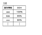
前記特定グループは、前記複数の2次電池毎のSOH(State Of Health)に基づいて分類されている、
付記5に記載の電池制御装置。
(付記7)
前記個数算出手段は、前記複数の2次電池毎のSOHに基づいて、前記予定個数及び前記既存個数を重み付けする、
付記1から6のいずれか1つに記載の電池制御装置。
(付記8)
各々独立して充放電を行う複数の2次電池と、
放電中の前記2次電池の放電電流量を個別に測定する測定手段と、
前記放電電流量に基づいて算出される前記2次電池毎の放電電流レートと、当該2次電池のSOC(State Of Charge)とに基づき、放電中の前記2次電池毎に、当該2次電池が一定の電池容量になるまでの所要時間を算出する時間算出手段と、
充電中の前記2次電池の充電電流量に基づいて算出される前記2次電池毎の充電電流レートと、当該2次電池のSOCと、前記所要時間とに基づき、前記所要時間内に満充電状態となる前記2次電池の予定個数を算出し、当該予定個数と既に満充電状態である2次電池の既存個数との合算値を算出する個数算出手段と、
前記合算値に基づいて前記充電電流レートを上げるか否かを判断する制御手段と、
を有する蓄電装置。
(付記9)
コンピュータが、
各々独立して充放電を行う複数の2次電池のうち、放電中の前記2次電池の放電電流量を個別に測定し、
前記放電電流量に基づいて算出される前記2次電池毎の放電電流レートと、当該2次電池のSOC(State Of Charge)とに基づき、放電中の前記2次電池毎に、当該2次電池が一定の電池容量になるまでの所要時間を算出し、
充電中の前記2次電池の充電電流量に基づいて算出される前記2次電池毎の充電電流レートと、当該2次電池のSOCと、前記所要時間とに基づき、前記所要時間内に満充電状態となる前記2次電池の予定個数を算出し、当該予定個数と既に満充電状態である2次電池の既存個数との合算値を算出し、
前記合算値に基づいて前記充電電流レートを上げるか否かを判断する、
ことを含む蓄電方法。
(付記10)
コンピュータを、
各々独立して充放電を行う複数の2次電池のうち、放電中の前記2次電池の放電電流量を個別に測定する測定手段、
前記放電電流量に基づいて算出される前記2次電池毎の放電電流レートと、当該2次電池のSOC(State Of Charge)とに基づき、放電中の前記2次電池毎に、当該2次電池が一定の電池容量になるまでの所要時間を算出する時間算出手段、
充電中の前記2次電池の充電電流量に基づいて算出される前記2次電池毎の充電電流レートと、当該2次電池のSOCと、前記所要時間とに基づき、前記所要時間内に満充電状態となる前記2次電池の予定個数を算出し、当該予定個数と既に満充電状態である2次電池の既存個数との合算値を算出する個数算出手段、
前記合算値に基づいて前記充電電流レートを上げるか否かを判断する制御手段、
として機能させるためのプログラム。
(付記11)
前記制御手段は、前記所要時間内に満充電状態とならない充電中の前記2次電池のうち、最も満充電に近い前記2次電池から順に、前記充電電流レートを上げる、
付記8に記載の蓄電装置。
(付記12)
前記制御手段は、2倍以上の上げ幅で前記充電電流レートを上げる、
付記8または11に記載の蓄電装置。
(付記13)
前記制御手段は、充電中の前記2次電池毎の充電完了時間と、前記所要時間とに基づいて、前記充電電流レートを下げる、
付記8、11、及び12のいずれか1つに記載の蓄電装置。
(付記14)
前記制御手段は、前記充電電流レートを優先して上げる対象とする特定グループに属する前記2次電池から順に、前記充電電流レートを上げる、
付記8、及び11から13のいずれか1つに記載の蓄電装置。
(付記15)
前記特定グループは、前記複数の2次電池毎のSOH(State Of Health)に基づいて分類されている、
付記14に記載の蓄電装置。
(付記16)
前記個数算出手段は、前記複数の2次電池毎のSOHに基づいて、前記予定個数及び前記既存個数を重み付けする、
付記8、及び11から15のいずれか1つに記載の蓄電装置。
(付記17)
前記コンピュータが、前記所要時間内に満充電状態とならない充電中の前記2次電池のうち、最も満充電に近い前記2次電池から順に、前記充電電流レートを上げる、
ことを含む付記9に記載の蓄電方法。
(付記18)
前記コンピュータが、2倍以上の上げ幅で前記充電電流レートを上げる、
ことを含む付記9または17に記載の蓄電方法。
(付記19)
前記コンピュータが、充電中の前記2次電池毎の充電完了時間と、前記所要時間とに基づいて、前記充電電流レートを下げる、
ことを含む付記9、17及び18のいずれか1つに記載の蓄電方法。
(付記20)
前記コンピュータが、前記充電電流レートを優先して上げる対象とする特定グループに属する前記2次電池から順に、前記充電電流レートを上げる、
ことを含む付記9、及び17から19のいずれか1つに記載の蓄電方法。
(付記21)
前記特定グループは、前記複数の2次電池毎のSOH(State Of Health)に基づいて分類されている、
ことを含む付記20に記載の蓄電方法。
(付記22)
前記コンピュータが、前記複数の2次電池毎のSOHに基づいて、前記予定個数及び前記既存個数を重み付けする、
ことを含む付記9、及び17から21のいずれか1つに記載の蓄電方法。
(付記23)
前記コンピュータを、前記所要時間内に満充電状態とならない充電中の前記2次電池のうち、最も満充電に近い前記2次電池から順に、前記充電電流レートを上げる手段、
として機能させるための付記10に記載のプログラム。
(付記24)
前記コンピュータを、2倍以上の上げ幅で前記充電電流レートを上げる手段、
として機能させるための付記10または23に記載のプログラム。
(付記25)
前記コンピュータを、充電中の前記2次電池毎の充電完了時間と、前記所要時間とに基づいて、前記充電電流レートを下げる手段、
として機能させるための付記10、23、及び24のいずれか1つに記載のプログラム。
(付記26)
前記コンピュータを、前記充電電流レートを優先して上げる対象とする特定グループに属する前記2次電池から順に、前記充電電流レートを上げる手段、
として機能させるための付記10、及び23から25のいずれか1つに記載のプログラム。
(付記27)
前記コンピュータを、前記複数の2次電池毎のSOH(State Of Health)に基づいて、前記複数の2次電池を特定グループに分類する手段、
として機能させるための付記26に記載のプログラム。
(付記28)
前記コンピュータを、前記複数の2次電池毎のSOHに基づいて、前記予定個数及び前記既存個数を重み付けする手段、
として機能させるための付記10、及び23から27のいずれか1つに記載のプログラム。 In addition, according to embodiment mentioned above, the following invention is disclosed.
(Appendix 1)
Among a plurality of secondary batteries that are charged and discharged independently, measuring means for individually measuring a discharge current amount of the secondary battery being discharged;
Based on the discharge current rate for each secondary battery calculated based on the discharge current amount and the SOC (State Of Charge) of the secondary battery, for each secondary battery being discharged, the secondary battery Time calculating means for calculating the time required until the battery reaches a certain battery capacity,
Fully charged within the required time based on the charging current rate for each secondary battery calculated based on the charging current amount of the secondary battery being charged, the SOC of the secondary battery, and the required time A number calculating means for calculating a planned number of the secondary batteries to be in a state and calculating a sum of the planned number and the existing number of secondary batteries that are already fully charged;
Control means for determining whether to increase the charging current rate based on the total value;
A battery control device.
(Appendix 2)
The control means increases the charging current rate in order from the secondary battery closest to full charge among the secondary batteries being charged that do not become fully charged within the required time.
The battery control device according to appendix 1.
(Appendix 3)
The control means increases the charging current rate by an increase of 2 times or more,
The battery control device according to appendix 1 or 2.
(Appendix 4)
The control means lowers the charging current rate based on a charging completion time for each secondary battery being charged and the required time.
The battery control device according to any one of appendices 1 to 3.
(Appendix 5)
The control means increases the charging current rate in order from the secondary battery belonging to a specific group to be targeted for increasing the charging current rate.
The battery control device according to any one of appendices 1 to 4.
(Appendix 6)
The specific group is classified based on SOH (State Of Health) for each of the plurality of secondary batteries.
The battery control device according to appendix 5.
(Appendix 7)
The number calculating means weights the planned number and the existing number based on SOH for each of the plurality of secondary batteries.
The battery control device according to any one of appendices 1 to 6.
(Appendix 8)
A plurality of secondary batteries that charge and discharge independently,
Measuring means for individually measuring the amount of discharge current of the secondary battery during discharge;
Based on the discharge current rate for each secondary battery calculated based on the discharge current amount and the SOC (State Of Charge) of the secondary battery, for each secondary battery being discharged, the secondary battery Time calculating means for calculating the time required until the battery reaches a certain battery capacity,
Fully charged within the required time based on the charging current rate for each secondary battery calculated based on the charging current amount of the secondary battery being charged, the SOC of the secondary battery, and the required time A number calculating means for calculating a planned number of the secondary batteries to be in a state and calculating a sum of the planned number and the existing number of secondary batteries that are already fully charged;
Control means for determining whether to increase the charging current rate based on the total value;
A power storage device.
(Appendix 9)
Computer
Among a plurality of secondary batteries that are charged and discharged independently, individually measuring the discharge current amount of the secondary battery being discharged,
Based on the discharge current rate for each secondary battery calculated based on the discharge current amount and the SOC (State Of Charge) of the secondary battery, for each secondary battery being discharged, the secondary battery Calculates the time required to reach a certain battery capacity,
Fully charged within the required time based on the charging current rate for each secondary battery calculated based on the charging current amount of the secondary battery being charged, the SOC of the secondary battery, and the required time Calculating the planned number of secondary batteries to be in a state, calculating the sum of the planned number and the existing number of secondary batteries that are already fully charged,
Determining whether to increase the charging current rate based on the total value;
A power storage method including the above.
(Appendix 10)
Computer
Measuring means for individually measuring a discharge current amount of the secondary battery being discharged among a plurality of secondary batteries that are charged and discharged independently;
Based on the discharge current rate for each secondary battery calculated based on the discharge current amount and the SOC (State Of Charge) of the secondary battery, for each secondary battery being discharged, the secondary battery Time calculation means for calculating the time required until the battery reaches a certain battery capacity,
Fully charged within the required time based on the charging current rate for each secondary battery calculated based on the charging current amount of the secondary battery being charged, the SOC of the secondary battery, and the required time A number calculating means for calculating a planned number of the secondary batteries that are in a state and calculating a sum of the planned number and the existing number of secondary batteries that are already fully charged;
Control means for determining whether to increase the charging current rate based on the total value;
Program to function as.
(Appendix 11)
The control means increases the charging current rate in order from the secondary battery closest to full charge among the secondary batteries being charged that do not become fully charged within the required time.
The power storage device according to appendix 8.
(Appendix 12)
The control means increases the charging current rate by an increase of 2 times or more,
The power storage device according to appendix 8 or 11.
(Appendix 13)
The control means lowers the charging current rate based on a charging completion time for each secondary battery being charged and the required time.
The power storage device according to any one of appendices 8, 11, and 12.
(Appendix 14)
The control means increases the charging current rate in order from the secondary battery belonging to a specific group to be targeted for increasing the charging current rate.
The power storage device according to any one of supplementary notes 8 and 11 to 13.
(Appendix 15)
The specific group is classified based on SOH (State Of Health) for each of the plurality of secondary batteries.
The power storage device according to appendix 14.
(Appendix 16)
The number calculating means weights the planned number and the existing number based on SOH for each of the plurality of secondary batteries.
The power storage device according to any one of supplementary notes 8 and 11 to 15.
(Appendix 17)
The computer increases the charging current rate in order from the secondary battery that is closest to full charge among the secondary batteries that are not fully charged within the required time.
The electricity storage method according to appendix 9, including the above.
(Appendix 18)
The computer increases the charging current rate by more than twice as much;
The electricity storage method according to appendix 9 or 17, including the above.
(Appendix 19)
The computer reduces the charging current rate based on a charging completion time for each of the secondary batteries being charged and the required time;
The electricity storage method according to any one of Supplementary Notes 9, 17, and 18.
(Appendix 20)
The computer increases the charging current rate in order from the secondary battery belonging to a specific group targeted for increasing the charging current rate.
The electricity storage method according to any one of Supplementary Notes 9 and 17 to 19, including:
(Appendix 21)
The specific group is classified based on SOH (State Of Health) for each of the plurality of secondary batteries.
The power storage method according to appendix 20, including the above.
(Appendix 22)
The computer weights the planned number and the existing number based on SOH for each of the plurality of secondary batteries.
The electricity storage method according to any one of Supplementary Note 9 and 17 to 21.
(Appendix 23)
Means for increasing the charging current rate in order from the secondary battery closest to full charge among the secondary batteries being charged that do not become fully charged within the required time in the computer;
The program according to
(Appendix 24)
Means for increasing the charging current rate at a rate of increase of 2 or more times for the computer;
The program according to
(Appendix 25)
Means for reducing the charge current rate based on the charge completion time for each of the secondary batteries being charged and the required time;
The program according to any one of
(Appendix 26)
Means for increasing the charging current rate in order from the secondary battery belonging to a specific group to which the computer is to be prioritized to increase the charging current rate;
The program according to any one of
(Appendix 27)
Means for classifying the plurality of secondary batteries into a specific group based on SOH (State Of Health) for each of the plurality of secondary batteries;
The program according to appendix 26 for functioning as:
(Appendix 28)
Means for weighting the planned number and the existing number based on SOH for each of the plurality of secondary batteries;
The program according to any one of
Claims (10)
- 各々独立して充放電を行う複数の2次電池のうち、放電中の前記2次電池の放電電流量を個別に測定する測定手段と、
前記放電電流量に基づいて算出される前記2次電池毎の放電電流レートと、当該2次電池のSOC(State Of Charge)とに基づき、放電中の前記2次電池毎に、当該2次電池が一定の電池容量になるまでの所要時間を算出する時間算出手段と、
充電中の前記2次電池の充電電流量に基づいて算出される前記2次電池毎の充電電流レートと、当該2次電池のSOCと、前記所要時間とに基づき、前記所要時間内に満充電状態となる前記2次電池の予定個数を算出し、当該予定個数と既に満充電状態である2次電池の既存個数との合算値を算出する個数算出手段と、
前記合算値に基づいて前記充電電流レートを上げるか否かを判断する制御手段と、
を有する電池制御装置。 Among a plurality of secondary batteries that are charged and discharged independently, measuring means for individually measuring a discharge current amount of the secondary battery being discharged;
Based on the discharge current rate for each secondary battery calculated based on the discharge current amount and the SOC (State Of Charge) of the secondary battery, for each secondary battery being discharged, the secondary battery Time calculating means for calculating the time required until the battery reaches a certain battery capacity,
Fully charged within the required time based on the charging current rate for each secondary battery calculated based on the charging current amount of the secondary battery being charged, the SOC of the secondary battery, and the required time A number calculating means for calculating a planned number of the secondary batteries to be in a state and calculating a sum of the planned number and the existing number of secondary batteries that are already fully charged;
Control means for determining whether to increase the charging current rate based on the total value;
A battery control device. - 前記制御手段は、前記所要時間内に満充電状態とならない充電中の前記2次電池のうち、最も満充電に近い前記2次電池から順に、前記充電電流レートを上げる、
請求項1に記載の電池制御装置。 The control means increases the charging current rate in order from the secondary battery closest to full charge among the secondary batteries being charged that do not become fully charged within the required time.
The battery control device according to claim 1. - 前記制御手段は、2倍以上の上げ幅で前記充電電流レートを上げる、
請求項1または2に記載の電池制御装置。 The control means increases the charging current rate by an increase of 2 times or more,
The battery control device according to claim 1. - 前記制御手段は、充電中の前記2次電池毎の充電完了時間と、前記所要時間とに基づいて、前記充電電流レートを下げる、
請求項1から3のいずれか1項に記載の電池制御装置。 The control means lowers the charging current rate based on a charging completion time for each secondary battery being charged and the required time.
The battery control apparatus of any one of Claim 1 to 3. - 前記制御手段は、前記充電電流レートを優先して上げる対象とする特定グループに属する前記2次電池から順に、前記充電電流レートを上げる、
請求項1から4のいずれか1項に記載の電池制御装置。 The control means increases the charging current rate in order from the secondary battery belonging to a specific group to be targeted for increasing the charging current rate.
The battery control apparatus of any one of Claim 1 to 4. - 前記特定グループは、前記複数の2次電池毎のSOH(State Of Health)に基づいて分類されている、
請求項5に記載の電池制御装置。 The specific group is classified based on SOH (State Of Health) for each of the plurality of secondary batteries.
The battery control device according to claim 5. - 前記個数算出手段は、前記複数の2次電池毎のSOHに基づいて、前記予定個数及び前記既存個数を重み付けする、
請求項1から6のいずれか1項に記載の電池制御装置。 The number calculating means weights the planned number and the existing number based on SOH for each of the plurality of secondary batteries.
The battery control apparatus of any one of Claim 1 to 6. - 各々独立して充放電を行う複数の2次電池と、
放電中の前記2次電池の放電電流量を個別に測定する測定手段と、
前記放電電流量に基づいて算出される前記2次電池毎の放電電流レートと、当該2次電池のSOC(State Of Charge)とに基づき、放電中の前記2次電池毎に、当該2次電池が一定の電池容量になるまでの所要時間を算出する時間算出手段と、
充電中の前記2次電池の充電電流量に基づいて算出される前記2次電池毎の充電電流レートと、当該2次電池のSOCと、前記所要時間とに基づき、前記所要時間内に満充電状態となる前記2次電池の予定個数を算出し、当該予定個数と既に満充電状態である2次電池の既存個数との合算値を算出する個数算出手段と、
前記合算値に基づいて前記充電電流レートを上げるか否かを判断する制御手段と、
を有する蓄電装置。 A plurality of secondary batteries that charge and discharge independently,
Measuring means for individually measuring the amount of discharge current of the secondary battery during discharge;
Based on the discharge current rate for each secondary battery calculated based on the discharge current amount and the SOC (State Of Charge) of the secondary battery, for each secondary battery being discharged, the secondary battery Time calculating means for calculating the time required until the battery reaches a certain battery capacity,
Fully charged within the required time based on the charging current rate for each secondary battery calculated based on the charging current amount of the secondary battery being charged, the SOC of the secondary battery, and the required time A number calculating means for calculating a planned number of the secondary batteries to be in a state and calculating a sum of the planned number and the existing number of secondary batteries that are already fully charged;
Control means for determining whether to increase the charging current rate based on the total value;
A power storage device. - コンピュータが、
各々独立して充放電を行う複数の2次電池のうち、放電中の前記2次電池の放電電流量を個別に測定し、
前記放電電流量に基づいて算出される前記2次電池毎の放電電流レートと、当該2次電池のSOC(State Of Charge)とに基づき、放電中の前記2次電池毎に、当該2次電池が一定の電池容量になるまでの所要時間を算出し、
充電中の前記2次電池の充電電流量に基づいて算出される前記2次電池毎の充電電流レートと、当該2次電池のSOCと、前記所要時間とに基づき、前記所要時間内に満充電状態となる前記2次電池の予定個数を算出し、当該予定個数と既に満充電状態である2次電池の既存個数との合算値を算出し、
前記合算値に基づいて前記充電電流レートを上げるか否かを判断する、
ことを含む蓄電方法。 Computer
Among a plurality of secondary batteries that are charged and discharged independently, individually measuring the discharge current amount of the secondary battery being discharged,
Based on the discharge current rate for each secondary battery calculated based on the discharge current amount and the SOC (State Of Charge) of the secondary battery, for each secondary battery being discharged, the secondary battery Calculates the time required to reach a certain battery capacity,
Fully charged within the required time based on the charging current rate for each secondary battery calculated based on the charging current amount of the secondary battery being charged, the SOC of the secondary battery, and the required time Calculating the planned number of secondary batteries to be in a state, calculating the sum of the planned number and the existing number of secondary batteries that are already fully charged,
Determining whether to increase the charging current rate based on the total value;
A power storage method including the above. - コンピュータを、
各々独立して充放電を行う複数の2次電池のうち、放電中の前記2次電池の放電電流量を個別に測定する測定手段、
前記放電電流量に基づいて算出される前記2次電池毎の放電電流レートと、当該2次電池のSOC(State Of Charge)とに基づき、放電中の前記2次電池毎に、当該2次電池が一定の電池容量になるまでの所要時間を算出する時間算出手段、
充電中の前記2次電池の充電電流量に基づいて算出される前記2次電池毎の充電電流レートと、当該2次電池のSOCと、前記所要時間とに基づき、前記所要時間内に満充電状態となる前記2次電池の予定個数を算出し、当該予定個数と既に満充電状態である2次電池の既存個数との合算値を算出する個数算出手段、
前記合算値に基づいて前記充電電流レートを上げるか否かを判断する制御手段、
として機能させるためのプログラム。 Computer
Measuring means for individually measuring a discharge current amount of the secondary battery being discharged among a plurality of secondary batteries that are charged and discharged independently;
Based on the discharge current rate for each secondary battery calculated based on the discharge current amount and the SOC (State Of Charge) of the secondary battery, for each secondary battery being discharged, the secondary battery Time calculation means for calculating the time required until the battery reaches a certain battery capacity,
Fully charged within the required time based on the charging current rate for each secondary battery calculated based on the charging current amount of the secondary battery being charged, the SOC of the secondary battery, and the required time A number calculating means for calculating a planned number of the secondary batteries that are in a state and calculating a sum of the planned number and the existing number of secondary batteries that are already fully charged;
Control means for determining whether to increase the charging current rate based on the total value;
Program to function as.
Priority Applications (3)
| Application Number | Priority Date | Filing Date | Title |
|---|---|---|---|
| RU2015121969/07A RU2600313C1 (en) | 2012-11-09 | 2013-11-01 | Device for controlling battery, energy accumulating device, energy accumulating method and program |
| EP13852443.4A EP2919361A4 (en) | 2012-11-09 | 2013-11-01 | Battery controller, power storage device, power storage method, and program |
| US14/440,526 US9735596B2 (en) | 2012-11-09 | 2013-11-01 | Battery control device, power storage device, power storage method, and program |
Applications Claiming Priority (2)
| Application Number | Priority Date | Filing Date | Title |
|---|---|---|---|
| JP2012247572A JP6068100B2 (en) | 2012-11-09 | 2012-11-09 | Battery control device, power storage device, power storage method, and program |
| JP2012-247572 | 2012-11-09 |
Publications (1)
| Publication Number | Publication Date |
|---|---|
| WO2014073475A1 true WO2014073475A1 (en) | 2014-05-15 |
Family
ID=50684581
Family Applications (1)
| Application Number | Title | Priority Date | Filing Date |
|---|---|---|---|
| PCT/JP2013/079689 WO2014073475A1 (en) | 2012-11-09 | 2013-11-01 | Battery controller, power storage device, power storage method, and program |
Country Status (5)
| Country | Link |
|---|---|
| US (1) | US9735596B2 (en) |
| EP (1) | EP2919361A4 (en) |
| JP (1) | JP6068100B2 (en) |
| RU (1) | RU2600313C1 (en) |
| WO (1) | WO2014073475A1 (en) |
Cited By (1)
| Publication number | Priority date | Publication date | Assignee | Title |
|---|---|---|---|---|
| US9883787B2 (en) | 2014-06-19 | 2018-02-06 | Olympus Corporation | Medical apparatus system |
Families Citing this family (8)
| Publication number | Priority date | Publication date | Assignee | Title |
|---|---|---|---|---|
| US10128656B2 (en) | 2014-06-17 | 2018-11-13 | Samsung Sdi Co., Ltd. | Power assist unit and power assist system |
| US9812901B2 (en) * | 2014-11-19 | 2017-11-07 | Thomas & Betts International Llc | Emergency lighting battery charger |
| WO2017094311A1 (en) * | 2015-12-01 | 2017-06-08 | ソニー株式会社 | Power management integrated circuit, electronic device, and method for controlling power management integrated circuit |
| US10416753B1 (en) * | 2015-12-10 | 2019-09-17 | Amazon Technologies, Inc. | Date-based computing device charge management |
| JP2021083133A (en) | 2018-03-12 | 2021-05-27 | 嵩 亀澤 | Constant voltage DC supply device |
| KR20210029878A (en) | 2019-09-06 | 2021-03-17 | 주식회사 엘지화학 | Battery management apparatus, battery management method, battery pack and electric vehicle |
| JP7191873B2 (en) * | 2020-01-17 | 2022-12-19 | 株式会社東芝 | Charge/discharge control device, charge/discharge system, charge/discharge control method, and charge/discharge control program |
| KR20240024696A (en) * | 2022-08-17 | 2024-02-26 | 주식회사 엘지에너지솔루션 | Apparatus for predicting charging time and operating method thereof |
Citations (6)
| Publication number | Priority date | Publication date | Assignee | Title |
|---|---|---|---|---|
| JPS59206680A (en) | 1983-05-10 | 1984-11-22 | Nippon Zosen Shinko Zaidan | Wave-energy-electric power generation device equipped with floating body |
| JPH02270270A (en) | 1989-04-11 | 1990-11-05 | Meidensha Corp | Operation of zinc-bromine battery |
| JP2001045677A (en) * | 1999-07-29 | 2001-02-16 | Sekisui Chem Co Ltd | Power supplying device using solar cell |
| JP2007508795A (en) * | 2003-10-08 | 2007-04-05 | エナージイ アンド エンジン テクノロジイ コーポレーション | Method and system for managing battery power |
| JP2009247108A (en) * | 2008-03-31 | 2009-10-22 | Furukawa Battery Co Ltd:The | Electric storage device and charging/discharging control method therefor |
| JP2012525117A (en) * | 2010-06-16 | 2012-10-18 | ジングァン チュ | Power supply device |
Family Cites Families (5)
| Publication number | Priority date | Publication date | Assignee | Title |
|---|---|---|---|---|
| US5422560A (en) * | 1991-09-30 | 1995-06-06 | Telcom Semiconductor, Inc. | Battery charger with battery detection circuit |
| RU2329582C2 (en) * | 2006-07-11 | 2008-07-20 | ФГУП "Северное проектно-конструкторское бюро" | Method of accumulators charge with their grouping in system by principle of capacities division |
| US7671559B2 (en) | 2007-07-31 | 2010-03-02 | Apple Inc. | Battery charging system and mobile and accessory devices |
| US20090243549A1 (en) * | 2008-03-31 | 2009-10-01 | Naoki Matsumura | Intelligent battery charging rate management |
| RU91482U1 (en) * | 2009-09-11 | 2010-02-10 | Некоммерческое партнерство "Инновации в электроэнергетике" (НП "ИНВЭЛ") | DEVICE FOR MULTI-POST CHARGING OF BATTERIES |
-
2012
- 2012-11-09 JP JP2012247572A patent/JP6068100B2/en not_active Expired - Fee Related
-
2013
- 2013-11-01 RU RU2015121969/07A patent/RU2600313C1/en not_active IP Right Cessation
- 2013-11-01 WO PCT/JP2013/079689 patent/WO2014073475A1/en active Application Filing
- 2013-11-01 EP EP13852443.4A patent/EP2919361A4/en not_active Withdrawn
- 2013-11-01 US US14/440,526 patent/US9735596B2/en not_active Expired - Fee Related
Patent Citations (6)
| Publication number | Priority date | Publication date | Assignee | Title |
|---|---|---|---|---|
| JPS59206680A (en) | 1983-05-10 | 1984-11-22 | Nippon Zosen Shinko Zaidan | Wave-energy-electric power generation device equipped with floating body |
| JPH02270270A (en) | 1989-04-11 | 1990-11-05 | Meidensha Corp | Operation of zinc-bromine battery |
| JP2001045677A (en) * | 1999-07-29 | 2001-02-16 | Sekisui Chem Co Ltd | Power supplying device using solar cell |
| JP2007508795A (en) * | 2003-10-08 | 2007-04-05 | エナージイ アンド エンジン テクノロジイ コーポレーション | Method and system for managing battery power |
| JP2009247108A (en) * | 2008-03-31 | 2009-10-22 | Furukawa Battery Co Ltd:The | Electric storage device and charging/discharging control method therefor |
| JP2012525117A (en) * | 2010-06-16 | 2012-10-18 | ジングァン チュ | Power supply device |
Non-Patent Citations (1)
| Title |
|---|
| See also references of EP2919361A4 |
Cited By (1)
| Publication number | Priority date | Publication date | Assignee | Title |
|---|---|---|---|---|
| US9883787B2 (en) | 2014-06-19 | 2018-02-06 | Olympus Corporation | Medical apparatus system |
Also Published As
| Publication number | Publication date |
|---|---|
| RU2600313C1 (en) | 2016-10-20 |
| EP2919361A1 (en) | 2015-09-16 |
| US9735596B2 (en) | 2017-08-15 |
| EP2919361A4 (en) | 2016-08-10 |
| JP2014096940A (en) | 2014-05-22 |
| US20150318726A1 (en) | 2015-11-05 |
| JP6068100B2 (en) | 2017-01-25 |
Similar Documents
| Publication | Publication Date | Title |
|---|---|---|
| JP6068100B2 (en) | Battery control device, power storage device, power storage method, and program | |
| KR101725701B1 (en) | Secondary cell system having plurality of cells, and method for distributing charge/discharge electric power or current | |
| JP6840525B2 (en) | Battery control method, battery control device, and battery pack | |
| JP4405558B2 (en) | Battery smoothing system and method using state of charge | |
| EP2824789B1 (en) | Frequency control method | |
| JP5975169B2 (en) | Charge / discharge device, charge / discharge control method, and program | |
| EP3078073B1 (en) | Device and method for controlling a plurality of cells of a battery | |
| US9257863B2 (en) | Charge and discharge control device and charge and discharge control method | |
| JP6945949B2 (en) | Storage battery system control device and control method | |
| US20150008884A1 (en) | Storage battery control apparatus, storage battery control method, and storage battery system | |
| JP2009081981A (en) | Charge state optimizing apparatus and battery pack system provided therewith | |
| JPWO2016051722A1 (en) | Power storage device, control device, power storage system, power storage device control method and control program | |
| JP2010028876A (en) | Charging/discharging system and portable computer | |
| JP6305526B2 (en) | Apparatus and method for maintaining charge of secondary battery | |
| EP3273524A1 (en) | Storage-battery management device, method, and program | |
| JP2013183509A (en) | Charge/discharge amount prediction system and charge/discharge amount prediction method | |
| TWI646750B (en) | Energy storage system and charging and discharging method | |
| JP2017225212A (en) | Charge/discharge control device | |
| JP6587466B2 (en) | Battery testing equipment | |
| KR101621123B1 (en) | Battery management system | |
| EP3116081A1 (en) | Received electrical power control method, received electrical power control device, and electrical instrument | |
| JP6447093B2 (en) | Power management system | |
| WO2023223618A1 (en) | Charge/discharge control device, charge/discharge control method, and program | |
| JP7387297B2 (en) | vehicle charging system | |
| JP6984460B2 (en) | Energy storage control device, energy storage control method, and energy storage control program |
Legal Events
| Date | Code | Title | Description |
|---|---|---|---|
| 121 | Ep: the epo has been informed by wipo that ep was designated in this application |
Ref document number: 13852443 Country of ref document: EP Kind code of ref document: A1 |
|
| REEP | Request for entry into the european phase |
Ref document number: 2013852443 Country of ref document: EP |
|
| WWE | Wipo information: entry into national phase |
Ref document number: 2013852443 Country of ref document: EP |
|
| WWE | Wipo information: entry into national phase |
Ref document number: 14440526 Country of ref document: US |
|
| NENP | Non-entry into the national phase |
Ref country code: DE |
|
| ENP | Entry into the national phase |
Ref document number: 2015121969 Country of ref document: RU Kind code of ref document: A |