WO2014073030A1 - 発電システム及び風力発電システム - Google Patents
発電システム及び風力発電システム Download PDFInfo
- Publication number
- WO2014073030A1 WO2014073030A1 PCT/JP2012/078687 JP2012078687W WO2014073030A1 WO 2014073030 A1 WO2014073030 A1 WO 2014073030A1 JP 2012078687 W JP2012078687 W JP 2012078687W WO 2014073030 A1 WO2014073030 A1 WO 2014073030A1
- Authority
- WO
- WIPO (PCT)
- Prior art keywords
- power
- wind
- generator
- voltage
- wind power
- Prior art date
- Legal status (The legal status is an assumption and is not a legal conclusion. Google has not performed a legal analysis and makes no representation as to the accuracy of the status listed.)
- Ceased
Links
Images






Classifications
-
- H—ELECTRICITY
- H02—GENERATION; CONVERSION OR DISTRIBUTION OF ELECTRIC POWER
- H02M—APPARATUS FOR CONVERSION BETWEEN AC AND AC, BETWEEN AC AND DC, OR BETWEEN DC AND DC, AND FOR USE WITH MAINS OR SIMILAR POWER SUPPLY SYSTEMS; CONVERSION OF DC OR AC INPUT POWER INTO SURGE OUTPUT POWER; CONTROL OR REGULATION THEREOF
- H02M7/00—Conversion of AC power input into DC power output; Conversion of DC power input into AC power output
- H02M7/42—Conversion of DC power input into AC power output without possibility of reversal
- H02M7/44—Conversion of DC power input into AC power output without possibility of reversal by static converters
- H02M7/48—Conversion of DC power input into AC power output without possibility of reversal by static converters using discharge tubes with control electrode or semiconductor devices with control electrode
- H02M7/483—Converters with outputs that each can have more than two voltages levels
-
- F—MECHANICAL ENGINEERING; LIGHTING; HEATING; WEAPONS; BLASTING
- F03—MACHINES OR ENGINES FOR LIQUIDS; WIND, SPRING, OR WEIGHT MOTORS; PRODUCING MECHANICAL POWER OR A REACTIVE PROPULSIVE THRUST, NOT OTHERWISE PROVIDED FOR
- F03D—WIND MOTORS
- F03D9/00—Adaptations of wind motors for special use; Combinations of wind motors with apparatus driven thereby; Wind motors specially adapted for installation in particular locations
- F03D9/10—Combinations of wind motors with apparatus storing energy
-
- F—MECHANICAL ENGINEERING; LIGHTING; HEATING; WEAPONS; BLASTING
- F03—MACHINES OR ENGINES FOR LIQUIDS; WIND, SPRING, OR WEIGHT MOTORS; PRODUCING MECHANICAL POWER OR A REACTIVE PROPULSIVE THRUST, NOT OTHERWISE PROVIDED FOR
- F03D—WIND MOTORS
- F03D9/00—Adaptations of wind motors for special use; Combinations of wind motors with apparatus driven thereby; Wind motors specially adapted for installation in particular locations
- F03D9/10—Combinations of wind motors with apparatus storing energy
- F03D9/11—Combinations of wind motors with apparatus storing energy storing electrical energy
-
- F—MECHANICAL ENGINEERING; LIGHTING; HEATING; WEAPONS; BLASTING
- F03—MACHINES OR ENGINES FOR LIQUIDS; WIND, SPRING, OR WEIGHT MOTORS; PRODUCING MECHANICAL POWER OR A REACTIVE PROPULSIVE THRUST, NOT OTHERWISE PROVIDED FOR
- F03D—WIND MOTORS
- F03D9/00—Adaptations of wind motors for special use; Combinations of wind motors with apparatus driven thereby; Wind motors specially adapted for installation in particular locations
- F03D9/20—Wind motors characterised by the driven apparatus
- F03D9/25—Wind motors characterised by the driven apparatus the apparatus being an electrical generator
- F03D9/255—Wind motors characterised by the driven apparatus the apparatus being an electrical generator connected to electrical distribution networks; Arrangements therefor
-
- H—ELECTRICITY
- H02—GENERATION; CONVERSION OR DISTRIBUTION OF ELECTRIC POWER
- H02J—ELECTRIC POWER NETWORKS; CIRCUIT ARRANGEMENTS OR SYSTEMS FOR SUPPLYING OR DISTRIBUTING ELECTRIC POWER; SYSTEMS FOR STORING ELECTRIC ENERGY
- H02J3/00—Circuit arrangements for AC mains or AC distribution networks
- H02J3/38—Arrangements for feeding a single network from two or more generators or sources in parallel; Arrangements for feeding already energised networks from additional generators or sources in parallel
- H02J3/381—Dispersed generators
-
- H—ELECTRICITY
- H02—GENERATION; CONVERSION OR DISTRIBUTION OF ELECTRIC POWER
- H02M—APPARATUS FOR CONVERSION BETWEEN AC AND AC, BETWEEN AC AND DC, OR BETWEEN DC AND DC, AND FOR USE WITH MAINS OR SIMILAR POWER SUPPLY SYSTEMS; CONVERSION OF DC OR AC INPUT POWER INTO SURGE OUTPUT POWER; CONTROL OR REGULATION THEREOF
- H02M7/00—Conversion of AC power input into DC power output; Conversion of DC power input into AC power output
- H02M7/42—Conversion of DC power input into AC power output without possibility of reversal
- H02M7/44—Conversion of DC power input into AC power output without possibility of reversal by static converters
- H02M7/48—Conversion of DC power input into AC power output without possibility of reversal by static converters using discharge tubes with control electrode or semiconductor devices with control electrode
- H02M7/483—Converters with outputs that each can have more than two voltages levels
- H02M7/4835—Converters with outputs that each can have more than two voltages levels comprising two or more cells, each including a switchable capacitor, the capacitors having a nominal charge voltage which corresponds to a given fraction of the input voltage, and the capacitors being selectively connected in series to determine the instantaneous output voltage
-
- H—ELECTRICITY
- H02—GENERATION; CONVERSION OR DISTRIBUTION OF ELECTRIC POWER
- H02M—APPARATUS FOR CONVERSION BETWEEN AC AND AC, BETWEEN AC AND DC, OR BETWEEN DC AND DC, AND FOR USE WITH MAINS OR SIMILAR POWER SUPPLY SYSTEMS; CONVERSION OF DC OR AC INPUT POWER INTO SURGE OUTPUT POWER; CONTROL OR REGULATION THEREOF
- H02M7/00—Conversion of AC power input into DC power output; Conversion of DC power input into AC power output
- H02M7/42—Conversion of DC power input into AC power output without possibility of reversal
- H02M7/44—Conversion of DC power input into AC power output without possibility of reversal by static converters
- H02M7/48—Conversion of DC power input into AC power output without possibility of reversal by static converters using discharge tubes with control electrode or semiconductor devices with control electrode
- H02M7/483—Converters with outputs that each can have more than two voltages levels
- H02M7/49—Combination of the output voltage waveforms of a plurality of converters
-
- H—ELECTRICITY
- H02—GENERATION; CONVERSION OR DISTRIBUTION OF ELECTRIC POWER
- H02J—ELECTRIC POWER NETWORKS; CIRCUIT ARRANGEMENTS OR SYSTEMS FOR SUPPLYING OR DISTRIBUTING ELECTRIC POWER; SYSTEMS FOR STORING ELECTRIC ENERGY
- H02J2101/00—Supply or distribution of decentralised, dispersed or local electric power generation
- H02J2101/20—Dispersed power generation using renewable energy sources
- H02J2101/28—Wind energy
-
- H—ELECTRICITY
- H02—GENERATION; CONVERSION OR DISTRIBUTION OF ELECTRIC POWER
- H02P—CONTROL OR REGULATION OF ELECTRIC MOTORS, ELECTRIC GENERATORS OR DYNAMO-ELECTRIC CONVERTERS; CONTROLLING TRANSFORMERS, REACTORS OR CHOKE COILS
- H02P2101/00—Special adaptation of control arrangements for generators
- H02P2101/15—Special adaptation of control arrangements for generators for wind-driven turbines
-
- Y—GENERAL TAGGING OF NEW TECHNOLOGICAL DEVELOPMENTS; GENERAL TAGGING OF CROSS-SECTIONAL TECHNOLOGIES SPANNING OVER SEVERAL SECTIONS OF THE IPC; TECHNICAL SUBJECTS COVERED BY FORMER USPC CROSS-REFERENCE ART COLLECTIONS [XRACs] AND DIGESTS
- Y02—TECHNOLOGIES OR APPLICATIONS FOR MITIGATION OR ADAPTATION AGAINST CLIMATE CHANGE
- Y02E—REDUCTION OF GREENHOUSE GAS [GHG] EMISSIONS, RELATED TO ENERGY GENERATION, TRANSMISSION OR DISTRIBUTION
- Y02E10/00—Energy generation through renewable energy sources
- Y02E10/70—Wind energy
- Y02E10/72—Wind turbines with rotation axis in wind direction
-
- Y—GENERAL TAGGING OF NEW TECHNOLOGICAL DEVELOPMENTS; GENERAL TAGGING OF CROSS-SECTIONAL TECHNOLOGIES SPANNING OVER SEVERAL SECTIONS OF THE IPC; TECHNICAL SUBJECTS COVERED BY FORMER USPC CROSS-REFERENCE ART COLLECTIONS [XRACs] AND DIGESTS
- Y02—TECHNOLOGIES OR APPLICATIONS FOR MITIGATION OR ADAPTATION AGAINST CLIMATE CHANGE
- Y02E—REDUCTION OF GREENHOUSE GAS [GHG] EMISSIONS, RELATED TO ENERGY GENERATION, TRANSMISSION OR DISTRIBUTION
- Y02E10/00—Energy generation through renewable energy sources
- Y02E10/70—Wind energy
- Y02E10/76—Power conversion electric or electronic aspects
-
- Y—GENERAL TAGGING OF NEW TECHNOLOGICAL DEVELOPMENTS; GENERAL TAGGING OF CROSS-SECTIONAL TECHNOLOGIES SPANNING OVER SEVERAL SECTIONS OF THE IPC; TECHNICAL SUBJECTS COVERED BY FORMER USPC CROSS-REFERENCE ART COLLECTIONS [XRACs] AND DIGESTS
- Y02—TECHNOLOGIES OR APPLICATIONS FOR MITIGATION OR ADAPTATION AGAINST CLIMATE CHANGE
- Y02E—REDUCTION OF GREENHOUSE GAS [GHG] EMISSIONS, RELATED TO ENERGY GENERATION, TRANSMISSION OR DISTRIBUTION
- Y02E70/00—Other energy conversion or management systems reducing GHG emissions
- Y02E70/30—Systems combining energy storage with energy generation of non-fossil origin
Definitions
- the present invention relates to a power generation system and a wind power generation system, and, for example, a power generation system and a wind power generation system suitable for generating a generator voltage different from the grid voltage of an electric power system, such as a wind power generator About.
- Patent Literature 1 is given as a background art related to a wind power generation system which is a technical field of the present invention.
- the patent document 1 describes a natural energy utilization power generation system such as a wind power generation system, and adjusts the power output from the wind power generator with a power converter for forward conversion and reverse conversion including a power storage device.
- a storage unit is provided in a direct current portion of a power converter that has a configuration connecting a generator to an electric power system and a wind power generation system, and the charge / discharge amount of the storage unit is reduced to reduce the loss generated by the storage unit. Is described.
- Patent Document 1 a permanent magnet generator, a secondary excitation generator, or an induction generator is used as a wind power generator employed in a wind power generation system, and further, a power storage device is used. The specific configuration of the provided power converter is described.
- the wind power generation system can generate power for a wide range of wind speeds and can be stably connected to the electric power system, and further reduce loss during charge and discharge. Fluctuation of the active power output to the power system can be suppressed by utilizing the illustrated power storage device.
- patent document 2 as background art related to others.
- the rotor of the synchronous generator in order to improve the utilization factor of the wind turbine and to suppress the fluctuation of the output power due to the fluctuation of the output of the wind turbine, the rotor of the synchronous generator is connected to the shaft of the wind turbine and the synchronous generator is fixed. And a reverse converter connected to the power converter and connected to the electric power system, and the generated power of the variable frequency of the synchronous generator is converted to DC power by the forward converter.
- Patent Document 2 As in Patent Document 1, it is needless to say that the wind power generation system and the power system can be stably linked, and of course the active power output to the current system using a chargeable / dischargeable secondary battery. Fluctuation can be suppressed.
- Patent Document 1 described above describes an example in which a secondary excitation generator is used as a wind power generator of a wind power generation system.
- a grid-side power converter for converting AC power obtained from the secondary excitation generator into DC power, and power converting this DC power into AC power
- a rotor side power converter is provided.
- the power supplied to the rotor excitation system of the secondary excitation generator is controlled such that the frequency of the generator voltage obtained from the generator stator side matches the frequency of the electric power system. Also, at this time, the voltage of the generator stator matches the voltage of the power system because the generator stator is connected to the power system.
- the secondary excitation generator supplies power to the excitation system of the generator rotor in order to stably connect the variable frequency wind power generator that generates power to the widely changing wind speed to the power system.
- the generator power is obtained from the generator stator connected to the power system, and the frequency of the generator voltage is adjusted to match the frequency of the power system.
- a secondary excitation generator has a generator stator and It is possible to directly connect to the power system.
- stator voltage of the secondary excitation generator in the wind power generation system rises as the wind speed increases.
- stator current of the secondary excitation generator is set so that the voltage difference between the generator stator voltage and the power system voltage disappears. It shows a generator output characteristic that changes and eventually the generated power which is the generator output rises.
- the secondary excitation generator is the generator rotor rotation speed and the grid of the electric power system.
- generator power is output not only from the generator stator but also from the generator rotor.
- the generator voltage of the secondary excitation generator is the same as the voltage of the power grid.
- the power output from the generator stator decreases. Since the power of the rotor excitation system of the secondary excitation generator is supplied from the power output from the generator stator when the secondary excitation generator is below the synchronous rotation speed, the degree of reduction of the wind speed In some cases, the stator voltage of the secondary excitation generator can not be maintained at the power system voltage.
- the secondary excitation generator has a wind speed to some extent, the low wind speed causes a shortage of generated power, and the power system is disconnected.
- the frequency of the voltage and current of the synchronous generator also changes because the rotational speed of the synchronous generator changes with the wind speed.
- the frequency of the power system does not necessarily coincide with the frequency of the voltage and current of the wind power generator, the wind power generator can not be directly linked to the power system.
- the power generated by the synchronous generator is temporarily forward converted from AC power to DC power by the forward converter, and then matched with the grid frequency and grid voltage by the reverse converter.
- the secondary battery is connected in parallel between the forward converter and the reverse converter, and the fluctuation of the active power of the forward converter caused by the change of the generated power of the wind power generator fluctuated by the wind speed change, and further
- the secondary battery is constantly charge / discharge controlled so as to suppress the power fluctuation of the fluctuation of the active power output from the reverse converter to the power system.
- forward converters and reverse converters which are power converters
- forward converters and reverse converters can be replaced by a plurality of series-connected power converters having storage batteries, and as a result, a low-voltage power converter can be applied. Therefore, it is expected that the power conversion loss of each power converter can be reduced.
- the generated voltage of the wind power generator changes depending on the wind speed, and in particular, when the wind speed is low, the generator voltage generated by the wind power generator is reduced. Can not be obtained.
- the wind energy required for power generation may not be sufficiently input to the wind power generator.
- the generated voltage of the wind power generator is greater than the grid voltage of the power grid. It gets lower.
- the power generation current of the wind power generator is reduced, which results in a voltage difference between the power generation voltage and the grid voltage. If the wind speed is adjusted but the wind speed is lower and the generator voltage and the grid voltage can not be adjusted, that is, if the generated current can not be obtained, the wind power generator operates from the generator to the motor. The wind power generator will be disconnected from the power grid to avoid motor operation.
- Patent Documents 1 and 2 do not take into consideration at all the above-mentioned problems at low wind speed where the wind speed is reduced.
- the present invention has been made in view of the above-mentioned point, and the object of the present invention is to be able to stably connect the generator and the electric power system even at the time of low wind speed when the wind speed is reduced. It is an object of the present invention to provide a power generation system and a wind power generation system capable of extending the operable range at low wind speeds of the above and thereby improving the utilization factor of the power generation facility.
- a power generation system includes: a generator; and a plurality of power conversions having one end connected to the generator and the other end connected to a power system, and having a storage device.
- Device, the generator and the plurality of power conversion devices are connected in series, and when a voltage difference occurs between the generator and the power system, the power storage device is controlled by controlling the power conversion device.
- the output voltage on the power system side of the power conversion device is adjusted so as to charge and discharge the battery to eliminate the voltage difference.
- a wind power generator driven by a wind turbine that rotates in response to wind and one end is connected to the wind power generator, and the other end is A plurality of power converters connected to a power system and having a power storage device, the stator of the wind power generator and the plurality of power converters are connected in series, and the wind power generator and the power system are connected
- the output voltage of the power system side of the power conversion device is adjusted so as to charge and discharge the power storage device and eliminate the voltage difference.
- a wind power generator driven by a wind turbine rotating in response to wind and a plurality of power conversions having one end connected to the wind power generator and the other end connected to the power system and having a power storage device The system; and a rotor excitation system including a grid-side power converter that converts AC power from the wind power generator into DC power and a rotor-side power converter that converts DC power to AC power;
- the stator of the wind power generator and the plurality of power conversion devices are connected in series, and one end of the rotor excitation system is connected to the rotor of the wind power generator, and the other end of the rotor excitation system
- the power system on the grid side is connected between the power system and the power conversion device located closest to the power system, and a voltage difference occurs between the wind power generator and the power system
- controlling the power conversion device to adjust the output voltage of the power system side of the power conversion device so as to charge / discharge the power storage device and eliminate the voltage difference
- the generator and the electric power system can be stably interconnected even at low wind speeds where the wind speed is reduced, and the operable range at low wind speeds of the power generation system can be expanded. There is an effect that the utilization factor of the power generation facility can be improved.
- Example 1 of the wind power generation system of this invention It is a figure which shows Example 1 of the wind power generation system of this invention. It is a figure which shows the structure of the power converter device employ
- Example 1 of the wind power generation system of this invention is shown.
- FIG. 1 uses a secondary excitation generator as a wind power generator of a wind power generation system, and adjusts the voltage of the generator voltage different from the grid voltage of the electric power system using a power conversion unit provided with a storage device.
- a secondary excitation generator as a wind power generator of a wind power generation system
- adjusts the voltage of the generator voltage different from the grid voltage of the electric power system using a power conversion unit provided with a storage device.
- These are examples of the wind power generation system which can connect a wind power generation system and an electric power system.
- a power system is three-phase alternating current normally, in order to connect a wind power generation system to an electric power system, it is necessary to also comprise a wind power generation system by three-phase alternating current.
- a wind power generation system by three-phase alternating current.
- only one phase of the three-phase alternating current is representatively shown, and the configuration and operation of the wind power generation system will be described below.
- the wind turbine 1 that rotates in response to the wind is connected to the rotor of the wind power generator 3 via the speed increasing gear 2.
- the rotor of the wind power generator 3 receives supply of excitation power necessary for power generation from a rotor excitation system of the wind power generator 3.
- the stator of the wind power generator 3 is connected to the electric power system 500 via the plurality of power conversion devices 8 provided with the power storage device 9. And these power converters 8 are connected in series with the wind power generator 3.
- the plurality of power conversion devices 8 provided with the storage device 9 function as a variable voltage source, and the power system of the power generation system is obtained by adding the output voltage of the power conversion device 8 to the voltage of the wind power generator 3.
- the voltage is adjusted so as to eliminate the voltage difference with the system voltage of 500.
- the wind power generator 3 is stably linked to the power system 500.
- the rotor excitation system of the wind power generator 3 includes a grid-side power converter 5 that converts AC power obtained from the secondary excitation generator that is the wind power generator 3 into DC power. It is comprised from the rotor side power converter 4 which carries out electric power conversion of the direct-current power power-converted by the system side power converter 5 to alternating current power, and the direct current capacitor 6 of a direct current link part.
- the grid-side power converter 5 is typically a PWM converter, and is connected between the stator of the wind power generator 3 and the power conversion device 8 equipped with the storage device 9 via a line resistance and reactance 7, It has a function of converting power into DC power.
- the DC power which is the output of the grid-side power converter 5 becomes the input of the DC capacitor 6 of the DC link unit connected to the grid-side power converter 5.
- this DC capacitor 6 is connected to the rotor side power converter 4 which is typically a PWM converter.
- the rotor-side power converter 4 has a function of converting DC power into AC power, and the converted AC power is frequency-adjusted and supplied to the rotor of the wind power generator 3 as generator excitation power. Be done.
- the grid-side power converter 5 on the power grid 500 side is installed for the purpose of rectifying the DC voltage of the DC link portion of the rotor excitation system.
- a DC voltage control system is provided. That is, the difference between the DC voltage setting value S4 of the DC link portion and the measured value S2 of the DC voltage is determined by the subtractor.
- the set current value for the grid-side power converter 5 is calculated by the DC voltage controller 15 of the DC link unit. Specifically, in dq coordinate axis representation, it is calculated as a set value of d-axis current that affects effective power and a set value of reactive power control that controls q-axis current, and the power factor of the wind power generation system Applied to control. Based on these current setting values, the current controller 16 calculates a PWM control signal for the grid side power converter 5.
- the wind turbine 1 used in the wind power generation system can use wind energy as the rotational energy of the wind turbine 1 to the maximum, and the appropriate maximum value of the rotation speed of the wind turbine 1 is determined depending on the wind speed. Therefore, the rotational speed of the wind turbine 1 is determined by calculating the maximum power point (MPP) based on the wind speed value received by the wind turbine 1.
- the rotor-side power converter 4 connected to the rotor of the wind power generator 3 is the maximum power point (MPP) of rotational energy (mechanical energy) input from the wind turbine 1 whose rotational speed changes due to the widely varying wind speed To control the wind power generator 3 to the optimum rotational speed.
- control method of the rotor-side power converter 4 is a multiplex control system including a control system related to the rotor rotational speed, power and current of the wind power generator 3. Note that power control can be omitted by implementing non-interference current control.
- the rotor speed signal referred to by the speed control system is, as described above, a maximum power point (MPP) based on the measured wind speed S1. It is determined by the computing unit 11 to calculate.
- the speed control system 12 calculates a reference effective power value to be input to the power control system. Since the reactive power signal necessary for the wind power generation system is input from the grid side power converter 5, the power control system 13 of the rotor side power converter 4 sets the reference reactive power value to "0". Ru.
- a deviation from the active power value and the reactive power value is calculated by the subtractor with respect to the reference value of the active power and the reference value S5 of the reactive power calculated by the power calculation unit 17, and is used as an input of the power control system 13.
- the power control system 13 calculates a reference current value for controlling the current of the rotor.
- the current control system 14 calculates the PWM control signal for the rotor side power converter 4 so as to make the power reference value follow by controlling the rotor current based on the reference current value.
- the operation of the rotor excitation system changes as follows. That is, when the rotor rotational speed of the wind power generator 3 is a synchronous rotational speed that is the same as the grid frequency of the electric power system 500, the rotor excitation system transmits DC power to the rotor of the wind power generator 3. Supply. In this state, since the internal magnetic flux of the wind power generator 3 changes at the synchronous rotation speed, the stator of the wind power generator 3 that outputs to the electric power system 500 generates power at a frequency synchronized with the electric power system 500. Machine voltage is generated.
- the rotor side power converter 4 of the rotor excitation system is controlled to control the frequency corresponding to the rotor rotational speed of the wind power generator 3, specifically, the frequency of the power obtained from the stator of the wind power generator 3.
- the excitation current frequency of the rotor of the wind power generator 3 is adjusted so that the synchronous rotation speed is obtained, and surplus power generated inside the wind power generator 3 is transmitted from the rotor of the wind power generator 3 to the rotor side It takes out directly via the power converter 4.
- the frequency of the surplus power extracted from the rotor-side power converter 4 of the wind power generator 3 is different from the grid frequency
- the AC power is converted to DC power by the rotor-side power converter 4 and then the DC link Power is converted from DC power to AC power of the frequency of the power system 500 by the grid-side power converter 5 via the unit.
- the wind power generator 3 When the wind speed decreases and the rotor rotational speed of the wind power generator 3 falls below the synchronous speed, if DC power is still supplied to the rotor of the wind power generator 3, the wind power generator 3 The power obtained from the stator is different from the grid frequency, and the power generated by the wind power generator 3 can be stably supplied to the power grid 500 as in the case where the rotor rotational speed of the wind power generator 3 increases. Can not.
- the rotor side power converter 4 of the rotor excitation system is controlled to control the frequency corresponding to the rotor rotational speed of the wind power generator 3, specifically, the power obtained from the stator of the wind power generator 3.
- the excitation current frequency of the rotor of the wind power generator 3 is adjusted so that the frequency becomes the synchronous rotation number, excitation power is supplied to the rotor of the wind power generator 3, and generated electricity from the stator of the wind power generator 3 Take out.
- the excitation current supplied to the rotor of the wind power generator 3 converts the AC power obtained from the stator of the wind power generator 3 into DC power by the grid-side power converter 5, and then the DC link unit The DC power is converted into AC power by the rotor side power converter 4 and obtained.
- the basic power generation characteristics of the wind power generator 3 using the secondary excitation generator with respect to the wind speed change described above can be shown as follows.
- the generated voltage of the wind power generator 3 is still insufficient, and therefore no power supply from the wind power generator 3 to the electric power grid 500 occurs.
- the wind speed further increases and the excitation current is supplied to the rotor of the wind power generator 3 by the rotor excitation system and the voltage of the wind power generator 3 rises to about the power grid, the wind power generator 3 and the power grid 500 Interconnection becomes possible, and the power generated by the wind power generator 3 is supplied to the electric power system 500.
- the rotational speed of the rotor of the wind power generator 3 is lower than the grid frequency, and the power generated by the wind power generator 3 is taken out from the stator of the wind power generator 3.
- the voltage of the wind power generator 3 is adjusted by the grid voltage of the power grid 500, so the current of the wind power generator 3 increases.
- the power obtained from the wind power generator 3 will increase.
- the frequency of the excitation current of the rotor of the wind power generator 3 decreases as the rotor rotational speed of the wind power generator 3 increases.
- the excitation current supplied to the rotor of the wind power generator 3 is supplied as DC power. Furthermore, when the rotor rotational speed of the wind power generator 3 rises above the synchronous rotational speed, the excitation current of the rotor of the wind power generator 3 changes from direct current to alternating current, and its frequency increases. The power generated by the wind power generator 3 also increases, but the generated power is obtained not only from the stator of the wind power generator 3, but also from the rotor of the wind power generator 3.
- the wind power generator 3 using the secondary excitation generator is controlled by the excitation current control by the rotor excitation system of the wind power generator 3 and the stator voltage of the wind power generator 3 Is maintained at the grid voltage of the power system 500, but the power obtained from the wind power generator 3 decreases.
- the DC voltage control of the DC link part of the rotor excitation system of the wind power generator 3 lowering the setting value of the DC voltage generates a voltage difference with the grid voltage through the grid side power converter 5. Stable operation becomes difficult.
- a variable voltage source is connected in series between the wind power generator 3 and the power grid 500 to compensate for the voltage difference between the generated voltage of the wind power generator 3 and the grid voltage of the power grid 500.
- the wind power generator 3 and the power system 500 can be stably interconnected even at low wind speeds.
- the configuration is as follows. That is, on the power output side of the stator of the wind power generator 3, a plurality of power conversion devices 8 including the power storage device 9 are connected in series to the wind power generator 3 and interconnected with the power system 500. As shown in FIG. 2, the plurality of power conversion devices 8 are typically configured by a PWM inverter having a capacitor 81 for DC voltage stabilization. Moreover, since these power conversion devices 8 are provided with the power storage devices 9 and the power conversion device 8 outputs a voltage using the individual power storage devices 9 as a voltage source by the switch operation of the PWM inverter, The whole will act as a variable voltage source.
- the operation of the plurality of serially connected power electronics devices 8 is controlled by the power electronics device controller 10.
- the input signals of the power conversion device controller 10 are the voltage S3 of the wind power generator 3, the set values S7 of the active power and the reactive power, the grid voltage S9 of the power grid 500, and the grid current S8.
- the output signal of the power conversion device 8 is the switch operation request signal S6 of ON and OFF of the PWM inverter constituting the power conversion device 8.
- the set value S7 of the active power needs to consider the generated power obtained from the wind power generator 3, and is set as a total value of the active power output from the wind power generator 3 and the power conversion device 8. Further, since the power conversion device 8 performs active power control, reactive power is set to “0”.
- the control purpose of the power conversion device controller 10 is to adjust the voltage amplitude by adding the output voltage of the power conversion device 8 using the storage device 9 as a voltage source to the stator voltage of the wind power generator 3 And to match.
- the stator voltage of the wind power generator 3 is an alternating current
- the voltage of the power system 500 is also an alternating current.
- each power storage device 9 outputs a constant voltage. Therefore, a plurality of constant voltage waveforms are generated by the ON and OFF switch operations of the PWM inverters of the plurality of power conversion devices 8 connected in series to the wind power generator 3, and finally, the plurality of power conversions are performed.
- the addition of the output voltage waveforms of device 8 produces an alternating voltage waveform of the same frequency as the voltage of power system 500.
- the ON / OFF switch operation of the PWM inverter of the power conversion device 8 is a modulation wave voltage which is a target voltage waveform A and a threshold voltage for turning ON / OFF the PWM inverter as shown in FIG. It compares and determines with a certain carrier signal.
- the modulation wave voltage signal is divided into multiple levels by the number of power conversion devices 8 (see FIG. 5), and the voltage handled by each power conversion device 8
- the ON and OFF operations of the PWM inverter of the corresponding power conversion device 8 are controlled by comparing the voltage levels with the plurality of carrier signals shifted in level. That is, as shown in FIG.
- the target modulation wave voltage signal is PWM-modulated at a plurality of voltage levels V1 to V5.
- the PWM inverters of the plurality of power conversion devices 8 are turned on and off with respect to the target modulation wave voltage signal, thereby obtaining PWM-modulated voltages at a plurality of voltage levels. That is, since a plurality of power conversion devices 8 are connected in series, as shown in FIG. 6, the total voltage V from the power conversion device 8 is output corresponding to the modulation wave voltage signal.
- the modulation wave voltage signal targeted by the power conversion device 8 is calculated as follows. That is, the modulation wave voltage signal depends on the active power and the reactive power output from the power conversion device 8, and also depends on the current signal of the power system 500. That is, as shown in FIG. 3, based on the set values S7 of the active power and the reactive power, the grid current S8 and the grid voltage S9 of the power system 500, the modulation wave voltage generation unit 32 performs active power control calculation to perform power conversion.
- the voltage signal for outputting the active power from the device 8, ie, the modulation wave voltage signal S31 is calculated.
- the phase and frequency of the system voltage are determined by the phase detection unit 31, and are used for the modulation wave voltage signal calculation for active power control.
- the stator voltage signal S3 which is the output of the wind power generator 3 is added to the target modulation wave voltage signal S31 from the power conversion device 8 calculated by the modulation wave voltage generation unit 32 to obtain a corrected modulation wave voltage signal S32.
- the corrected modulation wave voltage signal S32 is standardized by the addition signal S71 of the voltage of the storage device 9, and is output to the PWM inverter 33. Therefore, as described above, the voltage comparison unit 34 compares the standardized modulation wave voltage signal S33 with the carrier wave signal whose voltage level has been shifted, and the PWM inverter of the power conversion device 8 corresponding to each is compared.
- the control signal S34 of the ON and OFF operation of is generated.
- the power generation characteristics of the wind power generation system of the present invention are substantially equivalent to that of a wind power generation system using a conventional wind power generator using a secondary excitation generator.
- a plurality of power conversion devices 8 provided with a storage device 9 are connected in series to a wind power generator 3 using a secondary excitation generator, and the power system 500 is connected to the power system 500 via these power conversion devices 8. 7 to 9 show an example of voltage waveforms when the system is used.
- the frequency of each voltage waveform is the same, and although not shown, between the wind power generator 3 and the power conversion device 8 and the power system 500 due to the phase difference between voltage and current. Active power flow occurs.
- the stator voltage of the wind power generator 3 shown in FIG. 7 is determined by the operation of the rotor excitation system of the wind power generator 3 regardless of the rotor rotational speed of the wind power generator 3.
- the power is output as the power of the wind power generator 3 at the synchronous rotation number (frequency).
- the stator voltage of the wind power generator 3 is maintained lower than the grid voltage of the electric power system 500 by the DC voltage control of the DC link part of the rotor excitation system.
- the state in which the voltage of the wind power generator 3 is maintained low corresponds to the case where the wind speed decreases and the voltage of the wind power generator 3 decreases so that the grid voltage can not be maintained.
- the total voltage output from the plurality of power conversion devices 8 provided with the storage device 9 is shown in FIG.
- the voltage waveform output from the power conversion device 8 is obtained by PWM-modulating the modulation wave voltage waveform with a plurality of levels using the power storage device 9 as a DC power supply. Therefore, in actuality, since the power converter 8 outputs different voltage levels, the total voltage becomes a stepped voltage waveform.
- the stepped voltage waveform is shown as a waveform after being formed by a filter or the like.
- the grid voltage of the power grid 500 at this time is shown in FIG.
- the voltage of the stator of the wind power generator 3 and the voltage output from the power conversion device 8 are It will be added.
- the modulation wave voltage signal for the power conversion device 8 is generated such that the added voltage signal does not have a voltage difference with the voltage signal of the power system 500.
- the wind power generator 3 is stably connected to the electric power system via the power conversion device 8 provided with the power storage device 9, and can extend the operable range at low wind speed of the wind power generation system. Utilization rate can be improved.
- Example 2 of the wind power generation system of this invention is shown.
- the description of portions having the same functions as those of the configuration shown in FIG. 1 and given the same reference numerals as those of the first embodiment will be omitted.
- the wind power generator 3 and the plurality of power conversion devices 8 provided with the power storage device 9 are connected in series, and are located closest to the grid side power converter 5 and the wind power generator 3 side.
- the first switch 100 such as a circuit breaker between the power conversion device 8 and the second switch such as a circuit breaker between the wind power generator 3 and the power conversion device 8 located closest to the wind power generator 3
- the third switch 102 such as a circuit breaker is installed between the power system 500 and the power conversion device 8 located closest to the power system 500, and the power system 500 and the most power system 500 side.
- the third switch 102 installed between the power conversion device 8 located in the above is opened, and the plurality of power conversion devices 8 are separated from the power system 500 to form a wind power generation system.
- the state in which the third switch 102 and the second switch 101 are opened, and the first switch 100 is closed (at this time, although not shown, the power of the power converter 8 is The end of the three-phase AC connection is short-circuited on the system 500 side).
- the DC capacitor 6 of the DC link portion of the rotor excitation system of the wind power generator 3 is charged by the control of the power conversion device 8 provided with the storage device 9 initially, and the rotor excitation system can be operated. I assume.
- the second switch 101 is switched from the open state to the closed state, and the PWM inverter of the power conversion device 8 is controlled to charge the storage device 9 It is.
- the power generation operation can be performed by the wind power generation system alone, and the generated power is connected to the power conversion device 8.
- the stored power storage device 9 By charging the stored power storage device 9, wind energy can be stored as electric energy.
- the electric power stored in power storage device 9 is supplied to electric power system 500 in response to the electric power request for the wind power generation system after the wind power generation system is interconnected with electric power system 500.
- Example 3 of the wind power generation system of this invention is shown in FIG. The description of portions having the same functions as those of the configuration shown in FIG. 1 and given the same reference numerals as those of the first embodiment will be omitted.
- one terminal of the plurality of power conversion devices 8 provided with the storage device 9 is connected to the stator of the wind power generator 3, and the other terminal of the power conversion device 8 is the rotor of the wind power generator 3. It is connected to the grid-side power converter 5 of the excitation system, and further, one terminal of the power converter 8 is configured as a wind power generation system connected to the power system 500 side.
- one end of the rotor excitation system of the wind power generator 3 is connected to the rotor of the wind power generator 3, and the grid-side power converter 5 which is the other end of the rotor excitation system of the wind power generator 3 It is also connected between the grid 500 and the power conversion device 8 located closest to the power grid 500.
- the wind power generator 3 can be stably interconnected with the power grid 500.
- the DC voltage of the DC link portion of the stator excitation system of the wind power generator 3 is controlled by the grid-side power converter 5 to a DC voltage value corresponding to the grid voltage of the power grid 500.
- Example 4 of the wind power generation system of this invention is shown.
- the description of portions having the same functions as those of the configuration shown in FIG. 1 and given the same reference numerals as those of the first embodiment will be omitted.
- the present embodiment is an example of a wind power generation system using a cage induction generator 3A as a wind power generator, and a plurality of power conversions provided with the power storage device 9 on the stator of the cage induction generator 3A.
- the devices 8 are connected in series, and further, the power conversion devices 8 are connected to the electric power system 500, and the power conversion devices 8 located on the side of the cage induction generator 3A and the cage induction generator 3A most.
- a switch 103 such as a circuit breaker is installed between the switch 103 such as a circuit breaker etc. and the power conversion device 8 located closest to the power system 500 and the power system 500 side.
- the switches 103 and 104 are turned on when the frequency of the cage type induction generator 3A and that of the electric power system 500 become the same.
- the basic power generation characteristics of the wind power generation system of the present embodiment using the squirrel cage induction generator 3A as the wind power generator are as follows.
- the generator structure constitutes a rotor excitation system, and power generation is performed based on the rotor current generated by the induction magnetic field by the stator current of the cage-type induction generator 3A. Maintain the necessary magnetic field.
- the rotor of the cage type induction generator 3A rotates at a sliding rotation speed slightly shifted from the grid frequency of the power grid 500. If the voltage generated by the cage induction generator 3A changes due to a change in wind speed, the stator of the cage induction generator 3A is connected to the electric power system 500.
- the current of the cage type induction generator 3A changes so as to eliminate the voltage difference between the stator voltage and the grid voltage of the electric power system 500. As a result, the voltage and current frequency of the cage type induction generator 3A hardly change.
- the power obtained from the cage induction generator 3A changes.
- the voltage difference between the power system 500 and the system voltage can be eliminated in a short time, and as a result, power disturbance to the power system 500 can be suppressed.
- the entire operation of the power conversion device 8 connected in series is performed.
- a target modulation wave voltage for control is determined.
- a correction target modulation wave voltage is calculated by adding or subtracting the generated voltage of the cage induction generator 3A to the target modulation wave voltage. Thereafter, the correction target modulation wave voltage is distributed as an operation control signal to each of the plurality of series-connected power conversion devices 8 described above, and the charge / discharge control of power storage device 9 connected to power conversion device 8 is performed. The output voltage of the power converter 8 is obtained.
- the generated voltage of the cage type induction generator 3A has no voltage difference with the grid voltage of the power grid 500, and the output power of the power conversion device 8 Under the condition that the set value is “0”, the power conversion device 8 provided with the power storage device 9 is in a bypassed state.
- the setting value of the output power of the power conversion device 8 is changed to control the operation of the power conversion device 8 to connect to the power conversion device 8
- the power storage device 9 is charged and discharged to adjust the output voltage of the power conversion device 8, thereby eliminating the voltage difference between the voltage on the power system 500 side of the power conversion device 8 and the system voltage of the power system 500. Accordingly, it is possible to suppress the fluctuation of the power supplied to power system 500 with the voltage change of cage type induction generator 3A when the wind speed changes.
- the present invention can be applied to a power generation system such as a variable speed pumped storage power generation system or a tidal power generation system in which the power generated by the generator changes with input energy.
- a plurality of single-phase inverters are connected in series as a power conversion device to each phase of the three-phase alternating current of the generator, and the invention is not limited to the three-phase alternating current.
- the present invention is not limited to the embodiments described above, but includes various modifications.
- the embodiments described above are described in detail in order to explain the present invention in an easy-to-understand manner, and are not necessarily limited to those having all the configurations described.
- part of the configuration of one embodiment can be replaced with the configuration of another embodiment, and the configuration of another embodiment can be added to the configuration of one embodiment.
Landscapes
- Engineering & Computer Science (AREA)
- Power Engineering (AREA)
- Life Sciences & Earth Sciences (AREA)
- Sustainable Development (AREA)
- Sustainable Energy (AREA)
- Chemical & Material Sciences (AREA)
- Combustion & Propulsion (AREA)
- Mechanical Engineering (AREA)
- General Engineering & Computer Science (AREA)
- Control Of Eletrric Generators (AREA)
Abstract
本発明は、風速が減少した低風速時であっても、発電機と電力系統とを安定に連系させることができ、発電システムの低風速における運転可能範囲を拡張でき、その結果として発電設備の利用率向上が図れる風力発電システムを提供する。 本発明による風力発電システムは、風を受けて回転する風車により駆動される風力発電機と、該風力発電機に一端が接続されていると共に、他端が電力系統に接続され、かつ、蓄電装置を有する複数の電力変換装置とを備え、前記風力発電機の固定子と前記複数の電力変換装置が直列に接続され、前記風力発電機と前記電力系統に電圧差が生じた際に、前記電力変換装置を制御することによって、前記蓄電装置を充放電させて前記電圧差をなくすように前記電力変換装置の前記電力系統側の出力電圧が加減調整されることを特徴とする。
Description
本発明は発電システム及び風力発電システムに係り、例えば、風速によって発電電圧が変化する風力発電機のように、電力系統の系統電圧と異なる発電機電圧が生じるものに好適な発電システム及び風力発電システムに関する。
本発明の技術分野である風力発電システムに係る背景技術として、特許文献1が挙げられる。この特許文献1には、風力発電システムなどの自然エネルギー利用発電システムについて記載され、風力発電機から出力される電力を、蓄電装置を備えた順変換及び逆変換の電力変換器で調整し、風力発電機を電力系統に連系する構成及び風力発電システムを構成する電力変換器の直流部に蓄電装置を備え、この蓄電装置の充放電量を低減し、蓄電装置が発生する損失を低減することが記載されている。
また、特許文献1には、風力発電システムに採用される風力発電機として、永久磁石型発電機、二次励磁型発電機、或いは誘導発電機を使用した場合であって、更に、蓄電装置を備えた電力変換装置の具体的な構成について記載されている。
上記特許文献1に記載されている背景技術によれば、風力発電システムは、広範囲の風速に対して発電できると共に、電力系統にも安定に連系でき、更に、充放電時の損失の低減を図った蓄電装置を利用して電力系統へ出力する有効電力の変動を抑制することができる。
また、他に関連する背景技術としては特許文献2がある。この特許文献2には、風車の利用率の向上と、風車の出力変動による出力電力の変動を抑制するために、風車の軸に同期発電機の回転子が接続され、前記同期発電機の固定子に接続する順変換器と、前記順変換器に接続し、かつ、電力系統に接続する逆変換器とを備え、前記同期発電機の可変周波数の発電電力を前記順変換器で直流電力に変換し、前記逆変換器で前記直流電力を固定周波数の交流電力に変換し、前記順変換器と前記逆変換器の間に充放電可能な二次電池を直結し、電力系統へ出力する有効電力の変動を抑制するように前記二次電池を常時充放電制御することが記載されている。
この特許文献2によれば、特許文献1と同様に、風力発電システムと電力系統とを安定に連系できることは勿論、充放電可能な二次電池を利用して電流系統へ出力する有効電力の変動を抑制することができる。
上述した特許文献1には、風力発電システムの風力発電機として二次励磁型発電機を使用した例が記載されている。この二次励磁型発電機の回転子励磁系には、二次励磁型発電機から得られる交流電力を直流電力に電力変換する系統側電力変換器、及びこの直流電力を交流電力に電力変換する回転子側電力変換器を備えている。二次励磁型発電機の入力となる風速が変化すると、この二次励磁型発電機の発電機回転子の回転数も同様に変化する。ここで、二次励磁型発電機の回転子励磁系に供給される電力は、発電機固定子側から得られる発電機電圧の周波数を電力系統の周波数に一致するように制御される。また、この時、発電機固定子の電圧は、発電機固定子が電力系統に接続されているために電力系統の電圧と一致している。
このように、二次励磁型発電機は、広範囲に変化する風速に対して発電する可変周波数の風力発電機を電力系統に安定に接続するために、発電機回転子の励磁系に供給する電力を調整し、電力系統に接続された発電機固定子から発電機電力を得ると共に、電力系統の周波数に一致するように発電機電圧の周波数を調整するものである。
従って、風力発電機と電力系統との連系において、電力変換器により発電機電力の周波数変換を必要とする永久磁石型発電機とは異なり、二次励磁型発電機では、発電機固定子と電力系統とを直接接続することが可能となる。
また、風力発電システムにおける二次励磁型発電機の固定子電圧は、風速が増加すると共に上昇する。この時、二次励磁型発電機が電力系統に連系接続された状態においては、発電機固定子電圧と電力系統電圧との電圧差がなくなるように二次励磁型発電機の固定子電流が変化し、最終的には発電機出力である発電電力が上昇するような発電機出力特性を示す。
更に、風速が上昇し二次励磁型発電機の同期回転数を越えて発電機回転子が回転した場合には、二次励磁型発電機は、発電機回転子の回転数と電力系統の系統周波数との差に応じて、発電機固定子からだけではなく、発電機回転子からも発電機電力が出力される。
一方、風速が減少し低風速(風車は回転しているが、発電には寄与しない程度の風速)となった場合には、二次励磁型発電機の発電機電圧を電力系統の電圧と同じに維持した状態では、発電機固定子から出力される電力は減少する。二次励磁型発電機の回転子励磁系の電力は、二次励磁型発電機が同期回転数以下においては、発電機固定子から出力される電力より供給されているため、風速の減少の程度によっては、二次励磁発電機の固定子電圧を電力系統電圧に維持することができなくなる。最終的には、二次励磁型発電機は、風速はある程度あるものの低風速がゆえに発電電力不足となり、電力系統から解列されることになる。
二次励磁型発電機の固定子電圧を電力系統電圧に維持できないような風速条件(低風速)においては、発電機電圧を系統電圧以下に低下させた状態を実現できれば、二次励磁型発電機から引き続き電力を得ることは可能となる。その結果、従来の二次励磁型発電機の発電可能範囲を低風速側に拡張することとなり、風力発電設備の利用率を高めることができる。そのためには、二次励磁型風力発電機と電力系統との間に蓄電装置を備えた電力変換手段を組み込んで電圧調整を行えば、二次励磁型発電機と電力系統とが連系可能となる。
また、上述した特許文献2には、風力発電システムの風力発電機として永久磁石型発電機を可変周波数の同期発電機として使用すると共に、二次電池を備えた風力発電装置に関する例について記載されている。
上記した可変周波数の同期発電機は、風速によって同期発電機の回転数が変化することから同期発電機の電圧及び電流の周波数も変化する。この時、電力系統の周波数は、必ずしも風力発電機の電圧及び電流の周波数と一致しないことから、この風力発電機を電力系統に直接連系することはできない。
このため、特許文献2に示すように、同期発電機で発電した電力を順変換器で交流電力から直流電力に一時的に順変換し、その後、逆変換器で系統周波数及び系統電圧と一致するように直流電力を交流電力に逆変換することで、最終的には電力系統に連系可能としている。また、二次電池は順変換器と逆変換器との間に並列的に接続され、風速変化により変動した風力発電機の発生電力の変化に起因する順変換器の有効電力の変動、更には、逆変換器から電力系統へ出力される有効電力の変動について、その電力変動を抑制するように、二次電池が常時充放電制御されている。
このように、広範囲に変化する風速に対して発電する可変周波数の風力発電機を電力系統と安定に連系するためには、交流電力から直流電力への順変換器及び直流電力から系統周波数への周波数変換を兼ねた交流電力への逆変換器は、風力発電システムにおいては必須の構成要素となる。また、二次電池を順変換器と逆変換器との間に並列的に設置して充放電することは、電力系統へ出力される有効電力の変動の抑制のためには効果的な方法である。
更に、風力エネルギーを電気エネルギーにエネルギー変換する風力発電システムのエネルギー変換効率を高めるためには、風力発電機の発電開始風速の低風速化、電力変換器である順変換器及び逆変換器の変換効率の向上などの方法がある。特に、電力変換器である順変換器及び逆変換器は、蓄電池を備えた複数の直列接続された電力変換装置に置き換えることができ、その結果、低耐圧の電力変換装置を適用することが可能であることから、個々の電力変換装置の電力変換損失を低減できることが期待される。
特許文献1及び2に記載されているように、風力発電システムにおいて、安定に風力発電機と電力系統とが連系している状態は、発電機電圧が調整されて電力系統電圧との電圧差がない状態であり、発電機電流が電力系統に流れ有効電力が電力系統に供給される。この時、風速変化によっては風力発電機で発生した有効電力が変動する可能性があるが、充放電可能な蓄電装置を備えた電力変換装置によって電力系統に出力される有効電力を調整し、風力発電機が接続された電力系統における電力変動を抑制している。
ところが、風力発電システムでは、風速によって風力発電機の発電電圧が変化し、特に、低風速時には風力発電機で発生する発電機電圧が低下するため、電力系統と安定に連系できるだけの発電機電力が得られない。
また、風速が減少した低風速時においては、風力発電機には発電に必要とされる風力エネルギーが十分入力されない場合があり、この時、風力発電機の発生電圧は、電力系統の系統電圧より低くなる。実際には、風力発電機と電力系統とは電気的に接続されているため、このような場合には、風力発電機の発電電流が低下することで、発電電圧と系統電圧との電圧差の調整がなされるが、更に低風速となり、発電機電圧と電力系統電圧との電圧調整ができない場合、即ち、発電電流が得られない場合には、風力発電機は発電機から電動機として動作するが、電動機動作を回避するために風力発電機は電力系統から解列されることになる。
しかしながら、上記した特許文献1及び2には、上述した風速が減少した低風速時における課題等については、全く考慮されていない。
本発明は上述の点に鑑みなされたもので、その目的とするところは、風速が減少した低風速時であっても、発電機と電力系統とを安定に連系させることができ、発電システムの低風速における運転可能範囲を拡張でき、結果として発電設備の利用率向上が図れる発電システム及び風力発電システムを提供することにある。
本発明の発電システムは、上記目的を達成するために、発電機と、該発電機に一端が接続されていると共に、他端が電力系統に接続され、かつ、蓄電装置を有する複数の電力変換装置とを備え、前記発電機と前記複数の電力変換装置が直列に接続され、前記発電機と前記電力系統に電圧差が生じた際に、前記電力変換装置を制御することによって、前記蓄電装置を充放電させて前記電圧差をなくすように前記電力変換装置の前記電力系統側の出力電圧が加減調整されることを特徴とする。
また、本発明の風力発電システムは、上記目的を達成するために、風を受けて回転する風車により駆動される風力発電機と、該風力発電機に一端が接続されていると共に、他端が電力系統に接続され、かつ、蓄電装置を有する複数の電力変換装置とを備え、前記風力発電機の固定子と前記複数の電力変換装置が直列に接続され、前記風力発電機と前記電力系統に電圧差が生じた際に、前記電力変換装置を制御することによって、前記蓄電装置を充放電させて前記電圧差をなくすように前記電力変換装置の前記電力系統側の出力電圧が加減調整されるか、
或いは、風を受けて回転する風車により駆動される風力発電機と、該風力発電機に一端が接続されていると共に、他端が電力系統に接続され、かつ、蓄電装置を有する複数の電力変換装置と、前記風力発電機からの交流電力を直流電力に変換する系統側電力変換器と直流電力を交流電力に変換する回転子側電力変換器から成る回転子励磁系とを備え、
前記風力発電機の固定子と前記複数の電力変換装置が直列に接続されていると共に、前記回転子励磁系の一端が前記風力発電機の回転子と接続され、該回転子励磁系の他端である前記系統側電力変換器が前記電力系統と最も該電力系統側に位置する前記電力変換装置との間に接続され、かつ、前記風力発電機と前記電力系統に電圧差が生じた際に、前記電力変換装置を制御することによって、前記蓄電装置を充放電させて前記電圧差をなくすように前記電力変換装置の前記電力系統側の出力電圧が加減調整されるか、
或いは、風を受けて回転する風車により駆動されるかご型誘導発電機と、該かご型誘導発電機に一端が接続されていると共に、他端が電力系統に接続され、かつ、蓄電装置を有する複数の電力変換装置とを備え、前記かご型誘導発電機の固定子と前記複数の電力変換装置が直列に接続され、前記かご型誘導発電機と前記電力系統に電圧差が生じた際に、前記電力変換装置を制御することによって、前記蓄電装置を充放電させて前記電圧差をなくすように前記電力変換装置の前記電力系統側の出力電圧が加減調整されることを特徴とする。
或いは、風を受けて回転する風車により駆動される風力発電機と、該風力発電機に一端が接続されていると共に、他端が電力系統に接続され、かつ、蓄電装置を有する複数の電力変換装置と、前記風力発電機からの交流電力を直流電力に変換する系統側電力変換器と直流電力を交流電力に変換する回転子側電力変換器から成る回転子励磁系とを備え、
前記風力発電機の固定子と前記複数の電力変換装置が直列に接続されていると共に、前記回転子励磁系の一端が前記風力発電機の回転子と接続され、該回転子励磁系の他端である前記系統側電力変換器が前記電力系統と最も該電力系統側に位置する前記電力変換装置との間に接続され、かつ、前記風力発電機と前記電力系統に電圧差が生じた際に、前記電力変換装置を制御することによって、前記蓄電装置を充放電させて前記電圧差をなくすように前記電力変換装置の前記電力系統側の出力電圧が加減調整されるか、
或いは、風を受けて回転する風車により駆動されるかご型誘導発電機と、該かご型誘導発電機に一端が接続されていると共に、他端が電力系統に接続され、かつ、蓄電装置を有する複数の電力変換装置とを備え、前記かご型誘導発電機の固定子と前記複数の電力変換装置が直列に接続され、前記かご型誘導発電機と前記電力系統に電圧差が生じた際に、前記電力変換装置を制御することによって、前記蓄電装置を充放電させて前記電圧差をなくすように前記電力変換装置の前記電力系統側の出力電圧が加減調整されることを特徴とする。
本発明によれば、風速が減少した低風速時であっても、発電機と電力系統とを安定に連系させることができ、発電システムの低風速における運転可能範囲を拡張でき、その結果として発電設備の利用率向上が図れる効果がある。
以下、図示した実施例に基づいて本発明の風力発電システムについて説明する。なお、各実施例において、同一構成部品については同符号を使用する。
図1に、本発明の風力発電システムの実施例1を示す。図1は、風力発電システムの風力発電機として二次励磁型発電機を使用し、電力系統の系統電圧と異なる発電機電圧に対し、蓄電装置を備えた電力変換手段を用いて電圧調整することにより、風力発電システムと電力系統とを連系可能とする風力発電システムの例である。
なお、電力系統は、通常、三相交流であるため、風力発電システムを電力系統に連系するためには、風力発電システムも三相交流で構成する必要がある。ここでは、三相交流の中の一相についてのみ代表的に図示し、風力発電システムの構成とその動作について、以下に説明する。
先ず、図1を用いて、風力発電機として二次励磁型発電機を用いた風力発電システムについて、その基本的な発電特性を説明する。
該図に示す如く、本実施例の風力発電システムでは、風を受けて回転する風車1は、増速ギア2を介して風力発電機3の回転子に接続されている。この風力発電機3の回転子は、風力発電機3の回転子励磁系より発電に必要な励磁電力の供給を受ける。風力発電機3の固定子は、蓄電装置9を備えた複数の電力変換装置8を介して電力系統500に接続されている。そして、これらの電力変換装置8は、風力発電機3と直列に接続されている。
蓄電装置9を備えた複数の電力変換装置8は、可変電圧源として作用させるものであり、風力発電機3の電圧に対して、この電力変換装置8の出力電圧を加算することによって、電力系統500の系統電圧との電圧差をなくすように電圧調整され、その結果、風力発電機3は安定に電力系統500に連系されるものである。
二次励磁型発電機を使用した風力発電機3の回転子励磁系の構成について、以下に説明する。
図1に示す如く、風力発電機3の回転子励磁系は、風力発電機3である二次励磁型発電機から得られる交流電力を直流電力に電力変換する系統側電力変換器5と、この系統側電力変換器5で電力変換された直流電力を交流電力に電力変換する回転子側電力変換器4と、直流リンク部の直流コンデンサ6とから構成されている。
系統側電力変換器5は代表的にはPWMコンバータであり、風力発電機3の固定子と蓄電装置9を備えた電力変換装置8との間に線路抵抗及びリアクタンス7を介して接続され、交流電力を直流電力に電力変換する機能を有している。系統側電力変換器5の出力である直流電力は、系統側電力変換器5に接続された直流リンク部の直流コンデンサ6の入力となる。更に、この直流コンデンサ6は、代表的にはPWMコンバータである回転子側電力変換器4に接続される。この回転子側電力変換器4は、直流電力を交流電力に電力変換する機能を有しており、変換された交流電力は、発電機励磁電力として風力発電機3の回転子に周波数調整され供給される。
風力発電機3として二次励磁型発電機を用いた風力発電システムにおいて、前述した回転子励磁系による発電制御方法について、以下にその概要を説明する。
電力系統500側の系統側電力変換器5は、回転子励磁系の直流リンク部の直流電圧を整流する目的で設置されている。この制御目的を達成するために、直流電圧制御系が設けられる。即ち、直流リンク部の直流電圧設定値S4と直流電圧の測定値S2との偏差が減算器で求められる。この直流電圧の偏差値に基づき、直流リンク部の直流電圧制御器15にて系統側電力変換器5に対する設定電流値が演算される。具体的には、d-q座標軸表現において、実効電力に影響を与えるd-軸電流の設定値及びq-軸の電流を制御する無効電力制御の設定値として演算され、風力発電システムの力率制御に適用される。これらの電流設定値に基づき、電流制御器16で系統側電力変換器5に対するPWM制御信号が演算される。
風力発電システムで使用される風車1は、風力エネルギーを最大限に風車1の回転エネルギーとして利用できることが望ましく、風速に依存して風車1の回転数の適正最大値は定まる。従って、風車1が受ける風速値に基づき最大電力点(MPP)の算出により、風車1の回転数は決定される。風力発電機3の回転子に接続される回転子側電力変換器4は、広範囲に変動する風速によって回転数が変化する風車1から入力される回転エネルギー(機械エネルギー)の最大電力点(MPP)に追従させ、風力発電機3の最適回転数に制御する目的で設置される。この時、回転子側電力変換器4の制御方法は、風力発電機3の回転子回転数、電力及び電流に関わる制御系を含む多重制御系となる。なお、非干渉電流制御を実装することにより電力制御を省略することも可能である。
風力発電機3の回転子側電力変換器4の制御において、速度制御系が参照する回転子の回転数信号は、前述したように、測定された風速S1に基づいて最大電力点(MPP)を算出する演算器11により決定される。回転数制御は、電力制御系の入力となる参照実効電力値を速度制御系12で演算する。系統側電力変換器5からは、風力発電システムに必要な無効電力信号が入力されるため、この回転子側電力変換器4の電力制御系13では、参照無効電力値は「0」に設定される。電力計算部17で演算した有効電力の参照値及び無効電力の参照値S5に対し、減算器で有効電力値及び無効電力値との偏差を計算し、電力制御系13の入力とする。電力制御系13では、回転子の電流を制御するための参照電流値を演算する。電流制御系14は、この参照電流値に基づき回転子電流を制御することにより電力参照値に追従させるように、回転子側電力変換器4に対するPWM制御信号が演算される。
次に、風速が変化した場合について、二次励磁型発電機を使用した風力発電機3の基本的な発電特性について説明する。
風力発電機3の回転子回転数によって、回転子励磁系の動作は以下のように変化する。即ち、風力発電機3の回転子回転数が、電力系統500の系統周波数と同じである同期回転数である場合には、回転子励磁系は風力発電機3の回転子に対して直流電力を供給する。この状態において、風力発電機3の内部磁束が同期回転数で変化していることから、電力系統500に対して出力する風力発電機3の固定子には、電力系統500と同期した周波数の発電機電圧が発生する。
風速が上昇し風力発電機3の回転子回転数が同期回転数を超えて上昇した場合には、風力発電機3の回転子に直流電力を供給したままであれば、風力発電機3の固定子から得られる電力は系統周波数と異なってしまい、風力発電機3で発生した電力を電力系統500に安定に供給することはできない。
このため、回転子励磁系の回転子側電力変換器4を制御し、風力発電機3の回転子回転数に見合った周波数、具体的には風力発電機3の固定子から得られる電力の周波数が同期回転数となるように、風力発電機3の回転子の励磁電流周波数を調整すると共に、風力発電機3の内部で発生した余剰な電力を、風力発電機3の回転子から回転子側電力変換器4を介して直接的に取り出す。風力発電機3の回転子側電力変換器4から取り出された余剰電力の周波数は系統周波数と異なるが、回転子側電力変換器4により交流電力から直流電力に電力変換され、更にその後、直流リンク部を介して系統側電力変換器5により直流電力から電力系統500の周波数の交流電力に電力変換される。
また、風速が減少し風力発電機3の回転子回転数が同期回転数以下に下降した場合には、風力発電機3の回転子に直流電力を供給したままであれば、風力発電機3の固定子から得られる電力は系統周波数と異なってしまい、風力発電機3の回転子回転数が上昇した場合と同様に、風力発電機3で発生した電力を電力系統500に安定に供給することはできない。
このため、回転子励磁系の回転子側電力変換器4を制御し、風力発電機3の回転子回転数に見合った周波数、具体的には、風力発電機3の固定子から得られる電力の周波数が同期回転数となるように、風力発電機3の回転子の励磁電流周波数を調整して励磁電力を風力発電機3の回転子に供給し、風力発電機3の固定子から発電電力として取り出す。風力発電機3の回転子に供給される励磁電流は、風力発電機3の固定子から得られた交流電力について系統側電力変換器5で直流電力に電力変換し、更にその後、直流リンク部を介して回転子側電力変換器4で直流電力を交流電力に電力変換して得ている。
前述した風速変化に対する二次励磁型発電機を使用した風力発電機3の基本的な発電特性は、以下のように示すことができる。
即ち、風車1が回転開始する風車回転開始風速では、まだ風力発電機3の発生電圧は不十分であるため風力発電機3から電力系統500への電力供給もない。更に風速が上昇し、回転子励磁系により風力発電機3の回転子に励磁電流が供給されて風力発電機3の電圧が電力系統程度まで上昇した場合に、風力発電機3と電力系統500は連系可能となり、風力発電機3で発生した電力は電力系統500に供給される。この時、風力発電機3の回転子の回転数は系統周波数より低く、風力発電機3で発生した電力は風力発電機3の固定子より取り出される。その後、風速の上昇に伴い風力発電機3の発生電圧はさらに増加するが、風力発電機3の電圧は電力系統500の系統電圧で調整されることから、風力発電機3の電流の増加となって、風力発電機3から得られる電力は増加することになる。この時、風力発電機3の回転子の励磁電流の周波数は、風力発電機3の回転子回転数の上昇に伴って周波数は低下する。
その後、風力発電機3の回転子回転数が同期回転数まで増加すると、風力発電機3の回転子に供給される励磁電流は直流電力として供給される。更に、風力発電機3の回転子回転数が同期回転数を超えて上昇すると、風力発電機3の回転子の励磁電流は直流から交流となってその周波数は増加する。風力発電機3で発生する電力も増加するが、その発生電力は風力発電機3の固定子から得られるだけでなく、風力発電機3の回転子からも得られるようになる。
以上説明したように、風速が低下した場合、二次励磁型発電機を使用した風力発電機3は、風力発電機3の回転子励磁系による励磁電流制御によって、風力発電機3の固定子電圧を電力系統500の系統電圧に維持するが、風力発電機3から得られる電力は減少する。この時、風力発電機3の回転子励磁系の直流リンク部の直流電圧制御において、その直流電圧の設定値を下げることは、系統側電力変換器5を介して系統電圧との電圧差が発生するため、安定動作が困難となる。
従って、このような場合には、風力発電機3と電力系統500との間に可変電圧源を直列接続し、風力発電機3の発生電圧と電力系統500の系統電圧との電圧差を補償することにより、低風速時においても風力発電機3と電力系統500とを安定に連系することができる。
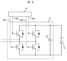
具体的には、以下のような構成となる。即ち、風力発電機3の固定子の電力出力側には、蓄電装置9を備えた複数の電力変換装置8が風力発電機3と直列に接続され、電力系統500に連系されている。この複数の電力変換装置8は、図2に示すように、代表的には直流電圧安定化のためのコンデンサ81を有するPWMインバータで構成されている。また、これらの電力変換装置8は蓄電装置9を備えており、PWMインバータのスイッチ動作によって個々の蓄電装置9を電圧源とした電圧が電力変換装置8から出力されることから、電力変換装置8全体で可変電圧源として作用することになる。
図1に示すように、複数の直列接続の電力変換装置8は、電力変換装置制御器10によりその動作が制御される。この電力変換装置制御器10の入力信号は、風力発電機3の電圧S3、有効電力及び無効電力の各設定値S7、電力系統500の系統電圧S9及び系統電流S8である。また、電力変換装置8の出力信号は、電力変換装置8を構成しているPWMインバータのON及びOFFのスイッチ動作要求信号S6である。ここで、有効電力の設定値S7は、風力発電機3から得られる発電電力を考慮する必要があり、風力発電機3と電力変換装置8から出力される有効電力の合計値として設定される。また、電力変換装置8が有効電力制御を行うことから無効電力は「0」設定される。
この電力変換装置制御器10の制御目的は、風力発電機3の固定子電圧に対し、蓄電装置9を電圧源とする電力変換装置8の出力電圧を加算して電圧振幅を調整し、系統電圧と一致させることにある。ここで、風力発電機3の固定子電圧は交流であり、また、電力系統500の電圧も交流である。一方、それぞれの蓄電装置9は一定電圧を出力する。このため、風力発電機3に直列に接続された複数の電力変換装置8のPWMインバータのON及びOFFのスイッチ動作で複数の一定電圧波形を発生し、最終的には、これらの複数の電力変換装置8の出力電圧波形の加算により、電力系統500の電圧と同じ周波数の交流電圧波形を生成する。
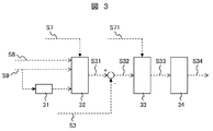
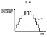
電力変換装置制御器10の制御動作について、図3を用いて説明する。電力変換装置8のPWMインバータのON及びOFFのスイッチ動作は、図4に示す電圧波形のように、目標とする電圧波形Aである変調波電圧とPWMインバータのON及びOFFさせるための閾値電圧であるキャリア信号とを比較し決定する。直列接続された複数個の電力変換装置8がある場合には、変調波電圧信号を電力変換装置8の数だけ多段階レベルに分割し(図5参照)、それぞれの電力変換装置8が受け持つ電圧レベルにおいて電圧レベルをシフトした複数のキャリア信号で比較することにより、それぞれ対応する電力変換装置8のPWMインバータのON及びOFF動作を制御する。即ち、図5に示すように、目標とする変調波電圧信号に対して複数の電圧レベルV1~V5でPWM変調するものである。最終的には、目標とする変調波電圧信号に対して複数の電力変換装置8のPWMインバータがON及びOFF動作することにより、複数の電圧レベルでPWM変調された電圧が得られる。つまり、電力変換装置8が複数直列に接続されているため、図6に示すように、電力変換装置8からの合計電圧Vが変調波電圧信号に対応して出力される。
この時、電力変換装置8が目標とする変調波電圧信号は、以下のように演算される。即ち、変調波電圧信号は、電力変換装置8から出力される有効電力及び無効電力に依存し、また、電力系統500の電流信号にも依存する。つまり、図3に示すように、上記有効電力及び無効電力の設定値S7、電力系統500の系統電流S8及び系統電圧S9に基づき、変調波電圧生成部32で有効電力制御演算を行って電力変換装置8から有効電力を出力するための電圧信号、即ち、変調波電圧信号S31を計算する。この時、電力系統500の系統電圧信号S9に基づき、系統電圧の位相及び周波数を位相検出部31で求め、有効電力制御のための変調波電圧信号演算に利用する。
変調波電圧生成部32で演算された電力変換装置8からの目標変調波電圧信号S31に対し、風力発電機3の出力である固定子電圧信号S3を加算し、修正変調波電圧信号S32を得る。この修正変調波電圧信号S32は蓄電装置9の電圧の加算信号S71により規格化され、PWMインバータ33へ出力される。従って、この規格化された変調波電圧信号S33に対し、前述したように、電圧レベルをシフトした複数のキャリア信号で電圧比較部34にて比較され、それぞれに対応する電力変換装置8のPWMインバータのON及びOFF動作の制御信号S34を生成する。
以上、蓄電装置9を備えた複数の電力変換装置8を介して風力発電機3と電力系統500とを連系する風力発電システムについて、その発電システムの構成を説明した。
これまでの説明で明らかなように、風速の増加により風力発電機3の発電電圧と電力系統500の系統電圧との電圧差がない場合においては、蓄電装置9を備えた電力変換装置8による電圧調整の必要性はない。このような場合においては、図3に示したPWMインバータ33をバイパス動作させ、蓄電装置9の電圧が電力変換装置8から出力されないようにする。この時、本発明の風力発電システムの発電特性は、従来の二次励磁型発電機を使用した風力発電機による風力発電システムとほぼ同等となる。
二次励磁型発電機を使用した風力発電機3に対し、蓄電装置9を備えた複数の電力変換装置8を直列に接続し、更に、これらの電力変換装置8を介して電力系統500に連系した時の電圧波形について、図7乃至図9にその一例を示す。
図7乃至図9において、それぞれの電圧波形の周波数は同一であり、図示してないが、電圧と電流との位相差によって、風力発電機3及び電力変換装置8と電力系統500との間で有効電力の流れが発生する。
先ず、図7に示した風力発電機3の固定子電圧であるが、これは風力発電機3の回転子励磁系の動作により、風力発電機3の回転子回転数によらず電力系統500の同期回転数(周波数)で風力発電機3の電力として出力される。この時、風力発電機3の固定子電圧は、回転子励磁系の直流リンク部の直流電圧制御によって、電力系統500の系統電圧より低く維持されている。この風力発電機3の電圧が低く維持されている状態は、風速が減少して風力発電機3の電圧が低下し系統電圧を維持できないような場合に相当する。
次に、蓄電装置9を備えた複数の電力変換装置8から出力される合計電圧を図8に示す。前述したように、電力変換装置8から出力される電圧波形は、変調波電圧波形に対して蓄電装置9を直流電源とし複数レベルでPWM変調し出力されたものである。従って、実際には、それぞれ異なった電圧レベルで電力変換装置8から出力されるために、その合計電圧は階段状の電圧波形となる。ここでは、その階段状の電圧波形をフィルター等による成形後の波形として示している。また、この時の電力系統500の系統電圧を図9に示す。
風力発電機3と蓄電装置9を備えた電力変換装置8とは、前述したように直列接続されているため、風力発電機3の固定子の電圧と電力変換装置8から出力される電圧とは加算されることになる。電力変換装置8に対する変調波電圧信号は、この加算された電圧信号が電力系統500の電圧信号と電圧差がないように生成される。
その結果、風力発電機3は、蓄電装置9を備えた電力変換装置8を介して安定に電力系統に連系され、風力発電システムの低風速における運転可能範囲を拡張でき、結果として発電設備の利用率を向上させることができる。
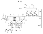
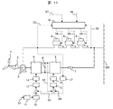
図10に、本発明の風力発電システムの実施例2を示す。なお、図1に示し実施例1と同一の符号を付された構成と同一の機能を有する部分については、その説明は省略する。
該図に示す本実施例は、風力発電機3と蓄電装置9を備えた複数の電力変換装置8とを直列に接続すると共に、系統側電力変換器5と最も風力発電機3側に位置する電力変換装置8との間に遮断器等の第1の開閉器100を、風力発電機3と最も風力発電機3側に位置する電力変換装置8との間に遮断器等の第2の開閉器101を、電力系統500と最も電力系統500側に位置する電力変換装置8との間に遮断器等の第3の開閉器102をそれぞれ設置し、そして、電力系統500と最も電力系統500側に位置する電力変換装置8との間に設置された第3の開閉器102を開放し、複数の電力変換装置8を電力系統500から切り離した風力発電システムの構成としたものである。
即ち、第3の開閉器102及び第2の開閉器101が開放された状態、また、第1の開閉器100が閉状態とする(この時、図示してないが、電力変換器8の電力系統500側は、三相交流結線の終端が短絡されている)。図10において、初期的には蓄電装置9を備えた電力変換装置8の制御により、風力発電機3の回転子励磁系の直流リンク部の直流コンデンサ6を充電し、回転子励磁系を動作可能とする。風速の増加によって、風力発電機3の固定子電圧が上昇すると第2の開閉器101を開放状態から閉状態とすると共に、電力変換装置8のPWMインバータを制御して蓄電装置9を充電するものである。
このような本実施例の風力発電システムの構成とすることにより、上述した実施例1と同様な効果が得られることは勿論、風力発電機3で発生した電力を電力変換装置8に接続された蓄電装置9に供給することで、蓄電装置9の充電が可能となる。
特に、本実施例では、風力発電機3が電力系統500に連系できない低風速の状態の場合においても、風力発電システム単独で発電動作させることができ、発生した電力を電力変換装置8に接続された蓄電装置9に充電することで、風力エネルギーを電気エネルギーとして蓄電することができるようになる。
なお、蓄電装置9に蓄電された電力は、風力発電システムが電力系統500と連系後に、風力発電システムに対する電力要求に応じて電力系統500に供給される。
図11に、本発明の風力発電システムの実施例3を示す。なお、図1に示し実施例1と同一の符号を付された構成と同一の機能を有する部分については、その説明は省略する。
該図に示す本実施例が、実施例1に示した風力発電システムと異なる点は以下となる。
即ち、蓄電装置9を備えた複数の電力変換装置8の一方の端子は、風力発電機3の固定子に接続されると共に、電力変換装置8の他方の端子は、風力発電機3の回転子励磁系の系統側電力変換器5に接続され、更に、電力変換装置8の一方の端子は、電力系統500側に接続された風力発電システムの構成としたものである。言い換えると、風力発電機3の回転子励磁系の一端が風力発電機3の回転子と接続され、更に、風力発電機3の回転子励磁系の他端である系統側電力変換器5が電力系統500と最も電力系統500側に位置する電力変換装置8との間に接続されていることでもある。
このような本実施例の風力発電システムの構成とすることにより、風力発電機3の固定子の発電電圧が電力系統500の系統電圧と異なった場合において、蓄電装置9を備えた電力変換装置8の出力電圧の加算により電圧調整されることから、風力発電機3は電力系統500と安定に連系することができる。
なお、この時、風力発電機3の固定子励磁系の直流リンク部の直流電圧は、系統側電力変換器5により電力系統500の系統電圧に対応した直流電圧値に制御される。
図12に、本発明の風力発電システムの実施例4を示す。なお、図1に示し実施例1と同一の符号を付された構成と同一の機能を有する部分については、その説明は省略する。
該図に示す本実施例が、実施例1で示した風力発電システムと異なる点は以下となる。
即ち、本実施例は、風力発電機としてかご型誘導発電機3Aを使用した風力発電システムの実施例であり、このかご型誘導発電機3Aの固定子に蓄電装置9を備えた複数の電力変換装置8が直列に接続され、更に、これらの電力変換装置8は電力系統500に接続されていると共に、かご型誘導発電機3Aと最もかご型誘導発電機3A側に位置する電力変換装置8の間に遮断器等の開閉器103、電力系統500と最も電力系統500側に位置する電力変換装置8の間に遮断器等の開閉器104を設置した風力発電システムの構成としたものである。なお、開閉器103及び104は、かご型誘導発電機3Aと電力系統500の周波数が同じになった時に投入するものである。
風力発電機としてかご型誘導発電機3Aを使用した本実施例の風力発電システムの基本的な発電特性は、以下のようなものである。
即ち、かご型誘導発電機3Aは発電機構造体が回転子励磁系を構成しており、かご型誘導発電機3Aの固定子電流による誘導磁界によって発生した回転子電流に基づいて、発電のために必要な磁界を維持する。この時、かご型誘導発電機3Aの回転子は、電力系統500の系統周波数とわずかにずれた滑り回転数で回転する。風速の変化によってかご型誘導発電機3Aの発生電圧が変化するような場合には、かご型誘導発電機3Aの固定子が電力系統500と接続されていることから、かご型誘導発電機3Aの固定子電圧と電力系統500の系統電圧の電圧差をなくすようにかご型誘導発電機3Aの電流が変化し、その結果、かご型誘導発電機3Aの電圧及び電流の周波数は殆ど変ることなく、かご型誘導発電機3Aから得られる電力が変化する。
このように、かご型誘導発電機3Aを使用した風力発電機の入力エネルギーである風速が変化した場合、風速に応じて発生する発電電力が変化する発電特性を示す。風速が急激に変化した場合には、一時的にかご型誘導発電機3Aの電圧が大きく変化し、その結果、電力系統500へ供給される電力も変化して電力系統500の擾乱となる。
蓄電装置9を有する電力変換装置8を、このかご型誘導発電機3Aと電力系統500との間に組み入れた場合、電力変換装置8が出力する電圧をかご型誘導発電機3Aの電圧S3に加減算することにより、急激な風速変化で変化したかご型誘導発電機3Aの電圧変化に対して蓄電装置9の充放電により電圧調整することができる。
これにより、電力系統500の系統電圧との電圧差を短時間でなくすことができ、その結果、電力系統500に対する電力擾乱を抑制することが可能となる。
即ち、電力変換装置制御器10では、電力系統500の系統電圧S9及び系統電流S8、電力変換装置8から出力する電力設定値S7に基づいて、複数直列接続された電力変換装置8の全体動作を制御するための目標変調波電圧を求める。この目標変調波電圧に対して、かご型誘導発電機3Aの発生電圧を加減演算して修正目標変調波電圧を演算する。その後、前述した複数の直列接続された電力変換装置8のそれぞれ対し、修正目標変調波電圧を動作制御信号として分配し、電力変換装置8に接続された蓄電装置9の充放電の制御によって所定の電力変換装置8の出力電圧を得る。
一例として、風力発電システムがある風速で安定に風力発電している状態では、かご型誘導発電機3Aの発電電圧は電力系統500の系統電圧との電圧差はなく、電力変換装置8の出力電力設定値が「0」の条件では、蓄電装置9を備えた電力変換装置8はバイパスされた状態となっている。風速の変化によってかご型誘導発電機3Aの電圧が変化した場合には、電力変換装置8の出力電力の設定値を変えることにより、電力変換装置8の動作を制御して電力変換装置8に接続された蓄電装置9を充放電させて電力変換装置8の出力電圧を調整し、電力変換装置8の電力系統500側の電圧と電力系統500の系統電圧との電圧差をなくす。これにより、風速変化時のかご型誘導発電機3Aの電圧変化に伴って電力系統500へ供給される電力変動を抑制できる。
以上、本発明では、風力発電システムについて二次励磁型発電機、永久磁石発電機、かご型誘導発電機を風力発電機3として利用した場合を実施例として説明したが、これまでの実施例の説明で明らかなように、発電機の発生電力が入力エネルギーで変化するような可変速揚水発電システム、潮力発電システムなどの発電システムへの適用が可能である。
また、発電機の三相交流の各相に対し、電力変換装置として複数の単相インバータを直列接続するものであり、三相交流に限るものではないことは明らかである。
なお、本発明は上記した実施例に限定されるものではなく、様々な変形例が含まれる。例えば、上記した実施例は本発明を分かり易く説明するために詳細に説明したものであり、必ずしも説明した全ての構成を備えるものに限定されるものではない。また、ある実施例の構成の一部を他の実施例の構成を置き換えることが可能であり、また、ある実施例の構成に他の実施例の構成を加えることも可能である。また、各実施例の構成の一部について、他の構成の追加・削除・置換をすることが可能である。
1…風車、2…増速ギア、3…風力発電機、3A…かご型誘導発電機、4…回転子側電力変換器、5…系統側電力変換器、6…直流コンデンサ、7…リアクタンス、8…電力変換装置、9…蓄電装置、10…電力変換装置制御器、11…演算器、12…速度制御系、13…電力制御系、14…電流制御系、15…直流電圧制御器、16…電流制御器、17…電力計算部、31…位相検出部、32…変調波電圧生成部、33…PWMインバータ、34…電圧比較部、81…コンデンサ、100…第1の開閉器、101…第2の開閉器、102…第3の開閉器、103、104…開閉器、500…電力系統。
Claims (12)
- 発電機と、該発電機に一端が接続されていると共に、他端が電力系統に接続され、かつ、蓄電装置を有する複数の電力変換装置とを備え、
前記発電機と前記複数の電力変換装置が直列に接続され、前記発電機と前記電力系統に電圧差が生じた際に、前記電力変換装置を制御することによって、前記蓄電装置を充放電させて前記電圧差をなくすように前記電力変換装置の前記電力系統側の出力電圧が加減調整されることを特徴とする発電システム。 - 請求項1に記載の発電システムにおいて、
前記複数の電力変換装置が制御される電力変換装置制御器を備え、該電力変換装置制御器は、前記発電機の固定子電圧に対し、前記蓄電装置を電圧源とする前記電力変換装置の出力電圧を加算して電圧振幅を調整し、前記電力系統の電圧と一致させる制御を行うことを特徴とする発電システム。 - 風を受けて回転する風車により駆動される風力発電機と、該風力発電機に一端が接続されていると共に、他端が電力系統に接続され、かつ、蓄電装置を有する複数の電力変換装置とを備え、
前記風力発電機の固定子と前記複数の電力変換装置が直列に接続され、前記風力発電機と前記電力系統に電圧差が生じた際に、前記電力変換装置を制御することによって、前記蓄電装置を充放電させて前記電圧差をなくすように前記電力変換装置の前記電力系統側の出力電圧が加減調整されることを特徴とする風力発電システム。 - 請求項3に記載の風力発電システムにおいて、
前記複数の電力変換装置が制御される電力変換装置制御器を備え、該電力変換装置制御器は、前記風力発電機の固定子電圧に対し、前記蓄電装置を電圧源とする前記電力変換装置の出力電圧を加算して電圧振幅を調整し、前記電力系統の電圧と一致させる制御を行うことを特徴とする風力発電システム。 - 請求項3又は4に記載の風力発電システムにおいて、
前記風力発電機の回転子と前記電力変換装置の間には、前記風力発電機からの交流電力を直流電力に変換する系統側電力変換器と直流電力を交流電力に変換する回転子側電力変換器から成る回転子励磁系が接続されていることを特徴とする風力発電システム。 - 請求項5に記載の風力発電システムにおいて、
前記系統側電力変換器と最も前記風力発電機側に位置する前記電力変換装置との間に第1の開閉器が、前記風力発電機と最も該風力発電機側に位置する前記電力変換装置との間に第2の開閉器が、前記電力系統と最も該電力系統側に位置する前記電力変換装置との間に第3の開閉器がそれぞれ設置され、かつ、前記第3の開閉器が開放され、前記電力変換装置が電力系統から切り離された状態で、前記風力発電機からの電力を前記蓄電装置に供給して充電することを特徴とする風力発電システム。 - 風を受けて回転する風車により駆動される風力発電機と、該風力発電機に一端が接続されていると共に、他端が電力系統に接続され、かつ、蓄電装置を有する複数の電力変換装置と、前記風力発電機からの交流電力を直流電力に変換する系統側電力変換器と直流電力を交流電力に変換する回転子側電力変換器から成る回転子励磁系とを備え、
前記風力発電機の固定子と前記複数の電力変換装置が直列に接続されていると共に、前記回転子励磁系の一端が前記風力発電機の回転子と接続され、該回転子励磁系の他端である前記系統側電力変換器が前記電力系統と最も該電力系統側に位置する前記電力変換装置との間に接続され、かつ、前記風力発電機と前記電力系統に電圧差が生じた際に、前記電力変換装置を制御することによって、前記蓄電装置を充放電させて前記電圧差をなくすように前記電力変換装置の前記電力系統側の出力電圧が加減調整されることを特徴とする風力発電システム。 - 請求項7に記載の風力発電システムにおいて、
前記複数の電力変換装置が制御される電力変換装置制御器を備え、該電力変換装置制御器は、前記風力発電機の固定子電圧に対し、前記蓄電装置を電圧源とする前記電力変換装置の出力電圧を加算して電圧振幅を調整し、前記電力系統の電圧と一致させる制御を行うことを特徴とする風力発電システム。 - 請求項3乃至8のいずれか1項に記載の風力発電システムにおいて、
前記電力変換装置は、直流電力を交流電力に変換する機能或いは交流電力を直流電力に変換する機能を有する単相インバータであり、該単相インバータは、前記風力発電機で発生した多相交流のそれぞれの相に対して複数個直列に接続されると共に、前記風力発電機と前記電力系統との間に配置接続されることを特徴とする発電システム。 - 請求項3乃至8のいずれか1項に記載の風力発電システムにおいて、
前記電力変換装置は、複数個直列接続された単相インバータであり、前記電力系統の系統電圧及び系統電流と前記単相インバータからの出力電力の設定値とに基づいて、複数個直列接続された前記単相インバータの全体動作を制御するための目標変調波電圧を求め、更に、前記風力発電機の発生電圧を加減演算して修正目標変調波電圧を演算した後、前記複数個の前記単相インバータのそれぞれの動作制御信号として分配し、前記単相インバータに接続された前記蓄電装置の充放電の制御により所定の単相インバータ電圧を得ることを特徴とする風力発電システム。 - 風を受けて回転する風車により駆動されるかご型誘導発電機と、該かご型誘導発電機に一端が接続されていると共に、他端が電力系統に接続され、かつ、蓄電装置を有する複数の電力変換装置とを備え、
前記かご型誘導発電機の固定子と前記複数の電力変換装置が直列に接続され、前記かご型誘導発電機と前記電力系統に電圧差が生じた際に、前記電力変換装置を制御することによって、前記蓄電装置を充放電させて前記電圧差をなくすように前記電力変換装置の前記電力系統側の出力電圧が加減調整されることを特徴とする風力発電システム。 - 請求項11に記載の風力発電システムにおいて、
前記複数の電力変換装置が制御される電力変換装置制御器を備え、該電力変換装置制御器は、前記電力系統の系統電圧及び系統電流と前記電力変換装置から出力する電力設定値に基づいて前記複数の電力変換装置の全体動作を制御するための目標変調波電圧を求め、この目標変調波電圧に対して前記かご型誘導発電機の発生電圧を加減演算して修正目標変調波電圧を演算し、その後、前記複数の電力変換装置のそれぞれ対し、前記修正目標変調波電圧を動作制御信号として分配し、前記蓄電装置の充放電によって前記電力変換装置の所定の出力電圧を得る制御を行うことを特徴とする風力発電システム。
Priority Applications (1)
| Application Number | Priority Date | Filing Date | Title |
|---|---|---|---|
| PCT/JP2012/078687 WO2014073030A1 (ja) | 2012-11-06 | 2012-11-06 | 発電システム及び風力発電システム |
Applications Claiming Priority (1)
| Application Number | Priority Date | Filing Date | Title |
|---|---|---|---|
| PCT/JP2012/078687 WO2014073030A1 (ja) | 2012-11-06 | 2012-11-06 | 発電システム及び風力発電システム |
Publications (1)
| Publication Number | Publication Date |
|---|---|
| WO2014073030A1 true WO2014073030A1 (ja) | 2014-05-15 |
Family
ID=50684170
Family Applications (1)
| Application Number | Title | Priority Date | Filing Date |
|---|---|---|---|
| PCT/JP2012/078687 Ceased WO2014073030A1 (ja) | 2012-11-06 | 2012-11-06 | 発電システム及び風力発電システム |
Country Status (1)
| Country | Link |
|---|---|
| WO (1) | WO2014073030A1 (ja) |
Cited By (2)
| Publication number | Priority date | Publication date | Assignee | Title |
|---|---|---|---|---|
| JP2018207628A (ja) * | 2017-06-01 | 2018-12-27 | 三菱電機エンジニアリング株式会社 | 風力発電機 |
| JP2022532276A (ja) * | 2019-11-22 | 2022-07-14 | アーベーベー・シュバイツ・アーゲー | 電気装置、電力供給システム及び電気装置の製造方法 |
Citations (4)
| Publication number | Priority date | Publication date | Assignee | Title |
|---|---|---|---|---|
| JP2005080414A (ja) * | 2003-09-01 | 2005-03-24 | Mitsubishi Electric Corp | 電力変換装置及びそれを用いたパワーコンディショナ |
| JP2010071159A (ja) * | 2008-09-17 | 2010-04-02 | Univ Of Ryukyus | 風車と蓄電池による風力発電電力平滑化装置 |
| JP2010104233A (ja) * | 2010-01-29 | 2010-05-06 | Mitsubishi Electric Corp | 電力変換装置 |
| WO2012140757A1 (ja) * | 2011-04-14 | 2012-10-18 | 三菱重工業株式会社 | 風力発電設備の出力平準化方法及び風力発電設備の出力平準化装置 |
-
2012
- 2012-11-06 WO PCT/JP2012/078687 patent/WO2014073030A1/ja not_active Ceased
Patent Citations (4)
| Publication number | Priority date | Publication date | Assignee | Title |
|---|---|---|---|---|
| JP2005080414A (ja) * | 2003-09-01 | 2005-03-24 | Mitsubishi Electric Corp | 電力変換装置及びそれを用いたパワーコンディショナ |
| JP2010071159A (ja) * | 2008-09-17 | 2010-04-02 | Univ Of Ryukyus | 風車と蓄電池による風力発電電力平滑化装置 |
| JP2010104233A (ja) * | 2010-01-29 | 2010-05-06 | Mitsubishi Electric Corp | 電力変換装置 |
| WO2012140757A1 (ja) * | 2011-04-14 | 2012-10-18 | 三菱重工業株式会社 | 風力発電設備の出力平準化方法及び風力発電設備の出力平準化装置 |
Cited By (4)
| Publication number | Priority date | Publication date | Assignee | Title |
|---|---|---|---|---|
| JP2018207628A (ja) * | 2017-06-01 | 2018-12-27 | 三菱電機エンジニアリング株式会社 | 風力発電機 |
| JP2022532276A (ja) * | 2019-11-22 | 2022-07-14 | アーベーベー・シュバイツ・アーゲー | 電気装置、電力供給システム及び電気装置の製造方法 |
| JP7179995B2 (ja) | 2019-11-22 | 2022-11-29 | アーベーベー・シュバイツ・アーゲー | 電気装置、電力供給システム及び電気装置の製造方法 |
| US11670958B2 (en) | 2019-11-22 | 2023-06-06 | Abb Schweiz Ag | Electrical apparatus, power supply system and method of manufacturing the electrical apparatus |
Similar Documents
| Publication | Publication Date | Title |
|---|---|---|
| Pena et al. | Control system for unbalanced operation of stand-alone doubly fed induction generators | |
| Singh et al. | Solid state voltage and frequency controller for a stand alone wind power generating system | |
| US11680558B2 (en) | Grid-forming control of inverter-based resource using virtual impedance | |
| Samuel et al. | Grid interface of wind power with large split-winding alternator using cascaded multilevel inverter | |
| US20230041049A1 (en) | System and method for providing grid-forming control for a double-fed wind turbine generator | |
| JP2011160652A (ja) | 電流制御装置、ならびに電力変換制御のためのベクトル制御方法 | |
| EP3993246A1 (en) | System and method for neutral point balancing for back-to-back voltage source converters | |
| US20150249413A1 (en) | System and method for adjusting current regulator gains applied within a power generation system | |
| EP4012918B1 (en) | Method for operating an asynchronous inverter-based resource as a virtual synchronous machine to provide grid-forming control thereof | |
| JP2010161901A (ja) | インバータ制御回路、このインバータ制御回路を備えた系統連系インバータシステム | |
| Chatterjee et al. | An improved current balancing technique of two-winding IG suitable for wind-PV-based grid-isolated hybrid generation system | |
| US11486355B2 (en) | Method for operating doubly-fed wind turbine generator as a virtual synchronous machine to provide grid-forming control thereof | |
| US12126298B2 (en) | Methods of operating doubly-fed induction generator systems | |
| US12009770B2 (en) | System and method for providing grid-forming control of an inverter-based resource | |
| Rudraraju et al. | A control strategy for reliable power output from a stand-alone WRIG with battery-supported DC link | |
| Ren et al. | Grid fault ride through of a medium-voltage three-level full power wind power converter | |
| WO2014073030A1 (ja) | 発電システム及び風力発電システム | |
| Babazadeh et al. | Controller design for a hybrid energy storage system enabling longer battery life in wind turbine generators | |
| US20220271695A1 (en) | System and method for providing grid-forming control for a double-fed wind turbine generator | |
| Bubalo et al. | Optimized isolated operation of a WECS-powered microgrid with a battery-assisted qZSI | |
| EP4123861A2 (en) | Voltage control loop for mitigating flicker in a grid-forming inverter-based resource | |
| Deshpande et al. | Output power maximization of wind energy conversion system using doubly fed induction generator | |
| JP6453107B2 (ja) | 発電システム | |
| CN112368902A (zh) | 具有直流电压源和控制单元的逆变器 | |
| Pathak et al. | Permanent magnet synchronous generator based wind energy and DG hybrid system |
Legal Events
| Date | Code | Title | Description |
|---|---|---|---|
| 121 | Ep: the epo has been informed by wipo that ep was designated in this application |
Ref document number: 12888022 Country of ref document: EP Kind code of ref document: A1 |
|
| NENP | Non-entry into the national phase |
Ref country code: DE |
|
| 122 | Ep: pct application non-entry in european phase |
Ref document number: 12888022 Country of ref document: EP Kind code of ref document: A1 |
|
| NENP | Non-entry into the national phase |
Ref country code: JP |